TCU20A30-11A中文资料
TC301A(B)_中文手册_V2.0
TC301A(B)中文手册目录1.概述 (1)2.特点 (1)3.应用 (2)4.管脚图示 (2)5.管脚描述 (2)6.应用原理图 (3)7.PCB版图注意事项 (3)8.额定值 (4)9.电气特性 (4)10.ESD特性 (4)11.封装尺寸图(SOT23-6L) (5)1.概述人机接口要求更高的功能性和直观性,触摸式界面,迅速成为新的规范。
TC301A(B)是一个单按键电容传感装置。
该装置可以作为一个单键控制器。
2.特点☐可以控制1个按键☐自动灵敏度校正☐系统低成本☐降低系统复杂度提高稳定性☐嵌入的共模干扰去除电路☐RoHS兼容的SOT23-6L封装3.应用☐媒体播放器☐消费类电子☐家电应用☐键盘☐传统按键替换☐密封控制面板4.管脚图示5.管脚描述引脚名称输入/输出描述1VREG模拟输出内部参考源输出2VSS电源负极地参考3VCC电源正极供电电压输入4OUT输出按键输出5CX模拟输入输出感应天线6SEN模拟输入输出灵敏度电容SEN此管脚电容大小为15pf~100pf,电容越小灵敏度越高。
VREG内部参考源输出,接4.7nf电容。
CX感应天线,串联电阻是3KΩ。
OUT按键输出端口,有高阻和低电平两种状态。
6.应用原理图7.PCB版图注意事项1.VCC和VSS电源线要单独走线,不能和其它芯片(单片机和LCD驱动芯片等)共用电源走线。
以免使其它芯片的干扰信号通过电源线引到触摸芯片。
2.CP,CVREG,CSEN三个电容必须靠近芯片放置。
感应线上串联的CX电阻,靠近芯片放置为宜。
3.尽量大的铺地面积,可以提高抗干扰性。
4.感应连线和感应焊盘优先布局。
芯片靠近感应焊盘放置,感应连线直接引到感应焊盘(或弹簧焊盘),不同按键的感应连线不需要长度一致。
感应连线线宽尽量小。
感应连线周围不能走其他电源线和信号线。
如果实在不能避免,其他走线要垂直跨过感应连线。
感应焊盘之间至少留5mm间距,感应焊盘和铺地之间距离大于1.5mm。
Ith20A是表示接触器的一个重要的技术参数
Ith20A是表示接触器的一个重要的技术参数,叫做热稳定电流值,也就是可以在两秒钟内可以通过的最大电流值。
20A不是触点的额定工作电流,而是瞬间通过的最大的电流。
交流接触器主要技术参数有:1)接触器额定绝缘电压(Ui)2)额定工作电压(Ue)、3)额定发热电流(Ith)、4)额定工作电流(Ie)5)额定工作功率额定发热电流(Ith):有的地方就叫发热电流(Ith),其实是应该叫做热稳定电流(额定短时耐受电流)Ith。
关于热稳定电流(额定短时耐受电流)Ith在高压断路器中有人这样解释的:当短路电流通过高压断路器时,不仅会产生很大的电动力,而且还会产生很多的热量。
短路电流所产生的热量与电流的平方成正比,而热量的散发与时间成反比。
由于短路时电流很大,该电流在短时间内将产生大量的热量不能及时散发,因而高压断路器的温度将显著上升,严重时会使高压断路器的触头焊住,损坏高压断路器,甚至引起高压断路器爆炸。
因此,高压断路器铭牌上规定了一定时间(规定标准时间为2s,需要大于2s时可用4s)的热稳定电流。
在4s内,能够保证高压断路器不损坏的条件下允许通过的短路电流值,称为4s热稳定电流。
在铭牌上热稳定电流以额定短时耐受电流(短路电流有效值)表示。
Ith20A的意思就是它在很短时间可以承受20安的电流,估计额定工作电流就只有十几安左右了。
如一个继电器的主要技术参数:a、额定绝缘电压 Ui : 600Vb、额定工作电压 Ue : AC 277V 。
c、额定工作电流: Ie=30A (AC-8b); Ith=40A 。
d、机械寿命> 100 万次;电寿命> 10万次。
e、线圈工作电压范围:继电器线圈在70% Us~110% Us范围内可靠吸合并工作,释放电压在20% Us~ 70% Us范围内。
f、产品线圈工作电压 Us=208 ~240V 。
它的热稳定电流为40A,但额定工作电流就只有30A。
在交流接触器上面显示的 Ith Ics Icu 是什么意思? Uimp 是什么意思?断路器上面 Ir Im 曲线是什么意思?Ith 约定发热电流Ics 使用分断能力一种性能越大越好Icu 极限分断能力Uimp 额定冲击耐压就是最大瞬间承受的电压Ir 脱扣电流值(一倍额定电流以下的调节)具体看实物上都是多少Im 脱扣电流值(一倍额定电流以上的调节)ue额定电压:le额定电流:pe额定功率:对应的220,380,660是不同的电压等级线圈电压看不出来,一般会再线圈的接线的位置有标明的,380v的电机可以使用5.5KW的交流接触器的选用,应根据负荷的类型和工作参数合理选用。
美国电子设备制造商Eaton的电磁开关器件说明书
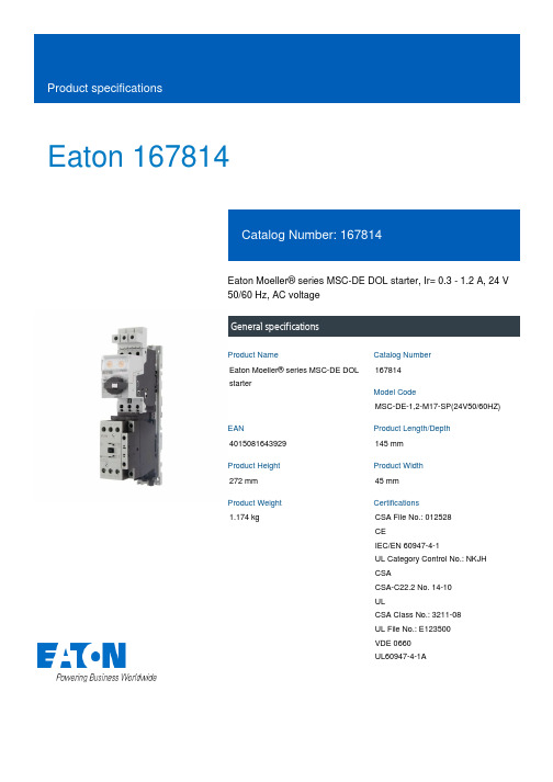
Eaton 167814Eaton Moeller® series MSC-DE DOL starter, Ir= 0.3 - 1.2 A, 24 V 50/60 Hz, AC voltageGeneral specificationsEaton Moeller® series MSC-DE DOL starter167814MSC-DE-1,2-M17-SP(24V50/60HZ)4015081643929145 mm 272 mm 45 mm 1.174 kgCSA File No.: 012528 CEIEC/EN 60947-4-1UL Category Control No.: NKJH CSACSA-C22.2 No. 14-10 ULCSA Class No.: 3211-08 UL File No.: E123500 VDE 0660 UL60947-4-1AProduct NameCatalog Number Model CodeEANProduct Length/Depth Product Height Product Width Product Weight Certifications1.2 AIs the panel builder's responsibility. The specifications for the switchgear must be observed.7.5 kW208 - 480 V AC14 kA, 240 V, SCCR (UL/CSA)14 kA, 480 Y/277 V, SCCR (UL/CSA)0 A24 VMeets the product standard's requirements.Is the panel builder's responsibility. The specifications for the switchgear must be observed.DIN rail≤ 500 ms, main conducting paths, AC-4 cycle operationDoes not apply, since the entire switchgear needs to be evaluated.0.37 kW0.37 kWMeets the product standard's requirements.Motor Starters in System xStart - brochureSimple, flexible and safe! Distribution system for motor-starter combinationsSave time and space thanks to the new link module PKZM0-XDM32ME Product Range Catalog Switching and protecting motorsDA-DC-00004245.pdfDA-DC-00004109.pdfeaton-manual-motor-starters-msc-d-dol-starter-dimensions.epseaton-manual-motor-starters-msc-d-dol-starter-3d-drawing.epseaton-manual-motor-starters-mounting-msc-d-dol-starter-3d-drawing.eps DA-CE-ETN.MSC-DE-1,2-M17-SP(24V50_60HZ)IL03402052ZWIN-WIN with push-in technologyDA-CS-msc_de_spDA-CD-msc_de_speaton-manual-motor-starters-device-msc-d-dol-starter-wiring-diagram.epsRated operational current for specified heat dissipation (In) 10.11 Short-circuit ratingRated operational power at AC-3, 380/400 V, 50 Hz Rated operational voltageShort-circuit current rating (type E)Rated conditional short-circuit current, type 1, 480 Y/277 V Rated control supply voltage (Us) at AC, 50 Hz - min10.4 Clearances and creepage distances10.12 Electromagnetic compatibilityMounting methodCut-out periods - min10.2.5 LiftingRated power at 575 V, 60 Hz, 3-phaseRated power at 460 V, 60 Hz, 3-phase10.2.3.1 Verification of thermal stability of enclosures Rated control supply voltage (Us) at DC - min BrochuresCatalogs Certification reports DrawingseCAD model Installation instructions Installation videos mCAD modelWiring diagrams0 VFitted with:Short-circuit releaseCurrent flow times - min900 (Class 15) AC-4 cycle operation, Main conducting paths 1000 (Class 20) AC-4 cycle operation, Main conducting paths 500 (Class 5) AC-4 cycle operation, Main conducting paths 700 (Class 10) AC-4 cycle operation, Main conducting paths Note: Going below the minimum current flow time can cause overheating of the load (motor).For all combinations with an SWD activation, you need not adhere to the minimum current flow times and minimum cut-out periods.Number of pilot lightsShort-circuit current rating (high fault at 600 V)100 kA, Fuse, SCCR (UL/CSA)3 A, Class J/CC, max. Fuse, SCCR (UL/CSA)Rated control supply voltage (Us) at AC, 50 Hz - max24 V10.8 Connections for external conductorsIs the panel builder's responsibility.Coordination class (IEC 60947-4-3)Class 2Rated conditional short-circuit current, type 1, 600 Y/347 V0 APower consumption, sealing, 50 Hz2.1 CO, Coil in a cold state and 1.0 x UsAmbient operating temperature - max55 °CRated operational power at AC-3, 220/230 V, 50 Hz0.18 kWConnection to SmartWire-DTNoNumber of command positionsStatic heat dissipation, non-current-dependent Pvs2.1 WElectrical connection type of main circuitScrew connectionElectrical connection type for auxiliary- and control-current circuit Screw connectionRated control supply voltage (Us) at DC - max0 V10.9.3 Impulse withstand voltageIs the panel builder's responsibility.Ambient operating temperature - min-25 °C10.6 Incorporation of switching devices and componentsDoes not apply, since the entire switchgear needs to be evaluated.10.5 Protection against electric shockDoes not apply, since the entire switchgear needs to be evaluated.ClassAdjustable10.13 Mechanical functionThe device meets the requirements, provided the information in the instruction leaflet (IL) is observed.10.2.6 Mechanical impactDoes not apply, since the entire switchgear needs to be evaluated.10.9.4 Testing of enclosures made of insulating materialIs the panel builder's responsibility.10.3 Degree of protection of assembliesDoes not apply, since the entire switchgear needs to be evaluated.Heat dissipation per pole, current-dependent Pvid0.4 WActuating voltage24 V 50/60 HzVoltage typeACSwitching capacity (auxiliary contacts, general use)1 A, 250 V DC, (UL/CSA)15 A, 600 V AC, (UL/CSA)Overload release current setting - min0.3 AEquipment heat dissipation, current-dependent Pvid1.2 WHeat dissipation capacity Pdiss0 WRated operational current (Ie)16.7 AAssigned motor power at 460/480 V, 60 Hz, 3-phase0.5 HPNumber of auxiliary contacts (normally closed contacts)Rated conditional short-circuit current (Iq), type 2, 380 V, 400 V, 415 V0 A10.2.3.2 Verification of resistance of insulating materials to normal heatMeets the product standard's requirements.10.2.3.3 Resist. of insul. mat. to abnormal heat/fire by internal elect. effectsMeets the product standard's requirements.Overload release current setting - max1.2 A10.9.2 Power-frequency electric strengthIs the panel builder's responsibility.Overvoltage categoryIIIDegree of protectionIP20NEMA OtherPollution degree3Rated control supply voltage (Us) at AC, 60 Hz - min24 V10.7 Internal electrical circuits and connectionsIs the panel builder's responsibility.Rated impulse withstand voltage (Uimp)6000 V ACConnectionScrew terminals10.10 Temperature riseThe panel builder is responsible for the temperature rise calculation. Eaton will provide heat dissipation data for the devices.FunctionsTemperature compensated overload protectionRated conditional short-circuit current (Iq), type 2, 230 V0 ATypeStarter with electronic trip unit10.2.2 Corrosion resistanceMeets the product standard's requirements.10.2.4 Resistance to ultra-violet (UV) radiationMeets the product standard's requirements.10.2.7 InscriptionsMeets the product standard's requirements.Short-circuit release (Irm) - max186 ARated control supply voltage (Us) at AC, 60 Hz - max24 VRated operational current (Ie) at AC-3, 380 V, 400 V, 415 V 1.2 AModelDirect starterNumber of auxiliary contacts (normally open contacts)1AltitudeMax. 2000 mSwitching capacity (auxiliary contacts, pilot duty)P300, DC operated (UL/CSA)A600, AC operated (UL/CSA)Eaton Corporation plc Eaton House30 Pembroke Road Dublin 4, Ireland © 2023 Eaton. All Rights Reserved. Eaton is a registered trademark.All other trademarks areproperty of their respectiveowners./socialmedia。
艾顿产品集中电路断路器基于的传输开关说明书

EatonProduct Focus MCCB/MCSbreaker-based switchBuilt with years of experience Powered with innovation Delivered with reliabilityA History of Experience, Innovation and ReliabilityAs a premier industrial manufacturer, Eaton’s electrical business is one of the world’s leading suppliers of electrical control products and power distribution equipment. Eaton’s electrical products include a complete line of low and medium voltage assemblies from substations, switchgear and panelboards to loadcentres, transformers and safety switches. These products are used wherever there is a demand for electrical power in residences, high-rise apartment and office buildings, commercial sites, hospitals and factories.Built With ExperienceFor over a century, Eaton hasfocused on providing qualitypower-centric products andservices. In today’s businessenvironment, customers likeyou are driving ourtransformation from a leadingglobal electrical componentsprovider into a customer-centric solutions partner whounderstands your business.We do this through in-depthcollaboration with customersand subject matter expertsstudying the issues inherentto the electrical powerdistribution and controlsystems.Powered With InnovationEaton continues to meetchanging industry needs byproviding a broad range ofautomatic transfer switches.Eaton has used industry-leading breaker based designsfor years and these designscan be matched to a familyof automatic transfer switchcontrollers that will meet yourspecific needs. Identify yourapplication, define your needs,and select the solution fromEaton.Delivered With ReliabilityPower outages due to badweather or utility failure havegrown increasingly costly andmore disruptive to businessesand homeowners. A backuppower system will keep yourcomputers, security system,heating or refrigerationsystem, cash registers, homehealth care equipment, or anysystem that uses electricpower, energized andoperational. The demands forreliability have increased.Eaton meets thoseexpectations by the stringentCSA C22.2 No. 178 andUL1008 automatic transferswitches with a world-classproduct delivery system.Eaton will provide theindividual transfer switch builtto exacting standards orsupply the same transferswitch in an integratedlineup with other Eaton gear. 2EATONBreaker-based T ransfer Switches Sw itch Type -Automatic, Manualand Electrically Operated 30A-1000AProduct DescriptionAn economical line of transfer switches with micro-processor based logic, offering a standard feature package, for basic power applications on 30-1000 ampere systems up to 600 volts, 2, 3 or 4 pole.Electrical Ratings• Ratings 40, 100, 150, 200, 225, 260,400, 600, 800 and 1000 amperes• 2, 3 or 4-poles• Up to 600 Vac, 50/60 Hz.• NEMA® 1, 3R, Open, 12, 4, 4x• UL® 1008 listed• CSA C22.2 No. 178 certified Standard Features (ATC300+)• Switch position contacts:• Source 1 Position 1NO and 1NC• Source 2 Position 1NO and 1NC• Programmable Micro-processor based control• Normal/Standby source monitoring• Plant Exerciser with Failsafe (programmable)• High Withstand, Closing and Interrupting Ratings• Manual Transfer Under Load• Engine Start Contacts• Time Delay Normal to Emergency• Time Delay Engine Start• Time Delay Emergency to Normal• Time Delay Engine Cooldown• LED indicators – switch position• LED indicators – source available• Emergency source undervoltage/underfrequency sensing • Normal source undervoltage sensing• Time Delay Neutral• Go to Emergency Contact (Area Protection)• Pre-Transfer Signal Contacts• Pushbutton Bypass Time Delays• Load shed from emergency (Emergency Inhibit)Optional Features• Overcurrent protection with thermal-magnetic trip• Surge protection device• Remote annunciator controller—monitor andcontrol single or multiple automatic transfer switches• Ethernet gateway with Web server(Modbus TCP/IP, SNMP, BACnet)• Space heater with thermostat•Optional upgrade to ATC900Manual Transfer Switch Non-automatic Transfer switch Automatic Transfer switch3EATONAutomatic Breaker-based Transfer Switch Catalogue Numbering SystemTRANSFER SWITCH ENCLOSURE DIMENSIONS Frame size RatingFigure Height Width Depth F 30A - 150A, 600V 30A - 200A, 240V A 32.63” (829)24” (610)9” (229)K, L, M 225A - 600A B 55” (1397)32” (813)15” (381)N800A - 1200AB65” (1651)38” (965)16” (406)otes: N *225A single phase applications only **4 pole 600Vac 600A Use N Frame1 Manual configuration is available starting from K frame.2 Configurations with 4-pole NB MCCB (with trip unit) are not available4EATONBreaker-based T ransfer SwitchesSw itch Type -Bypass IsolationDouble Sided Bypass Isolation SwitchProduct DescriptionThe Eaton ® Bypass/Isolation Transfer Switch is designed for applications where preventative maintenance, inspection and testing must be accomplished while maintaining continuity of power to the load. Proven Eaton ® switch designsensure reliable transfer from normal to auxiliary power sources – for rapid restoration of essential power in critical applications.Electrical Ratings•Ratings 40, 100, 150, 200, 225, 260, 400, 600, 800 and 1000 amperes • 2, 3 or 4-poles• Up to 600 Vac, 50/60 Hz.• NEMA ® 1, 3R • UL ® 1008 listed•CSA ® C22.2 No. 178 certifiedSuperior Main Contact StructureThe Eaton ® Combination Bypass and AutomaticTransfer Switch is listed to CSA specifications C22.2 No. 178 and C22.2 No. 31.As an added plus the switching devices are listed under CSA C22.2 No. 5. Completely enclosed contacts provide both safety and reliability. They also ensure the integrity of the contact assemblies and minimize the need for periodic maintenance of the contacts, reducing the need for downtime and maintenance time.T ransfer Switch Is Easy T o Maintain And T estThe Eaton ® Bypass/Isolation Switch is designed torequire minimum maintenance even under the most strenuous of operating conditions. Due to the use of moulded caseswitches and their inherent self-protection capability, the contact structure and mechanism is extremely long lived.Our experience has shown that through normal operating conditions, the moving and stationary contacts will maintain their integrity for the full expected life of the transfer switch.When isolating and bypassing the transfer switch, a short term (less than 3 second) power interruption results. However, this is less than when transferring power after a power outage using a standard transfer switch. Also, with a double-sided bypass the transfer switch can be bypassed to either source quickly and easily regardless of the position or condition of the transfer switch.Safety T o Maintenance PersonnelIn most instances, the Bypass/Isolation Switch will be in theBypass Mode only during a maintenance or testing period. During this time, there could be operating personnel close to the equipment. The self protection capability of the Eaton ® switch would give these operators an extrameasure of safety during a rare coincidental fault condition.FeaturesThe Eaton ® Bypass Isolation Switch is available withall the options and features of our standard Transfer Switch product line. Proven, microprocessor based programmable controllers are supplied as standard on all Bypass TransferSwitches.5EATONBYPASS ISOLATION ATS (2 & 3 POLE) ENCLOSURE DIMENSIONSBREAKER-BASED TRANSFER SWITCH WITHSTAND/CLOSING RATINGSWhen protected by any manufacturers' breaker or Cutler-Hammer ®circuit breaker upstream as shown, the transfer switch is rated for use on a circuit capable of delivering not more than the RMS Symmetrical amps at the voltage shown below.25kA35kA 42kA 50kA 65kA 100kA 200kA 30 - 2002,3,4Any*Any*Any*Any*Any*Any*FDC,JDC,KDC 2252Any*Any*Any*Any*Any*Any*FDC,JDC,KDC3002,3,4Any*Any*Any*Any*Any*Any*KDC 4002,3,4Any*Any*Any*Any*Any*Any*KDC 6002,3,4Any*Any*Any*Any*Any*Any*LDC 800 - 10002,3,4Any*Any*Any*Any*Any*Any*---30 - 1502,3,4Any*Any*Any*Any*Any*(FDB/FD)+LFD 150kA FDC,JDC,KDC FCL***,LCL***200 - 3002,3,4Any*Any*Any*Any*Any*KDC,NB-TP**LCL***4002,3,4Any*Any*Any*Any*Any*------6002,3Any*Any*Any*Any*Any*NB-TP ---8002,3Any*Any*Any*Any*---NB-TP ---600 - 10004Any*Any*Any*Any*---------10002,3Any*Any*Any*Any*---------30 - 1502,3,4Any*Any*(FD/FDB)+LFD(FD/FDB)+LFD (FD/FDB)+LFD(FD/FDB)+LFD---KDCKDC KDCLCL200 - 3002,3,4Any*Any*Any*KDC KDC LCL ---4002,3,4Any*Any*Any*KDC KDC ------6002,3Any*Any*Any*LDC ---------6004Any*------------------800 - 10002,3,4Any*------------------*Any manufacturers’ breaker**with P12 limiter*** 150kA maximumTransfer Switch Ampere RatingVoltage120/240 and 240, 208Y/120480Y/277 and 480600Y/347 and 600Number of Poles SwitchedMaximum fault level available at upstream device (kA symmetrical)Upstream any manufacturers' breaker or Cutler-Hammer circuit breaker type BREAKER-BASED TRANSFER SWITCH WITHSTAND/CLOSING RATINGSWhen protected by an upstream fuse type shown, the transfer switch is rated for use on a circuit capable of delivering notmore than the RMS Symmetrical amps at the voltage shown below.30 - 2252,3,43002,3,44002,3,46002,3,4800 - 10002,3,430 - 1502,3,4200 - 3002,3,44002,3,46002,36004800 - 10002,3,4Transfer Switch Ampere Rating Voltage120/240 and 240, 208Y/120480Y/277,480,600Y/347 and 600Number of Poles SwitchedMax. Fuse AmperesMaximum fault level available at upstream device (kA symmetrical)Upstream Fuse Type 100kA 200kA ---J, T 200A J,T ---400A R J,T 400A J,T ---600A J,T R 600A L ---1200A L ---800A ---L 1600A ---L 1600A ---J,T 200A J,T ---400A R J,T 400A J,T ---600A J,T R 600A L ---1200A L ---800A ---L 1600A ---L 1600A ---L1600A7EATONT ransfer SwitchesAutomatic Transfer ControllersAutomatic Transfer Controllers Feature Selection Chart, continuedFeature Description ATC-300+ATC-900Voltage Specification System application voltage Up to 600 VacUp to 600 VacVoltage measurements Source 1 and 2—VAB, VBC and VCA Source 1, 2 and load—VAB, VBC and VCA Voltage measurement range 0–790 Vac rms 0–700 Vac rms Operating power65–145 Vac 65–160 Vac 24 Vdc (±10%)Frequency Specifications Frequency measurements Source 1 and 2Source 1 and 2Frequency measurement range 40–70 Hz40–70 HzEnvironmental Specifications Operating temperature range –20 to +70 °C –20 to +70 °C Storage temperature range –30 to +85 °C–30 to +85 °COperating humidity 0 to 95% relative humidity (noncondensing)0 to 95% relative humidity (noncondensing)Operating environment Resistant to ammonia, methane, nitrogen, hydrogen and hydro-carbonsResistant to ammonia, methane, nitrogen,hydrogen and hydrocarbonsFront Panel Indication Mimic diagram with LED indication Unit status, Source 1 and 2 available and connected (five total)Unit status, Source 1 and 2 available and connected (seven total)Main display LCD-based display, 2 lines, 16 characters LCD display, 4.3 inch color TFT (480x272)Display languageEnglish, French and Spanish English, French and Spanish Communications capable Modbus 485Modbus 485 or Ethernet TCP/IPEnclosure compatibility NEMA 1, 12, 3R and 4X UV resistant faceplate NEMA 1, 12, 3R and 4X UV resistant faceplate Programming Selections Time delay normal to emergency 0–1800 seconds 0–9999 seconds Time delay emergency to normal 0–1800 seconds 0–9999 seconds Time delay engine cooldown 0–1800 seconds 0–9999 seconds Time delay engine start 0–120 seconds 0–120 secondsTime delay neutral0–120 seconds 0–120 seconds or based on load voltage decay of 2–30% of nominal Time delay Source 2 fail0–6 seconds 0–6 seconds Time delay voltage unbalance 10–30 seconds 10–30 seconds Voltage unbalance three-phase 0 or 1 (1 = enabled)Enabled or disabled Phase reversal three-phase Dropout 5–20%Pickup (DO –2%) –3%Dropout 5–20%Pickup (DO –2%) –3%In-phase0 or 1 (1 = enabled)Load sequencing Not available 0–120 seconds (up to xx devices)Pre-transfer signal1–120 seconds0–120 secondsPlant exerciserSelectable—OFF, 7-, 14-, 28-day interval, 0–600 minutes, no load/load with fail-safe Two independent exerciser modes—OFF, daily, 7-, 14-, 28-day interval or by calendar date (up to 12 independent calendar dates). Test operations include independent transfer time delays Preferred source selectionNot available Source 1, Source 2 or None Commitment to transfer in TDNENot available Enabled or disabled Retransfer mode N/A automatic or manual Optional Enabled or disabled Auto daylight saving time adjustment Not availableEnabled or disabledSystem selectionUtility/generator or dual utilityUtility/generator, dual utility, dual generator or three source8EATONEaton is a registered trademark.All other trademarks are property of their respective owners.Eaton5050 Mainway Burlington, Ontario L7L 5Z1 CanadaEatonCanada.ca © 2020 EatonAll Rights Reserved Printed in Canada October 2021Integrated SolutionsMinimize initial equipment costs, reduce installation time, andincrease system reliability. These are goals of all involved in placing electrical distribution equipment in service — from the designengineer, to the electrical contractor, and especially with the end user of the equipment.Eaton believes the transfer switch equipment is an integral part of the distribution equipment. This fundamental belief is why Eaton offers various types of transfer switches for the design engineer, electrical contractor and the user to choose from. Eaton offers Contactor-Based, Moulded Case and Circuit Breaker style switches.All Eaton transfer switches are designed to meet the requirements set forth by CSA C22.2 No.178, however, all transfer switches are not created equal. Y ou can be assured of safe and reliable operation from all types of transfer switches that Eaton offers.Integrated SolutionsAutomatic Transfer Switch Integrated Into a Switchboard Lineup。
ATOS阿托斯电磁阀参数属性
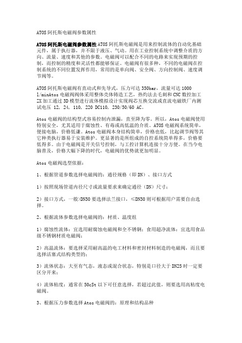
ATOS阿托斯电磁阀参数属性ATOS阿托斯电磁阀参数属性ATOS阿托斯电磁阀是用来控制流体的自动化基础元件,属于执行器,并不限于液压、气动。
用在工业控制系统中调整介质的方向、流量、速度和其他的参数。
电磁阀可以配合不同的电路来实现预期的控制,而控制的精度和灵活性都能够保证。
电磁阀有很多种,不同的电磁阀在控制系统的不同位置发挥作用,常用的是单向阀、安全阀、方向控制阀、速度调节阀等。
ATOS阿托斯电磁阀有直动式和先导式,压力可达350bar,流量可达1000l/minAtos电磁阀阀体采用整体壳体铸造工艺,热灼法去毛刺和CNC数控加工ZX加工通过3D模型进行流体模拟设计实现阀芯互换交流或直流电磁铁厂内测试电压 12, 24, 110, 220 DC110, 230/50/60 AC。
Atos电磁阀的结构型式容易控制内泄漏,直至降为零。
所以,Atos电磁阀使用特别安全,尤其适用于腐蚀性、有毒或高低温的介质。
ATOS电磁阀系统简单,便接电脑,价格低谦。
Atos电磁阀本身结构简单,价格也低,比起调节阀等其它种类执行器易于安装维护。
更显著的是所组成的自控系统简单得多,价格要低得多。
由于电磁阀是开关信号控制,与工控计算机连接十分方便。
在当今电脑普及,价格大幅下降的时代,电磁阀的优势就更加明显。
Atos电磁阀选型依据:1、根据管道参数选择电磁阀的:通径规格(即DN)、接口方式1)按照现场管道内径尺寸或流量要求来确定通径(DN)尺寸;2)接口方式,一般>DN50要选择法兰接口,≤DN50则可根据用户需要自由选择。
2、根据流体参数选择电磁阀的:材质、温度组1)腐蚀性流体:宜选用耐腐蚀电磁阀和全不锈钢;食用超净流体:宜选用食品级不锈钢材质电磁阀;2)高温流体:要选择采用耐高温的电工材料和密封材料制造的电磁阀,而且要选择活塞式结构类型的;3)流体状态:大至有气态,液态或混合状态,特别是口径大于DN25时一定要区分开来;4)流体粘度:通常在50cSt以下可任意选择,若超过此值,则要选用高粘度电磁阀。
漏电保护器的铭牌参数
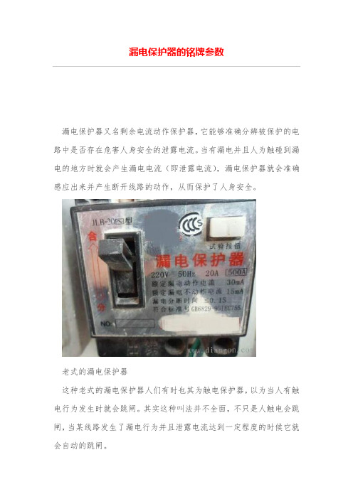
漏电保护器的铭牌参数漏电保护器又名剩余电流动作保护器,它能够准确分辨被保护的电路中是否存在危害人身安全的泄露电流。
当有漏电并且人为触碰到漏电的地方时就会产生漏电电流(即泄露电流),漏电保护器就会准确感应出来并产生断开线路的动作,从而保护了人身安全。
老式的漏电保护器这种老式的漏电保护器人们有时也其为触电保护器,以为当人有触电行为发生时就会跳闸。
其实这种叫法并不全面,不只是人触电会跳闸,当某线路发生了漏电行为并且泄露电流达到一定程度的时候它就会自动的跳闸。
铭牌上的各种数据分别为:220V表示额定电压;50Hz表示额定频率;20A表示额定电流。
500A表示额定极限分断能力(对于这款的保护器是否具有短路保护及过载保护,不是很清楚,如有知道的,还请告知一下)。
30mA表示额定漏电动作电流;15mA表示额定漏电不动作电流。
<=0.1s表示额定分断时间不大于0.1秒。
额定漏电动作电流30mA意思是当被保护的电路中的漏电电流达到了30mA 或者超过了30mA,保护器就是要动作的,即将电路给断开,被保护的电路中就没有电了。
额定不动作电流15mA可能你就会怀疑了,既然有了动作电流为什么还要不动作电流呢。
其实是因为即使我们在正常使用各种电器的时候,电路中因为各种原因,多多少少的也会有泄露电流,所以规定了15mA作为一个上限,即当电路中的泄露电流长时间小于15mA时,保护器是不动作的。
设置一个这个电流,能保证我们正常使用各种电器,不然一有泄露电流就跳闸,我们就没法好好用电了。
漏电分断时间<=0.1s说的是当泄露电流达到或者超过30mA时开始到保护器跳闸成功所用的时间不超过0.1秒,这么短的时间内就成功跳闸能够保护人身安全的。
微波炉磁控管型号解读

微波炉磁控管型号解读随着科技的不断发展,现代家庭中微波炉已经成为一种不可或缺的家电之一。
而作为微波炉的核心部件,磁控管的型号选择则是微波炉操作和效果的重要因素之一。
在本文中,我们将为您详细解读微波炉磁控管的型号,希望能对您选购微波炉有所帮助。
第一部分:磁控管的基本原理磁控管的英文名为“Magnetron”,是微波发生器的核心部件之一,它的主要作用是将电能转化为微波能或者其他高频电磁波。
在微波炉中,磁控管能够将电压和电流的能量转化为微波功率,从而使微波炉能够产生微波并进行加热。
在磁控管内部,电场和磁场的相互作用产生了高频场,从而使中心的阳极向外辐射微波。
通常情况下,磁控管的工作电压在 1KV~10KV 左右,而电流则在 100mA ~ 500mA 之间,因此可以产生高达 800W 的功率。
第二部分:磁控管的型号解读1、型号规则在磁控管的型号中,通常会包含以下信息:• 产地信息在磁控管的型号中,通常会包含产地信息,如日本、韩国、美国等,每一个国家的生产技术和质量标准都不同。
• 额定功率在磁控管的型号中,通常会包含额定功率,如 600W、700W、800W 等,这是磁控管能够输出的最大功率。
• 工作电压在磁控管的型号中,通常会包含工作电压,如2100V、2300V、2500V 等,这是磁控管能够承受的最大电压。
• 频率在磁控管的型号中,通常会包含频率,如 2450MHz,这是微波炉的工作频率,磁控管需要与之匹配。
2、型号选择对于用户来说,选择合适的磁控管型号是非常重要的。
在选择时,需要考虑以下几个因素:• 适配微波炉制造商不同的微波炉制造商使用的磁控管型号可能并不完全一样,因此需要注意选购能够适配你家微波炉的型号。
• 前置功率前置功率一般指微波炉的最大输出功率,在选购磁控管时需要根据微波炉的前置功率来选择。
如果磁控管的功率过低,则不同附加电子器件(如变压器)来提高前置功率,这是对微波炉效果有很大影响的。
美特顿机械保护电流保护器说明书

Eaton 269471Eaton Moeller® series EMT6 Thermistor overload relay formachine protection, 1N/O+1N/C, 24-240VAC/DC, with reclosing lockoutGeneral specificationsEaton Moeller® series EMT6 Thermistor overload relay269471EMT6-KDB4015082694715103 mm 83 mm 23 mm 0.132 kgCSA File No.: 12528 IEC/EN 60947 CSA-C22.2 No. 14 IEC/EN 61000-4-3 CSACSA Class No.: 3211-03 IEC/EN 60947-8 IEC/EN 61000-4-2 CE UL 508UL File No.: E29184 ULUL Category Control No.: NKCR VDE 0660 EN 55011Product NameCatalog NumberModel Code EANProduct Length/Depth Product Height Product Width Product Weight CertificationsScrew connectionManual resetNotifications of mains and faults via LED display Short-circuit in the sensor cableTest function via separate buttonExternal reset possibleManual or remote resetting0 °C0 °C IP20As requiredIII3EMT6 thermistor overload relay for machine protectionFinger and back-of-hand proof, Protection against direct contact when actuated from front (EN 50274)6000 V AC4000 V AC250 V AC, Between the contacts, According to EN 61140250 V AC, Between the contacts and power supply, According to EN 6114010 g, Mechanical, according to IEC/EN 60068-2-27, Half-sinusoidal shock 10 msAC/DC-25 °C 60 °C 25 °C 45 °C 8 kV1 kV, Signal cable2 kV, Supply cableAccording to IEC/EN 61000-4-46 kV, Electrostatic discharge (ESD)Electric connection typeFunctionsTemperature measuring range - min Temperature measuring range - max Degree of protectionMounting positionOvervoltage categoryPollution degreeProduct categoryProtectionRated impulse withstand voltage (Uimp) Safe isolationShock resistanceVoltage typeAmbient operating temperature - minAmbient operating temperature - maxAmbient operating temperature (enclosed) - min Ambient operating temperature (enclosed) - max Air dischargeBurst impulse Contact discharge Electromagnetic fields45 °C85 °CDamp heat, cyclic, to IEC 60068-2-30 Damp heat, constant, to IEC 60068-2-783 V/m at 1.4 - 2 GHz (according to IEC EN 61000-4-3)1 V/m at 2.0 - 2.7 GHz (according to IEC EN 61000-4-3)10 V/m at 80 - 1000 MHz (according to IEC EN 61000-4-3) 10 V (according to IEC/EN 61000-4-6)Class B (EN 55011)2 kV, symmetrical, power pulses (Surge), EMCAccording to IEC/EN 61000-4-5, power pulses (Surge), EMC 4 kV, asymmetrical, power pulses (Surge), EMC1 x (0.5 - 2.5) mm², flexible with ferrule1 x (0.5 - 2.5) mm², solid2 x (0.5 - 1.5) mm², flexible with ferrule20 - 14 AWG, solid or stranded2 x (0.5 - 1.5) mm², solidM3.5, Terminal screw2, Terminal screw, Pozidriv screwdriver1 x 6 mm, Terminal screw, Standard screwdriver 1.2 Nm, Screw terminals 6 A0.85 - 1.1 V x Uₑ2 W at DC3.5 VA at AC24 V240 V24 V240 V24 V240 V400 V3 A at AC-14, 380 V 400 V 415 V (NC) 1 A at AC-15, 300 V (NC)3 A at AC-14, 400 V (NC)Ambient storage temperature - minAmbient storage temperature - max Climatic proofing Immunity to line-conducted interference Radio interference classSurge ratingTerminal capacityScrew size Screwdriver size Tightening torque Conventional thermal current ith of auxiliary contacts (1-pole, open)Pick-up voltagePower consumptionRated control supply voltage (Us) at AC, 50 Hz - minRated control supply voltage (Us) at AC, 50 Hz - maxRated control supply voltage (Us) at AC, 60 Hz - minRated control supply voltage (Us) at AC, 60 Hz - maxRated control supply voltage (Us) at DC - minRated control supply voltage (Us) at DC - maxRated insulation voltage (Ui)Rated operational current (Ie)3 A at AC-14, 300 V (NO) 1 A at AC-15, 300 V (NO)1 A at AC-15, 380 V 400 V 415 V (NO) 3 A at AC-15, 220 V 230 V 240 V 3 A at AC-14, 300 V (NC)3 A at AC-14, 380 V 400 V 415 V (NO) 3 A at AC-15, 220 V 230 V 240 V (NO) 1 A at AC-15, 380 V 400 V 415 V (NC) 3 A at AC-15, 220 V 230 V 240 V (NC)240 V1600 ΩMax. 6 A gG/gL, Fuse, Contacts3600 Ω600 V110 W0 W 0 W 0 A0.8 W EMR6 - EMT6 - ETR4 brochure DA-DC-00003984.pdf DA-DC-00004614.pdf eaton-tripping-emt6-thermistor-overload-relay-characteristic-curve.eps eaton-tripping-thermistor-relay-emt6-dimensions.eps eaton-tripping-devices-relay-emt6-thermistor-overload-relay-dimensions.epseaton-tripping-devices-relay-emt6-thermistor-overload-relay-3d-drawing-002.eps Rated operational voltage (Ue) - max Reset resistance Short-circuit protection rating Trip resistance Voltage rating - max Number of contacts (change-over contacts)Number of contacts (normally closed contacts)Number of contacts (normally open contacts)Equipment heat dissipation, current-dependent PvidHeat dissipation capacity PdissHeat dissipation per pole, current-dependent PvidRated operational current for specified heat dissipation (In)Static heat dissipation, non-current-dependent Pvs BrochuresCertification reports Characteristic curveDrawingseCAD modelEaton Corporation plc Eaton House30 Pembroke Road Dublin 4, Ireland © 2023 Eaton. All rights reserved. Eaton is a registered trademark.All other trademarks areproperty of their respectiveowners./socialmediaETN.EMT6-KDB eaton-emt6-thermistor-overload-motor-protection-relays-instruction-leaflet-il03407100z.pdf MN03407006Z_DE_EN DA-CS-emt6_db DA-CD-emt6_db eaton-tripping-devices-auto-mode-emt6-thermistor-overload-relay-wiring-diagram.epsInstallation instructionsManuals and user guides mCAD model Wiring diagrams。
天津市百利纽泰克20KV系列产品介绍

外形图
标记 处数 更改文件号 设 校 审 工 计 对 核 艺 日 期 审 签 定 字 日期 标准化
天津市百利纽泰克 电气科技有限公司
产品技术条件
1.型号含义
U R E D - 20 额 定 电 压 kV 可带熔断器套管式 一 端 绝 缘 带 熔 断 器 套 管 式 电压互感器
2.额定电压、准确级、额定负荷
额定电压比(KV)
准确级
0.2/3P(6P)
额定负荷(VA)
20/50
COSφ
20:√3/0.1:√3,0.1:3 0.5/3P(6P) 40/50
0.8
UNEZ2-20
产品介绍
技术要求
铭
牌
1a
1n
2a 2n da dn
产 品 外 形 图
图 样 标 记 重量 比例 共 张 第 张
A
N
外 形 图
研发部 质量部 计划采购 标记 处数 更改文件号 设 校 审 工 计 对 核 艺 日 期 审 签 定 字 日期
UNEZ2-20
标准化
天津市百利纽泰克 电气科技有限公司
额定负荷(VA)
10~30
15~30
AS24/185J/3(-2)代CT
产品介绍
产品外形图
0 TN .3 00 .0 92 .1 ~ 2 P1 P2
A S2 4/ 18 5J /3 (- 2)
外 形 图 0TN.300.092.1 0TN.300.092.2 浇 注 体 5TN.779.135.1 5TN.779.135.2 装 配 1TN.764.047.1 1TN.764.047.2 I1n( A) ≤ 1250 1500~ 2500
0.8
URED3-20
TMP320LC2401AVFA资料
Description . . . . . . . . . . . . . . . . . . . . . . . . . . . . . . . . . . . . . 4 TMS320x240xA Device Summary . . . . . . . . . . . . . . . . . 5 Functional Block Diagram of the 2407A DSP Controller . . . . . . . . . . . . . . . . . . . . . . . . . . . . . . 6 Pinouts . . . . . . . . . . . . . . . . . . . . . . . . . . . . . . . . . . . . . . . . 7 Pin Functions . . . . . . . . . . . . . . . . . . . . . . . . . . . . . . . . . . 11 Memory Maps . . . . . . . . . . . . . . . . . . . . . . . . . . . . . . . . . 21 Peripheral Memory Map of the 2407A/2406A . . . . . . . 29 Device Reset and Interrupts . . . . . . . . . . . . . . . . . . . . . 30 DSP CPU Core . . . . . . . . . . . . . . . . . . . . . . . . . . . . . . . . 34 TMS320x240xA Instruction Set . . . . . . . . . . . . . . . . . . . 34 Scan-Based Emulation . . . . . . . . . . . . . . . . . . . . . . . . . . 34 Functional Block Diagram of the 2407A DSP CPU . . 35 Internal Memory . . . . . . . . . . . . . . . . . . . . . . . . . . . . . . . . 42 Peripherals . . . . . . . . . . . . . . . . . . . . . . . . . . . . . . . . . . . . 45 Event Manager Modules (EVA, EVB) . . . . . . . . . . . . 45 Enhanced Analog-to-Digital Converter (ADC) Module . . . . . . . . . . . . . . . . . . . . . . . . . . . . 49 Serial Communications Interface (SCI) Module . . . . 53
AUMA 说明手册 中英文对照文稿-world版可编辑
操作说明手册的封面内容翻译(中英文对照):Multi-turnactuators万向驱动装置SA07.1-SA48.1(产品型号)SAR07.1-SAR30.1(产品型号)AUMANORM(AUMA是这个阀门生产厂的品牌名称)AUMA标准Operationinstructions(操作手册)目录内容:Scopeoftheseinstructions:本手册内容介绍的范围包括:Theseinstructionsarevalidformulti-turnactuatorsforOpen-closeduty,SA07.1-SA48.1,andmul ti-turnactuatorsformodulatingduty,SA07.1-SA30.1.本手册的说明适应型号为SA07.1-SA48.1、具有开启-关闭功能系列的万向驱动装置和型号为SA07.1-SA30.1、具有调节功能系列的万向驱动装置有效。
Theseoperationsinstructionsareonlyvalidfor“clockwiseclosing”,i.e.drivenshaftturnsclockwisetoclosethevalve.这些操作说明只对"顺时针关闭"有效,即:驱动轴顺时针转动关闭阀门。
.Safetyinstructions(安全说明)1.1Rangeofapplication(应用的范围)AUMQmulti-turnactuatorsaredesignedfortheoperationofindustrialvalves,e.g,globevalve s,butterflyvalvesandballvalves.Forotherapplications,pleaseconsultus.AUMAisnotliablefo ranyapplications.Suchriskliesentirelywiththeuser.AUMQ万向驱动装置是为工业用阀所设计的,例如:工业生产常用球瓣阀,蝶阀和球阀。
奥太电流调节参照表

奥太电流调节参照表【原创实用版】目录1.奥太电流调节参照表的概述2.奥太电流调节参照表的内容3.奥太电流调节参照表的应用4.奥太电流调节参照表的注意事项正文一、奥太电流调节参照表的概述奥太电流调节参照表是一种用于调整电路中电流大小的工具,主要应用于工业自动化领域。
通过参考表中的数据,工程师可以更方便、准确地设置电流值,从而实现对电路中电流的有效控制。
二、奥太电流调节参照表的内容奥太电流调节参照表主要包括以下几个部分:1.电流单位:通常以安培(A)为单位,也有毫安(mA)和微安(μA)等其他单位。
2.电流等级:电流等级分为多个档位,不同档位对应不同的电流范围。
3.电流调节方式:参照表中提供了多种电流调节方式,如手动调节、自动调节等。
4.电流误差:电流误差是指实际电流与设定电流之间的差值,参照表中会标注不同电流等级下的电流误差。
5.适用范围:参照表会标明该表适用于哪些电路和设备。
三、奥太电流调节参照表的应用奥太电流调节参照表在工业自动化领域有广泛的应用,如:1.控制电机转速:通过调整电机供电电流的大小,可以实现对电机转速的控制。
2.控制加热设备的温度:通过调整加热设备的电流,可以实现对设备温度的控制。
3.控制传感器的灵敏度:传感器的工作电流会影响其灵敏度,通过调整电流可以优化传感器的性能。
四、奥太电流调节参照表的注意事项在使用奥太电流调节参照表时,需要注意以下几点:1.选择合适的电流等级:根据实际应用需求选择合适的电流等级,以保证电路正常工作。
2.注意电流误差:电流误差会影响电路的性能,因此在选择电流调节方式时,要充分考虑电流误差的影响。
3.遵守安全规定:在操作过程中,要遵守相关安全规定,防止触电等安全事故的发生。
爱达顿商品说明书:温控系统断路器

V1-T6-16Air Conditioning DisconnectsAir Conditioning Disconnects6.1Air Conditioning DisconnectsProduct Description . . . . . . . . . . . . . . . . . . . . . . . . . . . . . . . . . . . . . . .V1-T6-2Application Description. . . . . . . . . . . . . . . . . . . . . . . . . . . . . . . . . . . . .V1-T6-2Features, Benefits and Functions . . . . . . . . . . . . . . . . . . . . . . . . . . . . .V1-T6-3Standards and Certifications. . . . . . . . . . . . . . . . . . . . . . . . . . . . . . . . .V1-T6-3Product Selection . . . . . . . . . . . . . . . . . . . . . . . . . . . . . . . . . . . . . . . . .V1-T6-4Cross-Reference. . . . . . . . . . . . . . . . . . . . . . . . . . . . . . . . . . . . . . . . . .V1-T6-6Technical Data and Specifications. . . . . . . . . . . . . . . . . . . . . . . . . . . . .V1-T6-7Dimensions. . . . . . . . . . . . . . . . . . . . . . . . . . . . . . . . . . . . . . . . . . . . . .V1-T6-7LearnOnlineVolume 1—Residential and Light Commercial, CA08100002ETab 6—Air Conditioning DisconnectsRevision date Section Change page(s)Description02/19/2018All All Change to revision date to match print version, February 201866.1Air Conditioning DisconnectsFused, Unfused and Molded Case SwitchComplete Line of Fused, Unfused and MoldedCase Switch Type Air Conditioning DisconnectsAir Conditioning DisconnectsContentsDescription PageFeatures, Benefits and Functions . . . . . . . . . . . . . V1-T6-3Standards and Certifications. . . . . . . . . . . . . . . . . V1-T6-3Product Selection . . . . . . . . . . . . . . . . . . . . . . . . . V1-T6-4Cross-Reference. . . . . . . . . . . . . . . . . . . . . . . . . . V1-T6-6Technical Data and Specifications. . . . . . . . . . . . . V1-T6-7Dimensions. . . . . . . . . . . . . . . . . . . . . . . . . . . . . . V1-T6-7Product DescriptionAn air conditioningdisconnect (ACD) is adisconnect located betweena loadcenter (distributionpanel) and air conditioner.Eaton’s ACD product lineprovides an installer or repairpersonnel with a visibledisconnecting means whenperforming maintenance.ACDs are also known asdisconnects, pullouts or airconditioning switches.Non-fused pullout andmolded case switch devicesprovide personnel with avisible ON-OFF disconnectingmeans. While fused pulloutunits also perform thisfunction, they also provide anadditional level of protectionfor the air conditioner.Fused and non-fused devicesare of a pullout design, wherethe user physically removesor “pulls out” a tab to breakthe electrical connection.A molded case switch issimilar to a light switch wherethe user “switches” theunit to the indicatedON-OFF position.Fused and Non-FusedPullouts●ON/OFF control providedby a pullout handle●Pullout handle can beconveniently stored in thecompartment in the OFFposition, helping to preventthe handle from beingmisplaced●Protective shield cannot beremoved until the pullouthandle is removed,disconnecting the powerMolded Case Switch●Rugged molded caseconstruction in adisconnect switch thatlooks like a circuit breakerbut operates like anordinary householdlight switch●Plug-in molded case switch(included) eliminates theneed for pullout handles●No need for replacementpullout handles due to lossor theftApplication DescriptionThe most widely usedapplication for ACDs is forresidential and lightcommercial air conditioningunits. An ACD is installedoutdoors, in visible proximityto the air conditionercondensing unit. ACDs arealso found in use with heatpumps, swimming pools,spas, whirlpools and pumphouses, and meet 2008NEC Article 422.31 (B)requirements for servicingelectric water heaters.Metallic enclosures aregalvanized steel and areinstalled in various locations.Non-metallic enclosures are aplastic (polycarbonate)enclosure commonly used incoastal or salt-water areas.V1-T6-2V1-T6-366.1Air Conditioning DisconnectsFused, Unfused and Molded Case SwitchFeatures, Benefits and Functions●Single-phase, two-wire, 240 Vac and three-phase, three-wire, 240 Vac ●NEMA 3R outdoor enclosures offered in metallic andnon-metallic versions ●Easy-to-remove high-strength protective shield for easier wiring and mounting●Easy-to-remove front cover (no screws or fasteners to remove)●1-inch knockouts on the bottom, back and side of unit●Copper-rated line and load lugs that are easily accessible●Ample wiring space for mounting with a stud gun (single keyhole, two- or three-point mounting)●Fused devices are service entrance ratedNote: Fused non-metallic units require the addition of GB4NM ground bar to obtain a Service Entrance rating.●Horsepower rated (10 hp maximum at 240 Vac)●Padlockable door provision for safety and reduction of tampering●Metallic enclosures are bottom entry and exit only ●Non-metallic enclosures have knockouts and a hub provision for top access ●Non-metallic enclosures have a single unit door and protective shield for installer convenience ●Non-metallic enclosures are durable and provide excellent resistance to climate changes●Factory-installed tamper-resistant/weather-resistant receptacles are available as an option on some productsStandards and Certifications●UL listed File No. E132354, E143893, E196365Contact Eaton for details and part numbers for CSAapproved units.66.1Air Conditioning DisconnectsFused, Unfused and Molded Case SwitchProduct SelectionNon-Fused PulloutsFused PulloutsFor Service Entrance applications, see footnotes below.Molded Case SwitchNotes1 For replacement pullout head, order part number 96-3258-4.2 To obtain a Service Entrance Rating, the addition of a DPFG (ground bar kit) is required.3 For replacement molded case switch, order part number BR260NA.MainAmpereRatingMaximum hp Rating Wire SizeRange Cu/Al60 °C or 75 °CCatalogNumber120 V240 VGalvanized Steel60—10#14–3DPU222R 1Non-Metallic/Polycarbonate Enclosure60—10#14–2ACD222URNM-A2 1MainAmpereRatingMaximum hp Rating Wire SizeRange Cu/Al60 °C or 75 °CCatalogNumber120 V240 VGalvanized Steel30 223#14–3DPF221R 160 2310#14–3DPF222R 1Non-Metallic3023#14–2ACD221RNM-A2 160310#14–2ACD222RNM-A2 1MainAmpereRatingMaximum hp Rating Wire SizeRange Cu/Al60 °C or 75 °CCatalogNumber120 V240 VGalvanized Steel60—10#14–3DPB222R 3Non-Metallic/Polycarbonate Enclosure60—10#14–2B60NARNM-A2 3 DPU222RDPF222RDPB222RV1-T6-4V1-T6-566.1Air Conditioning DisconnectsFused, Unfused and Molded Case SwitchACD with 20 Ampere Ground Fault Receptacle 1ACD with 15 Ampere Ground Fault Receptacle 13Notes1 Factory-installed GFCI receptacle.2 Includes weather-resistant/tamper-resistant receptacles to meet 2008 NEC Article 406.8 (A) and 406.11 requirements.3 NEC permits the maximum receptacle rating of a 15 A circuit to be 15 A.Main Ampere RatingMaximum hp Rating Wire Size Range Cu/Al 60 °C or 75 °CCatalog Number120 V240 VNon-Fused Pullouts 60—10#14–3DPU222RGF20WTST 260—10 #14–3 DPU222RGF20STFused Pullouts 3023#14–3DPF221RGF20WTST 23023#14–3DPF221RGF20ST 60310#14–3DPF222RGF20WTST 260310#14–3DPF222RGF20STMain Ampere RatingMaximum hp Rating Wire Size Range Cu/Al 60 °C or 75 °CCatalog Number120 V240 VNon-Fused Pullouts 60—10 #14–3 DPU222RGF15ST 60—10#14–3DPU222RGF15WTST 2Fused Pullouts 3023#14–3DPF221RGF15ST 3023#14–3DPF221RGF15WTST 260310#14–3DPF222RGF15ST 60310#14–3DPF222RGF15WTST 2DPU222RGF20DPU222RGF1566.1Air Conditioning DisconnectsFused, Unfused and Molded Case SwitchThree-Phase Non-Fused ACDCross-ReferenceCross-ReferenceNote1Eaton Quick Pro SM designated item.MainAmpereRatingMaximum hp RatingWire SizeRange Cu 75 °CCatalogNumber240 V480 V6015 30#14–4DPU362RADPU362ADescriptionCatalog NumberEaton SquareD®GE®Siemens®(Murray®)Milbank Midwest Metallic/Galvanized Steel Enclosure30 A fused DPF221R—TF30R WF2030U3830U035F2 60 A fused DPF222R—TF60R WF2060U3860U065F1 60 A non-fused DPU222R—TFN60R—U3800U065P010 60 A non-fused compact design DPU222R——WNFC2060——60 A molded case switch DPB222R QO200TR TNA60R1WNAS2060—U065NA1 60 A non-fused with ground fault receptacle DPU222RGF20ST—TFN60RGFR WN2060GFCI U3822-20GR U065P010 30 A fused with ground fault receptacle DPF221RGF20ST——WF2030GFCI—U035F010 60 A fused with ground fault receptacle DPF222RGF20ST——WF2060GFCI—U065F010 60 A non-fused with 1/2-inch wire harness DPU222R12W 1—————60 A non-fused with 3/4-inch wire harness DPU222R34W 1—————60 A three-phase 600 V molded case switch DPU362RA————U0653F Non-Metallic/Polycarbonate Enclosure30 A fused ACD221RNM-A2—TPF30R WF2030PL—P035F60 A fused ACD222RNM-A2—TPF60R WF2060PL—P065F60 A non-fused ACD222URNM-A2—TPN60R1WN2060PL—P065P1 60 A molded case switch B60NARNM-A2QO200TRNM TPNA60R1WNAS2060PL—P065NA1 30 A fused with 15 A ground fault receptacle DPF221RGF15WRTRST—————30 A fused with 20 A ground fault receptacle DPF221RGF20WRTRST—————60 A fused with 15 A ground fault receptacle DPF222RGF15WRTRST—————60 A fused with 20 A ground fault receptacle DPF222RGF20WRTRST—————60 A non-fused with 15 A ground fault receptacle DPU222RGF15WRTRST—————60 A non-fused with 20 A ground fault receptacle DPU222RGF20WRTRST———U3822-20GWR—V1-T6-6V1-T6-766.1Air Conditioning DisconnectsFused, Unfused and Molded Case SwitchTechnical Data and Specifications●10,000 amperes rms symmetrical interrupting rating●Horsepower rated●Fusible and non-fusible pullout and molded case switch designs●30 and 60 amperes available in fusible●60 amperes available in non-fusible and molded case switch●Class H fuse clips provided on fusible pullout design ●WTST (weather-resistant/ tamper-resistant with ground fault self-test) receptacle availableDimensionsApproximate Dimensions in Inches (mm)Dimensions and Shipping Carton InformationNote1Eaton Quick Pro designated item.Catalog NumberCarton QuantityDimensions in Inches (mm)Weight Lbs (kg)HeightWidthDepthMetallic/Galvanized Steel Enclosure DPF221R 108.70 (220.9) 5.40 (137.2) 3.15 (80.0)27 (12)DPF222R 108.70 (220.9) 5.40 (137.2) 3.15 (80.0)27 (12)DPU222R 108.70 (220.9) 5.40 (137.2) 3.15 (80.0)27 (12)DPB222R 108.60 (218.4) 5.30 (134.6) 3.74 (95.0)34 (15)DPU222R12W 1114.75 (374.6)12.50 (317.5) 4.00 (101.6) 6 (3)DPU222R34W 1114.75 (374.6)12.50 (317.5) 4.00 (101.7) 6 (3)DPU222RGF20ST 113.00 (330.2)7.50 (190.5) 4.75 (120.7)8 (4)DPF221RGF20ST 113.00 (330.2)7.50 (190.5) 4.75 (120.7)8 (4)DPF222RGF20ST 113.00 (330.2)7.50 (190.5) 4.75 (120.7)8 (4)DPU222RGF15ST 113.00 (330.2)7.50 (190.5) 4.75 (120.7)8 (4)DPF221RGF15ST 113.00 (330.2)7.50 (190.5) 4.75 (120.7)8 (4)DPF222RGF15ST 113.00 (330.2)7.50 (190.5) 4.75 (120.7)8 (4)DPF221RGF15WTST 113.00 (330.2)7.50 (190.5) 4.75 (120.7)8 (4)DPF221RGF20WTST 113.00 (330.2)7.50 (190.5) 4.75 (120.7)8 (4)DPF222RGF15WTST 113.00 (330.2)7.50 (190.5) 4.75 (120.7)8 (4)DPF222RGF20WTST 113.00 (330.2)7.50 (190.5) 4.75 (120.7)8 (4)DPU222RGF15WTST 113.00 (330.2)7.50 (190.5) 4.75 (120.7)8 (4)DPU222RGF20WTST 113.00 (330.2)7.50 (190.5) 4.75 (120.7)8 (4)DPU362R18.60 (218.4)5.30 (134.6)3.74 (94.9)4 (2)Non-Metallic/Polycarbonate Enclosure ACD221RNM-A210 8.63 (219.0) 6.26 (159.0) 4.33 (109.9)15 (7)ACD222RNM-A210 8.63 (219.0) 6.26 (159.0) 4.33 (109.9)15 (7)ACD222URNM-A210 8.63 (219.0) 6.26 (159.0) 4.33 (109.9)15 (7)B60NARNM-A2108.63 (219.0)6.26 (159.0)4.33 (109.9)18 (8)66.1Air Conditioning DisconnectsFused, Unfused and Molded Case Switch Approximate Dimensions in Inches (mm)DPF221R, DPF222R, DPU222R, DPU222R12W and DPU222R34WV1-T6-8V1-T6-966.1Air Conditioning DisconnectsFused, Unfused and Molded Case SwitchApproximate Dimensions in Inches (mm)ACD221RNM-A2, ACD222RNM-A2, ACD222URNM-A2 and B60NARNM-A2DPB222R and DPU362Afor 0.75 (19.1)or 1.00 (25.4)Conduit66.1Air Conditioning DisconnectsFused, Unfused and Molded Case SwitchApproximate Dimensions in Inches (mm)DPU222RGF20, DPF221RGF20, DPF222RGF20, DPU222RGF15, DPF221RGF15, DPF222RGF15, DPF221RGF15WTST, DPF221RGF20WTST, DPF222RGF15WTST, DPF222RGF20WTST, DPU222RGF15WTST and DPU222RGF20WTSTV1-T6-10。
美国电闸厂Eaton公司的产品说明书

Eaton SPSC083VEAXX2SEaton Power Defense SB, Standard, 800 A, 100 kA, 3-Pole, Fixed,PXR25LSIGAM, C083VEAXX2SGeneral specificationsEaton Magnum low voltage power circuitbreakerSPSC083VEAXX2S78668976324414.6 in16.8 in16.2 in118 lbSABA Listed NEMA Compliant CE Marked CCC Marked ANSIUL ListedCSA CertifiedDNV GL CertifiedLloyd's Register Certified ABS CertifiedKEMA CertifiedProduct Name Catalog NumberUPCProduct Length/Depth Product Height Product Width Product Weight Compliances Certifications800 AUL 891StandardThree-polePower Defense SB UL 891 Standard Magnum PXR25Fixed Three-pole800 A 600 VAC Fixed 100 kA100 kA 800 A 800 A 600 VAC Zone selective interlocking application paperMagnum circuit breakers with Power Xpert Release trip units product aid Selevctive coordination application paper - IA0120000E3Magnum PXR and PD-SB double and double narrow frame UL Certificate of ComplianceMagnum PXR and PD-SB standard and narrow frame UL Certificate of ComplianceAmperage Rating Application FrameNumber of poles Type Application FrameSeriesTrip TypeMounting Method Number of polesRated uninterrupted current (Iu) Voltage rating Mounting Method Interrupt ratingInterrupt ratingAmperage RatingRated uninterrupted current (Iu) Voltage rating Application notes Brochures Catalogs Certification reportsEaton Corporation plc Eaton House30 Pembroke Road Dublin 4, Ireland © 2023 Eaton. All Rights Reserved. Eaton is a registered trademark.All other trademarks areproperty of their respectiveowners./socialmediaMicrosoft Word - Power Xpert Protection Manager Quick Start Guide.docxPower Xpert Release trip unit for Magnum PXR circuit breakers PXR 20/25 user manualMagnum PXR low voltage power circuit breakers user manual Power Xpert Protection Manager x64 22.6 1 Power Xpert Protection Manager x32 22.06 1 Eaton Specification Sheet - SPSC083VEAXX2S Low voltage circuit breakers guide spec Magnum PXR 20/25 electronic trip units time current curves Cyber security white paperSafer by design: arc energy reduction techniques Molded case and low-voltage power circuit breaker healthManuals and user guidesSoftware, firmware, and applications Specifications and datasheetsTime/current curvesWhite papers。
techrom 说明书

techrom 说明书产品型号:TCS-20所属分类:粘度计产品时间:2021-03-26简要描述:日本techrom用于热脱附装置的管调节器TCS-20 使用热解吸装置(热分解)时,调节收集管(吸附管)的工作是最基本的工作。
TCS-20是专yong设备,可同时调节(燃烧)多达20个加热和解吸设备中使用的收集管。
更轻松,更有效地调节收集管使用热解吸装置(热分解)时,调节收集管(吸附管)的工作是最基本的工作。
TCS-20是专yong设备,可同时调节(燃烧)多达20个加热和解吸设备中使用的收集管。
z理想的多级温升可减少填料损坏。
卧式实现了热量分布小的加热炉,并实现了理想的调节。
除了通过升温程序进行调节外,还可以通过采用冷却风扇在短时间内冷却加热炉(烤箱)。
免工具管安装是带O型圈的一键式安装。
如果将压力调节为0.1MPa,则所有管中的流速相同。
(约45㎖/分钟)根据应用定制由于它是可移动的容器,因此可以替换为各种规格。
除了容器之外,您还可以选择加热炉(长,短)和冷却风扇(标准,静音型),因此可以根据您的应用进行自定义。
日本techrom用于热脱附装置的管调节器TCS-20主要规格散热功能:是的(370℃→50℃约20分钟)加热温度:室温+50-370℃流量设定范围:0-100毫升/分钟电源:AC100V 5A使用的气体:N2推荐纯度99.999%以上能量消耗;450瓦容器;1/4管容器(用于20件)x 1或6 mm管容器(用于20件)x 1 1/4管容器(用于10个)6毫米管容器(用于20个)选项:6mm管容器(用于10个)组合容器(用于1/4 10件6mm 10件)合并容器(自定义)*组合容器(自定义)可根据客户要求进行更改。
(最多20个)。
COT-UN5200A 产品说明书
COT-UN5200A产品说明书文档版本:V20190215 目录1 功能特点 (3)2 快速入门 (4)2.1 硬件连接 (4)2.2 网络环境 (4)2.3 设备默认参数 (6)2.4 传输测试 (7)3 产品概述 (8)3.1 技术指标 (8)3.2 外形尺寸(毫米) (9)3.3 接口定义 (10)3.4 S1跳线功能 (11)4 网络基础功能介绍 (12)4.1 IP地址/子网掩码/网关 (12)4.2 网页配置 (13)4.3 指示灯状态 (14)4.4 网络工作模式 (14)4.4.1工作模式:TCP Server (15)4.4.2工作模式:TCP Client (15)4.4.3工作模式:UDP Client (16)4.4.4工作模式:UDP Server (17)4.5 串口功能 (17)4.6特色功能 (18)4.6.1 心跳包功能 (18)4.6.2 Modbus网关功能 (18)4.6.3 注册包功能 (18)4.6.4 数据路由功能 (19)5 AT指令配置 (21)1 功能特点n采用高速高性能ARM处理器,工业级工作温度,硬件TCP/IP协议栈稳定可靠n DC9-32V宽工作电压,多重保护,正反接自适应n10/100Mbps自适应网络,支持TCP Server、TCP Client、UDP Server、UDP Client 多种工作模式n内置中英文网页,可通过WEB网页进行参数配置n支持RS232和RS485端口,两个端口可以同时独立工作,互不影响n支持RTS/CTS硬件流控功能n串口波特率支持1200bps~115.2Kbps;支持None、Odd、Even校验方式n支持Modbus网关功能,工业现场使用方便n RJ45带Link/Data指示灯,网口内置隔离变压器,1.5KV电磁隔离n允许用户自定义MAC地址n支持静态IP地址和DHCP自动获取IP地址n支持keepalive机制,可快速探查死连接等异常并快速重连n支持修改密码,可用于网页参数修改,更安全n支持路由功能,可选择网络数据、串口数据的传输方向[ 产品图示]2 快速入门COT-UN5200A模块用于实现串口到以太网口的数据的双向透明传输,用户无需关心具体细节,模块内部完成协议转换。
数字式市电同步无缝切换光伏逆变器介绍

产品功能
产品参数:
• 额定输入电压:DC48V; • 工作范围: DC40-60V; • 额定输出电压:AC220V ; • 输出电压范围:AC220V﹢5%/﹣5%; GB/T 20321.1 5.3 • 额定频率:50HZ,精度±0.005HZ GB/T 20321.1 5.4 ; • 同步锁相范围:48.5-51.5HZ; • 负载功率因素:±90° ; • 输出电流谐波总量:≤2% GB/T 20321.1 5.5 ; • 输入欠压报警:DC42V ; • 输入欠压保护:DC40V GB/T 20321.1 5.8.C ;
产品功能
产品参数:
•使用海拔高度:<3500m GB/T 20321.1 5.2.C ; • 工作温度范围:-20℃至+45℃ ℃ GB/T 20321.1 5.2.A, GB/T 20321.1 11; • 体积长*高*宽:37cm*27cm*11cm; • 重量:8Kg; •输入接插件:SA120 120A/600V •交流输出接插件: •市电输入接插件: •外壳材质: 6065铝合金,表面本色阳极氧化 •强制风冷风机:DC8025HS(B)1 3000rpm 43.59CFM 噪音36db •防护等级: IP20 室内
开发背景
本产品要解决的主要问题是:
1. 解决普通逆变器在太阳能不足,需切换到市电时 带来的各种问题:切换时供电有断点,继电器有 火花等危害。增加了市电相位检测、同步模块, 采用先合后分的策略,使清洁能源与市电切换时 输出电压无断点,继电器触点无火花。
2.增加太阳能板充电控制管理模块,方便终端用户 直接使用,降低成本。
3.增加并机扩容功能,方便用户自行按需配置系统
开发背景
4.采用输入反接无损保护技术,避免用户自行安装
SmartEx AL系列 带剩余电流保护塑壳断路器(漏电)
额定绝缘电压Ui(V)
额定剩余动作电流 I△n(mA)
非延时型Ⅰ 非延时型Ⅱ
额定极限短路 分断能力Icu(kA) 400V AC
额定电流 (A)
6A
10A
16A
20A
20kA
25A
32A
40A
50A
63A
6A
10A
16A
20A
35kA
25A
32A
40A
50A
63A
产品编号 3极
AWG006R AWG010R AWG016R AWG020R AWG025R AWG032R AWG040R AWG050R AWG063R
800aintelligentelectricexpertsservicechinaelectricpower0204141517243030313132364344475355smartex01目录contents产品概述产品选型脱扣方式及附件代号型号含义附件技术参数保护特性剩余电流保护动作特性功率损耗热动脱扣器额定工作电流随环境变化的降容系数特性曲线外形及安装尺寸附件列表内部附件外部附件使用及维护安全距离产品概述工作环境及安装条件剩余电流保护型式符合标准smartexal系列带剩余电流保护塑壳断路器以下简称断路器是本公司采用国际先进设计制造技术研制开发的新型断路器各项性能指标均达到同行业先进水平
ABI101R ABI126R ABI141R ABI161R
ASI100R ASI125R ASI140R ASI160R
ASI101R ASI126R ASI141R ASI161R
产品编号 3极
ABJ100R ABJ125R ABJ140R ABJ160R ABJ180R ABJ200R ABJ225R
西门子真空断路器讲解专项文档

Closing solenoid and 1st shunt release
电气防跳
Electrical antipumping
马达操作储能机构
motor operated stored energy mechanism
11常开+11常闭辅助开 关
auxiliary switch 11 NO + 11 NC
58芯接插件
58 pole pin plug
64芯接插件
64 pole pin plug
谢谢观看!
PTD M C / zhangbin
电机 储能指示 计数器
合闸线圈 位置指示
辅助开关 合闸按钮 分闸按钮 分励脱扣器
带有合闸和分闸单 元的现代操作机构 ,部件数量非常少
3AH3的二次设备
基本配置
Basic equipment:
机械连锁和操作计数器
Mechanical interlocking and operations counter
上海西门子开关有限公司生产的真空断路器-3AH系列
3AH断路器
3AH3
针对大容量市场,如:开关开断容 量较高(可达50kA,3150/4000A).
3AH5
针对小容量市场,如:开关开断容 量较低(1250A/31.5kA以下)
上海西门子3AH3/5系列真空断路器供货范围
*4000A需强迫风冷 *更高额定电压清咨询 *相距275mm请咨询
能承受更高的电动力作用 ▪型式试验按 IEEE Std C37.013
发电机出口断路器 6300A/72kA Generator Circuit Breaker for up to 6300 A / 72 kA
- 1、下载文档前请自行甄别文档内容的完整性,平台不提供额外的编辑、内容补充、找答案等附加服务。
- 2、"仅部分预览"的文档,不可在线预览部分如存在完整性等问题,可反馈申请退款(可完整预览的文档不适用该条件!)。
- 3、如文档侵犯您的权益,请联系客服反馈,我们会尽快为您处理(人工客服工作时间:9:00-18:30)。
Unit
V A A A °C °C
Electrical • Thermal Characteristics
Characteristics
Peak Reverse Current Peak Forward Voltage Reverse Recovery Time Thermal Resistance Symbol IRM VFM trr Conditions Tj=25°C,VRM=VRRM per Arm Tj=25°C, IFM=10A per Arm IFM= 10 A, -di/dt= 50 A/µs, Ta= 25°C Min. Typ. 1.2 23 Max. Unit 25 1.4 35 2 µA V ns °C/W
Maximum Ratings
Rating
Repetitive Peak Reverse Voltage Average Rectified Output Current RMS Forward Current Surge Forward Current Operating JunctionTemperature Range Storage Temperature Range Symbol VRRM IO IF(RMS) IFSM Tjw Tstg 120 20
元器件交易网
RMS SURGE CURRENT RATINGS
Ta=40°C,Non-Repetitive,No Load 500 TCU20A30
RMS SURGE FORWARD CURRENT (Arms)
200
100
50 0.1
0.2
0.5
1
2
5
10
PULSE WIDTH (ms)
Rth(j-c) Junction to Case
元器件交易网
C_T_ 11A OUTLINE DRAWING (Dimensions in mm)
元器件交易网
FORWARD CURRENT VS. VOLTAGE
TCU20A30 (per Arm)
元器件交易网
20A 300V 30ns
FRD
Type :
TCU20A30TCU20A30-11A
OUTLINE DRAWING
For Power Factor Improvement High Frequency Rectification FEATURES
* Dual Diodes – Cathode Common * Ultra – Fast Recovery * Low Forward Voltage Drop * High Surge CapabEOUS FORWARD CURRENT (A)
50
20 Tj=25°C Tj=150°C 10
5
2
1
0
0.5
1.0
1.5
2.0
2.5
3.0
INSTANTANEOUS FORWARD VOLTAGE (V)
180° θ CONDUCTION ANGLE
0°
AVERAGE FORWARD POWER DISSIPATION
SURGE CURRENT RATINGS
f=50Hz,Sine Wave,Non-Repetitive,No Load 140 TCU20A30
120
SURGE FORWARD CURRENT (A)
100
80
60
40
I FSM 0.02s
20
0 0.02
0.05
0.1
0.2
0.5
1
2
TIME (s)
0°
AVERAGE FORWARD CURRENT VS. CASE TEMPERATURE
VRM=300V TCU20A30 (Total)
RECT 180°
24
AVERAGE FORWARD CURRENT (A)
20
SINE WAVE
16
12
8
4
0
0
25
50
75
100
125
150
CASE TEMPERATURE (°C)
Approx Net Weight:1.45g TCU20A30-11A 300 50 Hz,Full Sine Wave Tc=90°C Resistive Load 22.2 50 Hz Full Sine Wave,1cycle Non-repetitive - 40 to + 150 - 40 to + 150
TCU20A30 (Total)
35
AVERAGE FORWARD POWER DISSIPATION (W)
30
RECT 180° SINE WAVE
25
20
15
10
5
0
0
4
8
12
16
20
24
AVERAGE FORWARD CURRENT (A)
元器件交易网
180° θ CONDUCTION ANGLE