VFT1045CBP-M34W;中文规格书,Datasheet资料
海外规格仕样书第4版(中文)
4.在机铭板上标示出以下内容 ・制造者名 ・制造年月 ・形式以及model编号 ・定格电源电压(电压、位相、周波数、最大负荷电流、etc) 在电源上不可以用「AC200V」表示,而要用「~200V」表示 ・气压(定格压力) ・原产地表示(MADE IN JAPAN等) 注)FA标准机铭板: 4—710—156—01(大—11) 带孔、by三立产业 EN60204 UL1740
8.盖子、马达框架、trans core、电装品筐体、以及接续管等的金属部, 如果和地线或金属接触,会导致和物品本身的导通。
EN60204、UL1740
7/28
要求事项
1.电源切断装置要使用得到认可的漏电断路器、自动断路器、线路保护器 EN60204、UL1740 2.主断路器的定格要遵循以下事项。 EN60204、UL1740 a)电流容量:最大负荷电流的115%以上,或者使用的导线的要求容许电流以下 (14配线以及电路——参照17) b)切断容量:在机器上使用的马达中,最大马达的 rotor rock电流+其他装置的 最大负荷电流以上 3.电力引入线(一次电源)要直接和断路器连接 EN60204、UL1740 4.电源切断装置遵循一下事项。 EN60204、UL1740 (a)安装把手,方便从外部操作 (b)把手的中心高度在0.6~1.9以内 (c)要有OFF锁定机能.(可以上锁的构造) (d)门关上时要有ON/OFF的明确指示 (e)ON/OFF可以用「O」也可以用「I」来表示 (f)接地导线以外所有的相要同时切断 (g)主断路器上如果没有OFF锁定机能,要在负荷侧设定带钥匙的主开关。
贵社 check
本社 check
备注
① 外 观 以 及 构 造 的 规 定
4/28
SBR1045CTL-13;中文规格书,Datasheet资料
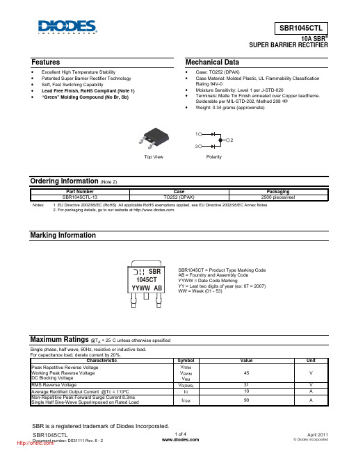
10A SBRSUPER BARRIER RECTIFIERFeatures• Excellent High Temperature Stability• Patented Super Barrier Rectifier Technology • Soft, Fast Switching Capability• Lead Free Finish, RoHS Compliant (Note 1) •“Green” Molding Compound (No Br, Sb)Mechanical Data• Case: TO252 (DPAK)• Case Material: Molded Plastic, UL Flammability Classification Rating 94V-0• Moisture Sensitivity: Level 1 per J-STD-020• Terminals: Matte Tin Finish annealed over Copper leadframe.Solderable per MIL-STD-202, Method 208 •Weight: 0.34 grams (approximate)Ordering Information (Note 2)Part Number CasePackaging SBR1045CTL-13TO252 (DPAK) 2500 pieces/reelNotes:1. EU Directive 2002/95/EC (RoHS). All applicable RoHS exemptions applied, see EU Directive 2002/95/EC Annex Notes2. For packaging details, go to our website at .Marking InformationMaximum Ratings @T A = 25°C unless otherwise specifiedSingle phase, half wave, 60Hz, resistive or inductive load. For capacitance load, derate current by 20%.Characteristic Symbol ValueUnitPeak Repetitive Reverse VoltageWorking Peak Reverse Voltage DC Blocking Voltage V RRM VRWM V RM 45 V RMS Reverse Voltage V R(RMS)31 V Average Rectified Output Current @T C = 110ºC I O10 A Non-Repetitive Peak Forward Surge Current 8.3msSingle Half Sine-Wave Superimposed on Rated Load I FSM90 A Top ViewPolaritySBR1045CT = Product Type Marking Code AB = Foundry and Assembly Code YYWW = Date Code MarkingYY = Last two digits of year (ex: 07 = 2007) WW = Week (01 - 53)YYWW AB1045CT SBRThermal CharacteristicsCharacteristic Symbol Value UnitMaximum Thermal Resistance (per leg) (Note 3) R θJA47 ºC/W Operating and Storage Temperature Range T J , T STG-65 to +150 ºCElectrical Characteristics @T A = 25°C unless otherwise specifiedCharacteristic Symbol Min Typ Max Unit TestConditionReverse Breakdown Voltage (Note 4) V (BR)R 45 - - V I R = 0.5mAForward Voltage Drop (Per Leg) V F- - - 0.5 0.550.53 V I F = 5A, T J = 25ºC I F = 5A, T J = 85ºCLeakage Current (Note 4) I R- - 13 0.5100 mA V R = 45V, T J = 25ºC V R = 45V, T J = 125ºCNotes: 3. Device mounted on polymide substrate 2” x 2”, 2oz. Copper, 1 x MRP double-sided, PC boards.4. Short duration pulse test used to minimize self-heating effect.Fig. 1 Forward Power DissipationI , AVERAGE FORWARD CURRENT (A)F(AV)P , P O W E R D I S S I P A T I O N (W )D Fig. 2 Typical Forward CharacteristicsV , INSTANTANEOUS FORWARD VOLTAGE (V)F I , I N S T A N T A N E O U S F O R W A R D C U R R E N T (A )FFig. 3 Typical Reverse Characteristics V , INSTANTANEOUS REVERSE VOLTAGE (V)R I , I N S T A N T A N E O U S R E V E R S E C U R R E N T (u A )RFig. 4 Total Capacitance vs. Reverse VoltageV , DC REVERSE VOLTAGE (V)R C , T O T A L C A P A C I T A N C E (p F )TFig. 5 Forward Current Derating CurveT , AMBIENT TEMPERATURE (°C)A I , A V E R A G E F O R W A R D C U R R E N T (A )F (A V )Fig. 6 Operating T emperature DeratingV , DC REVERSE VOLTAGE (V)R T , D E R A T E D A M B I E N T T E M P E R A T U R E (°C )APackage Outline DimensionsTO252Dim Min Max Typ A 2.19 2.39 2.29A10.00 0.13 0.08A20.97 1.17 1.07b 0.64 0.880.783b2 0.76 1.14 0.95b3 5.21 5.46 5.33c2 0.45 0.58 0.531D 6.00 6.20 6.10D1 5.21 − − e − − 2.286E 6.45 6.70 6.58E1 4.32−− H 9.40 10.41 9.91L 1.40 1.78 1.59L3 0.88 1.27 1.08L4 0.64 1.02 0.83a 0° 10° − All Dimensions in mmSuggested Pad LayoutIMPORTANT NOTICEDIODES INCORPORATED MAKES NO WARRANTY OF ANY KIND, EXPRESS OR IMPLIED, WITH REGARDS TO THIS DOCUMENT, INCLUDING, BUT NOT LIMITED TO, THE IMPLIED WARRANTIES OF MERCHANTABILITY AND FITNESS FOR A PARTICULAR PURPOSE (AND THEIR EQUIVALENTS UNDER THE LAWS OF ANY JURISDICTION).Diodes Incorporated and its subsidiaries reserve the right to make modifications, enhancements, improvements, corrections or other changes without further notice to this document and any product described herein. Diodes Incorporated does not assume any liability arising out of the application or use of this document or any product described herein; neither does Diodes Incorporated convey any license under its patent or trademark rights, nor the rights of others. Any Customer or user of this document or products described herein in such applications shall assume all risks of such use and will agree to hold Diodes Incorporated and all the companies whose products are represented on Diodes Incorporated website, harmless against all damages.Diodes Incorporated does not warrant or accept any liability whatsoever in respect of any products purchased through unauthorized sales channel. Should Customers purchase or use Diodes Incorporated products for any unintended or unauthorized application, Customers shall indemnify and hold Diodes Incorporated and its representatives harmless against all claims, damages, expenses, and attorney fees arising out of, directly or indirectly, any claim of personal injury or death associated with such unintended or unauthorized application.Products described herein may be covered by one or more United States, international or foreign patents pending. Product names and markings noted herein may also be covered by one or more United States, international or foreign trademarks.LIFE SUPPORTDiodes Incorporated products are specifically not authorized for use as critical components in life support devices or systems without the express written approval of the Chief Executive Officer of Diodes Incorporated. As used herein:A. Life support devices or systems are devices or systems which: 1. are intended to implant into the body, or2. support or sustain life and whose failure to perform when properly used in accordance with instructions for use provided in thelabeling can be reasonably expected to result in significant injury to the user.B. A critical component is any component in a life support device or system whose failure to perform can be reasonably expected to cause the failure of the life support device or to affect its safety or effectiveness.Customers represent that they have all necessary expertise in the safety and regulatory ramifications of their life support devices or systems, and acknowledge and agree that they are solely responsible for all legal, regulatory and safety-related requirements concerning their products and any use of Diodes Incorporated products in such safety-critical, life support devices or systems, notwithstanding any devices- or systems-related information or support that may be provided by Diodes Incorporated. Further, Customers must fully indemnify Diodes Incorporated and its representatives against any damages arising out of the use of Diodes Incorporated products in such safety-critical, life support devices or systems.Copyright © 2011, Diodes IncorporatedDimensionsValue (in mm)Z 11.6 X1 1.5 X2 7.0 Y1 2.5 Y2 7.0 C 6.9 E1 2.3X2CZX1Y1E1Y2分销商库存信息: DIODESSBR1045CTL-13。
C35说明书

1‐+ 2+
電壓脈衝/電流/連續電壓 電流/連續電壓/電壓
補助輸出
16 + 17 ‐
電流或電壓
DI
4 18
3 2
19 20
1
21
COM
RSP/DI
RSP mA/V
‐+ 1189
DI 2 20
1 21
COM
通訊
DA 22
DB 23
SG 24
數字輸入
RSP輸入 數字輸入
RS-485
● 輸入輸出間隔離 實線圍住的部分與其它隔離。
請勿分解本機,否則可能會觸電及產生故障。
■ 外形尺寸
● C3p out
man rsp ev1 ev2 ev3 ot1 ot2
mode para
display enter
96
65 安裝件(附屬品)
108
(單位:mm)
端子螺絲M3
1
96
● C36
96
man
pv
rsp
ev1
ev2
■ 安裝方法
・安裝角度從水平位置向後仰10度以內﹑向前倾10度以內。 ・儀表盤安裝型(C15MT)的場合,請使用板厚在9mm以下的鋼板。
警告
本機在通電前,請務必確認接線是否正確。 接線錯誤會引起故障或危險災害。
本機的接線或安裝、拆卸時,請務必在切斷電源的情況下進行。 否則可能會觸電、產生故障。
請勿觸摸電源端子等受電體。 否則可能會觸電。
:用於數値的増減、位移動。 :顯示的切換。 :設定的變更開始及確定變更中的數値。 :使用與智能編程軟件包同包裝的専用纜線與計算機連
接。
PV量程表
C01 傳感器 設定値 類型
台达变频器使用说明书

RA5 RC5
5kohm 2
AVI
RA6
模擬指令
RC6Βιβλιοθήκη 6←1RS-485 串列通信
1 4~20mA
0~10V/5V(47kohm)
4~20mA 模擬信號共同端
ACi1 (250ohm) ACi2 (250ohm)
ACM
RA7 RC7 RA8 RC8
Relay B.D.
*1~4均為選購品
3-1
VFD-F 系列
外型尺寸
VFD055F43A VFD075F43A
150.0 [5.91] 135.0 [5.32]
R2.75[R0.11]
191.7 [7.55]
244.3 [9.63] 272.1 [10.72]
28.0[ 1.10](2X)
34.0[ 1.34](2X)
UNIT : mm(inch)
2-2
8.3 [0.33]
高壓十分危險,請勿觸摸內部電路及零組件。 3. 絕對不可以自行改裝交流電機驅動器內部的零件或線路。 4. 絕不可將交流電機驅動器輸出端子 U/T1、V/T2、W/T3 連接至 AC 電源。
5. 交流電機驅動器端子 務必正確的接地。460V 系列特種接地。
警告!
1. 請勿對驅動器內部的零組件進行耐壓測試,因驅動器所使用的半導體易受高壓擊穿而損壞。 2. 驅動器的電路板有 cmos IC 極易受靜電的破壞,故在未做好防靜電措施前請勿用手觸摸電路
384.0 [15.12] 403.8 [15.90]
28.0[ 1.10] 13.0 [0.51]
42.0[ 1.65](2X)
10.0 [0.39]
2-4
VFD370F43A VFD450F43A VFD550F43A
BFG425W,115;中文规格书,Datasheet资料
MAX. 10 4.5 30 135 120
UNIT V V mA mW fF GHz dB dB
IC = 25 mA; VCE = 2 V; f = 2 GHz; Tamb = 25 C IC = 25 mA; VCE = 2 V; f = 2 GHz; Tamb = 25 C IC = 2 mA; VCE = 2 V; f = 2 GHz; S = opt CAUTION
1. Gmax is the maximum power gain, if K > 1. If K < 1 then Gmax = MSG; see Figs 6, 7 and 8. 2. ZS is optimized for noise; ZL is optimized for gain.
2010 Sep 15
MIN. 10 4.5 1 50
TYP. 80 300 575 95 25 20 17 0.8 1.2 12 22
MAX. 15 120
UNIT V V V nA fF fF fF GHz dB dB dB dB dBm dBm
Fig.6
Maximum stable gain as a function of collector current; typical values.
2010 Sep 15
5
/
NXP Semiconductors
Product specification
15
10 10 5
0 1 10 IC (mA)
102
0 0 10 20 30 IC (mA) 40
VCE = 2 V; f = 2 GHz; Tamb = 25 C.
Infoprint 250 導入と計画の手引き 第 7 章ホスト
SUBNETMASK
255.255.255.128
Type of service...............: TOS
*NORMAL
Maximum transmission unit.....: MTU
*LIND
Autostart.....................:
AUTOSTART
*YES
: xx.xxx.xxx.xxx
: xx.xxx.xxx.xxx
*
(
)
IEEE802.3
60 1500
: xxxx
48 Infoprint 250
31. AS/400
IP
MTU
1
1
IPDS TCP
CRTPSFCFG (V3R2)
WRKAFP2 (V3R1 & V3R6)
RMTLOCNAME RMTSYS
MODEL
0
Advanced function printing............:
AFP
*YES
AFP attachment........................:
AFPATTACH
*APPC
Online at IPL.........................:
ONLINE
FORMFEED
*CONT
Separator drawer......................:
SEPDRAWER
*FILE
Separator program.....................:
SEPPGM
*NONE
Library.............................:
欧瑞变频器说明书

3.2.2
输入输出端子………………………………………………………………..…….13
四、 操作与显示……………………………………………………………………………………..16
4.1 键盘控制器………………………………………………………………………...………16
4.1.1
操作面板说明……………………………………………………………..……….16
制动方式 直流制动+优化能耗制动
点动
点动范围:0.00~400.0Hz
操作功能
频率设定
数字频率设定,键盘“▲/▼”键调节, “UP”、“DOWN”端子调节 外部模拟信号(0~10V,0~3A)设定 模拟量通道复合运算设定
多段速调速
起/停控制 键盘控制、端子控制
输入缺相,输入欠压,过压,过流,过热,电流检测故障,外部设备故障,用户密码错 保护功能
5.6.1
定时控制…………………………………………………………………………….33
5.6.2
可设定保护-欠压保护、过载保护……………………………………………….33
5.6.3
故障记录…………………………………………………………………………….34
5.7 模拟量参数………………………………………………………………………………….34
其它功能设置使用方法参考f408f410tatbtcout24vcmop1op2op3an1an2i1i110vgndi2i2fmag15安装与配线续表35控制端子功能简介类别端子名称出厂功能功能说明规格i1外部注塑机流量信号输出电流输入端子i1外接电流输入输出外部注塑机流量信号输入03ai2外部注塑机压力信号输出电流输入端子i2外接电流输入输出外部注塑机压力信号输入03aag信号地与fm端子对应备注
卡乐CPP电子控制器中文手册

+050000765 - 1.2 - 24.03.2009
4
2.3 电气规格
电源(控制器带手操器) 绝缘等级 端子排 内置电池的时钟
中文
230 Vac, +10...-15% 适用于CPPA******; 24 Vac +10 to -15% 50/60 Hz, 28 to 36 Vdc +10 to -20% 适用于CPPB****** 最大输入功率: 25 VA 双重绝缘
• 插拔式公制/阴制接头,最大电压 250 Vac;
线缆横截面积: 最小 0.5 mm2 - 最大 2.5 mm2
• 快速接头 • 固定螺接头
仅适用于 CPP****B**/CPP****D** 表. 2.a
2.4 开关量输入
型号: 电压-无源触点
主板类型 小型 中型
数量 7 10
注意:将传感器和开关量输入信号线与带电感负载的线缆和 电源线尽量分离,以避免电磁干扰。
2.5 模拟量输出
类型 最大数量 分辨率 最大负载 精确度
0 to 10 Vdc 小型和中型的主板分别为3个和4个 8位 2 kΩ (5 mA) 满量程±0.3 % 满量程±5 %, 最大负载(5 mA)
表. 2.b
5
+050000765 - 1.2 - 24.03.2009
中文
2.6 模拟量输入
模拟量转换 最大数量 type B1, B2, B3, B4, B8, B9
B5, B10
B6, B7, B11, B12
输入的时间常数 输入的精度 测量回路的分类 (CEI EN 61010-1)
10 位模/数转换 小型的7个,中型的12个 低温NTC型:在25°C时为10 kΩ,± 0.1%,-50~90 °C; 高温NTC型:在25°C时为50 kΩ,0~150 °C; 0~1 Vdc输入; 低温NTC型:在25°C时为10 kΩ, -50~90 °C; 高温NTC型:在25°C时为50 kΩ,0~150 °C; 0~1 Vdc输入; 4~20 mA输入; 低温NTC型:在25°C时为10 kΩ, -50~90 °C; 高温NTC型:在25°C时为50 kΩ,0~150 °C; 0~1 Vdc输入 公制比例式压力传感器(0~5 V) 0.5 秒 满量程±0.3 % I类
CWF1B104H3950;CWF1B103H3380;CWF1B103G3380;CWF1B104F3950;CWF1B103F3380;中文规格书,Datasheet资料

CWFCWF Precision NTC Thermistor Probes for Temperature MeasurementThe CWF series NTC Thermistors are supplied in 5 basic styles of enclosures designed to facilitate installation in a wide variety of applications. PVC leads are applied to a precision, high-reliability NTC thermistor, insulated with heat conductive water resistant materials and potted into any of a wide variety of probe bodies.CWF thermistors are also available with custom housings or custom lead lengths for remote sensing and temperature control in difficult conditions.Also see the Cantherm Thermistor Probe Brochure for additional models.CWFCWF1 (Ethoxyline dipped)Characteristics: Moisture resistant, good insulation, high reliability, small time constant, quick responses.Available Wire Types: AWG 24#, 26#, 28#,30#, PVCApplications: Household air-conditioning, refrigeration and many others.CWF2 (Packaged in aluminum, copper, or stainless steel probe body)Characteristics: High resistance to thermal shock, moisture resistant, strong and secure structure, high dissipation coefficient, the test current can be higher than that of the ethoxyline resin-package.Standard Wire Type: AWG 24#, 26#, 28#,30#, PVCApplications: Refrigeration, air-conditioning, water heaters, drinking fountains, and more.CWF3 (Plastic body)Characteristics: Good dimensional tolerances, good heat resistance and moisture protection, high voltage resistance.Available Wire Types: AWG 24#, 26#, 28#,30#, PVCApplications:Air-conditioning, refrigeration, and more.ABApplications• Heating, ventilation & air conditioning• Temperature regulation and measurement • Automotive electronics • Water heaters• Household appliances such as refrigerators, water coolers, dishwashers and many othersCharacteristics• Wide variety of installation fixtures and probes are available to suit your needs.• Small size and fast response (temperature coefficient of resistance can reach- (2~5%/°C)• Long-term stability and reliability (yearly drift of ≤1%)• Excellent tolerance and interchangeability (the accuracy of R and B value can be ±1%)• Double layer packaging provides excellent insulation and high strength and impact resistance.• Dissipation constant type 1 package ≥2.0mW/°C, type 2 package ≥4.0mW/°C • Time constant of ≤15S to 70SCWF4 (Sheet metal attachment fixtures)Characteristics: Wide variety of fixtures, suitable for most applications.Applications:Fan control, industrial temperature controllers, and more.CWF5 (Custom probes)Characteristics: Small time constant, fast response, flexible and secure.Applications: Water heaters, electronic thermometers, and more.* Also refer to the Cantherm Custom NTC Thermistor Probe Brochure .4A4B4D4C8415 Mountain Sights Avenue • Montreal (Quebec), H4P 2B8, CanadaTel: (514) 739-3274 • 1-800-561-7207 • Fax: (514) 739-2902 • E-mail: sales@NTC Temp sensor Package Option1- Dipped ethoxyline resin (ex. 1S1)2- Aluminum,copper, or stainless steel housing (ex. 2S1) 3- Plastic body (ex. 3AS1)4- Sheet metal attachment fixtures (ex. 4B) 5- Special probes (ex. 5B)The Rated Resistance at 25ºCExample:103 10×103 10000 =10K The Precision Symbol of Rated Resistance F ±1 G ±2 H ±3 J ±5 B value 25/50B value example: 3380KCWF – 103 J 3380分销商库存信息:CANTHERMCWF1B104H3950CWF1B103H3380CWF1B103G3380 CWF1B104F3950CWF1B103F3380CWF4B103G3380 CWF3AA503G3950CWF3AA103G3380CWF1B104J3950 CWF1B104G3950CWF1B103J3380CWF3AA153F3470 CWF3AA202F3470CWF3AA222F3470CWF3AA223F3470 CWF3AA224F4150CWF3AA272F3100CWF3AA332F3470 CWF3AA333F3470CWF3AA472F3470CWF3AA473F3950 CWF3AA474F4300CWF3AA683F3950CWF4B153F3470 CWF4B202F3470CWF4B222F3470CWF4B223F3470 CWF4B224F4150CWF4B272F3100CWF4B332F3470 CWF4B333F3470CWF4B472F3470CWF4B473F3950 CWF4B474F4300CWF4B503F3950CWF4B683F3950 CWF1A103F3380CWF1A104F4150CWF1A503F3950 CWF4B104G4150CWF3AA104G4150。
AM-1045 使用说明书
AM-1045数据采集控制板使用说明书一、概述AM-1045板是PC104总线数据采集板。
该板可以直接插入具备PC104总线兼容计算机的104槽,构成数据采集输入输出系统。
AM-1045板为用户提供了16位16路数据采集输入通道, 模拟量电压输入具有程控放大功能,通过软件可设为1/2/4/8倍,模拟电压信号输入范围-10V~+10V,典型精度优于-0.01%~+0.01%,分辨率16Bit,A/D转换时间为10μS,此板还提供了8bit的数字量输出和8BIT的数字量输入,及2路12位模拟量电压输出。
二、性能和技术指标2.1性能A/D输入分辨率:16Bit16路单端/8路双端输入模拟信号通道A/D转换电路触发工作方式:软件触发A/D转换数据传输工作方式:查询方式D/A输出分辨率:12Bit,2CH2.2技术指标模拟量信号输入部分输入通道数:16路单端输入/8路双端输入输入电压范围:-10V~+10V转换时间:10μS(典型值)精度误差:±4LSB模拟量信号输出部分输出通道数:2路输出电压范围:-5V~+5V(标准);或0~10V, 0V~5V,-10V~+10V(需订货时声明)转换时间:3μS(典型值)精度:优于-0.1%~+0.1%数字量输出部分数字量输出:8位 ;74HC电平输出数字量输入部分数字量输入:8位 ;74HC电平输入三、I/O基地址BASE的设定AM-1045板结构如下:AM-1045PR3 PR4JP1PR5PR6PR7J1插头 PR8PR9JP2JP3PC104插槽本卡的I/O基地址BASE由板上的开关JP3决定,用户可通过设定开关JP3,设定本卡在计算机中所占用的I/O基地址BASE, 其中JP3的1~5对应设定地址线A9~A5,K(n)短接对应地址线设定为0。
如开关JP3出品时设定为300H(见下图一所示),此时开关K的K(3)、K(4)、K(5)) 短接, K(1)、K(2)断开,此时A9和A8=1,而A7;A6;A5均为0,因此基地址BASE为&300H用户可根据所用计算机I/O地址空间设定基地址BASE, 避免I/O地址空间冲突,一般可设在&300H~&33FH图一: JP3A5A6A7A8A9 此时IO基地址BASE=300H四、A/D转换4.1 A/D转换A/D转换由程序启动,方式为在BASE+4端口上任写一数,转换状态可由程序查询读出4.2 A/D转换结束状态标志A/D转换器的状态标志是通过HC245挂到数据线DO上的,读取BASE+0口数据状态,当DO 位=0时A/D正在转换,DO位=1时表示A/D转换结束,此时可以读取A/D转换数据。
gvf-3规格表第二版本

技密AA (工场) GVF-III规格表参数说明第 1 页共 24 页阅 读 说 明GVF-III电梯EVECD微机所用的规格表参数ROM地址的范围为40018-411EC,其中40018-40517为定时器设定区,40720-40899为IO变量设定区;RAM地址为118008—1191DC,其中118008—118507为定时器设定区,118710—1188ef为IO变量设定区。
@1.参数说明中代号说明:“k**”表示其对应数据寄存器的数据是以十进制方式表示,具体数值根据不 同的设定而不同。
“H**”表示其对应数据寄存器的数据是以十六进制方式表示,具体数值根据 不同的设定而不同。
“有功能”是指电梯具有某特定功能时数据寄存器的设定值。
“无功能”是指电梯不设定某特定功能时数据寄存器的设定值。
“------”是指设定数据寄存器参数时不需要考虑电梯是否具有某特定功能。
2.备注说明:“已取消”表示该变量在程序中未使用,该变量在程序中无意义。
“未使用”表示该变量在程序中有使用,但是其功能未体现,属可扩展功能用。
3.计算公式中符号说明:I为曳引比。
D为绳轮直径(mm)。
R为减速比。
N为旋转编码器脉冲数。
4.本规格表说明用于指引GVF-III梯B1000101、B1000102版程序,GVF-III梯其它版本程序仅作参考用。
spechd(0) 40000 ------ ------H0 和数计算开始地址,H40000 spechd(1) 40001 ------ ------H4 和数计算开始地址,H40000 spechd(2) 40002 ------ ------H0 和数计算开始地址,H40000 spechd(3) 40003 ------ ------H0 和数计算开始地址,H40000 spechd(4) 40004 ------ ------H0 和数计算开始地址,H40000 spechd(5) 40005 ------ ------H0 和数计算开始地址,H40000spechd(6) 40006 ------ ------H** 和数计算字节数,规格表和数计算长度,在规格表增加或者减少变量时才会发生变化,具体的长度可从程序的BIN文件中$30006中获取。
格力家用高温型空气能热水器技术服务手册
1 机组控制...................................................................................................8
8 电气安装.................................................................................................19
5安装原理图排气阀水温感温包2排污口截止阀自来水截止阀b过滤器安全止回阀热水输出截止阀c承压水箱截止阀a排水接头b水温感温包1对接进水口出水口排水接头a主机水箱接地线冷水进循环进循环出热水出漏电开关排污口截止阀自来水截止阀常开过滤器安全止回阀热水输出截止阀保温水箱截止阀a手动排气阀b进水口出水口手动排气阀a主机冷水进循环进循环出电辅热电源线自动排气阀水温感温包1对接水温感温包2水箱接地线配电辅热配置安装示意图说明
1.1 主机外形尺寸.......................................................................................................................... 14
1.2 水箱外形及安装尺寸............................................................................................................... 14
华大驱动器说明书-中文
● 防止触电
安全注意事项
危险
· 接线或检测之前,请确认电源处于 OFF 状态。 · 请电气工程人员进行接线作业。 · 接地端子请务必接地。 · 请用干手操作开关,防止电击。 · 电源接通后,请勿触摸端子或打开外罩,否则可能导致电击。
2.1 安装场所................................................................................................................................. 8
2.2 安装方向和空间..................................................................................................................... 8
● 其他
· 绝对不要自行改造伺服驱动器。
ห้องสมุดไป่ตู้
注意
3
SAF
· 目录
第 1 章 型号与规格 .................................................................................................................... 6
第四章 参数 .............................................................................................................................. 28
VRF产品参数表标准2015版

VRF产品参数表标准2015版型号RFUT(D) RFUT(D) RFUT(D) RFUT(D) RFUT(D) RFUT(D) RFUT(D) RFUT(D) RFUT(D) RFUT(D) RFUT(D) RFUT(D) RFUT(D) RFUT(D) RFUT(D) RFUT(D) RFUT(D) RFUT(D) 18MX 22MX 25MX 28MX 32MX 36MX 40MX 45MX 50MX 56MX 63MX 71MX 80MX 90MX 100MX 112MX 125MX 140MX电源(Ph/V/Hz)单相,220V,50Hz名义制冷能力(kW)※1 1.8 2.2 2.5 2.8 3.2 3.6 4 4.5 5 5.6 6.3 7.1 8 9 10 11.2 12.5 14 制冷制冷输入功率(W)57 57 57 57 57 57 89 89 120 120 120 120 120 138×2138×2138×2138×2138×2制冷运行电流(A)0.26 0.26 0.26 0.26 0.26 0.26 0.4 0.4 0.55 0.55 0.55 0.55 0.55 1.25 1.25 1.25 1.25 1.25 名义制热能力(kW)※2 2.3 2.5 2.8 3.2 3.6 4 4.5 5 5.6 6.3 7.1 8 9 10 11 12.5 15 16 制热制热输入功率(W)57 57 57 57 57 57 89 89 120 120 120 120 120 138×2138×2138×2138×2138×2制热运行电流(A)0.26 0.26 0.260.26 0.26 0.26 0.4 0.4 0.55 0.55 0.55 0.55 0.55 1.25 1.25 1.25 1.251.25 辅助电电热能力(kW) 1 1 1 1 1 1 1.8 1.8 1.8 1.8 1.8 1.8 1.8 3.6 3.6 3.6 3.6 3.6 加热辅电电流(A) 4.6 4.6 4.6 4.6 4.6 4.6 8.2 8.2 8.2 8.2 8.2 8.2 8.2 16.4 16.4 16.4 16.4 16.4 低温制热能力(kW)※3 1.6 22.2 2.5 2.83.2 3.6 44.5 55.66.37.1 8 9 10 11.2 12.5 风扇类别及数量离心×1离心×1离心×1离心×1离心×1离心×1离心×2离心×2离心×2离心×2离心×2离心×2离心×2离心×4离心×4离心×4离心×4离心×4电机输出功率(kw)0.018 0.018 0.018 0.018 0.018 0.014 0.032 0.032 0.035 0.035 0.035 0.035 0.035 0.065×20.065×20.065×20.065×20.065×2风机特标准风量(m3/ h) 400 400 400 400 500 500 850 850 1250 1250 1250 1250 1250 1800 1800 1800 1800 1800 性标准静压(Pa)0 0 0 0 0 0 0 0 0 0 0 0 0 0 0 0 0 0 最大静压(Pa)20 20 20 20 20 20 20 20 20 20 20 20 20 20 20 20 20 20室内机外形尺寸:长×宽610×500×2201105×500×2201656×520×220×高(mm)室内机装箱尺寸:长×宽707×548×2801174×549×2941696×523×255×高(mm)尺寸面板外形尺寸:长×宽×------ ------ ------ ------ ------ ------ ------ ------ ------ ------ ------ ------ ------ ------ ------ ------ ------ ------ 高(mm)面板装箱尺寸:长×宽×------ ------ ------ ------ ------ ------ ------ ------ ------ ------ ------ ------ ------ ------ ------ ------ ------ ------ 高(mm)15/17 15/17 15/17 15/17 16/18 16/18室内机净重/毛重(kg)((((((25/27 25/27 28/30 28/30 28/30 28/30 28/30 38/40 40/42 40/42 40/42 40/42重量15.5/17 15.5/17 15.5/17 15.5/17 16.5/18 16.5/18 (26/28) (26/28) (29/31) (29/31) (29/31) (29/31) (29/31) (40/42) (42/44) (42/44) (42/44) (42/44) .5).5).5).5).5).5)面板净重/毛重(kg)------ ------ ------ ------ ------ ------ ------ ------ ------ ------ ------ ------ ------ ------ ------ ------ ------ ------ 节流方式电子膨胀阀线控器YR-E14/YR-E17/YR-E16/YR-E160控制器是否标配否遥控器YR-H005遥控器总成是否标配否气管(mm) φ9.52 φ9.52 φ9.52 φ9.52 φ12.7 φ12.7 φ12.7 φ12.7 φ12.7 φ12.7 φ15.88 φ15.88 φ15.88 φ15.88 φ19.05 φ19.05 φ19.05 φ19.05配管尺液管(mm) φ6.35 φ6.35 φ6.35 φ6.35 φ6.35 φ6.35 φ6.35φ6.35 φ6.35 φ6.35 φ9.52 φ9.52 φ9.52 φ9.52 φ9.52 φ9.52 φ9.52 φ9.52 寸水管(mm) φ24 φ24 φ24 φ24 φ24 φ24 φ24 φ24 φ24 φ24 φ24 φ24 φ24 φ24 φ24 φ24 φ24 φ24冷媒配管连接方式喇叭口喇叭口喇叭口喇叭口喇叭口喇叭口喇叭口喇叭口喇叭口喇叭口喇叭口喇叭口喇叭口喇叭口喇叭口喇叭口喇叭口喇叭口噪音声压级(dB(A))35/32/ 35/32/ 35/32/ 35/32/ 35/32/ 35/32/ 35/32/ 35/32/ 39/37/ 39/37/ 39/37/ 39/37/ 39/37/ 47/45/ 47/45/ 47/45/ 47/45/ 47/45/ 30 30 30 30 30 30 30 30 35 35 35 35 35 43 43 43 43 43※4声功率级(dB(A))------ ------ ------ ------ ------ ------ ------ ------ ------ ------ ------ ------ ------ ------ ------ ------ ------ ------※1 室内温度:27℃DB,19℃WB/室外温度:35℃DB,24℃WB /等效管长:7.5m,高低差:0m ※2室内温度:20℃DB,14.5℃WB/室外温度:7℃DB,6℃WB /等效管长:7.5m,高低差:0m ※3 室内温度:20℃DB,14.5℃WB/室外温度:2℃DB,1℃WB /等效管长:7.5m,高低差:0m ※4 本噪音值是在半消音室内测得的,因受周围噪音及反射声的影响,一般要高于本噪音值编制人:型号RFTS(D)18MX RFTS(D)22MX RFTS(D)25MX RFTS(D)28MX RFTS(D)32MX RFTS(D)36MX RFTS(D)40MX RFTS(D)45MX RFTS(D)50MX RFTS(D)56MX RFTS(D)63MX RFTS(D)71MX 电源(Ph/V/Hz)单相,220V,50Hz名义制冷能力(kW)※1 1.8 2.2 2.5 2.8 3.2 3.6 4 4.5 5 5.6 6.3 7.1制冷制冷输入功率(W)50 50 50 50 56 56 65 65 80 80 117117 制冷运行电流(A)0.23 0.23 0.23 0.23 0.26 0.26 0.3 0.3 0.37 0.37 0.54 0.54 名义制热能力(kW)※2 2.3 2.5 2.8 3.2 3.6 4 4.5 5 5.6 6.3 7.1 8制热制热输入功率(W)50 50 50 50 56 56 65 65 80 80 117 117 制热运行电流(A)0.23 0.23 0.23 0.23 0.26 0.26 0.3 0.3 0.37 0.37 0.54 0.54辅助电电热能力(kW) 1 1 1 1 1 1 1 1 1.8 1.8 1.8 1.8加热辅电电流(A) 4.6 4.6 4.6 4.6 4.6 4.6 4.6 4.6 8.2 8.2 8.2 8.2 低温制热能力(kW)※3 1.6 2 2.2 2.5 2.8 3.2 3.6 4 4.5 5 5.6 6.3 风扇类别及数量离心×2离心×2离心×2离心×2离心×2离心×2离心×2离心×2离心×3离心×3离心×3离心×3电机输出功率(kw)0.014 0.014 0.014 0.014 0.023 0.023 0.051 0.051 0.044 0.044 0.055 0.055风机特标准风量(m3/ h) 480 480 480 480 550 550 600 600 800 800 930 930性标准静压(Pa)0 0 0 0 0 0 0 0 0 0 0 0 最大静压(Pa)30 30 30 30 30 30 30 30 30 30 30 30室内机外形尺寸:长×宽850×420×1851170×420×185×高(mm)室内机装箱尺寸:长×宽1045×540×2701365×540×270×高(mm)尺寸面板外形尺寸:长×宽×------ ------ ------ ------ ------ ------ ------ ------ ------ ------ ------ ------ 高(mm)面板装箱尺寸:长×宽×------ ------ ------ ------ ------ ------ ------ ------ ------ ------ ------ ------ 高(mm)室内机净重/毛重(kg)16.5/21.5 16.5/21.5 16.5/21.516.5/21.5 17.5/22.5 17.5/22.5 18.5/23.5 18.5/23.5 22.2/28.5 22.2/28.5 24/30 24/30重量(17.5/22.5) (17.5/22.5) (17.5/22.5) (17.5/22.5) (18.5/23.5) (18.5/23.5) (19.5/24.5) (19.5/24.5) (23.7/30) (23.7/30) (25.5/31.5) (25.5/31.5) 面板净重/毛重(kg)------ ------ ------ ------ ------ ------ ------ ------ ------ ------ ------ ------ 节流方式电子膨胀阀线控器YR-E14/YR-E17/YR-E16/YR-E160控制器是否标配否遥控器YR-H005遥控器总成是否标配否气管(mm) φ9.52 φ9.52 φ9.52 φ9.52 φ12.7 φ12.7 φ12.7 φ12.7 φ12.7 φ12.7 φ15.88 φ15.88配管尺液管(mm) φ6.35 φ6.35 φ6.35 φ6.35 φ6.35 φ6.35 φ6.35 φ6.35 φ6.35 φ6.35 φ9.52 φ9.52 寸水管(mm) φ25 φ25 φ25 φ25 φ25 φ25 φ25 φ25 φ25 φ25 φ25 φ25冷媒配管连接方式喇叭口喇叭口喇叭口喇叭口喇叭口喇叭口喇叭口喇叭口喇叭口喇叭口喇叭口喇叭口噪音声压级(dB(A))27/24/21 27/24/21 27/24/21 27/24/21 30/28/25 30/28/25 33/30/37 33/30/37 33/30/28 33/30/28 36/33/31 36/33/31 ※4声功率级(dB(A))------ ------ ------ ------ ------ ------ ------ ------ ------ ------ ------ ------※1 室内温度:27℃DB,19℃WB/室外温度:35℃DB,24℃WB /等效管长:7.5m,高低差:0m ※2室内温度:20℃DB,14.5℃WB/室外温度:7℃DB,6℃WB /等效管长:7.5m,高低差:0m ※3 室内温度:20℃DB,14.5℃WB/室外温度:2℃DB,1℃WB /等效管长:7.5m,高低差:0m ※4 本噪音值是在半消音室内测得的,因受周围噪音及反射声的影响,一般要高于本噪音值编制人:型号RFTSA(D) RFTSA(D) RFTSA(D) RFTSA(D) RFTSA(D) RFTSA(D) RFTSA(D) RFTSA(D) RFTSA(D) RFTSA(D) RFTSA(D) RFTSA(D) 18MX 22MX 25MX 28MX 32MX 36MX 40MX 45MX 50MX 56MX 63MX 71MX电源(Ph/V/Hz)单相,220V,50Hz名义制冷能力(kW)※1 1.8 2.2 2.5 2.8 3.2 3.6 4 4.5 5 5.6 6.3 7.1 制冷制冷输入功率(W)50 50 50 50 56 56 65 65 80 80 117 117 制冷运行电流(A)0.23 0.23 0.23 0.23 0.26 0.26 0.3 0.3 0.37 0.37 0.54 0.54 名义制热能力(kW)※2 2.3 2.5 2.8 3.2 3.6 4 4.5 5 5.6 6.3 7.1 8制热制热输入功率(W)50 50 50 50 56 56 65 65 80 80 117 117 制热运行电流(A)0.23 0.23 0.23 0.23 0.26 0.26 0.3 0.3 0.37 0.37 0.54 0.54辅助电电热能力(kW) 1 1 1 1 1 1 1 1 1.8 1.8 1.8 1.8 加热辅电电流(A) 4.6 4.6 4.6 4.6 4.6 4.6 4.6 4.6 8.2 8.2 8.2 8.2 低温制热能力(kW)※3 1.6 2 2.2 2.5 2.8 3.2 3.6 4 4.5 5 5.6 6.3 风扇类别及数量离心×2离心×2离心×2离心×2离心×2离心×2离心×2离心×2离心×3离心×3离心×3离心×3电机输出功率(kw)0.014 0.014 0.014 0.014 0.023 0.023 0.051 0.051 0.044 0.044 0.055 0.055 风机特标准风量(m3/ h) 480 480 480 480 550 550 600 600 800 800 930 930 性标准静压(Pa)0 0 0 0 0 0 0 0 0 0 0 0 最大静压(Pa)30 30 30 30 30 30 30 30 30 30 30 30室内机外形尺寸:长×宽850×420×1851170×420×185×高(mm)室内机装箱尺寸:长×宽1045×540×2701365×540×270×高(mm)尺寸面板外形尺寸:长×宽×------ ------ ------ ------ ------ ------ ------ ------ ------ ------ ------ ------ 高(mm)面板装箱尺寸:长×宽×------ ------ ------ ------ ------ ------ ------ ------ ------ ------ ------ ------ 高(mm)室内机净重/毛重(kg)15.7/20.7 15.7/20.7 15.7/20.7 15.7/20.7 16.7/21.7 16.7/21.7 17.7/22.7 17.7/22.7 21.4/27.4 21.4/27.4 23.2/29.2 23.2/29.2重量(16.7/21.7) (16.7/21.7) (16.7/21.7) (16.7/21.7) (17.7/22.7) (17.7/22.7) (18.7/23.7) (18.7/23.7) (22.9/28.9) (22.9/28.9) (24.7/30.7) (24.7/30.7) 面板净重/毛重(kg)------ ------ ------ ------ ------ ------ ------ ------ ------ ------ ------ ------ 节流方式电子膨胀阀线控器YR-E14/YR-E17/YR-E16/YR-E160控制器是否标配否遥控器YR-H005遥控器总成是否标配否气管(mm) φ9.52 φ9.52 φ9.52 φ9.52 φ12.7 φ12.7 φ12.7 φ12.7 φ12.7 φ12.7 φ15.88 φ15.88配管尺液管(mm) φ6.35 φ6.35 φ6.35 φ6.35 φ6.35 φ6.35 φ6.35 φ6.35 φ6.35 φ6.35 φ9.52 φ9.52 寸水管(mm) φ25 φ25 φ25 φ25 φ25 φ25 φ25 φ25 φ25 φ25 φ25 φ25冷媒配管连接方式喇叭口喇叭口喇叭口喇叭口喇叭口喇叭口喇叭口喇叭口喇叭口喇叭口喇叭口喇叭口噪音声压级(dB(A))27/24/21 27/24/21 27/24/21 27/24/21 30/28/25 30/28/25 33/30/37 33/30/37 33/30/28 33/30/28 36/33/31 36/33/31 ※4声功率级(dB(A))------ ------ ------ ------ ------ ------ ------ ------ ------ ------ ------ ------※1 室内温度:27℃DB,19℃WB/室外温度:35℃DB,24℃WB /等效管长:7.5m,高低差:0m ※2室内温度:20℃DB,14.5℃WB/室外温度:7℃DB,6℃WB /等效管长:7.5m,高低差:0m ※3 室内温度:20℃DB,14.5℃WB/室外温度:2℃DB,1℃WB /等效管长:7.5m,高低差:0m ※4 本噪音值是在半消音室内测得的,因受周围噪音及反射声的影响,一般要高于本噪音值编制人:相当马力2 2.53 3.2 3.64 4.5 5 5.3型号RFUM(D)56MX RFUM(D)71MX RFUM(D)80MX RFUM(D)90MX RFUM(D)100MX RFUM(D)112MX RFUM(D)125MX RFUM(D)140MX RFUM(D)150MX电源(Ph/V/Hz )单相,220V ,50Hz名义制冷能力(kW )※1 5.6 7.1 8 9 10 11.2 12.5 14 15 制冷制冷输入功率(W ) 235 235 235 280 280 280 280 280 280 制冷运行电流(A ) 1.1 1.1 1.1 1.4 1.4 1.4 1.4 1.4 1.4 名义制热能力(kW )※2 6.3 8 9 10 11.2 12.5 15 16 17制热制热输入功率(W ) 235 235 235 280 280 280 280 280 280制热运行电流(A ) 1.1 1.1 1.1 1.4 1.4 1.4 1.4 1.4 1.4辅助电电热能力(kW ) 1.8 1.8 1.8 2.4 2.4 2.4 2.4 2.4 2.4加热辅电电流(A )8.2 8.2 8.2 10.91 10.9110.91 10.91 10.91 10.91 低温制热能力(kW )※35 6 7.1 8 910 11.2 12.5 13风扇类别及数量离心×2 离心×2 离心×2 离心×3 离心×3 离心×3 离心×3 离心×3 离心×3电机输出功率(kw ) 0.088 0.088 0.088 0.14 0.140.14 0.14 0.14 0.14 风机特标准风量(m 3/ h)1200 1200 1200 1900 19001900 2100 2100 2100 性标准静压(Pa ) 50 50 50 50 5050 50 50 50最大静压(Pa )969696969696969696室内机外形尺寸:长×宽×高(mm )990×655×3001418×655×350室内机装箱尺寸:长×宽尺寸×高(mm )1180×743×3401610×765×400面板外形尺寸:长×宽×高(mm )------ ------ ------ ------ ------ ------ ------ ------ ------面板装箱尺寸:长×宽×高(mm )------ ------ ------ ------ ------------ ------ ------ ------ 重量室内机净重/毛重(kg ) 40/46 40/46 40/46 61/68 61/6861/68 61/68 61/68 61/68 面板净重/毛重(kg ) ------------------------------------------------------节流方式电子膨胀阀线控器YR-E14/YR-E17/YR-E16/YR-E160控制器是否标配否遥控器YR-H005遥控器总成是否标配否气管(mm)¢12.7 ¢15.88 ¢15.88 ¢15.88 ¢15.88 ¢15.88 ¢15.88 ¢15.88 ¢15.88 配管尺液管(mm)¢6.35 ¢9.52 ¢9.52 ¢9.52 ¢9.52¢9.52 ¢9.52 ¢9.52 ¢9.52 寸水管(mm)¢32 ¢32 ¢32 ¢32 ¢32¢32 ¢32 ¢32 ¢32冷媒配管连接方式喇叭口喇叭口喇叭口喇叭口喇叭口喇叭口喇叭口喇叭口喇叭口噪音※4声压级(dB(A))43/37/35 43/37/35 43/37/35 43/37/35 43/37/3543/37/35 44/40/36 44/40/36 44/40/36 声功率级(dB(A))------------------------------------------------------※1 室内温度:27℃DB ,19℃WB/室外温度:35℃DB ,24℃WB /等效管长:7.5m ,高低差:0m ※2 室内温度:20℃DB ,14.5℃WB/室外温度:7℃DB ,6℃WB /等效管长:7.5m ,高低差:0m ※3 室内温度:20℃DB ,14.5℃WB/室外温度:2℃DB ,1℃WB /等效管长:7.5m ,高低差:0m ※4 本噪音值是在半消音室内测得的,因受周围噪音及反射声的影响,一般要高于本噪音值编制人:高静压风管机RFU (D )-A 系列参数表相当马力2.02.53.04.05.08.010.0 型号RFU(D)56MX-A RFU(D)71MX-A RFU(D)80MX-ARFU(D)90MX-A RFU(D)112MX-A RFU(D)140MX-ARFU226MX-ARFU280MX-A电源(Ph/V/Hz )单相,220V ,50Hz单相,220V ,50Hz名义制冷能力(kW )※15.67.18.0 9.0 11.2 14.022.628.0 制冷制冷输入功率(W )450450 450560 560 560600 600制冷运行电流(A )2.05 2.052.052.55 2.55 2.553.0名义制热能力(kW )※26.38.09.010.0 12.5 16.025.0 31.0制热制热输入功率(W )450450450560 560 560600600制热运行电流(A )2.052.052.052.55 2.552.553.0 3.0辅助电电热能力(kW ) 2.6 2.6 2.6 3.8 3.8 3.8 ------ ------ 加热辅电电流(A )11.9 11.9 11.9 17.317.3 17.3 ------ ------低温制热能力(kW )※35.07.18.0 10.012.5 21.525.0风扇类别及数量离心×2离心×2离心×2 离心×2离心×2离心×2离心×4 离心×4电机输出功率(kw )0.26 0.26 0.26 0.2650.265 0.265 0.238×2 0.238×2 风机特标准风量(m 3 / h)15001500 1500156016002100 40504050 性标准静压(Pa )100 100100 100100 100100 100最大静压(Pa ) 196196 196196196 196196室内机外形尺寸:长×宽×高(mm )975×906×360 1355×876×3601725×876×360室内机装箱尺寸:长×宽尺寸×高(mm )1050×945×405 1386×966×4181830×985×490面板外形尺寸:长×宽×------------------------------------------------高(mm )面板装箱尺寸:长×宽×------------------------------------------高(mm )重量室内机净重/毛重(kg )48/5862/77120/140面板净重/毛重(kg )------------------节流方式电子膨胀阀线控器YR-E14/YR-E17/YR-E16/YR-E160 控制器是否标配否遥控器YR-H005遥控器总成是否标配否气管(mm)¢12.7¢15.88¢15.88¢15.88 ¢15.88¢15.88¢25.4¢25.4 配管尺液管(mm)¢9.52¢9.52 ¢9.52¢9.52¢9.52¢9.52 ¢9.52水管(mm) ¢36 ¢36 ¢36 ¢36 ¢36 ¢36 ¢36 ¢36寸冷媒配管连接方式喇叭口喇叭口喇叭口喇叭口喇叭口喇叭口液管喇叭口/气管液管喇叭口/气管焊接焊接噪音声压级(dB(A))42/40 42/40 42/40 45/4045/40 45/40 54/49 54/49 ※4声功率级(dB(A))------------------------------------------------※1 室内温度:27℃DB ,19℃WB/室外温度:35℃DB ,24℃WB /等效管长:7.5m ,高低差:0m ※2 室内温度:20℃DB ,14.5℃WB/室外温度:7℃DB ,6℃WB /等效管长:7.5m ,高低差:0m ※3 室内温度:20℃DB ,14.5℃WB/室外温度:2℃DB ,1℃WB /等效管长:7.5m ,高低差:0m ※4 本噪音值是在半消音室内测得的,因受周围噪音及反射声的影响,一般要高于本噪音值编制人:。
朔风抗冻壁挂瓶ountain产品说明书
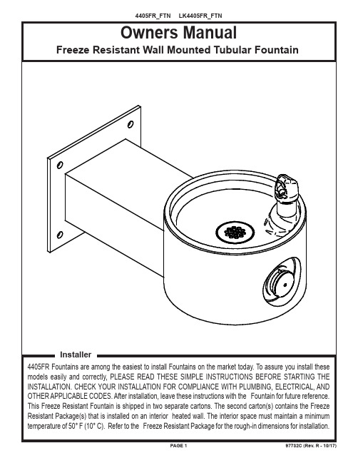
PAGE 197732C (Rev. R - 10/17)PAGE 297732C (Rev.R - 10/17)The freeze resistant package must be mounted on an interior wall in a heated area. The room temperature of theinterior heated area must be 50° F (10° C) or higher. The freeze resistant package may be surface or recessed mounted. If recess mounted the surface of the cover must be flush with the interior wall surface. The package is furnished with screws for mounting the cover to the box. If the box is recess mounted, do not fasten the top and bottom of the cover to the box. Use the holes on the front only.1. Assemble the operating cable to the fountain bracket. (Fountain should be mounted to exterior wall.) Theadjustment nuts should be in the middle of threaded area on the operating cable. See Figure 5. Create a loop in the cable and thread the free end of the cable through the wall into the freeze resistant box. 2. Connect free end of operating cable to the valve-operating bracket in the freeze resistant box.3. Remove cable free play by adjusting the jam nuts on the ends of the operating cable. See Figure 6.4. Connect water line from fountain bubbler into freeze resistant box. The connection to the box uses a quickconnect water fitting. Position the water line, in the fountain, to drain back into interior mounted box. Any water left standing, in the exterior line, can freeze . See Fig. 8.To insert tubing, push tube straight into fitting until it reaches a positive stop. T o remove tubing from the fittings, relieve water pressure, push in on dark gray collar while pulling out on the tubing. See Figure 11.5. Connect drain and water supply lines to the freeze resistant fountain. Refer to Figure 1 for component positions. Inline strainer must be used on the inlet water line. See Fig. 10.Start-up1. Turn on building water supply and check all connections for leaks. Repair as required.2. Stream height is factory set at 35 PSI. If stream height needs to be changed adjust the regulator in the freezeresistant package. Clockwise adjustment raises stream height, counter clockwise adjustment will lower stream.3. Adjust operating cable as required. Cable system should have a minimal amount of free play to allow for propervalve operation. If the system is too tight the valve will stay in the on position creating constant water flow. Too much free play will result in non-operation of the valve with the push-buttons.4. Note: Water from the drain back tube in the freeze resistant package, will continue to run while the valve isactuated.5. After cable system is adjusted properly stuff flexible insulation into any openings between the outside wall and theinterior box.6. Recheck all connections. If all connections are leak free replace cover(s) on the freeze resistant box(es) andfountain(s).INSTALLATION INSTRUCTIONSIMPORTANTALL SERVICE TO BE PERFORMED BY AN AUTHORIZED SERVICE PERSONIMPORTANT! INSTALLER PLEASE NOTE.THE GROUNDING OF ELECTRICAL EQUIPMENT SUCH AS TELEPHONE, COMPUTERS, ETC. TO WATER LINES IS A COMMON PROCEDURE. THIS GROUNDING MAY BE IN THE BUILDING OR MAY OCCUR AWAY FROM THE BUILDING. THIS GROUNDING CAN CAUSE ELECTRICAL FEEDBACK INTO A FOUNTAIN, CREATING AN ELECTROLYSIS WHICH CAUSES A METALLIC TASTE OR AN INCREASE IN THE METAL CONTENT OF THE WATER. THIS CONDITION IS AVOIDABLE BY USING THE PROPER MATERIALS AS INDICATED. ANY DRAIN FITTINGS PROVIDED BY THE INSTALLER SHOULD BE MADE OF PLASTIC TO ELECTRICALLY ISOLATE THE FOUNTAIN FROM THE BUILDING PLUMBING SYSTEM.PAGE 397732C (Rev. R - 10/17)97732C (Rev.R - 10/17)PAGE 4FIG. 5See Fig.5 FIG. 8PAGE 697732C (Rev.R - 10/17)PRINTED IN U.S.A.Halsey Taylor – Elkay – FOR PARTS CONTACT YOUR LOCAL DISTRIBUTOR OR CALL TECHNICAL SERVICES AT 1.800.834.48162222 CAMDEN COURT, OAK BROOK, ILLINOIS 60523A SIMPLY PUSH IN TUBE TO ATTACH TUBE IS SECUREDIN POSITION PUSH IN COLLETTO RELEASE TUBE OPERATION OF QUICK CONNECT FITTINGSPUSHING TUBE IN BEFORE PULLING IT OUT HELPS TO RELEASE TUBE OPERATION OF QUICK CONNECT FITTINGS SIMPLY PUSH IN TUBE TO ATTACHTUBE IS SECURED IN POSITIONPUSH IN COLLET TO RELEASE TUBEPUSHING TUBE IN BEFORE PULLING IT OUT HELPS TORELEASE TUBEA B CNOTE: WATER FLOWDIRECTIONSERVICE STOP (NOT FURNISHED)592136, 6a, 6b15713, 20121162314112218172441981082FIG. 12FIG. 13FIG. 10FIG. 11Vandal-Resistant BubblerBASIN5。
STMicroelectronics STPS1045SFY 45V Power Schottky
STPS1045SFYFeatures•AEC-Q101 qualified •Low capacitance•Negligible switching losses •Avalanche capability specified•175 °C maximum junction temperature •V RRM guaranteed from -40 °C to 175 °C •Wettable flanks for automatic visual inspection •PPAP capable•ECOPACK ®2 compliant componentApplication•DC/DC converters•Reverse polarity protection •Freewheeling diodes •Switching diodesDescriptionThe STPS1045SFY power Schottky rectifier has been designed for automotive applications.Packaged in PSMC (TO-277A), this device provides a very low V F in a compact package which can withstand high operating junction temperature.Automotive 45 V power Schottky rectifierSTPS1045SFYDatasheetSTPS1045SFYCharacteristics 1CharacteristicsTable 1. Absolute ratings (limiting values at 25 °C, unless otherwise specified with 2 anode terminalsshort-circuited)1.(dP tot/dT j) < (1/R th(j-a)) condition to avoid thermal runaway for a diode on its own heatsink.Table 2. Thermal resistance parametersFor more information, please refer to the following application note:•AN5088: Rectifiers thermal management, handling and mounting recommendationsTable 3. Static electrical characteristics (anode terminals short-circuited)1.Pulse test: t p = 5 ms, δ < 2%2.Pulse test: t p = 380 µs, δ < 2%To evaluate the conduction losses, use the following equation:P = 0.35 x I F(AV) + 0.022 x I F2(RMS)For more information, please refer to the following application notes related to the power losses:•AN604: Calculation of conduction losses in a power rectifier•AN4021: Calculation of reverse losses in a power diodeSTPS1045SFYCharacteristics (curves) 1.1Characteristics (curves)Figure 7. Thermal resistance junction to ambient versus copper surface under tab (typical values, epoxyprinted board FR4, e Cu = 35 µm) (PSMC (TO-277A))020406080100120012345678910STPS1045SFYCharacteristics (curves)2Package informationIn order to meet environmental requirements, ST offers these devices in different grades of ECOPACK ®packages, depending on their level of environmental compliance. ECOPACK ® specifications, grade definitions and product status are available at: . ECOPACK ® is an ST trademark.2.1PSMC (TO-277A) package information•Epoxy meets UL94,V0•Cooling method : by conduction (C)Figure 8.PSMC (TO-277A) package outlineTable 4. PSMC (TO-277A) package mechanical dataSTPS1045SFYPackage informationFigure 9.PSMC (TO-277A) package footprint in mm (in inches)STPS1045SFYPSMC (TO-277A) package informationFigure 10.PSMC (TO-277A) markingFigure 11.Package orientation in reelFigure 12.Tape and reel orientationFigure 13. 13'' reel dimension valuesFigure 14. Inner box dimension valuesSTPS1045SFYPSMC (TO-277A) package informationFigure 15.Tape outlineTable 5. Tape dimension valuesSTPS1045SFYPSMC (TO-277A) package informationSTPS1045SFYOrdering information 3Ordering informationTable 6. Ordering informationRevision historyTable 7. Document revision historyIMPORTANT NOTICE – PLEASE READ CAREFULLYSTMicroelectronics NV and its subsidiaries (“ST”) reserve the right to make changes, corrections, enhancements, modifications, and improvements to ST products and/or to this document at any time without notice. Purchasers should obtain the latest relevant information on ST products before placing orders. ST products are sold pursuant to ST’s terms and conditions of sale in place at the time of order acknowledgement.Purchasers are solely responsible for the choice, selection, and use of ST products and ST assumes no liability for application assistance or the design of Purchasers’ products.No license, express or implied, to any intellectual property right is granted by ST herein.Resale of ST products with provisions different from the information set forth herein shall void any warranty granted by ST for such product.ST and the ST logo are trademarks of ST. All other product or service names are the property of their respective owners.Information in this document supersedes and replaces information previously supplied in any prior versions of this document.© 2018 STMicroelectronics – All rights reservedSTPS1045SFY。
球形浓缩器使用说明书
目录一、产品介绍 (3)二、产品特点 (3)三、重要技术参数 (4)四、结构及性能 (4)五、工作原理 (5)六、操作规程 (5)七、设备清洗 (6)八、注意事项 (7)九、设备的维护与保养 (7)十、合格证 (8)十、随机附件 (8)一、产品介绍:球形浓缩装置主要包括夹套式浓缩罐,气滤丝网式捕液器,列管式冷凝器,以及受液贮罐等四部分组成,浓缩罐为夹套结构。
其他所需的真空系统(真空泵、缓冲罐等),料液计量罐,排液泵等由客户自行配套,也可根据客户要求,由我厂代为配套。
球型浓缩罐可用于制药、食品、化工等行业对料液的浓缩、蒸馏及有机溶媒的回收等工艺。
球型浓缩罐由于采用减压浓缩,所以浓缩时间短,且不会破坏热敏性物料的有效成分。
此浓缩设备与物料接触部分均为不锈钢制造(也可以采用其他材质,根据用户需求定制),具有良好的耐腐蚀性能,经久耐用,并符合GMP要求。
1、本设备采用在真空状态下通过夹套外加热。
具有结构先进蒸发温度低、蒸发能力大、浓缩速度快,能满足热敏性物料的低温真空浓缩物含皂多易起泡的物料浓缩。
2、本设备结构紧凑、操作简便、清洗方便、浓缩相对密度可达1.3-1.4(一般中药侵膏),可以浓缩其它蒸发器浓缩的浸膏。
3、本设备与物料接触部分均采用SUS304不锈钢制成,具有优良的耐腐蚀性能,符合药品和食品卫生要求,达到GMP要求。
二、产品特点:1、低温蒸馏,使用物料较广,效率比常压蒸馏高。
2、蒸发效率高,不易结垢。
3、蒸发速度快,浓缩比重大,可达1.2-1.35(一般中药浸膏)。
三、重要技术参数:四、结构及性能①本设备由球形罐、冷凝器器、除沫器、冷凝器、受液罐、循环管等部件组成(以上为标配,可以根据客户的要求进行调整),整套设备采用优质不锈钢材料制成。
②筒体为球形易清洗。
③灌顶设有视灯及视镜便于观察○4、设备易损件:A、人孔法兰密封圈;B、冷凝器上下法兰密封圈;C、视镜玻璃及密封圈。
五、工作原理生蒸汽进入球形罐夹套,将料液加热沸腾,物料中水分或其它有机物体汽化,从而达到汽液分离,蒸发室蒸发出来的蒸汽经除沫器消除泡沫后由冷凝器与冷却器冷却成液体进入贮液桶,最后不凝气体排入大气或真空泵带走。
- 1、下载文档前请自行甄别文档内容的完整性,平台不提供额外的编辑、内容补充、找答案等附加服务。
- 2、"仅部分预览"的文档,不可在线预览部分如存在完整性等问题,可反馈申请退款(可完整预览的文档不适用该条件!)。
- 3、如文档侵犯您的权益,请联系客服反馈,我们会尽快为您处理(人工客服工作时间:9:00-18:30)。
Document Number: 89367For technical questions within your region, please contact one of the following:Trench MOS Barrier Schottky Rectifier for PV Solar Cell Bypass ProtectionUltra Low V F = 0.34 V at I F = 2.5 AVFT1045CBPVishay General SemiconductorFEATURES•Trench MOS Schottky technology•Low forward voltage drop, low power losses •High efficiency operation•Solder bath temperature 275 °C max. 10 s, per JESD 22-B106•Compliant to RoHS Directive 2002/95/EC and in accordance to WEEE 2002/96/EC•Halogen-free according to IEC 61249-2-21 definitionTYPICAL APPLICATIONSFor use in solar cell junction box as a bypass diode for protection, using DC forward current without reverse bias.MECHANICAL DATACase: ITO-220ABMolding compound meets UL 94 V-0 flammability rating Base P/N-M3 - halogen-free, RoHS compliant, and commercial gradeTerminals: Matte tin plated leads, solderable per J-STD-002 and JESD 22-B102M3 suffix meets JESD 201 class 1A whisker test Polarity: As markedMounting Torque: 10 in-lbs maximumNotes(1)With heatsink(2)Meets the requirements of IEC 61215 ed. 2 bypass diode thermal testPRIMARY CHARACTERISTICSI F(AV) 2 x 5.0 A V RRM 45 V I FSM100 A V F at I F = 5.0 A 0.41 V T OP max.150 °CMAXIMUM RATINGS (T A = 25°C unless otherwise noted)PARAMETERSYMBOL VFT1045CBPUNIT Maximum repetitive peak reverse voltage V RRM 45V Maximum average forward rectified current (fig. 1)per device I F(AV) (1)10A per diode5.0Peak forward surge current 8.3 ms single half sine-wave superimposed on rated load per diodeI FSM 100A Isolation voltage from termal to heatsink, t = 1 min V AC 1500V Operating junction and storage temperature range T OP , T STG - 40 to + 150°C Junction temperature in DC forward current without reverse bias, t ≤ 1 hT J (2)≤ 200°C For technical questions within your region, please contact one of the following:Document Number: 89367VFT1045CBPVishay General SemiconductorNotes(1)Pulse test: 300 μs pulse width, 1 % duty cycle (2)Pulse test: Pulse width ≤ 40 msRATINGS AND CHARACTERISTICS CURVES(T A = 25 °C unless otherwise noted)Fig. 1 - Maximum Forward Current Derating Curve Fig. 2 - Forward Power Loss Characteristics Per DiodeELECTRICAL CHARACTERISTICS (T A = 25°C unless otherwise noted)PARAMETER TE S T CONDITION S S YMBOLTYP.MAX.UNITInstantaneous forward voltage per diodeI F = 2.5 AT A = 25 °CV F (1)0.44-V I F = 5.0 A 0.490.58I F = 2.5 A T A = 125 °C 0.34-I F = 5.0 A0.410.50Reverse current per diodeV R = 45 VT A = 25 °C I R (2)-500μA T A = 125 °C515mA THERMAL CHARACTERISTICS (T A = 25°C unless otherwise noted)PARAMETER S YMBOL VFT1045CBP UNIT Typical thermal resistanceper diode R θJC6.5°C/Wper device5.0ORDERING INFORMATION(Example)PACKAGE PREFERRED P/N UNIT WEIGHT (g)PACKAGE CODEBASE QUANTITYDELIVERY MODEITO-220ABVFT1045CBP-M3/4W1.754W50/tubeTubeDocument Number: 89367For technical questions within your region, please contact one of the following:VFT1045CBPVishay General SemiconductorFig. 3 - Typical Instantaneous Forward Characteristics Per Diode Fig. 4 - Typical Reverse Characteristics Per Diode Fig. 5 - Typical Junction Capacitance Per DiodeFig. 6 - Typical Transient Thermal Impedance Per DiodePACKAGE OUTLINE DIMENSIONS in inches (millimeters)Legal Disclaimer Notice VishayDisclaimerALL PRODU CT, PRODU CT SPECIFICATIONS AND DATA ARE SU BJECT TO CHANGE WITHOU T NOTICE TO IMPROVE RELIABILITY, FUNCTION OR DESIGN OR OTHERWISE.Vishay Intertechnology, Inc., its affiliates, agents, and employees, and all persons acting on its or their behalf (collectively,“Vishay”), disclaim any and all liability for any errors, inaccuracies or incompleteness contained in any datasheet or in any other disclosure relating to any product.Vishay makes no warranty, representation or guarantee regarding the suitability of the products for any particular purpose or the continuing production of any product. To the maximum extent permitted by applicable law, Vishay disclaims (i) any and all liability arising out of the application or use of any product, (ii) any and all liability, including without limitation special, consequential or incidental damages, and (iii) any and all implied warranties, including warranties of fitness for particular purpose, non-infringement and merchantability.Statements regarding the suitability of products for certain types of applications are based on Vishay’s knowledge of typical requirements that are often placed on Vishay products in generic applications. Such statements are not binding statements about the suitability of products for a particular application. It is the customer’s responsibility to validate that a particular product with the properties described in the product specification is suitable for use in a particular application. Parameters provided in datasheets and/or specifications may vary in different applications and performance may vary over time. All operating parameters, including typical parameters, must be validated for each customer application by the customer’s technical experts. Product specifications do not expand or otherwise modify Vishay’s terms and conditions of purchase, including but not limited to the warranty expressed therein.Except as expressly indicated in writing, Vishay products are not designed for use in medical, life-saving, or life-sustaining applications or for any other application in which the failure of the Vishay product could result in personal injury or death. Customers using or selling Vishay products not expressly indicated for use in such applications do so at their own risk and agree to fully indemnify and hold Vishay and its distributors harmless from and against any and all claims, liabilities, expenses and damages arising or resulting in connection with such use or sale, including attorneys fees, even if such claim alleges that Vishay or its distributor was negligent regarding the design or manufacture of the part. Please contact authorized Vishay personnel to obtain written terms and conditions regarding products designed for such applications.No license, express or implied, by estoppel or otherwise, to any intellectual property rights is granted by this document or by any conduct of Vishay. Product names and markings noted herein may be trademarks of their respective owners.Material Category PolicyVishay Intertechnology, Inc. hereb y certifies that all its products that are identified as RoHS-Compliant fulfill the definitions and restrictions defined under Directive 2011/65/EU of The European Parliament and of the Council of June 8, 2011 on the restriction of the use of certain hazardous substances in electrical and electronic equipment (EEE) - recast, unless otherwise specified as non-compliant.Please note that some Vishay documentation may still make reference to RoHS Directive 2002/95/EC. We confirm that all the products identified as being compliant to Directive 2002/95/EC conform to Directive 2011/65/EU.Revision: 12-Mar-121Document Number: 91000分销商库存信息:VISHAY-GENERAL-SEMICONDUCTOR VFT1045CBP-M3/4W。