744066151;中文规格书,Datasheet资料
7440650015;中文规格书,Datasheet资料
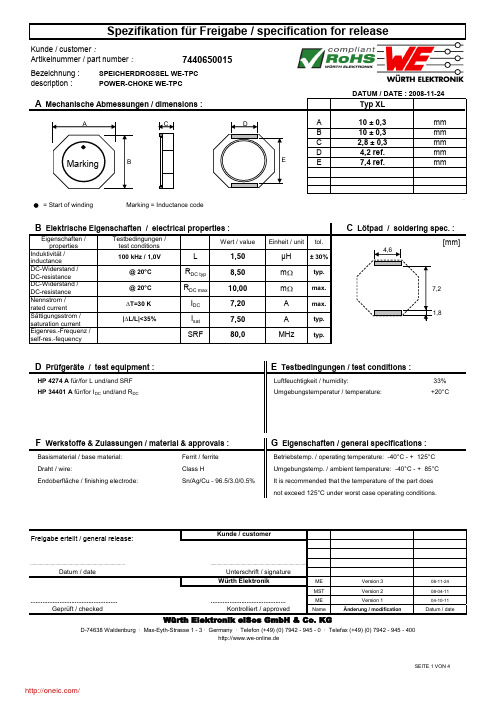
Bezeichnung :description :A mmB mmC mmD mm Emm= Start of winding Marking = Inductance codeEigenschaften / properties Wert / valueEinheit / unittol.Induktivität /inductanceDC-Widerstand /DC-resistance DC-Widerstand /DC-resistance Nennstrom /rated currentSättigungsstrom / saturation current Eigenres.-Frequenz /self-res.-fequency33% Umgebungstemperatur / temperature:+20°CFerrit / ferrite ME 08-11-24MST08-04-11ME 04-10-11NameDatum / dateVersion 2Version 310 ± 0,310 ± 0,32,8 ± 0,34,2 ref.Typ XL7,4 ref...................................................................................Class HSn/Ag/Cu - 96.5/3.0/0.5%Geprüft / checked ...............................................................................................Änderung / modificationVersion 1Freigabe erteilt / general release:Kunde / customerF Werkstoffe & Zulassungen / material & approvals :G Eigenschaften / general specifications :It is recommended that the temperature of the part does not exceed 125°C under worst case operating conditions.Endoberfläche / finishing electrode:Basismaterial / base material:Würth Elektronikhttp://www.we-online.deD-74638 Waldenburg · Max-Eyth-Strasse 1 - 3 · Germany · Telefon (+49) (0) 7942 - 945 - 0 · Telefax (+49) (0) 7942 - 945 - 400Kontrolliert / approvedMHzm |∆L/L|<35%A SRFI sat 7,5080,0@ 20°C Draht / wire:D Prüfgeräte / test equipment :Datum / date..................................................................................Unterschrift / signature E Testbedingungen / test conditions :Betriebstemp. / operating temperature: -40°C - + 125°C Umgebungstemp. / ambient temperature: -40°C - + 85°C Testbedingungen / test conditions 7,20max.m 10,00± 30%A R DC max typ.∆T=30 K typ.DATUM / DATE : 2008-11-24max. C Lötpad / soldering spec. :B Elektrische Eigenschaften / electrical properties :µH Artikelnummer / part number : Luftfeuchtigkeit / humidity:SPEICHERDROSSEL WE-TPC POWER-CHOKE WE-TPCR DC typ 8,50typ.I DC HP 34401 A für/for I DC und/and R DCHP 4274 A für/for L und/and SRF A Mechanische Abmessungen / dimensions :100 kHz / 1,0V @ 20°C L 1,507440650015[mm]7,24,6CABMarkingDE1,8description :ME 08-11-24MST08-04-11ME 04-10-11NameDatum / dateVersion 1Version 2Änderung / modificationD-74638 Waldenburg · Max-Eyth-Strasse 1 - 3 · Germany · Telefon (+49) (0) 7942 - 945 - 0 · Telefax (+49) (0) 7942 - 945 - 400Würth Elektronik eiSos GmbH & Co. KGGeprüft / checked Kontrolliert / approvedWürth Elektronik...................................................................................................................................................................................................................................................................Datum / dateUnterschrift / signature Version 3 http://www.we-online.deH Induktivitätskurve / Inductance curve :Freigabe erteilt / general release:Kunde / customerPOWER-CHOKE WE-TPCDATUM / DATE : 2008-11-240,000,200,400,600,801,001,201,401,600,001,002,003,004,005,006,007,008,009,00L (µH )Current (A)Induktivität vs Strom (typ.) / Inductance vs Current (typ.)description :A 6,6± 0,1mmB 16,0± 0,3mm D 4,00± 0,1mm E 2,00± 0,1mm F 1,75± 0,1mm G 7,00± 0,1mm H 3,40± 0,1mma 330,0± 0,5mmb 20,20± 0,1mmc 13,00± 1,0mmd 100,0± 1,0mmME 08-11-24MST08-04-11ME 04-10-11NameDatum / dateVersion 2Version 3Würth Elektronikmm1,50C Datum / dateUnterschrift / signaturehttp://www.we-online.de...............................................................................................Geprüft / checked Kontrolliert / approvedÄnderung / modificationVersion 1D-74638 Waldenburg · Max-Eyth-Strasse 1 - 3 · Germany · Telefon (+49) (0) 7942 - 945 - 0 · Telefax (+49) (0) 7942 - 945 - 400..................................................................................Würth Elektronik eiSos GmbH & Co. KG..................................................................................POWER-CHOKE WE-TPCI Rollenspezifikation / Tape and reel specification :Gurtspezifikation / Tape specification: DATUM / DATE : 2008-11-24Rollenspezifikation / Reel specification:Freigabe erteilt / general release:Kunde / customer± 0,1HGØ cadbABFEDøCThis electronic component has been designed and developed for usage in general electronic equipment. Before incorporating thi s component into any equipment where higher safety and reliability is especially required or if there is the possibility of direct damage or injury to human body, for example in the range of aerospace, avia tion, nuclear control, submarine, transportation, (automotive control, train control, ship control), transportation signal, disaster prevention, medical, public information network etc, Würth Elektronik eiSos GmbH must be info rmed before the design-in stage. In addition, sufficient reliability evaluation checks for safety must be performed on every electronic component which is used in electrical circuits that require high safety and reli a bility functions or performance.分销商库存信息: WURTH-ELECTRONICS 7440650015。
0716617240;中文规格书,Datasheet资料

This document was generated on 08/21/2012PLEASE CHECK FOR LATEST PART INFORMATIONPart Number:71661-7240Status:ActiveOverview:EBBI™ 50DDescription:1.27mm Pitch EBBI™ 50D Plug, Vertical, Blind Mate, 40 Circuits, 3.40mm PC Tail LengthDocuments:3D ModelProduct Specification PS-71660 (PDF)Drawing (PDF)RoHS Certificate of Compliance (PDF)Agency CertificationCSA LR19980ULE29179GeneralProduct Family PCB Headers Series71661Application Board-to-Board, Signal, Wire-to-Board OverviewEBBI™ 50D Product Name EBBI™UPC756054748039PhysicalBreakawayNo Circuits (Loaded)40Circuits (maximum)40Color - ResinBlack Durability (mating cycles max)2,000First Mate / Last Break No Flammability94V-0Glow-Wire Compliant No Guide to Mating Part Yes Keying to Mating Part None Lock to Mating Part NoneMaterial - MetalCopper Alloy Material - Plating MatingGold Material - Plating Termination TinMaterial - Resin High Temperature Thermoplastic Net Weight2.434/g Number of Rows 2Orientation Vertical PC Tail Length 3.40mm PCB Locator Yes PCB RetentionYes PCB Thickness - Recommended 1.60mm Packaging TypeTray Pitch - Mating Interface1.27mm Pitch - Termination Interface 1.27mm Plating min - Mating0.762µm Plating min - Termination 1.905µm Polarized to Mating Part Yes Polarized to PCB Yes Shrouded Fully StackableNo Surface Mount Compatible (SMC)NoTemperature Range - Operating-40°C to +105°CSeriesimage - Reference onlyEU RoHSChina RoHSELV and RoHS Compliant REACH SVHCContains SVHC: No Low-Halogen Status Not ReviewedNeed more information on product environmental compliance?Email productcompliance@For a multiple part number RoHS Certificate of Compliance, click herePlease visit the Contact Us section for any non-product compliance questions.Search Parts in this Series 71661SeriesMates WithEBBI™ 50D Receptacle 71660Termination Interface: Style Through HoleElectricalCurrent - Maximum per Contact1AVoltage - Maximum30VMaterial InfoReference - Drawing NumbersProduct Specification PS-71660Sales Drawing SDA-71661-7***This document was generated on 08/21/2012PLEASE CHECK FOR LATEST PART INFORMATION分销商库存信息: MOLEX 0716617240。
0460150806;中文规格书,Datasheet资料
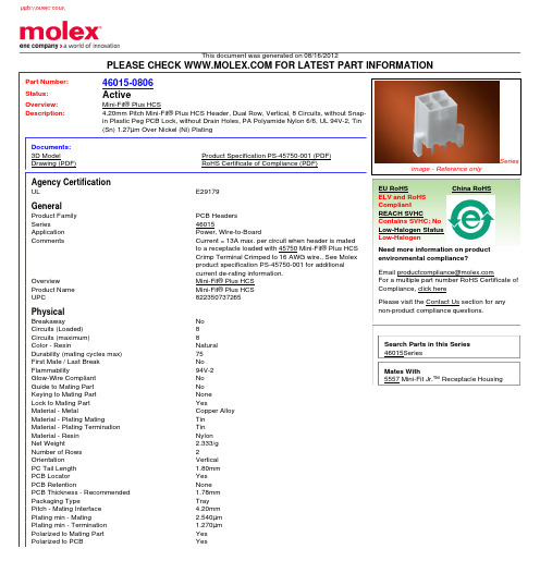
This document was generated on 08/16/2012PLEASE CHECK FOR LATEST PART INFORMATIONPart Number:46015-0806Status:ActiveOverview:Mini-Fit® Plus HCSDescription:4.20mm Pitch Mini-Fit® Plus HCS Header, Dual Row, Vertical, 8 Circuits, without Snap-in Plastic Peg PCB Lock, without Drain Holes, PA Polyamide Nylon 6/6, UL 94V-2, Tin (Sn) 1.27µm Over Nickel (Ni) PlatingDocuments:3D ModelProduct Specification PS-45750-001 (PDF)Drawing (PDF)RoHS Certificate of Compliance (PDF)Agency CertificationULE29179GeneralProduct Family PCB Headers Series46015Application Power, Wire-to-BoardCommentsCurrent = 13A max. per circuit when header is mated to a receptacle loaded with 45750 Mini-Fit® Plus HCS Crimp Terminal Crimped to 16 AWG wire., See Molex product specification PS-45750-001 for additional current de-rating information.OverviewMini-Fit® Plus HCS Product Name Mini-Fit® Plus HCS UPC822350737265PhysicalBreakawayNo Circuits (Loaded)8Circuits (maximum)8Color - ResinNatural Durability (mating cycles max)75First Mate / Last Break No Flammability94V-2Glow-Wire Compliant No Guide to Mating Part No Keying to Mating Part None Lock to Mating Part YesMaterial - MetalCopper Alloy Material - Plating MatingTin Material - Plating Termination Tin Material - Resin Nylon Net Weight2.333/g Number of Rows 2Orientation Vertical PC Tail Length 1.80mm PCB Locator Yes PCB RetentionNone PCB Thickness - Recommended 1.78mm Packaging TypeTray Pitch - Mating Interface 4.20mm Plating min - Mating2.540µm Plating min - Termination 1.270µm Polarized to Mating Part Yes Polarized to PCBYesSeriesimage - Reference onlyEU RoHSChina RoHSELV and RoHS Compliant REACH SVHCContains SVHC: No Low-Halogen Status Low-HalogenNeed more information on product environmental compliance?Email productcompliance@For a multiple part number RoHS Certificate of Compliance, click herePlease visit the Contact Us section for any non-product compliance questions.Search Parts in this Series 46015SeriesMates With5557 Mini-Fit Jr.™ Receptacle HousingShrouded FullyStackable NoSurface Mount Compatible (SMC)NoTemperature Range - Operating-40°C to +105°CTermination Interface: Style Through HoleElectricalCurrent - Maximum per Contact13AVoltage - Maximum600VSolder Process DataDuration at Max. Process Temperature (seconds)5Lead-free Process Capability Wave Capable (TH only)Max. Cycles at Max. Process Temperature1Process Temperature max. C260Material InfoReference - Drawing NumbersProduct Specification PS-45750-001Sales Drawing SD-46015-001This document was generated on 08/16/2012PLEASE CHECK FOR LATEST PART INFORMATION分销商库存信息: MOLEX 0460150806。
16475;中文规格书,Datasheet资料

C
B.
C.
F
E
18 in.
D.
D
E.
A B
F.
G.
22 in.
Specifications: Color Thickness Bursting Strength Electrical Properties: RTT(Point to Point) Charge Decay
KIT, FIELD SERVICE, VINYL, 18" x 22", RED
DESCO WEST: 3651 WALNUT AVE., CHINO, CA 91710 WEB SITE: PHONE (909) 627-8178 FAX (909) 627-7449 DESCO EAST: 90 HUDSON RD, CANTON, MA 02021-1407 PHONE (781) 821-8370 FA6 - 10E8 Ohms 0.01 Sec. 5000V to 0V 12% RH
per ANSI/ESD-S4.1 per FTMS 101C-4046.1
G
Dissipative worksurface slows charge removal; meets ANSI/ESD S20.20 worksurface required limit and recommendation of ANSI/ESD S4.1 For complete information on field service kits, ask for Technical Bulletin TB-2011.
© 2008 DESCO INDUSTRIES INC.
Employee Owned
19665;中文规格书,Datasheet资料

Dual-Wire Dual-Operator Programmable Monitor DescriptionThe patented* Desco Dual-Wire Dual-OperatorProgrammable Monitor monitors two operators and two ESD work worksurfaces eliminating the need for periodic Figure 1. Desco 19665 Dual-Wire Dual-Operator Programmable MonitorFeatures and ComponentsTECHNICAL BULLETIN TB-3019Made in theUnited States of AmericaFigure 2. Dual-Wire Dual-Operator Programmable CBDE FG H I J K LFRONT VIEWBACK VIEWOperation1. Monitoring of the operators will remain in the STANDBY condition until a wrist cord is plugged into the operator remote. STANDBY mode is indicated by a blinking yellow operator LED.10mm snap needs to pierce and clinch bottom side of mat. Snap needs to be at least 12" apart or 72" max. 10mm snap needs to pierce and clinch bottom side of mat. Snap needs to be at least 12" apart or 72" max.OPERATOR 1WORKSURFACEOPERATOR 2WORKSURFACE10mm PUSH & CLINCH SNAP10mm PUSH & CLINCH SNAPBENCH GROUNDMAT 1 WIRING WHITE CABLEMAT 2 WIRING BLACK CABLEWRIST STRAP MONITORWRIST STRAP MONITORELECTRIC GROUNDOPERATOR 2REMOTE JACK BLACK CABLEOPERATOR 2REMOTE JACK WHITE CABLE Screw allows ground cord to be bolted to mat; keeps cord from disconnecting.Figure 3. Installing the Dual-Wire Dual-Operator Programmable MonitorororFigure 4. Connecting a dual-wire wrist strap to the operator remoteSETTING THE OPERATOR TEST VOLTAGE AND TEST LIMITThe Dual-Wire Dual-Operator Monitor’s operator test voltage and high test limit can be set to different values. The operator test voltage can be set to either +5V or +8V, and the operator high test limit can be set to either 10 megohms or 35 megohms. The default voltage is +8V, and the default operator high test limit is 10 megohms. These settings are controlled by a set of 3 switches located inside the monitor’s enclosure.NOTE: Desco recommends re-calibration of the monitor should either setting be changed. See the “Calibration” section for more information.To gain access to these switches, remove the monitor’s cover and position the monitor so the PCB matches the orientation shown in Figure 5. Switches SW1 and SW2 control the operator test voltage. Switch SW3 controls the operator high test limit.Operator Test Voltage+5VSW1 Position: RIGHTSW2 Position: LEFT+8VSW1 Position: LEFTSW2 Position: RIGHTOperator High Test Limit10 megohmsSW3 Position: RIGHT35 megohmsSW3 Position: LEFTCalibrationFrequency of recalibration should be based on the critical nature of those ESD sensitive items handled and the risk of failure for the ESD protective equipment and materials. In general, Desco recommends that calibration be performed annually.Use the EMIT 50524 Limit Comparator for Dual-Wire Monitors to perform periodic testing (once every 6-12 months) of the Dual-Wire Dual-Operator Programmable Monitor. The Limit Comparator can be used on the shop floor within a few minutes virtually eliminating downtime, verifying that the monitor is operating within tolerances. See TB-6542 for more information.Figure 5. Switches SW1, SW2 and SW3 inside the monitor’s enclosure Figure 6. EMIT 50524 Limit Comparator for Dual-Wire MonitorsNIST CalibrationDesco provides a basic, National Institute of Standardsand Technology (NIST) traceable calibration for theproducts that we manufacture. This is sometimesreferred to as a Level 1 calibration.For more on National Institute of Standards andTechnology see:/index.htmlFor more information on the calibration that Desco’sprovides for products that we manufacture see:/Calibration.aspxSpecificationsOperating Voltage 12 VDCOperating Temperature 32°F - 104°F (0 - 40°C)Monitor Dimensions 4.4" x 4.7" x 2.1"(11.2cm x 11.9cm x 5.3cm)Monitor Weight 1.1 lbs (0.5 kg)TEST VOLTAGESOperator +8 V** or +5 VWorksurface 200 mVTEST LIMITSOperator Low Fail: < 1.72 megohmsPass: 2 - 9 megohms**High Fail: > 11.5 megohms**orPass: 2 - 30 megohmsHigh Fail: > 40 megohmsWorksurface Pass: < 3.5 megohmsFail: > 3.8 megohms**DefaultFigure 7. Operator Remote dimensionsReplacement remotes are available as EMIT itemnumbers 50525 and 50526.分销商库存信息: DESCO19665。
BGA2866,115;中文规格书,Datasheet资料

1. Product profile1.1General descriptionSilicon Monolithic Microwave Integrated Circuit (MMIC) wideband amplifier with internalmatching circuit in a 6-pin SOT363 plastic SMD package.1.2Features and benefitsInput internally matched to 50 ΩA gain of 23.2 dB at 250 MHz increasing to 24.3 dB at 2150 MHz Output power at 1 dB gain compression = 4 dBm Supply current = 17.4 mA at a supply voltage of 5 V Reverse isolation > 32 dB up to 2150 MHzGood linearity with low second order and third order products Noise figure = 3.8 dB at 950 MHz Unconditionally stable (K > 1)No output inductor required1.3ApplicationsLNB IF amplifiersGeneral purpose low noise wideband amplifier for frequencies betweenDC and 2.2GHz2. Pinning informationBGA2866MMIC wideband amplifierRev. 2 — 1 November 2010Product data sheetTable 1.PinningPin Description Simplified outline Graphic symbol1V CC 2, 5GND23RF_OUT 4GND16RF_IN132456sym052132, 5643. Ordering information4. Marking5. Limiting values6. Thermal characteristics7. CharacteristicsTable 2.Ordering informationType number Package NameDescriptionVersion BGA2866-plastic surface-mounted package; 6 leadsSOT363Table 3.MarkingType numberMarking code DescriptionBGA2866*ED* = - : made in Hong Kong * = p : made in Hong Kong * = W : made in China * = t : made in MalaysiaTable 4.Limiting valuesIn accordance with the Absolute Maximum Rating System (IEC 60134).Symbol Parameter Conditions Min Max Unit V CC supply voltage RF input AC coupled−0.5 5.5V I CC supply current -36mA P tot total power dissipation T sp = 90 °C -200mW T stg storage temperature −40+125°C T j junction temperature -125°C P drivedrive power-−15dBmTable 5.Thermal characteristics Symbol ParameterConditionsTyp Unit R th(j-sp)thermal resistance from junction to solder pointP tot =200mW; T sp =90°C300K/WTable 6.CharacteristicsV CC = 5.0 V; Z S = Z L = 50 Ω; P i = −40 dBm; T amb = 25 °C; measured on demo board; unless otherwise specified.Symbol Parameter ConditionsMin Typ Max Unit V CC supply voltage 4.5 5.0 5.5V I CCsupply current14.717.420.1mATable 6.Characteristics …continuedV CC = 5.0 V; Z S = Z L = 50 Ω; P i = −40 dBm; T amb = 25 °C; measured on demo board; unless otherwise specified.Symbol Parameter Conditions Min Typ Max Unit G p power gain f = 250 MHz22.623.223.8dBf = 950 MHz23.223.924.6dBf = 2150 MHz22.824.325.8dB RL in input return loss f = 250 MHz182022dBf=950MHz242628dBf = 2150 MHz111824dB RL out output return loss f = 250 MHz212630dBf=950MHz121314dBf = 2150 MHz101114dB ISL isolation f = 250 MHz406081dBf=950MHz414344dBf = 2150 MHz323537dB NF noise figure f = 250 MHz 3.4 3.9 4.4dBf = 950 MHz 3.4 3.8 4.2dBf = 2150 MHz 3.5 3.9 4.3dB B−3dB−3 dB bandwidth 3 dB below gain at 1GHz 3.1 3.3 3.4GHz K Rollett stability factor f = 250 MHz333537f = 950 MHz 3.8 4.1 4.4f = 2150 MHz 1.3 1.6 1.9P L(sat)saturated output power f = 250 MHz567dBmf = 950 MHz578dBmf = 2150 MHz245dBm P L(1dB)output power at 1 dB gain compression f = 250 MHz345dBmf = 950 MHz345dBmf = 2150 MHz134dBm IP3I input third-order intercept point P drive=−36dBm (for each tone)f1=250MHz; f2=251MHz−6−4−2dBmf1=950MHz; f2=951MHz−9−7−4dBmf1=2150MHz; f2=2151MHz−16−12−9dBm IP3O output third-order intercept point P drive=−36dBm (for each tone)f1=250MHz; f2=251MHz171921dBmf1=950MHz; f2=951MHz151720dBmf1=2150MHz; f2=2151MHz91215dBm P L(2H)second harmonic output power P drive=−33dBmf1H=250MHz; f2H=500MHz−53−51−49dBmf1H=950MHz; f2H=1900MHz−43−41−40dBm ΔIM2second-order intermodulation distance P drive=−36dBm (for each tone)f1=250MHz; f2=251MHz364758dBcf1=950MHz; f2=951MHz324355dBc8. Application informationFigure1 shows a typical application circuit for the BGA2866 MMIC. The device isinternally matched to 50 Ω and therefore does not need any external matching. The valueof the input and output DC blocking capacitors C2 and C3 should not be more than 100 pFfor applications above 100 MHz. However, when the device is operated below 100 MHz,the capacitor value should be increased.The 22 nF supply decoupling capacitor C1 should be located as close as possible to theMMIC.The PCB top ground plane, connected to pins 2, 4 and 5 must be as close as possible tothe MMIC, preferably also below the MMIC. When using via holes, use multiple via holesas close as possible to the MMIC.8.1Application examples8.2Graphs8.3TablesTable 7.Supply current over temperature and supply voltagesTypical values.Symbol Parameter Conditions T amb (°C)Unit−402585I CC supply current V CC=4.5V16.4115.2714.36mAV CC=5.0V17.7316.6315.85mAV CC=5.5V19.2917.7317.27mA Table 8.Second harmonic output power over temperature and supply voltagesTypical values.Symbol Parameter Conditions T amb (°C)Unit−402585 P L(2H)second harmonic output power f = 250 MHz; P drive=−33dBmV CC=4.5V−48−49−51dBmV CC= 5.0V−49−51−53dBmV CC=5.5V−50−52−54dBmf = 950 MHz; P drive=−33dBmV CC=4.5V−40−41−42dBmV CC= 5.0V−40−41−42dBmV CC=5.5V−40−41−42dBmTable 9.Input power at 1 dB gain compression over temperature and supply voltages Typical values.Symbol Parameter Conditions T amb (°C)Unit−402585P i(1dB)input power at 1dB gain compression f = 250 MHzV CC=4.5V−18−18−19dBmV CC= 5.0V−18−18−18dBmV CC=5.5V−17−18−18dBmf = 950 MHzV CC=4.5V−19−19−19dBmV CC= 5.0V−18−18−19dBmV CC=5.5V−18−18−18dBmf = 2150 MHzV CC=4.5V−20−21−22dBmV CC= 5.0V−20−21−22dBmV CC=5.5V−20−21−22dBm Table 10.Output power at 1 dB gain compression over temperature and supply voltages Typical values.Symbol Parameter Conditions T amb (°C)Unit−402585P L(1dB)output power at 1dB gain compression f = 250 MHzV CC=4.5V433dBmV CC= 5.0V544dBmV CC=5.5V554dBmf = 950 MHzV CC=4.5V433dBmV CC= 5.0V544dBmV CC=5.5V654dBmf = 2150 MHzV CC=4.5V320dBmV CC= 5.0V421dBmV CC=5.5V431dBm分销商库存信息: NXPBGA2866,115。
7446632001;中文规格书,Datasheet资料
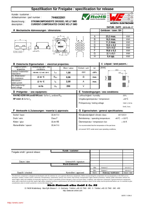
description :Gehäuse / case: SHA 23,3 max.mmB 18,5 max.mmC 11,5 max.mmD 10,0 ± 0,2mmE 5,0 ± 0,2mmF 19,6 ± 0,3mmG 2,1 ± 0,1mm H0,4 typ.mmEigenschaften / propertiesWert / valueEinheit / unittol.Leerlauf-Induktivität /inductanceDC-Widerstand /DC-resistance Nennstrom /rated current Nennspannung /rated voltage33%+20°CPrüfspannung / testing voltage1500 V, 50 Hz 5mA, 2 sec.SBaVersion 22010-05-17BKo Version 12009-02-17NameÄnderung / modificationDatum / dateÜbertemperatur / temperature rise: < 55 KKlimabeständigkeit/ climatic class: 40/125/21.............................................................Datum / dateCURRENT-COMPENSATED CHOKE WE-LF SMDmH R DC WAYNE KERR WK3260B/WK3265für/for L 0 und/and R DC U NI N Luftfeuchtigkeit / humidity:Class F Betriebstemp. / operating temperature: -40°C - +125°C HP 34401 A für/for I N...............................................................................2,00max.0,06±30%B Elektrische Eigenschaften / electrical properties:25050 HzUnterschrift / signatureKontrolliert / approvedWürth Elektronik.................................................................................................................................................................DATUM / DATE : 2010-05-17max.A Testbedingungen / testconditionsVΩA Mechanische Abmessungen / dimensions :100 kHz / 0,1 mA / 20°CC Lötpad / land pattern.:Umgebungstemperatur / temperature:L O 1,00D Prüfgeräte / test equipment:E Testbedingungen / test conditions:@ 20 °C @ 70 °C UL94 HB It is recommended that the temperature of the part does not exceed 125°C under worst case operating conditions.G Eigenschaften / general specifications:Sockel / base:Draht / wire:UL94 V-0F Werkstoffe & Zulassungen / material & approvals:Kleber / glue:Freigabe erteilt / general release:Kunde / customerAbstandhalter / spacer:UL94 V-0Würth Elektronik eiSos GmbH & Co. KGGeprüft / checked This electronic component is designed and developed with the intention for use in general electronics equipments. Before incorporating the components into any equipments in the field such as aerospace, aviation, nuclear control, submarine, transportation, (automotive control, train control, ship control), transportation signal, disaster prevention, medical, public information network etc. where higher safety and reliability are especially required or if there is possibility of direct damage or injury to human body.In addition, even electronic component in general electronic equipments, when used in electrical circuits that require high safety, reliability functions or performance, the sufficient reliability evaluation-check for the safety must be performed before use. It is essential to give consideration when to install a protective circuit at the design stage.[mm]description :SBaVersion 22010-05-17BKoVersion 12009-02-17NameÄnderung / modificationDatum / dateH Einfügungsdämpfung / insertion loss:Freigabe erteilt / general release:Geprüft / checked Kontrolliert / approvedDatum / dateWürth ElektronikWürth Elektronik eiSos GmbH & Co. KG.................................................................................................................................................................CURRENT-COMPENSATED CHOKE WE-LF SMDDATUM / DATE : 2010-05-17Unterschrift / signature ............................................................................................................................................Kunde / customer01020304050600,010,1110E i n f üg u n g s d äm p f u n g / i n s e r t i o n l o s s [d B ]Frequenz / frequency [MHz]typischer Dämpfungsverlauf / typical attenuation curveThis electronic component is designed and developed with the intention for use in general electronics equipments. Before incorporating the components into any equipments in the field such as aerospace, aviation, nuclear control, submarine, transportation, (automotive control, train control, ship control), transportation signal, disaster prevention, medical, public information network etc. where higher safety and reliability are especially required or if there is possibility of direct damage or injury to human body.In addition, even electronic component in general electronic equipments, when used in electrical circuits that require high safety, reliability functions or performance, the sufficient reliability evaluation-check for the safety must be performed before use. It is essential to give consideration when to install a protective circuit at the design stage.description :Gurtspezifikation / Tape specification:A24mmB4mmC44mma330 ± 2,0mmb21 ± 0,8mmc13 ± 0,5mmd150 ±1,0mme48,4mmf44mm165 to 180°SBa Version 22010-05-17BKo Version 12009-02-17NameÄnderung / modification Datum / date Datum / date Unterschrift / signatureWürth Elektronik.............................................................Geprüft / checked Kontrolliert / approvedWürth Elektronik eiSos GmbH & Co. KGI Rollenspezifikation / tape and reel specification:Rollenspezifikation / Reel specification: Freigabe erteilt / general release:Kunde / customer..................................................................................CURRENT-COMPENSATED CHOKE WE-LF SMDDATUM / DATE : 2010-05-17............................................................................... ...............................................................................The force for tearing off cover tape is10 to 130 grams in arrow directionfeeding directionØ ca b dA BefCThis electronic component is designed and developed with the intention for use in general electronics equipments. Before incorporating the components into any equipments in the field such as aerospace, aviation, nuclear control, submarine, transportation, (automotive control, train control, ship control), transportation signal, disaster prevention, medical, public information network etc. where higher safety and reliability are especially required or if there is possibility of direct damage or injury to human body.In addition, even electronic component in general electronic equipments, when used in electrical circuits that require high safety, reliability functions or performance, the sufficient reliability evaluation-check for the safety must be performed before use. It is essential to give consideration when to install a protective circuit at the design stage.分销商库存信息: WURTH-ELECTRONICS 7446632001。
742863160;中文规格书,Datasheet资料

3.1 3.0 2.02012-06-272012-03-292009-08-13SStSStSMuSStSMu-Würth Elektronik eiSos GmbH & Co. KGEMC & Inductive SolutionsMax-Eyth-Str. 174638 WaldenburgGermanyTel. +49 (0) 79 42 945 - 0A Dimensions: [mm]F Typical Impedance Characteristics:Test Equipment: E4991A or equivalentF Derating Curve:H1: Classification Reflow Profile for SMT components:H2: Classification Reflow ProfilesProfile FeaturePreheat- Temperature Min (T smin ) - Temperature Max (T smax ) - Time (t s ) from (T smin to T smax )Ramp-up rate (T L to T P )Liquidous temperature (T L )Time (t L ) maintained above T L Peak package body temperature (T p )Time within 5°C of actual peak temperature (t p )Ramp-down rate (T P to T L )Time 25°C to peak temperature Pb-Free Assembly 150°C 200°C60-180 seconds 3°C/ second max.217°C60-150 seconds See Table H320-30 seconds 6°C/ second max.8 minutes max.refer to IPC/JEDEC J-STD-020DH3: Package Classification Reflow TemperaturePB-Free Assembly PB-Free Assembly PB-Free Assembly Package Thickness< 1.6 mm 1.6 - 2.5 mm ≥ 2.5 mmVolume mm³<350260°C 260°C 250°CVolume mm³350 - 2000260°C 250°C 245°CVolume mm³>2000260°C 245°C 245°Crefer to IPC/JEDEC J-STD-020DH Soldering Specifications:I Cautions and Warnings:The following conditions apply to all goods within the product series of WE-CBF HFof Würth Elektronik eiSos GmbH & Co. KG:General:All recommendations according to the general technical specifications of the data-sheet have to be complied with.The disposal and operation of the product within ambient conditions which probably alloy or harm the component surface has to be avoided.If the product is potted in customer applications, the potting material might shrink during and after hardening. Accordingly to this the product is exposed to the pressure of the potting material with the effect that the ferrite body and termination is possibly damaged by this pressure and so the electrical as well as the mechanical characteristics are endanger to be affected. After the potting material is cured, the ferrite body and termination of the product have to be checked if any reduced electrical or mechanical functions or destructions have occurred.The responsibility for the applicability of customer specific products and use in a particular customer design is always within the authority of the customer. All technical specifications for standard products do also apply for customer specific products.Washing varnish agent that is used during the production to clean the application might damage or change the characteristics of the plating. The washing varnish agent could have a negative effect on the long term function of the product.Direct mechanical impact to the product shall be prevented as the ferrite material of the ferrite body could flake or in the worst case it could break.Product specific:Follow all instructions mentioned in the datasheet, especially:•The solder profile has to be complied with according to the technical reflow soldering specification, otherwise no warranty will be sustai-ned.• Wave soldering is only allowed after evaluation and approval.•All products are supposed to be used before the end of the period of 12 months based on the product date-code, if not a 100% solderabi-lity can´t be warranted.•Violation of the technical product specifications such as exceeding the nominal rated current will result in the loss of warranty.1. General Customer ResponsibilitySome goods within the product range of Würth Elektronik eiSos GmbH & Co. KG contain statements regarding general suitability for certain application areas. These statements about suitability are based on our knowledge and experience of typical requirements concerning the are-as, serve as general guidance and cannot be estimated as binding statements about the suitability for a customer application. The responsibi-lity for the applicability and use in a particular customer design is always solely within the authority of the customer. Due to this fact it is up to the customer to evaluate, where appropriate to investigate and decide whether the device with the specific product characteristics described in the product specification is valid and suitable for the respective customer application or not.2. Customer Responsibility related to Specific, in particular Safety-Relevant ApplicationsIt has to be clearly pointed out that the possibility of a malfunction of electronic components or failure before the end of the usual lifetime can-not be completely eliminated in the current state of the art, even if the products are operated within the range of the specifications.In certain customer applications requiring a very high level of safety and especially in customer applications in which the malfunction or failure of an electronic component could endanger human life or health it must be ensured by most advanced technological aid of suitable design of the customer application that no injury or damage is caused to third parties in the event of malfunction or failure of an electronic component.3. Best Care and AttentionAny product-specific notes, warnings and cautions must be strictly observed.4. Customer Support for Product SpecificationsSome products within the product range may contain substances which are subject to restrictions in certain jurisdictions in order to serve spe-cific technical requirements. Necessary information is available on request. In this case the field sales engineer or the internal sales person in charge should be contacted who will be happy to support in this matter.5. Product R&DDue to constant product improvement product specifications may change from time to time. As a standard reporting procedure of the Product Change Notification (PCN) according to the JEDEC-Standard inform about minor and major changes. In case of further queries regarding the PCN, the field sales engineer or the internal sales person in charge should be contacted. The basic responsibility of the customer as per Secti-on 1 and 2 remains unaffected.6. Product Life CycleDue to technical progress and economical evaluation we also reserve the right to discontinue production and delivery of products. As a stan-dard reporting procedure of the Product Termination Notification (PTN) according to the JEDEC-Standard we will inform at an early stage about inevitable product discontinuance. According to this we cannot guarantee that all products within our product range will always be available. Therefore it needs to be verified with the field sales engineer or the internal sales person in charge about the current product availability ex-pectancy before or when the product for application design-in disposal is considered.The approach named above does not apply in the case of individual agreements deviating from the foregoing for customer-specific products.7. Property RightsAll the rights for contractual products produced by Würth Elektronik eiSos GmbH & Co. KG on the basis of ideas, development contracts as well as models or templates that are subject to copyright, patent or commercial protection supplied to the customer will remain with Würth Elektronik eiSos GmbH & Co. KG.8. General Terms and ConditionsUnless otherwise agreed in individual contracts, all orders are subject to the current version of the “General Terms and Conditions of Würth Elektronik eiSos Group”, last version available at .J Important Notes:The following conditions apply to all goods within the product range of Würth Elektronik eiSos GmbH & Co. KG:分销商库存信息: WURTH-ELECTRONICS 742863160。
749119933;中文规格书,Datasheet资料
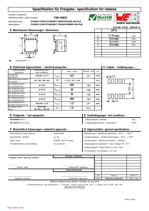
description := Marking Pin 133% Umgebungstemperatur / temperature:+20°CKontaktmaterial/ contact platingTBr 2006-06-12NameDatum / dateCo-Planarität / Co-Planarity: < 0,1 mmKontrolliert / approvedVersion 1Unterschrift / signatureÄnderung / modificationGeprüft / checked Würth Elektronik eiSos GmbH & Co.KG.................................................................................................Datum / dateG Eigenschaften / general specifications :Luftfeuchtigkeit / humidity:..................................................................................Schaltfrequenz / Switching frequency: 300 kHz Draht / wire:Basismaterial / base material:Ferrit/ ferrite 2UEWF 155°C or equiv.Spulenkörper / Bobbin Cu-Ag tinnedPOWER OVER ETHERNET-TRANSFORMER WE-PoEWK3260B für/for L F Werkstoffe & Zulassungen / material & approvals :D Prüfgeräte / test equipment :HP 34401 A für/for R DCAusgangsdaten / Output data: 2 x 3,3V / 2,0A Umgebungstemp. / ambient temperature: -40°C - + 85°C Eingangsspannungsbereich / Input Voltage: 36 - 57 V UL-V0Freigabe erteilt / general release:Kunde / customerWürth Elektronik..................................................................................D-74638 Waldenburg · Max-Eyth-Straße 1 - 3 · Germany · Telefon (+49) (0) 7942 - 945 - 0 · Telefax (+49) (0) 7942 - 945 - 400Betriebstemp. / operating temperature: -40°C - + 125°C E Testbedingungen / test conditions :description :POWER OVER ETHERNET-TRANSFORMER WE-PoEDATUM / DATE : 2006-06-12H Schaltbild / SchematicsTBr 2006-06-12NameDatum / dateWürth Elektronik eiSos GmbH & Co.KGD-74638 Waldenburg · Max-Eyth-Straße 1 - 3 · Germany · Telefon (+49) (0) 7942 - 945 - 0 · Telefax (+49) (0) 7942 - 945 - 400Freigabe erteilt / general release:Kunde / customerDatum / dateUnterschrift / signature Würth Elektronik..................................................Geprüft / checked Kontrolliert / approvedÄnderung / modification...................................................................................................................................................................................................................Version 1342178109description :POWER OVER ETHERNET-TRANSFORMER WE-PoE.....................................................................................................................................................................................................................................................................TBr 2006-06-12NameDatum / dateÄnderung / modificationVersion 1Freigabe erteilt / general release:Kunde / customerWürth ElektronikKontrolliert / approvedUnterschrift / signature Datum / dateGeprüft / checked D-74638 Waldenburg · Max-Eyth-Straße 1 - 3 · Germany · Telefon (+49) (0) 7942 - 945 - 0 · Telefax (+49) (0) 7942 - 945 - 400Würth Elektronik eiSos GmbH & Co.KGThe force for tearing off cover tape is 10 to 130 grams in arrow direction165 to 180°feeding directionThis electronic component has been designed and developed for usage in general electronic equipment. Before incorporating this component into any equipment where higher safety and reliability is especially required or if there is the possibility of direct damage or injury to human body, for example in the range of aerospace, aviation, nuclear control, submarine, transportation, (automotive control, train control, ship control), transportationsignal, disaster prevention, medical, public information network etc, Würth Elektronik eiSos GmbH must be informed before the design-in stage. In addition, sufficient reliability evaluation checks for safety must be performed on every electronic component which is used in electrical circuits that require high safety and reliability functions or performance.分销商库存信息: WURTH-ELECTRONICS 749119933。
0416620001;中文规格书,Datasheet资料
This document was generated on 08/20/2012PLEASE CHECK FOR LATEST PART INFORMATIONPart Number:41662-0001Status:ActiveDescription:3.96mm Pitch KK® Header, Breakaway, Right Angle, 2 Circuits, 0.38µm Gold (Au)Selective PlatingDocuments:3D ModelProduct Specification PS-08-50 (PDF)Drawing (PDF)RoHS Certificate of Compliance (PDF)Agency CertificationCSA LR19980ULE29179GeneralProduct Family PCB Headers Series41662ApplicationBoard-to-Board, Power, Wire-to-Board Application Tooling Part Link 011200901Product Name KK®UPC800753932340PhysicalBreakawayYes Circuits (Loaded)2Circuits (maximum)2Color - ResinBlack Durability (mating cycles max)50First Mate / Last Break No Flammability94V-0Glow-Wire Compliant No Guide to Mating Part No Keying to Mating Part None Lock to Mating Part None Material - MetalBrass Material - Plating Mating GoldMaterial - Resin Polyester Net Weight0.729/g Number of Rows 1Orientation Right Angle PC Tail Length 4.67mm PCB Locator No PCB RetentionNone PCB Thickness - Recommended 1.60mm Packaging TypeBag Pitch - Mating Interface3.96mm Pitch - Termination Interface 3.96mm Plating min - Mating 0.381µm Polarized to Mating Part Yes Polarized to PCB No Shrouded Partial StackableNoTemperature Range - Operating 0°C to +75°C Termination Interface: StyleThrough Hole ElectricalCurrent - Maximum per Contact7ASeriesimage - Reference onlyEU RoHSChina RoHSELV and RoHS Compliant REACH SVHCContains SVHC: No Low-Halogen Status Not Low-HalogenNeed more information on product environmental compliance?Email productcompliance@For a multiple part number RoHS Certificate of Compliance, click herePlease visit the Contact Us section for any non-product compliance questions.Search Parts in this Series 41662SeriesMates With2139 KK® Crimp Housing, 41695 KK®Crimp Housing, 6442 KK® Crimp Housing,2145 PCB Connector, 41815 PCB Connector, 3069 KK® Crimp HousingVoltage - Maximum250VSolder Process DataDuration at Max. Process Temperature (seconds)5Lead-free Process Capability Wave Capable (TH only)Max. Cycles at Max. Process Temperature1Process Temperature max. C235Material InfoOld Part Number A-41662-B02Y208Reference - Drawing NumbersProduct Specification PS-08-50Sales Drawing SD-41662-001This document was generated on 08/20/2012PLEASE CHECK FOR LATEST PART INFORMATION分销商库存信息: MOLEX 0416620001。
3656;中文规格书,Datasheet资料

/
分销商库存信息:
EBM-PAPST 3656
Mass Dimensions Material of impeller Housing material Direction of air flow Direction of rotation Bearing Lifetime L10 at 40 °C Lifetime L10 at maximum temperature Connection line Motor protection Approval
Web data sheet XI · Page 2 of 4 ebm-papst St. Georgen GmbH & Co. KG · Hermann-Papst-Straße 1 · D-78112 St. Georgen · Phone +49 7724 81-0 · Fax +49 7724 81-1309 · info2@ ·
/
3656
AC axial compact fan
Product drawing
Web data sheet XI · Page 3 of 4 ebm-papst St. Georgen GmbH & Co. KG · Hermann-Papst-Straße 1 · D-78112 St. Georgen · Phone +49 7724 81-0 · Fax +49 7724 81-1309 · info2@ ·
Nominal data
Type Phase Nominal voltage Frequency Speed Power input Min. ambient temperature Max. ambient temperature Air flow Sound power level Sound pressure level VAC Hz min-1 W °C °C m3/h B dB(A) 3656 1~ 230 50 2700 12.0 -40 75 75 4.9 37
Dell EMC PowerEdge XE7440 技术规格说明书
Dell EMC PowerEdge XE7440技术规格注意、小心和警告:“注意”表示帮助您更好地使用该产品的重要信息。
:“小心”表示可能会损坏硬件或导致数据丢失,并告诉您如何避免此类问题。
:“警告”表示可能会导致财产损失、人身伤害甚至死亡。
© 2020 Dell Inc. 或其子公司。
保留所有权利。
Dell、EMC 和其他商标是 Dell Inc. 或其附属机构的商标。
其他商标可能是其各自所有者的商标。
章 1: PowerEdge XE7440 概览 (4)章 2: 技术规格 (5)PowerEdge XE7440 底座的尺寸 (5)机箱重量 (6)处理器规格 (6)冷却规格 (6)支持的操作系统 (7)系统电池 (7)扩展总线规格 (7)内存规格 (8)驱动器和存储规格 (8)视频规格 (8)环境规格 (8)标准操作温度规格 (9)扩展操作温度规格 (9)微粒和气体污染规格 (10)最大振动规格 (10)最大撞击规格 (10)最大海拔高度规格 (11)章 3: 系统诊断程序和指示灯代码 (12)NIC 指示灯代码 (12)使用系统诊断程序 (12)Dell 嵌入式系统诊断程序 (12)章 4: 说明文件资源 (14)章 5: 获取帮助 (16)联系 Dell EMC (16)说明文件反馈 (16)通过使用 QRL 访问系统信息 (16)适用于 XE7100、XE7420 和 XE7440 系统的快速资源定位符 (17)通过 SupportAssist 接收自动支持 (17)回收或停售服务信息 (17)目录3PowerEdge XE7440 概览PowerEdge XE7440 服务器是 1U 服务器,支持:●两个英特尔至强 Cascade Lake 可扩展处理器(高达 150 W),每个处理器 26 核●16 DDR4 RDIMM 和低负载 DIMM●FE1 卡,以提高闪存分层●用于扩展和连接的 PCIe 和打开计算项目 (OCP) 适配器:带结构连接器的英特尔至强可扩展处理器也称为本地 Omnipath。
0190670098;0190670099;中文规格书,Datasheet资料
This document was generated on 08/09/2012PLEASE CHECK FOR LATEST PART INFORMATIONPart Number:19067-0098Status:ActiveOverview:Ring Tongue - Spade TerminalsDescription:NylaKrimp™ Funnel Entry Ring Tongue Terminal for 2 AWG Wire, Stud Size 5/16" (M8)Documents:Drawing (PDF)Product Specification PS-19902-016 (PDF)Product Specification PS-19902-011 (PDF)RoHS Certificate of Compliance (PDF)Product Specification PS-19902-013 (PDF)Agency CertificationCSA LR18689ULE32244GeneralProduct Family Ring and Spade Terminals Series19067Crimp Quality Equipment Yes Mil-Spec N/AOverviewRing Tongue - Spade Terminals Product Name NylaKrimp™Type RingUPC800753066793PhysicalBarrel Type Closed - Brazed Flammability 94V-2InsulationNylon (PA)Material - Plating Mating TinNet Weight15.424/g Packaging Type BagPlating min - Mating2.540µm Plating min - Termination 2.540µm Stud Size5/16" (M8)Termination Interface: Style Crimp or Compression Wire Insulation Diameter 15.24mm max.Wire Size AWG2Material InfoOld Part NumberG-975-56Reference - Drawing NumbersProduct Specification PS-19902-011, PS-19902-013, PS-19902-016Sales DrawingSD-19067-005Seriesimage - Reference onlyEU RoHSChina RoHSELV and RoHS Compliant REACH SVHC Not ReviewedLow-Halogen Status Not ReviewedNeed more information on product environmental compliance?Email productcompliance@For a multiple part number RoHS Certificate of Compliance, click herePlease visit the Contact Us section for any non-product compliance questions.Search Parts in this Series 19067SeriesApplication Tooling | FAQTooling specifications and manuals are found by selecting the products below.Crimp Height Specifications are then contained in the Application Tooling Specification document.GlobalDescription Product #Hand Crimp Tool 0640013900Putt Pump Dieless Head System0192860065Manual Putt Pump Hydraulic System,Die set required 0192860117Die Set (large) for the HHLS Hydraulic Crimper0192890010This document was generated on 08/09/2012PLEASE CHECK FOR LATEST PART INFORMATION/分销商库存信息:MOLEX01906700980190670099。
0460151206;中文规格书,Datasheet资料

This document was generated on 08/16/2012PLEASE CHECK FOR LATEST PART INFORMATIONPart Number:46015-1206Status:ActiveOverview:Mini-Fit® Plus HCSDescription:4.20mm Pitch Mini-Fit® Plus HCS Header, Dual Row, Vertical, 12 Circuits, without Snap-in Plastic Peg PCB Lock, without Drain Holes, PA Polyamide Nylon 6/6, UL 94V-2, Tin (Sn) 1.27µm Over Nickel (Ni) PlatingDocuments:3D ModelProduct Specification PS-45750-001 (PDF)Drawing (PDF)RoHS Certificate of Compliance (PDF)Agency CertificationULE29179GeneralProduct Family PCB Headers Series46015Application Power, Wire-to-BoardCommentsCurrent = 13A max. per circuit when header is mated to a receptacle loaded with 45750 Mini-Fit® Plus HCS Crimp Terminal Crimped to 16 AWG wire., See Molex product specification PS-45750-001 for additional current de-rating information.OverviewMini-Fit® Plus HCS Product Name Mini-Fit® Plus HCS UPC822350737449PhysicalBreakawayNo Circuits (Loaded)12Circuits (maximum)12Color - ResinNatural Durability (mating cycles max)75First Mate / Last Break No Flammability94V-2Glow-Wire Compliant No Guide to Mating Part No Keying to Mating Part None Lock to Mating Part YesMaterial - MetalCopper Alloy Material - Plating MatingTin Material - Plating Termination Tin Material - Resin Nylon Net Weight3.399/g Number of Rows 2Orientation Vertical PC Tail Length 1.80mm PCB Locator Yes PCB RetentionNone PCB Thickness - Recommended 1.78mm Packaging TypeTray Pitch - Mating Interface 4.20mm Plating min - Mating2.540µm Plating min - Termination 1.270µm Polarized to Mating Part Yes Polarized to PCBYesSeriesimage - Reference onlyEU RoHSChina RoHSELV and RoHS Compliant REACH SVHCContains SVHC: No Low-Halogen Status Low-HalogenNeed more information on product environmental compliance?Email productcompliance@For a multiple part number RoHS Certificate of Compliance, click herePlease visit the Contact Us section for any non-product compliance questions.Search Parts in this Series 46015SeriesMates With5557 Mini-Fit Jr.™ Receptacle HousingShrouded FullyStackable NoSurface Mount Compatible (SMC)NoTemperature Range - Operating-40°C to +105°CTermination Interface: Style Through HoleElectricalCurrent - Maximum per Contact13AVoltage - Maximum600VSolder Process DataDuration at Max. Process Temperature (seconds)5Lead-free Process Capability Wave Capable (TH only)Max. Cycles at Max. Process Temperature1Process Temperature max. C260Material InfoReference - Drawing NumbersProduct Specification PS-45750-001Sales Drawing SD-46015-001This document was generated on 08/16/2012PLEASE CHECK FOR LATEST PART INFORMATION分销商库存信息: MOLEX 0460151206。
- 1、下载文档前请自行甄别文档内容的完整性,平台不提供额外的编辑、内容补充、找答案等附加服务。
- 2、"仅部分预览"的文档,不可在线预览部分如存在完整性等问题,可反馈申请退款(可完整预览的文档不适用该条件!)。
- 3、如文档侵犯您的权益,请联系客服反馈,我们会尽快为您处理(人工客服工作时间:9:00-18:30)。
Bezeichnung :description := Start of winding Marking = Inductance code33% Umgebungstemperatur / temperature:+20°CFerrit / ferrite ME 08-11-24MST08-04-11ME 04-10-11NameDatum / dateVersion 4Änderung / modificationVersion 1Version 3..................................................................................Class HSn/Ag/Cu - 96.5/3.0/0.5%Geprüft / checked ...............................................................................................Freigabe erteilt / general release:Kunde / customerF Werkstoffe & Zulassungen / material & approvals :G Eigenschaften / general specifications :It is recommended that the temperature of the part does not exceed 125°C under worst case operating conditions.Endoberfläche / finishing electrode:Basismaterial / base material:Würth Elektronikhttp://www.we-online.deWürth Elektronik eiSos GmbH & Co. KGD-74638 Waldenburg · Max-Eyth-Strasse 1 - 3 · Germany · Telefon (+49) (0) 7942 - 945 - 0 · Telefax (+49) (0) 7942 - 945 - 400Kontrolliert / approvedDraht / wire:D Prüfgeräte / test equipment :Datum / date..................................................................................Unterschrift / signature E Testbedingungen / test conditions :Betriebstemp. / operating temperature: -40°C - + 125°C Umgebungstemp. / ambient temperature: -40°C - + 85°C Artikelnummer / part number : Luftfeuchtigkeit / humidity:SPEICHERDROSSEL WE-TPC POWER-CHOKE WE-TPCHP 34401 A für/for I DC und/and R DCHP 4274 A für/for L und/and SRF 744066151description :ME 08-11-24MST08-04-11ME 04-10-11NameDatum / dateVersion 4Änderung / modificationVersion 1Version 3http://www.we-online.deD-74638 Waldenburg · Max-Eyth-Strasse 1 - 3 · Germany · Telefon (+49) (0) 7942 - 945 - 0 · Telefax (+49) (0) 7942 - 945 - 400Würth Elektronik eiSos GmbH & Co. KGGeprüft / checked Kontrolliert / approvedWürth Elektronik...................................................................................................................................................................................................................................................................Datum / dateUnterschrift / signature H Induktivitätskurve / Inductance curve :Freigabe erteilt / general release:Kunde / customerPOWER-CHOKE WE-TPCDATUM / DATE : 2008-11-24description :a 330,0± 0,5mmb 20,20± 0,1mmc 13,00± 1,0mmd 100,0± 1,0mmME 08-11-24MST08-04-11ME 04-10-11NameDatum / dateDatum / dateUnterschrift / signatureWürth ElektronikVersion 3Version 4 http://www.we-online.de...............................................................................................Geprüft / checked Kontrolliert / approvedÄnderung / modificationVersion 1D-74638 Waldenburg · Max-Eyth-Strasse 1 - 3 · Germany · Telefon (+49) (0) 7942 - 945 - 0 · Telefax (+49) (0) 7942 - 945 - 400..................................................................................Würth Elektronik eiSos GmbH & Co. KG..................................................................................POWER-CHOKE WE-TPCRollenspezifikation / Reel specification:Freigabe erteilt / general release:Kunde / customerThis electronic component has been designed and developed for usage in general electronic equipment. Before incorporating this component into any equipment where higher safety and reliability is especially required or if there is the possibility of direct damage or injury to human body, for example in the range of aerospace, aviation, nuclear control, submarine, transportation, (automotive control, train control, ship control), transportation signal, disaster prevention, medical, public information network etc, Würth Elektronik eiSos GmbH must be informed before the design-in stage. In addition, sufficient reliability evaluation checks for safety must be performed on every electronic component which is used in electrical circuits that require high safety and reliability functions or performance.分销商库存信息: WURTH-ELECTRONICS 744066151。
