A1614WFCWWD4中文资料
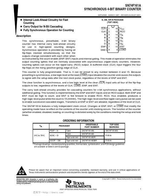
SN74F161ADRE4,SN74F161ADRG4,SN74F161ANSRE4,SN74F161ANSRG4,SN74F161ADE4, 规格书,Datasheet 资料
PACKAGING INFORMATIONOrderable Device Status(1)PackageType PackageDrawingPins PackageQtyEco Plan(2)Lead/Ball Finish MSL Peak Temp(3)SN74F161AD ACTIVE SOIC D1640Green(RoHS&no Sb/Br)CU NIPDAU Level-1-260C-UNLIMSN74F161ADE4ACTIVE SOIC D1640Green(RoHS&no Sb/Br)CU NIPDAU Level-1-260C-UNLIMSN74F161ADG4ACTIVE SOIC D1640Green(RoHS&no Sb/Br)CU NIPDAU Level-1-260C-UNLIMSN74F161ADR ACTIVE SOIC D162500Green(RoHS&no Sb/Br)CU NIPDAU Level-1-260C-UNLIMSN74F161ADRE4ACTIVE SOIC D162500Green(RoHS&no Sb/Br)CU NIPDAU Level-1-260C-UNLIMSN74F161ADRG4ACTIVE SOIC D162500Green(RoHS&no Sb/Br)CU NIPDAU Level-1-260C-UNLIMSN74F161AN ACTIVE PDIP N1625Pb-Free(RoHS)CU NIPDAU N/A for Pkg Type SN74F161AN3OBSOLETE PDIP N16TBD Call TI Call TISN74F161ANE4ACTIVE PDIP N1625Pb-Free(RoHS)CU NIPDAU N/A for Pkg TypeSN74F161ANSR ACTIVE SO NS162000Green(RoHS&no Sb/Br)CU NIPDAU Level-1-260C-UNLIMSN74F161ANSRE4ACTIVE SO NS162000Green(RoHS&no Sb/Br)CU NIPDAU Level-1-260C-UNLIMSN74F161ANSRG4ACTIVE SO NS162000Green(RoHS&no Sb/Br)CU NIPDAU Level-1-260C-UNLIM(1)The marketing status values are defined as follows:ACTIVE:Product device recommended for new designs.LIFEBUY:TI has announced that the device will be discontinued,and a lifetime-buy period is in effect.NRND:Not recommended for new designs.Device is in production to support existing customers,but TI does not recommend using this part in a new design.PREVIEW:Device has been announced but is not in production.Samples may or may not be available.OBSOLETE:TI has discontinued the production of the device.(2)Eco Plan-The planned eco-friendly classification:Pb-Free(RoHS),Pb-Free(RoHS Exempt),or Green(RoHS&no Sb/Br)-please check /productcontent for the latest availability information and additional product content details.TBD:The Pb-Free/Green conversion plan has not been defined.Pb-Free(RoHS):TI's terms"Lead-Free"or"Pb-Free"mean semiconductor products that are compatible with the current RoHS requirements for all6substances,including the requirement that lead not exceed0.1%by weight in homogeneous materials.Where designed to be soldered at high temperatures,TI Pb-Free products are suitable for use in specified lead-free processes.Pb-Free(RoHS Exempt):This component has a RoHS exemption for either1)lead-based flip-chip solder bumps used between the die and package,or2)lead-based die adhesive used between the die and leadframe.The component is otherwise considered Pb-Free(RoHS compatible)as defined above.Green(RoHS&no Sb/Br):TI defines"Green"to mean Pb-Free(RoHS compatible),and free of Bromine(Br)and Antimony(Sb)based flame retardants(Br or Sb do not exceed0.1%by weight in homogeneous material)(3)MSL,Peak Temp.--The Moisture Sensitivity Level rating according to the JEDEC industry standard classifications,and peak solder temperature.Important Information and Disclaimer:The information provided on this page represents TI's knowledge and belief as of the date that it is provided.TI bases its knowledge and belief on information provided by third parties,and makes no representation or warranty as to the accuracy of such information.Efforts are underway to better integrate information from third parties.TI has taken and continues to take reasonable steps to provide representative and accurate information but may not have conducted destructive testing or chemical analysis on incoming materials and chemicals.TI and TI suppliers consider certain information to be proprietary,and thus CAS numbers and other limited information may not be available for release.In no event shall TI's liability arising out of such information exceed the total purchase price of the TI part(s)at issue in this document sold by TI to Customer on an annual basis.TAPE AND REEL INFORMATION*All dimensions are nominalDevicePackage Type Package Drawing Pins SPQReel Diameter (mm)Reel Width W1(mm)A0(mm)B0(mm)K0(mm)P1(mm)W (mm)Pin1Quadrant SN74F161ADR SOIC D 162500330.016.4 6.510.3 2.18.016.0Q1SN74F161ANSRSONS162000330.016.48.210.52.512.016.0Q1*All dimensions are nominalDevice Package Type Package Drawing Pins SPQ Length(mm)Width(mm)Height(mm) SN74F161ADR SOIC D162500333.2345.928.6SN74F161ANSR SO NS162000367.0367.038.0IMPORTANT NOTICETexas Instruments Incorporated and its subsidiaries(TI)reserve the right to make corrections,enhancements,improvements and other changes to its semiconductor products and services per JESD46C and to discontinue any product or service per JESD48B.Buyers should obtain the latest relevant information before placing orders and should verify that such information is current and complete.All semiconductor products(also referred to herein as“components”)are sold subject to TI’s terms and conditions of sale supplied at the time of order acknowledgment.TI warrants performance of its components to the specifications applicable at the time of sale,in accordance with the warranty in TI’s terms and conditions of sale of semiconductor products.Testing and other quality control techniques are used to the extent TI deems necessary to support this warranty.Except where mandated by applicable law,testing of all parameters of each component is not necessarily performed.TI assumes no liability for applications assistance or the design of Buyers’products.Buyers are responsible for their products and applications using TI components.To minimize the risks associated with Buyers’products and applications,Buyers should provide adequate design and operating safeguards.TI does not warrant or represent that any license,either express or implied,is granted under any patent right,copyright,mask work right,or other intellectual property right relating to any combination,machine,or process in which TI components or services are rmation published by TI regarding third-party products or services does not constitute a license to use such products or services or a warranty or endorsement e of such information may require a license from a third party under the patents or other intellectual property of the third party,or a license from TI under the patents or other intellectual property of TI.Reproduction of significant portions of TI information in TI data books or data sheets is permissible only if reproduction is without alteration and is accompanied by all associated warranties,conditions,limitations,and notices.TI is not responsible or liable for such altered rmation of third parties may be subject to additional restrictions.Resale of TI components or services with statements different from or beyond the parameters stated by TI for that component or service voids all express and any implied warranties for the associated TI component or service and is an unfair and deceptive business practice. TI is not responsible or liable for any such statements.Buyer acknowledges and agrees that it is solely responsible for compliance with all legal,regulatory and safety-related requirements concerning its products,and any use of TI components in its applications,notwithstanding any applications-related information or support that may be provided by TI.Buyer represents and agrees that it has all the necessary expertise to create and implement safeguards which anticipate dangerous consequences of failures,monitor failures and their consequences,lessen the likelihood of failures that might cause harm and take appropriate remedial actions.Buyer will fully indemnify TI and its representatives against any damages arising out of the use of any TI components in safety-critical applications.In some cases,TI components may be promoted specifically to facilitate safety-related applications.With such components,TI’s goal is to help enable customers to design and create their own end-product solutions that meet applicable functional safety standards and requirements.Nonetheless,such components are subject to these terms.No TI components are authorized for use in FDA Class III(or similar life-critical medical equipment)unless authorized officers of the parties have executed a special agreement specifically governing such use.Only those TI components which TI has specifically designated as military grade or“enhanced plastic”are designed and intended for use in military/aerospace applications or environments.Buyer acknowledges and agrees that any military or aerospace use of TI components which have not been so designated is solely at the Buyer's risk,and that Buyer is solely responsible for compliance with all legal and regulatory requirements in connection with such use.TI has specifically designated certain components which meet ISO/TS16949requirements,mainly for automotive ponents which have not been so designated are neither designed nor intended for automotive use;and TI will not be responsible for any failure of such components to meet such requirements.Products ApplicationsAudio /audio Automotive and Transportation /automotiveAmplifiers Communications and Telecom /communicationsData Converters Computers and Peripherals /computersDLP®Products Consumer Electronics /consumer-appsDSP Energy and Lighting /energyClocks and Timers /clocks Industrial /industrialInterface Medical /medicalLogic Security /securityPower Mgmt Space,Avionics and Defense /space-avionics-defense Microcontrollers Video and Imaging /videoRFID OMAP Mobile Processors /omap TI E2E Community Wireless Connectivity /wirelessconnectivityMailing Address:Texas Instruments,Post Office Box655303,Dallas,Texas75265Copyright©2012,Texas Instruments Incorporated。
AIP1628 LED驱动控制专用电路说明书
江苏省无锡市蠡园经济开发区滴翠路100号9栋2层 第 1 页 共 12 页http://www.i-core. cn 邮编:214072 版本:2012-01-B1AIP1628LED 驱动控制专用电路产品说明书说明书发行履历:版本 发行时间新制/修订内容2010-01-A 2010-01 更换新模板2012-01-B12012-01增加说明书编号及发行履历深圳富瑞世嘉 中微爱芯一级代理手机(微信):13530167943网 址:www.forchip.cn1、概述AIP1628是带键盘扫描接口的LED驱动控制专用电路,内部集成有MCU数字接口、数据锁存器、键盘扫描等电路。
本产品主要应用于VCR、VCD、DVD及家庭影院等产品的显示屏驱动。
其主要特点如下:●采用功率CMOS工艺●显示模式(10段×7位~13段×4位)●键扫描(10×2bit)●辉度调节电路(占空比8级可调)●串行接口(CLK,STB,DIO)●内置RC振荡(450KHz±5%)●内置上电复位电路●封装形式:SOP28一级代理943n江苏省无锡市蠡园经济开发区滴翠路100号9栋2层 第 3 页 共 12 页http://www.i-core. cn 邮编:214072版本:2012-01-B13 时钟输入CLK在上升沿读取串行数据,下降沿输出数据。
4 片选 STB在上升或下降沿初始化串行接口,随后等待接收指令。
STB 为低后的第一个字节作为指令,当处理指令时,当前其它处理被终止。
当STB 为高时,CLK 被忽略。
5 键扫数据输入 K1 输入该脚的数据在显示周期结束后被锁存6 键扫数据输入 K2 输入该脚的数据在显示周期结束后被锁存7 逻辑电源 VDD 电源电压8 输出(段) SEG1/KS1 段输出(也用作键扫描),P 管开漏输出。
9 输出(段) SEG2/KS2 段输出(也用作键扫描),P 管开漏输出。
E3643A中文资料(Agilent(Hewlett-Packard))中文数据手册「EasyDatasheet - 矽搜」

防护
一年E364xA系列电源
三个月标准运附件
产品监管
设计符合UL3111-1;认证,CSA 22.2 1010.1号; 符合IEC 1010-1;符合EMC指令89/336/EEC(第1组,A类)
订购信息
安捷伦E364xA系列电源 E3640A 30瓦单电源 E3641A 30瓦单电源 E3642A 50瓦单电源 E3643A 50瓦单电源 E3644A 80瓦单电源 E3645A 80瓦单电源 E3646A 60瓦双电源 E3647A 60瓦双电源 E3648A 100瓦双电源 E3649A 100瓦双电源
E3640A
E3641A
E3642A
E3643A
E3644A
E3645A
30 W
50 W
80 W
1
0至8 V / 3 A或 0 to 20 V/1.5 A
5.3千克
1
0〜35 V / 0.8 A或 0 to 60 V/0.5 A
5.2千克
1
0至8 V / 5 A或 0 to 20 V/2.5 A
6.3千克
*与1CM或锁定链接机架安装/ FL法兰套件需要
安捷伦或客户支持轨
安捷伦支持RailsE3663AC
5
(标准命令 可编程仪器)允许快速和简单编程程
序. 此外,用户手册,为所有最终用户 编程足够信息,从初学者到退伍军人 .
广泛支持
VXI 即插即用 软件驱动程序 适用于VEE,国家 仪器公司LabVIEW and LabWin dows .有这些驱动程序, 整合E364xA到您 系统不能有任何容易.该
驱动程序在微软支持
准确度 编程 电压
12个 月
(@ 25ºC±5°C),±(%输出+偏移)
MAX16143、MAX16145、MAX16147和MAX16149监控芯片说明书

MAX16147WM75SA+MAX16147WM75SA+TGeneral DescriptionThe MAX16143, MAX16145, MAX16147, and MAX16149 are supervisory circuits that monitor their own supply voltages using a factory-set reset threshold that ranges from +2.3V to +11.6V. A manual reset (MR or MR ) input is included. The RESET (or RESET ) output has options for active-low, active-high, push-pull, or open-drain. The reset output asserts when the monitored voltage falls below the threshold voltage, and remains asserted until the monitored voltage has exceeded its threshold (plus hysteresis) for a time equal to the factory-set reset time-out period. Available reset timeout periods range from 30µs to 4.2s.The 5-pin SOT23 and 4-bump wafer-level packages (WLPs) offer compatibility with space-constrained environments. These ICs are fully specified over the -40°C to +125°C temperature range.Applications●Servers●Communications Equipment ●Industrial EquipmentOrdering Information appears at end of data sheet.19-100361; Rev 1; 6/18Benefits and Features●Factory-Set Reset Threshold Options from +2.3V to+11.6V ●Manual Reset Input• Active-High and Active-Low Trigger Options • Optional Internal Pullup or Pulldown• Fast (45µs) and Slow (50ms) Debounce Time Options ●Guaranteed Reset Valid to V CC ≥ 1.3V●Push-Pull and Open-Drain Reset Output Options• M AX16143: Open-Drain, Active-Low • MAX16145: Open-Drain, Active-High • MAX16147: Push-Pull, Active-Low • MAX16149: Push-Pull, Active-High ●Power-Supply Transient Immunity●-40°C to +125°C Operating Temperature Range ●SOT23-5 Package and 4-Bump WLPsSimplified Block DiagramClick here for production status of specific part numbers.MAX16143/MAX16145/MAX16147/MAX16149High-Voltage Supervisors with Manual Reset InputEVALUATION KIT AVAILABLEV CC to GND ..........................................................-0.3V to +15V MR or MR to GND .............-0.3V to lower of VCC + 0.3 or 6.0 V RESET or RESET to GND ....-0.3V to lower of V CC +0.3 or 6.0V Input/Output Current (All pins) ........................-20mA to +20mA Continuous Power Dissipation (Multilayer Board, SOT23, T A = +70°C, derate 3.9mW/°Cabove +70°C.) .............................................................312.6mWContinuous Power Dissipation (Multilayer Board,WLP , T A = +70°C, derate 9.7mW/°C above +70°C.) ....776mW Operating Temperature Range .........................-40°C to +125°C Storage Temperature Range ............................-65°C to +150°CSOT-23PACKAGE CODEU5+1Outline Number 21-0057Land Pattern Number90-0174Thermal Resistance, Single-Layer Board:Junction to Ambient (θJA )324.3Junction to Case (θJC )82Thermal Resistance, Four-Layer Board:Junction to Ambient (θJA )255.9Junction to Case (θJC )81WLPPACKAGE CODEW40E0+1Outline Number 21-100215Land Pattern NumberSee App Note 1891Thermal Resistance, Four-Layer Board:Junction to Ambient (θJA )103°C/W Junction to Case (θJC )N/A Absolute Maximum RatingsStresses beyond those listed under “Absolute Maximum Ratings” may cause permanent damage to the device. These are stress ratings only, and functional operation of the device at these or any other conditions beyond those indicated in the operational sections of the specifications is not implied. Exposure to absolute maximum rating conditions for extended periods may affect device reliability.Package thermal resistances were obtained using the method described in JEDEC specification JESD51-7, using a four-layer board. For detailed information on package thermal considerations, refer to /thermal-tutorial .For the latest package outline information and land patterns (footprints), go to /packages . Note that a “+”, “#”, or “-” in the package code indicates RoHS status only. Package drawings may show a different suffix character, but the drawing pertains to the package regardless of RoHS status.Package InformationMAX16143/MAX16145/ MAX16147/MAX16149High-Voltage Supervisors with Manual Reset Input(V CC = 2.3V to 14V, T J = T A = -40°C to +125°C, Typical values are at T A = 25°C unless otherwise noted. Limits over the operating temperature range and relevant supply voltage range are guaranteed by design, test, and characterization.)Note 2: Correct reset output voltage is guaranteed down to V CC = 1.3V.Note 3: During power-up, the internal regulator takes 2ms. Power-up time must be added to reset timeout period.PARAMETERSYMBOL CONDITIONSMIN TYPMAX UNITSOperating Voltage RangeV CCCorrect threshold detection3.314V MAX16143, MAX16147 (active-low). Correct reset state for supply ramp time ≥ 20µs. (Note 2) 1.314MAX16145, MAX16149 (active-high). Correct reset state for supply ramp time ≥ 1ms.214Supply CurrentI CC V CC ≤ V TH + 150mV2555µA Reset Threshold AccuracyV TH_ACC-1.5+1.5%Reset Threshold HysteresisHysteresis option Q, V CC rising0.5%V THHysteresis option R, V CC rising 1Hysteresis option S, V CC rising 3Hysteresis option T, V CC rising5V CC to Reset Output Delay t RDV CC falling at 10mV/µs from (V CC + 100mV) to (V CC - 100mV)15µs Reset Timeout Period Accuracy (Note 3)Variation from nominal t RP -25+25%Output Voltage Low V OL V CC ≥ 1.7V, I SINK = 3.2mA 0.4V 1.3V ≤ V CC < 1.7V, I SINK = 100µA 0.4Output Voltage High V OH MAX16147/MAX16149, I SOURCE = 10μA 2.4 3.15V Output CurrentI OH V OH = 2.5V255080µA Open-Drain Output Leakage CurrentMAX16143/MAX161451µA Manual Reset Debounce Timet DB Active-low or active-high manual reset 4570µs 5070ms Manual Reset Minimum Input Pulse Width t PW Edge-triggered manual reset option.—µs MR Internal Pullup Resis-tanceR PU MR option F or H 50kΩMR Internal Pulldown Re-sistanceR PD MR option B or D 50kΩInput Voltage Low V IL MR, MR 0.7V Input Voltage High V IH MR, MR1.7V Input CurrentMR, MR . Internal pullup resistor not connected.-150+150nA Electrical CharacteristicsMAX16143/MAX16145/ MAX16147/MAX16149High-Voltage Supervisors with Manual Reset Input(T A = 25°C unless otherwise noted.)Typical Operating CharacteristicsMAX16143/MAX16145/ MAX16147/MAX16149High-Voltage Supervisors with Manual Reset Input(T A = 25°C unless otherwise noted.)Typical Operating Characteristics (continued)1101001000MAXIMUM V CC TRANSIENT DURATION vs. OVERDRIVEtoc112V/div20ms/divRST 2V/div 2V/divV CC = 12Vtoc09MAX16143/MAX16145/ MAX16147/MAX16149High-Voltage Supervisors with Manual Reset Input(T A = 25°C unless otherwise noted.)Typical Operating Characteristics (continued)toc162ms/divV CC RISE TIME = 10ms1V/divRESETtoc14500µs/div1V/divV BACKUPV CC RISE TIME = 100µs1V/divRESETtoc1720ms/div1V/divCCV CC RISE TIME = 100ms1V/divtoc151V/divV CC RISE TIME = 1msMAX16143/MAX16145/ MAX16147/MAX16149High-Voltage Supervisors with Manual Reset InputPINNAME FUNCTIONSOT23WLP 1A1RESET, RESET Reset Output. RESET asserts when V CC falls below the factory-set threshold or when the manual reset is triggered. RESET deasserts after the factory-set reset timeout when V CC goes above its set threshold or when MR is released.2, 4B2GND Ground3B1MR, MR Manual Reset Input. See Manual Reset Input section for more detail.5A2V CCSupply Voltage Input. Bypass V CC to ground with a 0.1µF capacitor.Pin ConfigurationPin DescriptionMAX16143/MAX16145/ MAX16147/MAX16149High-Voltage Supervisors with Manual Reset InputDetailed DescriptionThe MAX16143/MAX16145/MAX16147/MAX16149 aresupervisory circuits that monitor their V CC voltage from+2.3V to +11.6V using factory-set reset threshold andoffer manual reset capability. The MAX16143/MAX16145feature an open-drain reset output, while the MAX16147/MAX16149 feature a push-pull reset output. The resetoutput asserts and remains asserted for the reset timeoutafter the V CC voltage exceeds its threshold. All devicesare offered with reset timeout periods ranging from 30μsto 4200ms. See Table 1 for available options. The resetoutput is guaranteed to be in valid logic state down toV CC = 1.3V.V CC ThresholdThe MAX16143/MAX16145/MAX16147/MAX16149operate with a V CC supply voltage from +3.3V to +14V,with monitoring range of +2.3V to +11.6V. V CC has arising threshold of V TH + V HYST and a falling thresholdof V TH. See Tables 2 and 3 for available threshold andhysteresis options. When V CC rises above V TH + V HYSTand the manual reset input is in an inactive state, RESETdeasserts after the reset timeout period (t RP). See thetiming diagram in Figure 1. When V CC falls below V TH,the reset output asserts low after a fixed delay (t RD).Table 1. Reset Timeout OptionsTable 2. V CC Threshold OptionsSUFFIXRESET TIMEOUTPERIODUNIT T A = 25°CT A = -40°Cto +125°CTYP MIN MAXA30——µs B 1.50 1.125 1.875ms C3 2.25 3.75ms D6 4.57.5ms E12915ms F241830ms G5037.562.5ms H10075125ms I150112.5187.5ms J225168.8281.3ms K300225375ms L450337.5562.5ms M600450750ms N10007401250ms O200015002500ms P420031505250ms SUFFIX1.5%UNITTYP MIN MAXY611.48411.60011.716V Y511.38511.50011.615V Y411.28611.40011.514V Y311.18711.30011.413V Y211.08811.20011.312V Y110.98911.10011.211V Y010.8911.00011.11V X710.59310.70010.807V X610.49410.600107.06V X510.39510.50010.605V 009.910.00010.1V 959.4059.5009.595V 908.919.0009.09V 858.4158.5008.585V 807.928.0008.08V 757.4257.5007.575V70 6.937.0007.07V65 6.435 6.500 6.565V60 5.94 6.000 6.06V55 5.445 5.500 5.555V48 4.752 4.800 4.848V47 4.653 4.700 4.747V46 4.554 4.600 4.646V45 4.455 4.500 4.545V44 4.356 4.400 4.444V43 4.257 4.300 4.343V42 4.158 4.200 4.242V41 4.059 4.100 4.141V40 3.960 4.000 4.040V39 3.861 3.900 3.939V38 3.762 3.800 3.838V37 3.663 3.700 3.737V36 3.564 3.600 3.636V35 3.465 3.500 3.535V34 3.366 3.400 3.434V33 3.267 3.300 3.333V32 3.168 3.200 3.232V31 3.069 3.100 3.131V30 2.970 3.000 3.030V29 2.871 2.900 2.929VMAX16143/MAX16145/ MAX16147/MAX16149High-Voltage Supervisors with Manual Reset InputReset OutputThe MAX16143/MAX16145 feature open-drain reset outputs, while the MAX16147/MAX16149 feature push-pull reset outputs. For proper operation, connect the reset output of the MAX16143 and the MAX16145 to V CC , or external voltage with a pullup resistor. The reset output of the MAX16147 and the MAX16149 are internally connected to a 2.5V or 3V regulator.Manual Reset InputThe MAX16143/MAX16145/MAX16147/MAX16149 include a manual reset input (MR, MR ) that allows initiating system reset using external signal or push-button switch. The manual reset input is available in active-low, active-high or edge-triggered option. The active-low (MR ) and active-high (MR) inputs feature either 45μs or 50ms debounce timing option to help filter out noise during manual reset transitioning from inactive to active state. In addition, the manual reset input is factory-programmable to have a pull up/pull down resistor or be left floating. See Table 4 and Table 5 for available options.Table 2. V CC Threshold Options (continued)Table 3. V CC Threshold Hysteresis OptionsTable 4. MAX16143/MAX16145 Manual Reset Configuration OptionsSUFFIX 1.5%UNIT TYP MIN MAX 28* 2.772 2.800 2.828V 27 2.673 2.700 2.727V 26* 2.574 2.600 2.626V 25 2.475 2.500 2.525V 24 2.376 2.400 2.424V 232.2772.3002.323VSUFFIX HYSTERSISQ 0.5%R 1%S 3%T5%SUFFIXLEVEL HIGH/LOWDEBOUNCE TIME (NA = EDGE TRIGGER)PULLUP/PULLDOWN A H 45µs NOT CONNECTEDB H 45µs PULLDOWNC H 50ms NOT CONNECTEDD H 50ms PULLDOWNE L 45µs NOT CONNECTEDF L 45µs PULLUPG L 50ms NOT CONNECTEDH L 50ms PULLUP J H N/A NOT CONNECT K H N/A PULLDOWN L L N/A NOT CONNECTEDMLN/APULL UPMAX16143/MAX16145/ MAX16147/MAX16149High-Voltage Supervisors with Manual Reset InputTable 5. MAX16147/MAX16149 Manual Reset and RESET Configuration OptionsSUFFIX LEVELHIGH/LOW DEBOUNCE TIME(NA = EDGETRIGGER)MR/MRPULLUP/PULLDOWNRESETPULLUPVOLTAGEA H45µs NOT CONNECTED3VB H45µs PULLDOWN3VC H50ms NOT CONNECTED3VD H50ms PULLDOWN3VE L45µs NOT CONNECTED3VF L45µs PULLUP3VG L50ms NOT CONNECTED3VH L50ms PULLUP3VJ H N/A NOT CONNECTED 2.5VK H N/A PULLDOWN 2.5VL H N/A NOT CONNECTED 2.5VM H N/A PULLUP 2.5VN L45µs NOT CONNECTED 2.5VO L45µs PULLUP 2.5VP L50ms NOT CONNECTED 2.5VQ L50ms PULLUP 2.5VR H N/A NOT CONNECTED3VS H N/A PULLDOWN3VT L N/A NOT CONNECTED3VU L N/A PULLUP3VV H N/A NOT CONNECTED 2.5VW H N/A PULLDOWN 2.5VX L N/A NOT CONNECTED 2.5VY L N/A PULLUP 2.5V MAX16147/MAX16149with Manual Reset InputApplications InformationReset OutputThe MAX16143/MAX16145/MAX16147/MAX16149 are microprocessor supervisory circuits that assert a reset to prevent code-execution errors during power-up, power-down, and brownout conditions. The reset output asserts when the V CC voltage falls below the factory-set threshold, V TH . The reset output de-asserts after the reset timeout (t RP ) when V CC voltage rises above the reset threshold plus the hysteresis voltage, (V TH + V HYST ). The reset output is guaranteed to be at the correct logic voltage for VCC voltage down to 1.3V. See Figure 1 for details.Manual Reset Input (MR)Many systems require manual reset capability, allowing the operator, a test technician, or external logic circuitry to initiate a reset. The MAX16143/MAX16145/MAX16147/MAX16149 provide this capability by featuring an manual reset input (MR). When a manual reset is initiated, the reset output asserts and remain asserted as long as the manual reset input is in active state. Reset deasserts after reset timeout when the manual reset input is released. Figure 1 shows the behavior of the manual reset configured as active-low, with 50kΩ pull (MR ). See Selector Guide for available options.Depending on the application, the manual reset input is factory-programmable to have either an internal pullup resistor, pulldown resistor of 50kΩ (typ), or be left floating.The pullup resistor allows the manual reset input to be left unconnected if not used. An external pullup resistor is required if the manual reset input option chosen does not have an internal pullup resistor. The maximum input voltage on MR is 5.5V.An alternative is to use a normally open momentary switch connected from MR (active-low) to GND, or from MR (active-high) to a logic-high voltage to create a manual-reset function. If a Long Debounce version is used, external debounce circuitry is not required, but an external pullup or pulldown will be required if a version without an internal resistor is used. If the manual reset input is driven from long cables, or the IC is used in a noisy environment, connect a 0.1μF capacitor from MR /MR to GND in order to provide additional noise immunity.Negative-Going V CC Transients ProtectionThese supervisory circuits are relatively immune to short-duration, negative-going V CC transients (glitches). The Maximum Transient Duration vs. Reset Threshold Overdrive graph (in the Typical Operating Characteristics section) shows the typical transient pulse width and amplitude required to trigger a reset. The reset threshold overdrive specifies how far the pulse falls below the actual reset threshold, and the maximum transient duration specifies the width of the pulse as it crosses the reset threshold. If a pulse occurs in the region above the curve, a reset triggers. If a pulse occurs in the region below the curve, a reset does not trigger.Figure 1. RESET and MR Timing DiagramMAX16147/MAX16149with Manual Reset InputMAX16147/MAX16149with Manual Reset Input*Future product—Contact factory for availability.+ Denotes a lead(Pb)-free/RoHS-compliant package. T Denotes tape-and-reel.PARTTEMP RANGE PIN-PACKAGEMAX16143_ _ _ _ _+T*-40°C to +125°C 4 WLP MAX16145_ _ _ _ _ T*-40°C to +125°C 4 WLP MAX16147WM75SA+T -40°C to +125°C 4 WLP MAX16149_ _ _ _ _T*-40°C to +125°C4 WLPTypical Application CircuitOrdering InformationMAX16147/MAX16149with Manual Reset InputREVISION NUMBERREVISION DATEDESCRIPTIONPAGES CHANGED06/18Initial release—16/18Updated Simplified Block Diagram and Ordering Information table1, 13Revision HistoryMaxim Integrated cannot assume responsibility for use of any circuitry other than circuitry entirely embodied in a Maxim Integrated product. No circuit patent licenses are implied. Maxim Integrated reserves the right to change the circuitry and specifications without notice at any time. The parametric values (min and max limits) shown in the Electrical Characteristics table are guaranteed. Other parametric values quoted in this data sheet are provided for guidance.MAX16147/MAX16149with Manual Reset InputFor pricing, delivery, and ordering information, please contact Maxim Direct at 1-888-629-4642, or visit Maxim Integrated’s website at .MAX16147WM75SA+MAX16147WM75SA+T。
AD9914_CN

DDS内核 ..................................................................................... 19 12位DAC输出............................................................................ 20 DAC校准输出............................................................................ 20 重构滤波器 ................................................................................ 20 时钟输入(REF_CLK/REF_CLK) ............................................ 21 PLL锁定指令.............................................................................. 22 输出幅度键控(OSK)................................................................. 22 数字斜坡发生器(DRG) ........................................................... 23 省电控制..................................................................................... 27 编程和功能引脚............................................................................. 28 串行编程 .......................................................................................... 31 控制接口——串行I/O.............................................................. 31 通用串行I/O操作...................................................................... 31 指令字节..................................................................................... 31 串行I/O端口引脚功能描述 .................................................... 31 串行I/O时序图 .......................................................................... 32 MSB/LSB传输 ............................................................................ 32 并行编程(8/16位)........................................................................... 33 寄存器图和位功能描述................................................................ 34 寄存器位功能描述 ................................................................... 39 外形尺寸 .......................................................................................... 45 订购指南..................................................................................... 45
常用三极管参数大全

玉林万顺达电脑芯片级维修资料 2010-07-20整理玉林万顺达电脑芯片级维修资料 2010-07-20整理玉林万顺达电脑芯片级维修资料 2010-07-20整理玉林万顺达电脑芯片级维修资料 2010-07-20整理玉林万顺达电脑芯片级维修资料 2010-07-20整理玉林万顺达电脑芯片级维修资料 2010-07-20整理玉林万顺达电脑芯片级维修资料 2010-07-20整理玉林万顺达电脑芯片级维修资料 2010-07-20整理玉林万顺达电脑芯片级维修资料 2010-07-20整理玉林万顺达电脑芯片级维修资料 2010-07-20整理玉林万顺达电脑芯片级维修资料 2010-07-20整理玉林万顺达电脑芯片级维修资料 2010-07-20整理玉林万顺达电脑芯片级维修资料 2010-07-20整理玉林万顺达电脑芯片级维修资料 2010-07-20整理玉林万顺达电脑芯片级维修资料 2010-07-20整理玉林万顺达电脑芯片级维修资料 2010-07-20整理玉林万顺达电脑芯片级维修资料 2010-07-20整理玉林万顺达电脑芯片级维修资料 2010-07-20整理玉林万顺达电脑芯片级维修资料 2010-07-20整理玉林万顺达电脑芯片级维修资料 2010-07-20整理玉林万顺达电脑芯片级维修资料 2010-07-20整理玉林万顺达电脑芯片级维修资料 2010-07-20整理玉林万顺达电脑芯片级维修资料 2010-07-20整理玉林万顺达电脑芯片级维修资料 2010-07-20整理玉林万顺达电脑芯片级维修资料 2010-07-20整理玉林万顺达电脑芯片级维修资料 2010-07-20整理玉林万顺达电脑芯片级维修资料 2010-07-20整理玉林万顺达电脑芯片级维修资料 2010-07-20整理玉林万顺达电脑芯片级维修资料 2010-07-20整理玉林万顺达电脑芯片级维修资料 2010-07-20整理。
四方综保电动机说明书精品文档24页
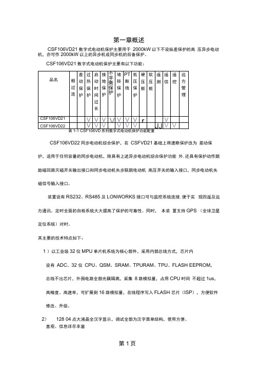
第一章概述CSF106VD21数字式电动机保护主要用于2000kW以下不设纵差保护的高压异步电动机,亦可作2000kW以上的异步机或同步机的后备保护。
CSF106VD21数字式电动机保护主要有以下功能:CSF106VD22同步电动机综合保护,在CSFVD21基础上将速断保护改为差动保护,适用于任何容量的同步电动机,除具有上述异步电动机综合保护功能外,还具有保护动作跳励磁回路灭磁开关输出接口和同步电动机失步联跳电动机高压开关的输入接口,同步电动机失磁信号输入接口。
装置设有RS232、RS485及LONWORKS接口可与监控系统连接,便于实现四遥及远方通讯。
定时全面的自检系统大大提高了保护的可靠性。
同时,本装置支持GPS (全球卫星定位系统)对时。
其主要的技术特点如下:1 )以工业级32位MPU单片机系统为核心部件,采用内部总线方式,芯片内设有ADC、32 位CPU、QSM、SRAM、TPURAM、TPU、FLASH EEPROM,总线不出芯片,外围电路全部光藕隔离,采集8路模拟量,占用CPU时间不超过1us,高精度、高速率,可扩展到16路模拟量,在线程序写入FLASH 芯片(ISP),方便软件修改、升级。
2)128 04点大液晶全汉字显示,调试全部为汉字菜单结构,使用方便、直观、信息详尽丰富3) 采用工业级芯片,表面贴工艺,体积小,抗震、抗干扰能力强、可靠性4) 前面板232 串口带光电隔离,可在现场实现通讯,提供更加方便友好的调试操作环境。
5) 结构上设计合理,全封闭机箱坚固、抗震、抗干扰能力强,机箱小巧,适合安装于保护屏、开关柜等处。
6) 该保护共可录入4 套保护定值,便于现场运行。
7) 可扩展工业级CAN 总线,LON 总线网络,组网方便、经济、可靠、可与监控系统直接通讯。
8) 自动记录故障数据,掉电不丢失,便于事故分析。
9) 线路故障时,除提供光报信号外,保护自动弹出全中文故障报告,直观明了,便于维护。
FMC 4 路千兆以太网模块 FL2121 用户手册说明书

FMC4路千兆以太网模块FL2121用户手册Rev1.0版权声明:Copyright©2012-2018芯驿电子科技(上海)有限公司公司网址:技术论坛:官方旗舰店:邮箱:**************.cn电话:************传真:************ALINX微信公众号:文档修订记录:版本时间描述1.02022/11/20First Release第一部分FMC高速以太网模块说明介绍黑金FMC千兆以太网模块FL2121为4路10/100/1000Mbps自适应的以太网通信接口模块。
FMC模块的千兆PHY芯片采用了4片景略半导体公司的JL2121以太网PHY芯片,支持10/100/1000Mbps网络传输速率。
4路网络接口采用常用的RJ45连接器跟外部网络连接和通信。
模块有一个标准的LPC的FMC接口,用于连接FPGA开发板,FMC的连接器型号为:ASP_134604_01FL2121模块实物照片如下:FL2121模块实物图1.1FL2121模块的参数说明以下为FL2121千兆以太网模块的详细参数:千兆以太网芯片:4片JL2121网络接口:4路RJ45;以太网通信速率:支持10/100/1000Mbps;通信方式:RGMII;配置接口:MDIO接口;工作温度:-40°~85°;1.2FL2121模块的结构图FL2121千兆以太网模块尺寸结构图第二部分模块功能说明2.1FL2121模块原理框图FL2121模块的原理设计框图如下:2.2太网芯片以太网芯片采用景略半导体的工业级以太网GPHY芯片(JL2121-N040I)为用户提供网络通信服务。
PS端的以太网PHY芯片是连接到ZYNQ的PS端BANK502的MIO接口上。
PL端的以太网PHY芯片是连接到BANK66的IO上。
JL2121芯片支持10/100/1000Mbps网络传输速率,通过RGMII接口跟MPSOC 系统的MAC层进行数据通信。
TL1431CDRE4中文资料
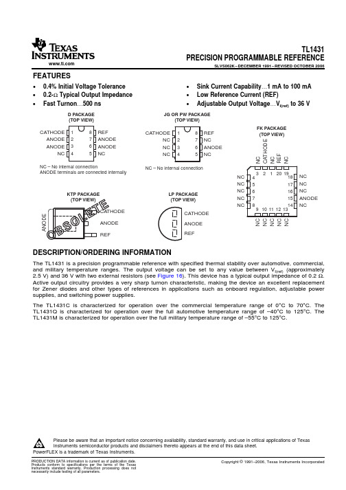
8 REF 7 ANODE 6 ANODE 5 NC
NC – No internal connection ANODE terminals are connected internally.
ANODE
KTP PACKAGE (TOP VIEW)
CATHODE
ANODE REF
TL1431 PRECISION PROGRAMMABLE REFERENCE
(2) All voltage values are with respect to ANODE, unless otherwise noted. (3) Maximum power dissipation is a function of TJ(max), θJA, and TA. The maximum allowable power dissipation at any allowable ambient
Please be aware that an important notice concerning availability, standard warranty, and use in critical applications of Texas Instruments semiconductor products and disclaimers thereto appears at the end of this data sheet.
Copyright © 1991–2006, Texas Instruments Incorporated
元器件交易网
TL1431 PRECISION PROGRAMMABLE REFERENCE
SLVS062K – DECEMBER 1991 – REVISED OCTOBER 2006
WFF4N60中文资料

102
Operation in This Area is Limited by R DS(on)
101
100 µs
1 ms
10 ms
100
DC
10-1 10-2
100
※ Notes :
1. TC = 25 oC 2. TJ = 150 oC 3. Single Pulse
101
102
IS
Continuous Source Current
Integral Reverse p-n Junction
ISM
Pulsed Source Current
Diode in the MOSFET
VSD
Diode Forward Voltage
IS =4.0A, VGS =0V
trr
Reverse Recovery Time
8
VDS = 480V
6
4
2
※ Note : ID = 4.0 A
0
0
4
8
12
16
20
QG, Total Gate Charge [nC]
Figure 6. Gate Charge Characteristics
元器件交易网
Typical Characteristics (Continued)
Symbol 1. Gate{
{ 2. Drain
●
◀▲
● ●
{ 3. Source
TO-220F
123
Absolute Maximum Ratings *( Drain current limited by junction temperature)
16244中文资料
CONTENTS
1. GENERAL INFORMATION
1.1 Product Overview
2
1.2 Part Numbering System
2
1.3 Absolute Maximum Ratings
3
1.4 Circuit Block Diagram
3
1.5 Mechanical Cha
tC tr tf tW tSU th tD tDH
Min.
500 ----220 40 10 --20
Typ.
-----------------
Max.
--25 25 ------120 ---
Unit
V
Supply current for logic
IDD
---
---
1.38
3
mA
0°C
---
5.10
---
V
Operating voltage for LCD*
VDD-VO
25°C
---
4.50
---
V
50°C
---
4.30
---
V
Input voltage ' H ' level Input voltage ' L ' level
3
1.6 Input Signal Function
4
1.7 LCM Contrast Control and Bias
4
1.8 LCD Dimensions
5
2. ELECTRICAL / OPTICAL CHARACTERISTICS
2.1 DC Electrical Characteristics
AOD414中文资料
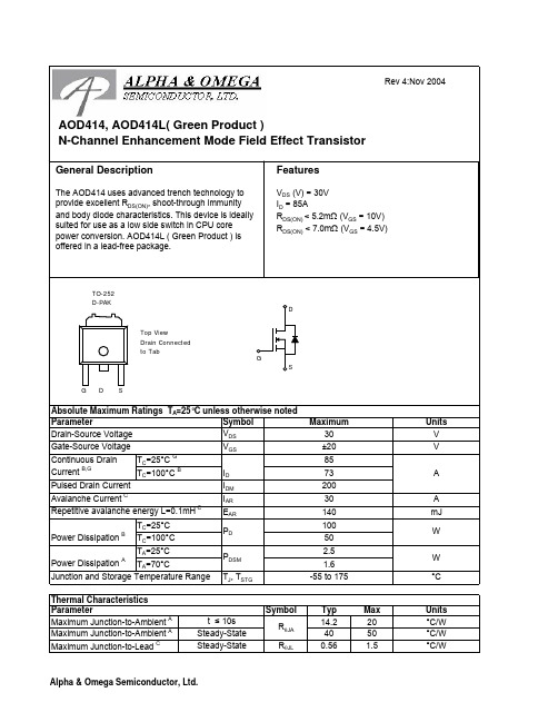
SymbolTyp Max 14.2204050R θJL 0.56 1.5°C/W Maximum Junction-to-Ambient ASteady-State Maximum Junction-to-Lead CSteady-State°C/WThermal Characteristics ParameterUnits Maximum Junction-to-Ambient At ≤ 10s R θJA °C/WSymbolMin TypMaxUnits BV DSS 30V 0.0051T J =55°C5I GSS 100nA V GS(th) 1.2 1.82.4V I D(ON)110A 4.2 5.2T J =125°C67.55.67m Ωg FS 85S V SD 0.71V I S85A C iss 60607000pF C oss 638pF C rss 355pF R g0.450.6ΩQ g (10V)96.4115nC Q g (4.5V)46.455nC Q gs 13.6nC Q gd 15.6nC t D(on)15.721ns t r 14.221ns t D(off)55.575ns t f 1421ns t rr 3138ns Q rr2429nCT C =100°C T A =25°C-55 to 175THIS PRODUCT HAS BEEN DESIGNED AND QUALIFIED FOR THE CONSUMER MARKET. APPLICATIONS OR USES AS CRITICAL COMPONENTS IN LIFE SUPPORT DEVICES OR SYSTEMS ARE NOT AUTHORIZED. AOS DOES NOT ASSUME ANY LIABILITY ARISING OUT OF SUCH APPLICATIONS OR USES OF ITS PRODUCTS. AOS RESERVES THE RIGHT TO IMPROVE PRODUCT DESIGN,FUNCTIONS AND RELIABILITY WITHOUT NOTICE.Gate Drain Charge V GS =0V, V DS =15V, f=1MHz SWITCHING PARAMETERS Total Gate Charge Gate Source Charge Gate resistanceV GS =0V, V DS =0V, f=1MHzTotal Gate Charge V GS =4.5V, V DS =15V, I D =20ATurn-On Rise Time Turn-Off DelayTime V GS =10V, V DS =15V, R L =0.75Ω, R GEN =3ΩTurn-Off Fall TimeTurn-On DelayTime m ΩV GS =4.5V, I D =20AI S =1A,V GS =0V V DS =5V, I D =20AMaximum Body-Diode Continuous CurrentInput Capacitance Output Capacitance DYNAMIC PARAMETERS R DS(ON)Static Drain-Source On-ResistanceForward TransconductanceDiode Forward VoltageI DSS µA Gate Threshold Voltage V DS =V GS I D =250µA V DS =24V, V GS =0VV DS =0V, V GS = ±20V Zero Gate Voltage Drain Current Gate-Body leakage current Electrical Characteristics (T J =25°C unless otherwise noted)STATIC PARAMETERS Parameter Conditions Body Diode Reverse Recovery Time Body Diode Reverse Recovery ChargeI F =20A, dI/dt=100A/µsDrain-Source Breakdown Voltage On state drain currentI D =250µA, V GS =0V V GS =4.5V, V DS =5V V GS =10V, I D =20AReverse Transfer Capacitance I F =20A, dI/dt=100A/µs A: The value of R θJA is measured with the device mounted on 1in 2 FR-4 board with 2oz. Copper, in a still air environment with T A =25°C. The Power dissipation P DSM is based on steady-state R θJA and the maximum allowed junction temperature of 150°C. The value in any a given application depends on the user's specific board design, and the maximum temperature fo 175°C may be used if the PCB or heatsink allows it.B. The power dissipation P D is based on T J(MAX)=175°C, using junction-to-case thermal resistance, and is more useful in setting the upper dissipation limit for cases where additional heatsinking is used. It is used to determine the current rating, when this rating falls below the package limit.C: Repetitive rating, pulse width limited by junction temperature T J(MAX)=175°C.D. The R θJA is the sum of the thermal impedence from junction to case R θJC and case to ambient.E. The static characteristics in Figures 1 to 6 are obtained using <300 µs pulses, duty cycle 0.5% max.F. These tests are performed with the device mounted on 1 in 2 FR-4 board with 2oz. Copper, in a still air environment with T A =25°C. The SOA curve provides a single pulse rating.G. The maximum current rating is limited by the package current capability.。
中微爱芯CS1621 32列4行LCD驱动控制电路产品说明书

江苏省无锡市滨湖区建筑西路777号无锡国家集成电路设计中心B4楼 第 1 页 共 27 页http://www.i-core. cn 邮编:214072版本:2019-07-A1CS162132列4行LCD 驱动控制电路产品说明书说明书发行履历:圳富瑞世嘉 中微爱芯一级代理(微信):13530167943 址:www.forchip.cn江苏省无锡市滨湖区建筑西路777号无锡国家集成电路设计中心B4楼第 2 页 共 27 页http://www.i-core. cn 邮编:214072版本:2019-07-A11、概 述CS1621是一种128点阵式存储映射多功能LCD 驱动电路。
CS1621的S/W 结构特点,使它适合点阵式LCD 显示,包括LCD 模块和显示子系统,CS1621还具有节电功能。
其主要特点如下: ● 工作电压:2.4V ~5.5V ● 内部256kHz RC 振荡器● 外部32kHz 晶振或256kHz 频率输入● 可选择1/2或1/3偏置和1/2、1/3或1/4占空比LCD 显示 ● 内部时基频率源● 蜂鸣器驱动信号频率可选择2kHz 或4kHz ● 具有关机指令可减少功耗● 内部时基发生器和WDT 看门狗定时器 ● 内部时基或WDT 溢出输出 ● 八个时基/WDT 时钟的时钟源 ● 32×4 LCD 驱动器 ● 内部32×4bit 显示RAM ● 四路串行接口 ● 内部LCD 驱动频率源 ● 可用指令控制操作 ● 数据模式和命令模式指令 ● R/W 地址自动累加 ● 三种数据访问模式● VLCD 引脚用来调整LCD 工作电压 ● 工作环境温度:-40~85℃● 封装形式:SOP16/SOP24/SSOP24/SOP28/QFP44/SSOP48/LQFP48深圳富瑞世嘉 中微爱芯一级代理手机(微信):13530167943网 址:www.forchip.cn江苏省无锡市滨湖区建筑西路777号无锡国家集成电路设计中心B4楼 第 3 页 共 27 页http://www.i-core. cn 邮编:214072版本:2019-07-A1订购信息: 管装:注:如实物与订购信息不一致,请以实物为准。
WF4M16-150DTM5A中文资料
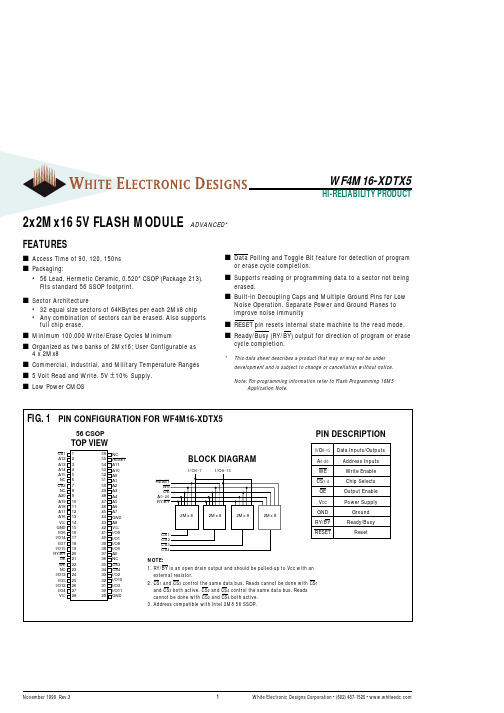
1White Electronic Designs Corporation • (602) 437-1520 • November 1999 Rev.32x2Mx16 5V FLASH MODULE ADVANCED*s Data Polling and Toggle Bit feature for detection of program or erase cycle completion.s Supports reading or programming data to a sector not being erased.s Built-in Decoupling Caps and Multiple Ground Pins for Low Noise Operation, Separate Power and Ground Planes to improve noise immunity s RESET pin resets internal state machine to the read mode.s cycle completion.*This data sheet describes a product that may or may not be under development and is subject to change or cancellation without notice.Note: For programming information refer to Flash Programming 16M5 Application Note.FEATURESs Access Time of 90, 120, 150ns s Packaging:•56 Lead, Hermetic Ceramic, 0.520" CSOP (Package 213).Fits standard 56 SSOP footprint.s Sector Architecture•32 equal size sectors of 64KBytes per each 2Mx8 chip •Any combination of sectors can be erased. Also supports full chip erase.s Minimum 100,000 Write/Erase Cycles Minimums Organized as two banks of 2Mx16; User Configurable as 4 x 2Mx8s Commercial, Industrial, and Military Temperature Ranges s 5 Volt Read and Write. 5V ± 10% Supply.s Low Power CMOS2White Electronic Designs Corporation • (602) 437-1520 • WF4M16-XDTX5ABSOLUTE MAXIMUM RATINGSParameterSymbol Ratings Unit Voltage on Any Pin Relative to V SS V T -2.0 to +7.0V Power Dissipation P T 8W Storage TemperatureTstg -65 to +125°C Short Circuit Output Current I OS100mA Endurance - Write/Erase Cycles 100,000 mincycles (Mil Temp)Data Retention (Mil Temp)20yearsRECOMMENDED DC OPERATING CONDITIONSParameter Symbol Min Max Unit Supply Voltage V CC 4.5 5.5V GroundV SS 00V Input High Voltage V IH 2.0V CC + 0.5V Input Low VoltageV IL -0.5+0.8V Operating Temperature (Mil.)T A -55+125°C Operating Temperature (Ind.)T A-40+85°CDC CHARACTERISTICS - CMOS COMPATIBLE(V CC = 5.0V, V SS = 0V, T A = -55°C to +125°C)NOTES:1.The Icc current listed includes both the DC operating current and the frequency dependent component (@ 5MHz). The frequency component typically is less than IH .2.Icc active while Embedded Algorithm (program or erase) is in progress.3.DC test conditions V IL = 0.3V, V IH = V CC - 0.3VParameterSymbol ConditionsMinMax Unit Input Leakage Current I LI V CC = 5.5, V IN = GND to V CC 10µA Output Leakage Current I LOx32V CC = 5.5, V IN = GND to V CC10µA V CC Active Current for Read (1)I CC1CS = V IL , OE = V IH , f = 5MHz, V CC = 5.582mA V CC Active Current for Program or Erase (2)I CC2CS = V IL , OE = V IH , V CC = 5.5122mA V CC Standby Current I CC3V CC = 5.5, CS = V IH , f = 5MHz 8.0mA Output Low Voltage V OL I OL = 12.0 mA, V CC = 4.50.45V Output High Voltage V OH I OH = -2.5 mA, V CC = 4.50.85xVccV Low V CC Lock-Out VoltageV LKO3.24.2VCAPACITANCE (T A = +25°C)Parameter Symbol Conditions Max Unit OE capacitance C OE V IN = 0 V, f = 1.0 MHz 45pF WE capacitance C WE V IN = 0 V, f = 1.0 MHz 45pF CS capacitance C CS V IN = 0 V, f = 1.0 MHz 15pF Data I/O capacitance C I/O V I/O = 0 V, f = 1.0 MHz 25pF Address input capacitanceC ADV IN = 0 V, f = 1.0 MHz45pFThis parameter is guaranteed by design but not tested.3White Electronic Designs Corporation • (602) 437-1520 • 4White Electronic Designs Corporation • (602) 437-1520 • WF4M16-XDTX5AC CHARACTERISTICS – WRITE/ERASE/PROGRAM OPERATIONS,CS CONTROLLED(V CC = 5.0V, V SS = 0V, T A = -55°C to +125°C)Parameter Symbol-90-120-150UnitMinMaxMin MaxMin MaxWrite Cycle Time t AVAV t WC 90120150ns Write Enable Setup Time t WLEL t WS 000ns Chip Select Pulse Width t ELEH t CP 455050ns Address Setup Time t AVEL t AS 000ns Data Setup Time t DVEH t DS 455050ns Data Hold Time t EHDX t DH 000ns Address Hold Timet ELAX t AH 455050ns Chip Select Pulse Width Hight EHEL t CPH202020ns Duration of Byte Programming Operation (1)t WHWH1300300300µs Sector Erase Time (2)t WHWH2151515sec Read Recovery Time t GHELµs Chip Programming Time 444444sec Chip Erase Time (3)256256256sec Output Enable Hold Time (4)t OEH101010ns NOTES:1. Typical value for t WHWH1 is 7µs.2. Typical value for t WHWH2 is 1sec.3. Typical value for Chip Erase Time is 32sec.4. For Toggle and Data Polling.5White Electronic Designs Corporation • (602) 437-1520 • 6White Electronic Designs Corporation • (602) 437-1520 • 7White Electronic Designs Corporation • (602) 437-1520 • 8White Electronic Designs Corporation • (602) 437-1520 • 9White Electronic Designs Corporation • (602) 437-1520 • 10 White Electronic Designs Corporation • (602) 437-1520 • 元器件交易网11White Electronic Designs Corporation • (602) 437-1520 • 。
北京联盛德微电子有限责任公司W600芯片规格书说明书
W600芯片规格书V1.0.4北京联盛德微电子有限责任公司 (Winner Micro)地址:北京市海淀区阜成路67号银都大厦18层电话:+86-10-62161900网址:文档历史目录1特征 (1)2概述 (4)3芯片特点 (4)4芯片结构 (4)5地址空间划分 (5)6功能描述 (6)6.1SDIO设备控制器 (6)6.2高速SPI设备控制器 (6)6.3DMA控制器 (6)6.4时钟与复位 (7)6.5内存管理器 (7)6.6数字基带 (7)6.7MAC控制器 (7)6.8安全系统 (8)6.9FLASH控制器 (8)6.10RSA加密模块 (8)6.11通用硬件加密模块 (8)6.12I2C控制器 (8)6.13主/从SPI控制器 (8)6.14UART控制器 (9)6.15GPIO控制器 (9)6.16定时器 (9)6.17看门狗控制器 (9)6.18射频配置器 (9)6.19射频收发器 (10)6.20PWM控制器 (10)6.21I²S控制器 (10)6.227816/UART控制器 (10)7管脚定义 (12)8电气特性 (14)8.1极限参数 (14)8.2射频功耗参数 (14)8.3Wi-Fi射频 (14)9封装信息 (16)10产品型号定义 (17)1特征⚫芯片外观➢QFN32封装,5mm x 5mm⚫芯片集成度➢集成32位嵌入式Cortex-M3处理器,工作频率80MHz;➢集成288KB数据存储器;➢集成1MB/2MB FLASH;➢集成8通道DMA控制器,支持任意通道分配给硬件使用或是软件使用,支持16个硬件申请,支持软件链表管理;➢集成2.4G射频收发器,满足IEEE802.11规范;➢集成PA/LNA/TR-Switch;➢集成32.768KHz时钟振荡器;➢集成电压检测电路;➢集成LDO;➢集成电源控制电路;➢集成上电复位电路;➢集成通用加密硬件加速器,支持PRNG/SHA1/MD5/RC4/DES/3DES/AES/CRC/RSA等多种加解密协议。
上门维修必备的常用元器件
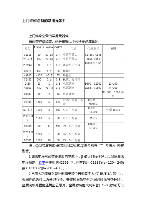
上门维修必备的常用元器件上门维修必备的常用元器件晶体管种类如表。
这是根据以下代换要点准备的。
注:①型号后有(D)者带阻尼二极管;②型号前有“*”号者为PNP 型管。
1.调谐电压形成管要求反向电流小,β值大且线性好,以保证调谐电压稳定。
彩电中多用PH2369型,也有的用C1815Y(β=120~240)或C1815GR(β=200~400)。
2.常用大功率塑封管外形和安装位置相差不大(仅BUTl1A较小),相同性能的可以方便地互换。
安装时与散热片之间必须涂导热硅脂,金属底板外露的还需垫云母片。
金属封装的大功率管(TO-3封装)可以用性能相当的塑封管代换。
表1中未列入。
3.更换电源开关管或调宽管后如果有开关管过热、不易启动、吱吱叫、+B波动大等现象,应考虑新件β值低或饱和压降大的可能。
调宽管必须选饱和压降低。
且β>100的。
没有条件进行实际测试时,可选用标称反向电压较低(BVcbo=20~30V)、Icm≥lA的中功率管。
由于生产工艺的特点。
BVcbo高的晶体管的饱和压降Vces一般较大,故不宜选用。
换行输出管后也应检查其散热片温升和行电流。
4.晶体管宜选用原装进口件,虽然价格贵些,但性能好,可j靠性高,比如大功率管的B值线性好,即大电流下β下降不多。
有些拆机件也是不错的。
如笔者邮购的BU2527AX和BU2527DX 管,均为1500V、12A、125W,可以分别作为电源开关{管和行输出管,用于21~29英寸彩电。
1.开关二极管1N4148(75WO.15A)。
2.整流二极管1N4007(1A/1000V)、1N5404(3A/400V),多用于市电整流桥堆损坏后的代换。
3.快恢复二极管FRl07(1A/700V)、FR207(2A/700V)、FR307(3A700V),用于开关电源、行逆程电源等高频整流电路中。
4.稳压二极管选工作电压如下的几种(功率均为1W):2.7V、5.1V、5.6V、6.2V、7.5V、8.2V、9.1V、12V。
飞利浦 ACR4164BF 直流无叶风扇 使用说明书

ACR4164BF
8注意事项
4
•
••••
••
•
•
•
•••
风扇应按额定电压使用,切不可接在其他种类的电源上使用。
使用风扇时,切勿把手指或其它物件伸入网罩内。
勿用湿手拔电源插头,避免感电、触电的危险。
若移动风扇位置、清洁风扇及人离开时请拔掉电源插头。
勿将风扇放置在倾斜地面,避免风扇翻倒。
严禁对着火炉或瓦斯吹。
如果电源软线损坏,为了避免危险,必须由制造商其维修部或类似部门的专业人员更换。
运输、安装及贮藏中,注意不要碰撞及挤压风扇,以免影响风扇的性能。
使用中如出现异常噪声、气味、烟雾等现象,应立即切断电源,并送本公司售后服务部检修。
请避开高温、高湿度、酸碱油、杀虫水及窗帘等易吸进物品使用。
勿对婴孩、病人、老人长时间直接吹风。
在无成年人看守的情况下严禁使用本产品。
请不要用手强行旋转扇体,以免损坏摇头电机。
••
•
清洁维护风扇时,请拔出电源插头,禁止带电操作。
风扇电流过大安全保护:在风扇电机内安装有一只过流保护器,当电机因各种意外引起电流过大时,过流保护器动作,切断电机电源。
警告: 拆下防护外壳前必须确保电扇与电源断开。
产品保修卡。
武藤VJ-1604W中文菜单之欧阳与创编
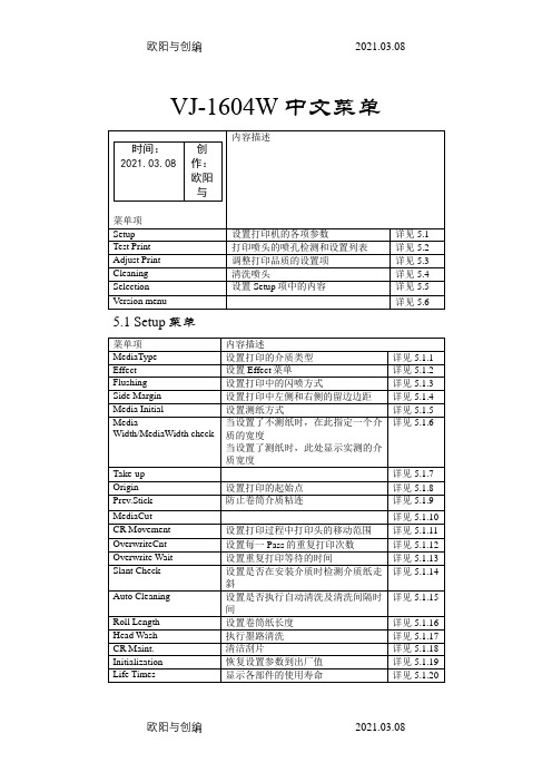
VJ-1604W中文菜单5.1 Setup菜单5.1.1 MediaType 菜单5.1.1.1 Type菜单5.1.1.1.2 PF Adjust菜单(1) Init.Adj.Print菜单执行初始步进打印(2) Init.Adj.Change菜单设置初始步进更改(3) Confirm Print菜单执行确认打印(4) Micro Adj.Print菜单执行微调打印(5) Micro Adj.Change菜单设置步进微调更改5.1.1.1.7 Vacuum Fan菜单设置吸纸风扇的操作5.1.2 Effect菜单设置打印效果菜单当需要提高打印质量时,设置此菜单5.1.3 Flushing菜单设置打印中的闪喷操作5.1.3.1 Flushing return count菜单设置当闪喷方式被设置为“On Media”时,喷头回到原点的闪喷墨栈闪喷的频率(闪喷计数)5.1.4 Side Margin菜单设置打印时左、右页边距的空白(页边距)5.1.5 Media Initial菜单设置当介质初始化时,介质的宽度和边缘被检测的方式5.1.6Media Width/MediaWidth菜单当介质初始化设置为不检测介质时,设置从右边5mm 到左边的距离(1)Media Width菜单当介质初始化完成介质检测时,显示被检测到的介质宽度(2)MediaWidth菜单5.1.7Take-up菜单5.1.8Origin菜单设置打印时的开始打印位置(原点)当需要在打印过的介质的页边距空白处再次打印时,设置此项5.1.9 Prev.Stick菜单防止打印过程中出现粘连现象5.1.10Media Cut菜单5.1.11CR Movement菜单设置打印过程中,喷头移动的范围5.1.12 Overwrite菜单设置重复打印计数5.1.13Overwrite Wait菜单设置重复打印等待时间5.1.14Slant Check菜单设置进纸时纸走斜检测5.1.15 Auto Cleaning菜单设置这台机器自动清洗的间隔时间为防止喷头阻塞,开机后即执行自动清洗操作5.1.16 Roll Length菜单设置卷筒介质长度5.1.16.1 Roll Length菜单设置卷筒介质长度5.1.17Head Wash菜单执行墨路清洗5.1.18CR Maintenance菜单清洁刮片5.1.19 Initialization菜单使打印机的设置值恢复默认值5.1.20 Life Times菜单显示各部件的运行寿命5.1.21IPAddress菜单设置打印机的IP地址5.1.22Subnet Mask菜单设置打印机的子网掩码5.1.23 Gateway菜单设置网关5.2 TestPrint菜单执行喷头的喷孔检测及设置清单打印5.3Adjust Print菜单当需要为图片打印调整为最适宜品质时设置5.4 Cleaning菜单执行喷头清洗5.5 Selection菜单设置“Setup”的内容在打印机的正常使用情况下,你可以隐藏你不想改变设置值的设置菜单中的设置项5.6 Version menu菜单。
SONY-A45用户手册
型号名称
此[帮助指南]中出现了几个型号名称。取决于您购买Walkman的国家或地区,可能没有某些机型。
电脑系统要求
当您连接Walkman到电脑时,请检查电脑的系统要求。
电池充电
首次使用Walkman时,电池电量可能较低。使用之前请给电池充电。
microSD卡
帮助指南
数码音频播放器
NW-A45/A45HN/A46HN/A47
安装线夹
(仅限提供线夹的型号) 如下图所示将线夹安装到耳机上。您可将线夹夹到衣服或背包上。使用线夹可能可以减少耳机线与衣服摩擦产生的噪音。
帮助指南的内容可能会因产品规格的更新而在没有通知的情况下变更。
相关主题 检查包装的内容
4-698-301-72(1) Copyright 2017 Sony Corporation
安装Music Center for PC(Windows)
Music Center for PC是个用于Windows电脑的应用程序。请使用最新版本的Music Center for PC。 您可以使用Music Center for PC进行以下操作。
从CD导入内容(例如音乐)到电脑。 组织和管理内容。 例如,您可以建立播放列表。 传送电脑上的内容到Walkman。 在安装Music Center for PC之前,请确认系统要求。 1 访问Music Center for PC下载网站。
10
帮助指南
数码音频播放器
NW-A45/A45HN/A46HN/A47
切换耳塞
(仅限提供耳塞的机型) 为享受更好的音质,请选择适合每只耳朵大小的耳塞。
1 从耳机取下耳塞。 抓住耳机,然后扭动并拉出耳塞。 如果耳塞很滑,请用软干布包住它们。
- 1、下载文档前请自行甄别文档内容的完整性,平台不提供额外的编辑、内容补充、找答案等附加服务。
- 2、"仅部分预览"的文档,不可在线预览部分如存在完整性等问题,可反馈申请退款(可完整预览的文档不适用该条件!)。
- 3、如文档侵犯您的权益,请联系客服反馈,我们会尽快为您处理(人工客服工作时间:9:00-18:30)。
gY< XHH
J HF
. 5 ./
J J
LQ%)4) LQ%)4) Ω LQ
HS%M+>(+L%&7%9%,+>">("=+;T%09(8$+L%/@%Ω (& ./%Ω "0)+L978+%(,97>G&,0+,S
.
N#+,+%XT>(+0>%Y78S
3/:/&;<--:=&>-?@&" A8?-*.-0&B(("
@SHb@%c%@S@? `/S@%c%@S6a
@S@C6 `.S@a
@SC@@%c%@S@? `H6S@%c%@S6a
@S?F/ `bS?a @S.H/%c%@S@H `/S/%c%@S./a @S@5@ `HS@a
@S.56 `FS?a
H4HHCbS`Pa
K+)&S)P80*/:+8)
N/.1-&'@&K+)&3-2D0+C:+8)2 K+)&A8@ H . ? 5 / F C 6 b H@ HH H. H? H5 N#+,+%XT>(+0>%Y78S 3-2D0+C:+8) M$+,0">(&, M$+,0">(&, L8%K9>+,%Q"9>%`Ua D\O%N7&L+-%39>+%h,&'7L D\O%39($&L+ M$+,0&+;+8(,"8%3&&;+,%`Wa M$+,0&+;+8(,"8%3&&;+,%`Ua 39>+%h,&'7L 39>+%h,&'7L <3 K9>+,%3&00&7%`Wa K9>+,%D&L';9("&7%`Ua K9>+,%3&00&7%`Wa <3 /
!CC1+D/:+8)2
s
H?H@%70%*",+;+>>I J%K&7#%L">(978+> J%!"#$48&'7(%&)("89;%>);"(>
/
!"#"$%&"'"(&)*&%+,-./),&%+0-1-22&345&6/2-0&78,91-2
3/:/&;<--:=&>-?@&" A8?-*.-0&B(("
D\3%3NM!2O[
M[3%`Wa
F @S@H%µP
M[3%`Ua
C
@S@H%µP
H4H.?6PS8
<&(+I%1$+7%&,L+,"7#%($+%L8%>+(-%($+%G&;;&*"7#%:&9,L>%9,+%"78;'L+LI%9;9,0%:&9,L-%bH@64@@5j%M[3%:&9,L-%b@.64@@5j%8&7>(97(%8',,+7(-%b?6?4@@5S
!"#"$%&"'"(&)*&%+,-./),&%+0-1-22&345&6/2-0&78,91-2
G1-D:0+D/1&;D<-*/:+D2&
H YX2KNM2^ .
<3
H5
H?
`Wa
5
HH
`Wa
`Wa
/
<3 3NX[ h^2i<O 3NX[ h^2i<O
H@
`Wa
F
b
`Ua
C
M[3
G1-D:0+D/1HIC:+D/1&J</0/D:-0+2:+D2
N/.1-&"@&G1-D:0+D/1&/),&IC:+D/1&J</0/D:-0+2:+D2 K/0/*-:-0 19=+;+7#($% 2)("89;%2'()'(%\&*+,%H 2)("89;%Y>&;9("&7 X"L+%D&L+%X')),+>>"&7%^9("& M$,+>$&;L%3',,+7( 2)+,9("7#%3',,+7( D&7"(&,%\O%3',,+7( M$+,0">(&,%^+>">(978+ M$+,0">(&,%M+0)+,9(',+%3&+GG"4 8"+7( M[3%3',,+7( ;L*.81 λ2\ \2 YX2 XDX^ YM! Y2\ Y\O ^M! M3M! YM[3 J8),+:+8)& YP%]%Y2\-%M%]%M2\ YP%]%Y2\ %M2\%]%./%V3 YP%]%Y2\ ./%V3-%Q2K Q2K _^D%]%/%_M2\%]%./%V3 %M2\%]%./%V3 %M2\%]%./%V3 U5@%°3%<%M3%< +6/%°3M2\%]%./%V3YP%]%H@@%0N 7+) J 5 ?@ ?@ F YM!%W%H@ H@ J J J NLC H?H@%c%H@ J J J HH J J H@%c%@S/%9(%./%V3 U5S5%9(%./%V3 J 7/E J ./ J J ?@ H@@ .@@ J J HSF M)+: 70 01 LQ LQ 0N 0N µNd01 AΩ edV3 N
!"#"$%&"'"(&)*&%+,-./),&%+0-1-22&345&6/2-0&78,91-2
3/:/&;<--:=&>-?@&" A8?-*.-0&B(("
6/2-0&;/P-:L&S)P80*/:+8)
J1/22&SSS.&6/2-0&K08,9D:
PONd3O^!%3;9>>%YYY:%;9>+,%),&L'8(S%N;;%=+,>"&7>%9,+%3;9>>%YYY:%;9>+,%),&L'8(>%)+,%3O^!-%.H%3P^%H@5@%K9>+,% X9G+(T%,+R'",+0+7(>S%N;;%=+,>"&7>%9,+%3;9>>%?Q%;9>+,%),&L'8(>%)+,%012*o%F@6./4HIHbb?S%M$+%L+="8+%$9>%:++7%8;9>4 >"G"+L%*"($%($+%PON%'7L+,%97%988+>>"&7%7'0:+,%(&%:+%L+(+,0"7+LS M$">%),&L'8(%8&0);"+>%*"($%.H%3P^%H@5@SH@%97L%H@5@SHHS X"7#;+40&L+%G":+,%)"#(9";% 19=+;+7#($%]%H?H@%70 D9Z"0'0%)&*+,%]%/@%01 Q+89'>+%&G%>"B+%8&7>(,9"7(>-%;9>+,%>9G+(T%;9:+;"7#%`"78;'L"7#%97%PON%3;9>>%YYY:%;9:+;a%">%7&(%9GG"Z+L%(&%($+%0&L';+%:'(% 9((98$+L%(&%($+%&'(>"L+%&G%($+%>$"))"7#%89,(&7S \,&L'8(%">%7&(%>$"))+L%*"($%)&*+,%>'));TS J/9:+8)T%M2-&8P&D8):0812=&/,U92:*-):2=&/),&C08D-,90-2&8:<-0&:</)&:<82-&2C-D+P+-,&<-0-+)&*/L&0-291:&+)& </V/0,892&1/2-0&0/,+/:+8)&-EC8290-@
