BZX55C27中文资料
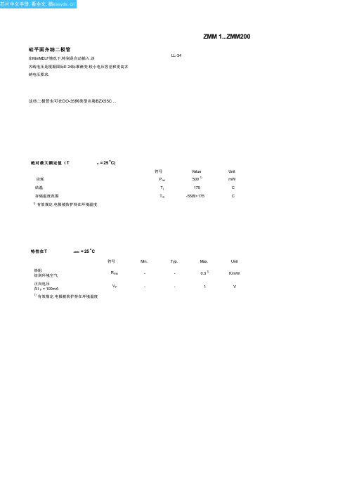
ZMM5V1中文资料(Shenzhen Jin)中文数据手册「EasyDatasheet - 矽搜」
60
70
80
90
100 V
Vz
正向特性
mA 10
10 i
10
1
10
10
10
10 10
0
ZMM...
Tj=100 C Tj=25 C
0.2
0.4
0.6
0.8
1V
V
容许功耗 随环境温度 Valid provided that electrodes are kept at ambient temperature.
1
ZMM 2V2
2.2
5
2.08...2.33
1
ZMM 2V4
2.4
5
2.28...2.56
1
ZMM 2V7
2.7
5
2.5...2.9
1
ZMM 3V0
3.0
5
2.8...3.2
1
ZMM 3V3
3.3
5
3.1...3.5
1
ZMM 3V6
3.6
5
3.4...3.8
1
ZMM 3V9
3.9
5
3.7...4.1
Capacitance versus Zener voltage
Dynamic resistance versus Zener current
75
2.5
70...79
0.5
ZMM 82
82
2.5
77...87
0.25
ZMM 91
91
1
85...96
0.1
ZMM 100
100
1
94...106
0.1
ZMM 110
SMC 55-CQ2-Z Series II 2GD 轨迹遥控器说明书
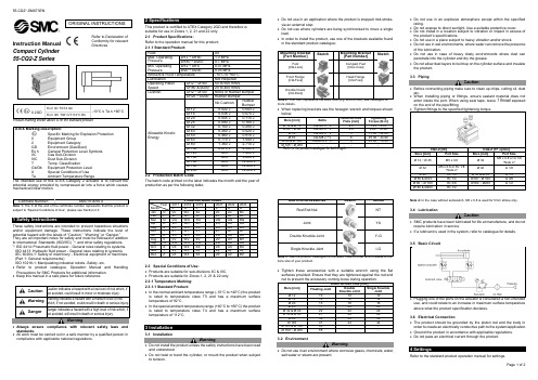
Instruction ManualCompact Cylinder 55-CQ2-Z SeriesProduct marking shown above is for the standard product.II 2potential energy provided by compressed air into a force which causes mechanical linear motion. subject to “Special Conditions of Use”, please see Section 2.3.1 Safety InstructionsThese safety instructions are intended to prevent hazardous situations and/or equipment damage. These instructions indicate the level of potential hazard with the labels of “Caution,” “Warning” or “Danger.” They are all important notes for safety and must be followed in addition to International Standards (ISO/IEC) *1), and other safety regulations. *1)ISO 4414: Pneumatic fluid power - General rules relating to systems. ISO 4413: Hydraulic fluid power - General rules relating to systems.IEC 60204-1: Safety of machinery - Electrical equipment of machines. (Part 1: General requirements)ISO 10218-1: Manipulating industrial robots -Safety. etc.∙ Refer to product catalogue, Operation Manual and Handling Precautions for SMC Products for additional information. ∙ Keep this manual in a safe place for future reference.not avoided, will result in death or serious injury.Warning∙ Always ensure compliance with relevant safety laws and standards.∙ All work must be carried out in a safe manner by a qualified person in compliance with applicable national regulations.2 SpecificationsThis product is certified to ATEX Category 2GD and therefore is suitable for use in Zones 1, 2, 21 and 22 only. 2.1 Product Specifications:Refer to the operation manual for this product;The batch code printed on the label indicates the month and the year of production as per the following table;2.3 Special Conditions of Use:∙ Products are suitable for sub-divisions IIC & IIIC. ∙ Products are suitable for Zones 1, 2, 21 & 22 only. 2.3.1 Temperature Marking: 2.3.1.1 Standard Product:∙ In the normal ambient temperature range (-10°C to +40°C) the product is rated to temperature class T5 and has a maximum surface temperature of 92°C.∙ In the special ambient temperature range (+40°C to +60°C) the product is rated to temperature class T4 and has a maximum surface temperature of 112°C.3 Installation3.1 InstallationWarning∙ Do not install the product unless the safety instructions have been read and understood.∙ Do not twist or bend the cylinder, or mount the product when subject to tension.∙ Do not use in an application where the product is stopped mid-stroke, via an external stop.∙ Do not use where cylinders are being synchronised to move a single load.∙ In order to install the product, use one of the brackets available found in the standard product catalogue;represents the Bore Size (e.g. Ø40 is 040), see catalogue for more details.∙ When replacing brackets use the hexagon wrench and torques shownSketchSee the product catalogue for the exact code to order which relates to the bore size of your product.∙ Tighten these accessories with a suitable wrench using the flat surfaces provided. Ensure that they are tightened against the rod end 3.2 EnvironmentWarning∙ Do not use in an environment where corrosive gases, chemicals, water, salt water or steam are present.∙ Do not use in an explosive atmosphere except within the specified rating.∙ Do not expose to direct sunlight. Use a suitable protective cover.∙ Do not install in a location subject to vibration or impact in excess of the product’s specifications .∙ Do not use in a place subject to heavy vibration and/or shock.∙ Do not use in wet environments, where water can remove the presence of the lubrication.∙ Do not use in case of heavy dusty environments where dust can penetrate into the cylinder and dry the grease.∙ Do not allow dust layers to build up on the cylinder surface and insulate the product.3.3 PipingCaution∙ Before connecting piping make sure to clean up chips, cutting oil, dust etc.∙ When installing piping or fittings, ensure sealant material does not enter inside the port. When using seal tape, leave 1 thread exposed on the end of the pipe/fitting.∙ Tighten fittings to the specified tightening torque.CQ2-Z [Nil]CQ2-Z [TF option]Note 4: In the case without autoswitch, M5 x 0.8 is used for 5mm stroke only.3.4 LubricationCaution∙ SMC products have been lubricated for life at manufacture, and do not require lubrication in service.∙ If a lubricant is used in the system, refer to catalogue for details.3.5 Basic Circuit∙ Plugging one of the ports on the actuator is considered a non-intended use, and could relate to an increase in maximum surface temperature above what the product specification declares.3.6 Electrical Connection∙ The product should be grounded by the piston rod and the body in order to create an electrically conductive path to the system/application. ∙ Ground the product in accordance with applicable regulations. ∙ Do not pass an electrical current through the product.4 SettingsRefer to the standard product operation manual for settings.ORIGINAL INSTRUCTIONSRefer to Declaration of Conformity for relevant DirectivesRefer to the standard product catalogue for ‘How to Order’. Refer to the standard product catalogue for general dimensions.7.1 General MaintenanceCaution∙Not following proper maintenance procedures could cause the product to malfunction and lead to equipment damage.∙If handled improperly, compressed air can be dangerous.∙Maintenance of pneumatic systems should be performed only by qualified personnel.∙Before performing maintenance, turn off the power supply and be sureto cut off the supply pressure. Confirm that the air is released to atmosphere.∙After installation and maintenance, apply operating pressure and power to the equipment and perform appropriate functional and leakage tests to make sure the equipment is installed correctly.∙If any electrical connections are disturbed during maintenance, ensure they are reconnected correctly and safety checks are carried out as required to ensure continued compliance with applicable national regulations.∙Do not make any modification to the product.∙Do not disassemble the product, unless required by installation or maintenance instructions.∙Do not use a product which looks or contains damage, this will invalidate the certification. If damage is seen, please replace the product immediately.∙Periodically check the product for any damage or rust appearing. This could result in an increase in friction and lead to dangerous conditions. Replace the whole actuator if any of these conditions appear.∙Periodically check the condition of the rod seal and for the presence of lubrication, where possible. If these areas appear to be dry, please follow the lubrication procedure.∙Replace the seals, when air leakage is above the allowable value given in the table below;7.2 Disassembly Procedure∙Disassemble the cylinder, remove the old grease and place all the parts on a clean cloth in a clean environment. Use a set of snap ring pliers to remove the snap ring. Remove the old tube gaskets, rod seal, piston seal, wear ring using a fine screwdriver where necessary.Caution∙If a magnet is present on the piston do not remove it. The magnet is not replaceable.7.2.1 Model: C(D)Q2* 12~100(TF)-*D(C)(M)Z7.2.2 Models: C(D)Q2B 125~200(TF)-*DC(M)Z, C(D)Q2* 32~100(TF)-7.2.3 Model: C(D)Q2W* 12~200(TF)-*D(C)(M)Z / Double Rod type7.2.4 Model: C(D)Q2BS 32~100(TF)-*DC(M) / Anti-Lateral Load type7.3 Seal Replacement Part NumbersWarningOnly use SMC seal kits as listed in the table below;7.4 Lubrication Procedure∙Apply lubricant to:• The rod seal and the rod seal groove on the rod cover.• The piston outer surface and piston seal groove.• The piston seal and tube gaskets.• The piston rod surface and cylinder tube internal surface.∙Lubricate the parts with the grease packs provided with the seal kit.7.5 Reassembly Procedure∙Inserting the collar assembly into the piston rod assembly.Apply grease to the end of the piston rod, especially on the 30° chamferand on the flats. Insert with care the piston rod into the collar assemblyto prevent any damage to the rod seal.∙Inserting piston rod assembly and collar assembly into the cylindertube.Insert slowly with care the piston assembly and the collar assembly intothe cylinder tube to prevent any damage of the piston seal and tubegasket.∙Installing snap ring.Use appropriate pliers (tool for C-shape snap ring) for installation.CautionWhen installing the snap ring, be aware that the snap ring may come offthe pliers and could result in operator injury or equipment damage. Alsomake sure ring is firmly seated in ring groove.∙Checking assembly.Make sure that no air is leaking from packing seals and that the cylinderoperates smoothly at minimum operating pressure. Check for cylindersmooth movement and for air leakage.8 Limitations of Use8.1 Limited warranty and Disclaimer/Compliance RequirementsRefer to Handling Precautions for SMC Products located on .8.2 Obligations of the end-user∙Ensure the product is used within the specification outlined.∙Ensure that the maintenance periods are suitable for the application.∙Ensure any cleaning processes to remove dust layers are made withthe atmosphere in mind (e.g. using a damp cloth to avoid static buildup).∙Ensure that the application does not introduce additional hazards bymounting, loading, impacts or other methods.∙Ensure that there is sufficient ventilation and air circulation around theproduct.∙If the product is subject to direct heat sources in the application, theyshould be shielded so that the actuator temperature stays within thestated operating range.Caution∙SMC products are not intended for use as instruments for legalmetrology.Measurement instruments that SMC manufactures or sells have notbeen qualified by type approval tests relevant to the metrology(measurement) laws of each country.Danger∙Do not exceed any of the specifications listed in Section 2 of thisdocument as this will be deemed improper use.∙Air equipment has an air leakage during operation within certain limits.Do not use this equipment when the air itself introduces additionalhazards and could lead to an explosion.∙Use only ATEX certified auto switches. These should be orderedseparately.∙Do not use this product in the presence of strong magnetic fields thatcould generate a surface temperature higher than the productspecification.∙Avoid applications where the piston rod end and the adjoining part inthe application can create a possible ignition source.∙Do not install or use these actuators where there is the possibility forthe piston rod to impact foreign objects.∙In the event of damage or failure of any parts located in the vicinitywhere this product has been installed, it is the responsibility of the userto determine whether or not this has compromised the safety andcondition of this product and/or the application.∙External impact on the cylinder body could result in a spark and/orcylinder damage. Avoid any application where foreign objects can hitor impact the cylinder. In such situations the application should installa suitable guard to prevent this occurrence.∙Do not use this equipment where vibration could lead to failure.9 ContactsRefer to Declaration of Conformity and for contacts.URL : http// (Global) http// (Europe)'SMC Corporation, Akihabara UDX15F, 4-14-1, Sotokanda, Chiyoda-ku, Tokyo 1010021Specifications are subject to change without prior notice from the manufacturer.© 2018 SMC Corporation All Rights Reserved.Template DKP50047-F-085H。
BZM55C20V资料
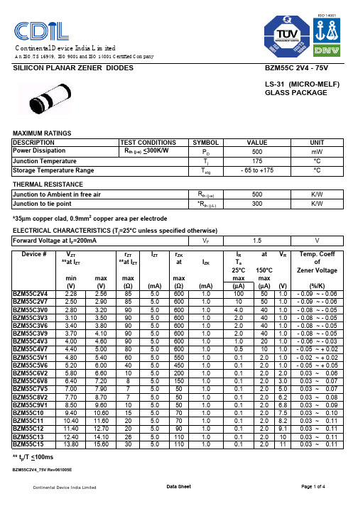
SILIICON PLANAR ZENER DIODES BZM55C 2V4 - 75V LS-31 (MICRO-MELF) GLASS PACKAGETHERMAL RESISTANCEJunction to Ambient in free air R th (j-a)Junction to tie point*R th (j-L)*35µm copper clad, 0.9mm 2copper area per electrodeELECTRICAL CHARACTERISTICS (T j =25°C unless specified otherwise)Forward Voltage at I F =200mA V F Device #V ZT r ZT I ZTr ZK I R at V R**at I ZT **at I ZT at I ZKT a 25°C 150°C min max max max max max (V)(V)(Ω)(mA)(Ω)(mA)(µA)(µA)(V)BZM55C2V4 2.28 2.5685 5.0600 1.010050 1.0BZM55C2V7 2.50 2.9085 5.0600 1.01050 1.0BZM55C3V0 2.80 3.2090 5.0600 1.0 4.040 1.0BZM55C3V3 3.10 3.5090 5.0600 1.0 2.040 1.0BZM55C3V6 3.40 3.8090 5.0600 1.0 2.040 1.0BZM55C3V9 3.70 4.1090 5.0600 1.0 2.040 1.0BZM55C4V3 4.00 4.6090 5.0600 1.0 1.020 1.0BZM55C4V7 4.40 5.0080 5.0600 1.00.510 1.0BZM55C5V1 4.80 5.4060 5.0550 1.00.1 2.0 1.0BZM55C5V6 5.20 6.0040 5.0450 1.00.1 2.0 1.0BZM55C6V2 5.80 6.6010 5.0200 1.00.1 2.0 2.0BZM55C6V8 6.407.208 5.0150 1.00.1 2.0 3.0BZM55C7V57.007.907 5.050 1.00.1 2.0 5.0BZM55C8V27.708.707 5.050 1.00.1 2.0 6.2BZM55C9V18.509.6010 5.050 1.00.1 2.0 6.8BZM55C109.4010.6015 5.070 1.00.1 2.07.5BZM55C1110.4011.6020 5.070 1.00.1 2.08.2BZM55C1211.4012.7020 5.090 1.00.1 2.09.1BZM55C1312.4014.1026 5.0110 1.00.1 2.010BZM55C1513.8015.60305.01101.00.12.011** t p /T <100msBZM55C2V4_75V Rev061005E500Zener Voltage 0.03 ~ 0.07 0.03 ~ 0.11of1.5V Temp. Coeff0.03 ~ 0.11(%/K)- 0.05 ~ + 0.02- 0.02 ~ + 0.02- 0.05 ~ + 0.05 0.03 ~ 0.06 0.03 ~ 0.07 0.03 ~ 0.09 0.03 ~ 0.10K/W 300K/W0.03 ~ 0.11 0.03 ~ 0.11 0.03 ~ 0.08- 0.09 ~ - 0.06- 0.09 ~ - 0.06- 0.08 ~ - 0.05- 0.08 ~ - 0.05- 0.08 ~ - 0.05- 0.08 ~ - 0.05- 0.06 ~ - 0.03Continental Device India LimitedAn ISO/TS 16949, ISO 9001 and ISO 14001 Certified CompanySILIICON PLANAR ZENER DIODESBZM55C 2V4 - 75V LS-31 (MICRO-MELF) GLASS PACKAGEELECTRICAL CHARACTERISTICS (T j =25°C unless specified otherwise)Forward Voltage at I F =200mA V F Device #V ZTr ZT I ZTr ZK I R atV R**at I ZT **at I ZT at I ZKT a 25°C 150°C min max max max max max(V)(V)(Ω)(mA)(Ω)(mA)(µA)(µA)(V)BZM55C1615.3017.1040 5.0170 1.00.1 2.012BZM55C1816.8019.1050 5.0170 1.00.1 2.013BZM55C2018.8021.2055 5.0220 1.00.1 2.015BZM55C2220.8023.3055 5.0220 1.00.1 2.016BZM55C2422.8025.6080 5.0220 1.00.1 2.018BZM55C2725.1028.9080 5.0220 1.00.1 2.020BZM55C3028.0032.0080 5.0220 1.00.1 2.022BZM55C3331.0035.0080 5.0220 1.00.1 2.024BZM55C3634.0038.0080 5.0220 1.00.1 2.027BZM55C3937.0041.0090 2.55000.50.1 5.030BZM55C4340.0046.0090 2.56000.50.1 5.033BZM55C4744.0050.00110 2.57000.50.1 5.036BZM55C5148.0054.00125 2.57000.50.11039BZM55C5652.0060.00135 2.510000.50.11043BZM55C6258.0066.00150 2.510000.50.11047BZM55C6864.0072.00200 2.510000.50.11051BZM55C7570.0079.002502.515000.50.11056* t p /T <100msBZM55C2V4_75V Rev061005E0.04 ~ 0.12(%/K)0.04 ~ 0.12 0.04 ~ 0.120.04 ~ 0.12 0.04 ~ 0.12 0.04 ~ 0.12 0.03 ~ 0.11Temp. CoeffofZener Voltage 0.03 ~ 0.11 0.03 ~ 0.11 0.04 ~ 0.121.5V 0.04 ~ 0.12 0.04 ~ 0.12 0.04 ~ 0.12 0.04 ~ 0.12 0.04 ~ 0.12 0.04 ~ 0.12 0.04 ~ 0.12BZM55C 2V4 - 75VLS-31 (MICRO-MELF)GLASS PACKAGEBZM55C2V4_75V Rev061005ECustomer Notes BZM55C 2V4 - 75VLS-31 (MICRO-MELF)GLASS PACKAGEBZM55C2V4_75V Rev061005E DisclaimerThe product information and the selection guides facilitate selection of the CDIL's Discrete Semiconductor Device(s)best suited for application in your product(s)as per your requirement.It is recommended that you completely review our Data Sheet(s)so as to confirm that the Device(s)meet functionality parameters for your application.The information furnished in the Data Sheet and on the CDIL Web Site/CD are believed to be accurate and reliable.CDIL however,does not assume responsibility for inaccuracies or incomplete information.Furthermore,CDIL does not assume liability whatsoever,arising out of the application or use of any CDIL product;neither does it convey any license under its patent rights nor rights of others.These products are not designed for use in life saving/support appliances or systems.CDIL customers selling these products(either as individual Discrete Semiconductor Devices or incorporated in their end products),in any life saving/support appliances or systems or applications do so at their own risk and CDIL will not be responsible for any damages resulting from such sale(s).CDIL strives for continuous improvement and reserves the right to change the specifications of its products without prior notice.CDIL is a registered Trademark ofContinental Device India LimitedC-120 Naraina Industrial Area, New Delhi 110 028, India.Telephone + 91-11-2579 6150, 5141 1112 Fax + 91-11-2579 5290, 5141 1119email@ 。
知从玄武 BOOTLOADER 上位机产品手册说明书
知从玄武BOOTLOADER 上位机产品手册知从®产品手册知从玄武BOOTLOADER上位机产品手册知从®产品手册1功能概述玄武上位机软件用来将电子控制器的应用程序和数据,从笔记本电脑端,通过USB转CAN的标准J2535硬件,经过CAN总线,下载到电子控制器上。
支持UDS ON CAN、CCP2.1、XCP1.1协议。
提供客户协议定制集成,广泛应用在电子控制器产品开发阶段,售后服务阶段。
目前支持上海通用、上汽通用五菱、广汽、吉利、长安、上汽等多家整车厂程序刷新规范。
2应用领域玄武上位机软件应用于各类电子控制器的程序刷写。
例如:车身控制器空调控制器新能源整车控制器电机控制器DC/DC控制器电子助力转向控制器3配置环境4开发背景汽车在电动化、网联化、智能化的大趋势下,电子电器部件日益增多,电气结构越加复杂。
MCU的数量也从最初的几个,变成十几个,到现在的几十个;从8位,变成16位,到32位微控制使用比例不断提升;单个控制器的存储空间从十几K,到几十K,现在1M,2M 的控制器产品越来越多。
软件规模比最初有了十倍、百倍的增长,软件bug也同样,越来越“失去控制”。
在90年代,整车研发上市时间周期为5年左右,在10年代需要3到5年,现在需要2到3年。
由于研发时间变得越来越短,控制器软件验证时间缩短,甚至整车先卖,软件功能后开发的情况在最近几年上市的新车型中也成了“厂家策略”。
现在,汽车控制器产品工作环境从-40℃到120℃,震动,环境湿度,电磁干扰都很强烈,控制器打开外壳后,基本上再也无法满足控制器原本的要求;安装位置多数也不便于拆卸。
可以通过CAN总线,以太网进行程序刷新的功能成为控制器产品的“必备”。
5功能描述5.1产品特点可导入HEX/S19/BIN文件可自行配置诊断服务并单步运行流程报文可视化并可以保存/清空报文直接下载程序到电子控制器中使用便捷,刷新程序时间短5.2具体功能玄武上位机软件主要是用于整车厂或者供应商下载程序到电子控制器。
Z87L00中文资料(zilog)中文数据手册「EasyDatasheet - 矽搜」

Z87C33®CMOS MCU消费者Z8控制器处理器产品规格PS015601-1003©2003 ZiLOG公司防护留所有权利.本出版物中关于设备信息,应用程序,或者有技术描述意在暗示可能用途,并且可以被替代. Zilog公司,INC.不承担责任或提供精度表示资料,设备或技术描述这份文件. ZiLOG公司也没有承担起知识产权侵权责任相关以任何方式使用信息,设备或技术此处或本.除非ZiLOG公司,利用信息,设备或技术作为生命支持系统中关键部件明确书面许可,没有被授权.转让任何许可证,暗示或以其他方式,通过在本文档中任何知识产权.PS015601-1003iii 目录结构概述. . . . . . . . . . . . . . . . . . . . . . . . . . . . . . . . . . . . . . . . . . . . 1特征 . . . . . . . . . . . . . . . . . . . . . . . . . . . . . . . . . . . . . . . . . . . . . . . . . . . . 2功能框图. . . . . . . . . . . . . . . . . . . . . . . . . . . . . . . . . . . . . . . 3引脚说明. . . . . . . . . . . . . . . . . . . . . . . . . . . . . . . . . . . . . . . . . . . . . . . . . . 4引脚功能. . . . . . . . . . . . . . . . . . . . . . . . . . . . . . . . . . . . . . . . . . . . . . . . . . . .五控制寄存器. . . . . . . . . . . . . . . . . . . . . . . . . . . . . . . . . . . . . . . . . . . . . . . . 32扩展寄存器文件,单元0H. . . . . . . . . . . . . . . . . . . . . . . . . . . . . . . . 32定时器模式寄存器. . . . . . . . . . . . . . . . . . . . . . . . . . . . . . . . . . . . . . . . . . 32扩展寄存器文件,单元Fh. . . . . . . . . . . . . . . . . . . . . . . . . . . . . . . . 42电气特性 . . . . . . . . . . . . . . . . . . . . . . . . . . . . . . . . . . . . . . . . . . 47绝对最大额定值 . . . . . . . . . . . . . . . . . . . . . . . . . . . . . . . . . . . . . 47直流电气特性. . . . . . . . . . . . . . . . . . . . . . . . . . . . . . . . . . . . 49AC电气特性. . . . . . . . . . . . . . . . . . . . . . . . . . . . . . . . . . . . 56标准测试条件. . . . . . . . . . . . . . . . . . . . . . . . . . . . . . . . . . . . . . 61电容 . . . . . . . . . . . . . . . . . . . . . . . . . . . . . . . . . . . . . . . . . . . . . . . . 61包装. . . . . . . . . . . . . . . . . . . . . . . . . . . . . . . . . . . . . . . . . . . . . . . . . . . . . 61订购信息 . . . . . . . . . . . . . . . . . . . . . . . . . . . . . . . . . . . . . . . . . . . . . 63型号说明. . . . . . . . . . . . . . . . . . . . . . . . . . . . . . . . . . . . . . . 64文档信息. . . . . . . . . . . . . . . . . . . . . . . . . . . . . . . . . . . . . . . . . . . . 65文件编号描述. . . . . . . . . . . . . . . . . . . . . . . . . . . . . . . . . . 65顾客意见调查表. . . . . . . . . . . . . . . . . . . . . . . . . . . . . . . . . . . . . . . . . 65Z87C33产品规格. . . . . . . . . . . . . . . . . . . . . . . . . . . . . . . . . . . 65产品信息 . . . . . . . . . . . . . . . . . . . . . . . . . . . . . . . . . . . . . . . . . . . 66返回信息. . . . . . . . . . . . . . . . . . . . . . . . . . . . . . . . . . . . . . . . . . . . 66PS015601-1003目录iv 图一览图1.图2.图3.图4.图5.图6.图7.图8.图9.图10.图11.图12.图13.图14.图15.图16.图17.图18.图19.功能框图. . . . . . . . . . . . . . . . . . . . . . . . . . . . . . . . . 328引脚DIP / SOIC引脚配置. . . . . . . . . . . . . . . . . . . . . . . . . 4P0口配置. . . . . . . . . . . . . . . . . . . . . . . . . . . . . . . . . . . . . . 6端口2配置. . . . . . . . . . . . . . . . . . . . . . . . . . . . . . . . . . . . . . 7端口3配置. . . . . . . . . . . . . . . . . . . . . . . . . . . . . . . . . . . . . . 9端口3配置,电源控制寄存器详细信息. . . . . . . . . . . . . . . . . 10程序存储器映射. . . . . . . . . . . . . . . . . . . . . . . . . . . . . . . . . . . 12寄存器指针细节. . . . . . . . . . . . . . . . . . . . . . . . . . . . . . . . . 14扩展寄存器文件架构. . . . . . . . . . . . . . . . . . . . . . . . 16计数器/定时器框图. . . . . . . . . . . . . . . . . . . . . . . . . . . . . 17中断框图. . . . . . . . . . . . . . . . . . . . . . . . . . . . . . . . . . 18振荡器配置. . . . . . . . . . . . . . . . . . . . . . . . . . . . . . . . . . 20停止模式恢复源. . . . . . . . . . . . . . . . . . . . . . . . . . . . . . 25复位和看门狗定时器为例. . . . . . . . . . . . . . . . . . . . . .三十典型低电压防护护与温度关系. . . . . . . . . . . . . . 31额外时序. . . . . . . . . . . . . . . . . . . . . . . . . . . . . . . . . . . . . . . 56测试负载图. . . . . . . . . . . . . . . . . . . . . . . . . . . . . . . . . . . . . . 61 28引脚DIP封装图. . . . . . . . . . . . . . . . . . . . . . . . . . . . . 6228引脚SOIC封装图. . . . . . . . . . . . . . . . . . . . . . . . . . . . 63PS015601-1003图一览v 表一览表1.家族特征. . . . . . . . . . . . . . . . . . . . . . . . . . . . . . . . . . . . . . . . . . . 2表2. 28引脚DIP / SOIC引脚配置. . . . . . . . . . . . . . . . . . . . . . . . . . . . 4表3.端口3引脚分配. . . . . . . . . . . . . . . . . . . . . . . . . . . . . . . . . . . . . 8表4.寄存器指针寄存器-RP FDH / R253单元0H:读/写. . 13表5.中断类型,来源,和载体. . . . . . . . . . . . . . . . . . . . . . . . . 18表6. IRQ寄存器*. . . . . . . . . . . . . . . . . . . . . . . . . . . . . . . . . . . . . . . . . . . . 19表7.端口配置寄存器,PCON 00H / R0单元Fh:只写. 22表8.停止模式恢复寄存器1 SMR1值0Bh / R11单元FH:有关WRITEONLY,除D7位,这是只读. . . . . . . . . . . . . . . . . . 23表9.停止模式恢复源. . . . . . . . . . . . . . . . . . . . . . . . . . . . . . . . 26表10.停止模式恢复寄存器2. . . . . . . . . . . . . . . . . . . . . . . . . . . . 26表11.停止模式恢复寄存器2 SMR20DH / R13单元FH:有关WRITE只要 . . . . . . . . . . . . . . . . . . . . . . . . . . . . . . . . . . . . . . . . . . . . . . . . 27表12.看门狗定时器模式寄存器-WDTMR0Fh / R15:写只要 . . . . . . . . . . . . . . . . . . . . . . . . . . . . . . . . . . . . . . . . . . . . . . . . 28表13. WDT时间选择. . . . . . . . . . . . . . . . . . . . . . . . . . . . . . . . . . . . . . . 28表14.最大(V LV)条件: . . . . . . . . . . . . . . . . . . . . . . . . . . . . . . . 31表15.扩展寄存器文件寄存器,复位状态. . . . . . . . . . . . . . . 32表16.定时器模式寄存器,TMR为Fih / R241单元0H:读/写. . . . 33表17.计数器/定时器1寄存器-T1 F2H / R242单元0H:读/写. . 33表18.预分频器1注册-PRE1 F3H / R243单元0H:只写. . . 34表19.计数器/定时器0寄存器-T0 F4H / R244单元0H:读/写. . 35表20.预分频器0注册-PRE0 F5H / R245单元0H:只写. . . 35表21.端口2模式寄存器,P2M F6H / R246单元0H:只写. . . . 36表22.端口3模式寄存器-P3M F7H / R247单元0H:只写. . . . 36表23.端口0和1模式寄存器-P01M F8H / R248单元0H:写只要 . . . . . . . . . . . . . . . . . . . . . . . . . . . . . . . . . . . . . . . . . . . . . . . . 37表24.中断优先级寄存器,IPR F9H / R249单元0H:只写. 37表25.中断请求寄存器,IRQ FAH / R250单元0H:读/写38表26.中断屏蔽寄存器,IMR FBH / R251单元0H:读/写. . 39表27.标志寄存器,标志位FCH / R252单元0H:读/写. . . . . . . 40表28.寄存器指针-RP FDH / R253单元0H:读/写. . . . . . . . . 41表29.通用-GPR FEH / R254单元0H:读/写. . . . . . . 41表30.堆栈指针低SPL FFH / R255单元0H:读/写. . . . . . 42表31.扩展寄存器文件寄存器,复位状态. . . . . . . . . . . . . . . 42PS015601-1003表一览。
启珑微电子产品手册说明书

产品手册PRODUCT MANUAL(北京︶有限公司并一直致力于为工业智能控制、医疗设备、轨道交通、智能交通以及智能家居等领域提供更优质的产品与服务。
公司具有深厚的文化底蕴,由多位有欧美留学、工作经历的归国人员创办,坚实的理论功底和丰富的芯片设计经验奠定了启珑微电子的高起点和高水准,并迅速成长为业内具有自主知识产权的中国IC设计品牌之一。
产品手册01序号产品型号封装形式产品概述兼容型号1CLM811HST-AXC TQFP-48SL811HST-AXC 2CLCP82C55AZ DIP-40CP82C55AZ 3CLIP82C55AZ DIP-40IP82C55AZ 4CLCS82C55AZ PLCC-44CS82C55AZ 5CLIS82C55AZ PLCC-44IS82C55AZ 6CLCQ82C55AZ MQFP-44CQ82C55AZ 7CLIQ82C55AZ MQFP-44IQ82C55AZ 8CLID82C55AZ DIP-40ID82C55A 9CLMD82C55A/B DIP-40MD82C55A/B 10CLMD82C55QA DIP-40MD82C55QA 11CLM65HVD230D SOIC-8SN65HVD230D 12CLM65HVD230QD SOIC-8SN65HVD230QD 13CLM65HVD231D SOIC-8SN65HVD231D 14CLM65HVD231QD SOIC-8SN65HVD231QD 15CLM65HVD232D SOIC-8SN65HVD232D 16CLM65HVD232QD SOIC-8SN65HVD232QD 17CLM65HVD233D SOIC-8具有待机模式和环回功能的 3.3V SN65HVD233D 18CLM65HVD233HD SOIC-8具有待机模式和环回功能的 3.3V SN65HVD233HD 19CLM65HVD233QDRQ1SOIC-8具有待机模式和环回功能的 3.3V SN65HVD233QDRQ120CLM65HVD233MDREP SOIC-8具有待机模式和环回功能的 3.3V SN65HVD233MDREP产品手册02序号产品型号封装形式产品概述兼容型号21CLM65HVD234D SOIC-8SN65HVD234D 22CLM65HVD234QDRQ1SOIC-8SN65HVD234QDRQ123CLM65HVD235D SOIC-8SN65HVD235D 24CLM65HVD235QDRQ1SOIC-8SN65HVD235QDRQ125CLM75176BPS SOIC-8SN75176BPSR 26CLM75176BDR SOIC-8SN75176BDR 27CLM75176ADR SOIC-8SN75176ADR 28CLM75176AP DIP-8SN75176AP 29CLM76176BP DIP-8SN75176BP 30CLM75179BPS SOIC-8SN75179BPS 31CLM75179BDR SOIC-8SN75179BDR 32CLM75179AP DIP-8SN75179AP 33CLM75179BP DIP-8SN75179BP 34CLM65HVD08D SOIC-8SN65HVD08D 35CLM65HVD08P DIP-8SN65HVD08P 36CLM65HVD75D SOIC-8具有IEC ESD保护功能和20Mbps的SN65HVD75D 37CLM65HVD75DGK VSSOIC-8具有IEC ESD保护功能和20Mbps的SN65HVD75DGK 38CLM65HVD75DRBT VDFN-8具有IEC ESD保护功能和20Mbps的SN65HVD75DRBT 39CLM3085CPA+DIP-8(10Mbps)、限摆率RS-485/MAX3085CPA+40CLM3085EPA+DIP-8(10Mbps)、限摆率RS-485/MAX3085EPA+产品手册03序号产品型号封装形式产品概述兼容型号41CLM3085EEPA DIP-8(10Mbps)、限摆率RS-485/MAX3085EEPA 42CLM3085CSA+T SOIC-8(10Mbps)、限摆率RS-485/MAX3085CSA+43CLM3085ECSA+T MSOIC-8(10Mbps)、限摆率RS-485/MAX3085ECSA+T 44CLM3085ESA+T SOIC-8(10Mbps)、限摆率RS-485/MAX3085ESA+45CLM3085EESA+T SOIC-8(10Mbps)、限摆率RS-485/MAX3085EESA+46CLM3088CSA+T SOIC-8MAX3088CSA+T 47CLM3088ECSA+T SOIC-8MAX3088ECSA+T 48CLM3088ESA+T SOIC-8MAX3088ESA+T 49CLM3088EESA+T SOIC-8MAX3088EESA+T 50CLM3088CPA+DIP-8MAX3088CPA+51CLM3088ECPA+DIP-8MAX3088ECPA+52CLM3088EPA+DIP-8MAX3088EPA+53CLM3088EEPA+DIP-8MAX3088EEPA+54CLM485CPA+DIP-8低功耗、限摆率、RS-485/RS-422MAX485CPA+55CLM485ECPA+DIP-8低功耗、限摆率、RS-485/RS-422MAX485ECPA+56CLM485EPA+DIP-8低功耗、限摆率、RS-485/RS-422MAX485EPA+57CLM485EEPA+DIP-8低功耗、限摆率、RS-485/RS-422MAX485EEPA+58CLM485CSA+SOIC-8低功耗、限摆率、RS-485/RS-422MAX485CSA+59CLM485ESA+SOIC-8低功耗、限摆率、RS-485/RS-422MAX485ESA+60CLM485EESA+SOIC-8低功耗、限摆率、RS-485/RS-422MAX485EESA+产品手册04序号产品型号封装形式产品概述兼容型号61CLM3490CSA+SOIC-8 3.3V供电、10Mbps、限摆率、真MAX3490CSA+62CLM3490ECSA+SOIC-8 3.3V供电、10Mbps、限摆率、真MAX3490ESA+63CLM3490ESA+SOIC-8 3.3V供电、10Mbps、限摆率、真MAX3490ESA+64CLM3490EESA+SOIC-8 3.3V供电、10Mbps、限摆率、真MAX3490EESA+65CLM3491CSD SOP-14 3.3V供电、10Mbps、限摆率、真MAX3491CSD+66CLM3491ECSD+SOP-14 3.3V供电、10Mbps、限摆率、真MAX3491ECSD+67CLM3491ESD+SOP-14 3.3V供电、10Mbps、限摆率、真MAX3491ESD+68CLM3491EESD+SOP-14 3.3V供电、10Mbps、限摆率、真MAX3491EESD+69CLM490CSA+SOIC-8低功耗、限摆率、RS-485/RS-422MAX490CSA+70CLM490ECSA+SOIC-8低功耗、限摆率、RS-485/RS-422MAX490ECSA+71CLM490ESA+SOIC-8低功耗、限摆率、RS-485/RS-422MAX490ESA+72CLM490EESA+SOIC-8低功耗、限摆率、RS-485/RS-422MAX490EESA+73CLM490CPA+DIP-8低功耗、限摆率、RS-485/RS-422MAX490CPA+74CLM490ECPA+DIP-8低功耗、限摆率、RS-485/RS-422MAX490ECPA+75CLM490EPA+DIP-8低功耗、限摆率、RS-485/RS-422MAX490EPA+76CLM490EEPA+DIP-8低功耗、限摆率、RS-485/RS-422MAX490EEPA+77CLM488CSA+SOIC-8低功耗、限摆率、RS-485/RS-422MAX488CSA+78CLM488ECSA+SOIC-8低功耗、限摆率、RS-485/RS-422MAX488ECSA+79CLM488ESA+SOIC-8低功耗、限摆率、RS-485/RS-422MAX488ESA+80CLM488EESA+SOIC-8低功耗、限摆率、RS-485/RS-422MAX488EESA+产品手册序号产品型号封装形式产品概述兼容型号81CLM488CPA+DIP-8MAX488CPA+82CLM488ECPA+DIP-8MAX488ECPA+83CLM488EPA+DIP-8MAX488EPA+84CLM488EEPA+DIP-8MAX488EEPA+85CLM232CSE SOIC-16MAX232CSE+T86CLM232ECSE SOIC-16MAX232ECSE+87CLM232ESE SOIC-16MAX232ESE+T88CLM232EESE SOIC-16MAX232EESE+T89CLM232CPE DIP-16MAX232CPE+90CLM232ECPE DIP-16MAX232ECPE+91CLM232EPE DIP-16MAX232EPE+92CLM232EEPE DIP-16MAX232EEPE+93CLM232CWE SOIC-16MAX232CWE+T94CLM232ECWE SOIC-16MAX232ECWE+T95CLM232EWE SOIC-16MAX232EWE+T96CLM232EEWE SOIC-16MAX232EEWE+T97CLM232ACWE SOIC-16MAX232ACWE+T98CLM232AEWE SOIC-16MAX232AEWE+99CLM3232CSE SOIC-16MAX3232CSE+T 100CLM3232ECSE SOIC-16MAX3232ECSE+T05产品手册06序号产品型号封装形式产品概述兼容型号101CLM3232ESE SOIC-16MAX3232ESE+T 102CLM3232EESE SOIC-16MAX3232EESE+T 103CLM1302S SOIC-8DS1302S+T&R 104CLM1302SN+SOIC-8DS1302SN+T&R 105CLM1302Z+T SOIC-8DS1302Z+T&R 106CLM1302ZN+SOIC-8DS1302ZN+T&R 107CLM1302+DIP-8DS1302+108CLM1302N+DIP-8DS1302N+109CLM307Z+SOIC-8DS1307Z+T&R 110CLM1307ZN+SOIC-8DS1307ZN+T&R 111CLM1307+DIP-8DS1307+112CLM1307N+DIP-8DS1307N+113CLM4717EUB+MSOP-10拟开关MAX4717EUB+114CLM231N/NOPB DIP-8LM231N/NOPB 115CLM231AN/NOPB DIP-8LM231AN/NOPB 116CLM331N/NOPB DIP-8LM331N/NOPB 117CLM331AN/NOPB DIP-8LM331AN/NOPB 118CLM298N Multiwatt-15L298N 119CLM298P POWERSO-20L298P 120CLM2543CDW SOIC-20TLC2543CDW产品手册07序号产品型号封装形式产品概述兼容型号121CLM2543IDW SOIC-20TLC2543IDW 122CLM2543CDB SSOP-20TLC2543CDB 123CLM2543IDB SSOP-20TLC2543IDB 124CLM2543CN DIP-20TLC2543CN 125CLM2543IN DIP-20TLC2543IN 126CLM1543CDW SOIC-20TLC1543CDW 127CLM1543IDW SOIC-20TLC1543IDW 128CLM1543CN DIP-20TLC1543CN 129CLM1543IN DIP-20TLC1543IN 130CLM5615CDGK VSSOIC-8趋稳时间为12.5us并具备上电复位功能的10位、单通道、低功耗DAC TLC5615CDGK 131CLM5615IDGK VSSOIC-8趋稳时间为12.5us并具备上电复位功能的10位、单通道、低功耗DAC TLC5615IGGK 132CLM5615CD SOIC-8趋稳时间为12.5us并具备上电复位功能的10位、单通道、低功耗DAC TLC5615CD 133CLM5615ID SOIC-8趋稳时间为12.5us并具备上电复位功能的10位、单通道、低功耗DAC TLC5615ID 134CLM5615CP DIP-8趋稳时间为12.5us并具备上电复位功能的10位、单通道、低功耗DAC TLC5615CP 135CLM5615IP DIP-8趋稳时间为12.5us并具备上电复位功能的10位、单通道、低功耗DAC TLC5615IP 136CLM3616-00SOP-14IW3616-00137CLM3616-01SOP-14IW3616-01138CLM3617-00SOP-14IW3617-00139CLM3617-01SOP-14IW3617-01140CLM3630-00SOP-14IW3630-00产品手册序号产品型号封装形式产品概述兼容型号141CLM1100-0001BGA-128ASIC从站控制ET1100-0001142CLM1100-0002BGA-128ASIC从站控制ET1100-0002143CLM1100-0003BGA-128ASIC从站控制ET1100-0003144CLM1200-0001QFN-48ASIC从站控制ET1200-0001145CLM1200-0002QFN-48ASIC从站控制ET1200-0002146CLM1200-0003QFN-48ASIC从站控制ET1200-0003147CLM8656ARZ SOIC-8AD8656ARZ148CLM8656ARMZ MSOIC-8AD8656ARMZ149CLM1040T/CM,118SOIC-8TJA1040T/CM,118 150CLM1042T/CM,118SOIC-8TJA1042T/CM,118 151CLM1050T/CM,118SOIC-8TJA1050T/CM,118 152CLM1051T/CM,118SOIC-8TJA1051T/CM,118 153CLM82C250T/YM SOIC-8PCA82C250T/YM 154CLM82C251T/YM SOIC-8PCA82C251T/YM 155CLMEE80C196KC20PLCC-68EE80C196KC20 156CLMEN80C196KC20PLCC-68EN80C196KC20 157CLMN80C196KC20PLCC-68N80C196KC20 158CLMTN80C196KC20PLCC-68TN80C196KC20 159CLMEE87C196KC20PLCC-68EE87C196KC20 160CLMEN87C196KC20PLCC-68EN87C196KC2008产品手册09序号产品型号封装形式产品概述兼容型号161CLMN87C196KC20PLCC-68N87C196KC20162CLMTN87C196KC20PLCC-68TN87C196KC20163CLM8051F020-GQ TQFP-100C8051F020-GQ 164CLM8051F021-GQ TQFP-64C8051F021-GQ 165CLM8051F330-GM VFQFN-20C8051F330-GM 166CLM8051F500-IQ TQFP-48C8051F500-IQ 167CLM8051F500-IM VFQFN-48C8051F500-IM 168CLM8051F502-IQ LQFP-32C8051F502-IQ 169CLM8051F502-IM QFN-32C8051F502-IM170CLM08D1500CIYB/NOPB HLQFP-128ADC08D1500CIYB/NOPB 171CLM083000CIYB/NOPB HLQFP-128ADCADC083000CIYB/NOPB 172CLM10AQ190AVTPY EBGA-38010位5GSPS ADC EV10AQ190AVTPY 173CLM9680BCPZ-1250LFCSP-64双通道14位1GSPS ADC AD9680BCPZ-1250174CLM9739BBCZ BGA-16014位、2.5 GSPS、RF数模AD9739BBCZ 175CLM9779ABSVZ TQFP-100双通道16位1GSPS DAC AD9779ABSVZ 176CLM12DS130AVZPY FPBGA-19612位3GSPS DAC EV12DS130AVZPY 177CLM12DS460AVZP FPBGA-19612位6.4GSPS DAC EV12DS460AVZP 178CLM9434BCPZ-370LFCSP-5612位370MSPS ADC AD9434BCPZ-370179CLM9434BCPZ-500LFCSP-5612位500MSPS ADC AD9434BCPZ-500180CLM4149IRGZTVQFN-4814位250MSPS ADCADS4149IRGZT产品手册10序号产品型号封装形式产品概述兼容型号181CLM9467BCPZ-200LFCSP-7216位200MSPS ADC AD9467BCPZ-200182CLM9467BCPZ-250LFCSP-7216位250MSPS ADC AD9467BCPZ-250183CLM9656BCPZ-125LFCSP-56四通道16位125MSPS ADC AD9656BCPZ-125184CLM9245BCPZ-40LFCSP-3214位40MSPS ADC AD9245BCPZ-40185CLM9245BCPZ-65LFCSP-3214位65MSPS ADC AD9245BCPZ-80186CLM9245BCPZ-80LFCSP-3214位80MSPS ADC AD9245BCPZ-80187CLM9783BCPZ LFCSP-72双通道16位500MSPS DAC AD9783BCPZ 188CLM7656BSTZ-REEL LQFP-64六通道16位250KSPS ADC AD7656BSTZ-REEL 189CLM7960BCPZLFCSP-3218位2MSPS ADC AD7960BCPZ190CLM128S102CIMTX/NOPB TSSOP-1612位1MSPS ADC ADC128S102CIMTX/NOPB 191CLM5638IDR SOIC-8DACTLV5638IDR 192CLM7606BSTZ LQFP-64AD7606BSTZ 193CLM9625BBPZ-2.5BGA-19612位2.6GSPS ADC AD9625BBPZ-2.5194CLM9164BBCZ BGA-16516位12GSPS DAC AD9164BBCZ 195CLM9154BCPZ LFCSP-88四通道16位2.4GSPS DAC AD9154BCPZ 196CLM2160IUK#PBF QFN-4816位25MSPS ADC LTC2160IUK#PBF 197CLM9652BBCZ-310BGA-144双通道16位310MSPS ADC AD9652BBCZ-310198CLM7779ACPZ-RL LFCSP-6424位16KSPS ADC AD7779ACPZ-RL 199CLM9208BBPZ-3000BGA-196双通道14位3GSPS ADCAD9208BBPZ-3000200CLM320VC33PGE120LQFP-144TMS320VC33PGE120产品手册序号产品型号封装形式产品概述兼容型号201CLM320VC33PGEA120LQFP-144TMS320VC33PGEA120 202CLM320VC33PGE150LQFP-144TMS320VC33PGE150203CLM320VC5402PGE100LQFP-144TMS320VC5402PGE100 204CLM320F28335PGFA LQFP-176TMS320F28335PGFA205CLM320LF2406APZA LQFP-100TMS320LF2406APZA206CLM320LF2406APZS LQFP-100TMS320LF2406APZS207CLM320LF2407APGES LQFP-144TMS320LF2407APGES208CLM320LF2407APGEA LQFP-144TMS320LF2407APGEA 209CLM320C6713BPYP200HLQFP-208TMS320C6713BPYP200 210CLM320C6713BZDP225BGA-272TMS320C6713BZDP225 211CLM320C6713BGDP225BGA-272TMS320C6713BGDP225 212CLM320C6713BZDP300BGA-272TMS320C6713BZDP300 213CLM320C6713BGDG300BGA-272TMS320C6713BGDP30011邮箱:*******************。
ZMM55C3V0中文资料
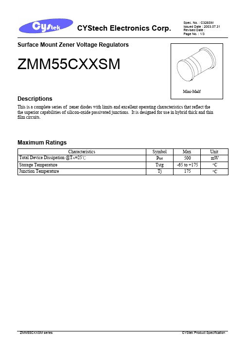
This is a complete series of zener diodes with limits and excellent operating characteristics that reflect thethe superior capabilities of silicon-oxide passivated junctions. It is designed for use in hybrid thick and thinfilm circuits.Maximum RatingsUnit Characteristics SymbolMaxTotal Device Dissipation @T A=25℃P tot 500 mWStorage Temperature Tstg -65 to +175 °CJunction Temperature Tj 175 °CElectrical Characteristics (T L=30℃, unless otherwise noted, V F=1.0V Max @I F=100mA for all types.)Test Current Maximum ZenerImpedance(Note 2)Maximum ReverseLeakage CurrentDevice NominalZenerVoltageVz at Iz T(V)(Note1)I ZT(mA)Z ZT atI ZT(Ω)Z ZK atI ZK=1mA(Ω)TypicalTemperatureCoefficient(%/℃) I R(μA)TestVoltage(V)MaximumRegulationCurrentI ZM(mA)(Note 3)ZMM55C2V4 2.28-2.56 5 85 600 -0.070 50 1.0 150 ZMM55C2V7 2.5-2.9 5 85 600 -0.070 10 1.0 135 ZMM55C3V0 2.8-3.2 5 85 600 -0.070 4 1.0 125 ZMM55C3V3 3.1-3.5 585 600 -0.065 2 1.0115ZMM55C3V6 3.4-3.8 585 600 -0.060 2 1.0105ZMM55C3V9 3.7-4.1 585 600 -0.050 2 1.095ZMM55C4V3 4.0-4.6 575 600 -0.025 1 1.090ZMM55C4V7 4.4-5.0 560 600 -0.010 0.5 1.085ZMM55C5V1 4.8-5.4 535 550 +0.015 0.1 1.080ZMM55C5V6 5.2-6.0 525 450 +0.025 0.1 1.070ZMM55C6V2 5.8-6.6 510 200 +0.035 0.1 2.0 64 ZMM55C6V8 6.4-7.2 58 150 +0.045 0.1 3.0 58 ZMM55C7V5 7.0-7.9 5 7 50 +0.050 0.1 5.0 53 ZMM55C8V2 7.7-8.7 5 7 50 +0.050 0.1 6.0 47 ZMM55C9V1 8.5-9.6 5 10 50 +0.060 0.1 7.0 43 ZMM55C10 9.4-10.6 5 15 70 +0.070 0.1 7.5 40 ZMM55C1110.4-11.6 5 20 70 +0.070 0.1 8.5 36 ZMM55C1211.4-12.7 5 20 90 +0.070 0.19.0 32 ZMM55C1312.4-14.1 526 110 +0.0700.110 29 ZMM55C1513.8-15.6 530 110 +0.0700.111 27 ZMM55C1615.3-17.1 540 170 +0.0700.112 24 ZMM55C1816.8-19.1 550 170 +0.0700.114 21 ZMM55C2018.8-21.2 555 220 +0.070 0.115 20 ZMM55C2220.8-23.3 5 55 220 +0.070 0.1 17 18 ZMM55C2422.8-25.6 5 80 220 +0.080 0.118 16 ZMM55C2725.1-28.9 580 220 +0.0800.120 14 ZMM55C3028-32 580 220 +0.0800.122 13 ZMM55C3331-35 580 220 +0.0800.124 12 ZMM55C3634-38 580 220 +0.0800.127 11 ZMM55C3937-41 2.5 90 500 +0.0800.130 10 ZMM55C4340-46 2.590 600 +0.0800.133 9.2 ZMM55C4744-50 2.5110 700 +0.0800.136 8.5 Note: 1.The type numbers listed have zener voltage min/max as shown. Device tolerance of ±2% are indicated by a “B”instead of a “C”. Zener voltage is measured with the device junction in thermal equilibrium at the lead temperatureof 30℃±1℃.2.Z ZT and Z ZK are measured by dividing the ac voltage drop across the device by the ac current applied. The specifiedlimits are for I Z(ac) =0.1I Z(dc) with the ac frequency = 1k Hz.3.This data was calculated using nominal voltages. The maximum current handling capability on a worse case basis islimited by the actual zener voltage at the operating point and the powered derating curve.Mini- Melf (SOD-80C) Dimension*:Typical Inches Millimeters Inches MillimetersDIMMin. Max. Min. Max. DIMMin. Max. Min. Max.A 0.0512 0.0591 1.30 1.50 C 0.0118 0.0197 0.30 0.50B 0.0118 0.0197 0.30 0.50 D 0.1260 0.1417 3.2 3.6Notes : 1.Controlling dimension : millimeters. 2.Maximum lead thickness includes lead finish thickness, and minimum lead thickness is the minimum thickness of base material.3.If there is any question with packing specification or packing method, please contact your local CYStek sales office.Important Notice:• All rights are reserved. Reproduction in whole or in part is prohibited without the prior written approval of CYStek.• CYStek reserves the right to make changes to its products without notice.• CYStek semiconductor products are not warranted to be suitable for use in Life-Support Applications, or systems.• CYStek assumes no liability for any consequence of customer product design, infringement of patents, or application assistance.ABCDCathode MarkLL-34 Mini-Melf SOD-80CCYStek package code:SM。
HSC277中文资料
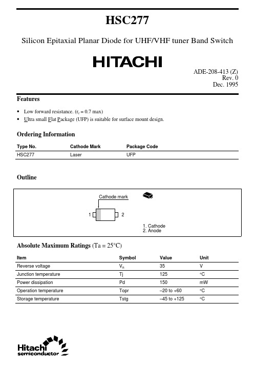
HSC277Silicon Epitaxial Planar Diode for UHF/VHF tuner Band SwitchADE-208-413 (Z)Rev. 0Dec. 1995 Features• Low forward resistance. (r f = 0.7max)• U l tra small F l at P a ckage (UFP) is suitable for surface mount design.Ordering InformationType No.Cathode Mark Package CodeHSC277Laser UFPOutlineAbsolute Maximum Ratings (Ta = 25°C)Item Symbol Value Unit35VReverse voltage VRJunction temperature Tj125°CPower dissipation Pd150mWOperation temperature Topr–20 to +60°CStorage temperature Tstg–45 to +125°CHSC2772Electrical Characteristics (Ta = 25°C)ItemSymbol Min Typ Max Unit Test Condition Reverse voltage V R 35——V I R = 10µA Reverse current I R ——50µA V R = 25V Forward voltage V F —— 1.0V I F = 10mA Capacitance C —— 1.2pF V R = 6V, f = 1MHz Forward resistancer f——0.7ΩI F = 2mA, f = 100MHzFig.1 Forward current Vs. Forward voltageHSC277Fig.2 Reverse current Vs. Reverse voltageFig.3 Capacitance Vs. Reverse voltage3HSC277Fig.4 Forward resistance Vs. Forward current 4HSC277 Package Dimensions5Cautions1.Hitachi neither warrants nor grants licenses of any rights of Hitachi’s or any third party’s patent,copyright, trademark, or other intellectual property rights for information contained in this document.Hitachi bears no responsibility for problems that may arise with third party’s rights, includingintellectual property rights, in connection with use of the information contained in this document.2.Products and product specifications may be subject to change without notice. Confirm that you have received the latest product standards or specifications before final design, purchase or use.3.Hitachi makes every attempt to ensure that its products are of high quality and reliability. However,contact Hitachi’s sales office before using the product in an application that demands especially high quality and reliability or where its failure or malfunction may directly threaten human life or cause risk of bodily injury, such as aerospace, aeronautics, nuclear power, combustion control, transportation,traffic, safety equipment or medical equipment for life support.4.Design your application so that the product is used within the ranges guaranteed by Hitachi particularly for maximum rating, operating supply voltage range, heat radiation characteristics, installationconditions and other characteristics. Hitachi bears no responsibility for failure or damage when used beyond the guaranteed ranges. Even within the guaranteed ranges, consider normally foreseeable failure rates or failure modes in semiconductor devices and employ systemic measures such as fail-safes, so that the equipment incorporating Hitachi product does not cause bodily injury, fire or other consequential damage due to operation of the Hitachi product.5.This product is not designed to be radiation resistant.6.No one is permitted to reproduce or duplicate, in any form, the whole or part of this document without written approval from Hitachi.7.Contact Hitachi’s sales office for any questions regarding this document or Hitachi semiconductor products.Hitachi, Ltd.Semiconductor & Integrated Circuits.Nippon Bldg., 2-6-2, Ohte-machi, Chiyoda-ku, Tokyo 100-0004, Japan Tel: Tokyo (03) 3270-2111 Fax: (03) 3270-5109Copyright ' Hitachi, Ltd., 1999. All rights reserved. Printed in Japan.Hitachi Asia Pte. Ltd.16 Collyer Quay #20-00Hitachi TowerSingapore 049318Tel: 535-2100Fax: 535-1533URLNorthAmerica : http:/Europe : /hel/ecg Asia (Singapore): .sg/grp3/sicd/index.htm Asia (Taiwan): /E/Product/SICD_Frame.htm Asia (HongKong): /eng/bo/grp3/index.htm Japan : http://www.hitachi.co.jp/Sicd/indx.htmHitachi Asia Ltd.Taipei Branch Office3F, Hung Kuo Building. No.167, Tun-Hwa North Road, Taipei (105)Tel: <886> (2) 2718-3666Fax: <886> (2) 2718-8180Hitachi Asia (Hong Kong) Ltd.Group III (Electronic Components)7/F., North Tower, World Finance Centre,Harbour City, Canton Road, Tsim Sha Tsui,Kowloon, Hong Kong Tel: <852> (2) 735 9218Fax: <852> (2) 730 0281 Telex: 40815 HITEC HXHitachi Europe Ltd.Electronic Components Group.Whitebrook ParkLower Cookham Road MaidenheadBerkshire SL6 8YA, United Kingdom Tel: <44> (1628) 585000Fax: <44> (1628) 778322Hitachi Europe GmbHElectronic components Group Dornacher Stra§e 3D-85622 Feldkirchen, Munich GermanyTel: <49> (89) 9 9180-0Fax: <49> (89) 9 29 30 00Hitachi Semiconductor (America) Inc.179 East Tasman Drive,San Jose,CA 95134 Tel: <1> (408) 433-1990Fax: <1>(408) 433-0223For further information write to:。
EN27C512中文资料(List Unclassifed)中文数据手册「EasyDatasheet - 矽搜」

4
芯片中文手册,看全文,戳
EN27C512
READ模式
该EN27C512具有两个控制功能,这两者必须逻辑满足以
获得在输出数据.芯片使能(
CE )是功率控制和应当用于
设备选择.输出使能(
OE )是输出控制和应使用栅极数据到
输出引脚,独立设备选择.假定地址是稳定,
地址访问时间(t
ACC )等于从延迟
在进入编程模式时12.75
± 0.25V被施加到
CE 是在V IL.用于编程,要编程数据被应用于与8位并行 数据引脚.
OE /VPP 销和
图5中QUIKRITE程TM序流程图显示EON交互式编程
算法.交互式算法采用20减少编程时间
编程脉冲和给每个地址仅尽可能多脉冲,是必要,以便
可靠地进行编程数据.之后每个脉冲被施加到一个给定地址,在该数据
30毫安操作(最大)
CMOS-和TTL兼容I / O
高可靠性CMOS技术
闭锁抗扰度100mA电流
从-1V到V CC + 1V二线控制(Βιβλιοθήκη OE & CE )
标准产品识别码
JEDEC标准引脚
28引脚PDIP
32引脚PLCC
28引脚TSOP(类型1)
商业和工业温度 范围
概述
所述EN27C512是一个低功率512Kbit,5V-只有一次性可编程(OTP)只读
芯片中文手册,看全文,戳
EN27C512 512KBIT EPROM (64K x 8)
EN27C512
特征
快速读取时间
:
-45,-55,-70,和-90ns
5V单电源供电
编程电压+ 12.75V
BZV55B27中文资料
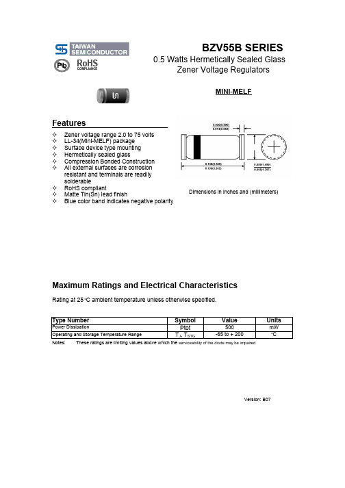
Pb RoHSCOMPLIANCEBZV55B SERIES 0.5 Watts Hermetically Sealed GlassZener Voltage RegulatorsFeatures Zener voltage range 2.0 to 75 voltsLL-34(Mini-MELF) packageSurface device type mountingHermetically sealed glassCompression Bonded ConstructionAll external surfaces are corrosionresistant and terminals are readilysolderableRoHS compliantMatte Tin(Sn) lead finishBlue color band indicates negative polarityMINI-MELFDimensions in inches and (millimeters)Maximum Ratings and Electrical CharacteristicsRating at 25o C ambient temperature unless otherwise specified.Type Number Symbol Value Units Power Dissipation Ptot500 mW Operating and Storage Temperature Range T J, T STG-65 to + 200 o CNotes: These ratings are limiting values above which the serviceability of the diode may be impairedVersion: B07Figure 1. Total Power Dissipation vs. Ambient TemperatureFigure 2. Typical Change of Working Voltage under OperatingConditions at T amb =25°CFigure 3. Typical Change of Working Voltage vs. JunctionTemperature1201600100300400500600P t o t - T o t a l P o w e r D i s s i p a t i o n (m W )T am b - Am b ient Temperat ure (°C)20020080401015201101001000V Z - V o l t a g e C h a n g e (m V )V Z - Z-V oltage (V )5- 60601201800.80.91.01.11.21.3V Z t n - R e l a t i v e V o l t a g e C h an g eT j - J u nction Temperat u re (°C)0Figure 4. Temperature Coefficient of Vz vs. Z-VoltageFigure 5. Diode Capacitance vs. Z-VoltageFigure 6. Forward Current vs. Forward Voltage30- 5051015V Z - Z-V oltage (V )504010200T K V Z - T e m p e r a t u r e C o e f f i c i e n t o f V Z (10-4/K )101550C D - D i o d e C a p a c i t a n c e (p F )V Z - Z-V oltage (V )20500.20.40.60.80.0010.010.1110100I F - F o r w a r d C u r r e n t (m A )V F - For w ard V oltage (V )Figure 7. Z-Current vs. Z-VoltageFigure 8. Z-Current vs. Z-Voltage820020406080I Z - Z -C u r r e n t (m A )4612V Z - Z-V oltage (V )152025300I Z - Z -C u r r e n t (m A )V Z - Z-Voltage (V )Figure 9. Differential Z-Resistance vs. Z-Voltage051015201101001000(Ω)V Z - Z-V oltage (V )r Z - D i f f e r e n t i a l Z -R e s i s t a n c e Figure 10. Thermal ResponseZ t h p - T h e r m a l R e s i s t a n c e f o r P u l s e C o n d . (K W )t P - P u lse Length (ms)10-1100101102ELECTRICAL CHARACTERISTICS (TA=25O C unless otherwise noted)Type Z ZT @ I ZT IR @ VR Number V Z V Z I ZT Ohms I ZK Z ZK @ I ZK uA VR Min (V)Max (V)mA Max mA Ohms MaxV BZV55B2V0 1.96 2.045100 1.060050 1.0BZV55B2V2 2.16 2.245100 1.060050 1.0BZV55B2V4 2.35 2.45585 1.060050 1.0BZV55B2V7 2.65 2.75585 1.060010 1.0BZV55B3V0 2.94 3.06585 1.06004 1.0BZV55B3V3 3.23 3.37585 1.06002 1.0BZV55B3V6 3.53 3.67585 1.06002 1.0BZV55B3V9 3.82 3.98585 1.06002 1.0BZV55B4V3 4.21 4.39575 1.06001 1.0BZV55B4V7 4.61 4.79560 1.06000.5 1.0BZV55B5V1 5.00 5.2535 1.05500.1 1.0BZV55B5V6 5.49 5.71525 1.04500.1 1.0BZV55B6V2 6.08 6.32510 1.02000.1 2.0BZV55B6V8 6.66 6.9458 1.01500.1 3.0BZV55B7V57.357.6557 1.0500.1 5.0BZV55B8V28.048.3657 1.0500.1 6.2BZV55B9V18.929.28510 1.0500.1 6.8BZV55B109.8010.2515 1.0700.17.5BZV55B1110.4011.22520 1.0700.18.2BZV55B1211.4012.24520 1.0900.19.1BZV55B1312.7413.26526 1.01100.110BZV55B1514.7015.30530 1.01100.111BZV55B1615.6816.32540 1.01700.112BZV55B1817.6418.36550 1.01700.113BZV55B2019.6020.40555 1.02200.115BZV55B2221.5622.44555 1.02200.116BZV55B2423.5224.48580 1.02200.118BZV55B2726.4627.54280 1.02200.120BZV55B3029.4030.60280 1.02200.122BZV55B3332.3433.66280 1.02200.124BZV55B3635.2836.72280 1.02200.127BZV55B3938.2239.782900.55000.128BZV55B4342.1443.862900.56000.132BZV55B4746.0647.9421100.57000.135BZV55B5149.9852.0221250.57000.138BZV55B5654.8857.1221350.510000.142BZV55B6260.7663.24 2.51500.510000.147BZV55B6866.6469.36 2.51600.510000.151BZV55B7573.5076.502.51700.510000.156VF Forward Voltage = 1.0v Maximum @ IF=100mA for all types.Notes: 1. The type numbers listed have zener voltage min/max limits as shown.2. The zener impedance is derived from the 60-cycle ac voltage, which results when an ac current having an rms value equal to 10% of the dc zener current (I ZT or I ZK ) is superimposed to I ZT or I ZK .Version: B 07(Volts)V Z @ I ZT。
BZV55B5V1中文资料
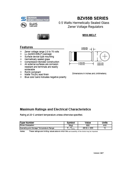
Pb RoHSCOMPLIANCEBZV55B SERIES 0.5 Watts Hermetically Sealed GlassZener Voltage RegulatorsFeatures Zener voltage range 2.0 to 75 voltsLL-34(Mini-MELF) packageSurface device type mountingHermetically sealed glassCompression Bonded ConstructionAll external surfaces are corrosionresistant and terminals are readilysolderableRoHS compliantMatte Tin(Sn) lead finishBlue color band indicates negative polarityMINI-MELFDimensions in inches and (millimeters)Maximum Ratings and Electrical CharacteristicsRating at 25o C ambient temperature unless otherwise specified.Type Number Symbol Value Units Power Dissipation Ptot500 mW Operating and Storage Temperature Range T J, T STG-65 to + 200 o CNotes: These ratings are limiting values above which the serviceability of the diode may be impairedVersion: B07Figure 1. Total Power Dissipation vs. Ambient TemperatureFigure 2. Typical Change of Working Voltage under OperatingConditions at T amb =25°CFigure 3. Typical Change of Working Voltage vs. JunctionTemperature1201600100300400500600P t o t - T o t a l P o w e r D i s s i p a t i o n (m W )T am b - Am b ient Temperat ure (°C)20020080401015201101001000V Z - V o l t a g e C h a n g e (m V )V Z - Z-V oltage (V )5- 60601201800.80.91.01.11.21.3V Z t n - R e l a t i v e V o l t a g e C h an g eT j - J u nction Temperat u re (°C)0Figure 4. Temperature Coefficient of Vz vs. Z-VoltageFigure 5. Diode Capacitance vs. Z-VoltageFigure 6. Forward Current vs. Forward Voltage30- 5051015V Z - Z-V oltage (V )504010200T K V Z - T e m p e r a t u r e C o e f f i c i e n t o f V Z (10-4/K )101550C D - D i o d e C a p a c i t a n c e (p F )V Z - Z-V oltage (V )20500.20.40.60.80.0010.010.1110100I F - F o r w a r d C u r r e n t (m A )V F - For w ard V oltage (V )Figure 7. Z-Current vs. Z-VoltageFigure 8. Z-Current vs. Z-Voltage820020406080I Z - Z -C u r r e n t (m A )4612V Z - Z-V oltage (V )152025300I Z - Z -C u r r e n t (m A )V Z - Z-Voltage (V )Figure 9. Differential Z-Resistance vs. Z-Voltage051015201101001000(Ω)V Z - Z-V oltage (V )r Z - D i f f e r e n t i a l Z -R e s i s t a n c e Figure 10. Thermal ResponseZ t h p - T h e r m a l R e s i s t a n c e f o r P u l s e C o n d . (K W )t P - P u lse Length (ms)10-1100101102ELECTRICAL CHARACTERISTICS (TA=25O C unless otherwise noted)Type Z ZT @ I ZT IR @ VR Number V Z V Z I ZT Ohms I ZK Z ZK @ I ZK uA VR Min (V)Max (V)mA Max mA Ohms MaxV BZV55B2V0 1.96 2.045100 1.060050 1.0BZV55B2V2 2.16 2.245100 1.060050 1.0BZV55B2V4 2.35 2.45585 1.060050 1.0BZV55B2V7 2.65 2.75585 1.060010 1.0BZV55B3V0 2.94 3.06585 1.06004 1.0BZV55B3V3 3.23 3.37585 1.06002 1.0BZV55B3V6 3.53 3.67585 1.06002 1.0BZV55B3V9 3.82 3.98585 1.06002 1.0BZV55B4V3 4.21 4.39575 1.06001 1.0BZV55B4V7 4.61 4.79560 1.06000.5 1.0BZV55B5V1 5.00 5.2535 1.05500.1 1.0BZV55B5V6 5.49 5.71525 1.04500.1 1.0BZV55B6V2 6.08 6.32510 1.02000.1 2.0BZV55B6V8 6.66 6.9458 1.01500.1 3.0BZV55B7V57.357.6557 1.0500.1 5.0BZV55B8V28.048.3657 1.0500.1 6.2BZV55B9V18.929.28510 1.0500.1 6.8BZV55B109.8010.2515 1.0700.17.5BZV55B1110.4011.22520 1.0700.18.2BZV55B1211.4012.24520 1.0900.19.1BZV55B1312.7413.26526 1.01100.110BZV55B1514.7015.30530 1.01100.111BZV55B1615.6816.32540 1.01700.112BZV55B1817.6418.36550 1.01700.113BZV55B2019.6020.40555 1.02200.115BZV55B2221.5622.44555 1.02200.116BZV55B2423.5224.48580 1.02200.118BZV55B2726.4627.54280 1.02200.120BZV55B3029.4030.60280 1.02200.122BZV55B3332.3433.66280 1.02200.124BZV55B3635.2836.72280 1.02200.127BZV55B3938.2239.782900.55000.128BZV55B4342.1443.862900.56000.132BZV55B4746.0647.9421100.57000.135BZV55B5149.9852.0221250.57000.138BZV55B5654.8857.1221350.510000.142BZV55B6260.7663.24 2.51500.510000.147BZV55B6866.6469.36 2.51600.510000.151BZV55B7573.5076.502.51700.510000.156VF Forward Voltage = 1.0v Maximum @ IF=100mA for all types.Notes: 1. The type numbers listed have zener voltage min/max limits as shown.2. The zener impedance is derived from the 60-cycle ac voltage, which results when an ac current having an rms value equal to 10% of the dc zener current (I ZT or I ZK ) is superimposed to I ZT or I ZK .Version: B 07(Volts)V Z @ I ZT。
芯佰微电子 低噪声、精密运算放大器 CBM27数据手册说明书
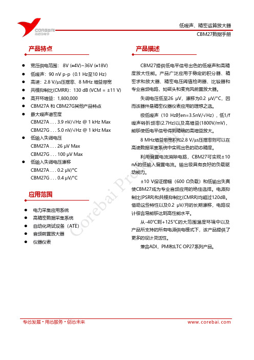
CBM27数据手册专芯发展 • 用芯服务 • 创芯未来www. corebai. com● 宽压供电范围: 8V (±4V)~36V (±18V) ● 低噪声:90 nV p-p (0.1 Hz 至10 Hz ) ● 高速:2.8 V/µs 压摆率、8 MHz 增益带宽 ● 共模抑制比(CMRR):130 dB (VCM = ±11 V) ● 高开环增益:1,800,000● CBM27A 和 CBM27G 其他产品特点 ● 最大噪声谱密度CBM27A . . . 3.9 nV/√Hz @ 1 kHz Max CBM27G . . . 5.0 nV/√Hz @ 1 kHz Max ● 低输入失调电压CBM27A . . . 26 μV Max CBM27G . . . 100 μV Max ● 低输入失调电压漂移CBM27A . . . 0.2 μV/°C CBM27G . . . 0.4 μV/°C● 电力采集应用系统● 高精密数据采集系统 ● 自动化测试设备(ATE )● 音频前置放大器 ● 仪器仪表CBM27提供低电平信号出色的低噪声和高精度放大性能。
产品广泛应用于稳定的积分器、精密求和放大器、精密电压阈值检测器、比较器和专业音频电路,如磁头和麦克风前置放大器。
失调电压低至26 μV ,漂移为0.2 μV/°C ,因而该器件是精密仪器仪表应用的理想之选。
极低噪声(10 Hz 时en=3.5nV/√Hz ), 低1/f 噪声转折频率(2.7Hz)以及高增益(1800V/mV),能够使低电平信号得到精确的高增益放大。
8 MHz 增益带宽积和2.8 V/µs 压摆率则可以在高速数据采集系统中实现出色的动态精度。
利用偏置电流消除电路,CBM27可实现±10nA 的低输入偏置电流。
输出级具有良好的负载驱动能力。
bzv55

DATA SHEETProduct specificationSupersedes data of 1999May 212002Feb 28BZV55 seriesVoltage regulator diodes1/3 page (Datasheet)M3D054Voltage regulator diodesBZV55 seriesFEATURES•Total power dissipation: max.500mW •Two tolerance series:±2%, and approx.±5%•Working voltage range: nom.2.4to 75V (E24range)•Non-repetitive peak reverse power dissipation:max.40W.APPLICATIONS•Low voltage stabilizers or voltage references.DESCRIPTIONLow-power voltage regulator diodes in small hermetically sealed glass SOD80C SMD packages. The diodes are available in the normalized E24±2% (BZV55-B) and approx.±5% (BZV55-C) tolerance range. The series consists of 37 types with nominal working voltages from 2.4to 75V.columnsMAM215kaFig.1Simplified outline (SOD80C) and symbol.The cathode is indicated by a yellow band.LIMITING VALUESIn accordance with the Absolute Maximum Rating System (IEC 60134).Note1.Device mounted on a ceramic substrate of 10×10×0.6mm.SYMBOL PARAMETERCONDITIONSMIN.MAX.UNIT I F continuous forward current −250mAI ZSM non-repetitive peak reverse current t p =100µs; square wave;T j =25°C prior to surge see Tables 1and 2A P tot total power dissipationT amb ≤50°C; note 1−400mW tie-point ≤50°C; note 1−500mW P ZSM non-repetitive peak reverse power dissipationt p =100µs; square wave;T j =25°C prior to surge; see Fig.3−40W T stg storage temperature −65+200°C T j junction temperature−65+200°CVoltage regulator diodes BZV55 seriesELECTRICAL CHARACTERISTICSTotal BZV55-B and BZV55-C seriesT j=25°C; unless otherwise specified.SYMBOL PARAMETER CONDITIONS MAX.UNIT V F forward voltage I F=10mA; see Fig.40.9V I R reverse currentBZV55-B/C2V4V R=1V50µABZV55-B/C2V7V R=1V20µABZV55-B/C3V0V R=1V10µABZV55-B/C3V3V R=1V5µABZV55-B/C3V6V R=1V5µABZV55-B/C3V9V R=1V3µABZV55-B/C4V3V R=1V3µABZV55-B/C4V7V R=2V3µABZV55-B/C5V1V R=2V2µABZV55-B/C5V6V R=2V1µABZV55-B/C6V2V R=4V3µABZV55-B/C6V8V R=4V2µABZV55-B/C7V5V R=5V1µABZV55-B/C8V2V R=5V700nABZV55-B/C9V1V R=6V500nABZV55-B/C10V R=7V200nABZV55-B/C11V R=8V100nABZV55-B/C12V R=8V100nABZV55-B/C13V R=8V100nABZV55-B/C15to BZV55-B/C75V R=0.7V Znom50nA4Product specificationBZV55 series3V3 3.23 3.37 3.1 3.53506008595−3.5−2.40450 6.03V6 3.53 3.67 3.4 3.83756008590−3.5−2.40450 6.03V9 3.82 3.98 3.7 4.14006008590−3.5−2.50450 6.04V3 4.21 4.39 4.0 4.64106008090−3.5−2.50450 6.04V7 4.61 4.79 4.4 5.04255005080−3.5−1.40.2300 6.05V1 5.00 5.20 4.8 5.44004804060−2.7−0.8 1.2300 6.05V6 5.49 5.71 5.2 6.0804001540−2.0 1.2 2.5300 6.06V2 6.08 6.32 5.8 6.6401506100.4 2.3 3.7200 6.06V8 6.66 6.94 6.47.23080615 1.2 3.0 4.5200 6.07V57.357.657.07.93080615 2.5 4.0 5.3150 4.08V28.048.367.78.74080615 3.2 4.6 6.2150 4.09V18.929.288.59.640100615 3.8 5.57.0150 3.0109.8010.209.410.650150820 4.5 6.48.090 3.01110.8011.2010.411.6501501020 5.47.49.085 2.51211.8012.2011.412.7501501025 6.08.410.085 2.51312.7013.3012.414.150********.09.411.080 2.51514.7015.3013.815.65020010309.211.413.075 2.01615.7016.3015.317.150200104010.412.414.075 1.51817.6018.4016.819.150225104512.414.416.070 1.52019.6020.4018.821.260225155512.315.618.060 1.52221.6022.4020.823.360250205514.117.620.060 1.252423.5024.5022.825.660250257015.919.622.0551.255Product specificationBZV55 series3635.3036.7034.038.080350359026.031.837.4450.83938.2039.8037.041.0803504013028.734.841.2450.74342.1043.9040.046.0853754515031.438.846.6400.64746.1047.9044.050.0853755017035.042.951.8400.55150.0052.0048.054.0904006018038.646.957.2400.45654.9057.1052.060.01004257020042.252.063.8400.36260.8063.2058.066.01204508021558.864.471.6350.36866.6069.4064.072.01504759024065.671.779.8350.257573.5076.5070.079.01705009525573.480.288.6350.2Voltage regulator diodesBZV55 seriesTHERMAL CHARACTERISTICS Note1.Device mounted on a ceramic substrate of 10×10×0.6mm.SYMBOL PARAMETERCONDITIONSVALUE UNIT R th j-tp thermal resistance from junction to tie-point300K/W R th j-a thermal resistance from junction to ambient see Fig.2 and note 1380K/WGRAPHICAL DATAhandbook, full pagewidth10−1110102103104105MBG930102101103t p (ms)t pt p TTδ =0.020.01≤0.0010.750.500.330.200.100.05δ = 1R th j-a (K/W)Fig.2 Thermal resistance from junction to ambient as a function of pulse duration.Voltage regulator diodes BZV55 seriesFig.3Maximum permissible non-repetitive peak reverse power dissipation versus duration.handbook, halfpageMBG8011031duration (ms)P ZSM (W)1010210−1101(1)(2)(1)T j =25°C (prior to surge).(2)T j =150°C (prior to surge).Fig.4Typical forward current as a function of forward voltage.handbook, halfpage0.61.03001000200MBG7810.8V F (V)I F (mA)T j =25°C.Fig.5Temperature coefficient as a function of working current; typical values.handbook, halfpage060−2−3−1MBG7832040I Z (mA)S Z (mV/K)4V33V93V63V02V42V73V3BZV55-B/C2V4to BZV55-B/C4V3.T j =25to 150°C.Fig.6Temperature coefficient as a function of working current; typical values.handbook, halfpage0201610−55MBG7824812I Z (mA)S Z (mV/K)4V71211109V18V27V56V86V25V65V1BZV55-B/C4V7to BZV55-B/C12.T j =25to 150°C.Voltage regulator diodesBZV55 seriesPACKAGE OUTLINEREFERENCESOUTLINE VERSION EUROPEAN PROJECTIONISSUE DATE IEC JEDECEIAJNote1. The marking band indicates the cathode.SOD80C100H0197-06-20Hermetically sealed glass surface mounted package; 2 connectorsSOD80CUNIT D mm 1.601.453.73.30.3H L DIMENSIONS (mm are the original dimensions)HDLL(1)1 2 mmscalekaVoltage regulator diodesBZV55 seriesDATA SHEET STATUS Notes1.Please consult the most recently issued data sheet before initiating or completing a design.2.The product status of the device(s) described in this data sheet may have changed since this data sheet waspublished. The latest information is available on the Internet at URL .DATA SHEET STATUS (1)PRODUCT STATUS (2)DEFINITIONSObjective dataDevelopmentThis data sheet contains data from the objective specification for product development. Philips Semiconductors reserves the right to change the specification in any manner without notice.Preliminary data QualificationThis data sheet contains data from the preliminary specification.Supplementary data will be published at a later date. PhilipsSemiconductors reserves the right to change the specification without notice, in order to improve the design and supply the best possible product.Product data ProductionThis data sheet contains data from the product specification. Philips Semiconductors reserves the right to make changes at any time in order to improve the design, manufacturing and supply. Changes will be communicated according to the Customer Product/Process Change Notification (CPCN) procedure SNW-SQ-650A.DEFINITIONSShort-form specification The data in a short-form specification is extracted from a full data sheet with the same type number and title. For detailed information see the relevant data sheet or data handbook.Limiting values definition Limiting values given are in accordance with the Absolute Maximum Rating System (IEC 60134). Stress above one or more of the limiting values may cause permanent damage to the device.These are stress ratings only and operation of the device at these or at any other conditions above those given in the Characteristics sections of the specification is not implied.Exposure to limiting values for extended periods may affect device reliability.Application information Applications that are described herein for any of these products are forillustrative purposes only. Philips Semiconductors make no representation or warranty that such applications will be suitable for the specified use without further testing or modification.DISCLAIMERSLife support applications These products are not designed for use in life support appliances, devices, or systems where malfunction of these products canreasonably be expected to result in personal injury.Philips Semiconductors customers using or selling these products for use in such applications do so at their own risk and agree to fully indemnify Philips Semiconductors for any damages resulting from such application.Right to make changes Philips Semiconductorsreserves the right to make changes,without notice,in the products, including circuits, standard cells, and/or software, described or contained herein in order to improve design and/or performance. PhilipsSemiconductors assumes no responsibility or liability for the use of any of these products,conveys no licence or title under any patent, copyright, or mask work right to these products,and makes no representations or warranties that these products are free from patent, copyright, or mask work right infringement, unless otherwise specified.Voltage regulator diodes BZV55 seriesNOTESPhilips Semiconductors Product specification Voltage regulator diodes BZV55 seriesNOTES2002Feb2811Philips Semiconductors – a worldwide companyContact informationFor additional information please visit .Fax:+31402724825For sales offices addresses send e-mail to:sales.addresses@.© Koninklijke Philips Electronics N.V. 2002SCA74 All rights are reserved. Reproduction in whole or in part is prohibited without the prior written consent of the copyright owner.The information presented in this document does not form part of any quotation or contract,is believed to be accurate and reliable and may be changed without notice. No liability will be accepted by the publisher for any consequence of its use. Publication thereof does not convey nor imply any license under patent- or other industrial or intellectual property rights.Printed in The Netherlands613514/03/pp12 Date of release:2002Feb28Document order number: 939775009386。
埃森电子系统55型号预制分布板的说明说明书

Eaton 1967805I-32G1400-0S-44. S55, 1f, MCB 3 gr 2 ALS 44General specificationsEaton Systeem 55 compact distribution board pre-wired 1967805I-32G1400-0S-448711426213531292 mm140 mm 234 mm1.69 kg EN 61439-3Product Name Catalog Number Model CodeEAN Product Length/Depth Product Height Product Width Product Weight Certifications220 mmNoneSurface mounted (plaster)Miniature- / earth leakage circuit breaker 3312None40 ANone1IP3X (housing/enclosure)IP3X eaton-insulated-boards-systeem55-lv-systems-dimensions-002.eps IL014053ZUEnclosure heightCooker groupNumber of poles at main switchNumber of switches (earth leakage 300 mA) Mounting methodProtected byNumber of groupsNumber of light groups protected by 30 mA Number of circuit breakers (earth leakage) Width in number of modular spacings Fitted with:Number of arc fault detection devices AFDD Current rating of RCD and main switch Functional groupNumber of phasesNumber of outgoing waysDegree of protection DrawingsInstallation instructionsSpecial featuresGroup cabinet Group cabinets for residential construction, (retail) business, offices and practice rooms according to NEN 1010 with earth leakage protection of all groups unless otherwise specified Snap-in, robust plastic mounting frame with integrated DIN profile(s) Integrated, divided pipe entry with 17 pipe entry openings diameter 16/19 mm, of which 10 in the lower row Lid with manual sealable quick fasteners Standard connection block for phase and zero Connection block (= option) for outgoing groups of lower row components number of poles and nominal current main switch and earth leakage switches the sameNumber of groups (total)3ColorBlack RAL 9005 (bins and lid)Light gray (RAL 7035, mounting frame)Built-in depth - max0 mmFunctionsExtension possibleMaterialThermoplastic plasticNumber of direct groupsCurrent rating of main switch0 AEnclosure materialPlasticBuilt-in depth - min0 mmTypeGroup enclosure Group enclosures with miniature circuit breakersNumber of switches (earth leakage 30 mA)2Number of groups behind earth leakage switch3Main switchNoneEaton Corporation plc Eaton House30 Pembroke Road Dublin 4, Ireland © 2023 Eaton. All Rights Reserved. Eaton is a registered trademark.All other trademarks areproperty of their respectiveowners./socialmedia。
Philips X-Line 55BDL3207X 55英寸直LED背光全高清显示屏说明书

Philips Signage SolutionsVideo Wall Display55"Direct LED Backlight Full HD 700cd/m²55BDL3207X Impressive videowall Inspire your team and guestsTake presentations and corporate branding to the next level. The Philips X-LineVideowall display brings your content to life to ensure absolute audience engagement in every setting with Pure Colour Pro.Effortless setup. Total control.•Operate, monitor and maintain with CMND & Control•Add Android processing power with an optional CRD50 moduleCost-effective system solution•FailOver ensures content is always playingBrilliant images. Endless possibilities.•Full HD monitors. Brilliant images. Clear contrast•IPS panel: rich color consistency from every angle•Ultra-narrow bezels. For distraction-free imagesPowerful system solution•Energy-saving automatic backlight control•OPS slot allows for PC embedding without cabling•Tiling mode. Create tiled 4K videowalls of any sizeIssue date 2022-11-10Version: 7.0.112 NC: 8670 001 82101EAN: 87 12581 78595 6© 2022 Koninklijke Philips N.V.All Rights reserved.Specifications are subject to change without notice. Trademarks are the property of Koninklijke Philips N.V. or their respective Specifications Video Wall Display 55" Direct LED Backlight, Full HD, 700cd/m²HighlightsCMND & Control Run your display network over a local (LAN) connection. CMND & Control allows you to perform vital functions like controlling inputs and monitoring display status. Whether you're in charge of one screen or 100.FailOver From waiting room to meeting room, never show a blank screen. FailOver lets your Philips Professional Display switch automatically between primary and secondary inputs ensuring content keeps playing even if the primary source goes down. Simply set a list of alternate inputs to be sure your business is always on.OPS slot Integrate a full-power PC or Android-powered CRD50 module directly into your Philips Professional Display. The OPS slot contains all the connections you need to run your slot-in solution, including a power supply.Optional CRD50 module Embed an Android System-on-Chip (SoC) in your Philips Professional Display. The optional CRD50 module is an OPS device that enables Android processing power without the need for cables. Simply slide into the OPS slot, which contains all the connections needed to run the module (including power supply).Tiling mode Connect two or more Philips professional displays to create a tiled videowall-without the need for external devices. A single player takes care of content, whether you have four screens or 40. 4K content is fully supported, and if you're showing that content on four screens you get the best possible dot-by-dot resolution.Pure Colour Pro Boost image quality with Pure Colour Pro. Delivering higher luminance through custom colour temperature settings and advanced gamma calibration, content looks crisper and more radiantfor stunning realism with a visual pop.Picture/Display •Diagonal screen size: 54.6 inch / 138.7 cm •Panel resolution: 1920x1080p •Optimum resolution: 1920 x 1080 @ 60 Hz •Brightness: 700 cd/m²•Dynamic contrast ratio: 500,000:1•Response time (typical): 8 ms •Aspect ratio: 16:9•Viewing angle (H / V): 178 / 178 degree •Pixel pitch: 0.63 x 0.63 mm •Display colors: 1.07 B •Contrast ratio (typical): 1100:1•Haze:28%Supported Display Resolution •Computer formats Resolution Refresh rate 1024 x 768 60, 75Hz 1280 x 1024 60Hz 1280 x 768 60Hz 1280 x 800 60Hz 1280 x 960 60Hz 1360 x 768 60Hz 1366 x 768 60Hz 1600 x 1200 60Hz 1920 x 1080 60Hz 640 x 480 60, 72, 75Hz 720 x 400 70Hz 800 x 600 60, 75Hz •Video formats Resolution Refresh rate 720p 50, 60Hz 1080i 25, 30Hz 1080p 50, 60Hz 2160P 50 60Hz ((HDMI/OPS/DP)Connectivity •Video input: DVI-D (x1), HDMI 2.0 (x2), VGA (Analog D-Sub) (x1), Display Port1.3 (x1)•Audio input: 3.5 mm mini jack (x1)•Video output: DisplayPort 1.3 (x1)•Audio output: 3.5 mm Mini Jack (x1)•External control: IR (in) 3.5 mm jack, LAN RJ45 (x2), Signal loopthrough RJ45(x2)•Other connections: OPS, USB 2.0 (x1), Thermal sensorConvenience •Placement: Landscape (24/7), Portrait (24/7)•Tiled Matrix: Up to 15 x 15•Screen saving functions: Pixel Shift, Low Bright •Signal loop through: DisplayPort, RJ45•Ease of installation: Carrying Handles, Smart Insert •Energy saving functions: Smart Power •Network controllable: LAN (RJ45)Operating conditions •Temperature range (operation): 0 ~ 40 °C •Temperature range (storage): -20 ~ 60 °C •Altitude: 0 ~ 3000 m •MTBF: 50,000 hour(s)•Humidity range (operation)[RH]: 20 - 80% (without condensation)•Humidity range (storage) [RH]: 5 - 95% (without condensation)Power •Consumption (Typical): 170 W •Consumption (Max): 340 W •Consumption (On mode): 115 W •Standby power consumption: <0.50 W •Energy Label Class: G Sound •Built-in speakers: 2 x 10W (RMS)Accessories •Included Accessories: Gap pad x3, IR sensor cable (1.8 m) (x1), Quick start guide (x1), Remote control & AAA batteries, RJ45 / RS232 converter, Wire Clamper (x3), Power cord, DP cable (x1), RJ45 cable (x1), Edge alignment pin (x2), Kit-1 (x1), Kit-2 (x2)Miscellaneous •On-Screen Display Languages: Arabic, English, French, German, Italian, Japanese, Polish, Russian, Spanish, Simplified Chinese, Turkish, Traditional Chinese •Regulatory approvals: CE, FCC, Class A, RoHS, CB, ETL, BSMI, PSE •Warranty: 3 years warranty Dimensions •Smart Insert mount: 100mm x 100mm, 6xM4xL6•Set dimensions (W x H x D): 1213.4 x 684.2 x 98.2 mm(D@WallMount)/99.35 mm(D@Handle) mm •Set dimensions in inch (W x H x D): 47.77 x 26.94 x 3.87 (D@WallMount)/3.91 (D@Handle) inch •Bezel width: 3.5mm •Wall Mount: 400mm x 400mm, M6•Product weight: 26.17 kg。
