CD4089BPWR;CD4089BE;CD4089BPWRE4;CD4089BPWRG4;CD4089BNSR;中文规格书,Datasheet资料
CD4085BPWR,CD4085BPWR,CD4085BPWR,CD4085BE,CD4085BME4,CD4085BMG4,CD4085BEE4, 规格书,Datasheet 资料
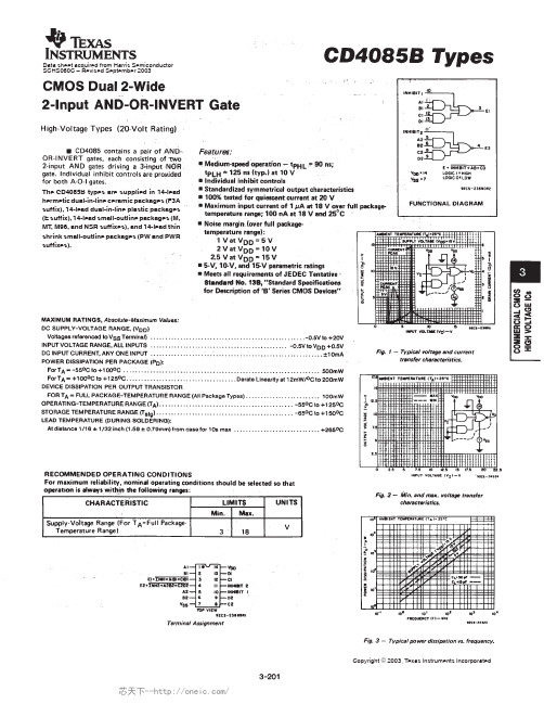
The CD4085B types are supplied in 14-leadhermetic dual-in-line ceramic packages (F3Asuffix), 14-lead dual-in-line plastic packages(E suffix), 14-lead small-outline packages (M,MT, M96, and NSR suffixes), and 14-lead thinshrink small-outline packages (PW and PWRsuffixes).Copyright © 2003, Texas Instruments IncorporatedAddendum-Page 1PACKAGING INFORMATIONOrderable DeviceStatus(1)Package Type PackageDrawingPins Package QtyEco Plan(2)Lead/Ball FinishMSL Peak Temp(3)Samples (Requires Login)CD4085BE ACTIVE PDIP N 1425Pb-Free (RoHS)CU NIPDAU N / A for Pkg Type CD4085BEE4ACTIVE PDIP N 1425Pb-Free (RoHS)CU NIPDAU N / A for Pkg TypeCD4085BF ACTIVE CDIP J 141TBD A42N / A for Pkg Type CD4085BF3A ACTIVE CDIP J 141TBD A42N / A for Pkg TypeCD4085BM ACTIVE SOIC D 1450Green (RoHS & no Sb/Br)CU NIPDAU Level-1-260C-UNLIM CD4085BME4ACTIVE SOIC D 1450Green (RoHS & no Sb/Br)CU NIPDAU Level-1-260C-UNLIM CD4085BMG4ACTIVE SOIC D 1450Green (RoHS & no Sb/Br)CU NIPDAU Level-1-260C-UNLIM CD4085BMT ACTIVE SOIC D 14250Green (RoHS & no Sb/Br)CU NIPDAU Level-1-260C-UNLIM CD4085BMTE4ACTIVE SOIC D 14250Green (RoHS & no Sb/Br)CU NIPDAU Level-1-260C-UNLIM CD4085BMTG4ACTIVE SOIC D 14250Green (RoHS & no Sb/Br)CU NIPDAU Level-1-260C-UNLIM CD4085BPWR ACTIVE TSSOP PW 142000Green (RoHS & no Sb/Br)CU NIPDAU Level-1-260C-UNLIM CD4085BPWRE4ACTIVE TSSOP PW 142000Green (RoHS & no Sb/Br)CU NIPDAU Level-1-260C-UNLIM CD4085BPWRG4ACTIVETSSOPPW142000Green (RoHS & no Sb/Br)CU NIPDAU Level-1-260C-UNLIM(1)The marketing status values are defined as follows:ACTIVE: Product device recommended for new designs.LIFEBUY: TI has announced that the device will be discontinued, and a lifetime-buy period is in effect.NRND: Not recommended for new designs. Device is in production to support existing customers, but TI does not recommend using this part in a new design.PREVIEW: Device has been announced but is not in production. Samples may or may not be available.OBSOLETE: TI has discontinued the production of the device.(2)Eco Plan - The planned eco-friendly classification: Pb-Free (RoHS), Pb-Free (RoHS Exempt), or Green (RoHS & no Sb/Br) - please check /productcontent for the latest availability information and additional product content details.TBD: The Pb-Free/Green conversion plan has not been defined.Pb-Free (RoHS): TI's terms "Lead-Free" or "Pb-Free" mean semiconductor products that are compatible with the current RoHS requirements for all 6 substances, including the requirement that lead not exceed 0.1% by weight in homogeneous materials. Where designed to be soldered at high temperatures, TI Pb-Free products are suitable for use in specified lead-free processes.芯天下--/Pb-Free (RoHS Exempt): This component has a RoHS exemption for either 1) lead-based flip-chip solder bumps used between the die and package, or 2) lead-based die adhesive used between the die and leadframe. The component is otherwise considered Pb-Free (RoHS compatible) as defined above.Green (RoHS & no Sb/Br): TI defines "Green" to mean Pb-Free (RoHS compatible), and free of Bromine (Br) and Antimony (Sb) based flame retardants (Br or Sb do not exceed 0.1% by weight in homogeneous material)(3) MSL, Peak Temp. -- The Moisture Sensitivity Level rating according to the JEDEC industry standard classifications, and peak solder temperature.Important Information and Disclaimer:The information provided on this page represents TI's knowledge and belief as of the date that it is provided. TI bases its knowledge and belief on information provided by third parties, and makes no representation or warranty as to the accuracy of such information. Efforts are underway to better integrate information from third parties. TI has taken and continues to take reasonable steps to provide representative and accurate information but may not have conducted destructive testing or chemical analysis on incoming materials and chemicals. TI and TI suppliers consider certain information to be proprietary, and thus CAS numbers and other limited information may not be available for release.In no event shall TI's liability arising out of such information exceed the total purchase price of the TI part(s) at issue in this document sold by TI to Customer on an annual basis.OTHER QUALIFIED VERSIONS OF CD4085B, CD4085B-MIL :•Catalog: CD4085B•Military: CD4085B-MILNOTE: Qualified Version Definitions:•Catalog - TI's standard catalog product•Military - QML certified for Military and Defense ApplicationsAddendum-Page 2芯天下--/TAPE AND REEL INFORMATION*All dimensions are nominalDevicePackage Type Package Drawing Pins SPQReel Diameter (mm)Reel Width W1(mm)A0(mm)B0(mm)K0(mm)P1(mm)W (mm)Pin1Quadrant CD4085BMT SOIC D 14250330.016.4 6.59.0 2.18.016.0Q1CD4085BPWRTSSOPPW142000330.012.46.95.61.68.012.0Q1*All dimensions are nominalDevice Package Type Package Drawing Pins SPQ Length(mm)Width(mm)Height(mm) CD4085BMT SOIC D1*******.0367.038.0CD4085BPWR TSSOP PW142000367.0367.035.0IMPORTANT NOTICETexas Instruments Incorporated and its subsidiaries(TI)reserve the right to make corrections,enhancements,improvements and other changes to its semiconductor products and services per JESD46C and to discontinue any product or service per JESD48B.Buyers should obtain the latest relevant information before placing orders and should verify that such information is current and complete.All semiconductor products(also referred to herein as“components”)are sold subject to TI’s terms and conditions of sale supplied at the time of order acknowledgment.TI warrants performance of its components to the specifications applicable at the time of sale,in accordance with the warranty in TI’s terms and conditions of sale of semiconductor products.Testing and other quality control techniques are used to the extent TI deems necessary to support this warranty.Except where mandated by applicable law,testing of all parameters of each component is not necessarily performed.TI assumes no liability for applications assistance or the design of Buyers’products.Buyers are responsible for their products and applications using TI components.To minimize the risks associated with Buyers’products and applications,Buyers should provide adequate design and operating safeguards.TI does not warrant or represent that any license,either express or implied,is granted under any patent right,copyright,mask work right,or other intellectual property right relating to any combination,machine,or process in which TI components or services are rmation published by TI regarding third-party products or services does not constitute a license to use such products or services or a warranty or endorsement e of such information may require a license from a third party under the patents or other intellectual property of the third party,or a license from TI under the patents or other intellectual property of TI.Reproduction of significant portions of TI information in TI data books or data sheets is permissible only if reproduction is without alteration and is accompanied by all associated warranties,conditions,limitations,and notices.TI is not responsible or liable for such altered rmation of third parties may be subject to additional restrictions.Resale of TI components or services with statements different from or beyond the parameters stated by TI for that component or service voids all express and any implied warranties for the associated TI component or service and is an unfair and deceptive business practice. TI is not responsible or liable for any such statements.Buyer acknowledges and agrees that it is solely responsible for compliance with all legal,regulatory and safety-related requirements concerning its products,and any use of TI components in its applications,notwithstanding any applications-related information or support that may be provided by TI.Buyer represents and agrees that it has all the necessary expertise to create and implement safeguards which anticipate dangerous consequences of failures,monitor failures and their consequences,lessen the likelihood of failures that might cause harm and take appropriate remedial actions.Buyer will fully indemnify TI and its representatives against any damages arising out of the use of any TI components in safety-critical applications.In some cases,TI components may be promoted specifically to facilitate safety-related applications.With such components,TI’s goal is to help enable customers to design and create their own end-product solutions that meet applicable functional safety standards and requirements.Nonetheless,such components are subject to these terms.No TI components are authorized for use in FDA Class III(or similar life-critical medical equipment)unless authorized officers of the parties have executed a special agreement specifically governing such use.Only those TI components which TI has specifically designated as military grade or“enhanced plastic”are designed and intended for use in military/aerospace applications or environments.Buyer acknowledges and agrees that any military or aerospace use of TI components which have not been so designated is solely at the Buyer's risk,and that Buyer is solely responsible for compliance with all legal and regulatory requirements in connection with such use.TI has specifically designated certain components which meet ISO/TS16949requirements,mainly for automotive ponents which have not been so designated are neither designed nor intended for automotive use;and TI will not be responsible for any failure of such components to meet such requirements.Products ApplicationsAudio /audio Automotive and Transportation /automotiveAmplifiers Communications and Telecom /communicationsData Converters Computers and Peripherals /computersDLP®Products Consumer Electronics /consumer-appsDSP Energy and Lighting /energyClocks and Timers /clocks Industrial /industrialInterface Medical /medicalLogic Security /securityPower Mgmt Space,Avionics and Defense /space-avionics-defense Microcontrollers Video and Imaging /videoRFID OMAP Mobile Processors /omap TI E2E Community Wireless Connectivity /wirelessconnectivityMailing Address:Texas Instruments,Post Office Box655303,Dallas,Texas75265Copyright©2012,Texas Instruments Incorporated。
CD4069中文资料

CD4069中文资料CC4069由六个COS/MOS反相器电路组成。
此器件主要用作通用反相器、即用于不需要中功率TTL驱动和逻辑电平转换的电路中。
838电子CD4069引脚功能图交流测试电路和波形切换时间Absolute Maximum Ratings 绝对最大额定值:DC Supply Voltage 直流供电电压(VDD)-0.5V to +18 VDCInput Voltage输入电压(VIN)-0.5V to VDD +0.5 VDCStorage Temperature Range储存温度范围(TS)-65℃to +150℃Power Dissipation功耗(PD)Dual-In-Line 普通双列封装700 mWSmall Outline 小外形封装500 mWLead Temperature 焊接温度(TL)Soldering, 10 seconds)(焊接10秒)260℃IOLLOW Level OutputCurrent 输出低电平电流 (Note 4) VDD = 5V, VO = 0.4V 0.52 0.44 0.88 0.36 mAVDD = 10V, VO = 0.5V 1.3 1.1 2.25 0.9 VDD = 15V, VO =1.5V3.63.08.82.4IOHHIGH Level OutputCurrent 输出高电平电流 (Note 4) VDD = 5V, VO = 4.6V -0.52 -0.44 -0.88 -0.36 mAVDD = 10V, VO = 9.5V -1.3 -1.1 -2.25 -0.9 VDD = 15V, VO =13.5V -3.6-3.0 -8.8-2.4IINInputCurrent 输入电流 VDD = 15V, VIN = 0V-0.30 -10-5 -0.30 -1.0 μA VDD = 15V, VIN = 15V0.3010-50.301.0AC Electrical Characteristics 交流电气特性:Symbol符号Parameter 参数Conditions 条件 最小 典型 最大Units 单位tPHLor tPLHPropagation Delay Time from Input to Output 输入输出传播延迟时间VDD = 5V 50 90 nsVDD = 10V 30 60 VDD = 15V 25 50 tTHL or tTLH Transition Time 过渡时间 VDD = 5V80 150 ns VDD = 10V 50 100 VDD = 15V40 80 CIN Average Input Capacitance 平均输入电容 Any Gate6 15 pF CPDPower Dissipation Capacitance 功耗电容Any Gate(Note6)12pF精确长延时电路原理如上图所示。
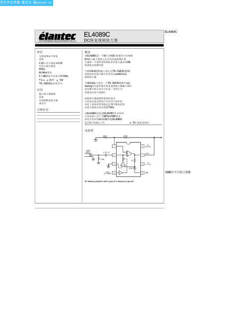
EL4089CS中文资料(Elantec Semiconductor)中文数据手册「EasyDatasheet - 矽搜」
a 25 C
12
25
II
mV
Ib a
IN a Input BiasCurrent
a 25 C
1
5
II
mA
Ib b
IN b Input BiasCurrent
a 25 C
18
150
II
mA
R
Transimpedance (Note 1)
a 25 C
180
800
II
kX
R
IN b Resistance
a 25 C
All parametershaving Min Max specificationsare guaranteed The Test Level column indicatesthe specific device testing actually
performed during production and Quality inspection Elantec performsmost electrical testsusing modern high-speed automatic test
20
V
X
CMRR
Common Mode Rejection Ratio (Note 2)
a 25 C
44
60
II
dB
V
Output Voltage Swing
a 25 C
12
13
II
V
I Restore Section
Short Circuit Current (IN a Only Driven to 0 5V)
3
TD is3 2in TD is3 2in
中华维修论坛-91xiubbs_com- P4系列CPU大全

双核心,EBD ,EM64T
HT EDB EM64T HT EDB EM64T
631(3.0GHz)641(3.2GHz)651 (3.4GHz)661(3.6GHz)671(3.8GHz)
520(2.8GHz)、530(3.0GHz)、540 (3.2GHz)、550(3.4GHz)、560(3.6GHz)、 570(3.8GHz) 520J(2.8GHz)、530J(3.0GHz)、540J (3.2GHz)、550J(3.4GHz)、560J(3.6GHz) 、570J(3.8GHz)
1.25V-1.4V 1.525V 1.525V 1.5V 1.5V 1.525V 1.525V
频率范围及规格 1.7G,1.8G,1.9G 2G,2.2G,2.4G,2.5G,2.6G,2.7G,2.8G
2.4GHz,2.53GHz,2.66GHz,2.8GHz
315(2.26GHz)320(2.4GHz),325(2.53GHz), 330(2.66GHz),335(2.8GHz)340(2.93GHz)345 (3.06GHz)350(3.2GHz)
3.8G 3.8G 3.8G 3.33G 3.8G 3.8G 2.6G 3.06G 3.4G 3.4G
200MHz 200MHz 200MHz 133MHz 200MHz 133MHz 100MHz 133MHz 200MHz 200MHz
800MHz 800MHz 800MHz 533MHz 800MHz 533MHz 400MHz 533MHz 800MHz 800MHz
1.25V-1.4V
28K 28K 28K 28K 32K 32K 20K 20K 20K 20K
1M 1M 1M 1M 1M 1M 512K 512K 512K 512K+2M
CD4070BPWRG4中文资料

2
元器件交易网
CD4070B, CD4077B
VDD
B†
2(5, 9, 12)
A†
1(6, 8, 13)
p
nn
VSS
p
VDD
p
n
VSS
VDD
† INPUTS PROTECTED
BY CMOS PROTECTION
NETWORK
VDD
VDD
p
B†
p
p
2(5, 9, 12)
Package Thermal Impedance, θJA (see Note 1): E (PDIP) Package . . . . . . . . . . . . . . . . . . . . . . . . . . . . . . . 80oC/W M (SOIC) Package. . . . . . . . . . . . . . . . . . . . . . . . . . . . . . . 86oC/W NS (SOP) Package . . . . . . . . . . . . . . . . . . . . . . . . . . . . . . 76oC/W PW (TSSOP) Package . . . . . . . . . . . . . . . . . . . . . . . . . 113oC/W
Package Temperature Range - 100nA at 18V and 25oC
• Noise Margin (Over Full Package Temperature Range) - 1V at VDD = 5V, 2V at VDD = 10V, 2.5V at VDD = 15V
笔记本维修常用芯片引脚说明
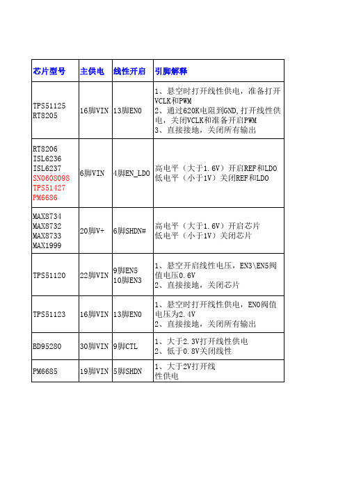
先有LDO5,给VCC供电(根据典型应用图判断) VCC有电后,再产生REF(根据内部框图判断) REF稳定后,再产生LDO3(根据引脚定义判断)
先有VREG5,再给V5FILT供电(根据典型应用图 判断) V5FILT正常后,再产生VREF2(根据内部框图判 断)
1、大于2V打开线 性供电
常用待机
常用待机芯片
PWM开启 引脚解释
1脚 ENTRIP1 2脚 ENTRIP2
通道1和通道2的开启和过流设定脚 1、直接接地,关闭PWM 2、通过电阻到地,作为电流极限设定
高电平开启(大于2.5V),低电平关闭 14脚EN1 (小于0.8V),当EN1连接REF时,PWM1会 27脚EN2 在PWM2稳定后延时开启,当EN2连接到REF
6脚VIN
4脚EN_LDO
高电平(大于1.6V)开启REF和LDO 低电平(小于1V)关闭REF和LDO
MAX8734 MAX8732 MAX8733 MAX1999
20脚V+
6脚SHDN#
高电平(大于1.6V)开启芯片 低电平(小于1V)关闭芯片
TPS51120
22脚VIN
9脚EN5 10脚EN3
时,PWM2会在PWM1稳定后延时开启
3脚ON3 4脚ON5
高电平开启(大于2.4V),低电平关闭 (低于0.8V),把ON3接REF,3.3V的PWM 会在5V的PWM稳定后延时启动
12脚EN2 29脚EN1
高电平(大于2.7V)直接开启 大于0.9V时会延时开启 低电平(小于0.5V)关闭
18脚ENC
笔记本常用供电芯片大全

笔记本常用供电芯片大全线性稳压块:2951、LP2951、m5236、2950、AAT3200、AAT3680、AME8824、AMS1505、APL5912、APL5913、G9338、SC1565、MAX8863、MIC5205、SI91 83、开机芯片:东芝TMP87PM48U、TMP48U、TMP87PH48UIBM:TB6805F、TB6806F、TB6807F TB6808F、TB62501F、、BD4175KV、I/O芯片:PC97338、PC87391、PC87392、pc87393、SMSC系列:FDC37N869、FDC37N958、FDC37N972、LPC47N227/217、LPC47N252 LPC47N253、LPC47N254、LPC47N354、LPC47 N267键盘芯片:H8C/2471、H8/3434、H8/3431、H8S/2116V、PC87541 PC87570、PC87591 PC87594 PC97551 PC97554键盘芯片:具有开机功能:H8/3434、H8/3437、H8/2147、H8/2149、H8/2161、H 8/2168、PC87570、PC87591、H8S/XXX 、M38857、M38867、M38869系统供电芯片:ISL6228 ISL6232、MAX1630 MAX1631、MAX1632、MAX1633、MAX1634、MAX1635、MAX17003 E、MAX1901、MAX1902、MAX1904、MAX1977、MAX1999、MAX785、MAX786、MAX8734、LTC1628、LT3728L、LT3728LX、SB3052、SC1402、SC1403、SC1404、SC2450、TPS51020、TPS51120〈MAX1631、MAX1634、MAX1904 可互换〉〈MAX1632、MAX1635、MAX1902 可互换〉〈MAX786、SB3052 可互换_老机型〉〈MAX8734、MAX1999可互换〉SC1402 (与MAX1632一样)IBM R40用LTC1628(与MAX1632差不多)索尼常用MAX785(奔2机器)辅助供电芯片:ADP3160、ADP3167、ADP3168、APW7057、APW7060、ISL6224、ISL6225、ISL6227、IPM6220A、MAXl540、MAXl541、MAX1623、MAX1626、MAX1627、MAX1644、MAX1710、MAX1711、MAXl712、MAX1714、MAX1715、MAX1717、MAX1718、MAX1809、MAX1844、MAX1845、MAX1992、MAXl993、MAX8505、MAX8550、MAX8632、MAX8743、MAX8794、SC1470、SC1474、SC1476、SC1485、SC1486、SCl486A、SC470、SI786LG、G2996、SWC1486、TPS51116、TPS51117、TPS51120、TPS51124、TPS54610、TPS54672、CPU供电芯片:ADP3166、ADP3170、ADP3180、ADP3181、ADP3203、ADP3421、AIC1567、ISL6215、ISL6218、ISL6223、ISL6227、ISL6260、ISL6262、LTC1436、LTC1736、LTC1709、LTC3716、LTC3735、MAX1532、MAX1710、MAX1711、MAX1712、MAX1714、MAX1717、MAX1718、MAX1830、MAXl831、MAX1897、MAX1907、MAX1987、MAX1988、MAX798、MAX8760、MAX8770、MAX8771、MAX8774、MAX8736SC451、SC452、SC1474、SC1476、供电芯片搭配使用:ADP3203/ADP3415、ADP3205+ADP3415、ADP3410+ADP3421、ADP3410+ADP3422、ADP3207+ADP3419、ADP3208+ADP3419电池充/放电控制芯片:AAI3680、ADP3801、ADP3806BQ24700、BQ2470l、BQ24702、BQ24703、DS2770、ISL6251、M61040FP、MAXl644 MAX1645、MAX1647、MAX1648、MAX745、MAX1736 MAX1772、M AX1773、MAX1870 MAX1873、MAX1908、MAX1909、MAX745、MAX8724、M AX8725、MAX8765、MB3878、MB3879、MB3887、MB39A126PFV、LT1505G、LTl505、LTC4008、TC490/591、TL494、TL594、OZ983、OZ985、笔记本电池电量检测芯片:BQ2040、BQ2060CPU温度控制芯片:MAX1617、MAX1020A、AD1020、AD1021、AD1030、AD103 0A、AD1031、CM8500、MAX1989、AD1020A、MAX6654、ADM1032、G781、L M26、网卡芯片:RTL8100、RTL8139、Intel-DA82562ET、RC82540、3COM、BCM440、BCM5702KBGA、88E8001、88E8055、82562EZ网卡隔离器:LF8423、LF-H80P、H-0023、H0024/42、H0019、ATPL-119(内部是线圈,非电路)声卡芯片:ES1921、ESS1980S、STAC9704、AU8810、4299-JQ、4297-JQ、AD1885、AD1984、8552TS、8542TS、CS4239-KQ、AD1981、AD19 81B、ADl888、ADl981、AD1986、ALC200、ALC201A、ALC202、ALC203、ALC258、ALC262、ALC655、ALC658、ALC660、ALC861、ALC880、ALC883、CMl9738、CS4205、CX20468、CX20549、CX20561 PT2353、(没声音,杂音,声小,查功放芯片)(开机时,没有声音,无声卡设备,查声卡芯片)音频功放芯片:APA2020、TPA0142、TPA0312、TPA6017、TPA0202、LM4835、L M4838、LM4861、LM4863、LM4880、LM4881、LM4882、LM4911、MAX9710、MAX9750、MAX9751、MAX9755、MA X9789、MAX9790、ESS1980S、8552TS、8542TS、TPA0302、AU8810 、BA7786、AN1294、AN12941、AN12942B、AN12943、G1420、PC卡信号芯片:R5C551、R5C552、R5C476、R54472、R5C593、SN0301520、P CIXXX、PC卡供电芯片:TPS2205、TPS2206、TPS2216、TPS2211、TPS2224、PU2211、M2562A、M2563A、M2564A、OZ2206、超级I/O:PC8394TIO芯片:PC系列:PC87591S(VPCQ01)、PC 87591L(VPC01)、PC97317IBWPC87393 VGJ、PC87591E-VLB、PC87591E (-VPCI01)/(VPCQ01)、PC97551-VP C、PC87570-ICC/VPC、PC87391VGJ、PC8394T、PC87392、PC87541L、PC87541VPC87591E-VLB、TB系列:TB62501F、TB62506F、TB6808F、ENE系列:KB3910QB0、KB910SFC1、KB3910SF、KB910QF、KB910QB4、KB9 10LQF、KB910LQFA1其它系列:IT8510E、PS5130、W83L950D、LPC47N249-AQQ、PCI4510、LPC47 N253-AQQ、LPC47N250-SD、LPC47N252-SG、LPC47N254-AQQ、(1)管理串口、并口、软驱、I/O:PC97338、MB87392、(2)管理键盘、鼠标、且带开机功能:H8/3437、H8。
中电熊猫彩电机器机芯及进入工厂模式一览表
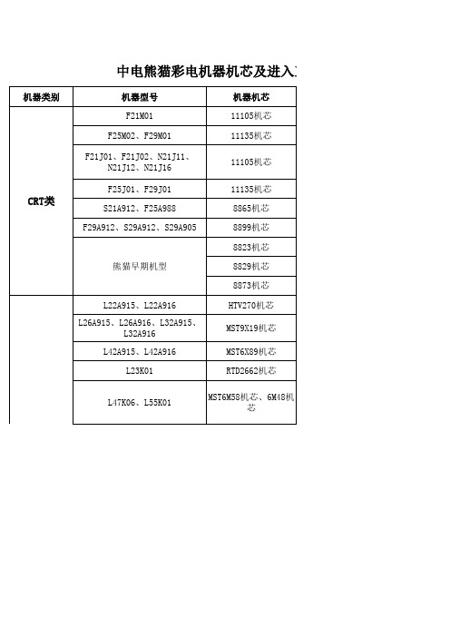
LE22A11、LE24A11、LE26A11、 LE32A11 LE19K11、LE22K11、LE23K11、 LE32K11 LED类 LE19M16、LE22M16、LE24M16、 LE26M16 LE26M18、LE32M18、LE32M16 LE26J12、LE32J12、LE42J12 PDP 触摸屏多媒体 一体机 P50H01、P50H01A、P50H01D
CRT类
S21A912、F25A988 F29A912、S29A912、S29A905
L26K06、L32K01、L32K06、 L37K01、L37K06、L42K01、 L42K06
MST6M16机芯、 RTD2674机芯
L22M01、L26M01
719机芯
L22M02、L24M02、L26M02 L32M02、L32M03 L32M03H、L42M03H
制表日期:2011-06-02
Hale Waihona Puke 中电熊猫彩电机器机芯及进入工厂模式方法一览表
机器类别 机器型号 F21M01 F25M02、F29M01 F21J01、F21J02、N21J11、 N21J12、N21J16 F25J01、F29J01 机器机芯 11105机芯 11135机芯 11105机芯 11135机芯 8865机芯 8899机芯 8823机芯 熊猫早期机型 8829机芯 8873机芯 L22A915、L22A916 L26A915、L26A916、L32A915、 L32A916 L42A915、L42A916 L23K01 L47K06、L55K01 HTV270机芯 MST9X19机芯 MST6X89机芯 RTD2662机芯 MST6M58机芯、6M48机 芯
HX6201机芯
W78E58B中文资料
8.3.1 时钟输入波形...................................................................................................................... 25 8.3.2 程序读取周期...................................................................................................................... 26 8.3.3 数据读取周期...................................................................................................................... 26 8.3.4 数据写周期.......................................................................................................................... 27 8.3.5 端口访问周期...................................................................................................................... 27
CD74HCT390M96,CD74HCT390M96E4,CD74HC390M96E4,CD74HC390M96G4,CD74HCT390E, 规格书,Datasheet 资料

16 Ld SOIC
CD74HC390M96
-55 to 125
16 Ld SOIC
CD74HCT390E
-55 to 125
16 Ld PDIP
CD74HCT390M
-55 to 125
16 Ld SOIC
CD74HCT390MT
-55 to 125
16 Ld SOIC
CD74HCT390M96
-55 to 125
73
Maximum Junction Temperature . . . . . . . . . . . . . . . . . . . . . . . 150oC
Maximum Storage Temperature Range . . . . . . . . . .-65oC to 150oC
Maximum Lead Temperature (Soldering 10s) . . . . . . . . . . . . . 300oC
For VI < -0.5V or VI > VCC + 0.5V . . . . . . . . . . . . . . . . . . . . . .±20mA DC Output Diode Current, IOK
For VO < -0.5V or VO > VCC + 0.5V . . . . . . . . . . . . . . . . . . . .±20mA DC Output Source or Sink Current per Output Pin, IO
3 (13) nQ0
4 (12) nCP1
GND = 8 VCC = 16
÷5
CD4069B-V21无线充电器用
-1
-
输出端流出电 2.5 0,5 5
-2 -1.8 -1.3 -1.15 -1.6
-3.2
IOH 流
9.5 0,10 10 1.6 1.5 -1.1 -0.9 -1.3
-2.6
mA
-
13.5 0,15 15 -4.2 -4 -2.8 -2.4 -3.4
-6.8
-
- 0,5 5 0.05 -
0 0.05
输出低电平电
VOL 压
- 0,10 10 0.05 -
0 0.05
V
- 0,15 15 0.05 -
0 0.05
- 0,5 5 4.95 4.95 5
-
输出高电平电
VOH 压
- 0,10 10 9.95 9.95 10
-
- 0,15 15 14.95 14.95 15
-
4.5
-
5
1
-
输入低电平电
VIL 压(最大)
0.4 0,5 5 0.64 0.61 0.42 0.36 0.51
1
输出端灌入电
IOL 流
0.5 0,10 10 1.6 1.5 1.1 0.9 1.3
2.6
1.5 0,15 15 4.2
4
2.8 2.4
3.4
6.8
-
-
mA
-
4.6 0,5 5 0.64 -0.61 -0.42 -0.36 -0.51
CD4069B
CMOS 六反相器
概述
(最高额定电压 20V)
CD4069B 由六个 CMOS 反相器电路组成。可用于所有的通用反相器应用场合, 由于芯片内部采用单级门,因此特别适用于构成 CMOS 晶体及 RC 振荡器,也可以 用来构成简单的自偏置对称放大器。
4069电路

CD4069组成的轻触及电子开关电路原理图CD4069组成的轻触及电子开关电路原理图这个电路可以做为一般ON-OFF 开关的替代品,为一双稳开关控制电路,CD4069为一CMOS 反向器IC,未使用的反向器输入端接地,未使用的反向器输出端全部空接,当按第一次S1 开关时继电器动作,再按一次时继电器释放。
IC1 MC14069 (or 4069) ,是一般用途常用的MOS 反向器,操作的电压可从3V~18V,但大部份的运用都使用于5~15V 的供电电压,电路中的D1 作用是在保护电路免受继电器回压的损坏,注意不要接反,否则动作时造成短路,继电器是不会动作的。
继电器规格随使用电源变化,9V 时可使用6V 继电器,9V 以上供电电压可使用12V继电器。
但也要注意使用12V 供电时R4(LED 的限流电阻)要改为390姆.MN4069UB代换型号:CD4069BE CD4069C CD4069CJ CD4069CN CD4069M CD4069MJ CD4069N CD4069UBD 4069UBDC 4069UBDM 4069UBPC 46-13319-3 51-90433A10 51X90507A99 6122500001 8-759-240-69 8-759-904-69 905-260 07-28816-86 144971 152935 207890 34069PC轻触电子开关电路图-电路图-维修原理图-线路图-主板图纸-电子元件图纸这个电路可以做为一般ON-OFF 开关的替代品,为一双稳开关控制电路,CD4069为一CMOS 反向器IC,未使用的反向器输入端接地,未使用的反向器输出端全部空接,当按第一次S1 开关时继电器动作,再按一次时继电器释放。
IC1 MC14069 (or 4069) ,是一般用途常用的CMOS 反向器,操作的电压可从3V~18V,但大部份的运用都使用于5~15V 的供电电压,电路中的D1 作用是在保护电路免受继电器回压的损坏,注意不要接反,否则动作时造成短路,继电器是不会动作的。
电脑维修常用电源管理芯片代换型号

CET6030L、3055
电压稳压器:
1084、1117
电容:
6.3V(10V)3300μf、6.3V(10V)2200μf、6.3V(10V)1500μf
RT9229-----H*6019B
RT9230------H*6020
RT9231-------H*6021
RT9231A----H*6021A
RT9238------ ISL6524
RT9239-------H*6012
370的将VSS、VIDO、VSS(VID4)、VID3连上。
462的将VID0、VID1、VID2、VID4与地连上,地线在右上角第六行往里数第5针。
常用电源管理芯片电源管理芯片电源芯片u盘芯片型号怎么看电源线型号开关电源芯片常用塔吊型号led芯片型号常用运放型号常用铝合金型号2:04来源:未知作者:飞鸟恋鱼点击:162次
电脑维修常用电源管理芯片代换型号如下: RT9221----SC1164 RT9222----SC1165 RT9223----SC1153 RT9224----H*6004B RT9224B--CL6911E RT9224C--H*6004D RT9224E--H*6004E RT9227A---H*6016 RT9228-----H*6018B RT9229-----H*6019B RT9230------H*6020 RT9231
478的将第一排第一针(VSS)与VID4、VID3连上就可以了。
主板维修常备的芯片有如下种类:
电源IC:RT9231/A、H*6021CB/ACB、H*6301CB、RT9241、SC1164CSW、SC1153CSW、H*6602CB、KA7500B、IRU3013
CD4069UBE中文资料

Data sheet acquired from Harris Semiconductor SCHS054IMPORTANT NOTICETexas Instruments and its subsidiaries (TI) reserve the right to make changes to their products or to discontinue any product or service without notice, and advise customers to obtain the latest version of relevant information to verify, before placing orders, that information being relied on is current and complete. All products are sold subject to the terms and conditions of sale supplied at the time of order acknowledgement, including those pertaining to warranty, patent infringement, and limitation of liability.TI warrants performance of its semiconductor products to the specifications applicable at the time of sale in accordance with TI’s standard warranty. Testing and other quality control techniques are utilized to the extent TI deems necessary to support this warranty. Specific testing of all parameters of each device is not necessarily performed, except those mandated by government requirements.CERTAIN APPLICATIONS USING SEMICONDUCTOR PRODUCTS MAY INVOLVE POTENTIAL RISKS OF DEATH, PERSONAL INJURY, OR SEVERE PROPERTY OR ENVIRONMENTAL DAMAGE (“CRITICAL APPLICATIONS”). TI SEMICONDUCTOR PRODUCTS ARE NOT DESIGNED, AUTHORIZED, OR WARRANTED TO BE SUITABLE FOR USE IN LIFE-SUPPORT DEVICES OR SYSTEMS OR OTHER CRITICAL APPLICATIONS. INCLUSION OF TI PRODUCTS IN SUCH APPLICATIONS IS UNDERSTOOD TO BE FULLY AT THE CUSTOMER’S RISK.In order to minimize risks associated with the customer’s applications, adequate design and operating safeguards must be provided by the customer to minimize inherent or procedural hazards.TI assumes no liability for applications assistance or customer product design. TI does not warrant or represent that any license, either express or implied, is granted under any patent right, copyright, mask work right, or other intellectual property right of TI covering or relating to any combination, machine, or process in which such semiconductor products or services might be or are used. TI’s publication of information regarding any third party’s products or services does not constitute TI’s approval, warranty or endorsement thereof.Copyright © 1998, Texas Instruments Incorporated。
多种电源管理芯片代换

1200AP40 1200AP60、1203P60200D6、203D6 DAP8A 可互代203D6/1203P6 DAP8A2S0680 2S08803S0680 3S08805S0765 DP104、DP7048S0765C DP704加24V的稳压二极管ACT4060 ZA3020LV/MP1410/MP9141ACT4065 ZA3020/MP1580ACT4070 ZA3030/MP1583/MP1591MP1593/MP1430 ACT6311 LT1937ACT6906 LTC3406/AT1366/MP2104AMC2576 LM2576AMC2596 LM2596AMC3100 LTC3406/AT1366/MP2104AMC34063A AMC34063AMC7660 AJC1564AP8012 VIPer12AAP8022 VIPer22ADAP02 可用SG5841 /SG6841代换DAP02ALSZ SG6841DAP02ALSZ SG6841DAP7A、DP8A 203D6、1203P6DH321、DL321 Q100、DM0265RDM0465R DM/CM0565RDM0465R/DM0565R 用cm0565r代换(取掉4脚的稳压二极管)DP104 5S0765DP704 5S0765DP706 5S0765DP804 DP904FAN7601 LAF0001LD7552 可用SG6841代(改4脚电阻)LD7575PS 203D6改1脚100K电阻为24KOB2268CP OB2269CPOB2268CP SG6841改4脚100K电阻为20-47KOCP1451 TL1451/BA9741/SP9741/AP200OCP2150 LTC3406/AT1366/MP2104OCP2160 LTC3407OCP2576 LM2576OCP3601 MB3800OCP5001 TL5001OMC2596 LM2596/AP1501PT1301 RJ9266PT4101 AJC1648/MP3202PT4102 LT1937/AJC1896/AP1522/RJ9271/MP1540SG5841SZ SG6841DZ/SG6841DSM9621 RJ9621/AJC1642SP1937 LT1937/AJC1896/AP1522/RJ9271/MP1540STR-G5643D STR-G5653D、STR-G8653DTEA1507 TEA1533TEA1530 TEA1532对应引脚功能接入THX202H TFC719THX203H TFC718STOP246Y TOP247YVA7910 MAX1674/75 L6920 AJC1610VIPer12A VIPer22A[audio01]ICE2A165(1A/650V.31W);ICE2A265(2A/650V.52W);ICE2B0565(0.5A/650V.23W):ICE2B165(1A/650V.31W);ICE2B265(2A/650V.52W);ICE2A180(1A/800V.29W);ICE2A280(2A/800.50W).KA5H0365R, KA5M0365R, KA5L0365R, KA5M0365RN# u) t! u1 W1 B) R, PKA5L0365RN, KA5H0380R, KA5M0380R, KA5L0380R1、KA5Q1265RF/RT(大小两种体积)、KA5Q0765、FSCQ1265RT、KACQ1265RF、FSCQ0765RT、FSCQ1565Q这是一类的,这些型号的引脚功能全都一样,只是输出功率不一样。
CD4049中文资料

CD4049中文资料CD4049 六反相缓冲器/转换器.,CD4049是六反相缓冲器,具有仅用一电源电压(VCC)进行逻辑电平转换的特征。
用作逻辑电平转换时,输入高电平电压(V IH)超过电源电压V CD。
该器件主要用作COS/MOS到DTL/TTL的转换器,能直接驱动两个DTL/TTL负载。
CD4049可替换CD4009,因为CD4049仅需要一电源电压,可取代CD4009用于反相器、电源驱动器或逻辑电平转换器。
CD4049与CD4009引出端排列一致,16引出端是空脚,与内部电路无连接。
若使用时不要求高的漏电流或电压转换,推荐使用CD4049六反相器。
CD4049引脚图:CD4049 内部图Supply Voltage电源电压(VDD) -0.5V to +18V Input Voltage输入电压(VIN) -0.5V to +18VVoltage at Any Output Pin (VOUT)电压在任何输出引脚(输出电压) -0.5V to VDD + 0.5V Storage Temperature Range储存温度范围 (TS) -65? to +150?Dual-In-Line 普通双列封装 700 mW Small Outline 小外形封装 500 mW 焊接温度(TL)(焊接10秒) 260?Supply Voltage电源电压(VDD) 3V to 15V Input Voltage输入电压 (VIN)0V to 15V Voltage at Any Output Pin (VOUT)电压在任何输出引脚(输出电压)0 to VDDCD4049UBC, CD4050BC -40? to +85?-40? +25? +85?VDD = 5V 4 0.03 4.0 30Quiescent Device IDD VDD = 10V 8 0.05 8.0 60 μA Current静态电流VDD = 15V 16 0.07 16.0 120μLOW Level OutputVDD = 5V 0.05 0 0.05 0.05 Voltage 输出低VOLVDD = 10V 0.05 0 0.05 0.05 V 电平电压VDD = 15V 0.05 0 0.05 0.05μHIGH LevelVDD = 5V 4.95 4.95 5 4.95 Output Voltage VOHVDD = 10V 9.95 9.95 10 9.95 V 输出高电平电压VDD = 15V 14.95 14.95 15 14.95μ LOW Level InputVDD =5V, VO =0.5V 1.5 2.25 1.5 1.5 Voltage 输入低VIL 电平电压 VDD = 10V, VO =1V 3.0 4.5 3.0 3.0 V(CD4050BC Only) VDD =15V, VO=1.5V 4.0 6.75 4.0 4.0μ LOW Level InputVDD=5V, VO = 4.5V 1.0 1.5 1.0 1.0 Voltage 输入低VIL 电平电压 VDD=10V, VO = 9V 2.0 2.5 2.0 2.0 V(CD4049UBC Only) VDD=15V,VO= 13.5V 3.0 3.5 3.0 3.0μ HIGH Level InputVDD =5V, VO =4.5V 3.5 3.5 2.75 3.5 Voltage 输入高VIH 电平电压VDD =10V, VO =9V 7.0 7.0 5.5 7.0 V (CD4050BC Only) VDD=15V, VO=13.5V 11.011.0 8.25 11.0μ HIGH Level InputVDD =5V, VO =0.5V 4.0 4.0 3.5 4.0 Voltage 输入高VIH 电平电压VDD = 10V, VO =1V 8.0 8.0 7.5 8.0 V (CD4049UBC Only) VDD=15V, VO =1.5V 12.0 12.0 11.5 12.0LOW Level OutputVDD =5V, VO =0.4V 4.6 4.0 5 3.2 Current 输出低IOL 电平电流 (Note VDD =10V, VO=0.5V 9.8 8.5 12 6.8 mA 4) VDD=15V, VO =1.5V 29 25 40 20 HIGH LevelVDD =5V,VO =4.6V -1.0 -0.9 -1.6 -0.72 Output Current IOH 输出高电平电流 VDD =10V,VO=9.5V -2.1 -1.9 -3.6 -1.5 mA (Note 4) VDD=15V,VO=13.5V -7.1 -6.2 -12 -5-5 VDD= 15V, VIN=0V -0.3 -0.3 -10 -1.0 Input Current 输IIN μA 入电流 VDD =15V, VIN=15V 0.3 0.3 10-5 1.0VDD = 5V 30 65 Propagation Delay Time HIGH-to-LOW Level 传播延迟高tPHL VDD = 10V 20 40 ns 到低VDD = 15V 15 30VDD = 5V 45 85 Propagation Delay Time LOW-to-HIGH Level 传播延迟低tPLH VDD = 10V 25 45 ns 到高VDD = 15V 20 35VDD = 5V 30 60tTHL Transition Time HIGH-to-LOW Level 过渡时间高到低 VDD = 10V 20 40 nsVDD = 15V 15 30VDD = 5V 60 120tTLH Transition Time LOW-to-HIGH Level 过渡时间低到高 VDD = 10V 30 55 nsVDD = 15V 25 45CIN Input Capacitance 输入电容 Any Input 15 22.5 pFCD4049交流特性波形图。
cd4069工作原理
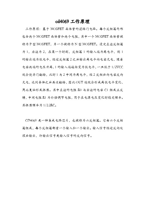
cd4069工作原理
工作原理:基于MOSFET晶体管的逻辑门电路。
每个反相器内部包含两个MOSFET晶体管和两个电阻,其中一个MOSFET晶体管被称为P型MOSFET,另一个被称为N型MOSFET。
设定左边反相器为1,右边为2,在某一个时刻,反相器1的输入端为高电平,则1的输出端为低电平,经过反相器2之后输出高电平向电容充电,随着电容两端的电压升高,1的输入端逐渐变为低电平,一旦低于1/2VCC 就会使非门翻转,此时1与2中间为高电平,经2反相后向电容反向充电,达到条件之后再次翻转,因此OUT端就会形成高低电平变化,周而复始形成振荡。
其中左边的电阻R0与右边的电容C1组成正反馈,中间电阻R1为补偿调节电阻,用于在电源电压变化时稳定频率。
其振荡频率为1/2.2RC。
CD4069是一种集成电路芯片,也被称为六反相器。
它由六个反相器组成,每个反相器都有一个输入和一个输出。
输入信号经过反向处理后输出,即输出信号是输入信号的反向信号。
CD4069逻辑功能及引脚介绍

CD4069逻辑功能及引脚如图2a所示,其中非门F1、F2和外接电阻R2、R3、电容C4构成多谐振荡器,产生约3Hz的脉冲方波,供给CD4017作计数脉冲和CD40174作移位脉冲。
R3、C4为振荡定时元件,调节这两个元件可改变振荡信号频率,从而控制彩灯色彩的流动速度,以呈现各种不同的视觉效果。
另外,CD4069的非门3还用作CD40174复位信号的倒相器。
CD4069为CMOS数字集成电路,是一种高输入阻抗器件,容易受外界干扰造成逻辑混乱或出现感应静电而击穿场效应管的栅极。
虽然器件内部输入端设置了保护电路,但它们吸收瞬变能量有限,过大的瞬变信号和过高的静电电压将使保护电路失去作用,因此,CD4069中未使用的非门F4、F5、F6的输入端{9}、{11}、{13}脚均接到Vss接地端,以作保护。
CD4069多谐振荡器输出端{4}脚送出的脉冲串,一路直接送入CD4017的计数脉冲输入端{14}脚。
CD4017为十进制计数/时序分配器,用于产生CD4066模拟开关切换的控制信号。
其引脚功能如图2b所示。
Cr为复位端,当Cr端输入高电平时、计数器置零态。
CD4017具有自动启动功能,即在电路进入无效状态时,在计数脉冲作用下,最多经过两个时钟周期就能回到正常循环圈中,因此本控制器的CD4017未设置加电复位电路。
Co为进位输出端,当计数满10个时钟脉冲时输出一个正脉冲。
CD4017有CL和EN两个计数输入端,CL端为脉冲上升沿触发端,若计数脉冲从CL端输入,则EN端应接低电平;EN端为脉冲下降沿触发端,若计数脉冲从EN端输入,则CL端应接高电平,否则禁止输入计数脉冲。
取自CD4069的计数脉冲从其CL端{14}脚输入,故EN端{13}脚接地。
Y0~Y9为计数器的十个输出端,输出端送出的脉冲方波通过隔离二极管VD3~VD12连接成两路控制信号,加到模拟开关CD4066。
当第一个计数脉冲到来时,CD4017内电路翻转,{3}脚Y0呈高电平,经二极管VD5加到CD4066{12}脚。
东芝2010电源故障代码

东芝2010电源故障代码
1. 由一系列代码(不含“00”和“FF”)到“FF”或“00”,则东芝2010电源自检已通过,OK。
2. 出“00”,且不变码,则为主板没有运行,查东芝2010电源坏否、东芝2010电源跳线、或东芝2010电源设置正确否、东芝2010电源处有否发霉?
3. 如果您在东芝2010电源中设置为不提示错,则遇到非致命性故障时,诊断卡不会停下来而接着往后走一直到“00”,解决方法为更改东芝2010电源设置为提示所有错误再开机,这时若有非致命故障则停住,再根据代码排错。
0A
使东芝2010电源接口作初始准备。
查与显卡有关的电路。
0B
测试东芝2010电源DMA通道0。
查主板中键盘控制电路及键盘中的控制电路。
0C
测试东芝2010电源。
查键盘中的控制电路。
0D
1A
测试东芝2010电源的中断控制器(8259)屏蔽位。
查主板中的8259芯片。
1B
测试东芝2010电源电平。
查主板中电池有电否,有些板的电池装在CMOS模块里面,可拆下上盖更换电池。
1C
测试东芝2010电源检查总和。
查主板中东芝2010电源芯片及其电路。
1D
调定东芝2010电源的配置。
查主板中东芝2010电源芯片。
1E
测定系统存储器的大小,并且把它和东芝2010电源值比较。
查主板中的东芝2010电源及主板中的内存。
1F
测试东芝2010电源存储器至最高640K。
查主板中的内存条或内存芯片。
- 1、下载文档前请自行甄别文档内容的完整性,平台不提供额外的编辑、内容补充、找答案等附加服务。
- 2、"仅部分预览"的文档,不可在线预览部分如存在完整性等问题,可反馈申请退款(可完整预览的文档不适用该条件!)。
- 3、如文档侵犯您的权益,请联系客服反馈,我们会尽快为您处理(人工客服工作时间:9:00-18:30)。
Data sheet acquired from Harris SemiconductorSCHS062B – Revised July 2003The CD4089B types are supplied in 16-leadhermetic dual-in-line ceramic packages (F3Asuffix), 16-lead dual-in-line plastic packages (Esuffix), 16-lead small-outline packages (NSRsuffix), and 16-lead thin shrink small-outlinepackages (PW and PWR suffixes).Copyright 2003, Texas Instruments IncorporatedPACKAGING INFORMATIONOrderable DeviceStatus (1)Package Type Package DrawingPins Package Qty Eco Plan (2)Lead/Ball Finish MSL Peak Temp (3)CD4089BE ACTIVE PDIP N 1625Pb-Free (RoHS)CU NIPDAU N /A for Pkg Type CD4089BEE4ACTIVE PDIP N 1625Pb-Free (RoHS)CU NIPDAUN /A for Pkg Type CD4089BF3A ACTIVE CDIP J 161TBDA42N /A for Pkg Type CD4089BNSR ACTIVE SO NS 162000Green (RoHS &no Sb/Br)CU NIPDAU Level-1-260C-UNLIM CD4089BNSRE4ACTIVE SO NS 162000Green (RoHS &no Sb/Br)CU NIPDAU Level-1-260C-UNLIM CD4089BNSRG4ACTIVE SO NS 162000Green (RoHS &no Sb/Br)CU NIPDAU Level-1-260C-UNLIM CD4089BPWR ACTIVE TSSOP PW 162000Green (RoHS &no Sb/Br)CU NIPDAU Level-1-260C-UNLIM CD4089BPWRE4ACTIVE TSSOP PW 162000Green (RoHS &no Sb/Br)CU NIPDAU Level-1-260C-UNLIM CD4089BPWRG4ACTIVETSSOPPW162000Green (RoHS &no Sb/Br)CU NIPDAULevel-1-260C-UNLIM(1)The marketing status values are defined as follows:ACTIVE:Product device recommended for new designs.LIFEBUY:TI has announced that the device will be discontinued,and a lifetime-buy period is in effect.NRND:Not recommended for new designs.Device is in production to support existing customers,but TI does not recommend using this part in a new design.PREVIEW:Device has been announced but is not in production.Samples may or may not be available.OBSOLETE:TI has discontinued the production of the device.(2)Eco Plan -The planned eco-friendly classification:Pb-Free (RoHS),Pb-Free (RoHS Exempt),or Green (RoHS &no Sb/Br)-please check /productcontent for the latest availability information and additional product content details.TBD:The Pb-Free/Green conversion plan has not been defined.Pb-Free (RoHS):TI's terms "Lead-Free"or "Pb-Free"mean semiconductor products that are compatible with the current RoHS requirements for all 6substances,including the requirement that lead not exceed 0.1%by weight in homogeneous materials.Where designed to be soldered at high temperatures,TI Pb-Free products are suitable for use in specified lead-free processes.Pb-Free (RoHS Exempt):This component has a RoHS exemptionfor either 1)lead-based flip-chip solder bumps used between the die and package,or 2)lead-based die adhesive used between the die and leadframe.The component is otherwise considered Pb-Free (RoHS compatible)as defined above.Green (RoHS &no Sb/Br):TI defines "Green"to mean Pb-Free (RoHS compatible),and free of Bromine (Br)and Antimony (Sb)based flame retardants (Br or Sb do not exceed 0.1%by weight in homogeneous material)(3)MSL,Peak Temp.--The Moisture Sensitivity Level rating according to the JEDEC industry standard classifications,and peak solder temperature.Important Information and Disclaimer:The information provided on this page represents TI's knowledge and belief as of the date that it is provided.TI bases its knowledge and belief on information provided by third parties,and makes no representation or warranty as to the accuracy of such information.Efforts are underway to better integrate information from third parties.TI has taken and continues to take reasonable steps to provide representative and accurate information but may not have conducted destructive testing or chemical analysis on incoming materials and chemicals.TI and TI suppliers consider certain information to be proprietary,and thus CAS numbers and other limited information may not be available for release.In no event shall TI's liability arising out of such information exceed the total purchase price of the TI part(s)at issue in this document sold by TI to Customer on an annual basis.PACKAGE OPTION ADDENDUM11-Nov-2009TAPE AND REEL INFORMATION*All dimensions are nominalDevicePackage Type Package Drawing Pins SPQReel Diameter (mm)Reel Width W1(mm)A0(mm)B0(mm)K0(mm)P1(mm)W (mm)Pin1Quadrant CD4089BNSR SO NS 162000330.016.48.210.5 2.512.016.0Q1CD4089BPWRTSSOPPW162000330.012.46.95.61.68.012.0Q1*All dimensions are nominalDevice Package Type Package Drawing Pins SPQ Length(mm)Width(mm)Height(mm) CD4089BNSR SO NS162000367.0367.038.0CD4089BPWR TSSOP PW162000367.0367.035.0分销商库存信息:TICD4089BPWR CD4089BE CD4089BPWRE4 CD4089BPWRG4CD4089BNSR CD4089BNSRE4 CD4089BNSRG4CD4089BEE4CD4089BPW CD4089BPWE4CD4089BPWG4。
