OPV315YF中文资料
Philips 150S5FS 15 英寸 LCD 显示器说明书

15 inch LCD MonitorPicture/ DisplayCommercial Specifications•LCD Panel Type 1024 x 768 pixels,Anti-glare Polarizer,RGB Vertical Stripe •Panel Size 15"/ 38 cm•Effective Viewing Area 304.1 x 228.1 mm •Pixel Pitch 0.297 x 0.297 mm •Brightness (nits) 250•Contrast Ratio 400:1•Display Colors 16 M•Viewing Angle (C/R > 5) - Horizontal : 160°- Vertical : 140°• Response Time 16 ms• White Chromaticity, 6500º K x = 0.313 / y = 0.329• White Chromaticity, 9300º K x = 0.283 / y = 0.297• Maximum Resolution 1024 x 768 @ 75Hz• Recommended Resolution 1024 x 768 @ 60Hz• Factory Preset Modes 14 modes• User Definable Modes 16 modes• Horizontal Scanning Frequency 30 - 61 KHz• Refresh Rate (V) 56 - 76 Hz• sRGB YesConnectivity• Signal Input Analog (VGA) Convenience• Convenience Enhancements On-screen Display,SmartManage• Monitor Controls Auto, Brightness control,Left/Right, Menu (OK),Power On/Off, Up/Down • OSD Languages English, French, German,Italian, Simplified Chinese,Spanish• Other Convenience Features Kensington Lock• Plug & Play Compatibility DDC/CI, sRGB,Windows 98/ME/2000/XP • Regulatory Approvals CE Mark, E2000, EMC,FCC-B, UL, CSA, MPR-II,Low Emission, NUTEK,Energy Star, SEMKO,TCO '03, TCO '99, TUV/GS,TUV Ergo• Tilt -5° to 25°• VESA Mount 100 mm x 100 mm Accessories• User Manual Yes• Included Accessories AC Power Cord, VGA Cable SmartManageA system for monitoring, managing and checking status of display devices as well as delivering remote support to users who experience difficulties all accomplished over a LAN.Lower power consumptionReduction of the electrical power required to operate a device. Kensington anti-theft lockA security device that fixes the monitor in place to prevent theft. Fast response timeThe amount of time it takes for a liquid crystal cell to go from active (black) to inactive (white) and back to active (black) again.It is measured in milliseconds. Lower numbers mean faster transitions and therefore results in fewer visible image artifacts. XGA, 1024 x 768 resolutionFor graphics monitors, the screen resolution signifies the numberof dots (pixels) on the entire screen. For example, a 1024-by-768 pixel screen is capable of displaying 1024 distinct dots on eachof 768 lines, or about 786 thousand pixels. XGA provides resolutions of 640 by 480 or 1024 by 768 pixels. In addition, XGA allows monitors to be non-interlaced. This ensures a better display performance and accurate color display effect.sRGB readyCalibrated RGB that is optimized for the vast majority of computer peripherals, monitors, operating systems and browsers, allowing accurate color mapping with very little data overhead. Embedded power supplyA power adaptor built into the body of a display device that replaces a bulky external power adaptor.VESA mounting holesA unified industry standard for wall mounting IT equipment set by the Video Electronics Standards Association.FlexiHolderA slim groove that improves efficiency by holding reminder notes, documents, name cards, and photos on the top of monitor to be more efficient..Product HighlightsDimensions• Depth (with base) 180 mm• Height (with base) 344 mm• Width (with base) 342 mm• MTBF 50,000 (excl. CCFL40,000) hrs• Relative Humidity 20 % - 80 %• Temperature Range (Operation) 5°C to 40°C• Temperature Range (Storage) -20°C to 60°C • Weight 2.8 kgPower• Complies With E2000, Energy Star,NUTEK• Consumption 17 W (Typical)• Off Mode < 1 W• Power LED Indicator Operation, Green;Stand by/Sleep,Amber• Power Supply Built-in Trademarks owned by Royal Philips Electronics2004 © Royal Philips Electronics - All rights reserved As an Energy Star partner, Philips has determined that this product meets the Energy Star guidelines for energy efficiency.Microsoft and Windows are registered trademarks of Microsoft Corporation.All data subject to change without noticeRelease date: June 2004。
REF615中文版3.0

2. 标准配置
馈线保护测控装置 REF615 有九种可选择的标准配 置。标准配置可通过保护测控装置管理工具 PCM600 中的矩阵或应用配置功能进行更改。此外,PCM600 中 的应用配置功能支持创建多层逻辑,可以使用包括定时 器和触发器在内的多种不同逻辑元件。应用丰富的逻辑 模块组合不同的功能模块,可满足用户不同的应用需 求。
ABB
1YZA000042 版本:F/2010.07.02
ABCDE FG J K - - - - - yyyy - - - - - yyyy - - - - - yyyy - - - - - yyyy - - - - - yyyy - - - - - yyyy - - - - - yyyy yyyyyyy - y - - - - - y - yy - - - - - y - yy - - - - - y - yy - - - - - - -y- - - - - - -y- - - - - - -yyyyyyyyyy yyyyyyyyy yyyyyyyyy yyyyyyyyy ○○○○○○○○○ ○○○○○○○○○ ○○○○○○○○○
Relion® 615 ဣଚ
ઍ၍ԍࢺ֪੦ጎዃREF615 ׂኸళ
馈线保护测控装置 REF615 产品版本:3.0
目录
1. 概述 .............................................................3 2. 标准配置 ......................................................3 3. 保护功能 ......................................................7 4. 应用 ...........................................................14 5. ABB 配电自动化解决方案 .........................17 6. 控制功能 ....................................................19 7. 测量功能 ....................................................19 8. 故障录波 ....................................................19 9. 事件记录 ....................................................20 10. 故障数据记录 .............................................20 11. 断路器监视 .................................................20 12. 跳合闸回路监视 .........................................20 13. 自检功能 ....................................................20 14. VT 熔丝断线监视 .......................................21 15. 电流回路监视 .............................................21
三品变频器主要参数

Pr078 PLC 运转方向
参数值01001010换成十进制 即:01001010B=74 所以参数Pr078=74
Pr079
PLC加减速时间
Pr079=0000000001100011B=99
内控多段速(定时器)
Pr087 Pr088 Pr089 Pr090 Pr091 Pr092 Pr093 Pr094 定时器一 定时器二 定时器三 定时器四 定时器五 定时器六 定时器七 定时器八
运行时间由 Pr087~Pr094 定时器设定,不 用的控制段,定时器设定为零即可 各段速运行方向由 Pr078 (PLC 运转方向) 设定 各段速加减速时间由 Pr079(PLC 加减速时 间)设定
Pr003-Pr007用来确定变频器的V/F曲线, 以应对不同的负载特性
Pr009 频率下限
说明: 频率下限主要防止现场人员的误操作,避 免马达因运转频率过低可能产生的过热或 其他机械故障等。 频率下限的设定必须小 于频率上限的设定值。 (频率上限即Pr007最高操作频率) 类比施耐德变频器SEt-LSP、 SEt-HSP
三品变频器主要参数说明
Pr000
主频率设定
说明: 在运转频率来源设定为面板操作情况下, 频率以 Pr000 设定值运行。 在多段速运行中,主频率为第一段速频率。 在设定为外控多段速运行时,如果把Pr034 设定为1,即外部端子给定时,则第一段速 由外部端子模拟量给定。 主频率的设定受最大操作频率限制。
类比施耐德变频器SEt-JPF、JF2
多功能输入端子设置
三品:端子——功能 施耐德:功能——端子
多功能输出端子设置
输出配置:I-O-AOIt、dO(AOV/AOC) 继电器配置:I-O-r1、r2
433MHz(315MHz)无线接收芯片中文规格书介绍

产品特征●300MHz到440MHz的频率范围●工作电压:2.2V-3.6V●接受灵敏度高:-108dBm●数据传输速率达10kbps(固定模式)●低功耗⏹315MHz下,最大工作电流2.5mA433MHZ下,最大工作电流3.5mA⏹关闭时的电流为0.9uA⏹扫描操作时(10:1任务周期操作)电流为300uA●唤醒输出标记用来启动解码器和微处理器●天线处的射频辐射非常低●集成度高,外部器件需求少应用领域●汽车远程无钥匙进入(RKE)●远程控制●远程风扇和电灯控制●车库门和门禁控制XC4366是一个ASK/OOK(开关键控)的单晶片射频接收集成电路设备。
它是一个真正的“从天线接收到数据输出”的单片电路。
所有的射频和中频的调谐都在集成电路里完成,这样可以无须手动调整并且降低成本。
实现了一个高度可靠且低成本的解决方案。
XC4366是一个采用16引脚封装且功能齐全的芯片,XC4366A/B/C/DL采用了8引脚封装,功能稍有减少。
XC4366提供了两种附加的功能,(1)一个关闭引脚,在任务周期操作时可以用来关闭设备;(2)一个唤醒输出引脚,当接收到射频信号时,它可以提供一个输出标记。
这些特点使得XC4366可以用在低功耗的应用上,比如RKE和远程控制。
XC4366上提供了所有的中频滤波和数据解调滤波器,所以,不需要外部的滤波器了。
四个解调滤波器的带宽可以由用户从外部控制。
XC4366提供了两种工作模式:固定模式(FIX)和扫描模式(SWP)。
在固定模式中,XC4366用作传统的超外差接收器。
在扫描模式下,XC4366在一个较宽的射频范围内进行扫描。
固定模式提供了更有选择性和针对性的工作模式,并且使得XC4366可以与低成本,精确度较低的发射器一起使用。
1.目录1.目录 (2)2.典型的应用 (3)3.订货须知 (4)4.引脚框图 (4)5.引脚的选择性 (5)6.引脚定义 (5)7.极限最大值(注释1) (6)8工作额定值(注释2) (6)9.电气特性 (7)10.功能框图 (9)11.应用说明和功能描述 (9)12.设计步骤 (9)12.1步骤1:选择工作模式 (10)12.2步骤2:选择参考晶振 (10)12.3步骤3.选择CTH电容 (12)12.4步骤4:选择CAGC电容 (13)12.5步骤5:选择解调器的带宽 (14)13.其他应用程序信息 (15)13.1天线阻抗匹配 (15)13.2关机功能 (17)13.3电源旁路电容 (18)13.4可选带通滤波器可增加选择性 (18)13.5数据噪声控制 (18)13.6唤醒功能 (19)14.封装信息 (20)14.1 16引脚的SOP封装 (20)14.2 8引脚的SOP封装 (21)14.3 16引脚的SOP顶层标志 (21)14.4 8引脚的SOP顶层标志 (22)2.典型的应用315MHz 800bps的开关键控接收器433.92MHz 800bps的开关键控接收器3.订货须知4.引脚框图标准的16引脚或者8引脚的封装5.引脚的选择性标准的16引脚允许完整的可配置型的控制。
YPT3变频调速三相异步电动机样本
YPT3系列变频调速三相异步电动机佳木斯电机股份有限公司YPT3系列变频调速三相异步电动机(机座号80mm~355mm)1.概述YPT3系列变频调速三相异步电动机是我公司自行开发设计的产品。
YPT3效率指标符合GB 18613-2012《中小型三相异步电动机能效限定值及能效等级》中的“电动机节能评价值”中的3级效率的规定.本系列电动机机座号范围为80mm~355mm,功率等级和安装尺寸符合GB/T4772.1/IEC 60072-1和GB/T4772.2/ IEC 60072-2标准的规定。
2.产品特点2.1 电动机采用独立通风(冷却方式为IC416)和自扇冷却(冷却方式为IC411)两种通风结构,前者调频范围为0~60Hz,4极以上可扩大调频范围,后者调频范围为35~60Hz。
2.2电动机主接线盒和独立风机的接线盒位于机座的顶部,可以左右出线,满足用户不同出线方式的要求;2.3机座号160及以上电机,可以根据用户需要提供定子测温装置、轴承测温装置、加热器、不停机注排油装置;2.4 机座号225及以上电机,可根据用户需要提供底脚调整螺栓孔;2.5 非轴伸端可安装编码器、测速机等辅助设备。
2.6 接线盒、机座、端盖和风罩的外形美观、样式新颖,并且有利于降噪和通风;2.7 电动机采用热分级为155(F)级绝缘系统,从而延长电机的使用寿命;2.8 电动机工作制为S1;2.9 外壳防护等级为IP55;2.10 如用于各种特殊环境,如:“W”、“TH”、“WTH”、“F1”、“F2”、“WF1”及“WF2”,其中:W为户外防轻腐蚀;TH为湿热;WTH为户外湿热;F1为户内防中等防腐;F2为户内防强腐蚀;WF1为户外防中等腐蚀;WF2为户外防强腐蚀,需在定货时提出。
2.11为了方便连接负载,在电动机轴伸端面均预留有C型中心孔;2.12机座号132及以上在电机机座底部安装有排水阀(安装方式为卧式);2.13 电动机的高质量保证了很高的运行可靠性;具有高效、节能、安全、环保等特点。
V35中文巡更机说明书
V35中文显示巡检器使用说明书1技术概述电池:3.6V锂电池,可充电。
OLED屏:128*64点阵像素显示。
外壳:铝合金外壳,射频读卡部分为ABS塑料外壳。
按键:导电橡胶按键,4个按键。
工作温度:-20℃- +55℃。
内存特点:FLASH存储器,掉电数据不丢失。
巡检档案:可保存巡检人员、巡检事件、巡检地点共511条档案。
巡检记录:可保存94,208条巡检记录。
记录覆盖:当超过最大记录总数时,新的记录自动覆盖最早的记录。
定时闹铃:最多可设置24组闹铃,可通过PC软件或巡检器对其增加、浏览、删除。
操作提示:声音+震动。
自动关机:可自由设定自动关机时长,减少电源消耗,增加使用时间。
记录查询:可及时查阅中文巡检记录、巡检器信息。
档案查询:可查看中文巡检档案,包括巡检人员、巡检地点及事件。
设定人员:可通过读人员卡或手动选择两种方式设定当前巡检人员。
地点提示:当前巡检地点已巡查完后,可提示下一巡查地点。
读卡类型:EM卡,读取距离2.5~10厘米,读取距离与卡的具体参数有关。
IAP功能:具备在应用编程(In Application Program)功能,支持二次开发。
通讯:USB通讯接口,USB口充电功能。
配件:通讯线、充电器、皮套、通讯座(可选)。
本产品采用金属外壳,坚固耐用、防水,外观设计美观大方。
2.1按键本巡检器共有4个单键:● <确认>:在开机和确认时使用; ● <撤消>:在取消或关机时使用;● <右下>:在选择和移动光标时使用。
● <左上>:在选择和移动光标时使用。
<左上><右下>键统称为方向键; ● 按住<撤消>键:关机; ●按住<确认>键:开机。
2.2 OLED 显示屏● 点阵:128*64象素;● 每行最多可显示8个汉字(全角)或16个英文字符或数字(半角); ●全屏可显示4行文字。
左上右下撤消确认揭开V35上端橡胶堵,里面有一个miniUSB 接口,用于锂电池充电和与电脑通讯。
飞瑞公司产品说明书:FESX型号电子管动量阀

1/18Proportional cartridge throttle valve, with inductive position transducer, pilot operatedType FESXNominal size 16, 25, 32, 40, 50Unit series 1XMaximum working pressure A, B, X 315 bar, Y 100 bar Nominal flow rate Q nom 980 l/minRE 29215/09.05Overview of ContentsContents PageFeatures 1Ordering data 2Preferred types2Symbol 2Function, sectional diagram 3T echnical data4 and 5External trigger electronics 6 to 8Characteristic curves 9 and 10Unit dimensions 11 to 15Installation dimensions16 and 17Features– P ilot operated throttle valves with inductive position transducer – D esign: cartridge type DIN 24342, ISO/DIS 7368Control oil external X and Y– A djustable via the position-controlled main stage by means of the position transducer and the external valve electronics – H ysteresis < 0.2 %, positioning accuracy > 0.5 %, see T echnical Data– P lug-in connector to DIN 43650-AM2 for the solenoidand plug-in connector for the position transducer, included in scope of delivery– D ata for the external trigger electronics • U B = 24 V nom DC• Adjustment of valve curve Np and gain, with and without ramp generator• Europe card format, setpoint 0...+10 V (order separately)o u r t e s y o f C M A /F l o d y n e /H y d r a d y n e ▪ M o t i o n C o n t r o l ▪ H y d r a u l i c ▪ P n e u m a t i c ▪ E l e c t r i c a l ▪ M e c h a n i c a l ▪ (800) 426-5480 ▪ w w w .c m a f h .c o mOrdering dataProportional throttle valve with inductive position transducer (pilot operated)Nominal size= 16Mounting hole configuration = 25DIN 24342, ISO/DIS 7368 = 32 = 40= 50Connection type = C(cartridge)Direction of flow A Ǟ B= A(customer may implement B Ǟ A) Unit series 10 to 19= 1X(10 to 19: installation and connection dimensions unchanged)Further informationin plain textM =NBR seals, suitablefor mineral oils(HL, HLP) to DIN 51524 Z4 =Electrical connection Unit plug to DIN 43650-AM2Plug-in connector includedin scope of deliveryL = Flow characteristicLinear 125 = Nominal flow rate210 = Q nom in l/min 320 = ∆p = 5 bar500 = 980 =FESXC A 1X L Z4M *Preferred typesTypeMaterial Number FESX16CA–1X/125LZ4M 0 811 402 452FESX25CA–1X/210LZ4M 0 811 402 515FESX32CA–1X/320LZ4M 0 811 402 614FESX40CA–1X/500LZ4M 0 811 402 620FESX50CA–1X/980LZ4M0 811 402 633SymbolFor external trigger electronicso u r t e s y o f C M A /F l o d y n e /H y d r a d y n e ▪ M o t i o n C o n t r o l ▪ H y d r a u l i c ▪ P n e u m a t i c ▪ E l e c t r i c a l ▪ M e c h a n i c a l ▪ (800) 426-5480 ▪ w w w .c m a f h .c o mFunction, sectional diagramTesting and service equipmentT est box type VT-PE-TB2, see RE 30064Europe card Plug-in connectors4P2P+PEo u r t e s y o f C M A /F l o d y n e /H y d r a d y n e ▪ M o t i o n C o n t r o l ▪ H y d r a u l i c ▪ P n e u m a t i c ▪ E l e c t r i c a l ▪ M e c h a n i c a l ▪ (800) 426-5480 ▪ w w w .c m a f h .c o mTechnical data1) T he purity classes stated for the components must be complied with in hydraulic systems. Effective filtration prevents problemsand also extends the service life of components.For a selection of filters, see catalog sheets RE 50070, RE 50076 and RE 50081.o u r t e s y o f C M A /F l o d y n e /H y d r a d y n e ▪ M o t i o n C o n t r o l ▪ H y d r a u l i c ▪ P n e u m a t i c ▪ E l e c t r i c a l ▪ M e c h a n i c a l ▪ (800) 426-5480 ▪ w w w .c m a f h .c o mStatic/Dynamic 1)NG16NG25NG32NG40NG50Spool stroke/characteristic curve + mm 4571012.5Overlap on shutdown– mm 33333Control oil volume of main stage cm 3100 %1.022.66 6.3612.5724.54Required control oil 0...100 %, l/min x = 100 bar 35799Hysteresis%< 0.2< 0.2< 0.2< 0.2< 0.2Positioning accuracy %< 0.5< 0.5< 0.5< 0.5< 0.5Manufacturing tolerance See flow curves, adjustable via external trigger electronicsResponse time (x = 100 bar) ms Signal change 0...100 % “open”< 70< 70< 90< 90< 110Signal change 100... 0 % “close”< 70< 70< 90< 130< 300Signal change 0... 10 % “open”< 50< 50< 70< 70< 80Signal change 10... 0 % “close”< 40< 40< 50< 70< 100Switch-off behavior, enable “OFF”After electrical shutdown (pilot valve opens “X” to the main stage),main stage moves to closed end position Thermal drift< 1 % at ∆T = 40 °CElectricalCyclic duration factor %100Degree of protection IP 65 to DIN 40050 and IEC 14434/5Solenoid connectionUnit plug DIN 43650/ISO 4400, M16x 1.5 (2P+PE)Position transducer connection Special plug (4P/Pg7)Max. solenoid current I max 2.7 A Coil resistance R 20Ω 2.5Max. power consumption at 100 % VA load and operating temperature 40Position transducer DC/DC technologySupply: +15 V/35 mA Supply: –15 V/25 mASignal: 0...±10 V (R L Ն10 k Ω)1) A ll characteristic values ascertained using amplifier 0 811 405 076 (without ramp).Technical datao u r t e s y o f C M A /F l o d y n e /H y d r a d y n e ▪ M o t i o n C o n t r o l ▪ H y d r a u l i c ▪ P n e u m a t i c ▪ E l e c t r i c a l ▪ M e c h a n i c a l ▪ (800) 426-5480 ▪ w w w .c m a f h .c o mValve with external trigger electronics (europe card without ramp, RE 30055)Circuit diagram/pin assignmento u r t e s y o f C M A /F l o d y n e /H y d r a d y n e ▪ M o t i o n C o n t r o l ▪ H y d r a u l i c ▪ P n e u m a t i c ▪ E l e c t r i c a l ▪ M e c h a n i c a l ▪ (800) 426-5480 ▪ w w w .c m a f h .c o mValve with external trigger electronics (europe card without ramp, RE 30053)Circuit diagram/pin assignmentS e e f u n c t i o n a l d i a g r a m o f r a m p c o n t r o l o n p a g e 8o u r t e s y o f C M A /F l o d y n e /H y d r a d y n e ▪ M o t i o n C o n t r o l ▪ H y d r a u l i c ▪ P n e u m a t i c ▪ E l e c t r i c a l ▪ M e c h a n i c a l ▪ (800) 426-5480 ▪ w w w .c m a f h .c o mValve with external trigger electronics (europe card with ramp, RE 30053)Functional diagram of ramp controlo u r t e s y o f C M A /F l o d y n e /H y d r a d y n e ▪ M o t i o n C o n t r o l ▪ H y d r a u l i c ▪ P n e u m a t i c ▪ E l e c t r i c a l ▪ M e c h a n i c a l ▪ (800) 426-5480 ▪ w w w .c m a f h .c o mCharacteristic curves (measured with HLP 46,oil = 40 °C ±5 °C)∆p = 5 bar υ = 36 mm 2/sNG16NG25NG32Enable OFFEnable OFFEnable OFFo u r t e s y o f C M A /F l o d y n e /H y d r a d y n e ▪ M o t i o n C o n t r o l ▪ H y d r a u l i c ▪ P n e u m a t i c ▪ E l e c t r i c a l ▪ M e c h a n i c a l ▪ (800) 426-5480 ▪ w w w .c m a f h .c o mCharacteristic curves (measured with HLP 46,oil = 40 °C ±5 °C)∆p = 5 bar υ = 36 mm 2/sNG40NG50Enable OFFEnable OFF* Amplifiero u r t e s y o f C M A /F l o d y n e /H y d r a d y n e ▪ M o t i o n C o n t r o l ▪ H y d r a u l i c ▪ P n e u m a t i c ▪ E l e c t r i c a l ▪ M e c h a n i c a l ▪ (800) 426-5480 ▪ w w w .c m a f h .c o mUnit dimensions NG16 (nominal dimensions in mm)See installation dimensions on page 16o u r t e s y o f C M A /F l o d y n e /H y d r a d y n e ▪ M o t i o n C o n t r o l ▪ H y d r a u l i c ▪ P n e u m a t i c ▪ E l e c t r i c a l ▪ M e c h a n i c a l ▪ (800) 426-5480 ▪ w w w .c m a f h .c o mUnit dimensions NG25 (nominal dimensions in mm)See installation dimensions on page 16o u r t e s y o f C M A /F l o d y n e /H y d r a d y n e ▪ M o t i o n C o n t r o l ▪ H y d r a u l i c ▪ P n e u m a t i c ▪ E l e c t r i c a l ▪ M e c h a n i c a l ▪ (800) 426-5480 ▪ w w w .c m a f h .c o mUnit dimensions NG32 (nominal dimensions in mm)See installation dimensions on page 16o u r t e s y o f C M A /F l o d y n e /H y d r a d y n e ▪ M o t i o n C o n t r o l ▪ H y d r a u l i c ▪ P n e u m a t i c ▪ E l e c t r i c a l ▪ M e c h a n i c a l ▪ (800) 426-5480 ▪ w w w .c m a f h .c o mUnit dimensions NG40 (nominal dimensions in mm)See installation dimensions on page 17o u r t e s y o f C M A /F l o d y n e /H y d r a d y n e ▪ M o t i o n C o n t r o l ▪ H y d r a u l i c ▪ P n e u m a t i c ▪ E l e c t r i c a l ▪ M e c h a n i c a l ▪ (800) 426-5480 ▪ w w w .c m a f h .c o mUnit dimensions NG50 (nominal dimensions in mm)See installation dimensions on page 17o u r t e s y o f C M A /F l o d y n e /H y d r a d y n e ▪ M o t i o n C o n t r o l ▪ H y d r a u l i c ▪ P n e u m a t i c ▪ E l e c t r i c a l ▪ M e c h a n i c a l ▪ (800) 426-5480 ▪ w w w .c m a f h .c o mInstallation dimensions DIN 24342, ISO/DIS 7368 (nominal dimensions in mm)NG16NG25NG32o u r t e s y o f C M A /F l o d y n e /H y d r a d y n e ▪ M o t i o n C o n t r o l ▪ H y d r a u l i c ▪ P n e u m a t i c ▪ E l e c t r i c a l ▪ M e c h a n i c a l ▪ (800) 426-5480 ▪ w w w .c m a f h .c o mInstallation dimensions DIN 24342, ISO/DIS 7368 (nominal dimensions in mm)NG40NG50o u r t e s y o f C M A /F l o d y n e /H y d r a d y n e ▪ M o t i o n C o n t r o l ▪ H y d r a u l i c ▪ P n e u m a t i c ▪ E l e c t r i c a l ▪ M e c h a n i c a l ▪ (800) 426-5480 ▪ w w w .c m a f h .c o mBosch Rexroth AG HydraulicsZum Eisengießer 197816 Lohr am Main, Germany T elefon +49 (0) 93 52 / 18-0T elefax +49 (0) 93 52 / 18-23 58*****************************www.boschrexroth.de© This document, as well as the data, specifications and other information set forth in it, are the exclusive property of Bosch Rexroth AG. It may not be reproduced or given to third parties without its consent.The data specified above only serve to describe the product. No state-ments concerning a certain condition or suitability for a certain application can be derived from our information. The information given does not release the user from the obligation of own judgement and verification. It must be remembered that our products are subject to a natural process of wear and aging.Noteso u r t e s y o f C M A /F l o d y n e /H y d r a d y n e ▪ M o t i o n C o n t r o l ▪ H y d r a u l i c ▪ P n e u m a t i c ▪ E l e c t r i c a l ▪ M e c h a n i c a l ▪ (800) 426-5480 ▪ w w w .c m a f h .c o mBosch Rexroth AG HydraulicsZum Eisengießer 197816 Lohr am Main, Germany T elefon +49 (0) 93 52 / 18-0T elefax +49 (0) 93 52 / 18-23 58*****************************www.boschrexroth.de© This document, as well as the data, specifications and other information set forth in it, are the exclusive property of Bosch Rexroth AG. It may not be reproduced or given to third parties without its consent.The data specified above only serve to describe the product. No state-ments concerning a certain condition or suitability for a certain application can be derived from our information. The information given does not release the user from the obligation of own judgement and verification. It must be remembered that our products are subject to a natural process of wear and aging.Noteso u r t e s y o f C M A /F l o d y n e /H y d r a d y n e ▪ M o t i o n C o n t r o l ▪ H y d r a u l i c ▪ P n e u m a t i c ▪ E l e c t r i c a l ▪ M e c h a n i c a l ▪ (800) 426-5480 ▪ w w w .c m a f h .c o mBosch Rexroth AG HydraulicsZum Eisengießer 197816 Lohr am Main, Germany T elefon +49 (0) 93 52 / 18-0T elefax +49 (0) 93 52 / 18-23 58*****************************www.boschrexroth.de© This document, as well as the data, specifications and other information set forth in it, are the exclusive property of Bosch Rexroth AG. It may not be reproduced or given to third parties without its consent.The data specified above only serve to describe the product. No state-ments concerning a certain condition or suitability for a certain application can be derived from our information. The information given does not release the user from the obligation of own judgement and verification. It must be remembered that our products are subject to a natural process of wear and aging.Noteso u r t e s y o f C M A /F l o d y n e /H y d r a d y n e ▪ M o t i o n C o n t r o l ▪ H y d r a u l i c ▪ P n e u m a t i c ▪ E l e c t r i c a l ▪ M e c h a n i c a l ▪ (800) 426-5480 ▪ w w w .c m a f h .c o m。
REF615中文版3.0

-
-
y3) y3) y3) y3) y3)
4) 5) 4) 5) 4) 7) 4) 5) 4) 5)
y3) y3)
4) 6) 4) 6)
-
-
y3) y3) y3) y3) y3)
4) 5) 4) 5) 4) 7) 4) 5) 4) 5)
y3) y3)
4) 6) 4) 6)
表 2 支持的功能(续) 功能 三相低电压保护,实例 2 三相低电压保护,实例 3 三相过电压保护,实例 1 三相过电压保护,实例 2 三相过电压保护,实例 3 正序低电压保护 负序过电压保护 三相热过负荷保护 频率保护,实例 1 频率保护,实例 2 频率保护,实例 3 低频减载,实例 1 低频减载,实例 2 低频减载,实例 3 断路器失灵保护 三相涌流检测 主跳闸,实例 1 主跳闸,实例 2 弧光保护,实例 1 弧光保护,实例 2 弧光保护,实例 3 控制 断路器控制 隔离开关位置指示,实例 1 隔离开关位置指示,实例 2 隔离开关位置指示,实例 3 接地开关指示 自动重合闸 检同期
Relion® 615 ဣଚ
ઍ၍ԍࢺ֪੦ጎዃREF615 ׂኸళ
馈线保护测控装置 REF615 产品版本:3.0
目录
1. 概述 .............................................................3 2. 标准配置 ......................................................3 3. 保护功能 ......................................................7 4. 应用 ...........................................................14 5. ABB 配电自动化解决方案 .........................17 6. 控制功能 ....................................................19 7. 测量功能 ....................................................19 8. 故障录波 ....................................................19 9. 事件记录 ....................................................20 10. 故障数据记录 .............................................20 11. 断路器监视 .................................................20 12. 跳合闸回路监视 .........................................20 13. 自检功能 ....................................................20 14. VT 熔丝断线监视 .......................................21 15. 电流回路监视 .............................................21
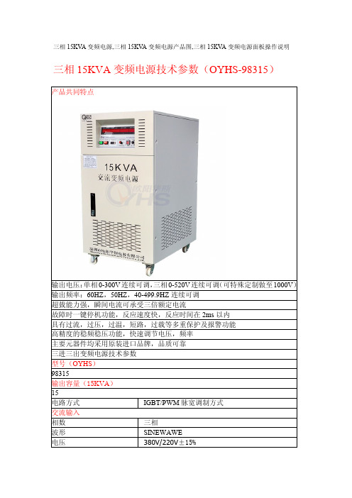
三相15KVA变频电源,三相15KVA变频电源产品图,三相15KVA变频电源面板操作说明
超臷能力强,瞬间电流可承受三倍额定电流
故障时一键停机功能,反应速度快,反应时间在 2ms 以内
具有过流,过压,过温,短路,过载等多重保护及报警功能
高精度的稳频稳压功能,快速调节电压,频率
主要元器件均采用原装进口品牌,品质可靠
三进三出变频电源技术参数
型号(OYHS)
98315
输出容量(15KVA)
15
需先按 OFF/RESET 键后进行。
5.按启动开关:按此开关前请先关闭输出开关。
6.调整输出电压:将输出电压切换开关切至所需档位。
(a)Lo-V 档位 0-150V
PS:150V 以下请用此档。
(b)Hi-V 档位 0-300V
PS:150V 以上请用此档。
7.将负载输入线接上,打开输出开关即可顺得获得各功能显示器上所
续可调
频率
60HZ,50HZ,40-499.9HZ 连续可调
频率稳定率
≤0.01%
低档最大电流(A)
42A(0-260V)
高档最大电流(A)
21A(0-520V)
整机性能
电源稳压率
﹤1%
负载稳压率
﹤1%
波形失真度
﹤1%
效率
﹥90%
反应时间
≤2ms
波峰因子
3:1
保护装置
具有过压,过流,超载,输入欠压,过高温,短路
重量(KG) 260
尺寸(H*D*W)mm 850*650*500
注:1 以上尺寸不含脚输高度
2 可根据顾客要求规格特别定制
3 本公司产品规格不断研发改进,规格若有变更,恕不另行通知
三相 15KVA 变频电源说明书
■注意事项
感谢您购买本公司产品,在使用前请务心详阅此手册,并请妥善保存。
平均重量控制器使用说明

YJ15平均重量控制器说明书中国核动力研究设计院三所二○○三年八月YJ15平均重量控制器1.简介平均重量控制器是根据烟支重量核扫描器输出信号变化来控制平准器电机正反转,使平准器上下移动,从而达到控制烟支重量的目的。
控制器可对烟支信号自动调整,无需人为干预。
该控制器包括PLC、信号调理盒。
PLC从系统工控机接收系统参数和要求,向系统工控机传递测量数据和工作状态。
由系统工控机显示当前烟支重量和重量偏移,以及运行状态,用户可以方便地通过简单的键盘操作更改目标重量、重量调整范围、重量报警范围、微调重量测量系数,也可调节平准器电机单次运行调整时间,开启或关闭重量控制,检查核扫描器状态等。
2.控制器组成YJ15平均重量控制器包括PLC、信号调理盒,需外部电源110VAC/1A和24VDC/0.5A。
PLC接收烟支重量核扫描器输出的电压信号,计算烟支重量,控制平准器电机正反转以调节烟支重量,从系统工控机接收系统参数和要求,向系统工控机传递测量数据和工作状态。
信号调理盒控制烟支重量核扫描器的温度,为烟支重量核扫描器提供±15V,调理PLC输出信号和烟支重量核扫描器输出的电压信号。
控制器工作流程如图一。
图一YJ15平均重量控制器流程图重量核扫描器输出的烟支重量电压信号经信号调理盒处理后送PLC,PLC根据电压值计算出烟支重量和重量偏差率,烟支重量超过一定范围时,PLC输出平准器电机运动信号,伺服电机控制器控制电机运动,使烟支重量满足要求。
2.1 信号调理盒信号调理盒控制烟支重量核扫描器的温度,为控制器和烟支重量核扫描器提供±15V,调理PLC输出信号和烟支重量核扫描器输出的电压信号。
接线图如图二。
图二:信号调理盒接线图2.2 PLCPLC接收烟支重量核扫描器输出的电压信号,计算烟支重量,控制平准器电机正反转以调节烟支重量,PLC从系统工控机接收系统参数和要求,向系统工控机传递测量数据和工作状态。
美国蜜糖电子微开关V15系列产品说明书

V15T16-EZ100A03V15T16-EZ100A03V15T16-EZ100A05V15T16-EZ100-K V15H16-CZ200V15H16-CZ300A0V15H16-CZ300A0V15H22-CZ100A0V15T16-CZ100V15T16-EZ100A02MICRO SWITCH Standard Basic SwitchesV15 SeriesDESCRIPTIONHoneywell’s MICRO SWITCH V-Basic Standard Switch, V15 Series is an electromechanical switch designed to provide outstanding value in a reliable global package. This switch is often ideal for “low-cost-of-failure” applications, where the cost is minimal to replace or service any failure related to the switch. With a wide variety of operating forces, andamperage ratings, the V15 is designed for numerous types of applications.Available in both pin plunger and levered styles, the V15 Series also offers a multitude of termination styles to fit almost any application.VALUE TO CUSTOMERS• Wide choice of electrical ratings: 0.1 A, 5 A, 10 A, 16 A, 22 A, 26 A• Certified for global use: UL/cUL, ENEC, CQC• Available with pin plungers or integral levers to meet multiple application and equipment requirements DIFFERENTIATION• Choice of actuation, termination, and operatingcharacteristics that can allow for flexibility in numerous types of applications• With a broad current capacity, one switch package can control a wide range of electrical loadsFEATURES• Broad range of electrical loads: 0.1 A, 5 A, 10 A, 16 A, 22 A, 26 A• Long service life: over one million mechanical operations • Gold contacts are also available for controlling logic level/low energy circuits• World-wide package size acceptance• UL/CSA, cUL, ENEC, and CQC approvals• Variants with cadmium-free contacts available POTENTIAL APPLICATIONS • Appliances • Furnaces• Gaming machines • Ice makers • Power washers • Vending machinesPORTFOLIOHoneywell offers a broad range of MICRO SWITCH basic switches including large, V-Basic, miniature, watertight, and special application switches.Sensing and Internet of Things004945Issue 10MICRO SWITCH Standard Basic Switches, V15 Seriesmax. inductive value (Amps)• GPA = General Purpose Amps (Inductive Load,75 % to 80 % power factor)• VL = Lamp Load2 Sensing and Internet of Things 3MICRO SWITCH Standard Basic Switches, V15 SeriesV15S05 PRODUCT NOMENCLATUREV15Switch TypeTemperatureGradeSLeverPositionElectrical Rating05V15 Series Standard Basic SwitchTerminal TypeCircuit Code—ZAOperating Force(at pin plunger max)200Mounting HolesKALever Type06Special DesignatorC—Housing Type1V15T10 PRODUCT NOMENCLATUREV15Switch TypeTemperatureGradeTLever PositionElectrical Rating10V15 Series Standard Basic SwitchTerminal TypeCircuit Code—ZAOperating Force(at pin plunger max)200Mounting HolesKALever Type06A special designator letter is used only when there is a special modificationto the switch.Review Product Specification to determine the exact differences. Below is an example.Special DesignatorC—Housing Type1V15H16/T16/T22/H22/T26 PRODUCT NOMENCLATUREV15Switch TypeTemperatureGradeHLever PositionElectrical Rating16V15 Series Standard Basic SwitchTerminal TypeCircuit Code—ZAOperating Force(at pin plunger max)200Mounting HolesKALever Type06Special DesignatorC—Housing Type1MICRO SWITCH Standard Basic Switches, V15 SeriesPinPlunger4 MICRO SWITCH Standard Basic Switches, V15 SeriesShortStraightLeverStandardStraightLeverSensing and Internet of Things 5MICRO SWITCH Standard Basic Switches, V15 SeriesLongStraightLeverSimulatedRoller6 MICRO SWITCH Standard Basic Switches, V15 SeriesShortRollerLeverSensing and Internet of Things 7MICRO SWITCH Standard Basic Switches, V15 SeriesRollerLever8 Sensing and Internet of Things 9MICRO SWITCH Standard Basic Switches, V15 SeriesMOUNTING DIMENSIONSFigure 1. V15 Series Standard Switch DimensionsFigure 2. V15 Series Metric Mounting Hole Dimensions for Ø 3 mm pins or screwsMetric mounting for Ø 3 mm pins or screws Ø 3,10 mm +0,10 mm/-0,05 mm 10,3 m m ±0,1 m m Ø 0.12 in +0.004 in/-0.002 in mounting holeFigure 3. V15 Series USA Mounting Hole Dimensions for #4 screws US mounting for #4 screws - K DesignatorØ 2,90 mm +0,10 mm/-0,05 mm10,3 m m ±0,1 m m Ø 0.11 in +0.004 in/-0.002 in mounting holeFigure 4. V15 Series Housing Dimensions10 Sensing and Internet of Things 1112 STANDARD LEVER OPTIONS • DIMENSIONSFigure 19. V15 Series A01/Straight Short LeverFigure 20. V15 Series A02/Standard Straight LeverFigure 21. V15 Series A03/Long Straight LeverFigure 22. V15 Series A04/Simulated Roller LeverFigure 23. V15 Series A05/Short Roller LeverFigure 24. V15 Series A06/Roller LeverNOTE: These dimensions apply for the “A” lever position. For the “B” leverposition, please add 5,7 mm [0.224 in].Position APosition BWarranty/RemedyHoneywell warrants goods of its manufacture as being free of defective materials and faulty workmanship during the appli-cable warranty period. Honeywell’s standard product warranty applies unless agreed to otherwise by Honeywell in writing; please refer to your order acknowledgment or consult your local sales office for specific warranty details. If warrantedgoods are returned to Honeywell during the period of coverage, Honeywell will repair or replace, at its option, without charge those items that Honeywell, in its sole discretion, finds defec-tive. The foregoing is buyer’s sole remedy and is in lieu of all other warranties, expressed or implied, including those of merchantability and fitness for a particular purpose. In no event shall Honeywell be liable for consequential, special, or indirect damages.While Honeywell may provide application assistance personally, through our literature and the Honeywell web site, it is buyer’s sole responsibility to determine the suitability of the product in the application.Specifications may change without notice. The information we supply is believed to be accurate and reliable as of this writing. However, Honeywell assumes no responsibility for its use.004945-10-EN | 10 | 12/19© 2019 Honeywell International Inc. All rights reserved.m WARNINGPERSONAL INJURYDO NOT USE these products as safety or emergency stop devices or in any other application where failure of the product could result in personal injury.Failure to comply with these instructions could result in death or serious injury.m WARNINGMISUSE OF DOCUMENTATION• The information presented in this product sheet is for reference only. Do not use this document as a product installation guide.•Complete installation, operation, and maintenanceinformation is provided in the instructions supplied with each product.Failure to comply with these instructions could result in death or serious injury.Honeywell Sensing and Productivity Solutions 9680 Old Bailes Road Fort Mill, SC 29707 ADDITIONAL MATERIALSThe following associated literature is available on the Honeywell web site at :• Installation instructions• Product part listing/nomenclature tree • Product application-specific information– Application note: Electronic sensors and eectromechanicalswitches in valves and flow meters – Application note: Electronic sensors and MICRO SWITCHswitches in industrial air compressors – Application note: Sensors and switches for potentialHVAC/R applications – Application note: Sensors and switches for valve monitorsand valve indicators – Application note: Sensors and switches in sanitary valves – Case study: Switching it up– Technical bulletin: Applying precision switchesFor more informationHoneywell Sensing and Internet of Things services its customers through a worldwide network of sales offices and distributors. For application assistance, current specifications, pricing or the nearest Authorized Distributor, visit or call:Asia Pacific +65 6355-2828Europe +44 (0) 1698 481481USA/Canada+1-800-537-69452-K6-K2V15T16-EZ100A06V15T16-EZ300A24V15T22-CP300V15T26-C1P300V15T16-EZ100A03V15T16-EZ100A03V15T16-EZ100A05V15T16-EZ100-K V15H16-CZ200V15H16-CZ300A0V15H16-CZ300A0V15H22-CZ100A0V15T16-CZ100V15T16-EZ100A02。
美国 英特利OPX-150 OTDR说明书l

OPX OTDR系列操作手册OPX2011目录1.技术规范 (3)通用技术指标 (5)2.OPX OTDR系列介绍 (5)主要特性 (5)功能模块描述 (5)包装清单 (6)仪表外观 (7)3.熟悉仪表 (8)仪表开关机说明 (8)功能菜单说明 (8)按键说明 (9)更改仪表通用参数 (11)设置按键属性 (11)设置显示属性 (11)设置日期和时间 (12)语言选择 (12)4.准备开始测试 (13)设置测量参数 (13)高级参数设置 (15)自动保存 (16)开始测量 (16)测试曲线 (17)打开曲线文件 (17)保存曲线文件 (17)其它曲线功能 (18)缩放/移动/标尺 (18)使用标尺功能 (18)使用缩放功能 (19)使用移动功能 (19)事件表 (20)事件点操作 (20)手动测试模式 (21)测量距离 (21)使用两点法测量衰减 (22)使用直线逼近法测量衰减 (22)使用五点法测量衰减 (22)测量反射 (23)测量回波反射 ORL (23)测试曲线操作 (24)选择曲线做比较 (24)自动曲线分析 (24)曲线过滤 (25)应用曲线模板 (25)查看曲线信息 (26)改变测量曲线的分析阈值 (26)5.与PC机通讯 (27)CD上的软件 (27)仪表与PC机的连接 (27)传送文件到PC (28)软件升级 (28)6.充电及存储 (29)仪表充电 (29)日常保存 (29)使用注意事项 (29)7.运输要求 (29)8.安全规程 (30)9.保修 (30)10.参数 (31)通用技术指标1.OPX OTDR系列介绍主要特性手持、小巧、功能全面专为室外使用而优化设计不同配置适用于不同的网络需求, (long-haul, metro/access)支持自动测试功能功能模块描述OPX-150 OTDR系列在选配下面相应的模块后,可执行光纤,光纤设备及光纤网络的特性指标。
OTDR模块;光源 (可选);光功率计 (可选);PON过滤器(可选;包装清单OPX-150 OTDR系列设备AC/DC 电源适配器USB接口线(Type A – mini Type B) 充电电池(安装于设备内)3米长的光纤跳线软件及操作手册CD仪表包仪表外观OTDR 测试口与光源口(选件)使用同一接口LED 指示灯▪“LASER” 灯亮时指示接口内的激光发射器正在工作。
产品说明书——精选推荐

产品说明书(用于2.4GHz版本)Cupid V3遥控电动直升机主要参数:主旋翼直径: 530m机身长度 500mm重量: 255g电池:7.4V 800mAh 锂聚合物电池遥控系统:4通道控制频率:2.4GHz安全警告请在使用本产品前仔细阅读本说明书!请妥善保管好此说明书,以便在需要时查阅。
警告:模型产品在使用时存在潜在的危险,使用时请注意安全!本产品不是玩具,它要求使用者有能力对其进行正确设定、调整。
当您使用本产品时,您有责任确保不会对自己及他人的人身及财产造成任何伤害。
十四岁以下儿童请勿使用该产品!请注意避免三岁以下儿童接触到本产品,以免造成危险!本产品只适合在室内或在无风的室外使用。
请不要在大风、下雨时或在黑夜使用本产品。
大风或雨淋有可能造成飞行时失控,造成摔机或者撞到人或建筑物等。
在使用前请务必对遥控设备进行检查。
发射机及接收机的任何故障都有可能造成飞机的失控或摔机。
在启动直升机之前,先检查舵机的动作是否正确,如果伺服器没有反应或者动作不正确,请不要使用。
请注意只有在适当的飞行场所进行飞行,确保飞机远离人群、建筑物、高压线、空中飞行器以及其它物品,否则会造成人员及财产的伤害或损害。
在进行飞行前检查时,注意把遥控器仰放在地面上,以防止遥控器意外倒下时触及油门造成飞机突然转动。
应避免塑料部件沾上油或酒精,因为一些部件沾上油后会发生溶解。
应避免电子部件受潮,否则会造成电子部件损坏。
在打开发射机之前,应把油门控制杆放到最小油门的位置;关闭发射机之前也应先关油门再关上发射机电源。
否则,有可能出现飞机突然高速转动而造成意外伤害。
切不可在开启油门后对发射机进行调整,否则有可能引起直升机突然加速而造成意外伤害。
请在飞行前确保发射机及接收机的电量足以完成飞行,以免在飞行过程中出现发射机或接收机断电而摔机。
仅可使用本机所附的充电器对发射机的电池或直升机电池进行充电。
如果使用其它充电器进行充电,必须确保不要对电池过充电,否则会造成电池过热、着火、爆炸或者其它意外发生。
外国(地区)企业常驻代表机构数据规范

下列文件中的条款通过本标准的引用而成为本标准的条款。凡是注日期的引用文件,其
随后所有的修改单(不包括勘误的内容)或修订版均不适用于本标准。然而,鼓励根据本标
准达成协议的各方研究是否可使用这些文件的最新版本。凡是不注日期的引用文件,其最新
版本适用于本标准。 rCYbSWRLIA
GB/T 19488.1 电子政务数据元 第 1部分:设计与管理规范
其中: a) 外国(地区)企业常驻代表机构年检信息包括:年检基本信息、年检核对信息、常驻 代表机构活动开展信息; yhUQsDgRT1 b) 业务申办信息包括:业务申办信息、申请信息、受理信息、核准信息、驳回信息、不 予受理信息、提交文件信息、归档信息。 MdUZYnKS8I
图 1 外国(地区)企业常驻代表机构业务框架图
外国 ( 地区 ) 企业常驻代表机构
企业(机构) 基本信息
◆主体身份代码 ◆企业 ( 机构 ) 名称 ◆注册号 ◆企业 ( 机构 ) 类型 ◆行业门类 ◆行业代码 ◆国别 ( 地区 ) ◆成立日期 ◆登记机关 ◆外资产业代码 ◆中西部优势产业 代码 ◆经营 ( 业务 ) 范围 ◆经营 ( 驻在 ) 期限 自 ◆经营 ( 驻在 ) 期限 至 ◆属地监管工商所 ◆邮政编码 ◆联系电话 ◆电子邮箱
发照信息 ◆发照原因 ◆发照人员 ◆发照日期 ◆领照人员 ◆联系电话 ◆补照原因
收照信息 ◆收照原因 ◆收照人员 ◆收照日期
文档
申请信息 ◆申请方式 ◆联系人 ◆证件类型 ◆证件号码 ◆联系电话 ◆移动电话 ◆申请日期
受理信息 ◆通知书文号 ◆受理意见 ◆受理人员 ◆受理日期
4.1.9 迁出信息 6y6v3ALoS89
4.1.10 注销信息 7M2ub6vSTnP
853控制柜调试指导书
为099-100。
6.6.5. 再将载重量增加至额定载荷就可达到超载报警。
称重装置的插头端子对照表见下面表格。
6.7、舒适感调整一般情况下调整3319中的加速度、减速度及其jerk0-jerk3进行调整。
根据现场的实际情况而定,一般不调。
6.8、试外招和消防a用万用表量H4插键是否有短路,正常后插好,拨好地址码。
外召地址从21开始,一个地址一层,以此类推,按下按钮能呼到指定楼层,完毕。
b按下消防开关,电梯能返回指定楼层,且轿厢显示紧急退出,轿门一直打开,则正常。
以上结束后电梯上下反复运行几次,正常则调试完毕。
七、故障排除3.9编码器定位出厂时主机已经与控制柜进行配对试验,定位角度已经存在变频器中,如果发现主机运行异常或驱动器内参数与主机实际参数不符,则需要重新定位。
断电,将钢丝绳拨离曳引轮,短接SW-A1和BY-A1到AC110V,上电使接触器吸合,设置好驱动器参数和电机铭牌参数,将RUN SOURCE设成“0”,RUN ENABLE设成“0”。
用服务器插入SVT2,并按“M-3-3-2”并按“ENTER”键进行确认主机定位,注意:定位过程中主机将旋转(在此过程中要确认抱闸已经打开);等待服务器出现“Learning finished”表示定位完成;注意:如果电机相位更换,则需要进行重新定位,或更改成原来相位;3.10点动运行时,BY、SW不能正常吸合检查安全信号输入、输出(IO)信号是否正常,如不正常应根据原理图检查线路;如信号正常,请检查驱动器参数,参见驱动器参数表。
3.11点动运行时,接触器、抱闸继电器及抱闸正常打开,电机不转,电流很大“Drive Overload”。
可能是变频器到主机三相相序不对,应按照正确方法连接主机动力线,参见“2.6 动力线检查”。
3.12自学习运行到顶层后,电梯不能正常运行检查run enable值,应该设置成“1”,另外请检查井道信号是否正常。
3.13常见驱动器故障3.13.1驱动器“Over current”信息电流过大。
各类电机型号及IP等级介绍
电机型号里的Y、YS、YSF、YT、YD、YL、YC分别是什么意思?Y系列全程为全封闭自扇冷式三相鼠笼型异步电动机。
使用非常普遍YS系列三相异步电动机功率较小,适用于小型机床、泵、压缩机的驱动,接线盒均在电动机顶部。
YSF、YT系列区别不大,都是风机专用三相异步电动机,是根据风机行业的配套要求,电动机在结构上采取了一系列的降噪、减振措施。
该系列电机具有高效节能、噪声低,启动性能好,运行可靠,使用安装方便等特点。
适用于风机安装和使用,是风机的理想配套产品。
YD为多速三相异步电动机,一般有4/2极8/6极8/4/2极6/4极12/6极8/6/4极8/4极6/4/2极12/8/6/4极适用范围:YD系列变极多速三相异步电动机是Y系列(1P44)三相异步电动机主要派生系列之一。
该系列电动机由于具有可随负载性质的要求而有级地变化转速,从而达到功率的合理匹配和简化变速系统的特点,是机械系统节约能耗的理想动力之一。
在机床、矿山、冶金、纺织、印染、化工、农机等工农业部门得到广泛的应用。
YD系列变极多速三相异步电动机对于国内同类型其他系列电动机具有效率高、堵转转矩大、噪声低、振动小、运行安全可靠等特点。
电动机符合“YD系列(1P44)变极多速三相异步电动机技术条件JB/T7127-93"的规定。
YD系列变极多速三相异步电动机采用B级绝缘,额定电压为380V,额定频率为50Hz,外壳防护等级为IP44,冷却方式为IC411,连续工作(S1)。
电动机运行地点海拔不超过1000m;环境空气温度随季节而变化,但不超过40℃;最低环境空气温度为-15℃;最湿月月平均最高相对湿度为90%,同时该月月平均最低温度不高于25℃。
YD系列电动机的功率等级及功率等级与安装尺寸的对应关系与国外同类型先进产品相当。
因而与国外同类型先进产品之间具有良好的互换性。
便于单机或与机床配套出口,也可以作为引进设备中同类型电动机的备用电动机YZD系列冶金起重用双速三相异步电动机适用范围:YZD系列电动机专门为各种冶金、起重要求变极调速机械开发制造的新型变极调速笼型电动机。
35V 150mA超低功耗 PC58LXXX_三端稳压稳器 Rev1.6

35V,150mA⏹介绍⏹特征•三端调节器•供电电压:4.5V 〜35V•输出范围:2.5V,3.3V,4.0V,5.0V,5.6V,12V •输出电流高达150mA •输出精度:<±2%•静态电流6μA@VIN =VO+2V (Typ )•内部热过载保护•内部短路限制•推荐电容:1uF~10uF⏹应用领域•智能电表•开关电源⏹订单信息零件号包装类型数量标记*SOT89-31000/盘SOT89-31000/盘DFN2x2-64000/盘SOT23-53000/盘SOT23-53000/盘TO923000/盘零件号输出电压PC58L025Vout=2.5V PC58L033Vout=3.3V PC58L040Vout=4.0V PC58L050Vout=5.0V PC58L056Vout=5.6V PC58L120Vout=12VPC58LXXX 提供过热,过流保护,以确保设备在良好的条件下工作。
PC58LXXX线性稳压器PC58LXXX 系列是高精度,高输入电压,低静态电流,高速,低压差线性稳压器,具有高纹波抑制能力。
该器件采用BCD 工艺制造。
PC58LXXX OGR PC58LXXX AOGR PC58LXXX DSR PC58LXXX TCR PC58LXXX ATCR PC58LXXX WGR *注:YY /Y =年;WW /W =周;PC58LXXX =产品名称;XXX =电压PC58LXXXOGRPC58LXXXATCRPC58LXXXAOGRPC58LXXXTCRPC58LXXXWGR⏹典型应用PC58LXXX⏹引脚说明PC58LXXX OGR系列序号名称功能1OUT输出2GND地3IN输入PC58LXXX AOGR系列序号名称功能1GND地2IN输入3OUT输出PC58LXXX DSR系列序号名称功能1NC2NC3IN输入4OUT输出5GND地6NCPC58LXXX TCR系列PC58LXXX ATCR系列PC58LXXX WGR系列绝对最大额定值注意(1):PCB底层有6cm2地平面散热铜箔。
斐讯路由产品销售手册--完整版
PHICOMM 斐讯路由产品销售手册上海斐讯数据通信技术有限公司包装盒外观:举例:FIR302B1路由器产品包装盒正面写有300M无线路由器,这是说明该路由器是可以达到300M的传输速率。
“放飞梦想系列 FIR302B”是该产品的型号,F代表斐讯,I代表云,R路由器。
30X代表是300M,2代表2根天线。
B代表该设备用的是美国博通(Broadcom)生产的芯片。
如果是“M”就带表联发科技股份有限公司(MediaTek Inc)生产的芯片。
斐讯产品型号及产品描述:2 产品包装盒反面有“绿色节能云服务”智慧云服务:云注册,远程管控,软件升级提醒,支持斐讯云路由器安卓客户端斐讯云路由手机app客户端,扫描下方二维码即可下载。
(仅支持安卓手机)解释:云注册是在路由器设置界面的最后一步需要注册一个邮箱和密码,该邮箱和密码就成了用户的云账号和密码,手机下载APP客户端之后,便可以用手机登陆,只要能上网的地方,就可以远程管控,设置黑名单等,如果路由器版本升级,我们通过云服务器直接发到该邮箱里,用户便可以自己升级。
“绿色节能”超低功耗芯片,WIFI开关,绿色节能。
解释:因为用的是博通5357的芯片,所以功耗低,用电少,路由器界面里有WIFI控制开关,(该处指的开关不是后面的WPS键)。
“信号稳定智能调节”双5dBi智能天线,信号稳定,覆盖广;智能调节无线信号强度,减少辐射后顾之忧。
解释:天线为5dBi智能天线,信号比较稳定,覆盖面积广。
信号可以调节。
可以减少辐射。
“安全性能高,稳定兼容”支持WiFi访问保护(WPA/WPA2),轻松防蹭网,先进美国博康芯片方案,成熟稳定兼容好。
解释:随着科技的进步,很多的黑客,木马等病毒也在不断提高其攻击能力,很多路由器的后台留有很多后洞(中央电视新闻报道过几个品牌),病毒通过路由器进入用户电脑窃取用户信息,使用户的个人信息,银行账户及密码泄露。
很多人喜欢在淘宝上购物,殊不知在付款的时候就会被潜在的病毒记录下银行账号及密码。
- 1、下载文档前请自行甄别文档内容的完整性,平台不提供额外的编辑、内容补充、找答案等附加服务。
- 2、"仅部分预览"的文档,不可在线预览部分如存在完整性等问题,可反馈申请退款(可完整预览的文档不适用该条件!)。
- 3、如文档侵犯您的权益,请联系客服反馈,我们会尽快为您处理(人工客服工作时间:9:00-18:30)。
OPTEK TechnologyVertical Cavity Surface Emitting Laser in FC Optical Sub-AssemblyThe OPV31XF and OPV31XYF are a high performance 850nm Vertical Cavity Surface Emitting Laser (VCSEL) packaged for high speed communication links. OPV31XF combines all the performance advantages of a VCSEL with the addition of a power monitor diode for precise control of optical power. The VCSEL is a current device assuming the forward voltage drop, from 1.6 to 2.2 volts, is achieved.The OPV31XF and OPV31XYF are electrically and optically identical, they differ only in pin out. Refer to the charts below.The OPV315 devices have an attenuation coating on the interior surface of the lens. The coating reflects about 40% of the light reducing noise in special applications, preventing overdriving of sensitive detectors and doubling monitor current.These product’s include a combination of features including high speed with high output power and a concentric beam there by making it an ideal transmitter for integration into all types of data communications equipment.Applications include: • Fibre Channel • Gigabit Ethernet • ATM• VSR (Very Short Reach) • Intra-system links• Optical backplane interconnects .Product Photo HereOrdering InformationPlease order part number:OPV314F—Common VCSEL Cathode / Pin Diode Anode OPV314YF—Common VCSEL Anode / Pin Diode CathodeOPV315F—Common VCSEL Cathode / Pin Diode Anode, Attenuated PowerOPV315YF—Common VCSEL Anode / Pin Diode Cathode1, Attenuated PowerPin Connection 1 VCSEL Anode2 VCSEL Cathode/PD Anode 3PD CathodeOPV314F, OPV315F Pin Connection 1 VCSEL Cathode2 VCSEL Anode/PD Cathode 3PD AnodeOPV314YF, OPV315YF Additional laser safety information can be found on the Optek website. See application #221. Classification is not marked on the device due to space limitations. See package outline for centerline of optical radiance. Operating de-vices beyond maximum rating may cause de-vices to exceed rated classificationAbsolute Maximum Ratings (T A = 25o C unless otherwise noted)Storage Temperature -40° C to +100° C Lead Soldering Temperature (1/16” (1.6mm) from case for 5 seconds with soldering iron)260° C (1)Operating Temperature0° C to +70° C Maximum Reverse Voltage10 V Maximum Forward Peak Current 20 mA Electrical Characteristics (T A = 25°C unless otherwise noted)SYMBOLPARAMETER MIN TYP MAX UNITS TEST CONDITIONP T50 Total Coupled Power (OPV314, OPV314Y) 500 µW I F = 7 mA,Fiber 50/125µm (OPV315, OPV315Y) 250 µW I TH Threshold Current 0.8 3.0 mA Note1 V F Forward Voltage 1.6 2.2 V I F = 7 mA I R Reverse Current 35 nA V R = 5 V R SSeries Resistance20 55 ohms Note 2η Slope Efficiency (OPV314, OPV314Y) 50 µW/mANote 3 (OPV315, OPV315Y)25 µW/mA I RPD Reverse Current, photo diode30 nA V R = 40 VMonitor Current (OPV314, OPV314Y)50µΑ I F = 7 mA, V R = 5 V (OPV315, OPV315Y) 100 µΑ λ Wavelength 840 860 nm ∆λ Optical Bandwidth 0.85 nmt r Rise Time 90 ps 20% to 80% t fFall Time120ps80% to 20%N RI Relative Intensity Noise -123 db/Hz ∆η/∆ΤTemp Coefficient of Slope Efficiency-0.4 %/°C (0° - 70° C) ∆l TH /∆T Temp Coefficient of Threshold Current ±0.1 mA0° - 70° C∆λ/∆TTemp Coefficient of Wavelength0.06 nm/°C 0° - 70° C ∆Vf/∆T Temperature Coefficient for VF-2.5mV/°CI M NOTES:(1) Threshold Current is based on the two line intersection method specified in Telcordia GR-468-Core. Line 1 from 4 mA to 6 mA.Line 2 from 0 mA to 0.5 mA.(2) Series Resistance is the slope of the Voltage-Current line from 5 to 8 mA.(3) Slope efficiency, is the slope of the best fit LI line from 5 mA to 8 mA using no larger than .25 mA test interval points.Measured with a 50/125 µm fiber.(4) Linearity—Using data points taken for slope efficiency above, data L/delta I shall be calculated for each adjacent pair of points.Forward Voltage (V F) vs Forward Current (I F) vs TemperturePower Out (PO) vs Forward Current (I F ) vs Temperature0%20%40%60%80%100%120%140%0.000.501.001.502.002.503.003.504.004.505.005.506.006.507.007.508.008.509.00I F (mA)P O (µW )Threshold vs Temperature1.01.11.21.31.41.51.61.71.81.92.0010203040506070Temperature (°C)T y p i c a l T h r e s h o l d C u r r e n t (m A )Pin Connection1 VCSEL Anode2 VCSEL Cathode/PD Anode 3PD CathodeOPV314F, OPV315F 1 2 3VCSEL PD1 2 3VCSEL PDDIMENSIONS ARE IN [MILIMITERS] AND INCHES.Pin Connection 1 VCSEL Cathode2 VCSEL Anode/PD Cathode 3PD AnodeOPV314YF, OPV315YF。
