AUNA-202中文资料
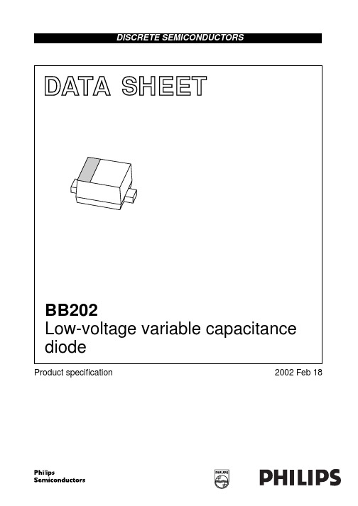
BB202中文资料
2002 Feb 18
3
Philips Semiconductors
Product specification
Low-voltage variable capacitance diode
PACKAGE OUTLINE Plastic surface mounted package; 2 leads
BB202
BB202
This data sheet contains data from the objective specification for product development. Philips Semiconductors reserves the right to change the specification in any manner without notice. This data sheet contains data from the preliminary specification. Supplementary data will be published at a later date. Philips Semiconductors reserves the right to change the specification without notice, in order to improve the design and supply the best possible product. This data sheet contains data from the product specification. Philips Semiconductors reserves the right to make changes at any time in order to improve the design, manufacturing and supply. Changes will be communicated according to the Customer Product/Process Change Notification (CPCN) procedure SNW-SQ-650A.
Behringer U-CONTROL UCA202 Ultra-Low Latency 2 In

User ManualU-CONTROL UCA202Ultra-Low Latency 2 In/2 Out USB/WAudio Interface with Digital Output V 6.0Table of ContentsThank you (2)Important Safety Instructions (3)Legal Disclaimer (4)Limited Warranty (4)1. Introduction (6)2. System Requirements (7)3. Operating Elementsand Connections (8)4. Working with the UCA202 (9)5. Audio Connections (10)6. Specifications (11)Thank youThank you for choosing the new UFO202 U-PHONO interfacefrom Behringer. You will now be able to transfer all your greatalbums from the vinyl and tape eras into the digital realm withthe help of this easy-to-use device. It features stereo RCA inputsand outputs to allow both monitoring and recording of the audiosource. The USB connection will work with either PCs or Maccomputers, so no drivers are needed for installation, and poweris supplied through the USB cable. The separate headphonesoutput allows you to play back your recordings at any time,even if you don’t have any loudspeakers available. We’ve alsoincluded free software to help you transfer and edit the music ina streamlined fashion, allowing you to spend less time fidgetingwith settings and more time listening to your favorite songs.Terminals marked with this symbol carry electrical current of sufficientmagnitude to constitute risk of electric shock. Use only high-quality professional speaker cables with ¼" TS or twist-locking plugs pre-installed. All other installation or modification should be performed only by qualified personnel.This symbol, wherever it appears, alerts you to the presence of uninsulateddangerous voltage inside the enclosure - voltage that may be sufficient to constitute a risk of shock.This symbol, wherever it appears, alerts you to important operating andmaintenance instructions in the accompanying literature. Please read the manual.CautionTo reduce the risk of electric shock, do not remove thetop cover (or the rear section). No user serviceable parts inside. Refer servicing to qualified personnel.CautionTo reduce the risk of fire or electric shock, do not exposethis appliance to rain and moisture. The apparatus shall not be exposed to dripping or splashing liquids and no objects filled with liquids, such as vases, shall be placed on the apparatus.CautionThese service instructions are for use by qualifiedservice personnel only. To reduce the risk of electric shock do not perform any servicing other than that contained in the operation instructions. Repairs have to be performed by qualified service personnel.1. Read these instructions.2. Keep these instructions.3. Heed all warnings.4. Follow all instructions.5. Do not use this apparatus near water.6. Clean only with dry cloth.7. Do not block any ventilation openings. Install in accordance with the manufacturer’s instructions.8. Do not install near any heat sources such as radiators, heat registers, stoves, or other apparatus (including amplifiers) that produce heat.9. Do not defeat the safety purpose of the polarized or grounding-type plug. A polarized plug has two blades with one wider than the other. A grounding-type plug has two blades and a third grounding prong. The wide blade or the third prong are provided for your safety. If the provided plug does not fit into your outlet, consult an electrician for replacement of the obsolete outlet.10. Protect the power cord from being walked on or pinched particularly at plugs, convenience receptacles, and the point where they exit from the apparatus.11. Use only attachments/accessories specified by the manufacturer.12. Use only with the cart, stand, tripod, bracket, or table specified by the manufacturer, or soldwith the apparatus.4U-CONTROL UCA202 User ManualWhen a cart is used, use caution whenmoving the cart/apparatus combination to avoid injury from tip-over.13. Unplug this apparatus duringlightning storms or when unused for longperiods of time. 14. Refer all servicing to qualified service personnel. Servicing is required when the apparatus has been damaged in any way, such as power supply cord or plug is damaged, liquid has been spilled orobjects have fallen into the apparatus,the apparatus has been exposed to rain ormoisture, does not operate normally, or hasshall remain readily operable.17. Correct disposal of this product: This symbol indicates that this product must not be disposed ofwith household waste,according to the WEEE Directive (2012/19/EU) and your national law. This product should be taken to a collection center licensed for the recycling of waste electrical and electronic equipment (EEE). The mishandling of this type of waste could have a possible negative impact on the environment and human health due to potentially hazardous substances that are generally associated with EEE. At the same time, your cooperation in the correct disposal ofthis product will contribute to the efficient use of natural resources. For more information about where you can take your waste equipment forrecycling, please contact your local city office, or your household waste collection service.18. Do not install in a confined space, such as a book case or similar unit.19. Do not place naked flame sources,such as lighted candles, on the apparatus.20. Please keep the environmental aspects of battery disposal in mind. Batteries must be disposed-of at a battery collection e this apparatus in tropical and/or moderate climates.yient towherever it s you to rating and n the ease read isk of do not rear parts inside. ersonnel.isk ofshock, do o rain and all notplashingwithbe placednstructionsqualified educe notr than thatbattery collection point.21. This apparatus may be used in tropical and moderate climates up to 45°C.1. IntroductionWelcome to the family of U-CONTROL users and thank you for expressing your confidence in Behringer products by purchasing the UCA202. With the UCA202 you have purchased a high-performance audio interface that includes a USBconnector. It is thus an ideal sound card for your laptop computer or an essential recording/playback component for studio environments that involve desktop computers.The UCA202 is PC and Mac-compatible. Therefore, no separate installation procedure is required, while the operating system drivers ensure an extremely short latency. Thanks to its robust construction and compact dimensions, the UCA202 is also ideal for traveling. The separate headphones output allows you to play back your recordings at any time, even if you don’t happen to have any loudspeakers available.2 inputs and outputs as well as the digital stereo output give you total connecting flexibility to mixing consoles, loudspeakers or headphones. Power is supplied to the unit via the USB interface. The LED gives you a quick check that the UCA202 is properly connected to the computer. The UCA202 is the ideal extra for every computer musician.1.1 Before you started1.1.1 ShipmentYour UCA202 was carefully packed at the assembly plant to assure secure transport. Should the condition of the cardboard box suggest that damage may have taken place, please inspect the unit immediately and look for physical indications of damage.◊ Damaged equipment should NEVER be sent directlyto us. Please inform the dealer from whom you acquired the unit immediately as well as the transportation company from which you tookdelivery. Otherwise, all claims for replacement/repair may be rendered invalid.◊ Please always use the original packaging to avoiddamage due to storage or shipping.◊ Never let unsupervised children play with theequipment or with its packaging.◊ Please dispose of all packaging materials in anenvironmentally friendly fashion.1.1.2 Initial operationPlease make sure the unit is provided with sui cient ventilation, and never place the UCA202 on top of an amplii er or in the vicinity of a heater to avoid the risk of overheating.The current supply is made via the USB connecting cable,so that there is no external power supply unit required.All required safety precautions have been adhered to.1.1.3 Online registrationPlease register your new Behringer equipment right after yourpurchase by visiting and read the termsand conditions of our warranty carefully.Should your Behringer product malfunction, it is our intentionto have it repaired as quickly as possible. To arrange forwarranty service, please contact the Behringer retailer fromwhom the equipment was purchased. Should your Behringerdealer not be located in your vicinity, you may directly contactone of our subsidiaries. Corresponding contact information isincluded in the original equipment packaging (Global ContactInformation/European Contact Information). Should yourcountry not be listed, please contact the distributor nearestyou. A list of distributors can be found in the support area ofour website ().Registering your purchase and equipment with us helps usprocess your repair claims more quickly and efficiently.Thank you for your cooperation!2. System Requirements◊ The UCA202 is PC and Mac-compatible. Therefore,no installation procedure or drivers are requiredfor the correct functioning of the UCA202.To work with the UCA202, your computer must fulfillthe following minimum requirements:2.1 Hardware connectionUse the USB connecting cable supplied with the UCA202to connect the unit to your computer. The USB connection alsosupplies the UCA202 with current. You can connect a varietyof devices and equipment to the inputs and outputs.3. Operating Elements and Connections3.1 Front panelFig. 3.1: Front panel UCA202(1) The LED indicates the status of the USB power supply.(2) DIGITAL OUTPUT : The Toslink jack carries an S/PDIF signalwhich can be connected via a i ber optic cable, for example, to the digital input of an effects device.(3)Use the jack to connect a standard pair of headphonesequipped with a 1/8" TRS connector.(4) The VOLUME control adjusts the volume level of theheadphones output. Turn the control fully to the left before you connect the headphones. This helps you avoid the damage that is caused by high volume settings.3.2 Rear panelFig. 3.2: Back of the UCA202(5) Use the jack to connect a standard pair of headphonesequipped with a 1/8" TRS connector. (6) Use the LINE-OUT jacks for audio cables with RCA connectors.(7) Use the LINE-IN jacks for audio cables with RCA connectors.(8) The OFF/ON-MONITOR switch activates the monitorfunction. In this case the input signal is routed directly to the headphones output.4. Working with the UCA2024.1 Application example ArrayFig. 4.1: Common version with the UCA202To provide a professional recording interface between mixing console and computer, you can use the UCA202 in combination with a suitable mixing console that includes subgroup outputs. This type of setup allows you to record several signals in the computer at the same time, to simultaneously play back several takes or playbacks which have been recorded, and to listen to the whole recording via loudspeakers (or headphones). Figure 4.1 shows a possible setup with one UCA202.Connect the outputs of the subgroup (in this case ALT 3-4 OUT)with the inputs of the UCA202 (6). You can choose to connect the outputs (5) of the interface either to the TAPE INPUT sockets or to your monitor speakers. You can connect control headphones to the socket (3) of the UCA202 or to the headphones output of your mixing console. Use the USB cable supplied with the unit to connect your PC or MAC via the USB interface.By routing each channel that you want to record through the ALT3-4 subgroup, you can now use the input channels of the mixing console to record different signals (e.g. microphone, guitar, sound module, etc.) in the computer. If you connect the OUT jacks of the UCA202 to channel inputs 7/8 (not via TAPE INPUT), make sure that the signal is not switched to the subgroup but instead to the main output of your mixer (MUTE key on the UB1204FX-PRO in channel 7/8 not pressed). Otherwise feedback can occur. Make sure that you use the SOURCE section on the mixing console to select the correct monitoring paths (ALT 3-4 and MAIN MIX or ALT 3-4 and TAPE).If you lead the UCA202 back via a channel input (not TAPE INPUT), you can also use the aux path in the channel to set up a monitor mix for live musicians. To do this, use the Aux Send (e.g. Aux 1) in this channel input. If the musicians want to hear themselves as well as the playback or previous recording takes, use the Aux Sends in the recording channels to mix in the recording signals with the monitor mix.5. Audio ConnectionsAlthough there are various ways to integrate the UCA202 into your studio or live set-up, the audio connections to be made will basically be the same in all cases:5.1 WiringPlease use standard RCA cables to connect the UCA202to other audio equipment. You can also use an adapter cable.Fig. 5.1: RCA cableFig. 5.2: Adapter cable with ¼" jack5.2 Headphones connectionThe UCA202 is provided with a headphones jack. Here, you can connect any standard pair of stereo headphones with a 1/8" TRS connector. 6. SpecificationsConnectors RCA, unbalancedInput impedance approx. 27 kΩMax. input level 2 dBVLine OutConnectors RCA, unbalancedOutput impedance approx. 400 ΩMax. output level 2 dBVDigital OutputSocket Toslink, optical cableOutput format S/PDIFPhones OutSocket 1/8" TRS stereo jackOutput impedance approx. 50 ΩMax. output pegel -2 dBu, 2 x 3.7 mW @ 100 ΩConnectors type AConverter 16-bit converter Sample rate 32.0 kHz, 44.1 kHz, 48.0 kHz Frequency response 10 Hz to 20 kHz,±*********************10 Hz to 22 kHz,±********************* THD 0.05% typ. @ -10 dBV, 1kHz Crosstalk -77 dB @ 0 dBV, 1 kHz Signal-to-noise ratio A/D 89 dB typ. @1 kHz, A-weightedD/A 96 dB typ. @1 kHz, A-weightedUSB connection 5V , 100 mA max.Dimensions (H x W x D) approx. 0.87 x 2.36 x 3.46"approx. 22 x 60 x 88 mm Weight approx. 0.10 kgBehringer always takes great care to ensure the highest standard of quality. Any modifications which may be necessary will be made without prior notification. Specifications and appearance of the equipment can therefore differ from the details or illustrations shown.FEDERAL COMMUNICATIONSCOMMISSION COMPLIANCEINFORMATIONResponsible Party Name: Music Tribe Commercial NV Inc.Address:901 Grier DriveLas Vegas, NV 89118USAPhone Number: +1 747 237 5033U-CONTROL UCA202This equipment has been tested and found to comply with the limitsfor a Class B digital device, pursuant to part 15 of the FCC Rules.These limits are designed to provide reasonable protection againstharmful interference in a residential installation. This equipmentgenerates, uses and can radiate radio frequency energy and, if notinstalled and used in accordance with the instructions, may causeharmful interference to radio communications. However, there is noguarantee that interference will not occur in a particular installation.If this equipment does cause harmful interference to radio or televisionreception, which can be determined by turning the equipment offand on, the user is encouraged to try to correct the interference by oneor more of the following measures:• Reorient or relocate the receiving antenna.• Increase the separation between the equipment and receiver.• Connect the equipment into an outlet on a circuit different fromthat to which the receiver is connected.Consult the dealer or an experienced radio/TV technician for help.This device complies with Part 15 of the FCC rules. Operation is subjectto the following two conditions:(1) this device may not cause harmful interference, and(2) this device must accept any interference received, includinginterference that may cause undesired operation.Important information:Changes or modifications to the equipment not expressly approved byMusic Tribe can void the user’s authority to use the equipment.We Hear You。
AQV202中文资料
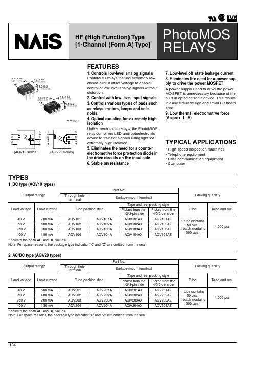
Turn off time*
Typical Maximum
Toff
characteristics I/O capacitance
Typical Ciso
Maximum
0.23 ms 0.07 ms
0.22 ms 0.13 ms 1 ms
0.07 ms 0.07 ms 1 ms 1.3 pF 3 pF
Item
Symbol AQV101(A) AQV102(A) AQV103(A) AQV104(A)
Remarks
LED forward current
IF
50 mA
LED reverse voltage
VR
Input
Peak forward current
I FP
6V
1A
f = 100 Hz, Duty factor = 0.1%
Non-condensing at low temperature
AQV104AZ
*Indicate the peak AC and DC values. Note: For space reasons, the package type indicator "X" and "Z" are omitted from the seal.
Packing quantity
0.18 A 0.5 A
100 ms (1 shot)
Power dissipation
P out
360 mW
Total power dissipation
PT
410 mW
I/O isolation voltage
V iso
1,500 V (AC)
adm202参数

adm202参数ADM202是一种常见的双路RS-232驱动器/接收器,用于将逻辑电平转换为RS-232电平。
它通常用于串行通信中,将数字信号转换为可以在电缆上传输的电压。
ADM202具有多种应用领域,例如计算机网络、工业自动化和通信设备等。
ADM202的工作原理非常简单。
它接收来自逻辑电路的输入信号,并将其转换为符合RS-232标准的电平。
这样,它可以将来自计算机或其他设备的数字信号转换为适合串行通信的电压。
ADM202还具有保护电路,可以保护输入和输出免受电压浪涌和静电放电的损害。
ADM202的设计使其非常适合在工业环境中使用。
它具有较高的电压转换能力和较强的抗干扰能力,能够在恶劣的工作条件下稳定运行。
此外,ADM202还具有低功耗和小尺寸的特点,使其易于集成到各种设备中。
ADM202不仅具有出色的性能,还具有广泛的兼容性。
它可以与各种RS-232设备配合使用,如计算机、打印机、调制解调器等。
ADM202还支持多种通信速率,从低速的300bps到高速的115.2kbps都可以实现可靠的数据传输。
除了常见的应用领域外,ADM202还在一些特殊的领域中得到了广泛的应用。
例如,在医疗设备中,ADM202可以用于将传感器数据传输到计算机,实时监测患者的生命体征。
在工业自动化中,ADM202可以用于控制系统之间的数据交换,实现智能化生产。
在通信设备中,ADM202可以用于将数字信号转换为模拟信号,实现语音通信。
ADM202作为一种双路RS-232驱动器/接收器,具有广泛的应用领域和出色的性能。
它的设计使其适用于各种工作环境,并且与其他设备兼容性强。
无论是在计算机网络、工业自动化还是通信设备中,ADM202都发挥着重要的作用,为数据传输提供可靠的解决方案。
无论是在医疗设备中监测患者的生命体征,还是在工业自动化中实现智能化生产,ADM202都是不可或缺的关键组件。
相信随着技术的不断发展,ADM202将继续在各个领域中发挥重要作用,推动着人类社会的进步与发展。
澳泰 AVI202 网络摄像机 说明书
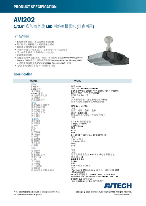
AVI202Copyright © 2008 Shenzhen Austech(BT) Limited. All Rights Reserved. * The specifications are subject to change without notice.** Dimensional Tolerance: ± 5mm Specification202I V AL E D OM 1/3.6" 彩色 红外线 LED 网络型摄影机 (日夜两用)影片传输不延迟,提供清晰流畅的影像数字格式 / 模拟格式 / 双影像输出模式具位移侦测与警报输出等功能外部声音输入 / 输出端子,方便使用于双向语音对话日 / 夜监看模式 (具隐藏式红外线功能)高画质撷取组件支持完整的 IP 监控系统,例如:中控管理系统 (Central Management System, CMS) 软件、网络储存设备 (Network- Attached Storage, NAS)、网络影像录像主机 (Network Video Recorder, NVR) 等等 选配) 手机远程监看及 3G 自动报警功能产品特色网络L AN 埠L AN 速度支持协议Frame 速度在线使用者人数安全机制网络管理软件影音影像传输压缩格式影像远程控制影像调整功能声音压缩格式声音输入声音输出摄影机感光组件画质像素分辨率镜头F-值可视角度快门速度红外线最低照度影像输出背光补偿白平衡其他远程控制位移侦测警报传输动作警报 I / O 电源工作温度工作湿度尺寸 (mm)使用环境网络浏览最低设备需求标准 RJ4510 / 100 Based-T Ethernet DDNS, PPPoE, DHCP, NTP, SNTP, TCP / IP,ICMP,SMTP, FTP, HTTP, RTP, RTSP NTSC:30, PAL:2510多人密码管理,并依密码可区分权限最多可同时控制16 支网络摄影机MPEG4 / MJPEG 支援亮度、对比、色相、色彩uLaw , 128kbps 隐藏式麦克风接收,外部收音端子支援1 / 3.6" 图像传感器738(H) x 480(V)480TV lines f3.6F2.080°1 / 60 (1 / 50) to 1 / 100,000 sec.支援1 Lux / F2.01.0 Vp-p. 75ΩAUTO ATW支援支援可设定影像上传到 FTP 和 / 或电子邮件地址警报输入 x112VDC, 0.5A 0~40?85%158 x 40.2 x 115.2室内-Pentium 4 CPU 1.3 GHz 或更高,或同等级 AMD -256 MB RAM -AGP 图形适配卡、Direct Draw 、32MB RAM -Windows XP 、Windows 2000 Server 、ME 、98、DirectX 9.0 或更新版本-Internet Explorer 6.x 或更新版本。
ALC202资料
ALC202 AC’97 Audio CODECDraft Spec.PreliminaryVersion 0.62September 26, 20011.Featuresl Single chip audio CODEC with high S/N ratio (>90 dB).l20-bit DAC, 18-bit ADC.l Stereo full-duplex CODEC with independent and variable sampling rate.l 4 analog line-level stereo input with 5-bit volume control : LINE_IN,CD,VIDEO,AUX l 2 analog line-level mono input : PC_BEEP,PHONE_IN.l Mono output with 5-bit volume control.l Stereo output with 6-bit volume control.l 2 MIC inputs: Software selectable.l Power management and enhanced power saving.l3D Stereo Enhancementl External Amplifier power down capability.l Multiple CODEC extension.l Compliant with AC’97 2.2 specificationl50mW/8W amplifier at LINE/ Headphone outputl Jack-detect function to mute LINE/MONO/HP output, to control S/PDIF output.l Supports S/PDIF out is compliant with AC’97 rev2.2.l 2 GPIO pins.l14.318MHzà24.576MHz digital PLL.l Supports double sampling rate (96KHz) of DVD audio playback.l+30dB boost preamplifier for MIC input.l Power support: Digital: 3.3V Analog: 3.3V/5Vl Standard 48-Pin LQFP Package2.Pin DescriptionXTLSEL=floating, the clock source is 24.576MHz crystal or external clock. (Default) XTLSEL=pull low, select 14.318MHzà24.576MHz digital PLLThe default state of MX7A.15 if power on latched inversely from XTLSEL.2.7 Mixer Block DiagramP C M o u tP C M o u t3.ALC202 Pin Assignment3.1 Pin-Out Diagram:MONO-OUTAVDD2TRUE-LINE-OUT-LAVSS2GPIO0ID0#XTLSEL EAPD(JD)234567SPDIFO/TESTMIC2VIDEO-R AUX-R PHONELINE-IN-R A V S S 1A F I L T 2N C D V D D 1ALC202AL I N E -O U T -R CD-R GPIO1L I N E -O U T -L N C V R D A V R A D A F I L T 1V R E F O U T V R E F A V D D 1LINE-IN-L MIC1CD-GND CD-L VIDEO-L AUX-L X T L -I N X T L -O U T D V S S 1S D A T A -O U T B I T -C L K D V S S 2S D A T A -I N D V D D 2S Y N C R E S E T #P C -B E E PNCTRUE-LINE-OUT-RMONO-OUTAVDD2HP-OUT-LAVSS2GPIO0ID0#XTLSEL EAPD(JD)234567SPDIFO/TESTMIC2VIDEO-R AUX-R PHONELINE-IN-R A V S S 1A F I L T 2N C D V D D 1L I N E -O U T -R CD-R HP-OUT-RGPIO1L I N E -O U T -L N C V R D A V R A D A F I L T 1V R E F O U T V R E F A V D D 1LINE-IN-L MIC1CD-GND CD-L VIDEO-L AUX-L X T L -I N X T L -O U T D V S S 1S D A T A -O U T B I T -C L K D V S S 2S D A T A -I N D V D D 2S Y N C R E S E T #P C -B E E PNC4.Mixer RegistersAll mixer register access with odd-number will return with 0.Reading unimplemented registers will return 0.should be ignored.3Fh 94.5 dB attenuation •When ID=01,10,11, the default value is 0000H.3Fh 94.5 dB attenuation •When ID=01,10,11, the default value is 0000H.1Fh 46.5 dB attenuation•Implement 5-bit volume control only. Writing 1xxxxx will be interpreted as x11111 and response when read with x11111 too.ÌWhen ID=01,10,11, the default value is 0000H.0Fh 45 dB attenuation 08h 0dB gain 1Fh -34.5dB Gain08h 0dB gain1Fh -34.5dB Gain· If 29.5dB boost gain is selected, input resistor can be reduced to save area of feedbackresistor.08h 0dB gain 1Fh -34.5dB Gain08h 0dB gain 1Fh -34.5dB Gain08h 0dB gain 1Fh -34.5dB Gain08h 0dB gain 1Fh-34.5dB Gain08h 0dB gain 1Fh -34.5dB GainÌWhen ID=01,10,11, the default value is 0808H.0MIC0CD LEFT0VIDEO LEFT0AUX LEFT0LINE LEFT0STEREO MIXER OUTPUT LEFT0MONO MIXER OUTPUT7PHONE• For RRS0MIC0CD RIGHT0VIDEO RIGHT0AUX RIGHT0LINE RIGHT0STEREO MIXER OUTPUT RIGHT0MONO MIXER OUTPUT0PHONE00h0 dB (No Gain)when system reset.ËALC202 maps DAC slot according to the following table: (default maps to AC’97 spec.operates with variable sampling rate defined in MX2C and MX32. VRA also control write operation of MX2Cand MX32.ËWhen MX2A.0=0 (VRA is disable), this register will return BB80h when read.ËWhen MX2A.0=0 (VRA is disable), this register will return BB80h when read.Vendor Define Registers:comes from ALC202’s ADC. To keep data concurrence, software must guarantee the sample rates in MX32 and MX3A[13:12] are the same. SPCV is no more a validity for S/PDIF configuration. Ifsoftware doesn’t keep the same sample rates, the S/PDIF output will be auto forbidden by hardware, and undefined consequence may be occurred.Extension Registers:·The Bit-Allocation of GPIO/JD status in AC-LINK:*GPINT = (MX78.6 | MX78.5 | MX78.4)1514131211109876543210SYNC (Slot-0)SDATA-IN (Slot-12)191817161514131211109876543210·When GPIO1/0 is used as input pin, its status will be also reflected in bit2/1 of SDIN’s slot-12. Once GPIO1/0 is used as output pin, the bit2/1 of SDATA_IN’s slot-12 is always 0. The GPIOx is internally pulled high by a weak resistor.5.Design Suggestion5.1 Clockinginternal digital PLL transfers it into 24.576MHz clock.5.2 AC-LinkWhen ALC202 take serial data from AC97 controller, it sample SDATA_OUT on the falling edge of BIT_CLK .When ALC202 send serial data to AC97 controller, it start to drive SDATA_IN on the rising edge of BIT_CLK.ALC202 will return any uninstalled bits or registers with 0 for read operation.. ALC202 alsostuff the unimplemented slot or bit with 0 in SDATA-IN . Note that AC-LINK is MSB-justified.Refer to “Audio CODEC ’97 Component Specification Revision 2.1/2.2” for detail.Fig5.2-1 Default ALC202 slot arrangement – CODEC ID = 00Fig5.2-2 Default ALC202 slot arrangement – CODEC ID = 01, 10Fig5.2-3 Default ALC202 slot arrangement – CODEC ID = 115.3 ResetALC202 reset successfully.5.4 CD InputPay attention to differential CD input. Below is an example of differential CD input.Fig 5.4-1 Example of differential CD input5.5 Odd Addressed Register AccessALC202 will return “0000h” when those odd-addressed registers and unimplemented registers are read.5.6 Power-down ModePay special attention to power down control register (index 26h), especially PR4 (powerdownAC-link).5.7 Test Mode5.7.1 ATE In Circuit Test Mode:SDATA_OUT is sampled high at the trailing edge of RESET#. At this mode ALC202 will drive BIT_CLK, SDATA_IN, EAPD and SPDIFO to high impedance.5.7.2 Vendor Specific Test Mode:SYNC is sampled high at the trailing edge of RESET#. At this mode ALC202 will drive BIT_CLK, SDATA_IN, EAPD and SPDIFO to high impedance.Note: To make the most compatibility with AC’97 rev2.2, ALC202 will float its digital output pins in both ATE and Vendor-Specific test mode. Please refer to AC’97 rev2.2 section 9.2 for detail description about test mode.5.8 Jack-Detect FunctionJD (Jack-Detect) is an internal pull high input pin used to decide whether LINE-OUT should be auto muted or not. If JDE (Jack Detect Enable) is set and ALC202 detects the JD is floating or pull high (JDS=1), ALC202 will disable the analog output of LINE-OUT even the MX02 is not muted. Fig5.8-1 shows the jack detect example to implement this function. If no audio plug is inserted inHP-OUT jack, JD is detected as low, LINE output normally. If audio plug is inserted, ALC202 disable LINE output, still output to HP-OUT and MONO-OUT . It’s useful to some PC application especially in notebook environment.If headphone output jack is not implemented and HP-OUT kept as floating, once JDE is enable, LINE output will be muted unless JD is pull low by a 10K ohm resistor (Fig5.8-2). To conquer thisdisadvantage, the Jack-Detect mute LINE-OUT function is disable after power up (default JDE is 0), that make ALC202 compatible with others AC’97. So it is software’s responsibility to enable this function if headphone jack detection is implemented .Fig5.8-1 Jack detect connection exampleFig5.8-2 JD is pull low by a 10K ohm resistorJDHP-OUT-R4.7KHP-OUT-R HP-OUT-LJD10KIf HP-OUT jack is not implemented,JD must be pulled low to prevent JDS is setFigure 5.8-3 shows another simple way to implement jack detect function without using ALC202’s JD pin. It is especially easy for motherboard maker. No extra components needed, just layout issue. Once the HP-OUT jack is plugged in, output signals to LINE-OUT will be isolated, no signals output at LINE-OUT jack. The only drawback to this plan is software will not sense the HP-OUT jack is plugged in. It may be not convenient for software to pay attention to special application.Fig5.9-3 Implement Jack-Detect function without using ALC202’s pin6.Electrical Characteristics 6.1DC Characteristics6.1.1 Threshold Hold Voltage:6.1.3 S/PDIF output Characteristics:06.2AC Timing CharacteristicsFig 6.2.1-1 Cold reset timing diagram6.2.2 Warm Reset:6.2.3 AC-Link Clocks:Fig 6.2.3-1 BIT_CLK and SYNC timing diagram6.2.4 Data Output and Input Times:Fig 6.2.4-1 Data Output and Input timing diagram6.2.5 Signal Rise and Fall Times:Fig 6.2.5-1 Signal Rise and Fall timing diagram6.2.6 AC-Link Low Power Mode Timing:Fig 6.2.6-1 AC-Link low power mode timing diagram6.2.7 ATE Test Mode:Fig 6.2.6-1 ATE test mode timing diagram*To meet AC’97 rev2.2, there are EAPD, SPDIFO, BIT_CLK and SDATA_IN should be floating inNote :T(r)T(f)90%50%10%Rise time = 100 * T(r)/ (T(l)+ T(h))%Fall time = 100 * T(f)/ (T(l)+ T(h))%Duty cycle = 100 * T(h)/ (T(l)+ T(h))%6.2.10 BIT-CLK and SDATA-IN state when RESET# is active:When RESET# is active the BIT-CLK and SDATA-IN must be floating by internal pull low 100K resistors. So the ac-link signals are driven by another AC’97 on CNR board. This requirement is not mentioned in AC’97 specification rev2.1, please refer CNR (Communication Network Riser) specification rev1.0 page23~25 to get detail information.7.Analog Performance CharacteristicsStandard test conditions: T ambient=250C, Dvdd=3.3V ±5%,Avdd=5.0V±5%1KHz input sine wave; Sampling frequency=48KHz; 0dB=1Vrms10K W/50pF load; Test bench Characterization BW: 10Hz~22KHz8. Package:。
迈德斯MIDAS U-PHORIA UMC202HD 2x2,24位 192kHz USB音频接口说

Audiophile 2x2, 24-Bit/192 kHzUSB Audio Interface withMIDAS Mic Preamplifi ersThe incredible U-PH ORIA UMC202H Dbridges the gap between your creativity and your fans. This blazingly fast USB 2.0 studio in a box will have you recording your next masterpiece in minutes with all the connectivity required for your microphones, guitars, keyboards and even MIDI devices.Record the perfect vocal right to your computer-based DAW thanks to the 4 astonishingly pure, world-class MIDAS-designed mic preamps, which include +48 Volt phantom power for condenser microphones, all going through studio-grade 24-Bit/192 kHz converters for the best possible sound quality. Whether you’re a singer-songwriter, producer on the go, or just need a rock-solid interface for running backing tracks at a gig, the ultra-dependable U-PHORIA UMC202HD will help you shine in the digital domain.Studio in a Little Black Box When it’s time to make recording history on your Mac or Windows computer, plug in microphones, instruments or line level sources to the UMC202H D’s 2 combination XLR/T RS inputs for the ultimate in studio fl exibility! Connect and communicate with MIDI devices to add the benefi t of control surfaces to your studio workfl ow.#2x2 USB 2.0 audio interfacefor recording microphonesand instruments#Audiophile 24-Bit/192 kHz resolutionfor professional audio quality#Compatible with popularrecording software includingAvid Pro Tools*, Ableton Live*,Steinberg Cubase*, etc.#Streams 2 inputs / 2 outputs withultra-low latency to your computer,supporting Mac* OS X* andWindows XP* or higher# 2 state-of-the-art, MIDASdesigned Mic Preamplifi ers with+48 V phantom power#Zero-latency directmonitoring while recording#Powerful Phones output with Levelcontrol and Direct Monitor select#Status, Signal and Clip indicationsfor perfect overview#USB port for connection and power#Free audio recording,editing and podcasting softwareplus 150 instrument/eff ect plug-insdownloadable at #“Built-like-a-tank”, impact-resistantmetal chassis#3-Year Warranty Program**#Conceived and designed byBEHRINGER Germany*Mac and OS X are trademarks of Apple Inc. Windows XP is aregistered trademark of Microsoft Corporation in the United Statesand other countries. All third-party trademarks are the property ofAudiophile 2x2, 24-Bit/192 kHzUSB Audio Interface withMIDAS Mic Preamplifi ers192 kHz PrecisionYou take your tracks seriously, and the UMC202HD respects that, providing up to 192 kHz resolutionfor even the most demanding applications in music as well as video post production. Work withconfi dence and accuracy in your favorite recording software for professional results every time.MIDAS - The Legend in Sound QualityEver since its formation in the 1970s, MIDAS has had a long history of innovation and leadership in the world of audio mixing consoles. Employed by the most famous touring acts and installations world-wide, legendary MIDAS consoles such as the XL4 and Heritage H3000 quickly became industry standards.MIDAS has earned their impeccable reputation due to their no-compromise approach for audio and build quality and in particular for their Award-winning Mic Preamps which are considered by industry experts as the industry’s best sounding designs. Building on this legacy, the XL8 and PRO Series of Live Mixing Systems continue this great heritage of Award-winning audio quality.BEHRINGER is proud to incorporate a MIDAS designed mic preamp for the ultimate in high-quality audio reproduction in both live and studio environments. Find out more about MIDAS’ amazing legacy by visiting their extensive website .Audiophile 2x2, 24-Bit/192 kHzUSB Audio Interface withMIDAS Mic Preamplifi ers“Zero-Latency” MonitoringThe UMC202H D mix control allows zero-latency direct monitoring, which means musicians canexperience their performance clearly – with no delay or lag in the returning signal, resulting in abetter performance and recording. A powerful phones output has its own level control and MonitorA/B source select for DJ-style cueing. To make it a done-deal, we provide free audio recording,editing and podcasting software, plus 150 instrument / eff ects plug-ins – just a download away at.Getting ConnectedOn the rear panel of the UMC202HD, you’ll fi nd the USB 2.0 port for simple and easy connectionto your computer, along with plenty of analog playback options including ¼" TRS, RCA and XLR.The UMC202HD also features 2 analog Inserts for use with external eff ects such as compressors,gates and EQs, etc. Built-in MIDI I/O allows you to connect keyboards and all your favorite outboardMIDI hardware.Tracktion - Record, Edit, Mix and ShareTracktion is one of the world’s fastest and easiest Digital Audio Workstations (DAW) for composing,recording, editing, mixing and sharing your music with the world. Featuring a single-screeninterface, and pushing the envelope in design elegance, Tracktion brings together outstanding ProDAW features, such as dynamic automation, unlimited track count, MIDI recording and support forVST and AU plug-ins. This powerful music production software gives you all the tools of an entireprofessional-grade recording studio. Learning a DAW has never been easier, thanks to their vast andreadily available library of resources.As our way of saying “Thank You”, when you register your (insert the product name) at, we’ll reward you with a complimentary download code for the full versionof Tracktion 4. Recording and editing couldn’t be easier. To learn more about Tracktion, visit/support/videos.Audiophile 2x2, 24-Bit/192 kHzUSB Audio Interface withMIDAS Mic Preamplifi ersEverything You Need to Sound AmazingThe U-PHORIA UMC202HD is a powerful 2 input, 2 output USB recording interface featuring genuineMIDAS-designed mic preamps with exceptional 24-Bit/192 kHz high-resolution converters, designedto help your recordings and mixes sound their absolute best. Visit your local dealer or online resellerand fi nd out what a great addition to any studio or mobile recording rig it can be.You Are CoveredWe always strive to provide the best possible Customer Experience. Our products are made in ourown MUSIC Group factory using state-of-the-art automation, enhanced production workfl ows andquality assurance labs with the most sophisticated test equipment available in the world. As a result,we have one of the lowest product failure rates in the industry, and we confi dently back it up with agenerous 3-Year Warranty program.Audiophile 2x2, 24-Bit/192 kHz USB Audio Interface with MIDAS Mic Preamplifi ersFor service, support or more information contact the BEHRINGER location nearest you:EuropeM USIC Group Services UK Tel: +44 156 273 2290USA/Canada M USIC Group Services NV Inc.Tel: +1 702 800 8290Japan M USIC Group Services JP K.K.Tel.: +81 3 6231 0454Audiophile 2x2, 24-Bit/192 kHzUSB Audio Interface withMIDAS Mic Preamplifi ers。
AT202中文资料
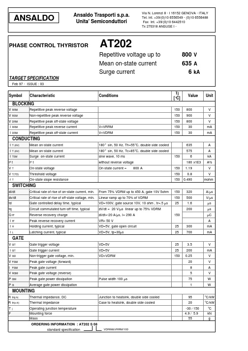
Junction to heatsink, double side cooled Case to heatsink, double side cooled
95 20 -30 / 150 4.9 / 5.9 55
°C/kW °C/kW °C kN g
VDRM&VRRM/100
元器件交易网
From 75% VDRM up to 450 A, gate 10V 5ohm Linear ramp up to 70% of VDRM VD=100V, gate source 10V, 10 ohm , tr=.5 µs dV/dt = 20 V/µs linear up to 75% VDRM di/dt=-20 A/µs, I= 290 A VR= 50 V VD=5V, gate open circuit VD=5V, tp=30µs
VD=5V VD=5V VD=VDRM
25 25 150
3.5 200 0.25 20 8 5
V mA V V A V W W
Pulse width 100 µs
75 1
MOUNTING
R R T F
th(j-h) th(c-h) j
Thermal impedance, DC Thermal impedance Operating junction temperature Mounting force Mass ORDERING INFORMATION : AT202 S 08 standard specification
Characteristic
Conditions
Tj [°C]
150 150 150
Value
Unit
BLOCKING
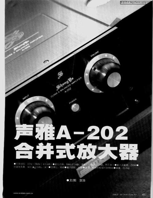
声雅A-202合并式放大器
一 点 毫 . 弗蟊翟
誊
— —
A
一
l
— . i -
r
r
1
● ・ 。
I I [ 。 一 } 。
■ 】 l i - I r i _ . ■ ■
I ■ ■●d I
● 窭 响 应 1C ~ №
可 以 毫 不 夸 张 地 说 ,声 雅 的A一2 1 后 续 的A一 0和 2 2 笔 者 所 见 、在 外 观 造 型 上 最 具 个 性 的 国 产 音 0是
响。
甲般 硬 朗 的 机 身 , 也借 助 于 铝 色 的 机 角 予 以配 衬 ;黑
白相 间的音 量 和讯 源 旋钮 在 看 似平 面 的面 板上 “ 制 造 ” 出 更 为 立 体 的 视 觉 效 果 ;就 连 位 于 下 方 的 显 示
如 果 单 纯 以 面 板 的 局 部 来 打 量 ,甚 至 有 人 会 将 它 与 另一 知 名Hi E d 大 器 品牌 所 混 淆 。记 得 笔 者 曾于 - n ̄
屏 ,也通 过 这 种 斜 置 的 方 式 来 调 整 角度 呈 现 出 它 的 与 众 不 同 。 种 种 配 搭 ,让 被 誉 为 永 不 落 伍 的 黑 色 显 得
,
-r ,
尊借理失真
≤a1 &
●文/ 图
贺浩
ww w avst e n at COr cn
29 V5 t c t 06 A te f e r 5 o Al h
41
维普资讯
记得还是去年J 月,通过 瑰 代音响技. J 术》上启宁先生的测 i文章让笔者 乎
设 计 理 念 沿 袭 了之 前A一 0 的 成 熟 经验 , 而 区 别 仅 仅 21 质。
AM-167 202 242 282 322 零件手册说明书

Cuttin AM- AM- AM- AM167 202 242 282 322
Notes
X X X X X M10 X 16 X X X X X B 10 8 10 12 14 16 X X XX X 2 3 45 6 4 5 67 8 4 5 67 8 8 10 12 14 16 X X X X X M16 X 1.5 X X X X X 16 X 22 X 1.5 X X X X X M27 X 1.5 4 5 67 8 X X XX X X X X X X 30 X 42 X .5 X X XX X X X X X X B 10 X 8 X 25 X X X X X B 6.3 X 13 2 2 22 2 X X X X X M18 X 1.5
Mower Beam with Bearings
Mower Beam with Bearings
Item Part Number
Description
Serial # Ranges
AM- AM- AM- AM- AM167 202 242 282 322
35 139.347.0
Mower Bar Complete
250.270.0 14 139.666.0 15 144.937.2 16 908.758.0 17 139.665.0 18 144.946.2 19 906.432.1 20 904.044.0 21 937.004.0 22 145.635.1 23 937.510.0 24 145.119.7
145.120.8 139.130.1 139.131.0 139.205.0 25 145.483.0 26 904.045.1 904.047.1 27 144.346.2 30 144.533.0 35 145.565.0 145.566.0 145.567.1 145.568.0
什么是202不锈钢及国内外202不锈钢牌号 化学成分 性能对照表
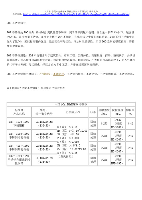
202不锈钢简介:
202不锈钢是200系列铬-镍-锰奥氏体型不锈钢,属于低镍高锰不锈钢,镍含量一般在4%以下,锰含量8%左右,是节镍型不锈钢,在性能上优于201不锈钢;在化学成分中我们可以看到,200系列不锈钢中还加入了氮(N),氮能提高钢的强度,低温韧性和焊接性,增加时效敏感性,所以200系列的强度较高、焊接性能也比较好;
202不锈钢用途:202不锈钢常用于建筑装饰,市政工程、公路护栏、宾馆设施、商场、玻璃扶手、公共设施等场所。
由高精度自动化制管设备,通过自身蚀溶焊接,翻卷成形,在无任何金属填充物下,充入气体保护(管子内外侧)焊接而成,焊接方式为TIG工艺,并作在线固溶涡流探伤。
202不锈钢常用的材料有:不锈钢板、不锈钢棒、不锈钢六角棒、不锈钢管、不锈钢焊接管、不锈钢丝等。
以下是国内外202不锈钢牌号化学成分性能对照表。
Spare parts manual Screw compressor units SAB 202说
10-1 10-2
20-1 20-2
21 22 23 24 25 26 27 28 30
40 41 42 43 44 45 46 47 48 49
60 61 62 63 64
Compressor Housing Compressor housing (L) Compressor housing (S) Bearing cover at suction end Bearing cover, female drive Bearing cover, male drive O-ring dia. 430,66 x 3,53, Inner sleeve, INA IR dia. 17/20 x 16 Washer dia. 25/16,5 x 4 Threaded plug with collar 1/2" Gasket 22/29 Cylindrical screw M16 x 60 Cylindrical screw M16 x 90 Cylindrical screw M16 x 180 Hose connection Bearing cover at discharge end Thrust cover/capacity regulating cylinder Cylinder screw M16 x 60 Washer dia. 25/16,5 x 4 O-ring dia. 151,99 x 3,53 Adjusting screw Locking screw M6 x 10 Cross bar for bearing adjustment Cylinder screw M12 x 30 Inner sleeve, INA IR dia 17/20 x 16 O-ring dia. 13,94 x 2,62 Spare parts - SAB 202 Cover for capacity regulating cylinder Cover for capacity cylinder O-ring dia. 142,47 x 3,53 Cylinder screw M12 x 35 Cylinder Screw M6x25 Gasket 17/24
MAU202中文资料

Fuse
+Vin
+Out
Dual Output DC / DC Common Converter
-Vin
-Out
Load #1 Load #2
Derating Curve
3.3, 5 & {5V Only
100
80
Output Power
60
%
40
20 0
-25
-10 0
All Other Output
Model 5V Input Models 12V Input Models 24V Input Models
All Models
Min.
4.5 10.8 21.6 ---
Typ.
Max.
5
5.5
12
13.2
24
26.4
---
0.3
Internal Capacitor
Unit
VDC A
Output Specifications
100
80
Output Power
60
%
40
20 0
-25
-10 0
Connecting Pin Patterns
(2.54 mm / 0.1 inch grids )
Single Output
-3.3% / OC
20
40
60
80
100
Ambient Temperature OC
-5% / OC
20
TOTAL POWER INT'L Tel: 877-646-0900 Fax: 978-453-7395
Email: sales@
STMicroelectronics STN202XXXUXXX TVS 电压负荷压缩器说明书
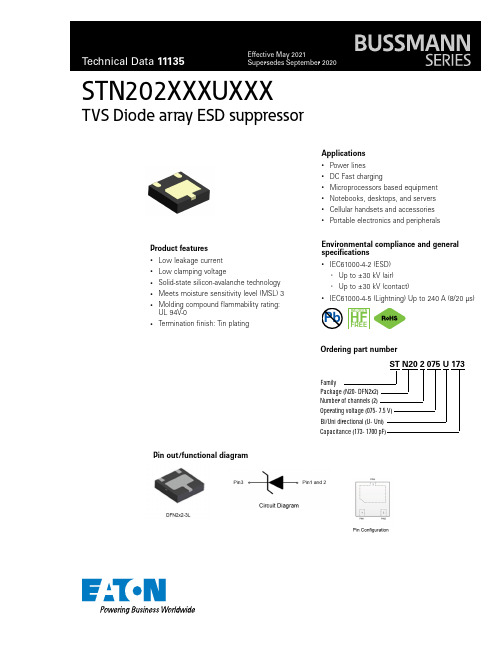
STN202XXXUXXXTVS Diode array ESD suppressorProduct features• Low leakage current • Low clamping voltage• Solid-state silicon-avalanche technology • Meets moisture sensitivity level (MSL) 3•Molding compound flammability rating: UL 94V-0•Termination finish::Tin platingApplications• Power lines • DC Fast charging• Microprocessors based equipment • Notebooks, desktops, and servers • Cellular handsets and accessories •Portable electronics and peripheralsEnvironmental compliance and general specifications•IEC61000-4-2 (ESD)•Up to ±30 kV (air)•Up to ±30 kV (contact)•IEC61000-4-5 (Lightning) Up to 240 A (8/20 µs)Pb HALOGENHFFREEST N20 2 075 U 173FamilyPackage (N20- DFN2x2)Number of channels (2)Operating voltage (075- 7.5 V) Ordering part numberBi/Uni directional (U- Uni)Capacitance (173- 1700 pF)Pin out/functional diagram2Technical Data 11135Effective May 2021STN202XXXUXXX TVS Diode array ESD suppressor/electronicsParameterSymbolValueUnitSTN202075U173STN202120U952STN202150U952STN202240U752Peak pulse power dissipation on 8/20 μs waveform P pp 5000450045006000W ESD per IEC 61000-4-2 (Air)ESD per IEC 61000-4-2 (Contact)V ESD +/-30 +/-30+/-30 +/-30+/-30 +/-30+/-30 +/-30kVLead soldering temperature T L +260 (10 seconds)+260 (10 seconds)+260 (10 seconds)+260 (10 seconds)°C Operating junction temperature range T J -55 to +125-55 to +125-55 to +125-55 to +125°C Storage temperature rangeT STG-55 to +150-55 to +150-55 to +150-55 to +150°CElectrical characteristics (+25 °C)STN202075U173ParameterTest conditionMinimumTypicalMaximumSymbol (Units)Reverse working voltage ---7.5V RWM (V)Reverse breakdown voltage I T = 1 mA 8910V BR (V)Reverse leakage current V RWM = 7.5 V --1I R (μA)Clamping voltageI PP = 50 A, t p = 8/20 μs -1315.5V C (V)I PP = 100 A, t p = 8/20 μs -15.518.5V C (V)I PP = 240 A, t p = 8/20 μs-2125V C (V)Junction capacitanceV RWM = 0 V, f = 1 MHz160017002200C J (pF)STN202120U952ParameterTest condition Minimum Typical Maximum Symbol (Units)Reverse working voltage ---12V RWM (V)Reverse breakdown voltage I T = 1 mA 1314.516V BR (V)Reverse leakage current V RWM = 12 V --1I R (μA)Clamping voltageI PP = 50 A, t p = 8/20 μs --22V C (V)I PP = 100 A, t p = 8/20 μs --25V C (V)I PP = 180 A, t p = 8/20 μs--32V C (V)Junction capacitanceV RWM = 0 V, f = 1 MHz9009501200C J (pF)STN202150U952ParameterTest condition Minimum Typical Maximum Symbol (Units)Reverse working voltage ---15V RWM (V)Reverse breakdown voltage I T = 1 mA 1617.519V BR (V)Reverse leakage current V RWM = 15 V --1I R (μA)Clamping voltageI PP = 50 A, t p = 8/20 μs -2225V C (V)I PP = 100 A, t p = 8/20 μs -2527V C (V)I PP = 150 A, t p = 8/20 μs-2935V C (V)Junction capacitanceV RWM = 0 V, f = 1 MHz-9501200C J (pF)Absolute maximum ratings(+25 °C, RH=45%-75%, unless otherwise noted)3Technical Data 11135Effective May 2021STN202XXXUXXXTVS Diode array ESD suppressor /electronics STN202240U752ParameterTest condition Minimum Typical Maximum Symbol (Units)Reverse working voltage ---24V RWM (V)Reverse breakdown voltage I T = 1 mA 262730V BR (V)Reverse leakage current V RWM = 24 V --1I R (μA)Clamping voltageI PP = 50 A, t p = 8/20 μs -4550V C (V)I PP = 120 A, t p = 8/20 μs-5260V C (V)Junction capacitanceV RWM = 0 V, f = 1 MHz-750-C J (pF)Mechanical parameters, pad layout- mmDimension Minimum Typical MaximumA 0.510.550.60A10.000.020.05A3 0.15 REFb 0.250.300.35D 1.90 2.00 2.10E 1.90 2.00 2.10D20.85 1.00 1.10E2 1.35 1.50 1.60e 1.20 1.30 1.40H 0.200.250.30K 0.200.300.40L 0.350.400.45R0.15--Part markingLand pattern(STN202075U173)(STN202150U952)(STN202120U952)4Technical Data 11135Effective May 2021STN202XXXUXXX TVS Diode array ESD suppressor/electronicsPackaging information (mm)Drawing not to scale.Supplied in tape and reel packaging, 3,000 parts per 7” diameter reel (EIA-481 compliant)5Technical Data 11135Effective May 2021STN202XXXUXXXTVS Diode array ESD suppressor/electronics Pulse derating curve ESD waveformRatings and V-I characteristic curves(+25 °C unless otherwise noted)V- I curve characteristics (Uni-directional)Pulse waveform (8/20 µs)EatonElectronics Division 1000 Eaton Boulevard Cleveland, OH 44122United States/electronics © 2021 EatonAll Rights Reserved Printed in USAPublication No. 11135May 2021STN202XXXUXXX TVS Diode array ESD suppressorTechnical Data 11135Effective May 2021Life Support Policy: Eaton does not authorize the use of any of its products for use in life support devices or systems without the express writtenapproval of an officer of the Company. Life support systems are devices which support or sustain life, and whose failure to perform, when properly used in accordance with instructions for use provided in the labeling, can be reasonably expected to result in significant injury to the user.Eaton reserves the right, without notice, to change design or construction of any products and to discontinue or limit distribution of any products. Eaton also reserves the right to change or update, without notice, any technical information contained in this bulletin.Solder reflow profileT e m p e r a t u r eT LT PEaton is a registered trademark.All other trademarks are property of their respective owners.Follow us on social media to get the latest product and support information.Reference J-STD-020Profile featureStandard SnPb solderLead (Pb) free solderPreheat and soak • Temperature min. (T smin )100 °C 150 °C • Temperature max. (T smax )150 °C 200 °C • Time (T smin to T smax ) (t s )60-120 seconds 60-120 seconds Ramp up rate T L to T p 3 °C/ second max. 3 °C/ second max.Liquidous temperature (T l ) Time (t L ) maintained above T L183 °C60-150 seconds 217 °C60-150 seconds Peak package body temperature (T P )*Table 1Table 2Time (t p )* within 5 °C of the specified classification temperature (T c )20 seconds*30 seconds*Ramp-down rate (T p to T L ) 6 °C/ second max. 6 °C/ second max.Time 25 °C to peak temperature6 minutes max.8 minutes max.* Tolerance for peak profile temperature (T p ) is defined as a supplier minimum and a user maximum.Table 1 - Standard SnPb solder (T c )Package thicknessVolume mm3 <350Volume mm3 ≥350<2.5 mm 235 °C 220 °C ≥2.5 mm220 °C220 °CTable 2 - Lead (Pb) free solder (T c )Package thicknessVolume mm 3 <350Volume mm 3350 - 2000Volume mm 3 >2000<1.6 mm 260 °C 260 °C 260 °C 1.6 – 2.5 mm 260 °C 250 °C 245 °C >2.5 mm250 °C245 °C245 °C。
PGA202 PGA203 中文数据手册
PGA202 PGA203 中文数据手册By Hi_Cracker @whu数控仪表放大器PGA202/PGA203FEATURES1,数字可编程增益:1),十进制模式的PGA202 增益可编程为1,10,100,1000。
2),二进制模式的PGA203 增益可编程为1,2,4,82,较低的偏置电流:最大偏置电流为50pA。
3,快速的建立时间:2us之内可达到0.01%4,非常低的非线性度:最大0.012%。
5,高共模抑制比:最小可达80dB6,使用新的跨导电路,降低系统成本。
APPLICATIONS数据采集系统自动调整电路动态的扩展范围远程仪表测试设备DESCRIPTIONPGA202是一个数字可控增益的单片仪表放大器,其增益可以调节为1,10,100,1000。
PGA203与之类似,只是提供的增益档位不同,其增益档位是1,2 ,4,8。
为了方便与微处理器的对接,两者都提供了与TTL或CMOS相兼容的输入端口。
两者都具有FET输入和一个新的跨导电路,这样保持了几乎恒定的增益带宽。
增益和偏移量都是经过激光修整的,使用者使用无需接任何外部元件。
这两款放大器有陶瓷和塑料两种封装形式。
陶瓷封装主要应用与工业应用场合,而塑料封装主要应用与商业,二者的温度适用范围不同。
ABSOLUTE MAXIMUM RATINGS供电电压................................................................................... ±18V内部功率耗散............................................... .............. 750MW模拟和数字输入.............................................. ....... ±(VCC+ 0.5V)工作温度范围:G封装................................................ ............... -55°C至+125°CP封装................................................ ............... -40°C至+100°C。
Raychem 202F263-51-0 直角形热纤列胶包套说明书
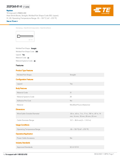
202F263-51-0Heat Shrink Boots, Straight, Molded Part Shape Code 202, Lipped, 51, 20, OperatingTemperature Range -55 – 135 °C [-67 – 275 °F]Harnessing>Heat Shrink Components>Heat Shrink BootsMaterial Systems Code:20Material Code:51Lipped:YesMolded Part Shape Code:202Molded Part Shape:StraightFeaturesProduct Type FeaturesMolded Part Shape StraightConfiguration FeaturesLipped YesBody FeaturesMaterial Code51Material Systems Code20Adhesive Pre-Coat NoMaterial Modified Fluoro-ElastomerDimensionsWire/Cable Outside Diameter.55 in, .63 in, .7 in, .71 in, .787 in, .87 in, 14mm, 16 mm, 18 mm, 20 mm, 22 mm Cable Diameter Range12.7 – 38.4 mm[.5 – 1.512 in]Usage ConditionsOperating Temperature Range-55 – 135 °C[-67 – 275 °F]Operation/ApplicationPower Cable Accessory NoIndustry StandardsApproved Standards SC-X-15112202F263-51-0 ACTIVERaychemTE Internal #:298805-000Heat Shrink Boots, Straight, Molded Part Shape Code 202, Lipped,51, 20, Operating Temperature Range -55 – 135 °C [-67 – 275 °F]View on >Government Qualified NoOtherMolded Part Shape Code202Fluid/Chemical Resistance Suitable for long term fluid immersion &elevated temperatures including fuel Adhesive Options/86 PrecoatAdhesive Type Adhesive Purchased SeparatelyProduct ComplianceFor compliance documentation, visit the product page on >EU RoHS Directive 2011/65/EU CompliantEU ELV Directive 2000/53/EC CompliantChina RoHS 2 Directive MIIT Order No 32, 2016No Restricted Materials Above ThresholdEU REACH Regulation (EC) No. 1907/2006Current ECHA Candidate List: JUN 2020(209)Candidate List Declared Against: JAN 2020(205)Does not contain REACH SVHCHalogen Content Not Low Halogen - contains Br or Cl > 900ppm.Solder Process Capability Not applicable for solder process capabilityProduct Compliance DisclaimerThis information is provided based on reasonable inquiry of our suppliers and represents our current actual knowledgebased on the information they provided. This information is subject to change. The part numbers that TE has identified asEU RoHS compliant have a maximum concentration of 0.1% by weight in homogenous materials for lead, hexavalentchromium, mercury, PBB, PBDE, DBP, BBP, DEHP, DIBP, and 0.01% for cadmium, or qualify for an exemption to theselimits as defined in the Annexes of Directive 2011/65/EU (RoHS2). Finished electrical and electronic equipment productswill be CE marked as required by Directive 2011/65/EU. Components may not be CE marked. Additionally, the partnumbers that TE has identified as EU ELV compliant have a maximum concentration of 0.1% by weight in homogenousmaterials for lead, hexavalent chromium, and mercury, and 0.01% for cadmium, or qualify for an exemption to these limitsas defined in the Annexes of Directive 2000/53/EC (ELV). Regarding the REACH Regulation, the information TE provideson SVHC in articles for this part number is based on the latest European Chemicals Agency (ECHA) ‘Guidance onrequirements for substances in articles’ posted at this URL: https://echa.europa.eu/guidance-documents/guidance-on-reachCompatible PartsTE Model / Part #262062-00181044/6-4-9TE Model / Part #CW0974-000TXR54AZ00-1004BITE Model / Part #819102-000301A513-51-0TE Model / Part #819119-000202F253-51-0TE Model / Part #819118-000202F242-51-0TE Model / Part #819117-000202F232-51-0TE Model / Part #585839-000562A067-25/86-0TE Model / Part #138458-000TXR54AB90-0804AITE Model / Part #483859-000TXR15AB00-1008AITE Model / Part #819101-000301A512-51-0TE Model / Part #CJ2087-000HL2010E-KIT-120VTE Model / Part #890103-000S1124-TAPE-0.75X100-FTCustomers Also BoughtDocumentsProduct Drawings202F263-51-0EnglishDatasheets & Catalog Pages1654025_Sec4_-51EnglishRaychem Molded Parts Visual GuideEnglishProduct Specifications Product Specification English。
202化学成分
202化学成分
摘要:
1.引言
2.202 的化学成分及其性质
3.202 化学成分的应用领域
4.结论
正文:
【引言】
202,即不锈钢,是一种具有良好耐腐蚀性的合金材料。
其之所以具有良好的耐腐蚀性,主要源于其独特的化学成分。
本文将对202 的化学成分及其性质进行详细介绍,并探讨其在各个领域的应用。
【202 的化学成分及其性质】
202 不锈钢的主要化学成分包括:碳(C)≤0.15%,硅(Si)≤1.00%,锰(Mn)≤2.00%,磷(P)≤0.035%,硫(S)≤0.030%,铬(Cr)
17.00%-20.00%,镍(Ni)8.00%-11.00%。
这些元素的组合使得202 不锈钢具有良好的耐腐蚀性、抗氧化性、高温性能和良好的焊接性能。
【202 化学成分的应用领域】
202 不锈钢广泛应用于各个领域,例如:
1.餐饮行业:202 不锈钢具有良好的耐腐蚀性和抗氧化性,使得它成为制作厨房用具、餐具等食品接触材料的理想选择。
2.建筑装饰:202 不锈钢因其美观、耐用的特性,在建筑装饰领域有着广
泛的应用,如豪华酒店、大型商场、高级品牌专卖店等。
3.医疗设备:202 不锈钢的抗腐蚀性能使其在制造医疗器械中具有广泛的应用,如手术器械、注射器等。
4.化学、石油、纸浆等工业设备:202 不锈钢在化学、石油、纸浆等工业设备中有着广泛的应用,因为它可以抵抗各种腐蚀介质的侵蚀。
5.高温环境下的应用:202 不锈钢在高温环境下具有良好的性能,可用于制造锅炉、热交换器等高温设备。
【结论】
202 不锈钢的独特化学成分使其在各个领域都具有广泛的应用。
202不锈钢规格
202不锈钢规格一、202不锈钢简介202不锈钢是一种广泛使用的奥氏体不锈钢,它在多个领域都有广泛的应用,尤其是在建筑、家具和汽车行业。
它的高耐腐蚀性和美观的表面使它成为一种理想的材料选择。
然而,与所有不锈钢种类一样,了解其规格和特性是至关重要的,以确保其使用时能够满足特定的需求。
二、202不锈钢的化学成分202不锈钢主要由铁、铬、镍等元素组成,其化学成分如下:●铁(Fe):作为基体元素,提供了强度和硬度。
●铬(Cr):增强耐腐蚀性,一般含量不少于18%。
●镍(Ni):有助于保持不锈钢的奥氏体结构,增加韧性和延展性。
●锰(Mn):通常含量在5%-14%之间,用于提高强度和耐腐蚀性。
●硅(Si):有助于提高热处理过程中的稳定性。
●磷(P)和硫(S):通常控制在较低水平,以减少脆性。
此外,可能还包含少量的碳(C)、氮(N)和其他微量元素。
三、202不锈钢的物理性能●密度:大约为7.93 g/cm³。
●热膨胀系数:在温度升高时,材料的尺寸会发生变化。
202不锈钢的热膨胀系数约为10.0×10^-6 K^-1。
●导热性:中等导热性,适合于需要一定保温性能的应用。
●磁性:与304不锈钢相比,202不锈钢具有相对较低的磁导率。
四、202不锈钢的力学性能●抗拉强度:根据不同的处理和规格,抗拉强度可以从480 MPa到620 MPa不等。
●屈服点:在受到外力时,材料开始永久变形的点。
对于202不锈钢,屈服点通常在170-350 MPa之间。
●延伸率:衡量材料在受到外力时的可延展性。
202不锈钢具有良好的延展性,延伸率通常大于40%。
●硬度:可通过不同的热处理工艺进行调节。
常用的硬度指标如洛氏硬度(HRB)和维氏硬度(HV)用于描述其硬度和韧性之间的关系。
五、202不锈钢的规格与用途1.规格:根据不同的应用需求,202不锈钢板材、管材和棒材都有多种规格。
常见的产品形式包括薄板、厚板、带材、管材和棒材等。
- 1、下载文档前请自行甄别文档内容的完整性,平台不提供额外的编辑、内容补充、找答案等附加服务。
- 2、"仅部分预览"的文档,不可在线预览部分如存在完整性等问题,可反馈申请退款(可完整预览的文档不适用该条件!)。
- 3、如文档侵犯您的权益,请联系客服反馈,我们会尽快为您处理(人工客服工作时间:9:00-18:30)。
1
Caution: Device contains Beryllium Oxide
* Stresses in excess of the absolute maximum ratings can cause permanent damage to the device. These are absolute stress ratings only. Functional operation of the device is not implied at these or any other conditions in excess of those given in the operational sections of the data sheet. Exposure to absolute maximum ratings for extended periods can adversely affect device reliability.
Features
- Gold Metalized - Internally matched to 50 Ohms - Caccadeable - Wide dynamic range
Symbol
Ga Delta Ga P1dB VSWR Vdc Delta Tjf NF IP3 T Oper. T Stor.
ELECTRICAL CHARACTERISTICS at Tcase = 25 Deg C. Typ. Max. Units Test Conditions Characteristics Min.
Small signal Gain Gain Flatness Pout @ 1dB Comp. Input Mismatch Operating voltage Temp. Rise Junction to Flange Noise Figure 3rd Order Intercept Operating Temp. Storage Temp -55 -55 14.0 +30 12.0 13.0 +/- 0.5 +32 1.5:1 15.0 +50 5.0 +50 +125 +150 2.0:1 16.0 Volts C dBm dBm Deg C Deg C Freq = 70MHz Idc = 350mA Freq = 30 MHz Idc = 350mA +/- 1 dBm dB dBm Freq = 1 -200MHz Idc = 350mA
元器件交易网
AUNA-202 1.0 W 14-16 Volts, DC- 200MHz
Introduction
The AUNA-202 is a 50 Ohm hybrid amplifier module designed for broadband operation in Class A amplifier driver applications operating from DC to 200MHz. Its wide dynamic range and flexibility make it ideal for a broad spectrum of instrurmentation, receiver, and transmitter applications.
元器件交易网www.cecቤተ መጻሕፍቲ ባይዱ
AUNA-202 1.0 W 14-16 Volts, DC- 200MHz
2
