usepa 9056a
深圳市自主创新产品XXXX
固高GU嵌入式运动控制器 健儿清解液 百安洗液、 网络视频服务器 E-NVS嵌入式网络视频系统 室外高速球机 ST-CC8239/CC8309 室外高速球机 ST-CC8139C/STCC8269/ST-CC8369/ST-CC8 网络高速球型摄像机 室外高速球 彩色摄像机 PT7200对讲机 联想成全T468服务器 联想昭阳E23笔记本电脑 联想Think centre M台式电脑 联想黑白激光多功能一体机M3220 联想彩色激光打印机C8200N 联想昭阳K43笔记本电脑 联想黑白A4激光打印机LJ3500 联想黑白A4激光打印机LJ3550DN 联想昭阳E43笔记本电脑 联想黑白A4激光打印机LJ2200L 联想万全R520服务器 联想黑白激光多功能一体机M7250N 联想数字投影机C21 联想数字投影机T07 联想黑白激光多功能一体机M7260 联想昭阳K23笔记本电脑 联想万全R525服务器
4
21
深圳华昌视数字技术有限公司
公交智能综合信息系统产品
公交智能综合信息系统产品(型号:无线数字电视快速恢复播放 的装置);公交智能综合信息系统产品(型号:无线数字电视黑屏 检测上报的装置);公交智能综合信息系统产品(型号:无线数字 电视无声检测上报的装置);公交智能综合信息系统产品(型号: 无线数字电视故障自动报修装置);公交智能综合信息系统产 品(型号:移动电视车载监控终端软件);公交智能综合信息系统 产品(型号:移动电视终端管理软件) 第二代居民身份证阅读(验证)机具IC卡读写器(型号:CVR100) 基于SDH的多业务传送节点(MSTP)设备(型号:Carrywave600 、Carrywave2500) PCM设备(型号:KB-6900)
艾默生网络能源有限公司
NETSURE 801 大容量电源系统
Amprobe UAT-600地下设施定位器系列用户说明书

Accidentally hitting a utility line during a project can lead to costly repairs and create hazardous public safety situations. Digging in the wrong place can also lead to unnecessary delays and costs for your project, and ultimately, your company. Avoid this disruption with the rugged and durable Amprobe UAT-600 Series, designed to accurately pinpoint underground utilities and buried services up to 20 feet deep.Designed for electricians with a CAT IV 600 V rating, the locating kits come complete and ready for use with a Transmitter, Receiver, test lead kit, batteries and additional fuses, all in a mobile, protective duffle bag.The UAT-620 kit also includes a Signal Clamp for transmitting a signal when it is not possible to make electrical contact with the cable to be traced. For applications where ground fault locating is required, use the UAT-600 Transmitter in combination with the optional A-Frame accessory.Intuitive Transmitter automatically chooses the correct locatingfunctionSC-600 Signal Clamp included in the UAT -620 KitLarge LCD Display with auto backlight for clear viewing in full sunlightLocateunderground utilities up to 20 ft.UAT -600 SeriesUnderground Utilities LocatorAccurately and safely pinpoint underground utilities before you digUAT -620Underground Utilities Locator KitAF-600 A-Frame Accessory*Ground Fault FinderSee page 2 for specifications* (Not included in the UAT-610 and UAT-620 Kits)Safety CertificationAll Amprobe tools, including the Amprobe UAT-600 Series, are rigorously tested for safety, accuracy, reliability, and ruggedness in our state-of-the-art test lab. In addition, Amprobe products that measure electricity are listed by a 3rd party safety lab, either UL or CSA. This system assures that Amprobe products meet or exceed safety regulations and will perform in a tough, professional environment formany years to come.Features and Highlights• Multiple tracing modes allow you to locate and trace energized and de-energized utilities in a variety of applications• The intuitive Transmitterautomatically chooses the correctlocating function based on the connectedaccessory and includes selectable 8/33kHz frequencies• The Receiver’s high-contrast display allows for clear viewing in full sunlight and features an automatic backlight for shaded and dark areas• Rated CAT IV 600 V , ensuring safety when working with energized cables • Semi-automatic gain control quickly detects tracing signal and allows precise adjustment of the receiver sensitivity• Accurate depth measurement to 20 ft• Rugged, durable construction: water and dust resistant to IP54 and drop proof to 3.28 ft (1 m)• Use the Signal Clamp to induce asignal without making electrical contact (UAT -620)• Ground fault locating with the optional A-Frame accessory • Comes as a complete kit, ready for useLCD Display with autobacklightDetect ground faults on cables and pipesAF-600-A-FrameGround Fault FinderAF-600 A-FrameGround Fault FinderSave time and money by pinpointing leakage pointsGround faults are a common problem with electrical cables. Find any fault with the AF-600 A-Frame cable ground fault finder, specifically designed for use with the Amprobe UAT -600 Series.Set up the UAT -600-T Transmitter to apply a fault find signal to the utility under test, the AF-600 A-Frame receives the signal and locates the place of the fault. The AF-600 will pinpoint where a cable metal conductor (either a sheath or a metallic conductor of the wire) touches the ground and can also detect other conductors to ground faults such as pipeline coating defects.Carrying Case, User ManualThe AF-600 comes complete with batteries and a carrying caseFeatures and Highlights • Identify any point of leakage around a cable • Locate cable and wire ground faults, sheath faults or pipeline coating defects, where the utility is in direct contact with the ground • Find the exact point where metal is touching the ground and power is leaking, ie, a shield is rusted or a rubber buffer is broken, creating noise on a cable • Advanced technology and digital signal processing makes pinpointing process fast, accurate and clear:-Compass guidance with numeric fault field strength indicates the direction of the fault -Distance sensitive left and right arrows guides the user to precisely follow the path of the buried utility-Automatic gain control quickly detects tracing signal and precisely adjusts the A-Frame sensitivity-Adjustable volume controlsClearly view the LCD display in bright sunlightPinpoint fault location by using the AF-600 with the UAT-600 TransmitterSC-600Signal ClampTL-UAT -600Test Leads KitSC-600 Signal Clamp(included in the UAT -620 Kit only)The Signal Clamp accessory provides an efficient and safe method of applying a locate signal to a cable, enabling the Transmitter to induce a signal through the insulation into the wires or pipes. The clamp works on low impedance closed circuits only.Test Leads Kit(included in the UAT -610 and UAT -620 Kits)TL-UAT -600 Test Leads Kit includes: Black test lead with detachable black alligator clip, Red test lead with permanently attached red alligator clip, Ground stakeTrace an individual utility by connecting the The Transmitter will automatically change modes The Receiver’s high contrast LED screen is easy toUAT-620 Underground Utilities Locator Kit。
AY-U系列爆炸防护形状适配器商品说明书

‘Y’ (Exd/Exe) adaptors - AY-U SeriesY adaptorDimensionsMaterials• Brass CZ121• 316 stainless steel • Mild steel • AluminiumPlating options• Electroless nickel • Zinc • Chromated• Others on applicationThreadforms• Metric • NPTType AY-UMale size Female size A (max.) B (max.)Angle between entries (D)M16M1665.0075.00120°M20M2065.0075.00120°M25M2567.0078.00120°M32M3270.0081.00120°M40M4089.00102.00120°M50M50104.00120.00120°M63M63131.00151.00120°M75M75153.00177.00120°⅜" NPT ⅜" NPT 65.0075.00120°½” NPT ½” NPT 65.0075.00120°¾” NPT ¾” NPT 67.0078.00120°1” NPT 1” NPT 78.0090.00120°1¼” NPT 1¼” NPT 89.00102.00120°1½” NPT 1½” NPT 104.00120.00120°2” NPT 2” NPT 131.00151.00120°2½” NPT2½” NPT153.00177.00120°Redapt AY-U series of explosion-proof shaped adaptors provide an opportunity for installers to run cables in additional entries where pre-machine entries are limited or at an angle in confined or difficult situations.Compared to traditional methods of creating additional entries in enclosures Redapt shaped adaptors can reduce downtime from three weeks to one hour and total cost by half.Available in brass, aluminium, mild steel and stainless steel 316L, the AY-U series provides extra means of connection where space is limited and maintains Ex certification while matching various threadforms.Download certificates and documents hereT echnical specificationsCode of protection categories ATEX: I M2, II 2 GDIECEx: Ex db I/IIC Mb/Gb, Ex eb I/IIC Mb/Gb, Ex tb IIIC Db Compliance standardsATEX: EN 60079-0, EN 60079-1, EN 60079-7, EN 60079-31IECEx: IEC 60079-0, IEC 60079-1, IEC 60079-7, IEC 60079-31Certificate details ATEX: ITS16ATEX101340U IECEx: IECEx ITS 16.0015U EAC: RU C-GB. M43.B.01715INMETRO: NCC 18.0133 X T emperature -60°C to +200°C Ingress protection (IP):IP64 when fitted without sealing washer. IP66/IP68 when fitted with washer or thread sealant according to manufacturer’s instructions Part number:Please refer to part numbering system belowDigits 1 & 2Digit 3Digit 4Digit 5Digits 6 & 7 Digits 8 & 9AY -U- 2 -2- 29 - 04ExampleProduct Digits 1 & 2‘Y’ Exd/Exe AYADAPTORAdaptor Exd/e certifiedMild steelZinc1/2’’ NPT (male)‘Y’ (Exd/Exe) adaptors - Product codingNotes:- Always quote male thread first.- Threadform codes below to be used for both male and female threads.M20(female)Certification Digit 3UExd I and IIC & Exe I and IICMaterial Digit 41 Brass2 Mild steel 3Stainless steel5 AluminiumPlating Digit 50 Unplated 1Electroless nickel2 Zinc 6 ChromatedDigits 6 & 7, Male thread – Digits 8 & 9, Female threadMetric ETNPT NPSM ISO pipeISO pipe PGimperial conduitparallel (BSPP) taper (BSPT)03 M 16 17 5⁄8” ET 29 1⁄2” NPT 42 1⁄2” NPSM 55 1⁄2” BSPP 68 1⁄2” BSPT 79 P G704 M 20 18 3⁄4” ET 30 3⁄4” NPT 43 3⁄4” NPSM 56 3⁄4” BSPP 69 3⁄4” BSPT 80 P G905 M 25 19 1” ET 31 1” NPT 44 1” NPSM 57 1” BSPP 70 1” BSPT 81 P G1106 M 32 20 11⁄4” ET 32 11⁄4” NPT 45 11⁄4 ” NPSM 58 11⁄4” BSPP 71 11⁄4” BSPT 82 P G13.507 M 40 21 11⁄2” ET 33 11⁄2” NPT 46 11⁄2” NPSM 59 11⁄2” BSPP 72 11⁄2” BSPT 83 P G1608 M 50 22 2” ET 34 2” NPT 47 2” NPSM 60 2” BSPP 73 2” BSPT 84 P G2109 M 63 23 21⁄2” ET 35 21⁄2” NPT 48 21⁄2” NPSM 61 21⁄2” BSPP 74 21⁄2” BSPT 85 P G2910 M 7524 3” ET36 3” NPT49 3” NPSM62 3” BSPP75 3” BSPT86 P G36For other thread options, please contact us.Thread dimension chartISO metricBS 3643 1.5mm pitchSize Major dia. TPI M12 11.97 16.93 M16 15.97 16.93 M20 19.97 16.93 M25 24.97 16.93 M32 31.97 16.93 M40 39.97 16.93 M50 49.97 16.93 M63 62.97 16.93 M75 74.97 16.93 2.0mm pitchM80 79.97 12.70 M85 84.97 12.70 M90 89.97 12.70 M100 99.97 12.70 M110 109.97 12.70 M120 119.97 12.70NPTANSI.ASME B1.20.1Size Pipe dia. TPI1⁄2” 21.34 14.003⁄4” 26.67 14.001” 33.40 11.5011⁄4” 42.16 11.5011⁄2” 48.26 11.502” 60.33 11.5021⁄2” 73.03 8.003” 88.90 8.0031⁄2” 101.60 8.004” 114.30 8.00PGDIN 40430Size Major dia. TPIPG7 12.50 20.00PG9 15.20 18.00PG11 18.60 18.00PG13.5 20.40 18.00PG16 22.50 18.00PG21 28.30 16.00PG29 37.00 16.00PG36 47.00 16.00PG42 54.00 16.00PG48 59.30 16.00Alternate ISO pipe thread designationsUK BSP P arallel or T aperBS2279 (BS21)Europe G (Parallel) GK (Taper)R (Parallel) RK (Taper)Japan PF (Parallel) JIS B 303CIS K mpy (Taper)BSP ISO pipe threadISO R/7; UNI 6125Size Pipe Dia. TPI3⁄8” 16.66 19.001⁄2” 20.96 14.003⁄4” 26.44 14.001” 33.25 11.0011⁄4” 41.91 11.0011⁄2” 47.80 11.002” 59.61 11.0021⁄2” 75.18 11.003” 87.88 11.00ET imperial conduitBS31Size Major dia. TPI5⁄8” 15.88 18.003⁄4” 19.05 16.001” 25.40 16.0011⁄4” 31.75 16.0011⁄2” 38.10 14.002” 50.80 14.0021⁄2” 63.50 14.003” 76.20 14.00Thread dimension substitution chartMetric NPT (or NPS) PG BSP ISO Pipe ET M16 – 7, 9 – 5⁄8”M20 1⁄2” 11, 13.5 1⁄2” 3⁄4”M25 3⁄4” 16 3⁄4” 1”M32 1” 21 1” 11⁄4”M40 11⁄4” 29 11⁄4” 11⁄2”M50 11⁄2” 36 11⁄2” 2”M63 2” 42, 48 2” 21⁄2”M75 21⁄2” – 21⁄2” 3”M90 x 2.0 3” – 3” –M100 x 2.0 31⁄2” – – –M110 x 2.0 – – – –M120 x 2.0 – – – –Part numbering systemCodesPage No. Product Digits 1 & 2Adaptors and reducers14-17 AD Adaptor14-17 RD Reducer18 TA Swivel - in-line male to female 18 TC Swivel - in-line female to female 18 TD Swivel - in-line male to male18 TP Swivel - 90° male to female18 TQ Swivel - 90° female to female18 TR Swivel - 90° male to male19 AY ‘Y’ adaptor20 AT ‘T’ adaptor21 AR 90° adaptor22 AM Male to male adaptor23 AF Female to female adaptor24-25 DB Insulated adaptorStopping Plugs26-27 PD Dome head plug28 PA Type A plug28 PB Type B plugBreather Drains31 DP Breather drain (Exe)32 BD Breather drain (Exde) Other products34 UN Union - male to female34 UF Union - female to female35 AE Earth lead adaptor ExampleDigits 1 & 2 Digit 3 Digit 4 Digit 5 Digits 6 & 7 Digits 8 & 9 AD - U - 1 - 1 - 29 - 04 Adaptor Exd/e Brass Nickel- 1⁄2” NPT M20 certified plated (male) (female) Always quote male thread first.Certification Digit 3U Exd I and IIC & Exe I and IICD Exd I and IICE Exe I and IICF Industrial (marked product)Material Digit 41Brass2 Mild steel3 Stainless steel4 Glass filled nylon5 Aluminium6 Nylon 67 Red fibrePlating Digit 50 Unplated1 Electroless nickel2 Zinc6 Chromated。
DS-2XS6A46G1 P-IZS C36S80 4 MP ANPR 自动 Number Plat

DS-2XS6A46G1/P-IZS/C36S804 MP ANPR Bullet Solar Power 4G Network Camera KitIt can be used in the areas that are not suitable for laying wired network and electric supply lines, or used for the scenes that feature tough environment and have high demanding for device stability. It can be used for monitoring the farms, electric power cables, water and river system, oil pipelines and key forest areas.It also can be used in the temporary monitoring scenes, such as the large-scale competitions, the sudden public activity, the temporary traffic control and the city construction.Empowered by deep learning algorithms, Hikvision AcuSense technology brings human and vehicle targets classification alarms to front- and back-end devices. The system focuses on human and vehicle targets, vastly improving alarm efficiency and effectiveness.⏹ 80 W photovoltaic panel, 360 Wh chargeable lithium battery⏹ Clear imaging against strong back light due to 120 dB trueWDR technology⏹ Focus on human and vehicle targets classification based ondeep learning⏹Support battery management, battery display, batteryhigh-low temperature protection, charge-dischargeprotection, low-battery sleep protection and remotewakeup ⏹ LTE-TDD/LTE-FDD/WCDMA/GSM 4G wireless networktransmission, support Micro SIM card⏹Water and dust resistant (IP66) *The Wi-Fi module of this product only supports AP mode on Channel 11, and does not support other modes and channels.FunctionRoad Traffic and Vehicle DetectionWith embedded deep learning based license plate capture and recognition algorithms, the camera alone can achieve plate capture and recognition. The algorithm enjoys the high recognition accuracy of common plates and complex-structured plates, which is a great step forward comparing to traditional algorithms. Blocklist and allowlist are available for plate categorization and separate alarm triggering.SpecificationCameraImage Sensor 1/1.8" Progressive Scan CMOSMax. Resolution 2560 × 1440Min. Illumination Color: 0.0005 Lux @ (F1.2, AGC ON), B/W: 0 Lux with light Shutter Time 1 s to 1/100,000 sLensLens Type Auto, Semi-auto, ManualFocal Length & FOV 2.8 to 12 mm, horizontal FOV 107.4° to 39.8°, vertical FOV 56° to 22.4°, diagonal FOV 130.1° to 45.7°8 to 32 mm, horizontal FOV 40.3° to 14.5°, vertical FOV 22.1° to 8.2°, diagonal FOV 46.9° to 16.5°Iris Type Auto-irisLens Mount All In One LensAperture 2.8 to 12 mm: F1.2, 8 to 32 mm: F1.6 DORIDORI 2.8 to 12 mm:Wide: D: 60.0 m, O: 23.8 m, R: 12.0 m, I: 6.0 m Tele: D: 149.0 m, O: 59.1 m, R: 29.8 m, I: 14.9 m 8 to 32 mm:Wide: D: 150.3 m, O: 59.7 m, R: 30.1 m, I: 15.0 m Tele: D: 400 m, O: 158.7 m, R: 80 m, I: 40 mIlluminatorSupplement Light Type IRSupplement Light Range 2.8 to 12 mm: Up to 30 m 8 to 32 mm: Up to 50 mSmart Supplement Light Yes VideoMain Stream Performance mode:50 Hz: 25 fps (2560 × 1440, 1920 × 1080, 1280 × 720) 60 Hz: 30 fps (2560 × 1440, 1920 × 1080, 1280 × 720) Proactive mode:50 Hz: 12.5 fps (2560 × 1440, 1920 × 1080, 1280 × 720) 60 Hz: 15 fps (2560 × 1440, 1920 × 1080, 1280 × 720)Sub-Stream Performance mode:50 Hz: 25 fps (640 × 480, 640 × 360) 60 Hz: 30 fps (640 × 480, 640 × 360) Proactive mode:50 Hz: 12.5 fps (640 × 480, 640 × 360) 60 Hz: 15 fps (640 × 480, 640 × 360)Third Stream 50 Hz: 1 fps (1280 × 720, 640 × 480) 60 Hz: 1 fps (1280 × 720, 640 × 480)Video Compression Main stream: H.264/H.265Sub-stream: H.264/H.265/MJPEGThird Stream: H.265/H.264*Performance mode: main stream supports H.264+, H.265+Video Bit Rate 32 Kbps to 8 MbpsH.264 Type Baseline Profile, Main Profile, High ProfileH.265 Type Main ProfileBit Rate Control CBR/VBRScalable Video Coding (SVC) H.264 and H.265 encodingRegion of Interest (ROI) 4 fixed regions for main streamAudioAudio Compression G.711/G.722.1/G.726/MP2L2/PCM/MP3/AAC-LCAudio Bit Rate 64 Kbps (G.711ulaw/G.711alaw)/16 Kbps (G.722.1)/16 Kbps (G.726)/32 to 192 Kbps (MP2L2)/8 to 320 Kbps (MP3)/16 to 64 Kbps (AAC-LC)Audio Sampling Rate 8 kHz/16 kHz/32 kHz/44.1 kHz/48 kHzEnvironment Noise Filtering YesNetworkSimultaneous Live View Up to 6 channelsAPI Open Network Video Interface (Profile S, Profile G, Profile T), ISAPI, SDK, ISUP, OTAPProtocols TCP/IP, ICMP, HTTP, HTTPS, FTP, DHCP, DNS, DDNS, RTP, RTSP, RTCP, NTP, UPnP, SMTP, SNMP, IGMP, 802.1X, QoS, IPv6, UDP, Bonjour, SSL/TLS, WebSocket, WebSocketsUser/Host Up to 32 users3 user levels: administrator, operator, and userSecurity Password protection, complicated password, HTTPS encryption, 802.1X authentication (EAP-TLS, EAP-LEAP, EAP-MD5), watermark, IP address filter, basic and digest authentication for HTTP/HTTPS, WSSE and digest authentication for Open Network Video Interface, RTP/RTSP over HTTPS, control timeout settings, TLS 1.2, TLS 1.3Network Storage NAS (NFS, SMB/CIFS), auto network replenishment (ANR)Together with high-end Hikvision memory card, memory card encryption and health detection are supported.Client Hik-Connect (proactive mode also supports), Hik-central ProfessionalWeb Browser Plug-in required live view: IE 10+Plug-in free live view: Chrome 57.0+, Firefox 52.0+ Local service: Chrome 57.0+, Firefox 52.0+Mobile CommunicationSIM Card Type MicroSIMFrequency LTE-TDD: Band38/40/41LTE-FDD: Band1/3/5/7/8/20/28 WCDMA: Band1/5/8GSM: 850/900/1800 MHzStandard LTE-TDD/LTE-FDD/WCDMA/GSM ImageWide Dynamic Range (WDR) 120 dBDay/Night Switch Day, Night, Auto, Schedule, Video Trigger Image Enhancement BLC, HLC, 3D DNR, DefogImage Parameters Switch YesImage Settings Saturation, brightness, contrast, sharpness, gain, white balance, adjustable by client software or web browserSNR ≥ 52 dBPrivacy Mask 4 programmable polygon privacy masks InterfaceAudio 1 input (line in), max. input amplitude: 3.3 Vpp, input impedance: 4.7 KΩ, interface type: non-equilibrium,1 output (line out), max. output amplitude: 3.3 Vpp, output impedance: 100 Ω, interface type: non-equilibriumAlarm 1 input, 1 output (max. 12 VDC, 1 A)On-Board Storage Built-in memory card slot, support microSD card, up to 256 GB, Built-in 8 GB eMMC storageReset Key YesEthernet Interface 1 RJ45 10 M/100 M self-adaptive Ethernet portWiegand 1 Wiegand (CardID 26bit, SHA-1 26bit, Hik 34bit, NEWG 72 bit) EventBasic Event Motion detection, video tampering alarm, exception (network disconnected, IP address conflict, illegal login, HDD error)Smart Event Line crossing detection, intrusion detection, region entrance detection, region exiting detection, unattended baggage detection, object removal detection, scene change detection, face detectionLinkage Upload to FTP/NAS/memory card, notify surveillance center, send email, trigger recording, trigger capture, trigger alarm output, audible warningDeep Learning FunctionRoad Traffic and Vehicle Detection Blocklist and allowlist: up to 10,000 records Support license plate recognition License plate recognition rate ≥95%GeneralPower 12 VDC ± 20%, 4-pin M8 waterproof connector1. Standby power consumption: 45 mW2. The average power consumption of 24 hours:3.5 W (4G transmission is excluded).3. The max. power consumption: 7 WMaterial Front cover: metal, body: metal, bracket: metalDimension 816.2 mm × 735.9 mm × 760 mm (32.1" × 28.9" × 29.9") (Max. size of the camera after it is completely assembled)Package Dimension 862 mm × 352 mm × 762 mm (33.9" × 13.9" × 30.0")Weight Approx. 31.885 kg (70.3 lb.)With Package Weight Approx. 25.650 kg (56.5 lb.)Storage Conditions -20 °C to 60 °C (-4 °F to 140 °F). Humidity 95% or less (non-condensing) Startup and OperatingConditions-20 °C to 60 °C (-4 °F to 140 °F). Humidity 95% or less (non-condensing)Language 33 languages: English, Russian, Estonian, Bulgarian, Hungarian, Greek, German, Italian, Czech, Slovak, French, Polish, Dutch, Portuguese, Spanish, Romanian, Danish, Swedish, Norwegian, Finnish, Croatian, Slovenian, Serbian, Turkish, Korean, Traditional Chinese, Thai, Vietnamese, Japanese, Latvian, Lithuanian, Portuguese (Brazil), UkrainianGeneral Function Anti-banding, heartbeat, mirror, flash log, password reset via email, pixel counter BatteryBattery Type LithiumCapacity 360 Wh (90 Wh for each battery)Max. Output Voltage 12.6 V Battery Voltage 10.8 VOperating Temperature Charging: -20 °C to 45 °C (-4 °F to 113 °F) Discharging: -20 °C to 60 °C (-4 °F to 140 °F)Cycle Lifetime Performance mode: 5 days, Proactive mode: 8 days, Standby mode: 80 days *in cloudy/rainy days (25 °C)Battery Life More than 500 cyclesBattery Weight Approx. 2.74 kg (6.0 lb.) (0.685 kg (1.5 lb.) for each battery) ApprovalEMC CE-EMC/UKCA (EN 55032:2015+A11:2020+A1:2020, EN 50130-4:2011+A1:2014); RCM (AS/NZS CISPR 32: 2015);IC (ICES-003: Issue 7)RF CE-RED/UKCA (EN 301908-1, EN 301908-2, EN 301908-13, EN 301511, EN 301489-1, EN 301489-52, EN 62133);ICASA: same as CE-RED;IC ID (RSS-132 Issue 3, RSS-133 Issue 6, RSS-139 Issue 3, RSS-130 Issue 2, RSS-102 Issue 5);MIC (Article 49-6-4 and 49-6-5 the relevant articles and MIC Notice No. 1299 of the Ordinance Regulating Radio Equipment)Safety CB (IEC 62368-1:2014+A11)CE-LVD/UKCA (EN 62368-1:2014/A11:2017) LOA (IEC/EN 60950-1)Environment CE-RoHS (2011/65/EU);WEEE (2012/19/EU);Reach (Regulation (EC) No 1907/2006)Protection Camera: IP66 (IEC 60529-2013)Wind resistance 12 level, up to 40 m/s wind speed resistance⏹Typical ApplicationHikvision products are classified into three levels according to their anti-corrosion performance. Refer to the following description to choose for your using environment.This model has NO SPECIFIC PROTECTION.Level DescriptionTop-level protection Hikvision products at this level are equipped for use in areas where professional anti-corrosion protection is a must. Typical application scenarios include coastlines, docks,chemical plants, and more.Moderate protection Hikvision products at this level are equipped for use in areas with moderate anti-corrosion demands. Typical application scenarios include coastal areas about 2kilometers (1.24 miles) away from coastlines, as well as areas affected by acid rain. No specific protection Hikvision products at this level are equipped for use in areas where no specific anti-corrosion protection is needed.⏹Available ModelDS-2XS6A46G1/P-IZS/C36S80 (2.8-12mm)DS-2XS6A46G1/P-IZS/C36S80 (8-32mm)Dimension。
石芯电子电子烟芯片选型

单色
/
/
/
SOT23-6
CSC948X系列
恒定平均值
可选
≥1.0
可选
可选
可选
可选
32
单色
带工厂锁
/
/
SOT23-6
CSC959X系列
恒定平均值
可选
≥0.8
可选
可选
可选
可选
32
单色
/
/
/
DFN-10
CSC958X系列
恒定平均值
可选
≥0.8
可选
可选
可选
可选
32
单色
/
/
/
DFN-8
CSC903X系列
恒定平均值
可选
≥0.6
可选
可选
/
/
5
单色
/
/
大功率
QFN8FC
CSC918X系列
恒定平均值
可选
≥1.2
可选
可选
/
/
5
单色
/
开锁/上锁气压值可选
SOT23-5
CSC919X系列
恒定平均值
可选
≥1.0
可选
可选
/
/
5
单色
/
开锁/上锁气压值可选
SOT23-5
CSC905X系列
恒定平均值
可选
≥0.8
可选
可选
/
/
5
单色
/
CSC78X系列
开关信号
高电平
≥10k
可选
2.4V
/
/
5
/
/
/
TSOT23-5
SIBA URB 系列半导体保护熔断器说明书
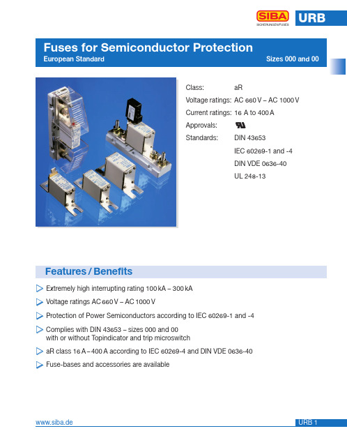
Class:aRVoltage ratings:AC 660V – AC 1000VCurrent ratings:16A to 400A Array Approvals:Standards:DIN 43653IEC 60269-1 and -4DIN VDE 0636-40UL 248-13Features/Benefits̈Extremely high interrupting rating 100kA – 300kÄVoltage ratings AC660V – AC1000V̈Protection of Power Semiconductors according to IEC 60269-1 and -4̈Complies with DIN 43653 – sizes 000 and 00with or without Topindicator and trip microswitcḧaR class 16A–400A according to IEC 60269-4 and DIN VDE 0636-40̈Fuse-bases and accessories are availableSelection Guide* Minimum operating voltage for top indicator 6.5VSize Rated Voltage Standard000AC 660 VDIN 43653Available in DC 700 V see URDC section.Size Rated Voltage Standard000AC 690/700 VDIN 43653A 2.17” (55mm)B 0.80” (20mm)C 0.33” (8.5mm)D 0.80” (20.4mm)E 3.07” (78mm)F 0.08” (2mm)I 1.54” (39mm)L (max)3.94” (100mm)Size Rated Voltage Standard000AC 660 VDIN 43653Size Rated Voltage Standard000AC 690/700 VDIN 43653A 2.17” (55mm)B 0.80” (20mm)C 0.33” (8,5mm)D 0.80” (20,4mm)E 3.07” (78mm)F 0.08” (2mm)G 2.10” (53mm)H 2.76” (70mm)I 1.54” (39mm)L (max)3.94” (100mm)Size Rated Voltage Standard00AC 660 VDIN 43653Size Rated Voltage Standard00AC 690/700 VDIN 43653A 2.17” (55mm)B 1.13” (28,8mm)C 0.40” (10,3mm)D 1.16” (29,5mm)E 3.07” (78mm)F 0.10” (2,5mm)I 1.85” (47mm)L (max) 4.13” (105mm)Size Rated Voltage Standard00AC 660 VDIN 43653A 2.17” (55mm)B 1.13” (28.8mm)C 0.40” (10.3mm)D 1.16” (29.5mm)E 3.07” (78mm)F 0.10” (2.5mm)G 2.48” (63mm)H 3.15” (80mm)I 1.54” (39mm)L (max)4.13” (105mm)Size Rated Voltage Standard00AC 690/700 VDIN 43653A 2.17” (55mm)B 1.13” (28.8mm)C 0.40” (10.3mm)D 1.16” (29.5mm)E 3.07” (78mm)F 0.10” (2.5mm)G 2.48” (63mm)H 3.15” (80mm)I 1.85” (47mm)L (max)4.13” (105mm)* 900 VacSize Rated Voltage Standard00AC 1000 VDIN 43653A 2.17” (55mm)B 1.13” (28,8mm)C 0.40” (10,3mm)D 1.16” (29,5mm)E 3.07” (78mm)F 0.10” (2,5mm)I 1.85” (47mm)L (max) 4.13” (105mm)* 900 VacSize Rated Voltage Standard00AC 1000 VDIN 43653A 2.17” (55mm)B 1.13” (28.8mm)C 0.40” (10.3mm)D 1.16” (29.5mm)E 3.07” (78mm)F 0.10” (2.5mm)G 2.48” (63mm)H 3.15” (80mm)I 1.85” (47mm)L (max)4.13” (105mm)Rated Voltage Operating Class 000AC 660 V aR100 kACut-Off characteristics Time-Current CharacteristicsV i r t u a l P r e -a r c i n g T i m eRMS Prospective Current Prospective Short Circuit Current t(s)I(A)I(kA)Arc voltage-Diagram Reduction factor for total I t-value Reduction factor for power lossURBSICHERUNGEN/FUSES000600V /200 kACut-Off characteristics Time-Current CharacteristicsV i r t u a l P r e -a r c i n g T i m eC u t -o f f C u r r e n t P e a kRMS Prospective Current Prospective Short Circuit Current t(s)Ic (kA)I(A)I(kA)Arc voltage-Diagram Reduction factor for total I t-value Reduction factor for power lossSICHERUNGEN/FUSESRated Voltage Operating Class00AC 660 V aR100 kACut-Off characteristics Time-Current CharacteristicsVirtualPre-arcingTimeCut-offCurrentPeakRMS Prospective CurrentProspective Short Circuit Currentt(s)Ic(kA)I(A)I(kA)Arc voltage-Diagram Reduction factor for total I t-value Reduction factor for power lossURBSICHERUNGEN/FUSES00600V /200 kACut-Off characteristics Time-Current CharacteristicsV i r t u a l P r e -a r c i n g T i m eC u t -o f f C u r r e n t P e a kProspective Short Circuit Current t(s)Ic (kA)I(kA)Arc voltage-Diagram Reduction factor for total I t-value Reduction factor for power lossRMS Prospective Current I(A)Cut-Off characteristics Time-Current CharacteristicsVi r t u a l P r e -a r c i n g T i m eC u t -o f f C u r r e n t P e a kProspective Short Circuit Current t(s)Ic (kA)I(kA)Arc voltage-Diagram Reduction factor for total I t-valueReduction factor for power lossSICHERUNGEN/FUSESRated Voltage Operating Class 00AC 1000 V aR100 kARMS Prospective Current I(A)URBSICHERUNGEN/FUSESElectrical characteristicsElectrical Characteristics A 4.96” (126mm)B 1.57” (40mm)C 0.50” (13mm)D 0.75” (19mm)E 3.15” (80mm)F 0.12” (3mm)G 1.73” (44mm)H 4.40” (112mm)I 0.26 ”(6,5 mm)J 0.60 ”(15,5 mm)K 0.63 ”(16 mm)L (max) 5.75 ”(146 mm)M M 8N 0.98 ”(25 mm)Rated Current: 400 ARated Power Acceptance: 34 W Nut Torque: 12 NmSize Rated VoltageStandardFuse-Base 400 A 000 and 00AC 1000 V DIN 436531000 V1000 VPart No. 21 189 08Rated Current: 400 ARated Power Acceptance: 34 W Nut Torque: 12 Nm with coversSize Rated Voltage StandardFuse-Base 400 A 000 and 00AC 1000 V DIN 43653URBSICHERUNGEN/FUSESA 4.96” (126mm)B 1.57” (40mm)C 0.50” (13mm)D 0.75” (19mm)E 3.15” (80mm)F 0.12” (3mm)G1 2.00” (51mm)G2 1.73” (44mm)H 4.40” (112mm)I 0.26 ”(6,5 mm)J 0.60 ”(15,5 mm)K 0.63 ”(16 mm)L (max) 5.75 ”(146 mm)M M 8N 0.98 ”(25 mm)Part No. 21 189 11Rated Current: 400 ARated Power Acceptance: 34 W Nut Torque: 12 Nm600 VSize Rated Voltage StandardFuse-Base 400 A 000 and 00AC 1000 V DIN 43653URBSICHERUNGEN/FUSESDimensionsPart No.28 002 01 (Black Hammer)Part No.28 002 02 (Red Hammer) Article usefor Weight Pack Number[kg]28 002 01NH00 DIN 800.021028 002 02NH000 DIN 800.0210Interrupting ratingAC 250 V AC 250 V DC 33 V DC 26 Vohmsch ind.ohmsch L/R 10 ms5 A 3 A3A3ATerminalsAMP 2,8 x 0,5 (IEC 760)Rated VoltageGL-Switch AC 250 V For Fuse-Links with Gripping LugsNotes SICHERUNGEN/FUSES。
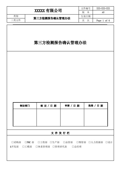
第三方检测报告(ICP)确认管理办法
测试元素
CAS NO
限值
镉(Cd)
7440-43-9
50ppm
六价铬(Cr6+)
18540-29-9
500ppm
铅(Pb)
7439-92-1
50ppm
汞(Hg)
7439-97-6
1000ppm
多溴联苯(PBB)
59536-65-1
1000ppm
多溴联苯醚(PBDE)
1163-19-5
5.5.3除特殊材料如硫化剂,无法提供干态样品时(因烘烤会使其挥发)可提供液态样品
5.6测试样品照片、样品名称的判定:
5.6.1测试报告上样品图片与供应商提交样品一致,样品名称与提交状态一致,
5.7测试方法的判定:
测试元素
CAS NO
测试方法
镉(Cd)
7440-43-9
IEC62321中说明或列出的方法/客户预先批准的其他检测方法
CTI(华测检测)报告有效性查询指引
SGS(通标国际)报告有效性查询指引
6.0相关文件
6.1《均质材质拆解作业规范》
7.0相关表单/记录
7.1《合作实验室名称及联系方式》
7.2《XX年供应商第三方测试报告有效期追踪》
8.0流程图
无
第三方检测报告确认管理办法
制定部门
制定/日期
审核/日期
批准/日期
文件发行栏
□采购部□PMC部□工程部□生产部□品管部□物管部□人力资源部□设计&开发部□工模部□体系管理部□管理者代表□总经理
修改履历
序号
章节
版次
制定或修改內容
日期
1
全部
为了确认及判读公司所有供应商来料及公司申请送测第三方机构出具的第三方检测报告的真
APC UPS 电池配置表
5小时
100AH 60块 A32型2个
6小时
100AH 70块 A20型4个
8小时
100AH 80块 A20型4个
APC SUVT系列UPS配置表
SUVT10KVA UPS配置表
SUVT15KVA UPS配置表
后备时间 UPS型号
电池配置 电池箱
后备时间 UPS型号
电池配置 电池箱
30分钟
17AH 32块 A8型1个 30分钟
2小时
100AH 8块 A8型1个
2.5小时 3小时
SU5000UXICH
100AH 8块 A8型1个 100AH 12块 A12型1个
4小时
100AH 16块 A16型1个
5小时
100AH 20块 A20型1个
6小时
100AH 20块 A20型1个
8小时
100AH 24块 A12型2个
APC SURT系列UPS配置表
5小时
100AH 32块 A16型2个
6小时
65AH 64块 A16型4个
8小时
100AH 64块 A16型4个
SURT1000VA UPS配置表
后备时间 UPS型号
电池配置
30分钟
12AH 4块
1小时
24AH 4块
1.5小时
38AH 4块
2小时
38AH 4块
2.5小时 3小时
SURT1000UXICH
8小时
100AH 6块
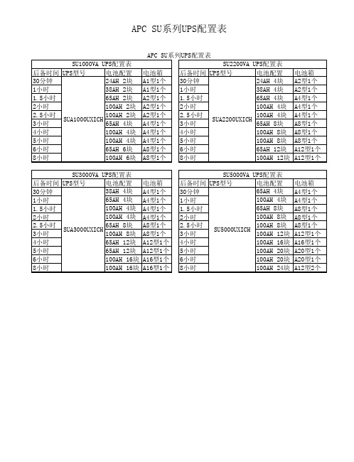
APC SU系列UPS配置表
SU2200VA UPS配置表
电池箱
后备时间 UPS型号
电池配置 电池箱
A1型1个 30分钟
24AH 4块 A2型1个
us锂电池运输标签要求

us锂电池运输标签要求英文回答:Lithium Battery Transportation Labeling Requirements.The transportation of lithium batteries is subject to a number of regulations, both domestic and international. These regulations are designed to ensure the safe transportation of lithium batteries and to prevent firesand explosions.In the United States, the Department of Transportation (DOT) regulates the transportation of lithium batteries.The DOT's regulations are contained in 49 CFR Parts 171-180.The DOT's regulations require that lithium batteries be labeled with the following information:The UN number for lithium batteries: UN 3480 or UN 3090。
The proper shipping name: Lithium batteries or Lithium batteries packed with equipment.The hazard class: Class 9。
The packing group: Group I, II, or III.The net weight of the lithium batteries in kilograms.The name of the shipper and the consignee.The address of the shipper and the consignee.The telephone number of the shipper and the consignee.The emergency response telephone number.The date of shipment.The total number of packages.In addition to the DOT's regulations, there are a number of other international regulations that apply to the transportation of lithium batteries. These regulations include the International Air Transport Association (IATA) Dangerous Goods Regulations and the International Maritime Dangerous Goods (IMDG) Code.The IATA Dangerous Goods Regulations and the IMDG Code contain similar requirements to the DOT's regulations. However, there are some minor differences between the regulations. For example, the IATA Dangerous Goods Regulations require that lithium batteries be labeled with a lithium battery mark. The IMDG Code does not require a lithium battery mark.It is important to be aware of the different regulations that apply to the transportation of lithium batteries. Failure to comply with these regulations can result in fines and other penalties.中文回答:美国锂电池运输标签要求。
A264B-SUR-S530-A3中文资料
元器件交易网EVERLIGHT ELECTRONICS CO.,LTD.DATA SHEETPART NO. DATE : : A264B/SUR/S530-A3 2005/8/26 CHR&D1DEPARTMENT : . REVISION :2RECEIVED■ MASS PRODUCTION □ PRELIMINARY □ CUSTOMER DESIGN DEVICE NUMBER : PAGE : 6CUSTOMER DESIGNERCDAE-026-077CHECKER APPROVERREV.DESCRIPTIONRELEASE DATEOFFICE: 7C BUILDING, LIAN HUA PORT INDUSTRIAL DISTRICT, LIAN HUA SHAN BONDED PRICESSING ZONE PAN YU, GUANG ZHU, CHINA TEL. : (020)84860913,84860914 FAX : (020)84860600 http : //元器件交易网EVERLIGHT ELECTRONICS CO.,LTD.Technical Data Sheet3.0mm Round Type LED Lamps A264B/SUR/S530-A3█ Features :● ● ●Low power consumption High efficiency and low cost Good control and free combinations on the colors of LED lamps Good lock and easy to assembly Stackable and easy to assembly Stackable vertically and easy to assembly Versatile mounting on P.C board or panel Stackable horizontally and easy to assembly Pb free The product itself will remain within RoHS compliant version.● ● ● ● ● ● ●█ Descriptions :● ●ARRAY=Plastic Holder+Combinations of Lamps The array will easily mount the applicable lamps on any panel up to█ Applications :●ed as indicators of indicating the Degree, Functions, Positions etc, in electronic instruments.PART NO. 264-10SURD/S530-A3Chip Material AlGaInP Emitted Color Hyper RedLens ColorRed DiffusedEVERLIGHT ELECTRONICS CO.,LTD. Device Number : CDAE-026-077http : // Prepared da 2005/8/26REV.:2Page: 1 of 6Prepared by:Lan Feng元器件交易网EVERLIGHT ELECTRONICS CO.,LTD.Technical Data Sheet 3.0mm Round Type LED LampsA264B/SUR/S530-A3Package DimensionsNotes: 1.All dimensions are in millimeters, tolerance is 0.25mm except being specified2.Lead spacing is measured where the lead emerge from the package█ Absolute Maximum Ratings at Ta = 25℃Parameter Forward Current Operating Temperature Storage Temperature Soldering Temperature Electrostatic Discharge Power Dissipation Peak Forward Current Reverse Voltage Symbol IF Topr Tstg Tsol ESD Pd IF(Peak) VR Rating Unit mA ℃ ℃ ℃ V mW mA V25-40 to +85 -40 to +100 260 ± 5 2000 60 60 5Note: *1:IFP Conditions --Pulse Width ≦ 1msec and Duty ≦ 1/10. *2:Soldering time ≦ 5 seconds.EVERLIGHT ELECTRONICS CO.,LTD. Device Number : CDAE-026-077http : // Prepared date: 2005/8/26REV.: Prepared by:2Page:2 0f 6Lan Feng元器件交易网EVERLIGHT ELECTRONICS CO.,LTD.Technical Data Sheet 3.0mm Round Type LED LampsA264B/SUR/S530-A3Electro-Optical Characteristics (Ta=25℃)Parameter Forward Voltage Reverse Current Luminous Intensity Viewing Angle Peak Wavelength Dominant Wavelength Spectrum Radiation Bandwidth Symbol VF IR Iv 2θ1/2 λp λd △λ Condition IF= VR= IF= IF= IF= IF= IF= 20 5 20 20 20 20 20 mA V mA mA mA mA mA Min. / / 63 / / / / Typ. 2.0 / 125 60 632 624 20 Max. 2.4 10 / / / / / Unit V μA mcd deg nm nm nmEVERLIGHT ELECTRONICS CO.,LTD. Device Number : CDAE-026-077http : // Prepared date: 2005/8/26REV.: Prepared by:2Page: 3 of 6Lan Feng元器件交易网EVERLIGHT ELECTRONICS CO.,LTD.Technical Data Sheet 3.0mm Round Type LED LampsA264B/SUR/S530-A3 Typical Electro-Optical Characteristic Curves:█EVERLIGHT ELECTRONICS CO.,LTD. Device Number : CDAE-026-077http : // Prepared date: 2005/8/26REV.:2Page: 4 of 6Prepared by: Lan Feng元器件交易网EVERLIGHT ELECTRONICS CO.,LTD.Technical Data Sheet 3.0mm Round Type LED LampsA264B/SUR/S530-A3█Reliability test items and conditions:Test Sample Ac/Re Hours/Cycle Size SEC 76 PCS 0/1NO 1Item Solder HeatTest Conditions TEMP : 260℃ ± 5 ℃ H : +100℃ 15min ∫ 5 min L : -40℃ 15min H : +100℃ 5min ∫ 10 sec L : -10℃ 5min TEMP : 100℃2Temperature Cycle300 CYCLES 76 PCS0/13Thermal Shock300 CYCLES 76 PCS0/14High Temperature Storage1000 HRS76 PCS0/15Low Temperature StorageTEMP : -40℃ TEMP : 25℃ IF = 20mA 85℃ / 85% RH1000 HRS76 PCS0/16 7DC Operating Life High Temperature / High Humidity1000 HRS 1000 HRS76 PCS 76 PCS0/1 0/1EVERLIGHT ELECTRONICS CO.,LTD.http : // Prepared date: 2005/8/26REV.:2Prepared by:Page: 5 of 6 Lan FengDevice Number :CDAE-026-077元器件交易网EVERLIGHT ELECTRONICS CO.,LTD.Technical Data Sheet 3.0mm Round Type LED LampsA264B/SUR/S530-A3Packing Quantity Specification1.500PCS/1Bag,4Bags/1Box 2. 10Boxes/1CartonLabel Form SpecificationCPN: Customer's Production Number P/N : Production Number QTY: Packing QuantityRoHSCAT: Ranks HUE: Peak Wavelength REF: Reference LOT No: Lot Number MADE IN TAIWAN: Production PlaceA264B/SUR/S530-A3Notes 1. Above specification may be changed without notice. EVERLIGHT will reserve authority on material change for above specification. 2. When using this product, please observe the absolute maximum ratings and the instructions for using outlined in these specification sheets. EVERLIGHT assumes no responsibility for any damage resulting from use of the product which does not comply with the absolute maximum ratings and the instructions included in these specification sheets. 3. These specification sheets include materials protected under copyright of EVERLIGHT corporation. Please don't reproduce or cause anyone to reproduce them without EVERLIGHT 'sconsent.EVERLIGHT ELECTRONICS CO., LTD. Office: No 25, Lane 76, Sec 3, Chung Yang Rd, Tucheng, Taipei 236, Taiwan, R.O.C Tel: (886-2-2267-2000, 2267-9936 Fax: 886-2267-6244, 2267-6189, 2267-6306 http:\\EVERLIGHT ELECTRONICS CO.,LTD.http : // Prepared date: 2005/8/26REV.: Prepared by:2Page: 6 0f 6 Lan FengDevice Number :CDAE-026-077。
有害物质HSF手机终端客户要求

正己烷 N-甲基吡咯烷酮 (NMP) 正丙基溴(nPB)
所有供应商制程中使 溶剂萃取,采用 GC-MS 或 HPLC-MS 法分析 5ppm最低检出限 用的清洗剂、去油剂
溶剂萃取,采用 GC-MS 或 HPLC-MS 法分析 5ppm最低检出限
采用EN14582法测定总溴、50ppm最低检出限(EN14582),终端客户公司预先批准的 其他检测方法
1000 ppm 且 Br < 900 ppm
多溴二苯醚 (PBDE)
1000 ppm 且 Br < 900 ppm
包装材料 所有材料 所有材料 所有材料
邻苯二甲酸酯 溴及其化合物
氯及其化合物
总含量 1000 ppm
所有材料
900 ppm 1500 ppm (Cl + Br)
所有材料
不使用:必须是无元素氯(ECF)、完全无氯 (TCF)或无氯处理(PCF)
不使用
所有材料 所有材料 所有材料 所有材料
所有材料 热敏纸
粗燃剂 纸制品、纸箱、货盘、皮革 绝缘体、填料 用于塑料、纺织品、皮革的染料或 着色剂
润滑剂中的抗氧化添加剂
热敏纸
双酚A
执行未聚合BPA的最低 检出浓度 所有材料
粘合剂、塑料、环氧树脂
1000ppm
所有其它材料、除非客户公司预先批准 粘合剂、塑料、环氧树脂
所有供应商制程中使用的清洗剂、去油剂、脱模剂
终端客户要求解析
✓ 合规性证明
客户要求提供经认证的实验室出具的测试报告,以证明均质材料中以下物质的合规性
物质
需要检测的材料:
检测方法
砷 (As)
玻璃
总酸消解,ICP-MS
金属和陶瓷
美高勤8542E和8546A EMI 测试接收器数据手册说明书

Frequency ReferenceAging <±1 x 10⁻⁷/year Settability <±1 x 10⁻⁸Temperature stability <±1 x 10–885422E/85462A9 kHz to 2.9 GHz (to 6.5 GHz*)Frequency Span AccuracyBands 1 and 2Band 3 and Bypass Span ≤10 MHz ±2% of span + 10 Hz ±4% of span Frequency Readout AccuracySpan > 10 MHz ±3% of span ±6% of span±(frequency readout x frequency reference error** +85422E/85462A 1% of span + 20% of IF bandwidth + span accuracy + 100 Hz)Span ≤10 MHz ±2% of span + 10 Hz Span > 10 MHz±3% of spanMarker Count AccuracyFrequency spans ≤10 MHz±(marker frequency x Counter Resolutionfrequency reference Frequency spans ≤10 MHz Selectable from 10 Hz to 100 kHz error** + counter Frequency spans > 10 MHz Selectable from 100 Hz to 100 kHzresolution + 100 Hz)Sweep TimeFrequency spans > 10 MHz±(marker frequency x Range20 ms to 100 sfrequency reference Sweep triggerfree run, single, line, video, externalerror** + counter resolution + 1 kHz)* For 8546A EMI receiver only** Frequency reference error = (aging rate x period of time since lastadjustment + initial achievable accuracy + temperature stability)SpecificationsAll specifications apply over 0 °C to +55 °C. The EMI receiver will meet its specifications after 2 hours of storage at a con-stant temperature, within the operating temperature range, 30minutes after the analyzer is turned on, and after CAL ALL has been run.1981Amplitude SpecificationsCharacteristic Noise Indication with CISPR Measurement Bands(0 dB attenuation, 50 Ωinput termination) Band A, 9 to 150 kHz (200 Hz BW)Peak Quasi-Peak AveragePreamp off 15 to –15 dBµV 6 to –25 dBµV 3 to –27 dBµVPreamp on 2 to –28 dBµV –7 to –29 dBµV–9 to –31 dBµVBand B, 150 kHz to 30 MHz (9 kHz BW)Preamp off –3 dBµV–11 dBµV–18 dBµVPreamp on–8 dBµV–15 dBµV–21 dBµVBand C, 30 MHz to 1 GHz (120 kHz BW)Preamp off 9 dBµV 2 dBµV–5 dBµVPreamp on 4 dBµV –2 dBµV –10 dBµVSystem Amplitude Accuracy Band 1Band 2Band 3*9 kHz to 50 MHz20 MHz to 2.9 GHz 1 to 6.5 GHzSpecification ±2 dB±2 dBCharacteristic±1 dB±1 dB±3 dBLinear to Log Scale Switching Uncertainty85422E/85462A±0.25 dB at reference levelDisplay Scale Fidelity85422E/85462ALog maximum cumulative(0 to –66 dB from reference level, 0 to –64 dB for Band 3 only)3 kHz to 3 MHz IF BW ±(0.3 dB + 0.01 x dB from reference level)≤1 kHz IF BW±(0.4 dB + 0.01 x dB from reference level)Log incremental accuracy±0.4 dB/4 dB(0 to –56 dB from reference level; 0 to –54 dB for Band 3 only )Linear scale ±3% of reference levelGain Compression(Specification is derived from measured distortion with a total power at the input mixer of –10 dBm.If the IF BW ≤300 Hz, this applies only if signal separation ≥4 kHz and the signal amplitude is ≤reference level + 10 dB.)Band 1Band 2Band 3*9 kHz to 50 MHz20 MHz to 2.9 GHz 1 to 6.5 GHz200 kHz ≤f0<10 MHz < 0.75 dB< 0.75 dB< 0.75 dBf0≥10 MHz < 0.5 dB < 0.5 dB < 0.5 dBCharacteristic 1 dB compression point8542E/8546A( f0 ≥10 MHz)Preamp off89 dBµV 89 dBµV102 dBµVPreamp on 77 dBµV 77 dBµV77 dBµV(9 kHz <f0 <10 MHz)Preamp off85 dBµVPreamp on 72 dBµV85422E/85462A( f0 >10 MHz)(No bands)Preamp off102 dBµVPreamp on 75 dBµV(9 kHz ≤f0 ≤10 MHz)Preamp off95 dBµVPreamp on 68 dBµVThird Order Intercept Point Band 1Band 2Band 3* Bypassf0> 200 kHz, signal separation >50 kHz9 kHz to20 MHz to 1 to9 kHz to 8542E/8546A50 MHz 2.9 GHz 6.5 GHz 2.9 GHz Preamp off 97 dBµV97 dBµV112 dBµV 112 dBµVPreamp on85 dBµV85 dBµV85 dBµV85 dBµV 85422E/85462A(No Bands)Preamp off 112 dBµVPreamp on 85 dBµV* For 8546A EMI receiver only3Second Harmonic Band 1Band 2Band 3*Intercept Point9 kHz to20 MHz to 1 to 8542E/8546A 50 MHz 2.9 GHz 6.5 GHz 100 kHz ≤f 0≤1.8 GHz, > 2.9 GHzPreamp off 122 dBµV 122 dBµV 134 dBµV Preamp on 110 dBµV 110 dBµV100 dBµV1.8 GHz < f 0 ≤2.9 GHzPreamp off 105 dBµV Preamp on 105 dBµV 85422E/85462A (No bands)f 0 > 200 kHzPreamp off 134 dBµV Preamp on 100 dBµVAmplitude Specifications (continued)Other Input Related Spurious –65 dBc (Band 1, Band 2, and Band 3*)Residual Responses (0 dB attenuation, 50 Ωinput termination, preamp on)8542E/8546A < 30 kHz < –2 dBµV > 30 kHz< –10 dBµV 85422E/85462A 9 to 150 kHz< +2 dBµV 150 kHz to 2.9 (or 6.5 GHz*)< –8 dBµV85422E/85462Af 0≤400 kHzf 0> 400 kHzPreamp off ≤–18 dBµV Preamp on≤–39 dBµV* For 8546A EMI receiver onlyIF and Display SpecificationsIF BandwidthsMeasurement (6 dB) 200 Hz, 9 kHz, 120 kHz(conforms to CISPR Publication 16) Bandwidth accuracy 1 MHz, 6 dB BW ±10%Diagnostic (3 dB) 30 Hz to 300 kHz in 1-3-10 steps(±20% characteristic), also 3 MHzand 5 MHz Demodulation AM and FMInputs and Outputs SpecificationsFront Panel Inputs8542E/8546ALow frequency Type-N female, 50 ΩnominalHigh frequency Type-N female, 50 Ωnominal85422E/85462A Type-N female, 50 Ωnominal Maximum Safe Input Level8542E/8546Adc voltage0 VAverage continuous power9 kHz to 2.9 GHz137 dBµV (30 dBm)1 GHz to 6.5 GHz*137 dBµV (30 dBm) with ≥10 dBinput attenuationPeak pulsed powerBand 1 ( 9 kHz to 50 MHz) 2 kW peak for 10 µs, > 20 dBinput attenuationBand 2 (20 MHz to 2.9 GHz)100 W peak for < 10 µs, <1% dutycycle and > 30 dB input attenuation 85422E/85462Adc voltage0 V (dc coupled), 50 V (ac coupled) Average continuous power9 kHz to 2.9 GHz137 dBµV (30 dBm)2.9 GHz to 6.5 GHz*137 dBµV (30 dBm) with 10 dBinput attenuationPeak pulsed power 50 dBm (100 W) for 10 µs pulsewidth and 1% duty (Preamp off)cycle, input attenuation ≥30 dB Input Attenuation8542E/8546AInput attenuator 0 to 50 dB in 10 dB stepsLinearity test attenuator 4 dB85422E/85462AInput attenuator 0 to 70 dB in 10 dB steps9 to 74 kHz fixed74 to 198 kHz fixed198 to 525 kHz fixed525 to 1025 kHz fixed1 to2 MHz fixed2 to 6 MHz tunable (20%3 dB bandwidth)6 to 17 MHz tunable (10% 3 dB bandwidth)17 to 29 MHz tunable (7% 3 dB bandwidth)29 to 52 MHz tunable (8% 3 dB bandwidth)52 to 98 MHz tunable (6% 3 dB bandwidth)98 to 152 MHz tunable (6% 3 dB bandwidth)152 to 216 MHz tunable (6% 3 dB bandwidth)216 to 330 MHz tunable (5% 3 dB bandwidth)330 to 500 MHz tunable (5% 3 dB bandwidth)0.5 to 1 GHz tunable (4% 3 dB bandwidth)1 to 2.9 GHz fixed2.9 to 6.5 GHz*fixed Averaging Bandwidths30 Hz to 1 MHz in 1-3-10 steps(±30% characteristic) and 3 MHz.Post-detection single polelow-pass filters. 1, 3 and 10 Hzdigital filters with anti-aliasing DetectorsMeasurement Peak, Quasi-Peak and AverageQuasi-Peak time constantsconform with CISPR Publication 16 Overload8542E/8546A Broadband RF (Bands1 and2 only) and IF85422E/85462A IFPreamplification8542E/8546ABands 1 and 2 12 dBBand 3* and BYPASS 27 dB ±4 dB85422E/85462A27 dB ±1.5 dB ≤500 MHz,±4 dB > 500 MHzInput VSWR0 dB input attenuation≤1.0 GHz 2 : 11.0 GHz < f0≤2.9 GHz 2.5 : 110 dB input attenuation≤1.2 GHz 1.2 : 11.2 GHz< f0≤1.7 GHz 1.3 : 11.7 GHz< f0≤2.9 GHz 1.6 : 1Front Panel OutputsTracking generator Type-N female, 50 Ωnominal85422E/85462A onlyProbe power +15 Vdc ±7% at 150 mA max–12.6 Vdc ±10% at 150 mA max Earphone jack1/8 in monoaural jackCalibrator signal Type-N female, 50 Ωnominal,300 MHz, –20 dBm ±0.4 dB External ALC negative detectorRear Panel Inputs and Outputs10 MHz REF OUTPUT BNC female, 50 ΩOutput amplitude> 0 dBmEXT REF IN BNC femaleFrequency 10MHzInput amplitude range -2 to 10 dBm* For 8546A EMI receiver onlyInput Filter Bandwidths(all 3 dB bandwidths are characteristics) 4Inputs and Outputs Specifications (continued)AUX IF OUTBNC female, 50 ΩFrequency21.4 MHzAmplitude range –10 to –60 dBm AUX VIDEO OUT BNC femaleAmplitude range 0 to 1 V (uncorrected)EXT KEYBOARDInterface compatible with HP C1405A Option ABA keyboard and most IBM/AT non auto-switching keyboards EXT TRIG INPUT BNC femaleTrigger levelPositive edge initiates sweep in EXT TRIG mode (TTL)LO OUTPUTSMA female, 50 ΩFrequency range 3.0 to 6.8214 GHz HI-SWEEP IN/OUT 85422E/85462ASMA female, Outputhigh=sweep,low=retrace (TTL)Input open collector, low stops sweep 85420E/85460ASMA female Outputhigh=sweep,low=retrace (TTL)Tracking Generator SpecificationsOutput Frequency Range 9 kHz to 2.9 GHz Output Power LevelRange –1 to –66 dBm Resolution 0.1 dB VernierRange 9 dB Accuracy (25 °±10 °C)(–20 dBm at 300 MHz, 16 dB attenuation)±0.2 dB / dB Incremental cumulative ±0.5 dB total Output attenuator range 0 to 56 dB in 8 dB steps Output Power SweepRangeResolution 0.1 dBGeneral SpecificationsEMI CompatibilityMeasurement characteristics are in compliance with CISPR Publication 16-1. IF has 6 dB meas-urement bandwidths of use above or below 1 GHz. Receiver is compliant with CISPR 11/1990,Group 1, Class B and EN 50082-1/1992Storage Media Internal 3.5-inch disk drive. 1.44 MByte DOS and LIF format Temperature RangeOperating0 to 55 °C Storage Media 5 to 45 °C Storage–20 to 65 °C Power RequirementsVoltagePower Consumption 8542E/8546A90 to 132 V rms’47 to 440 Hz On<615 VA; <265 W 198 to 264 V rms’47 to 66 Hz Off<5 WReceiver RF section 90 to 132 V rms’47 to 440 Hz On<500 VA; <180 W 198 to 264 V rms’47 to 66 Hz Off<5 WRF filter section90 to 132 V rms’47 to 440 Hz On<115 VA; <85 W 198 to 264 V rms’47 to 66 HzOff=0 WSWEEP INPUT/OUTPUT 85422E/85462A SMA female Output0 to 10 V ramp 85420E/85460A SMA female Input0 to 10 VREMOTE INTERFACE 85422E/85462A GPIB Option 023RS-23285420E/85460AGPIB compatible service port (for use by qualified repairpersonnel only)MONITOR OUTPUTR,G, B (composite video on G)25 kHz horizontal rate 60 Hz vertical rate AUX INTERFACE85422E/85462A only9-pin subminiature “D”5(–10 to –1 dBm)-(source attenuator setting)Related Literature Pub. Number Agilent 85875A Commercial Conducted EMIMeasurement Software 5964-1968E Agilent 85876A Commercial Radiated EMIMeasurement Software 5962-9450E Agilent 85878A EMI Report Generator 5965-6473E Agilent 85869PC EMI Measurement Software 5965-2885E Agilent Technologies’ Test and MeasurementSupport, Services, and AssistanceAgilent Technologies aims to maximize the value you receive, while minimizing your risk and problems. We strive to ensure that you get the test and measurement capabilities you paidfor and obtain the support you need. Our extensive support resources and services can help you choose the right Agilent products for your applications and apply them successfully. Every instrument and system we sell has a global warranty. Support is available for at least five years beyond the produc-tion life of the product. Two concepts underlie Agilent’s overall support policy: “Our Promise” and “Your Advantage.”Our Promise“Our Promise” means your Agilent test and measurement equip-ment will meet its advertised performance and functionality. When you are choosing new equipment, we will help you with product information, including realistic performance specifica-tions and practical recommendations from experienced test engineers. When you use Agilent equipment, we can verify that it works properly, help with product operation, and provide basic measurement assistance for the use of specified capabili-ties, at no extra cost upon request. Many self-help tools are available.Your Advantage“Your Advantage” means that Agilent offers a wide range of additional expert test and measurement services, which you can purchase according to your unique technical and business needs. Solve problems efficiently and gain a competitive edge by contracting with us for calibration,extra-cost upgrades, out-of-warranty repairs, and on-site education and training, as well as design, system integration, project management, and other professional services. Experienced Agilent engineers and tech-nicians worldwide can help you maximize your productivity, optimize the return on investment of your Agilent instruments and systems, and obtain dependable measurement accuracyfor the life of those products.Get assistance with all your test and measurement needs at: /find/assistProduct specifications and descriptions in thisdocument subject to change without notice.Copyright © 1997, 2000 Agilent TechnologiesPrinted in U.S.A. 5/005965-7096E。
离子色谱法

电化学检测器测定的组分
电导检测器 无机阴离子 无机阳离子 羧酸 磺酸 膦酸 胺,1o,2o,3o,4o 直流安培检测器 儿茶酚胺 苯酚 芳香胺 硫醇 氰化物 硫化物 碘化物 亚硫酸盐 积分安培检测器 碳水化合物 脂肪胺,1o,2o,3o 氨基酸 醇类 醛类 S类,除S(Ⅵ)
检测方式
吸收光谱法 发射光谱法(常用荧光法)
l
分析阴离子时,以Na2CO3/NaHCO3 或NaOH稀溶 液为洗脱液,分离柱为低交换容量的阴离子交 换树脂,抑制柱为高交换容量的阳离子交换树 脂。
分离柱中: 交换反应 R-OH
-
+ NaX
R-X- +NaOH R-OH
-
洗脱反应 R-X- +NaOH 抑制柱中:对洗脱液的反应 R-H++NaOH
样品基体 海水,河口水 海水,河口水 饮用水、地下水、工业废水 饮用水、地下水工业废水及 纯净水、地表水、生活废水 雨水、露水、雪水、冰雹、 冻雨 雨水、露水、雪水、冰雹、 冻雨 水溶液 饮用水、地下水、工业废水 氧瓶燃烧的固体样品及水样 空气样品 空气样品 空气样品 空气样品 空气样品 空气样品 空气样品 空气样品 空气样品 空气样品 空气样品
阳离子交换
电导、安培
阳离子交换, 离子对
电导、紫外, 安培
IC的应用
无机离子 可离解的有机化合物
国际现行的离子色谱标准分析方法(环境与高纯水分析)
方法编号① 200.10(a) 200.13(a) 218.6(a) 300.0(a) 300.1(a) 300.6(a) 300.7(a) 6060(a) 7199(a) 9056(a) EPA Method 7A 1994,p626 EPA Method 7A 1944,p637 5173(b) 2008(b) 3509(b) 5022(b) 6004(b) 6005(b) 6011(b) 6701(b) 7604(b) 方法名称 在线螯合预富集感应等离子 体 - 质谱测定海水中的痕量 元素 螯合预富集石墨炉原子吸收 测定对象 Cd、Co、Cu、U、V、Ni Cd、Co、Cu、Pb、Ni Cr(Ⅵ) NO3-、NO2-、SO42-、F-、Cl-、 ClO2- 、 ClO3- 、 Br- 、 BrO3- 、 3PO NO4 -、Cl-、PO 3-、SO 23 4 4
EPA 9056A 离子色谱法检测无机阴离子
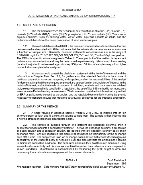
9056A - 1Draft Revision 1September 1999Pre-release version -- This method has NOT been released by OSW as part of Update IV.METHOD 9056A DETERMINATION OF INORGANIC ANIONS BY ION CHROMATOGRAPHY1.0SCOPE AND APPLICATION1.1This method addresses the sequential determination of chloride (Cl G ), fluoride (F G ),bromide (Br G ), nitrate (NO 3G ), nitrite (NO 2G ), phosphate (PO 43G ), and sulfate (SO 42G ) anions in aqueous samples, such as drinking water, waste water, aqueous extracts of solids, and the collection solutions from the bomb combustion of solid waste samples.1.2The method detection limit (MDL), the minimum concentration of a substance that can be measured and reported with 99% confidence that the value is above zero, varies for anions as a function of sample size. Generally, minimum detectable concentrations are in the range of 0.002-0.02 mg/L for F G , Br G , Cl G , NO 3G -N, NO 2G -N, PO 43G -P, and SO 42G with a 50-µL sample loop.The MDLs for specific anions are given in Table 1. The upper limit of the method is dependent on total anion concentration and may be determined experimentally. Maximum column loading (total anions) should not exceed approximately 500 ppm. Dilution of samples may allow higher concentration samples to be analyzed.1.3 Analysts should consult the disclaimer statement at the front of the manual and the information in Chapter Two, Sec.2.1, for guidance on the intended flexibility in the choice of methods, apparatus, materials, reagents, and supplies, and on the responsibilities of the analyst for demonstrating that the techniques employed are appropriate for the analytes of interest, in the matrix of interest, and at the levels of concern. In addition, analysts and data users are advised that, except where explicitly specified in a regulation, the use of SW-846 method is not mandatory in response to Federal testing requirements. The information contained in this method is provided by EPA as guidance to be used by the analyst and the regulated community in making judgments necessary to generate results that meet the data quality objectives for the intended application.2.0SUMMARY OF THE METHOD2.1 A small volume of aqueous sample, typically 2 to 3 mL, is injected into an ion chromatograph to flush and fill a constant volume sample loop. The sample is then injected into a flowing stream of carbonate-bicarbonate eluent.2.2The sample is pumped through two different ion exchange columns, then a suppressor device and into a conductivity detector. The two ion exchange columns, a precolumn or guard column and a separator column, are packed with low-capacity, strongly basic anion exchange resin. Ions are separated into discrete bands based on their affinity for the exchange sites of the resin. The suppressor is an ion exchange-based device that reduces the background conductivity of the eluent to a low or negligible level and also converts the anions in the sample to their more conductive acid form. The separated anions in their acid form are measured using an electrical-conductivity cell. Anions are identified based on their retention times compared to known standards. Quantitation is accomplished by measuring the peak height or area and comparing it to a calibration curve generated from known standards.3.0DEFINITIONSRefer to Chapter One and Chapter Three for applicable definitions.4.0INTERFERENCES4.1Any species with a retention time similar to that of the desired ion will interfere. Large quantities of ions eluting close to the ion of interest will also result in an interference. Separation can be improved by adjusting the eluent concentration and/or flow rate. Sample dilution and/or the use of the method of standard additions can also be used. For example, high levels of organic acids that may interfere with inorganic anion analysis may be present in industrial wastes. Two common species, formate and acetate, elute between fluoride and chloride.4.2The water dip or negative peak that elutes near, and can interfere with, the fluoride peak can usually be eliminated by the addition of the equivalent of 1 mL of concentrated eluent (100 times more concentrated than the solution described in Section 7.3) to 100 mL of each standard and sample.4.3Method interferences may be caused by contaminants in the reagent water, reagents, glassware, and other sample processing apparatus that lead to discrete artifacts or elevated baseline in ion chromatograms.4.4Samples that contain particles larger than 0.45 µm and reagent solutions that contain particles larger than 0.20 µm require filtration to prevent damage to instrument columns and flow systems. The associated method blanks must also be filtered if any samples or reagents have undergone filtration.4.5The acetate, formate, and other monovalent organic acids anion elutes early in the chromatographic run and can interfere with fluoride. The retention times of anions may differ when large amounts of acetate are present. Therefore, this method is not recommended for leachates of solid samples where acetate is used for pH adjustment.5.0SAFETY5.1The toxicity or carcinogenicity of each reagent used in this method has not been fully established. Each chemical should be regarded as a potential health hazard and exposure should be as low as reasonably achievable. Cautions are included for known extremely hazardous materials or procedures.5.2Each laboratory is responsible for maintaining a current awareness file of OSHA regulations regarding the safe handling of the chemicals specified in this method. A reference file of Material Safety Data Sheets (MSDS) should be made available to all personnel involved in the chemical analysis. The preparation of a formal safety plan is also advisable.9056A - 2Draft Revision 1September 1999 Pre-release version -- This method has NOT been released by OSW as part of Update IV.9056A - 3Draft Revision 1September 1999Pre-release version -- This method has NOT been released by OSW as part of Update IV.6.0EQUIPMENT AND SUPPLIES6.1Ion chromatograph, capable of delivering 1 to 5 mL of eluent per minute at a pressure of 1000 to 4000 psi (6.5 to 27.5 MPa). The chromatograph shall be equipped with an injection valve, a 25- to 100-µL sample loop, and set up with the following components, as schematically illustrated in Figure 1.6.1.1Precolumn, a guard column placed before the separator column to protectthe separator column from being fouled by particulates or certain organic constituents (4 x 50 mm, Dionex IonPac AG4A -SC P/N 43175, or equivalent).6.1.2Separator column (see Figure 2), a column packed with low-capacitypellicular anion exchange resin that is styrene divinylbenzene-based has been found to be suitable for resolving F G , Br G , Cl G , NO 3G , NO 2G , PO 43G , and SO 42G (4 x 250 mm, Dionex IonPac AS4A-SC P/N 43174, or equivalent).6.1.3Suppressor, an ion exchange-based device that is capable of converting theeluent and separated anions to their respective acid forms (Dionex AMMS-II P/N 43074 or ASRS Ultra P/N 53946, or equivalent).6.1.4Detector, a low-volume, flow-through, temperature-compensated, electricalconductivity cell (approximately 1.25-µL volume, Dionex CD20, or equivalent) equipped with a meter capable of reading from 0 to 1,000 Siemens/cm on a linear scale.6.1.5Pump, capable of delivering a constant flow of approximately 1 to 5 mL/minthroughout the test and tolerating a pressure of 1000 to 4000 psi (6.5 to 27.5 MPa).6.2Syringe, minimum capacity of 1 mL, equipped with a male pressure fitting.6.3Appropriate chromatographic data and control software to acquire data. Dionex PeakNet was used to record and process the chromatogram shown in Figure 2. Alternatively, an integrator or recorder can be used to integrate the area under the chromatographic peaks. If an integrator is used, the maximum area measurement must be within the linear range of the integrator. The recorder should be compatible with the detector output with a full-scale response time of 2 seconds or less. Systems using an integrator or recorder may not necessarily achieve the same MDLs shown in Table 1.6.4Analytical balance, capable of weighing to the nearest 0.0001 g.6.5Pipets, Class A volumetric flasks, beakers: assorted sizes.7.0REAGENTS AND STANDARDS7.1Reagent grade chemicals shall be used in all tests. Unless otherwise indicated, it is intended that all reagents shall conform to the specifications of the Committee on Analytical Reagents of the American Chemical Society, where such specifications are available. Other9056A - 4Draft Revision 1September 1999Pre-release version -- This method has NOT been released by OSW as part of Update IV.grades may be used, provided it is first ascertained that the reagent is of sufficiently high purity to permit its use without lessening the accuracy of the determination.7.2Reagent water. All references to water in this method refer to reagent water, as defined in Chapter One.7.3Eluent, 1.7 mM NaHCO 3/1.8 mM Na 2CO 3. Dissolve 0.2856 g of sodium bicarbonate (1.7 mM NaHCO 3) and 0.3816 g of sodium carbonate (1.8 mM Na 2CO 3) in reagent water and dilute to 2 L with reagent water or follow manufacturer’s guidance for the proper eluent for each specific column.7.4Suppressor regenerant solution (25 mM H 2SO 4), if required. Add 2.8 mL of concentrated sulfuric acid (H 2SO 4) to 4 L of reagent water.7.5Stock solutions (1,000 mg/L). Certified standards may also be purchased and used as stock solutions.7.5.1Bromide stock solution (1.00 mL = 1.00 mg Br G ). Dry approximately 2 g ofsodium bromide (NaBr) for 6 hours at 150°C, and cool in a desiccator. Dissolve 1.2877 g of the dried salt in reagent water, and dilute to 1 L with reagent water in a Class A volumetric flask.7.5.2Chloride stock solution (1.00 mL = 1.00 mg Cl G ). Dry sodium chloride (NaCl)for 1 hour at 600°C, and cool in a desiccator. Dissolve 1.6484 g of the dry salt in reagent water, and dilute to 1 L with reagent water in a Class A volumetric flask.7.5.3Fluoride stock solution (1.00 mL = 1.00 mg F G ). Dissolve 2.2100 g ofsodium fluoride (NaF) in reagent water, and dilute to 1 L with reagent water in a Class A volumetric flask. Store in a chemical-resistant glass or polyethylene container.7.5.4Nitrate stock solution (1.00 mL = 1.00 mg NO 3G ). Dry approximately 2 g ofsodium nitrate (NaNO 3) at 105°C for 24 hours. Dissolve exactly 1.3707 g of the dried salt in reagent water, and dilute to 1 L with reagent water in a Class A volumetric flask.7.5.5Nitrite stock solution (1.00 mL = 1.00 mg NO 2G ). Place approximately 2 gof sodium nitrate (NaNO 2) in a 125 mL beaker and dry to constant weight (about 24 hours)in a desiccator containing concentrated H 2SO 4. Dissolve 1.4998 g of the dried salt in reagent water, and dilute to 1 L with reagent water in a Class A volumetric flask. Store in a sterilized glass bottle. Refrigerate and prepare monthly.NOTE: Nitrite is easily oxidized, especially in the presence of moisture, and only freshreagents are to be used.NOTE:Prepare sterile bottles for storing nitrite solutions by heating for 1 hour at 170°C inan air oven.9056A - 5Draft Revision 1September 1999Pre-release version -- This method has NOT been released by OSW as part of Update IV.7.5.6Phosphate stock solution (1.00 mL = 1.00 mg PO 43G ). Dissolve 1.4330 gof potassium dihydrogen phosphate (KH 2PO 4) in reagent water, and dilute to 1 L with reagent water in a Class A volumetric flask.7.5.7Sulfate stock solution (1.00 mL = 1.00 mg SO 42G ). Dissolve 1.4790 g of thedried salt in reagent water, and dilute to 1 L with reagent water in a Class A volumetric flask.7.6Anion working solutionsPrepare a blank and at least three different working solutions containing the following combinations of anions. The combination anion solutions must be prepared in Class A volumetric flasks. See Table 2.7.6.1Prepare the high-range standard solution by combining the volumes of eachanion stock solution specified in Table 2 in a Class A volumetric flask and diluting the mixture to 1 L with reagent water.7.6.2Prepare the intermediate-range standard solution by diluting 10.0 mL of thehigh-range standard solution (see Table 2) to 100 mL with reagent water.7.6.3Prepare the low-range standard solution by diluting 20.0 mL of theintermediate-range standard solution (see Table 2) to 100 mL with reagent water.7.7Stability of standardsStock solutions are stable for at least 1 month when stored at 4 ± 2E C. Dilute working standards should be prepared weekly, except those that contain nitrite and phosphate, which should be prepared fresh daily. The validity of standards can be confirmed through the analysis of a freshly prepared ICV (Sec. 9.4).8.0SAMPLE COLLECTION, PRESERVATION, AND STORAGE8.1All samples must be collected using a sampling plan that addresses the considerations discussed in Chapter Nine of this manual.8.2Samples should be analyzed within 48 hours of collection. Preserve by refrigeration at 4 ± 2E C.9.0QUALITY CONTROL9.1All quality control data should be maintained and available for easy reference and inspection. Refer to Chapter One for additional quality control guidelines.9.2For each batch of samples processed, method blanks must be carried throughout the entire sample preparation and analytical process according to the frequency described in Chapter One. If the samples are filtered, the associated method blanks must also be filtered.These blanks will be useful in determining if samples were contaminated during sample preparation or handling. Refer to Chapter One for the proper protocol when analyzing blanks.9.3 For each batch of samples processed, at least one laboratory control sample must be carried throughout the entire sample preparation and analytical process as described in Chapter One. The laboratory control samples should be spiked with each analyte of interest at the project-specific action level or when lacking project-specific action levels, between the low and midlevel standards. Acceptance criteria should be set at a laboratory-derived limit developed through the use of historical analyses. In the absence of historical data, this limit should be set at ± 20% of the spiked value. In the presence of historical data, ± 20% must still be the limit of maximum deviation to determine acceptability. If the laboratory control sample cannot be considered acceptable, the laboratory control sample must be re-run once, and if still unacceptable, then all samples after the last acceptable laboratory control sample must be reprepped and reanalyzed. Refer to Chapter One for more information.9.4After initial calibration, the calibration curve must be verified by use of an initial calibration verification (ICV) standard. The ICV standard must be prepared from an independent (second source) material at or near the mid-range of the calibration curve. The acceptance criteria for the ICV standard must be no greater than ± 10% of its true value. If the calibration curve cannot be verified within the specified limits, the cause must be determined and the instrument recalibrated before samples are analyzed. The analysis data for the ICV must be kept on file with the sample analysis data.9.5The calibration curve must be verified at the end of each analysis batch and/or after every 10 samples by use of a calibration blank and a continuing calibration verification (CCV) standard. The CCV should be made from the same material as the initial calibration standards at or near mid-range. The acceptance criteria for the CCV standard must be ± 10% of its true value and the calibration blank must not contain target analytes above 2-3 times the MDL for the curve to be considered valid. If the calibration cannot be verified within the specified limits, the sample analysis must be discontinued, the cause determined and the instrument recalibrated. All samples following the last acceptable CCV/calibration blank must be reanalyzed. The analysis data for the CCV/calibration blank must be kept on file with the sample analysis data.9.6Method detection limit (MDL)MDLs should be established for all analytes using reagent water (blank) fortified at a concentration of approximately 3 times the estimated instrument detection limit. To determine MDLs, take seven replicate aliquots of the fortified reagent water and process through the entire analytical method. Perform all calculations defined in the method and report concentration values in the appropriate units.9.7Matrix spike/matrix spike duplicates (MS/MSDs)MS/MSDs are intralaboratory split samples spiked with identical concentrations of target analytes. The spiking occurs prior to sample preparation and analysis. An MS/MSD pair is used to document the bias and precision of a method in a given sample matrix. MS/MSDs are to be analyzed at the frequency of one per analytical batch as described in Chapter One. Refer to the definitions of bias and precision in Chapter One for the proper data reduction protocols. Each9056A - 6Draft Revision 1September 1999 Pre-release version -- This method has NOT been released by OSW as part of Update IV.laboratory should calculate its own acceptance criteria based on its historical data for each matrix type. Refer to Chapter One for guidance.10.0CALIBRATION AND STANDARDIZATION10.1Establish ion chromatographic operating parameters equivalent to those indicated in Table 1, or as recommended by the manufacturer.10.2For each analyte of interest, prepare calibration standards at a minimum of three concentrations and a blank by adding accurately measured volumes of one or more stock standards to a Class A volumetric flask and diluting to volume with reagent water. If the working range exceeds the linear range of the system, a sufficient number of standards must be analyzed to allow an accurate calibration curve to be established. One of the standards should be representative of a concentration near, but above, the method detection limit if the system is operated on an applicable attenuator range. The other standards should correspond to the range of concentrations expected in the sample or should define the working range of the detector. Unless the attenuator range settings are proven to be linear, each setting must be calibrated individually. The calibration curve should be prepared every 12 hours of operation.10.3Using a fixed injection volume of between 25 to 100 mL (determined by injection loop volume) of each calibration standard, tabulate peak area (preferably) or height responses against the concentration. The results are used to prepare a calibration curve for each analyte. During this procedure, retention times must be recorded.10.4The working calibration curve must be verified on each working day, or whenever the anion eluent strength is changed, and for every batch of samples, by injection of a CCV standard (Sec. 9.5). If the response or retention time for any analyte varies from the expected (i.e., previous) values by more than ± 10%, the test must be repeated, using fresh calibration standards. If the results are still more than ± 10%, an entirely new calibration curve must be prepared for that analyte.10.5Nonlinear response can result when the separator column capacity is exceeded (overloading). Maximum column loading (total anions) should not exceed approximately 500 ppm.11.0PROCEDURE11.1Sample preparationWhen aqueous samples are injected, the water passes rapidly through the columns, and a negative "water dip" is observed that may interfere with the early-eluting fluoride and/or chloride ions. The water dip should not be observed in combustate samples since the collecting solution is a concentrated eluent solution that will be equivalent to the eluent strength when diluted to 100-mL with reagent water according to the bomb combustion procedure. Any dilutions required in analyzing other water samples should be made with the eluent solution. The water dip, if present, may be removed by adding concentrated eluent to all samples and standards to result in a final sample/standard solution that is equivalent to bicarbonate/carbonate concentration of the eluent.9056A - 7Draft Revision 1September 1999 Pre-release version -- This method has NOT been released by OSW as part of Update IV.9056A - 8Draft Revision 1September 1999Pre-release version -- This method has NOT been released by OSW as part of Update IV.When a manual system is used, it is necessary to micropipet concentrated buffer into each sample. The recommended procedures follow:11.1.1Prepare a 100-mL stock of eluent 100 times normal concentration bydissolving 1.428 g NaHCO 3 and 1.908 g Na 2CO 3 in 100-mL reagent water or use the manufacturer’s specified eluent. Cover or seal the volumetric flask .11.1.2Pipet 5 mL of each sample into a clean polystyrene micro-beaker.Micropipet 50 mL of the concentrated buffer into the beaker and stir well.11.1.3Dilute the samples with eluent, if necessary, to concentrations within thelinear range of the calibration.11.2Sample analysis11.2.1Start the flow of regenerant through the suppressor device, if required.Alternatively, apply the appropriate current to the ASRS immediately after starting the eluent pump.11.2.2Set up the recorder range for maximum sensitivity and any additional rangesneeded.11.2.3Begin to pump the eluent through the columns. After a stable baseline isobtained (approximately 30 minutes), inject a midrange standard. If the peak area or height deviates by more than ± 10% from that of the previous run, prepare fresh standards.11.2.4Begin to inject standards starting with the lowest concentration standard andincreasing in concentration. Calculate the regression parameters for the initial standard curve. Compare these values with those obtained in the past. If they exceed the control limits, stop the analysis and identify and correct the problem.11.2.5Inject an ICV standard. Calculate the concentration from the calibrationcurve and compare the known value. If the ± 10% control limits are exceeded, stop the analysis until the problem is found. Recalibration is necessary.11.2.6When an acceptable value has been obtained for the ICV standard, beginto inject the samples.11.2.7Load and inject a fixed amount of well-mixed sample. Flush the injectionloop thoroughly (with at least 5x the loop volume), using each new sample. Use the same size loop for all standards and samples. Record the resulting peak size in area or peak height units. An automated constant volume injection system may also be used.11.2.8The width of the retention time window used to make identifications shouldbe based on measurements of actual retention time variations of standards over the course of a day. Three times the standard deviation of a retention time may be used to calculate a suggested window size for a compound. However, the experience of the analyst should weigh heavily in the interpretation of chromatograms.9056A - 9Draft Revision 1September 1999Pre-release version -- This method has NOT been released by OSW as part of Update IV.y i 'mx i %bx j '(y j &b)m11.2.9If the response for the peak exceeds the working range of the system, dilutethe sample with an appropriate amount of reagent water or eluent and reanalyze.11.2.10If the resulting chromatogram fails to produce adequate resolution, or ifidentification of specific anions is questionable, spike the sample with an appropriate amount of standard and reanalyze.12.0DATA ANALYSIS AND CALCULATIONS12.1Prepare separate calibration curves for each anion of interest by plotting the peak areas or peak heights of the standards against the concentration values. Compute the concentration of each analyte in the sample by comparing the sample peak response with the standard curve. Appropriate chromatography data analysis software may be used to perform the functions listed in 12.3 and 12.4.12.2Many systems will automatically calculate the sample results, but if your system does not, then the enter the calibration standard concentrations and peak heights from the integrator or recorder into a calculator with linear least squares capabilities.12.3Calculate the slope (m) and the intercept (b). The slope and intercept define a relationship between the concentration and instrument response of the form:where:y i =predicted instrument response m=response slope x i =concentration of standard i b =interceptRearrangement of the equation above yields the concentration that corresponds to an instrument response:where:x j =calculated concentration for a sample y j =actual instrument response for a sample and m and b are the calculated slope and intercept from the calibration equation.12.4Enter the sample peak area or height into the calculator, and calculate the sample concentration in milligrams per liter.13.0METHOD PERFORMANCE13.1Examples of single-operator accuracy and precision values for reagent, drinking, and surface water, and mixed domestic and industrial wastewater are listed in Table 3. See EPA Method 300.0 for examples of multiple laboratory determinations of bias for the analytes using an IonPac AS4A column, bicarbonate/carbonate eluent, AMMS suppressor and conductivity detection (see Reference 1).13.2Combustate samplesTables 4 and 5 are based on 41 data points obtained by six laboratories who each analyzed four used crankcase oils and three fuel oil blends with crankcase in duplicate. The oil samples were combusted using Method 5050. A data point represents one duplicate analysis of a sample. One data point was judged to be an outlier and was not included in the results.14.0POLLUTION PREVENTION14.1Pollution prevention encompasses any technique that reduces or eliminates the quantity and/or toxicity of waste at the point of generation. Numerous opportunities for pollution prevention exist in laboratory operation. The EPA has established a preferred hierarchy of environmental management techniques that places pollution prevention as the management option of first choice. Whenever feasible, laboratory personnel should use pollution prevention techniques to address their waste generation. When wastes cannot be feasiblely reduced at the source, the Agency recommends recycling as the next best option.14.2The quantity of the chemicals purchased should be based on expected usage during its shelf life and disposal cost of unused material. Actual reagent preparation volumes should reflect anticipated usage and reagent stability.14.3For information about pollution prevention that may be applicable to laboratories and research institutions consult Less is Better: Laboratory Chemical management for Waste Reduction available from the American Chemical Society, 1155 16th Street, NW, Washington D.C. 20036, (202) 872-4477.15.0WASTE MANAGEMENTThe Environmental Protection Agency requires that laboratory waste management practices be conducted consistent with all applicable rules and regulations. The Agency urges laboratories to protect the air, water, and land by minimizing and controlling all releases from hoods and bench operations, complying with the letter and spirit of any sewer discharge permits and regulations, and by complying with all solid and hazardous waste regulations, particularly the hazardous waste identification rules and land disposal restrictions. For further information on waste management, consult The Waste Management Manual for Laboratory Personnel available from the American Chemical Society.9056A - 10Draft Revision 1September 1999 Pre-release version -- This method has NOT been released by OSW as part of Update IV.。
MX555ABA50M0000 超低阶噪声 50MHz LVPECL XO 时钟芯片说明书

MX555ABA50M0000 Ultra-Low Jitter 50MHz LVPECL XO ClockWorks® FUSIONGeneral DescriptionThe MX555ABA50M0000 is an ultra-low phase jitter XO with LVPECL output optimized for high line rate applications.Features• 50MHz LVPECL• Typical phase noise:- 101fs (Integration range: 1.875MHz-20MHz)• ±50ppm total frequency stability• -40°C to +85°C temperature range• Industry standard 6-Pin 5mm x 3.2mm LGA packageAbsolute Maximum Ratings¹Supply Voltage (VIN)..................................................+4.6V Lead Temperature (soldering, 10s)..............................260°C Case Temperature........................................................115°C Storage Temperature (T )............................-65°C to +125°CSESD Machine Model (200V)ESD Rating (HBM).........................................................2kV Operating Ratings²Supply Voltage (VIN).......................+2.375V to +3.63V Ambient Temperature (TA)....................-40°C to +85°C Junction Thermal ResistanceLGA (T ) Still Air.....................................58°C/W JCElectrical CharacteristicsVDD = 2.375 - 3.63V, TA = -40°C to +85°C, outputs terminated with 50 Ohms to VDD - 2V.³Symbol Parameter Condition Min.Typ.Max.Units IDD Supply Current120mA F0Center Frequency50MHz Frequency Stability Note 4±50ppmØj Phase Noise Integration Range (12kHz to 20MHz)Integration Range (1.875MHz to 20MHz)142101200-fsRMSTstart Start-Up Time20ms TR/TF Rise/Fall time85350ps Duty Cycle4555% VOH Output High Voltage LVPECL output levels VDD - 1.35VDD - 1.01VDD - 0.8V VOL Output Low Voltage LVPECL output levels VDD - 2.0VDD - 1.78VDD - 1.6VVswing Peak to Peak OutputVoltage Swing0.650.770.95VNotes:1. Exceeding the absolute maximum ratings may damage the device.2. The device is not guaranteed to function outside its operating ratings.3. Guaranteed after thermal equilibrium.4. Inclusive of initial accuracy, temperature drift, aging, shock, vibration.ClockWorks is a registered trademark of Microchip Technology Inc.Microchip Technology Inc. March 12, 2020Revision 1.0********************* MX555AB1-2912Ordering InformationOrdering Part Number Marking Line 1Marking Line 3Shipping PackageMX555ABA50M0000MX555A BA0500Tube6-Pin 5mm x 3.2mm LGA MX555ABA50M0000-TR MX555A BA0500Tape and Reel6-Pin 5mm x 3.2mm LGA Devices are Green and RoHS compliant. Sample material may have only a partial top mark.Pin ConfigurationOE DNC GND VDD /QQPin DescriptionPin Number Pin Name Pin Type Pin Level Pin Function1OE I, SE LVCMOS Output Enable, disables output to tri-state,0 = Disabled, 1 = Enabled, 50k Ohms Pull-Up (Internal)2DNC Make no connection, leave floating.3GND PWR Power Supply Ground4, 5Q, /Q O, Diff LVPECL Clock Output Frequency = 50MHz6VDD PWR Power SupplyEnvironmental SpecificationsThermal Shock MIL-STD-883, Method 1011, Condition AMoisture Resistance MIL-STD-883, Method 1004Mechanical Shock MIL-STD-883, Method 2002, Condition CMechanical Vibration MIL-STD-883, Method 2007, Condition AResistance to Soldering Heat J-STD-020C, Table 5-2 Pb-free devices (except 2 cycles max)Hazardous Substance Pb-Free / RoHS / Green CompliantSolderability JESD22-B102-D Method 2 (Preconditioning E)Terminal Strength MIL-STD-883, Method 2004, Test Condition DGross Leak MIL-STD-883, Method 1014, Condition CFine Leak MIL-STD-883, Method 1014, Condition A2, R1=2x10⁻⁸ atm cc/sMSL Level Crystal - MSL-1, Package MSL-3Solvent Resistance MIL-STD-202, Method 215March 12, 20202Revision 1.0********************* MX555AB1-2912Figure 1. LVPECL Output 50MHz 1.875MHz-20MHz 101fsFigure 2. LVPECL Output 50MHz 12kHz-20MHz 142fsMarch 12, 20203Revision 1.0*********************MX555AB1-2912Package Information and Recommended Land Pattern for 6-Pin LGA³6-Pin LGA (5x3.2mm)Note:3. Package information is correct as of the publication date. For updates and most current information, go to .Microchip Technology Inc. Microchip makes no representations or warranties with respect to the accuracy or completeness of the information furnished in this data sheet. This information is not intended as a warranty and Microchip does not assume responsibility for its use. Microchip reserves the right to change circuitry, specifications and descriptions at any time without notice. No license, whether express, implied, arising by estoppel or otherwise, to any intellectual property rights is granted by this document. Except as provided in Microchip's terms and conditions of sale for such products, Microchip assumes no liability whatsoever, and Microchip disclaims any express or implied warranty relating to the sale and/or use of Microchip products including liability or warranties relating to fitness for a particular purpose, merchantability, or infringement of any patent, copyright or otherintellectual property right.© 2020 Microchip Technology Inc.March 12, 20204Revision 1.0 MX555AB1-2912*********************。
阿尔法电线(Alpha Wire)ECOWIRE TM 20 AWG E163869-DB RU A
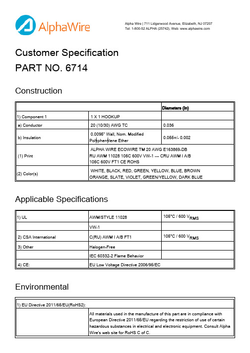
Customer Specification PART NO. 6714ConstructionApplicable Specifications Environmental Alpha Wire | 711 Lidgerwood Avenue, Elizabeth, NJ 07207 Tel: 1-800-52 ALPHA (25742), Web: Diameters (In)1) Component 1 1 X 1 HOOKUPa) Conductor 20 (10/30) AWG TC 0.036b) Insulation 0.0095" Wall, Nom. ModifiedPolyphenylene Ether0.055+/- 0.002(1) Print ALPHA WIRE ECOWIRE TM 20 AWG E163869-DB RU AWM 11028 105C 600V VW-1 --- CRU AWM I A/B 105C 600V FT1 CE ROHS(2) Color(s) WHITE, BLACK, RED, GREEN, YELLOW, BLUE, BROWN ORANGE, SLATE, VIOLET, GREEN/YELLOW, DARK BLUE1) UL AWM/STYLE 11028 105°C / 600 V RMSVW-12) CSA International C(RU) AWM I A/B FT1 105°C / 600 V RMS3) Other Halogen-FreeIEC 60332-2 Flame Behavior4) CE:EU Low Voltage Directive 2006/95/EC1) EU Directive 2011/65/EU(RoHS2):All materials used in the manufacture of this part are in compliance withEuropean Directive 2011/65/EU regarding the restriction of use of certainhazardous substances in electrical and electronic equipment. Consult AlphaWire's web site for RoHS C of C.PropertiesOther2) REACH Regulation (EC 1907/2006):This product does not contain Substances of Very High Concern (SVHC)listed on the European Union's REACH candidate list in excess of 0.1%mass of the item. For up-to-date information, please see Alpha's REACH SVHC Declaration.Physical & Mechanical Properties 1) Temperature Range -40 to 105°C 2) Bend Radius 10X Cable Diameter 3) Pull Tension 7.9 Lbs, MaximumElectrical Properties (For Engineering purposes only) 1) Voltage Rating 600 V RMS 2) Inductance 0.04 µH/ft, Nominal3) Conductor DCR 10.6 Ω/1000ft @20°C, NominalPackaging Flange x Traverse x Barrel (inches)a) 25000 DR 23 x 20 x 0 Max. 2 separate pieces; Min length/piece 5000 FT.b) 5000 FT 12 x 4.5 x 3.5 Continuous length c) 1000 FT 9 x 4.5 x 3.5 Continuous length d) 100 FT3.75 x 2 x 1.75 Continuous length[Spool dimensions may vary slightly]Notes:a) Certain colors and put-up combinations may only be available by special order, minimums may apply.Alpha Wire | 711 Lidgerwood Avenue, Elizabeth, NJ 07207Tel: 1-800-52 ALPHA (25742)Although Alpha Wire (“Alpha”) makes every reasonable effort to ensure there accuracy at the time of publication,information and specifications described herein are subject to errors or omissions and to changes without notice, and the listing of such information and specifications does not ensure product availability.Alpha provides the information and specifications herein on an “AS IS” basis, with no representations or warranties, whether express, statutory or implied. In no event will Alpha be liable for any damages (including consequential, indirect, incidental, special, punitive, or exemplary) whatsoever, even if Alpha had been advised of the possibility of such damages, whether in an action under contract, negligence or any other theory, arising out of or in connection with the use, or inability to use, the information or specifications described herein.ALPHA WIRE - CONFIDENTIAL AND PROPRIETARYNotice to persons receiving this document and/or technical information. This document is confidential and is the exclusive property of ALPHA WIRE, and is merely on loan and subject to recall by ALPHA WIRE at any time. By taking possession of this document, the recipient acknowledges and agrees that this document cannot be used in any manner adverse to the interests of ALPHA WIRE, and that no portion of this document may be copied or otherwise reproduced without the prior written consent of ALPHA WIRE. In the case of conflicting contractual provisions, this notice shall govern the status of this document. <br /><br />©2019 ALPHA WIRE - all rights reserved.EU/China ROHS CERTIFICATE OF COMPLIANCETo Whom It May Concern:Alpha Wire Part Number: 67146714, RoHS-Compliant Commencing With 7/1/2009 ProductionNote: all colors and put-upsThis document certifies that the Alpha part number cited above is manufactured in accordance with Directive 2011/65/EU of the European Parliament, better known as the RoHS Directive (commonly known as RoHS 2), with regards to restrictions of the use of certain hazardous substances used in the manufacture of electrical and electronic equipment. This certification extends to amending Directive 2015/863/EU which expanded the list of restricted substances to 10 items (commonly known as RoHS 3) The reader is referred to these Directives for the specific definitions and extents of the Directives. No Exemptions are required for RoHS Compliance on this item. Additionally, Alpha certifies that the listed part number is in compliance with China RoHS “Marking for Control of Pollution by Electronic Information Products” standard SJ/T 11364-2014.Substance Maximum Control ValueLead0.1% by weight (1000 ppm)Mercury0.1% by weight (1000 ppm)Cadmium0.01% by weight (100 ppm)Hexavalent Chromium0.1% by weight (1000 ppm )Polybrominated Biphenyls (PBB)0.1% by weight (1000 ppm)Polybrominated Diphenyl Ethers (PBDE) ,Including Deca-BDE0.1% by weight (1000 ppm)Bis(2-ethylhexyl) phthalate (DEHP)0.1% by weight (1000 ppm)Butyl benzyl phthalate (BBP)0.1% by weight (1000 ppm)Dibutyl phthalate (DBP) 0.1% by weight (1000 ppm)Diisobutyl phthalate (DIBP)0.1% by weight (1000 ppm)The information provided in this document and disclosure is correct to the best of Alpha Wire's knowledge, information and belief at the date of its release. The information provided is designed only as a general guide for the safe handling, storage, and any other operation of the product itself or the one that it will become part of. The intent of this document is not to be considered a warranty or quality specification. Regulatory information is for guidance purposes only. Product users are responsible for determining the applicability of legislation and regulations based on their individual usage of the product.Authorized Signatory for the Alpha Wire:Dave Watson, Director of Engineering & QA4/11/2022Alpha Wire711 Lidgerwood Ave.Elizabeth, NJ 07207Tel: 1-908-925-8000。
EB-9V Battery-powered Automatic Flashing Module Us

KUTAI ELECTRONICS INDUSTRY CO., LTD.TEL : +886-7-8121771FAX : +886-7-8121775Website : Headquarters : No.3, Ln. 201, Qianfu St., Qianzhen Dist., Kaohsiung City 806037, TaiwanEB-9VBattery-powered Automatic Flashing ModuleUser Manual※Lithium Battery Not IncludedSECTION 1 : FEATURES●No external battery or DC power supply required, excitation power provided by an internal battery.●Small size, light weight and easy installation saving labor.●Automatic excitation detection requires no manual operation or settings.●Very low static power consumption, Up to 3 years between battery replacement in standby mode.●Excitation function repeats 3 times and stops automatically when voltage is established.●Battery low voltage indicator reminds user to change battery.●Up to three repeat flashing attempts and will automatically stop when voltage builds up.●Excitation failure indicator. Resets automatically when voltage builds up or engine is stopped.●Battery reverse polarity protection.●Excitation field F+, F- Reverse Polarity Protection.●Built in manual forced excitation push button.SECTION 2 : SPECIFICATIONSensing Voltage Input Lithium Battery SpecificationsVoltage 1 300 Vac 1 phase 2 wire Model no. Ultralife U9VL-J-PFrequency 50/60 Hz Voltage 9 VdcCurrent Normal discharge 700 mA Max Excitation Output Pulse discharge 1050 mA MaxVoltage 9 Vdc Capacity 1200 mAh @ 23 ˚CCurrent 700 mA Max.Service Life 10 yearsFlashing Output Conditions EnvironmentWhen voltage less than 10 Vac at frequency greater Operating Temperature -20 to +60 ˚Cthan 40 Hz Storage Temperature -40 to +60 ˚CRelative Humidity Max. 95%Flashing Output Time Vibration 5 Gs @ 60 HzExcitation output 5 seconds. Up to 3 attempts at 5second intervals Dimensions87.0 (L) x 41.5 (W) x 61.7 (H) mmTime Between Battery Change 3.42 (L) x 1.63 (W) x 2.43 (H) inch3 years Max. Weight( Use only Ultralife U9VL-J-P lithium battery ) 85 g +/- 2%0.19 lb +/- 2%___________________________________________________________________________________________ 2EB-9V___________________________________________________________________________________________ EB-9V3SECTION 3 : Explanation of Terminals, Indicators, and AdjustmentsSECTION 4 : Dimensions / Connection DiagramB AExternal DimensionsConnection Diagram※ Appearance and specifications of products are subject to change for improvement without prior notice.Low DC :Battery Voltage Low (red) Blinks every 5 sec when battery voltage lowPower :Power indicator (green)Blinks every 5 sec in standby modeIlluminates continuously during excitation output F+、F-:Excitation OutputConnects to generator excitation field Sensing Voltage input :1 300 VacMounting Holes * 2Manual :Manual forced excitation push button Pressing this button forces excitation output※ Both Power and Low DC indicators will blink when excitation fails。
欧洲品牌Preventa的XPSUS12AP安全自动化模块产品说明书
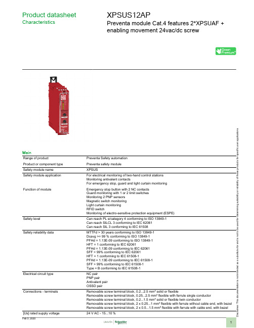
Product datasheetCharacteristicsXPSUS12APPreventa module Cat.4 features 2*XPSUAF +enabling movement 24vac/dc screwMainRange of productPreventa Safety automation Product or component type Preventa safety module Safety module name XPSUSSafety module applicationFor electrical monitoring of two-hand control stations Monitoring antivalent contactsFor emergency stop, guard and light curtain monitoring Function of moduleEmergency stop button with 2 NC contacts Guard monitoring with 1 or 2 limit switches Monitoring 2 PNP sensors Magnetic switch monitoring Light curtain monitoring RFID switchMonitoring of electro-sensitive protection equipment (ESPE)Safety levelCan reach PL e/category 4 conforming to ISO 13849-1Can reach SILCL 3 conforming to IEC 62061Can reach SIL 3 conforming to IEC 61508Safety reliability dataMTTFd > 30 years conforming to ISO 13849-1Dcavg >= 99 % conforming to ISO 13849-1PFHd = 1.13E-09 conforming to ISO 13849-1HFT = 1 conforming to IEC 62061PFHd = 1.13E-09 conforming to IEC 62061SFF > 99% conforming to IEC 62061HFT = 1 conforming to IEC 61508-1PFHd = 1.13E-09 conforming to IEC 61508-1SFF > 99% conforming to IEC 61508-1Type = B conforming to IEC 61508-1Electrical circuit typeNC pair PNP pairAntivalent pair OSSD pairConnections - terminalsRemovable screw terminal block, 0.2...2.5 mm² solid or flexibleRemovable screw terminal block, 0.25...2.5 mm² flexible with ferrule single conductor Removable screw terminal block, 0.2...1.5 mm² solid or flexible twin conductorRemovable screw terminal block, 2 x 0.25...1 mm² flexible with ferrule without cable end, with bezel Removable screw terminal block, 2 x 0.5...1.5 mm² flexible with ferrule with cable end, with bezel [Us] rated supply voltage24 V AC - 15...10 %i s c l a i m e r : T h i s d o c u m e n t a t i o n i s n o t i n t e n d e d a s a s u b s t i t u t e f o r a n d i s n o t t o b e u s e d f o r d e t e r m i n i n g s u i t a b i l i t y o r r e l i a b i l i t y o f t h e s e p r o d u c t s f o r s p e c i f i c u s e r a p p l i c a t i o n s24 V DC - 20...20 %ComplementarySynchronisation time between inputs0.5 s2 s4 sType of start Automatic/manual/monitoredPower consumption in W2 W 24 V DCPower consumption in VA 5.0 VA 24 V AC 50/60 HzInput protection type Internal, electronicSafety outputs 2 NOSafety inputs 2 safety input 24 V DC 5 mAMaximum line resistance60 OhmInput compatibility Normally closed circuit conforming to ISO 14119XC limit switch conforming to ISO 14119Mechanical contact conforming to ISO 14119Normally closed circuit conforming to ISO 13850Antivalent pair conforming to ISO 14119OSSD pair conforming to IEC 61496-1-2Two-hand control conforming to EN 574/ISO 13851-III A3-wire proximity sensors PNPOutput type Relay output : 250 V AC, AC-1, B300 for normally open relay contactRelay output : 250 V AC, AC-15, D300 for normally closed relay contactRelay output : 24 V DC, DC-1, R300 for normally open relay contactRelay output : 24 V DC, DC-13, R300 for normally closed relay contact[Ie] rated operational current5 A AC-1 for normally open relay contact3 A AC-15 for normally open relay contact5 A DC-1 for normally open relay contact3 A DC-13 for normally open relay contact3 A AC-1 for normally closed relay contact1 A AC-15 for normally closed relay contact3 A DC-1 for normally closed relay contact1 A DC-13 for normally closed relay contactControl outputs 3 on/off configurable pulsed outputInput/Output type Semiconductor pulsed diagnostic output 24 V DC, 20 mA Z1, not safety-related8 A[Ith] conventional free air thermalcurrentAssociated fuse rating10 A gG for NO relay output circuit conforming to IEC 60947-1Minimum output current10 mA for relay outputMinimum output voltage12 V for relay output20 msMaximum response time on inputopen[Ui] rated insulation voltage250 V (pollution degree 2) conforming to EN/IEC 60947-1[Uimp] rated impulse withstand voltage4 kV overvoltage category II conforming to EN/IEC 60947-1Local signalling LED (green)power ON:LED (red)error:LED (yellow)safety output status:LED (yellow)start input:LED (yellow)safety input S12:LED (yellow)safety input S13:LED (yellow)safety input S22:LED (yellow)safety input S23:Mounting support35 mm symmetrical DIN railDepth120 mmHeight100 mmWidth22.5 mmProduct weight0.200 kgEnvironmentStandards IEC 60947-5-1IEC 61508-1 functional safety standardIEC 61508-2 functional safety standardIEC 61508-3 functional safety standardIEC 61508-4 functional safety standardIEC 61508-5 functional safety standardIEC 61508-6 functional safety standardIEC 61508-7 functional safety standardISO 13849-1 functional safety standardIEC 62061 functional safety standardProduct certifications TÜVCULusIP degree of protection IP20 (terminals) conforming to EN/IEC 60529IP40 (housing) conforming to EN/IEC 60529IP54 (mounting area) conforming to EN/IEC 60529Ambient air temperature for storage-25…85 °CRelative humidity5…95 % non-condensingOffer SustainabilitySustainable offer status Green Premium productEU RoHS Directive Pro-active compliance (Product out of EU RoHS legal scope)EU RoHS DeclarationMercury free YesRoHS exemption information YesChina RoHS Regulation China RoHS declarationEnvironmental Disclosure Product Environmental ProfileCircularity Profile End of Life InformationWEEE The product must be disposed on European Union markets following specific waste collection andnever end up in rubbish binsContractual warrantyWarranty18 monthsDimensions DrawingsDimensionsFront and Side Views(A) :Product drawing(B) :Screw clamp terminal(C) :Side view(1) :Removable terminal blocks, top(2) :Removable terminal blocks, bottom(3) :LED indicators(4) :Start function selector(5) :Function selector(6) :Connector for optional output extension module (lateral)(7) :Sealable transparent coverMounting to DIN railScrew-mountingConnections and SchemaWiring Drawing(1) :A1-A2 (Power supply)(2) :S11-S12-S13-S21-S22-S23 (Single-channel safety input)(3) :Y1-Y2 (Start)Output13-23-14-24 :EXT :Connector for optional extension moduleB2 :Common ground terminalZ1 :Pulsed output for diagnostics, not safety-related。
美国国家环保局EPA方法要点和推荐仪器
美国国家环保局EPA方法要点和推荐仪器EPA方法218.6离子色谱测定在饮用水、地下水和工业废水中的水溶性铬(1994年修订版3.3)应用范围测定饮用水、地下水和工业废水中的水溶性六价铬(如CrO2-4),这种方法的检测下限为0.4μg/L。
样品中如果含有大量的阴离子物质如硫酸或氯离子可能会引起色谱柱过载。
样品如果含有大量有机物或硫离子可能会引起可溶性的六价铬快速还原为三价铬。
样品贮存在4℃,在24小时内分析。
方法采用离子色谱法分析。
方法要点:水样经0.45μm滤膜过滤后,用浓缓冲溶液调节pH为9-9.5。
样品的测量体积为50-250μL进样到离子色谱。
保护柱去除样品中的有机物,六价铬以CrO2-4形式,在高容量的阴离子交换分离柱上分离,六价铬用双苯基苄巴脲柱后衍生,然后在530nm波长下检测有色络合物。
建议采用的仪器条件保护柱:Dionex IonPac NG1或与之相同的色谱柱分离柱:Dionex IonPac AS7或与之相同的色谱柱阴离子抑制器装置:Dionex Anion MicroMembrane Suppressor,其它抑制器必须有足够低的检测限和足够的基线稳定性。
色谱条件:色谱柱:保护柱-Dionex IonPac NG1, 分离柱-Dionex IonPac AS7淋洗液:250mM (NH4)2SO4, 100mM NH4OH, 流速=1.5 mL/min柱后试剂:2mM双苯基苄巴脲,10% v/v甲醇,1N 硫酸,流速=0.5 mL/min 检测器:可见光530nm保留时间:3.8 分钟离子色谱测定无机阴离子(1993年八月,修订版2.2)应用范围1.可测定的阴离子包括A部分:溴离子,氯离子,氟离子,硝酸根,亚硝酸根,磷酸根,硫酸B部分:溴酸根,亚氯酸根,氯酸根2.基体包括:饮用水,地表水,民用水和工业废水,地下水,试剂用水,固体浸出液方法要点1.小量样品,一般2-3mL注入离子色谱,阴离子采用一个系统含有保护柱,分离柱,抑制器和电导检测器进行分离和检测。
- 1、下载文档前请自行甄别文档内容的完整性,平台不提供额外的编辑、内容补充、找答案等附加服务。
- 2、"仅部分预览"的文档,不可在线预览部分如存在完整性等问题,可反馈申请退款(可完整预览的文档不适用该条件!)。
- 3、如文档侵犯您的权益,请联系客服反馈,我们会尽快为您处理(人工客服工作时间:9:00-18:30)。
METHOD 9056A DETERMINATION OF INORGANIC ANIONS BY ION CHROMATOGRAPHYSW-846 is not intended to be an analytical training manual. Therefore, methodprocedures are written based on the assumption that they will be performed by analysts who are formally trained in at least the basic principles of chemical analysis and in the use of the subject technology.In addition, SW-846 methods, with the exception of required method use for the analysis of method-defined parameters, are intended to be guidance methods which contain general information on how to perform an analytical procedure or technique which a laboratory can use as a basic starting point for generating its own detailed Standard Operating Procedure (SOP),either for its own general use or for a specific project application. The performance data included in this method are for guidance purposes only, and are not intended to be and must not be used as absolute QC acceptance criteria for purposes of laboratory accreditation.1.0SCOPE AND APPLICATION1.1This method addresses the sequential determination of chloride (Cl G ), fluoride (F G ),bromide (Br G ), nitrate (NO 3G ), nitrite (NO 2G ), phosphate (PO 43G ), and sulfate (SO 42G ) anions in aqueous samples, such as drinking water, wastewater, aqueous extracts of solids, and the collection solutions from the bomb combustion of solid waste samples (Method 5050).1.2The lower limit of quantitation (LLOQ), the lowest concentration level that can be measured within stated accuracy limits, varies for each individual analyte anion and as a function of sample size.1.3Maximum column loading should not exceed approximately 500 ppm total anions when using a 50-µL sample loop and the columns listed in Sec. 6.1. Dilution of samples may allow higher concentration samples to be analyzed.1.4 Analysts should consult the disclaimer statement at the front of the manual and the information in Chapter Two for guidance on the intended flexibility in the choice of methods,apparatus, materials, reagents, and supplies, and on the responsibilities of the analyst fordemonstrating that the techniques employed are appropriate for the analytes of interest, in the matrix of interest, and at the levels of concern.In addition, analysts and data users are advised that, except where explicitly specified in a regulation, the use of SW-846 methods is not mandatory in response to Federal testingrequirements. The information contained in this method is provided by EPA as guidance to be used by the analyst and the regulated community in making judgments necessary to generate results that meet the data quality objectives for the intended application.1.5Use of this method is restricted to use by, or under supervision of, properlyexperienced and trained personnel. Each analyst must demonstrate the ability to generate acceptable results with this method.2.0SUMMARY OF METHOD2.1 A small volume of aqueous sample is injected into an ion chromatograph to flush and fill a constant-volume sample loop. The sample is then injected into a flowing stream of carbonate-bicarbonate eluent.2.2The sample is pumped through two different ion exchange columns, then a conductivity suppressor device, and into a conductivity detector. The two ion exchange columns, a precolumn or guard column and a separator column, are packed with an anion exchange resin. Ions are separated into discrete bands based on their affinity for the exchange sites of the resin. The conductivity suppressor is an ion exchange-based device that reduces the background conductivity of the eluent to a low or negligible level and simultaneously converts the anions in the sample to their more conductive acid forms. The separated anions in their acid forms are measured using an electrical conductivity cell. Anion identification is based on the comparison of analyte signal peak retention times relative to those of known standards. Quantitation is accomplished by measuring the peak area and comparing it to a calibration curve generated from known standards.3.0DEFINITIONSRefer to Chapter One, Chapter Three, and the manufacturer's instructions for definitions that may be relevant to this procedure.4.0INTERFERENCES4.1Any species with a retention time similar to that of the desired anion will interfere. Large quantities of ions eluting close to the anion of interest will also result in an interference. Separation can be improved by adjusting the eluent concentration and/or flow rate. Sample dilution and/or the use of the method of standard additions can also be used. For example, high levels of organic acids that may interfere with inorganic anion analysis may be present in industrial wastes. Two common species, formate and acetate, elute between fluoride and chloride.4.2The water dip or negative peak that elutes near, and can interfere with, the fluoride peak can usually be eliminated by the addition of the equivalent of 1 mL of concentrated eluent (100 times more concentrated than the solution described in Sec. 7.3) to 100 mL of each standard and sample.4.3Method interferences may be caused by contaminants in the reagent water, reagents, glassware, and other sample processing apparatus that lead to discrete artifacts or elevated baselines in ion chromatograms. All of these materials must be demonstrated to be free from interferences under the conditions of the analysis by analyzing method blanks (Sec. 9.3.1). Specific selection of reagents and purification of solvents by distillation in all-glass systems may be necessary. Refer to Chapter Three for general guidance on the cleaning of glassware.4.4Samples that contain particles larger than 0.45 µm and reagent solutions that contain particles larger than 0.20 µm require filtration to prevent damage to instrument columns and flow systems. The associated method blanks must also be filtered if any samples or reagents have undergone filtration.4.5The acetate, formate, and other monovalent organic acid anion elute early in the chromatographic run and can interfere with fluoride. The retention times of anions may differ when large amounts of acetate are present. Therefore, this method is not recommended for leachates of solid samples where acetate is used for pH adjustment.5.0SAFETY5.1This method does not address all safety issues associated with its use. Thelaboratory is responsible for maintaining a safe work environment and a current awareness file of OSHA regulations regarding the safe handling of the chemicals listed in this method. A reference file of material safety data sheets (MSDSs) should be available to all personnel involved in these analyses.5.2The toxicity or carcinogenicity of each reagent used in this method has not been fully established. Each chemical should be regarded as a potential health hazard and exposure should be as low as reasonably achievable.6.0EQUIPMENT AND SUPPLIESThe mention of trade names or commercial products in this manual is for illustrativepurposes only, and does not constitute an EPA endorsement or exclusive recommendation for use. The products and instrument settings cited in SW-846 methods represent those products and settings used during method development or subsequently evaluated by the Agency. Glassware, reagents, supplies, equipment, and settings other than those listed in this manual may be employed provided that method performance appropriate for the intended application has been demonstrated and documented.This section does not list common laboratory glassware (e.g., beakers and flasks).6.1Ion chromatograph -- Capable of delivering 1 to 5 mL of eluent per min at apressure of 1000 to 4000 psi (6.5 to 27.5 MPa). The chromatograph must be equipped with an injection valve, a 25- to 100-µL sample loop, and set up with the following components, as schematically illustrated in Figure 1.6.1.1Precolumn -- A guard column placed before the separator column toprotect the separator column from being fouled by particulates or certain organicconstituents. An example of a suitable column is the Dionex IonPac ® AG4A-SC, orequivalent.6.1.2Separator (or analytical) column -- A column packed with an anionexchange resin, suitable for resolving F G , Br G , Cl G , NO 3G , NO 2G , PO 43G , and SO 42G . An example of a suitable column is the Dionex IonPac ® AS4A-SC, or equivalent.6.1.3Conductivity suppressor -- An ion exchange-based device that is capableof converting the eluent and separated anions to their respective acid forms. Examples of suitable suppressors include the Dionex AMMS-II or ASRS Ultra, or equivalent.6.1.4Conductivity detector -- A low-volume, flow-through, temperature-compensated, electrical conductivity cell (approximately 1.25-µL volume), equipped with a meter capable of reading from 0 to 1,000 Siemens/cm on a linear scale. An example of a suitable conductivity detector is the Dionex CD20 or equivalent.6.1.5Pump -- Capable of delivering a constant flow of approximately 1 to 5mL/min throughout the test and tolerating a pressure of 1000 to 4000 psi (6.5 to 27.5MPa).6.2Syringe -- Minimum capacity of 1 mL, equipped with a male pressure fitting.6.3Appropriate chromatographic data and control software to acquire data. Dionex PeakNet was used to record and process the chromatogram shown in Figure 2. Alternatively,an integrator or recorder can be used to integrate the area under the chromatographic peaks. If an integrator is used, the maximum area measurement must be within the linear range of the integrator. The recorder should be compatible with the detector output with a full-scale response time of 2 seconds or less.6.4Analytical balance -- Capable of weighing to the nearest 0.0001 g.6.5Pipets, Class A volumetric flasks, beakers -- Assorted sizes.7.0REAGENTS AND STANDARDS7.1Reagent-grade chemicals must be used in all tests. Unless otherwise indicated, it is intended that all reagents conform to the specifications of the Committee on Analytical Reagents of the American Chemical Society, where such specifications are available. Other grades may be used, provided it is first ascertained that the reagent is of sufficiently high purity to permit its use without lessening the accuracy of the determination.7.2Reagent water -- All references to water in this method refer to reagent water, as defined in Chapter One.7.3Eluent, 1.7 mM NaHCO 3/1.8 mM Na 2CO 3 -- Dissolve 0.2856 g of sodiumbicarbonate (1.7 mM NaHCO 3) and 0.3816 g of sodium carbonate (1.8 mM Na 2CO 3) in reagent water and dilute to 2 L with reagent water or follow manufacturer’s guidance for the proper eluent for each specific column.7.4Conductivity suppressor regenerant solution (25 mM H 2SO 4), if required -- Add 2.8mL of concentrated sulfuric acid (H 2SO 4) to 4 L of reagent water.7.5Stock solutions (1,000 mg/L) -- Certified standards may also be purchased and used as stock solutions. Stock solutions are stable for at least 1 month when stored at #6 E C.7.5.1Bromide stock solution (1.00 mL = 1.00 mg of Br G ) -- Dry approximately 2g of sodium bromide (NaBr) for 6 hr at 150 °C, and cool in a desiccator. Dissolve 1.2877 g of the dried salt in reagent water, and dilute to 1 L with reagent water in a Class Avolumetric flask.7.5.2Chloride stock solution (1.00 mL = 1.00 mg of Cl G ) -- Dry sodium chloride(NaCl) for 1 hr at 600 °C, and cool in a desiccator. Dissolve 1.6484 g of the dry salt in reagent water, and dilute to 1 L with reagent water in a Class A volumetric flask.7.5.3Fluoride stock solution (1.00 mL = 1.00 mg of F G ) -- Dissolve 2.2100 g ofsodium fluoride (NaF) in reagent water, and dilute to 1 L with reagent water in a Class A volumetric flask. Store in a chemical-resistant glass or polyethylene container.7.5.4Nitrate stock solution (1.00 mL = 1.00 mg of NO 3G ) -- Dry approximately 2g of sodium nitrate (NaNO 3) at 105 °C for 24 hr. Dissolve exactly 1.3707 g of the dried salt in reagent water, and dilute to 1 L with reagent water in a Class A volumetric flask.7.5.5Nitrite stock solution (1.00 mL = 1.00 mg of NO 2G ) -- Place approximately2 g of sodium nitrate (NaNO 2) in a 125 mL beaker and dry to constant weight (about 24 hr)in a desiccator containing concentrated H 2SO 4. Dissolve 1.4998 g of the dried salt inreagent water, and dilute to 1 L with reagent water in a Class A volumetric flask. Store in a sterilized glass bottle. Refrigerate and prepare monthly.NOTE: Nitrite is easily oxidized, especially in the presence of moisture, and only freshreagents are to be used.NOTE:Prepare sterile bottles for storing nitrite solutions by heating them for 1 hr at 170°C in an air oven.7.5.6Phosphate stock solution (1.00 mL = 1.00 mg of PO 43G ) -- Dissolve1.4330 g of potassium dihydrogen phosphate (KH 2PO 4) in reagent water, and dilute to 1 L with reagent water in a Class A volumetric flask.7.5.7Sulfate stock solution (1.00 mL = 1.00 mg of SO 42G ) -- Dissolve 1.4790 gof the dried salt in reagent water, and dilute to 1 L with reagent water in a Class Avolumetric flask.7.6Anion calibration standardsPrepare a blank and at least three combination anion calibration standards containing the anions of interest. The combination anion solutions must be prepared in Class A volumetric flasks (see Table 2). Calibration standards should be prepared weekly, except for those that contain nitrite and phosphate, which should be prepared fresh daily. The validity of standards can be confirmed through the analysis of a freshly prepared ICV (Sec. 10.6).7.6.1Prepare the high-range calibration standard solution by combining thevolumes of each anion stock solution specified in Sec. 7.5 in a Class A volumetric flask and diluting the mixture to 1 L with reagent water.7.6.2Prepare the intermediate-range calibration standard solution by diluting10.0 mL of the high-range calibration standard solution (Sec. 7.6.1) to 100 mL withreagent water.7.6.3Prepare the low-range calibration standard solution by diluting 20.0 mL ofthe intermediate-range calibration standard solution (Sec. 7.6.2) to 100 mL with reagent water.8.0SAMPLE COLLECTION, PRESERVATION, AND STORAGE8.1See the introductory material to Chapter Three, "Inorganic Analytes."8.2Preserve samples at #6 E C. If nitrite, nitrate and phosphate are analytes ofinterest, samples should be analyzed within 48 hr of collection. A longer holding time may be appropriate for chloride, fluoride, sulfate and bromide.9.0QUALITY CONTROL9.1Refer to Chapter One for guidance on quality assurance (QA) and quality control (QC) protocols. When inconsistencies exist between QC guidelines, method-specific QC criteria take precedence over both technique-specific criteria and those criteria given in Chapter One, and technique-specific QC criteria take precedence over the criteria in Chapter One. Any effort involving the collection of analytical data should include development of a structured and systematic planning document, such as a Quality Assurance Project Plan (QAPP) or a Sampling and Analysis Plan (SAP), which translates project objectives and specifications into directions for those that will implement the project and assess the results. Each laboratory should maintain a formal quality assurance program. The laboratory should also maintain records to document the quality of the data generated. All data sheets and quality control data should be maintained for reference or inspection.9.2Initial demonstration of proficiencyEach laboratory must demonstrate initial proficiency with the sample preparation and determinative method combination it utilizes by generating data of acceptable accuracy and precision for the target analyte in a clean matrix. The laboratory must also repeat the demonstration of proficiency whenever new staff members are trained or significant changes in instrumentation are made. See Method 8000 for information on how to accomplish an initial demonstration of proficiency.9.3Sample quality control for preparation and analysis.The laboratory must also have procedures for documenting the effect of the matrix on method performance (precision, accuracy, method sensitivity). At a minimum, the laboratory should include the analysis of QC samples including a method blank, a matrix spike, a duplicate, and a laboratory control sample (LCS) in each analytical batch. Any method blanks, matrix spike samples, replicate samples and LCSs should be subjected to the same analytical procedures (Sec. 11.0) as those used on actual samples.The following should be included within each analytical batch.9.3.1Initially, before processing any samples, the analyst should demonstratethat all parts of the equipment in contact with the sample and reagents areinterference-free. This is accomplished through the analysis of a method blank. As acontinuing check, each time samples are extracted, cleaned up, and analyzed, and when there is a change in reagents, a method blank should be prepared and analyzed for the compounds of interest as a safeguard against chronic laboratory contamination. If a peak is observed within the retention time window of any analyte that would prevent thedetermination of that analyte, determine the source and eliminate it, if possible, beforeprocessing the samples. The blanks should be carried through all stages of samplepreparation and analysis. If the method blank does not contain target analytes at a level that interferes with the project-specific DQOs, then the method blank would be considered acceptable.In the absence of project-specific DQOs, if the blank is less than 10% of the lower limit of quantitation check sample concentration, less than 10% of the regulatory limit, or less than 10% of the lowest sample concentration for each analyte in a given preparation batch, whichever is greater, then the method blank is considered acceptable. If themethod blank cannot be considered acceptable, the method blank should be re-run once, and if still unacceptable, then all samples after the last acceptable method blank should be reprepared and reanalyzed along with the other appropriate batch QC samples. Theseblanks will be useful in determining if samples are being contaminated. If the methodblank exceeds the criteria, but the samples are all either below the reporting level or below the applicable action level or other DQOs, then the sample data may be used despite the contamination of the method blank. Refer to Chapter One for the proper protocol when analyzing blanks.9.3.2 A laboratory control sample (LCS) should be included with eachanalytical batch. The LCS consists of an aliquot of a clean (control) matrix similar to the sample matrix and of the same weight or volume. The LCS is spiked with the sameanalytes at the same concentrations as the matrix spike, when appropriate. Acceptance criteria should be set at a laboratory-derived limit developed through the use of historical analyses, or set by the method quality objectives (MQOs)/data quality objectives (DQOs)of the project. In the absence of historical data or well-defined MQOs/DQOs, this limit should be set at ± 20% of the spiked value. Acceptance limits derived from historical data must be no wider that ± 20%. Consult Method 8000 for further information on developing acceptance criteria for the LCS. When the result of a matrix spike analysis indicates a potential problem due to the sample matrix itself, the LCS result is used to verify that the laboratory can perform the analysis in a clean matrix. If the LCS result is not acceptable,then the LCS must be reanalyzed once. If the results are still unacceptable, then allsamples analyzed after the last acceptable LCS must be reprepared and reanalyzed.9.3.3Matrix spike, unspiked duplicate, or matrix spike duplicate (MS/Dup orMS/MSD)Documenting the effect of the matrix, for a given preparation batch consisting ofsimilar sample characteristics, should include the analysis of at least one matrix spike and one duplicate unspiked sample or one matrix spike/matrix spike duplicate pair. Thedecision on whether to prepare and analyze duplicate samples or a matrix spike/matrix spike duplicate must be based on a knowledge of the samples in the sample batch or as noted in the project-specific planning documents. If samples are expected to containtarget analytes, then laboratories may use one matrix spike and a duplicate analysis of an unspiked field sample. If samples are not expected to contain target analytes, laboratories should use a matrix spike and matrix spike duplicate pair.9.3.3.1At least one matrix spike (MS) sample should be analyzedwithin each analysis batch for determining method bias and/or sample matrixeffects. The MS percent recovery (%R) is calculated as follows:()%R MSSR SR SA=−×100Where:MSSR = MS Sample ResultSR = Sample ResultSA = Spike AddedWhen the sample concentration is less than the LLOQ, use SR = 0 for purposes ofcalculating %R.9.3.3.2The method control limits for %R are 80 - 120. Alternate limitsmay be used provided that they meet the data quality objectives of the specificproject. Failure to meet the MS %R criteria indicates potential problems with theanalytical system and/or sample matrix effects and corrective action should betaken to investigate and resolve the problem. If %R is outside the control limitsand all other QC data is within limits, a matrix effect is suspected. The associateddata should be flagged according to project specifications or noted in thecomments section of the report.9.3.3.3 A duplicate or matrix spike duplicate (MSD) should beanalyzed within every analytical batch in order to establish the precision of themethod. Calculate the relative percent difference (RPD) between the sample andduplicate result as follows.()RPD S D S D =−−×/2100Where:RPD =Relative Percent Difference S =Sample or MS Sample Result D =Duplicate or MSD Result9.3.3.4The method control limit for RPD is 15% for all sampleconcentrations that are near or above the mid-range of the calibration curve. Themethod control limit for RPD is 50% for sample concentrations that are near thelow-range of the calibration curve. Alternate limits may be used provided that theymeet the data quality objectives of the specific project. Failure to meet theduplicate RPD criteria indicates potential problems with the analytical systemand/or sample matrix effects and corrective action should be taken to investigateand resolve the problem.10.0CALIBRATION AND STANDARDIZATION10.1Establish ion chromatographic operating parameters equivalent to those indicated in Table 1, or as recommended by the manufacturer.10.2 For each analyte of interest, prepare a blank and calibration standards at aminimum of three concentrations by adding accurately measured volumes of one or more stock standards to a Class A volumetric flask and diluting to volume with reagent water. A sufficient number of standards must be analyzed to allow an accurate calibration curve to be established. One of the standards should be representative of a concentration at or below the laboratory’s lower limit of quantitation (LLOQ ). The other standards should correspond to the range of concentrations expected in the sample or should define the working range of the detector.10.3The laboratory should establish the LLOQ for each analyte as the lowest reliable laboratory reporting concentration or in most cases the lowest point in the calibration curve which is less than or equal to the desired regulatory action levels, based on the stated project requirements. Analysis of a standard prepared at the LLOQ concentration levels or use of the LLOQs as the lowest point calibration standard provides confirmation of the establishedsensitivity of the method. The LLOQ recoveries must be within 50% of the true values to verify the data reporting limit.10.4After a stable baseline is obtained (approximately 30 min), begin to injectstandards starting with the lowest concentration standard and increasing in concentration to the highest standard. Use a fixed injection volume between 25 and 100 µL (determined by injection loop volume) for each calibration standard. Record the peak area responses and retention times for each analyte.10.5 Establish the individual analyte calibration curves by plotting the peak arearesponses for each standard against the corresponding concentrations. Use a least squares -linear regression to calculate the calibration curve formula. The linear correlation coefficient should be equal to or greater than 0.995. A weighted least squares regression may also be performed using 1/concentration or 1/(concentration)2 as the weighting factor. The acceptance criterion for the calibration curve should be a correlation coefficient of 0.995 or higher. Refer to Method 8000 for additional guidance on calibration procedures.10.6 Verify the accuracy of the initial calibration curve by analyzing an initial calibration verification (ICV) standard. The ICV standard must be prepared from an independent (second source) material at or near the mid-range of the calibration curve. The acceptance criteria for the ICV standard must be no greater than ± 10% of its true value. If the calibration curve cannot be verified within the specified limits, the cause must be determined and the instrumentrecalibrated before samples are analyzed. The analysis data for the ICV must be kept on file with the sample analysis data.10.7Verify the accuracy of the working calibration curve on each working day, orwhenever the anion eluent composition or strength is changed, and for every batch of 10 or less samples, through the analysis of a continuing calibration verification (CCV) standard. The CCV should be made from the same material as the initial calibration standards at or near mid-range. The acceptance criteria for the CCV standard should be ± 10% of its true value for thecalibration to be considered valid. If the CCV standard result does not meet the acceptance criterion, sample analysis must be discontinued, the cause determined, and the instrument recalibrated. All samples analyzed after the last acceptable CCV should be reanalyzed. The analysis data for the CCV should be kept on file with the sample analysis data.10.8Nonlinear response can result when the separator column capacity is exceeded (overloading). Maximum column loading should not exceed approximately 500 ppm total anions when using a 50-µL sample loop and the columns listed in Sec. 6.1.11.0PROCEDURE11.1Sample preparationWhen aqueous samples are injected, the water passes rapidly through the columns, and a negative "water dip" is observed that may interfere with the early-eluting fluoride and/or chloride ions. In combustate samples generated by bomb combustion (Method 5050), the water dip should not be observed, since the collecting solution is a concentrated eluent solution that will be equivalent to the eluent strength when diluted to 100-mL with reagent water according to the bomb combustion procedure. Any dilutions required in analyzing other water samples should be made with the eluent solution. The water dip, if present, may be removed by addingconcentrated eluent to all samples and standards such that the final sample/standard solution is equivalent to the eluent concentration. When a manual system is used, it is necessary to micropipet concentrated buffer into each sample. The recommended procedure follows:11.1.1Prepare a 100-mL stock of eluent 100 times a normal concentration bydissolving 1.428 g of NaHCO 3 and 1.908 g of Na 2CO 3 in 100 mL of reagent water or use。