A300产品规格书20120518
品牌:Honeywell 产品名:HMR3000 型号:HHMR3000 品牌型号说明书

Digital Compass Solution HMR3000The Honeywell HMR3000 is a digital compass module that provides heading, pitch, and roll outputs for navigation. Three Honeywell’s magneto -resistive sensors are oriented in orthogonal directions to measure the vector components of earth’s magnetic field. A fluid tilt sensor is employed to determine a gravitational reference. These solid-state sensors create a strapdown compass that is both rugged and reliable. The data output is serial full-duplex RS-232 or half-duplex RS-485 with 1200 to 19,200 data rates.Applications include: Compassing & Navigation, Dead Reckoning Backup to GPS Systems, Marine Navigation, Antenna Positioning, and Land SurveyingA RS-232 development kit version is available that includes a windows compatible demo program (does not work with RS-485 devices), interface cable, AC adapter and carrying case.Honeywell continues to maintain product excellence and performance by introducing innovative solid-state magnetic sensor solutions. These are highly reliable, top performance products that are delivered when promised. Honeywell’s magnetic sensor solutions provide real solutions you can count on.FEATURES & BENEFITS BLOCK DIAGRAMHigh Accuracy, <0.5° with 0.1° ResolutionWide Tilt Range of ±40° Up to 20 Updates per Second NMEA Standard Sentence Outputs Hard Iron Calibration RoutineRS-232 or RS-485 Serial Data Interfaces PCB or Aluminum Enclosure Options6-15 volt DC Unregulated Power SupplyInterfaceHMR3000SPECIFICATIONSPower SupplyTemperature(2) Tested at 25°C except stated otherwise.(3) Characterized(4) Parts stationary for 24 hours before testing(5) The HMR3000 Demo Kit is not available with the RS-485 interface because the software does not support half-duplex protocol2 HMR3000 3PIN CONFIGURATION(1) Power input shall only be applied to either Pin 8 (+5VDC) or Pin 9 (Unregulated +6 to+15VDC).(2) Exceeding the voltage specifications for Pin 8 may damage the HMR3000.RS-232 UNBALANCED I/O INTERCONNECTSRS-485 BALANCED I/O INTERCONNECTSHMR3000HOST PCHOST PCHMR3000HMR3000DATA COMMUNICATIONSThe HMR3000 serial communications are governed by a simple asynchronous, ASCII protocol modeled after the NMEA0183 standard. Either an RS-232 or an RS-485 electrical interface can be ordered. ASCII characters are transmitted and received using 1 start bit, 8 data bits (LSB first), no parity (MSB always 0), and 1 stop bit; 10 bits total per character. Thebaud rate defaults to 19,200 and can be reconfigured to 1200, 2400, 4800, 9600, 19200, 38400 bits per second. TheHMR3000 supports both standard NMEA 0183 and proprietary messages. Unsolicited NMEA messages are sent by theHMR3000 in Continuous Mode at the rates programmed in the EEPROM. HMR3000 also responds to all input messagesfrom the host. An HMR3000 response to a command input may be delayed due to transmission of an unsolicited output.The host computer must wait for HMR3000 to respond to the last command input before sending another command message. All communication from and to HMR3000 contain a two-character Checksum Field at the end of the data fields,and are denoted in the sentences by ‘hh’. The checksum assures the accuracy of the message transmitted. This checksumis also calculated per NMEA 0183 Standard.The RS-232 signals are single-ended undirectional levels that are sent received simultaneously (full duplex). One signal isfrom the host personal computer (PC) transmit (TD) to the HMR3000 receive (RD) data line, and the other is from theHMR3000 TD to the PC RD data line. When a logic one is sent, either the TD or RD line will drive to about +6 Volts referenced to ground. For a logic zero, the TD or RD line will drive to about –6 Volts below ground. Since the signals are transmitted and dependent on an absolute voltage level, this limits the distance of transmission due to line noise and signalto about 60 feet.When using RS-485(1), the signals are balanced differential transmissions sharing the same lines (half-duplex). This meansthat logic one the transmitting end will drive the B line at least 1.5 Volts higher than the A line. For a logic zero, the transmitting end will drive the B line at least 1.5 Volts lower than the A line. Since the signals are transmitted as difference voltage level, these signals can withstand high noise environments or over very long distances where line loss may be a problem; up to 4000 feet. Note that long RS-485 lines should be terminated at both ends with 120-ohm resistors.Specific measurement descriptions and interface commands are not included in this datasheet but are included in the companion HMR3000 User’s Guide document.(1) Demonstration software for the HMR3000 does not support the RS-485(half-duplex) protocol. The software is onlyavailable with the RS-232 interface.CIRCUIT DESCRIPTIONThe HMR3000 Digital Compass Module contains all the basic sensors and electronics to provide digital indication of headingand tilt. The HMR3000 has all three axis of magnetic sensors on the far end of the printed circuit board, away from the connector interface. The HMR3000 uses the circuit board mounting holes or the enclosure surfaces as the reference mechanical directions. The complete HMR3000 PCB assembly consists of a mother board and the 9-pin D-connector.The HMR3000 circuit starts with the Honeywell HMC1001 1-Axis Magnetic Sensor and the HMC1002 2-Axis Magnetic Sensor elements to provide the X, Y, and Z axis magnetic sensing of the earth’s field. These sensor output voltages arethen amplfied and converted to a digital representation. A microcontroller integrated circuit receives the digitized magneticfield values (readings) by periodically querying the Analog to Digital Converter (ADC) and performs the necessary offsetvalue corrections provided by the EEPROM via the calibration routine. This microcontroller also performs the external serialdata interface and other housekeeping functions. The onboard EEPROM integrated circuit also is employed to retain necessary setup variables for best performance.A liquid filled two-axis (pitch, roll) tilt sensor is also used to create tilt compensated heading data. This tilt sensor performsan electronic gimballing function and is normally mounted flat (PCB horizontal) for maximum tilt range.4 HMR3000APPLICATIONS PRECAUTIONSSeveral precautions should be observed when using magnetic compasses in general:∙The presence of ferrous materials, such as nickel, iron, steel, and cobalt near the magnetometer will create disturbances in the earth’s magnetic field that will distort the X, Y, and Z field measurements.∙Perming effects on the HMR3000 circuit board need to be taken into account. If the HMR3000 is exposed to fields greater than 10 gauss, then it is recommended that the enclosure/circuit boards be degaussed for highestsensitivity and resolution. A possible result of perming is a high zero-field output indication that exceedsspecification limits. Degaussing wands are readily available from local electronics tool suppliers and areinexpensive. Severe field offset values could result if not degaussed.NON-FERROUS MATERIALSMaterials that do not affect surrounding magnetic fields are: copper, brass, gold, aluminum, some stainless steels, silver,tin, silicon, and most non-metals.HANDLING PRECAUTIONSThe HMR3000 Digital Compass Module measures fields within 1 gauss in magnitude. Computer floppy disks (diskettes)store data with field strengths of approximately 10 gauss. This means that the HMR3000 is many times more sensitive than common floppy disks. Please treat the compass with at least the same caution as your diskettes by avoiding motors, CRTvideo monitors, and magnets. Even though the loss of performance is recoverable, these magnetic sources will interferewith measurements.The fluidic tilt sensor works best when kept near level, and in calm to moderate vibration conditions. If turned upside downor violently jarred, not all the fluid will immediately return to the bottom of the tilt sensor’s glass ampoule. Accurate til t andtilt compensated headings may be unavailable for a minute or two to allow for the fluid to transit to the bottom of the ampoule.PCB DIMENSIONS AND PINOUT 5HMR30006 CASE DIMENSIONSDEMONSTRATION PCB MODULE KITThe HMR3000 Demonstration Kit includes additional hardware and Windows software to form a development kit for the digital compass module. This kit includes the HMR3000 PCB and enclosure, serial port cable with attached AC adapter power supply, and demo software plus documentation on a compact disk (CD). The figure below shows the schematic of the serial port cable with integral AC adapter. There will be three rotary switches on the AC adapter. These should be pointed towards the positive (+) polarity, +9 volts, and 120 or 240 VAC; depending your domestic supply of power.22D9-FD9-F359359HMR3000 7ORDERING INFORMATIONFIND OUT MOREFor more information on Honeywell’s Magnetic Sensors visit us online at .The application circuits herein constitute typical usage and interface of Honeywell product. Honeywell does not warranty or assume liability of customer-designed circuits derived from this description or depiction.Honeywell reserves the right to make changes to improve reliability, function or design. Honeywell does not assume any liability arising out of the application or use of any product or circuit described herein; neither does it convey any license under its patent rights nor the rights of others.U.S. Patents 4,441,072, 4,533,872, 4,569,742, 4,681,812, 4,847,584 and 6,529,114 apply to the technology describedPDS-42005September 2015©2015 Honeywell International Inc.Honeywell12001 Highway 55 Plymouth, MN 55441。
东南衡器 XK3188A30 XK3188A30-P 称重显示器 说明书

东南衡器X K 3 1 8 8 A30X K 3 1 8 8 A30-P称重显示器使用说明书上海东南衡器有限公司2007年3月版东南衡器XK系列上海衡器总厂上海东南衡器有限公司地址:中国上海市喜泰路241号邮编:200232电话:0086-21-54090004 传真:0086-21-54090259Email:**********************.cn目 录第一章 技术参数 1 第二章 安装 1 一.仪表前功能示意图和后功能示意图二.传感器和仪表的连接三.打印机与仪表的连接四.大屏幕显示器的连接五.串行通迅接口的连接第三章 操作方法 6 一.开机及开机自动置零二.手动置零(半自动置零)三.去皮功能四.日期、时间的设置和操作五.蓄电池使用六.数据记录的贮存七.打印操作八.记录的清除操作九、记忆皮重的输入方法十、节电功能第四章 维护保养和注意事项 10 第五章 信息提示 11 附 录 11第一章 技术参数1.型号 XK3188-A30称重显示器控制器 2.准确度等级: 3级 准确度 n=3000 3.摸拟部分转换原理 △—∑式A/D 转换速度 10次/秒 A/D 转换分辨码 100万码标定 全部采用键盘操作完成供桥电源 DC ,5V ,可连续8个350Ω的传感器或12个700Ω的传感器 传感器的连接方式 采用6线式,长线自动补偿4.显示 7位LED ,7个状态指示符,3个电量显示符 5.时钟 可显示年/月/日、时/分/秒,自动闰年、闰月。
6.键盘数字键 0~9功能键 15个(其中10个与数字键复合使用) 键材料 轻触式薄膜开关 7.大屏幕布显示器接口 串行输出方式 传输方式 电流环/RS232信号 传输的数据格式 11位 波特率 600 传输距离 ≤15米 8.串行通迅接口传输方式 RS232C波特率 波特率可选600/1200/2400/4800/9600传输的数据格式 10位:1位起始位、8位数据位(ASC Ⅱ编码)、1位停止位 传输距离 RS232:≤15米9.打印接口 标准并行输出接口 KX-P1121 内置微行打印机10数据贮存 可贮存40个车号和皮重、100组称重记录 第二章 安 装 联 接一.仪表面板能示意图和后盖示意图:XK3188A30置零打印补充打印9累计打印8参数设置74货号5时钟6F1清除称重输入去皮标定3预置皮重2车号1上海东南衡器有限公司XK3188A30 称重显示器kg零位交流电池电量自动日期稳定去皮时间XK3188A30-P后盖321时钟货号车号预置皮重F1标定去皮输入987654参数设置累计打印补充打印置零打印称重清除去皮稳定时间日期自动电池电量交流零位kgXK3188A30-P 称重显示器上海东南衡器有限公司电源开关电源插座打印机插座串行口插座传感器插座保险丝标定开关标定时请打开这个螺钉二.传感器与仪表的连接1、传感器的连接采用9芯插头座。
A300用户手册(中文)

Amino acid analyzer (A300) Manual (Version 1.3)
A300型氨基酸分95
目录
1. 欢迎...........................................................................................................................................4 2. 货物清单...................................................................................................................................4 3. 主机布局...................................................................................................................................5 4. 单元描述...................................................................................................................................6
4.2.1 进样阀(Rheodyne valve)........................................................................................7 4.2.2 注射驱动器(Syringe driver).
Thermo Fisher ICE 3000 原子吸收介绍

AA市场上最小的占用空间 iCE 3300 = 0.34m2
iCE 3400
单石墨炉原子化器 6灯座带独立灯电源 GFS35Z 一体化塞曼石墨炉和自 动进样器 光学和电压反馈控温石墨炉程序 升温系统 氘灯、塞曼和联合背景校正系统 标准配置GFTV石墨炉可视系统 向导式增强型中文操作软件
iCE 3500 (Z)
iCAP6000附件
氩气加湿器– 用于高盐样品分析 超声波雾化器– 用于提高灵敏度 氢化物发生器– 标准或者加强型用于可形成氢化 物的元素分析 SSEA – 火花烧蚀器(iCAP6500) Laser – 激光烧蚀器(iCAP6500)
可选双向观测与垂直观测 光学部件(凹面镜和球面镜)
低光学失真(高效光反射)
球面镜(狭缝前) 可选择2个方向
选择观测方式(Duo) 优化等离子体的观测高度(垂直)
波长校正技术
采用C 、N、Zn、Ar线对全谱范围内所有的波长进 行自动校准 自动峰位校正无需手动MAP定位,波长的准确度可 达0.001nm这使得定性分析变得非常简单,只要点 击峰位自动显示波长及相对光谱强度,光谱干扰 判断简单而实用。 等离子体点燃后,光谱最佳化程序自动寻C、N、 Ar线进行峰位校正,确保波长重复性,从而确保 了好的分析重复性
iCE 3000系列-பைடு நூலகம்件
校验包
为认证实验室提供一套完整的自动执行的校验包 使用独特的CVU 工具自动运行OQ测试 按照日志簿容易地完成校验 以电子格式打印报告和在将来测试中使用 提供所有系统的校验
iSQ – 智能化仪器鉴定模块
对于未做认证的实验室提供一套智能化仪器性能鉴定的工具 智能化 • 在使用中识别仪器类型 • 选择合适的测试 • 自动软件控制 • 清晰的结果显示 光谱仪 • 仪器硬件性能测试 • 波长准确度 • 光度计稳定性 • 单色器分辨率 • 帮助诊断仪器早期存在的隐患 鉴定 • 验证仪器设计性能 • 确保仪器报出正确的分析结果. 定时启动功能
SAE-300 MP 商品说明书

Operator’s ManualRegister your machine:/registerAuthorized Service and Distributor Locator: /locatorI M10326-A | Issue D a te Nov-18For use with machines having Code Numbers:12547, 12629Need Help? Call 1.888.935.3877 to talk to a Service Representative Hours of Operation:8:00 AM to 6:00 PM (ET) Mon. thru Fri.After hours?Use “Ask the Experts” at A Lincoln Service Representative will contact you no later than the following business day.For Service outside the USA:Email:*********************************Save for future referenceDate PurchasedCode: (ex: 10859)SAFETYSAFETY PRÉCAUTIONS DE SÛRETÉPageInstallation...............................................................................................................................Section A Technical Specifications................................................................................................................A-1 General Description.......................................................................................................................A-2 Design Features............................................................................................................................A-2 Pre-Operation Installation..............................................................................................................A-3 Safety Precautions................................................................................................................A-3 Exhaust Spark Arrester.........................................................................................................A-3Location/Ventilation.......................................................................................................................A-3 Angle of Operation................................................................................................................A-4Machine Grounding.......................................................................................................................A-4Lift Bail.........................................................................................................................................A-4Trailer...........................................................................................................................................A-4 Vehicle Mounting..................................................................................................................A-5Polarity Control and Cable Sizes....................................................................................................A-5 Pre-Operation Service...................................................................................................................A-5Oil, Fuel........................................................................................................................................A-5Cooling System.............................................................................................................................A-5Battery Charging...........................................................................................................................A-6 Electrical Device Use with this Product.................................................................................A-7 Operation.................................................................................................................................Section B Engine Operation..........................................................................................................................B-1Starting The Perkins Engine..........................................................................................................B-1 High Altitude Operation, Stopping the Engine........................................................................B-1Engine Break-In............................................................................................................................B-2 Welder Operation..........................................................................................................................B-2Duty Cycle....................................................................................................................................B-2Current Control.............................................................................................................................B-2 How to Set Controls for Stick Welding...................................................................................B-3Remote Control.............................................................................................................................B-4Gas-Shielding Flux-Cored Welding................................................................................................B-5 Idler Operation, Auxiliary Power, Fuel Consumption Data......................................................B-5 Accessories.............................................................................................................................Section C Optional Features (Field Installed)..................................................................................................C-1 Maintenance............................................................................................................................Section D Safety Precautions........................................................................................................................D-1General Instructions......................................................................................................................D-1Cooling System.............................................................................................................................D-1Bearings.......................................................................................................................................D-1Commutator and Brushes.............................................................................................................D-1Nameplates..................................................................................................................................D-2Engine Service Chart.....................................................................................................................D-3 GFCI Testing and Resetting Procedure..........................................................................................D-4 Troubleshooting.......................................................................................................................Section E Safety Precautions........................................................................................................................E-1Welder Troubleshooting.........................................................................................................E-2, E-3Electronic Idler Troubleshooting Guide...................................................................................E-4, E-5Engine Troubleshooting Guide .........................................................................................E-6 thru E-8Diagnostic LED Flash Codes .........................................................................................................E-9 Diagrams..................................................................................................................................Section F Wiring Diagrams............................................................................................................................F-1 Dimension Print.............................................................................................................................F-2 Parts Content/details may be changed or updated without notice. For most current Instruction Manuals, go to TABLE OF CONTENTSSAE-300® MPINSTALLATION SAE-300® MPTECHNICAL SPECIFICATIONS - SAE-300®MPINSTALLATIONSAE-300® MPANGLE OF OPERATIONEngines are designed to run in the level condition which is where the optimum performance is achieved. The maximum angle ofcontinuous operation is 20º degrees in all directions, 30º intermittent (less than 10 minutes continuous) in all directions.INSTALLATION SAE-300®MPPRE-OPERATION SERVICECertain Electrical devices cannot be powered to this Product. See Table A.1The Lincoln Electric Company is not responsible for any damage to electrical components improperly connected to this product.ENGINE BREAK-IN Array Lincoln Electric selects high quality, heavy-duty industrial engines for the portable welding machines we offer. While it is normal to see a small amount of crankcase oil consumption during initial operation, excessive oil use, wet stacking (oil or tar like substance at the exhaust port), or excessive smoke is not normal.Larger machines with a capacity of 350 amperes and higher, which are operated at low or no-load conditions for extended periods of time are especially susceptible to the conditions described above. To accomplish successful engine break-in, most diesel-powered equipment needs only to be run at a reasonably heavy load within the rating of the welder for some period of time during the engine’s early life. However, if the welder is subjected to extensive light loading, occasional moderate to heavy loading of the engine may sometimes be necessary. Caution must be observed in correctly loading a diesel/generator unit.1. Connect the welder output studs to a suitable resistive loadbank. Note that any attempt to short the output studs byconnecting the welding leads together, direct shorting of the output studs, or connecting the output leads to a length ofsteel will result in catastrophic damage to the generator and voids the warranty.2. Set the welder controls for an output current and voltagewithin the welder rating and duty cycle. Note that anyattempt to exceed the welder rating or duty cycle for anyperiod of time will result in catastrophic damage to thegenerator and voids the warranty.3. Periodically shut off the engine and check the crankcase oillevel.HOW TO SET CONTROLS FOR STICK WELDING1. Set theRight Dial (Fine Current and OCV) to 70.2. Set the Left Dial (Coarse Current) to the Desired Current.3. For more forceful arc increase coarse current and decrease fine current. For softer arc increase fine current and decrease coarse current.K857-1 and K2627-2Remote Control unit can also be used as the Right Dial (Fine Current and OCV or wire voltage).STICK / TIG WELDINGStart by setting the right-side Fine Current and OCV control dial to 70,then set the left-side Coarse Current control dial to the desired current using the dial markings as an approximate guideline. Arc characteristics and small changes in output can then be adjusted using the Fine Current and OCV control dial. A K857-1 Remote Control or K2627-2Remote with receptacle unit can also be used as the Fine Control and OCV control dial.OCV Boost increases OCV at lower fine current settings and is recommended for stick welding. Position the "OCV Boost" switch to "Classic" when low OCV at low fine current settings is desired such as when TIG welding.SELF-SHIELDED FLUX-CORED WELDINGStart by setting the Wire (CV) / Stick (CC) toggle switch to the Wire (CV)position. Then set the left-side Coarse Current control dial to 270. Now move the Voltage Adjustment dial to the desired voltage. Move the Coarse Current control to the left for a softer arc and to the right for a crisper arc.a.When welding or drawing power for lights or tools(approximately 100 watts minimum) from the receptacles,the idler solenoid deactivates and the engine operates at high idle speed. b.When welding ceases or the power load is turned off, apreset time delay of about 15 seconds starts. This time delay cannot be adjusted. c.If the welding or power load is not re-started before the endof the time delay, the idler solenoid activates and reduces the engine to low idle speed.AUXILIARY POWERIf GFCI is tripped, See the MAINTENANCE section for detailed information on testing and resetting the GFCI.The AC auxiliary power, supplied as a standard, has a rating of 3.0 KVA of 120/240 VAC (60 hertz). Set fine current adjustment at 100 for maximum auxiliary power.With the 3.0 KVA, 120/240 VAC auxiliary power, one 120V duplex protected by GFCI and one 240V duplex, grounding type receptacle with 2 pole, 15 amp circuit breaker.The rating of 3.0 KVA permits a maximum continuous current of 13 amps to be drawn from the 240V duplex receptacle. 20 amps can be drawn from the 120V duplex receptacle. The total combined load of all receptacles is not to exceed 3.0 KVA.An optional power plug kit is available. When this kit is specified,the customer is supplied with a plug for each receptacle.IDLER OPERATIONStart the engine with the “Idler” switch in the “High” position.Allow it to run at high idle speed for several minutes to warm the engine. See Specifications for operating speeds.The idler is controlled by the “Idler” toggle switch on the welder control panel. The switch has two positions as follows:1.In the “High” position, the idler solenoid deactivates,and the engine goes to high idle speed. The speed is controlled by the governor.2. In the “Auto” / position, the idler operates as follows:SAE-300®MP WITH KUBOTA D1503 DIESEL ENGINE TYPICAL FUEL CONSUMPTION DATAGAS-SHIELDED FLUX-CORED WELDINGStart by setting the Wire (CV) / Stick (CC) toggle switch to the Wire (CV)position. Then set the left-side Coarse Current control dial to 220. Now move the Voltage Adjustment dial to the desired voltage. Move the Coarse Current control to the left for a softer arc and to the right for a crisper arc.MIG WELDINGStart by setting the Wire (CV) / Stick (CC) toggle switch to the Wire (CV)position. Then set the left-side Coarse Current control dial to 220. Now move the Voltage Adjustment dial to the desired voltage. Move the Coarse Current control to the left for a softer arc and to the right for a crisper arc.CARBON ARC GOUGINGSet both the Coarse Current and Fine Current O.C.V controls tomaximum for carbon arc gouging in the CC (constant current) mode. If the CV (constant voltage) mode is desired, set the Wire (CV) / Stick (CC)toggle switch to the Wire (CV) position. Then set the left-side Coarse Current control to 270 and the Voltage Adjustment dial to maximum output.Low Idle-No Load0.25 gal/hr ( 0.95 ltrs/hr)SAE-300® MPACCESSORIESMAINTENANCESAE-300® MPSAFETY PRECAUTIONSReplace brushes when they wear within 1/4” of the pigtail. A complete set of replacement brushes should be kept on hand. Lincoln brushes have a curved face to fit the commutator. Have an experienced maintenance person seat these brushes by lightly stoning the commutator as the armature rotates at full speed until contact is made across the full face of the brushes. After stoning, blow out the dust with low pressure air.To seat slip ring brushes, position the brushes in place. Then slide one end of a piece of fine sandpaper between slip rings and brushes with the coarse side against the brushes. With slight additional finger pressure on top of the brushes, pull the sandpaper around the circumference of the rings - in direction of rotation only until brushes seat properly. In addition, stone slip ring with a fine stone. Brushes must be seated 100%.Arcing or excessive exciter brush wear indicates a possible misaligned shaft. Have an authorized Field Service Shop check and realign the shaft.NAMEPLATESWhenever routine maintenance is performed on this machine or at least yearly - inspect all nameplates and labels for legibility. Replace those which are no longer clear. Refer to the parts list for the replacement item number.GFCI TESTING AND RESETTING PROCEDUREThe GFCI should be properly tested at least once every month or whenever it is tripped. To properly test and reset the GFCI:• If the GFCI has tripped, first carefully remove any load and check it for damage.• If the equipment has been shut down, it must be restarted.• The equipment needs to be operating at high idle speed and any necessary adjustments made on the control panel so that the equipment is providing at least 80 volts to the receptacle input terminals.• The circuit breaker for this receptacle must not be tripped. Reset if necessary.• Push the "Reset" button located on the GFCI. This will assure normal GFCI operation.• Plug a night-light (with an "ON/OFF" switch) or other product (such as a lamp) into the Duplex receptacle and turn the product "ON".• Push the "Test" button located on the GFCI. The night-light or other product should go "OFF".• Push the "Reset" button, again. The light or other product should go "ON" again.If the light or other product remains "ON" when the "Test" button is pushed, the GFCI is not working properly or has been incorrectly installed (miswired). If your GFCI is not working properly, contact a qualified, certified electrician who can assess the situation, rewire the GFCI if necessary or replace the device.TROUBLE SHOOTINGSAE-300® MPHOW TO USE TROUBLESHOOTING GUIDEService and Repair should only be performed by Lincoln Electric Factory Trained Personnel. Unauthorized repairs performed on this equipment may result in danger to the technician and machine operator and will invalidate your factory warranty. For your safety and to avoid Electrical Shock, please observe all safety notes and precautions detailed throughout this manual.TROUBLE SHOOTINGSAE-300® MPObserve all Safety Guidelines detailed throughout this manualPROBLEMS POSSIBLE RECOMMENDEDSAE-300® MPTROUBLE SHOOTING Observe all Safety Guidelines detailed throughout this manualTROUBLE SHOOTINGSAE-300® MPELECTRONIC IDLER TROUBLESHOOTING GUIDEWith Idler Control Switch in the Auto Position,TROUBLE SHOOTINGSAE-300® MPELECTRONIC IDLER TROUBLESHOOTING GUIDEWith Idler Control Switch in the AUTO Position, Engine Will Not Pick Up Speed When:TROUBLE SHOOTINGSAE-300® MPObserve all Safety Guidelines detailed throughout this manualE-7TROUBLE SHOOTINGObserve all Safety Guidelines detailed throughout this manualSAE-300® HEE-8TROUBLE SHOOTINGSAE-300® MPObserve all Safety Guidelines detailed throughout this manualPROBLEMS POSSIBLE RECOMMENDEDE-9TROUBLE SHOOTINGSAE-300® HE Diagnostic LED Flash Codes(LED tied in harness at control board) Long Flash ShortFlashDescription2 1 23 3 2 Negative armature in cvmode code3 3 VArm>90V in cvmode code after CR2enable4 2 Control board 18V Supply is under 16.2V 4 1 Control board 36V Supply is under 29.2V5 1 Control board serial communication error 43Control board 15V supply under codeField coil shorted- fault can only be reset by restarting welder Welder output short circuit or overload, fault resets by restarting welderF-1DIAGRAMSSAE-300® MPN O T E : T h i s d i a g r a m i s f o r r e f e r e n c e o n l y . I t m a y n o t b e a c c u r a t e f o r a l l m a c h i n e s c o v e r e d b y t h i s m a n u a l. T h e s p e c i f i c d i a g r a m f o r a p a r t i c u l a r c o d e i s p a s t e d i n s i d e t h e m a c h i n e o n o n e o f t h e e n c l o s u r e p a n e l s . I f t h e d i a g r a m i s i l l e g i b l e , w r i t e t o t h e S e r v i c e D e p a r t m e n t f o r a r e p l a c e m e n t . G i v e t h e e q u i p m e n t c o d e n u m b e r .F-2DIAGRAMSSAE-300® MPN O T E : T h i s d i a g r a m i s f o r r e f e r e n c e o n l y . I t m a y n o t b e a c c u r a t e f o r a l l m a c h i n e s c o v e r e d b y t h i s m a n u a l. T h e s p e c i f i c d i a g r a m f o r a p a r t i c u l a r c o d e i s p a s t e d i n s i d e t h e m a c h i n e o n o n e o f t h e e n c l o s u r e p a n e l s . I f t h e d i a g r a m i s i l l e g i b l e , w r i t e t o t h e S e r v i c e D e p a r t m e n t f o r a r e p l a c e m e n t . G i v e t h e e q u i p m e n t c o d e n u m b e r .F-3DIAGRAMSSAE-300® MPS 10766-15ATENÇÃOJapaneseChineseKoreanArabicREAD AND UNDERSTAND THE MANUFACTURER’S INSTRUCTION FOR THIS EQUIPMENT AND THE CONSUMABLES TO BE USED AND FOLLOW YOUR EMPLOYER’S SAFETY PRACTICES.SE RECOMIENDA LEER Y ENTENDER LAS INSTRUCCIONES DEL FABRICANTE PARA EL USO DE ESTE EQUIPO Y LOS CONSUMIBLES QUE VA A UTILIZAR, SIGA LAS MEDIDAS DE SEGURIDAD DE SU SUPERVISOR.LISEZ ET COMPRENEZ LES INSTRUCTIONS DU FABRICANT EN CE QUI REGARDE CET EQUIPMENT ET LES PRODUITS A ETRE EMPLOYES ET SUIVEZ LES PROCEDURES DE SECURITE DE VOTRE EMPLOYEUR.LESEN SIE UND BEFOLGEN SIE DIE BETRIEBSANLEITUNG DER ANLAGE UND DEN ELEKTRODENEINSATZ DES HER-STELLERS. DIE UNFALLVERHÜTUNGSVORSCHRIFTEN DES ARBEITGEBERS SIND EBENFALLS ZU BEACHTEN.ATENÇÃOJapaneseChineseKoreanArabicLEIA E COMPREENDA AS INSTRUÇÕES DO FABRICANTE PARA ESTE EQUIPAMENTO E AS PARTES DE USO, E SIGA AS PRÁTICAS DE SEGURANÇA DO EMPREGADOR.CUSTOMER ASSISTANCE POLICYThe business of The Lincoln Electric Company is manufacturing andselling high quality welding equipment, consumables, and cuttingequipment. Our challenge is to meet the needs of our customers andto exceed their expectations. On occasion, purchasers may askLincoln Electric for advice or information about their use of ourproducts. We respond to our customers based on the best informationin our possession at that time. Lincoln Electric is not in a position towarrant or guarantee such advice, and assumes no liability, withrespect to such information or advice. We expressly disclaim anywarranty of any kind, including any warranty of fitness for anycustomer’s particular purpose, with respect to such information oradvice. As a matter of practical consideration, we also cannot assumeany responsibility for updating or correcting any such information oradvice once it has been given, nor does the provision of informationor advice create, expand or alter any warranty with respect to the saleof our products.Lincoln Electric is a responsive manufacturer, but the selection anduse of specific products sold by Lincoln Electric is solely within thecontrol of, and remains the sole responsibility of the customer. Manyvariables beyond the control of Lincoln Electric affect the resultsobtained in applying these types of fabrication methods and servicerequirements.Subject to Change – This information is accurate to the best of ourknowledge at the time of printing. Please refer to for any updated information.TABLE OF CONTENTSINSTALLATIONOPERATIONACCESSORIESMAINTENANCETROUBLE SHOOTINGDIAGRAMS。
PJ-A3000说明书

Only operate this instrument at the specified voltage. Risk of fire or electric shock.
Do not set up this instrument on an unstable bench. The instrument may fall. Risk of injury.
iv
No.99MBA043A
CONVENTIONS USED IN USER'S MANUAL
On Various Types of Notes
The Following types of notes are provided to help the operator obtain measurement data through correct instrument operation.
Exercise care so as not to pinch or hurt your fingers if mounting/dismounting accessories.
Only use the accessories specified in the User’s Manual provided with the instrument. Risk of fire, electric shock, and instrument failure.
No.99MBA043A SERIES No.302
P J - A 3 0 0 0 Series
Measuring Projector
User s Manual
’
Read this User's Manual thoroughly before operating the instrument. After reading, retain it close at hand for future reference.
A300技术手册

A300 16路模拟量输入模块技术手册目录目录 ------------------------------------------------------------------------------------------------------------------------------- 1产品参数 ------------------------------------------------------------------------------------------------------------------- 2技术指标: ---------------------------------------------------------------------------------------------------------------- 2 MODBUS-RTU规约通讯寄存器说明------------------------------------------------------------------------------ 3 MODBUS-RTU规约通讯说明--------------------------------------------------------------------------------------- 51、功能码03(0x03):读单路或多路寄存器 ------------------------------------------------------------ 52、功能码06(0x06):预置单寄存器 ------------------------------------------------------------------------ 53、功能码10(0x10):预置多路寄存器-------------------------------------------------------------------- 5ICAN通讯协议说明 ----------------------------------------------------------------------------------------------------- 71、建立连接 ---------------------------------------------------------------------------------------------------- 72、读模拟量输入 ---------------------------------------------------------------------------------------------- 73、模拟量定时循环传送 ------------------------------------------------------------------------------------- 8产品参数10~10V电压输入:8路;0~20mA电流输入:8路。
TM-xa系列 计重型 收银系列使用说明书V2.30B
1.4 规格 ................................................................................................................. 6 1.5 TM-xA 系列热敏打印机 .................................................................................. 6
前言
感谢您使用上海精函有限公司的产品!在您开始使用本产品前,请务必仔细阅读《前言》中的内容, 并严格遵守这些事项!
1.1 注意事项
Ø 确保电源插头和电源线连接正常,使用三芯电源线进行连接,如果使用了拖线板,则拖线板的插口 也要是三芯的,确保三芯的地线妥善的与建筑大地连接,以避免漏电的情况。
Ø 切勿用沾湿的手插拔电源插头,这样可能导致触电。 Ø 严禁将身体重力压在秤盘上,以免损坏称重传感器。 Ø 严禁撞击重压,或用重物冲击秤盘,以免损坏称重传感器,同时勿超过其最大称量范围。 Ø 严禁淋雨或用水冲洗;如不慎沾水,请用干布擦试干净;若秤体工作异常,请尽速送到经销商处,
K2000说明书

控制对象
空调机组智能恒温控制系统
KJ 恒温控制 风机电机
空调机组智能恒温变风变水量控制系 KJ 恒温变风变
风机电机、水系统调节阀
统
水量控制
空调机组智能恒压控制系统
KJ 恒压控制 风机电机
空调机组智能恒压恒温恒湿控制系统 KJ 恒压恒温恒 风 机 电 机 、 水 系 统 调 节
湿控制
阀、蒸汽电磁阀
空调水泵智能恒温差控制系统
56
以 K2000-0015T3B 为例,产品外形及结构 部件如图 1-3 所示。壳体表面采用哑光工艺、 丝网印刷,光泽柔和、悦目。
金属外壳采用先进的 表面喷粉喷塑工艺,色泽考究、外观优美。
以 K2000-0220T3C 为例,产品外形及结构 部件如图 1-4 所示。 前面板采用可拆卸单边门轴结构,接线和维护 十分方便。
三、操作与显示 ····································································································15
3.1 液晶控制器······················································································· 15 3.2 功能参数设置 ··················································································· 17
自动循环运转 用户根据工艺要求编程输出频率模式
操作功能
频率设定 起/停控制
外部模拟信号(0~20mA)PI 控制 液晶控制盒控制、无源触点控制
TDK MLD2012型 汽车用电感器产品规格书说明书
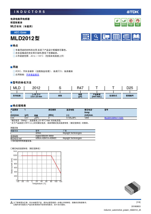
电源电路用电感器积层铁氧体MLD 系列(车载用)MLD2012型特点,实现了产品设计根据高可靠性。
,降低了泄漏磁束。
: –40 to +125°C(包括自我温度上升)用途、汽车多媒体(远程信息处理)、各类ECU 、各类模块应用指南:汽车信息娱乐型号的命名方法特点规格表*额定电流(Itemp ):温度最高上升40°C max.时的电流值。
*关于产品温度为 85°C 以上时的额定电流,请参照额定电流温度特性(额定值降低)的图表。
测量设备*有时使用同等测量设备。
○额定电流温度特性(额定值降低)MLD2012SR47TTD25系列名称L×W 尺寸类别电感产品高度包装形式管理编号2.0×1.25 mm(µH)(mm max.)产品厚度L 测定频率直流电阻额定电流*型号T Itemp(mm)max.(µH)容差(MHz)(Ω)(mA)max.0.550.47±20%20.120±30%1200MLD2012SR47TTD25测量项目型号厂商L4294AKeysight T echnologies 直流电阻Digital Milliohm Meter 额定电流 Isat4285A+42841A+42842CKeysight T echnologiesAEC-Q200L 频率特性测量设备*有时使用同等测量设备。
L 直流重叠特性测量设备*有时使用同等测量设备。
型号厂商4294AKeysight Technologies型号厂商4285A+42841A+42842C Keysight T echnologies形状与尺寸推荐焊盘布局推荐回流焊温度曲线图包装形式Carrier tape material:Polystyrene Cover tape material:Polystyrene温度范围、单个重量*工作温度范围包括自我温度上升。
3000设备入门指南说明书

[分类:受限制]Check Point版权声明©2020Check Point Software Technologies Ltd.保留所有权利。
本产品及相关文档受版权保护,并且凭限制其使用、复制、分发及反编译的许可进行分销。
未经Check Point的事先书面授权,不得对本产品或相关文档的任何部分,以任何形式或任何方式进行复制。
在本手册编制过程中已非常谨慎,但Check Point不对任何错误或疏漏承担责任。
本出版物及其中所述功能如有更改,恕不另行通知。
限制权利图注:政府的使用、复制或纰漏须符合DFARS252.227-7013和FAR52.227-19的“技术数据和计算机软件权利”一条中第(c)(1)(ii)款规定的限制。
商标:参考版权页以获取我们的商标清单。
参考第三方版权声明以获取相关版权和第三方许可的清单。
重要信息最新软件我们建议您安装最新版软件,以获得最新的完善功能、更好的稳定性、更高的安全级别,并防止发展中的新攻击入侵。
认证有关Check Point产品的第三方独立认证,请参见Check Point认证页面。
Check Point3000设备如需更多有关此版本的信息,请参见主页。
此文档的最新版本请打开网页浏览器中此文档的最新版本。
请下载此文档(PDF格式)的最新版本。
反馈Check Point一直在致力于完善其文档。
请发送您的意见给我们,以帮助我们不断改进。
修订历史目录安全和环保声明7合规信息9符合性声明9引言14欢迎14 3000设备概述14装运箱内容物15术语15将3000设备安装于机架16设备物理规格16设备通风口16配置3000设备18启动设备18可用软件映像18初始配置18创建网络对象18高级配置18连接至3000设备CLI19 3000设备硬件20前面板20后面板22在3100/3200设备中安装电源配适器固定夹22双冗余BIOS25更换和升级组件26恢复出厂默认设置27通过Gaia门户进行恢复27通过启动菜单恢复27通过Gaia Clish进行恢复28注册和支持29注册29支持29如何进阶?29安全和环保声明请在设置或使用设备前阅读以下警告。
A300Pro有源音箱 使用说明书
有源音箱A300Pro 使用说明书东莞普兰迪音响系统有限公司邮编: 523808 地址: 东莞松山湖高新技术产业开发区工业东路2号一区办公楼第六层服务热线: 400-810-5526OPT COAXAUXBASS TREBLE在操作使用前,请仔细阅读下述内容并务必遵守下列基本注意事项,请将此说明书妥善保管以备将来随时参阅。
1. 将音箱连接到音源设备之前,请关闭音箱的电源 开关,并务必保证音量旋钮为最小位置。
2. 请勿将电源线及信号线置于热源(如加热器、散 热器)附近,不要将其放置在可能被踩踏引起绊 倒或挤压的地方。
3. 连接音箱电源时请使用便于拔插的电源插座,当 准备长时间不使用音箱时,请关闭电源开关并将 电源线从插座拔下。
4. 为了避免雷击可能造成损坏,雷电期间请关闭音 箱电源并将电源线从插座断开。
5. 将电源线从墙上插座断开时,请抓住插头,勿拖 拉导线而致使导体受损。
6. 只能使用本机所规定的额定电压。
在本机上使用 比规定值高的电压会产生危险的并导致设备受损。
9. 请勿在可能有物体坠落或液体滴落,飞溅的地方 安装音箱。
在音箱的顶部请勿放置:* 任何形式的明火(如蜡烛),因为他们会产生 危险的并导致音箱受损。
* 内部装有液体的容器,因为它们可能会摔落, 且液体可能引起用户触电或损坏音箱。
10. 请将音箱放在一个稳固的位置,以防坠落造成 音箱损坏或人身伤害。
11. 请将音箱安装在通风良好并且干燥,远离直射 阳光、热源、振动、灰尘、潮湿或寒冷的地方。
为了确保音箱发挥最佳性能,请在音箱周围最 少留出20cm距离的间隙。
12. 请勿长时间持续在很高或不舒适的音量水平使 用音箱,否则可能对您的听力造成损伤。
13. 在搬动音箱之前,请关闭电源开关并将电源线 从插座断开。
7. 本机不含有任何用户可自行修理的零件,请勿打 开音箱试图拆卸内部零件或进行任何方式的改造。
若出现异常请立即停止使用,并及时联系专业维 修人员修理。
A3000使用详细说明(扫盲篇)

A3000使用详细说明(扫盲篇)一、设备概述1. 高清触摸屏,视觉效果出众。
2. 内置高性能处理器,运行速度快。
3. 丰富的应用软件,满足各种需求。
4. 支持WiFi和蓝牙连接,轻松实现设备互联。
5. 长续航能力,陪伴您度过美好时光。
二、设备部件及功能1. 正面屏幕显示区域:用于显示图像、文字和操作界面。
主页键:快速返回主界面。
返回键:返回上一级菜单或关闭当前应用。
2. 顶部电源键:开启/关闭设备。
音量键:调节音量大小。
3. 底部充电接口:连接充电器和数据线。
扬声器:播放音乐、视频和通话声音。
4. 侧面SIM卡槽:插入SIM卡,实现电话和上网功能。
内存卡槽:扩展存储空间,存放更多文件。
5. 背面摄像头:拍摄照片和视频。
闪光灯:在低光环境下提供照明。
三、基本操作1. 开启/关闭设备长按电源键,直至屏幕亮起或关闭。
在待机状态下,短按电源键可点亮或熄灭屏幕。
2. 解锁屏幕从屏幕底部向上滑动,进入解锁界面。
按照设定的解锁方式(如图案、密码或指纹)解锁屏幕。
3. 主界面导航在主界面,您可以左右滑动屏幕,查看不同页面的应用图标。
应用图标,即可打开相应应用。
4. 应用操作在应用内,根据提示进行操作。
使用返回键退出当前应用,或使用主页键快速返回主界面。
四、设置与管理1. 网络连接打开设置,选择“无线和网络”。
“WiFi”,开启WiFi并连接到您的家庭或公共网络。
若需要,您也可以通过“蓝牙”选项开启蓝牙进行设备配对。
2. 通知管理在设置中找到“通知”或“通知中心”。
选择您希望接收通知的应用,或关闭不必要的通知,以保持界面整洁。
3. 个性化设置在设置中找到“显示”或“外观”。
调整屏幕亮度、壁纸、字体大小等,让A3000更符合您的使用习惯。
4. 声音和振动在设置中找到“声音”或“音量”。
调整铃声、通知音、媒体音和闹钟音量,以及振动模式。
五、应用与功能1. 应用与安装打开应用商店,搜索您感兴趣的应用。
“安装”,等待应用并自动安装完成。
HSD123KPW1-A30 Preliminary Specification 1.0

The information contained in this document is the exclusive property of HannStar Display Corporation. It shall not be disclosed, distributed or reproduced in whole or in part withonStar Display Corporation.
H a n n Sta r Di s p l a y C o rp .
Document Title Document No. HSD123KPW1-A30 Preliminary Specification DC110-00**** Page No. Revision 5/23 1.0
2.0 ABSOLUTE MAXIMUM RATINGS
H a n n Sta r Di s p l a y C o rp .
Document Title Document No. HSD123KPW1-A30 Preliminary Specification DC110-00**** Page No. Revision 1/23 1.0
TO
:
深圳市迈瑞德电子有限公司
H a n n Sta r Di s p l a y C o rp .
Document Title Document No. HSD123KPW1-A30 Preliminary Specification DC110-00**** Page No. Revision 3/23 1.0
Contents
The information contained in this document is the exclusive property of HannStar Display Corporation. It shall not be disclosed, distributed or reproduced in whole or in part without written permission of HannStar Display Corporation.
A3000过程控制实验系统 使用说明和产品维护

第2页
广西大学 ASEA 培训中心
确认电缆与正确的端子相连接,否则,可能会发生爆裂、损坏等事 故。 始终应保证正负极性的正确,以防止爆裂、损坏等。
4 其他注意事项
!注意。当搬运产品时,请使用正确的升降工具以防止损伤,不要过 分颠簸,绝对禁止倾斜,甚至倾倒。
环境 周围环境温度 周围环境湿度. 储存温度 环境 海拔高度, 振动 5-+50℃ (不结冰) 90%RH 以下(不凝露) -20℃~~+65℃ 室内(无腐蚀性气体,可燃性气体,油雾和尘埃等等) 海拔 1000m 以下 59m/s 以下(JIS C 0040 标准)
第3页
广西大学 ASEA 培训中心
1.1 现场系统组成
A3000 高级过程控制实验系统独创现场系统 现场系统概念,而不是对 现场系统 象系统。现场系统包括了实验对象单元、供电系统、传感器、执 行器(包括变频器及移相调压器)、以及半模拟屏,从而组成了 一个只需接受外部标准控制信号的完整、独立的现场环境。它具 备如下特点: 1. 现场系统通过一个现场控制箱,集成供电系统、变频器、 移相调压器、以及现场继电器,所有驱动电力由现场系统提供。 它仅需通过标准接线端子接收标准控制信号即能完成所有实验功 能。从而实现了现场系统与控制系统完全独立的模块化设计。 2. 现场控制箱侧面是工业标准接线端子盒。这种标准信号接 口可以使现场系统与用户自行选定的 DCS 系统、PLC 系统、 DDC 系统方便连接,甚至用户自己用单片机组成的系统都可以 对现场系统进行控制。 3. 现场系统的设计另外的优势是保证动力线与控制线的电磁 干扰隔离。 4. 现场系统的设计保证了控制系统只需要直流低压就可以 了,使得系统设计更模块化,更安全、具有更大的扩展性。 该部分结构简图如图 2-1 所示:
多功能椅子3000系列产品说明书

ASSEMBLY INSTRUCTIONS FOR THE MULTICHAIR 3000 seriesmultichair 3000multichair 3200ASSEMBLY INSTRUCTIONSFigure 4 Figure 5 Figure 6 Figure 7OPERATING INSTRUCTIONSADDITIONAL SAFETY PRECAUTIONSFigure 9Figure 10Figure 8LIMITED WARRANTYA WARRANTY ACTIVATION Please read this warranty before operating or using your multiCHAIR. To activate the warranty on your multiCHAIR register it online or by phone. By operating or using the chair, you agree to the terms of this warranty.B WARRANTY: Nuprodx, Inc. warrants this product against defects in material and workmanship as follows: There is a 10-Day conditional money-back warranty. During this time period, the customer is permitted to try out the multiCHAIR, fully-clothed, keeping the chair in “like new” condition (NOTE: “Like new” condition, in terms of the multiCHAIR, is defined by Nuprodx, Inc. as no visible wear/usage/water marks for the multiCHAIR to be accepted and refunds issued when returned to Nuprodx, Inc.). If the customer decides that the multiCHAIR will not work for them, before the 10-Day period has passed and with the authorization of Nuprodx, the chair can be returned for a full refund minus a 10% restocking charge (NOTE: The customer is responsible for both in-bound and out-bound freight). After the initial 10-Day period has passed, there is a two-year limited warranty for all parts of the chair, with the exception of the seat and back cushions. The seat and back cushions carry a one year limited warranty. The warranty does not cover normal “wear and tear” from everday use of the product and custom parts/custom cushions are also excluded from the warranty and cannot be returned for a refund under any circumstances. Please see section E WARRANTY LIMITA-TION AND EXCLUSIONS for more info on warranty exclusions.C The warranty period begins on the date you receive the chair. For warranty service, please contact Nuprodx, Inc. no later than one month following the applicable warranty term. The chair will be repaired or replaced at the discretion of Nuprodx, Inc. with no charges to you for parts and labor, provided you have proof of purchase and of purchase date.D DISCLAIMER: Except for the above warranty, and the acknowledgement by Nuprodx, Inc. that the chair, as manu-factured by it, is fit for the general purpose for which most persons acquire a chair of its kind, Nuprodx, Inc. provides that you accept the chair as is, without warranties, either express or implied. Nuprodx, Inc. makes no warranty of fit-ness for your particular purpose and no warranty of merchantability beyond that already stated. No warranties extend beyond the duration of the express warranty stated above.E WARRANTY LIMITATIONS AND EXCLUSIONS: The only obligation of Nuprodx, Inc. is to provide the purchaser with free repair and replacement as described above. This exclusive warranty remedy will not have failed as long as Nuprodx, Inc. is willing and able to repair or replace as described, but if this remedy should be held to have failed, the only remaining warranty obligation of Nuprodx, Inc. shall be to refund the acts beyond the control of Nuprodx, Inc. The warranty does not cover normal “wear and tear” from everday use of the product. Custom parts/custom cushions are not covered under the warranty.F This warranty gives you specific legal rights, and you may have other rights that may vary from state to state.G This warranty does not apply to problems arising from normal wear, improper operation, improper maintenance, improper storage or similar disclaimer of implied warranties, and some do not allow limitations on how long an implied warranty may last. Some do not allow exclusion or limitation of incidental or consequential damages. So the above limitations or exclusions may not apply to you.H RETURN INSTRUCTIONS In the event that you need to return the Nuprodx multiCHAIR, please follow the instruc-tions below:1) Review the information contained in your warranty to see if this applies to you2) Obtain a Return Authorization # from Nuprodx, Inc.3) Re-package the entire chair and its contents in the original packaging and ship to the following address:。
Dwyer A3000 Series 压力仪 切换产品介绍说明书

VISIT OUR WEBSITES: • • .auSeries A3000Photohelic ®Pressure Switch/Gages3-in-One Indicating Gage, Lo-Limit and Hi-Limit ControlSPECIFICATIONSGAGE SPECIFICATIONSService: Air and non-combustible, compatible gases.Wetted Materials: Consult factory.Accuracy: ±2% of full scale at 70°F (21.1°C). ±3% on -0 and ±4% on -00models.Pressure Limits:-20˝ Hg. to 25 psig (-0.677 to 1.72 bar). MP option; 35 psig (2.41 bar), HP option; 80 psig (5.52 bar). A36003S – 36010S; 150 psig (10.34bar). A36020S and higher; 1.2 x full scale pressure.Temperature Limits: 20 to 120°F (-6.67 to 48.9°C). Low temperature option available.Process Connections:1/8˝ female NPT.Size:4˝ (101.6 mm) dial face, 5˝ (127 mm) O.D. x 8-1/4˝ (209.55 mm).Weight:4 lb (1.81 kg).SWITCH SPECIFICATIONSSwitch Type: Each setpoint has 2 form C relays (DPDT).Repeatability: ±1% of full scale.Electrical Rating:10A @ 28 VDC, 10A @ 120, 240 VAC.Electrical Connections: Screw terminals. Use 167°F (75°C) copper conductors only.Power Requirements: 120 VAC, 50/60 Hz; 240 VAC & 24 VAC power optional.Mounting Orientation: Diaphragm in vertical position. Consult factory for other position orientations.Set Point Adjustment: Adjustable knobs on face.Agency Approvals:UL, CSA, CE. Optional-EXPL explosion-proof enclosure does not possess any agency approvals.OPTIONSSingle contact,right set point, for actuation on increasing or decreasing pressure.OEM Model,less relay and transformer components and housing but including infrared diodes and phototransistor(s), light shutter and set pointer(s). For single or double contact.Remote-Mounted Relay,relay pack may be mounted remotely from gage.Standard length is 5 ft. For other lengths, specify cable length required.Tamper-proof knobs,low temperature option, special scales, voltages and other features and modifications are available.Special Housings available include Weatherproof (NEMA 4) and Explosion-proof (NEMA 7 CD, 9 EFG; NEC Class I, DIV. 1 & 2, Groups C, D, Class II, Div.1 & 2, Groups E, F, G, Class III.) Contact Customer Service for detailed dimension drawings.Photohelic ®Switch/Gages func tion as versatile, highly repeatable pressure switc hes c ombined with a prec ise pressure gage employing the time-proven Magnehelic ®gage design. The Photohelic ®gage measures and controls positive,negative or differential pressures of air and compatible gases. Standard models are rated to 25 psig (1.7 bar) with options to 35 (2.4) or 80 (5.5 bar) psig. Single pressure 36000S models measure to 6000 psig (413 bar) with a 9000 psig (620 bar) rating.Two phototransistor actuated, DPDT relays are included for low/high limit control.Easy to adjust setpoint indicators are controlled by knobs located on the gage face.Individual setpoint deadband is one pointer width — less than 1% of full sc ale.Setpoints can be interlocked to provide variable deadband — ideal for control of fans,dampers, etc. Gage reading is continuous and unaffected by switch operation, even during loss of electrical power. Choose from full scale pressure ranges from a low 0-.25" (0-6 mm) w.c. up to 30 psi (21 bar); single positive pressure to 6000 psig (413 bar). Photohelic Sensing - How It WorksIn typical applications, these Dwyer switch/gages control between high and low pressure set points. When pressure changes, reaching either set point pressure, the infrared light to the limiting phototransistor is cut off by the helix-driven light shutter. The resulting phototransistor signal is electronically amplified to actuate its DPDT slave relay and switching occurs. Dead band between make and break is 1% of full scale or less — just enough to assure positive, chatter-free operation.Relay - Transformer FeaturesA plastic housing protects all electronic components. Solid-state and integrated circuit electronics are on glass-epoxy printed circuit boards and self-extinguishing terminal boards.APPLICATIONS - PHOTOHELIC ®SWITCH/GAGESIn both series of pressure switch/gages, you get the convenience of a visual indication plus high-low limit switching. For both OEM and in-plant applications,the Photohelic ®switch/gage is used to control pressures in air conditioning systems, clean rooms, fluidic and pneumatic control systems, materials handling equipment, alarm or control fume exhaust systems, control pressure in air structures, and monitor respiratory and blood pressures.Standard ModelTwo phototransistor-actuated circuits and two DPDT relays permit both high and low alarms or limit controls. Relays are de-energized when gage pointer is to the left of respective set points; relays are energized as pointer passes to the right of set points. Loss of electrical power or loss of pressure provide “fail safe” protection.High and Low Latching CircuitsDwyer Photohelic ®switch/gages can be wired for high-latching, low-latching or combination high-low latching circuits. That is, the equipment will hold in these respective positions once activated and until manually reset. This can be particularly useful for alarm and signal applications where control is accomplished by another Photohelic ®switch/gage or other means. Complete wiring and operational instructions are included. Where manual reset is required a dry circuit push button such as Dwyer Part A-601 should be used.CALL TO ORDER: U.S. Phone 219 879-8000 • U.K. Phone (+44) (0)1494-461707 • Australia Phone (+61) (0) 2 4272 205521Bezel and front cover (with set point knobs and zero adjustment screw)removed to expose Photohelic ®gage set point mechanism. Cover is clear polycarbonate plastic.Gage pointer and light shutter are mounted on helix and balancingcounterweight. Shutter passes through slot in optical limit switch to exposephototransistors to integral infrared light source or mask them depending on applied pressure.Light shield effectively protectsphototransistors from strong outside light sources yet allows free pointermovement. It also gives interior a clean “finished” look.Optical limit switches are used for reliability and long service life. Attached directly to set pointers, they areindividually aligned to assure precise switching accuracy.Semi-Flexible drive shaft connects to set point knobs.Zero adjustment screw connects to screw in cover to adjust zero pressure reading.Plastic enclosure protects electronic components and electrical connections.Polycarbonate connection or terminal board is self-extinguishing.Glass-epoxy printed circuit boards for durability and performance.Load relays are DPDT with latching feature for maximum application versatility.Electronics are designed to operate on 50/60 Hz, 120 volt current with 10% over or under voltage. Special units for other voltages are available.Switch set pointers show switch settings at all times.Spring loaded friction clutch prevents operator damage of set point mechanism.Check these features for dependable controlModels and Ranges - Series A3000 Photohelic ®Switch/GagesNote:Special models can be built to OEM customers' specifications with scales reading in special pressure units like ounces per square inch,inches of mercury, etc. Square Root Scales reading in FPM or SCFM are also available. Custom logos and special graduations can also be included.Contact factory for minimum quantities and pricing.OPTIONS & ACCESSORIES - Add options as a suffix. Example: A3001-LT -SRH, Single Relay Activates on Increase .N/C -SRL,Single Relay Activates on Decrease N/C -OLS, OEM model . . . . . . . . . . . . . . . . . . .N/C -RMR, Remote mounted relay . . . . .add 50.50-TAMP , Tamper proof knobs . . . . . . .add 10.50-MP , Medium pressure . . . . . . . . . .add $37.50-HP , High pressure . . . . . . . . . . . . .add 107.00-LT, Low temperature (-20°F) . . . . . .add 10.00A-298,Flat Flush Mounting Bracket . . . .26.75A-601,Manual reset switch net . . . . . . . .34.50。
RFL-A3000D~6000D 光纤输出半导体激光器英文说明书
版本号密级内部A0会签阶段标记SRFL-A3000D~6000D光纤输出半导体激光器英文说明书RFL-A3000D~6000D·JS02部门半导体激光器技术研究部编写曾诚20201222校对李辉20201227审核刘超20201230标审李其军20201231批准胡慧璇20201231无锡锐科光纤激光技术有限责任公司王志源黄文娟旧底图登记号/底图登记号/Fiber Delivered Direct Diode Lasers User GuideRFL-A3000D~6000TABLE OF CONTENTS1Safety Information (3)1.1Symbols Used in this User Guide (3)1.2Laser Classification (3)1.3Optical Safety (4)1.4Electrical Safety (4)1.5Other Safety Rules (4)2Product Description (5)2.1Features (5)2.2Package Contents (5)2.3Unpacking and Inspection (5)2.4Operation Environment (6)2.5Matters Need Attention (6)2.6Specifications (7)3Installation (8)3.1Dimensions (8)3.2Installation Procedure (9)3.3Cooling Requirements (11)4Using the Product (12)4.1Front Panel (12)4.2Rear Panel (14)4.3Power Connection (15)4.4Interface Definitions (17)4.5Work Patterns and Control Modes (19)4.6Selection of Control Mode (19)4.7Hyperterminal Mode (20)4.8RS-232Mode (22)4.9AD Mode (23)5Alarms and Solutions (25)5.1Fault Records and Occurrences (25)5.2Alarm Solutions (26)6Warranty Return and Maintenance (27)6.1General Warranty (27)6.2Limitations of Warranty (27)6.3Service and Repair (28)1Safety InformationThank you for choosing Raycus fiber laser.This User Guide provides important,safety, operation,warranty and other information.Please read it carefully before you use this product.In order to ensure safe operation and optimal performance of the product,please follow the warnings,cautions,operating procedures and other instructions accordingly.1.1Symbols Used in this User Guide◆Refers to a potential hazard that may lead to a personal injury ordeath.◆Refers to potential a hazard that may lead to a minor personal injuryor product damage.1.2Laser ClassificationThis series of lasers are classified as a high power Class4laser instrument according to the European Community standards EN60825-1,clause9.This product emits invisible laser radiation at or around a wavelength of915nm,and the total light power radiated from the optical output is greater than3000W~6000W(depending on model).Direct or indirect exposure of this level of light intensity may cause damage to the eyes or skin.Despite the radiation being invisible,the beam may cause irreversible damage to the retina and/or cornea.Appropriate and approved laser safety eyewear must be worn all the time while the laser is operating.◆You must use appropriate laser safety eyewear when this device isoperating.The laser safety eyewear is selected according to therange of wavelengths emitted from this product.The end user mustensure that the laser safety eyewear being used protects against lightemitted by the device over its entire range of wavelengths.Pleaseverify that the personal protective equipment(e.g.enclosures,viewing windows or viewports,eyewear,etc.)being utilized isadequate for the output power and wavelength ranges listed on theproduct.1.3Optical SafetyAny dust on the end of the collimator assembly can burn the lens and damage the laser.◆If the output of the device is delivered through a lens with ananti-reflection coating,make sure that the lens is of good qualityand clean.1.4Electrical SafetyMake sure your product is grounded through the PE line of the AC power cord.The grounding must be firm and reliable.◆Any interruption from the protective earth will electrify theenclosure,which may result in personal injury.Make sure that the correct voltage of the AC power source is used.◆Failure to connect the correct voltage could damage the product.1.5Other Safety Rulesa)Never look directly into the laser output port when power is supplied to the laser.b)Avoid using the laser in a dim or darkened environment.c)If this device is used in a manner not specified in this document,the protection provided bythe device may be impaired and the warranty will be voided.d)Do not remove the covers of the laser,or the warranty will be voided.All maintenance mustbe performed in Raycus or by qualified Raycus personnel.2Product Description2.1FeaturesCompared with traditional lasers,Raycus CW fiber diode laser has higher efficiency electric-optical conversion,lower power consumption.The fiber laser is compact and ready to use.Because of its flexible form,it can be easily integrated with the system equipment.Main Features:a)Flexible output optical cableb)High reliability and long service lifec)Maintenance free operationd)High photoelectric conversion efficiencye)Convenient control interfacef)High frequency modulationMain Applications:a)Laser-quenchingb)Laser-claddingc)Laser-weldingd)3D-printinge)Scientific research2.2Package ContentsPlease refer to the packing list accompanying the shipment to check actual items included.2.3Unpacking and InspectionRaycus ensure that the laser do get adequate protection by special designed packaging material and box during the transit.Even so,In order to prevent the unpredictable component damage,users need to scrutinize the packing box is right before unpacking it whether or not cracking,abrasion,dampened and other phenomena.if there is any abnormity in the box body, Please contact us,we will correct it immediately.On unwrapping the box,Please check that packing lists and physical goods are the same.If you have any questions,feel free to contact any of us at any time.When taking the laser out of the box,Avoiding knock against and violent vibration on the laser.When taking optical fiber and output head,In particular,It is not possible to bend,twist and pull optical cable,At the same time should avoid output head suffering the blows and vibrations.The fiber optic cable and output head is precise optic instrument,anyvibration or impact to the output head,and twist or excessive bend to thecable will damage the instrument.2.4Operation EnvironmentThe basic operation conditions are listed in the table below:Table1Basic Operation Conditions for the LaserProduct Model RFL-A3000D RFL-A4000D RFL-A6000DPower Source TN-S,380±38VAC,50/60HzPower Capacity8kW10kW15kW Installation Environment Flat with no vibration and shockAmbient Temperature10~40℃Relative Humidity<70%a)Ensure reliable grounded before using the laser.b)The laser output is connected to the output cable.Please check the laser output carefully toprevent dust or other e special paper when cleaning the laser output lens.c)If the laser is used in accordance without the method specified in this manual,the laser maybe in abnormal working state and cause damage.d)It is strictly forbidden to install the laser output when the laser is in operation.e)Do not look directly into the laser output.Be sure to wear protective glasses when operatingthe laser.2.5Matters Need Attentiona)Before supplying the power to the device,make sure that the voltage of the AC powersource is380V.Failure to connect power source correctly will damage the device.b)Failure to follow the instructions may cause malfunction and damage to the device,suchdamage is not covered by warranty.c)It is very important to ensure the cleanness of the calibrated laser output head,otherwise itwill cause irreparable damage to the laser.d)Please inspect the output head carefully for dust or other e appropriatelens paper to clean it if necessary.Do not touch the output lens at any time;as well as remember to cap the output head when it is not in use,and make sure the cap is clean.e)Failure to follow the specified instructions may result in the loss of laser power,and suchloss will not be covered by the warranty.2.6SpecificationsTable2P roperties of P roductsOptical ParametersModel RFL-A3000D RFL-A4000D RFL-A6000D Nominal Output Power(W)300040006000 Operation Modes CW/ModulatedPolarization Orientation RandomOutput Power Tunability(%)10~100Emission Wavelength(nm)915±10Output Power Instability(%)≤3Modulation Frequency(Hz)50~5kPilot Light Power(mW)0.25~1Output Cables ParametersOutput Header Type QBH HQBHFiber Core Diameter(μm)600800Minimum Bending Diameters≥400≥500Half Angle of beam divergence(rad)≤0.22Delivery Cable Length(m)20(Customizable)Electrical ParameterPower Supply AC380V±38,50/60Hz,TN-SControl Mode Hyper Terminal/RS-232/ADOther ParametersDimensions(W×H×D)(mm)650×950×980890×1010×952 Weight(kg)<150<300 Operating Ambient Temperature(℃)10~40Humidity(%)<70Storage Temperature(℃)-10~60Cooling Method Water Cooling3Installation3.1DimensionsFigure1shows dimensions of products:Figure1a)3000W Overall Dimension(unit:mm)Figure1b)4000W,6000W Overall Dimension(unit:mm)3.2Installation Procedurea)Place the product in an appropriate position,immobilize it if necessary.b)Check if the power supply has the correct voltage(AC380±38V,50/60Hz,TN-S),and theearth line is connected,make sure it is firm and reliable.c)Connect the power cable and control cable to the product when power supply is OFF.d)Insert the water pipes into the inlet and outlet;e)Check the output head and clean it if necessary.This procedure must be performed byRaycus personnel or person authorized by Raycus.Make sure the environment is clean,or the output cable may be contaminated.f)Prevent the delivery cable from treading,pinching or excessive bending during installation.g)In the installation of laser output cable and output head process,please make sure that thesurrounding environment is clean,otherwise it may pollute the output head(do not use fans to avoid dust).h)The client can use four hooks or rollers at the top or bottom of the product to move theproduct,as shown in figure2.Examine each hooks and rollers for damage before use.Figure2a)Hooks at the Top of the LaserFigure2b)Rollers at the Top of the LaserAll the cables can only be connected when power supply is OFF.Hot plug may damage the laser.◆The laser output optical cable should be kept as natural as possible and not bedistorted.◆The too small bending radius of the output fiber cable will damage the laser.◆Make sure the aperture and the cavity of the processing head is clean.◆Prevent it from contamination;Or the aperture will be contaminated whencapped.3.3Cooling RequirementsTable3Cooling RequirementsParameters unit RFL-A3000D RFL-A4000D RFL-A6000D Cooling Capability Capability kW≥6(2.4HP)≥10(4HP)≥14(5.6HP)Minimum Flow L/min254060 Maximum Input Pressure Bar4~6Pagoda-Shape Connectors mm Connect InnerDiameterΦ19Water pipeOutside Screw3/4,Hose ConnectionΦ25Water Chiller Categories/dual-temperature controlThe water temperature setting of cooling system:a)summer(Ambient temperature is higher than30℃)25±0.5℃.b)winter(Ambient humidity temperature is lower than30℃)22±0.5℃.Coolant requirements:a)The cooling water is pure water.It is recommended to use pure drinking water;b)In order to prevent mould growing that may lead to pipe blockage,we recommend toadd alcohol about10%of the total volume.c)When the ambient temperature ranging between-10℃and0℃,user need to addalcohol about30%of the total volume,change alcohol every two years.d)When the ambient temperature below-10℃,user must use dual-cooling water chiller,and ensure continuity of work.Other requirements for chiller:a)When starting the cooling system for the first time,check the entire water system andthe joint for water leakage.The external water pipe must be installed and connected according to the inlet(IN)and outlet(OUT)by the laser.Otherwise,the laser may not work properly.b)If you will not use the laser for a long time,water must be emptied from the product,and then both the inlet and outlet must be blocked with the nuts we provide.Failure to do so may lead to permanent equipment damage.c)When the customer is empting the cooling water of the laser water-cooling system,please use compressed gas with pressure less than0.5mpa,otherwise it will cause irreparable damage to the chiller.◆Please set the water temperature in strictly accordance with the requirementsabove.Too low temperature may lead to condensation on the laser module andthe output cable.This can cause serious damage to the equipment.◆Make sure that the water temperature reaches the set point and the coolingsystem is working well before you start the laser.(summer:25±0.5℃;winter:22±0.5℃)4Using the Product4.1Front PanelFigure3shows the front panel of the product:Figure3Front Panela)REM/OFF/ON:Key switch,the power switch of the laser.Insert the key and turn the key clockwise to the'ON'position or counterclockwise to'REM'position will power on the laser.Then the laser will enter a control mode depending on your previous setup on the'INTERFACE'.You can refer to4.6Control Mode for more details.b)POWER:Power Indicator,indicates that the power is switched on,when the green LED illumines.c)LASER:Laser emission indicator,RED,illuminates when laser emission is on.d)ALARM:Alarm indicator,YELLOW,indicates an error condition.e)STOP:Pressing this button can shut down the laser,then Rotating this button to release.Use the key to power up the laser to get back.f)Indicator Light:Turn the key clockwise to the'ON'or'REM'position,the green indicator light is on;The red indicator light is on,when the laser emit laser;The yellow indicator light is on and the alarm goes off.4.2Rear PanelFigure4Rear PanelFigure4shows the rear panel of the product:a)AC INPUT:The socket for supply source input that can only be mated with the plug on the power cord we provided.The socket is equipped with protective cover and latch, Cover the power input interface with protective cover and secure it with latch when not using the product for a long time.b)INTERFACE:This interface provides all control signals,including RS232 communication,laser switch control,laser remote control mode selection,analog control,modulation signal,Interlock interface and so on.The socket is equipped with protective cover and latch,Cover the power input socket with protective cover and secure it with latch when not using the product for a long time.c)WATER:Pagoda-Shape Connectors,water inlet and outletare used for cooling water inflow and outflow.The laser side panel circuit breaker is shown in figure5,It is the main power switch of the laser.Figure5Side Panel4.3Power Connection◆Before connecting the product to AC supply source,you must check up that theAC supply you will apply is in accordance with the specifications provided.◆Failure to connect power source correctly will damage the device.Pleasecarefully inspected before energize the laser to make sure the connections arecorrectAs the figure6shows,the power cord,provided by the company:Figure6Power CordOne end of the power cord is a plug,insert it into the socket'AC INPUT'on the rear panel. Notice that the plug is wrong-side preventing.After inserting it,lock it with the lever,as shown in figure7.1.Protective Cap;2.Lock Catch;3.Plug;4.SocketFigure7Locked Power Outlet PortThe lasers’power line consists of five lines,L1,L2,L3,N and PE,Connected to the380VAC.Before the laser is powered up,Users must connect as shown in table4.Table4Power Connection InstructionsLabel Pin Number Color DefinitionL11Red Phase Line1L23Yellow Phase Line2L35Blue Phase Line3N4Black Neutral linePE GND Yellow Green Protective Ground WireThe length of the The lasers’power line provided by us is8m.4.4Interface DefinitionsAll control signal centers on rear panel’s port‘INTERFACE’.Figure8shows the control signal line provided by us.Figure8Control Signal LineWhen you want to use the product,please insert control signal cables provided by us in rear panel’s port‘INTERFACE’,and lock it with the lever,as shown in figure9.Figure 9Locked Power Outlet Port1.Protective Cap;2.Lock Catch;3.Plug;4.SocketThe following table details each pin in the ‘INTERFACE’port.Table 5The Definition of Control Signal Cables Name Pin Label Color DefinitionRemark CONTROL 6LAS_C White Enable signal for emitting laser light,high level is 24V.The laser is in ready state of emitting laser.This port have the same function as the button ‘LASER’on the front panel.Both cannot be used together,otherwise laser doesn't work on the primary.While using this signal line,the button ‘LASER’in a closed state.All reference ground of ‘CONTROL’cables are ‘EGND’7AD/RS Green Control mode selection.Turn the key switch to the "REM"position,this port is powered and in high level,the laser enter AD mode,Otherwise,it goes to RS232mode.\PE \Protecting earthing,Connect the cable shielding layer with protecting earthing.AD 220-10V Red Analog voltage signal.Adjust the laser power by setting the input analog voltage.Exclusive analog voltage input cable 25AGND Black Analog voltage ground \PE \Protecting earthing,Connect the cable shielding layer with protecting earthingMODULATION 36MOD+Red 24V modulation signal input port\37MOD-Black\PE \Protecting earthing,Connect the cable shielding layer with protecting earthing.INTERLOCK 38ITL_A Red Remote protection.Port ‘ITL_A’and‘ITL_B’must be connected during the laser working.\39ITL_B Black RS-23240RX Red Connect upper computer RXRS232or HyperTerminal Control 41TX Yellow Connect upper computer TX42GND Blue Serial port line ground\PE \Protecting earthing,Connect the cable Please check the level of control signal to ensure it meets the requirements.Both fluctuated and overloaded voltage may damage the laser4.5Work Patterns and Control ModesThere are two work patterns for the laser:CW(continuous wave)and pulse mode.In CW mode,the laser emits continuously.As for pulse mode,The output of the laser is a pulsed laser,transform the waveform by setting frequency,duty ratio and the percentage of power.There are three control modes to choose from,namely hyperterminal mode,RS-232mode and AD mod.Hyperterminal mod is fundamental mode ,Both RS-232mode and AD mode are external control mode.As for hyperterminal mode and RS-232mode,All parameters can be set up in two work patterns:CW and pulse mode.In AD mod,output power is under the control of input analog voltage signal and enable signal for emitting laser light is controlled by modulating signal.The sensors allow user to monitor the state of the laser.The laser shut off automatically once an exception occurs,and sends error messages by RS-232.4.6Selection of Control ModeFigure 10shows the selection of control mode.Figure10The Procedure of Mode SelectionTo select hyperterminal mode,user must turn the key switch to the“ON”position.If user want to enter external control mode(RS-232mode and AD mode),need to turn the key switch to the“REM”position.In addition,the wipers default to select RS-232mode while the key switch is turned to the“REM”position.If the laser is to enter AD mode,user must apply24V high level to port‘AD/RS’in advance.4.7Precautions before power up the laserBefore power up the laser,Check if the laser’s condition meets the following requirements:a)Power line and control line is connected properly and voltage meets the productrequirements.b)Enable signal button on the front panel is in the position of release and‘INTERFACE’port’s Pin6‘LAS_C’on the rear panel is low level.c)‘Interlock’is in good condition.d)Complete the water cooling system,The chiller start work and water is at appropriateoperating temperature,then ensure there is no leakage phenomenon in the whole watersystem.4.8Hyperterminal ModeHyperterminal mode is a tool for Windows communications,so the laser need to be controlled by windows PC.In this mod,user can set up all parameters and view fault records.4.8.1Wiring in Hyperterminal ModeFigure11Wiring in Hyperterminal Mode4.8.2The Setting Process of Hyperterminal ModeYou can follow these steps to set up hyperterminal mode:a)Do the following in windows:Click‘Start’-‘Accessory’-‘Communication’-‘hyperterminalmode’.b)A dialog then pops up recommend setting‘Hyper Terminal’as default‘telnet’program,Click‘Yes’.c)You can name‘New Connection’whatever you want,then Click‘OK’.d)Choose port number that the transmission cable connected(COM1or COM2or COM3),then Click‘OK’.e)Set up the COM port and parameters.Baud Rate9600,Data length8,Parity check-off,Stopbit1,Data flow-off,then Click‘OK’.The setup of Hyperterminal Mode is now complete.4.8.3Operations in Hyperterminal Mode.a)Turn the key switch to‘ON’,The laser is electrified,Green indicator‘POWER’is on.b)Waiting for10s until the internal main control board circuit initialization is completed.c)Enter user interface through following the prompts in hyperterminal.d)Users according to need to choose work pattern and set the related parameters.e)Trigger enable signal for emitting laser light(press enable signal button on the front panelor pin6‘LAS_C’on the rear panel is high level)Note:click‘3’or‘4’on pattern user interface,then enter external control mode.In this mode,the laser is set in the same way as CW mode,just adds a pre-condition that external24V modulating signal,through‘MODULATION’cable.4.9RS-232ModeRS232belongs to external control mode.In this mode,the laser is controlled by PC through communication protocol,user can set operating parameter and switch optical shutter.In addition, provides external MOD signal to control enable signal for emitting laser light.4.9.1Wiring in RS-232ModeFigure12Wiring in RS-232Mode4.9.2Communication ProtocolThe communication protocol is as follows in this table.Table 6Communication Protocol Based on RS-232Mode CodeDefinition Sample 1B4F0DOpen optical shutter TXD:1B4F0D RXD:54530D 1B530DClose optical shutter TXD:1B530D RXD:54530D 1B4350XX0D Set as CW mode,XX represent power percentage,range from 0to 100,Hexadecimal notation.TXD:1B4350320D RXD:54530D In CW mode,power percentage is 50%.1B46XXXX44##50&&0D Set as Pulse mode,XXXX represent frequency (50~5000),##represent duty cycle (0~100),&&represent the percentage of power (0~100),are Hexadecimal notation.TXD:1B461388443C50500D RXD:54530D In the pulse mode,Repetition frequency:5kHz Duty ratio:60%Power percentage:80%54530D Receive code echo reply message \5445310D Error 1\5445320D Error 2\5445330D Error 3\5445340D Error 4\5445350D Error 5\5445360D Error 6\5445370D Error 7\5445380D Error 8\5445390D Error 9\5445400DError 10\4.9.3RS232Mode Operation Procedure a)Turn the key switch to ‘REM’,The laser is electrified,Green indicator ‘POWER’is on.b)Wait 10s,The internal circuit initialization phase is complete.c)Send Open optical shutter signal with code of 1B4F0D.d)Set the parameters follow the instructions in the table 6.e)External modulating signal is 24V through ‘MODULATION’cable.4.10AD ModeAD mode belongs to the external control mode too.In AD mode,output power is under direct control of analog voltage signal.4.10.1Wiring in AD ModeFigure13Wiring in AD Mode4.10.2AD Mode Operation Procedurea)When PIN7and PIN9of the DB25control interface is applied to24V,the laser enters theexternal AD mode.b)Turn the key switch to‘REM’,Green indicator‘POWER’is on.c)Waiting for10s until the internal main control board circuit initialization is completed.d)The power of the laser is controlled by the voltage obtained by PIN22and PIN25of theDB25interface connector.e)The external MOD interface provides modulating signal for the laser.f)Enable the laser to emit laser light through one of the following ways:1)PIN6and PIN9of the DB25control interface is applied to24V.–laser enable signal.2)Press‘Laser’button on the front panel.–laser enable signal.◆Please Make sure that analog voltage signals never exceed10v,it maydamage the laser.4.10.3Pilot Light to ControlIn hyperterminal and AD mode,Turn the key switch to the‘REM’or‘ON’position and power up the laser,‘POWER’green indicator light is on and the laser emit pilot light.‘LASER’button on the front panel is pressed or external control signal‘LAS_C’is high level,pilot light is off.In RS-232mode,when open optical shutter,Pilot light is off;when close optical shutter, Pilot light is on.◆The pilot light and laser beam cannot exist simultaneously.If there is no pilotlight,please check if‘LASER’button on the front panel is pressed,externalcontrol signal‘LAS_C’is high level,or optical shutter is opened.5Alarms and Solutions5.1Fault Records and OccurrencesConnect computer and open hyperterminal interface,each time the laser is started and pass self-inspection,will display fault records,as shown in figure23.Figure14Fault Records in Hyperterminal InterfaceWhen inner temperature,output power,Power supply is abnormal and ‘INTERLOCK’is off,the laser will break down.Hyperterminal interface shows any defects at run time,meanwhile,the ALARM light (yellow)on the front panel of the laser will light up,the laser will stop emitting and lock.Before repower the laser,can’t unlock the laser.5.2Alarm SolutionsThe instructions and solutions of alarms are as follows:Table 7Instructions and Solutions for Alarms of Laser Alarm name Alarm instructions and solutionsFailure 1Instruction:Temperature alarm of the laser.There are 4sensor in the laser detects an abnormal temperature inside the laser.A high-temperature /low-temperature error occurs when the temperature at the monitoring point exceeds the set upper /lower limit.Solution:High temperature alarm,please check if the water-cooling system is normally working,the water temperature and connection is correct.When the water cooling system works normally and the water temperature drops below 30°C,restart the laser.If the alarm continues,please contact Raycus.Low temperature alarm,please check if the actual water temperature of the water is too low.In addition,a low ambient temperature may also cause a low temperature alarm when the laser is cold.Please wait until the water temperature of the water rises above 10°C.If the alarm continues,please contact Raycus.If T4sensor send s out low temperature alarm,one possibility is that one pair of contacts ‘Interlock pins’is not connected reliably.Please verify contacts stay in good contact.Failure 2Allowance fault code,no meaning.Failure 3Allowance fault code,no meaning.Failure 4Instruction:The laser will get this error when it does not emit with correct settings.Power error occurs only when the laser is emitting.Solution:Restart the laser,if this error continues to occur,please contact Raycus.Failure 5Instruction:Occurs when the InterLock is disconnected.Solution:Short-circuit the InterLock pins (please consult table 5,Connect ‘ITL_A’and ‘ITL_B’)and restart the laser to try.If this error continues to occur,please contact Raycus.Failure 6Allowance fault code,no meaning.Failure 7Allowance fault code,no meaning.Failure 8Instruction:ACDC1Error,failure of the laser power supply or sudden power failure of the power supply system may cause an alarm.Solution:Check if the input AC voltage is normal.Restart the laser,if this error continues to。
RFL-A3000D~6000D光纤输出半导体激光器中文说明书

版本号密级内部A0会签阶段标记S RFL-A3000D~6000D光纤输出半导体激光器中文说明书RFL-A3000D~6000D·JS01部门半导体激光器技术研究部编写曾诚20201222校对李辉20201225审核刘超20201228标审李其军20201230批准胡慧璇20201230无锡锐科光纤激光技术有限责任公司王志源黄文娟旧底图登记号/底图登记号武汉锐科RFL-A3000D~6000D 光纤输出半导体激光器使用说明书控武汉锐科目录武汉锐科1安全信息 (3)1.1安全标识 (3)1.2激光安全等级 (3)1.3光学安全 (4)1.4电学安全 (4)1.5其他安全注意事项 (4)2产品介绍 (5)2.1产品特性 (5)2.2装箱清单 (5)2.3开箱及检查 (5)2.4运行环境 (6)2.5注意事项 (6)2.6产品性能 (7)3安装说明 (8)3.1安装尺寸图 (8)3.2安装注意事项 (9)3.3冷却系统安装与要求 (11)4产品的使用 (12)4.1前面板 (12)4.2后面板 (13)4.3电源连接 (14)4.4控制接口定义 (16)4.5激光器工作模式及控制方式 (18)4.6控制模式的设置 (18)4.7激光器启动操作流程 (19)4.8超级终端模式 (19)4.9RS-232模式 (20)4.10AD模式 (22)4.11红光控制 (23)5常见故障及处理措施 (23)5.1故障记录及故障的发生 (23)5.2故障处理.......................................................................................................................246质保及返修、退货流程.. (25)6.1一般保修.......................................................................................................................256.2保修的限定性...............................................................................................................256.3技术支持及产品维修 (26)武汉锐科1安全信息感谢您选择无锡锐科光纤输出半导体激光器,本使用说明书为您提供了重要的安全、操作、维护及其它方面的信息。
- 1、下载文档前请自行甄别文档内容的完整性,平台不提供额外的编辑、内容补充、找答案等附加服务。
- 2、"仅部分预览"的文档,不可在线预览部分如存在完整性等问题,可反馈申请退款(可完整预览的文档不适用该条件!)。
- 3、如文档侵犯您的权益,请联系客服反馈,我们会尽快为您处理(人工客服工作时间:9:00-18:30)。
产品型号:A300产品名称:智能二代证识别终端(一体机)
特征
描述
备注
机板配置
主要功能:
-定位于“宽屏智能手机”;
- Windows mobile 6.5操作系统;
- 3.5寸LCD,四层钢化玻璃纯屏TP;
- GPS定位导航;
- 500万高清摄像(自动对焦)
-二代证识别;
二代身份证模块
公安部标准模块
外置存储卡
T-Flash
蓝牙
支持
喇叭规格
2212跑道型(二合一)
I/O接口
标准MINI USB
闪光灯
支持(高强)
USB
支持
电池容量
3800Mah
马达
内置
键盘配置
全键盘
体积
长:187.5mm,宽:92.5mm,高:30mm
重量
465g(机身带电池)
说明:A300G支持GSM/GPRS/EDGE制式;A300C支持EVDO(3G)制式
RFID及天线
和二代证配套
Moden
GSM/GPRS/EDGE或EVDO
CPU
533MHZ
结构造型
宽纯屏LCD带Touch
LCD显示
3.5"高清晰HVGA
触摸屏
支持
Camera
500万自动对焦
工作频段
GSM(900M,1800M)或EVDO(CDMA2000:800M)WIFI来自可选GPS支持
存储
512MB NAND +256MB SDRAM