Search for the Optical Counterparts of Southern Anomalous X-Ray Pulsars and Radio-Quiet Neu
(完整word版)光学外文文献及翻译

学号2013211033 昆明理工大学专业英语专业光学姓名辜苏导师李重光教授分数导师签字日期2015年5月6日研究生部专业英语考核In digital holography, the recording CCD is placed on the ξ-ηplane in order to register the hologramx ',y 'when the object lies inthe x-y plane. Forthe reconstruction ofthe information ofthe object wave,phase-shifting digital holography includes two steps:(1) getting objectwave on hologram plane, and (2) reconstructing original object wave.2.1 Getting information of object wave on hologram plateDoing phase shifting N-1 times and capturing N holograms. Supposing the interferogram after k- 1 times phase-shifting is]),(cos[),(),(),,(k k b a I δηξφηξηξδηξ-⋅+= (1) Phase detection can apply two kinds of algorithms:synchronous phase detection algorithms [9]and the least squares iterative algorithm [10]. The four-step algorithm in synchronous phase detection algorithm is in common use. The calculation equation is)2/3,,(),,()]2/,,()0,,([2/1),(πηξπηξπηξηξηξiI I iI I E --+=2.2 Reconstructing original object wave by reverse-transform algorithmObject wave from the original object spreads front.The processing has exact and clear description and expression in physics and mathematics. By phase-shifting technique, we have obtained information of the object wave spreading to a certain distance from the original object. Therefore, in order to get the information of the object wave at its initial spreading position, what we need to do is a reverse work.Fig.1 Geometric coordinate of digital holographyexact registering distance.The focusing functions normally applied can be divided into four types: gray and gradient function, frequency-domain function, informatics function and statistics function. Gray evaluation function is easy to calculate and also robust. It can satisfy the demand of common focusing precision. We apply the intensity sum of reconstruction image as the evaluation function:min ),(11==∑∑==M k Nl l k SThe calculation is described in Fig.2. The position occurring the turning point correspondes to the best registration distanced, also equals to the reconstructing distance d '.It should be indicated that if we only need to reconstruct the phase map of the object wave, the registration distance substituted into the calculation equation is permitted having a departure from its true value.4 Spatial resolution of digital holography4.1 Affecting factors of the spatial resolution of digital holographyIt should be considered in three respects: (1) sizes of the object and the registering material, and the direction of the reference beam, (2) resolution of the registering material, and (3) diffraction limitation.For pointx2on the object shown in Fig.3, the limits of spatial frequency are λξθλθθ⎥⎦⎤⎢⎣⎡⎪⎪⎭⎫ ⎝⎛-'-=-=-0211maxmax tan sin sin sin sin z x f R R Fig.2 Determining reconstructing distanceλξθλθθ⎥⎦⎤⎢⎣⎡⎪⎪⎭⎫⎝⎛-'-=-=-211minmintansinsinsinsin zxfRRFrequency range isλξξ⎥⎦⎤⎢⎣⎡⎪⎪⎭⎫⎝⎛-'-⎥⎦⎤⎢⎣⎡⎪⎪⎭⎫⎝⎛-=∆--211211tansintansinzxzxfso the range is unrelated to the reference beam.Considering the resolution of registering material in order to satisfy the sampling theory, phase difference between adjacent points on the recording plate should be less than π, namely resolution of the registration material.cfff=∆η21)(minmaxπ4.2 Expanding the spatial resolution of reconstruction imageExpanding the spatial resolution can be realized at least in three ways: (1) Reducing the registration distance z0 can improve the reconstruction resolution, but it goes with reduction of the reconstruction area at the same ratio.Therefore, this method has its limitation. (2) Increasing the resolution and the imaging size of CCD with expensive price. (3) Applying image-synthesizing technique[11]CCD captures a few of images between which there is small displacement (usually a fraction of the pixel size) vertical to the CCD plane, shown in Fig.4(Schematic of vertical moving is the same).This method has two disadvantages. First, it is unsuitable for dynamic testing and can only be applied in the static image reconstruction. Second, because the pixel size is small (usually 5μm to 10μm) and the displacement should a fraction of this size (for example 2μm), it needs a moving table with high resolution and precision. Also it needs high stability in whole testing.In general, improvement of the spatial resolution of digital reconstruction is Fig.3 Relationship between object and CCDstill a big problem for the application of digital holography.5 Testing resultsFig.5 is the photo of the testing system. The paper does testing on two coins. The pixel size of the CCD is 4.65μm and there are 1 392×1 040 pixels. The firstis one Yuan coin of RMB (525 mm) used for image reconstruction by phase-shifting digital holography. The second is one Jiao coin of RMB (520 mm) for the testing of deformation measurement also by phase-shifting digital holography.5.1 Result of image reconstructionThe dimension of the one Yuancoin is 25 mm. The registrationdistance measured by ruler isabout 385mm. We capture ourphase-shifting holograms andreconstruct the image byphase-shifting digital holography.Fig.6 is the reconstructed image.Fig.7 is the curve of the auto-focusFig.4 Image capturing by moving CCD along horizontal directionFig.5 Photo of the testing systemfunction, from which we determine the real registration distance 370 mm. We can also change the controlling precision, for example 5mm, 0.1 mm,etc., to get more course or precision reconstruction position.5.2 Deformation measurementIn digital holography, the method of measuring deformation measurement differs from the traditional holography. It gets object wave before and after deformation and then subtract their phases to obtain the deformation. The study tested effect of heating deformation on the coin of one Jiao. The results are shown in Fig.8, Where (a) is the interferential signal of the object waves before and after deformation, and (b) is the wrapped phase difference.5.3 Improving the spatial resolutionFor the tested coin, we applied four sub-low-resolution holograms to reconstruct the high-resolution by the image-synthesizing technique. Fig.9 (a) is the reconstructed image by one low-resolution hologram, and (b) is the high-resolution image reconstructed from four low-resolution holograms.Fig.6 Reconstructed image Fig.7 Auto-focus functionFig.8 Heating deformation resultsFig.9 Comparing between the low and high resolution reconstructed image6 SummaryDigital holography can obtain phase and amplitude of the object wave at the same time. Compared to other techniques is a big advantage. Phase-shifting digital holography can realize image reconstruction and deformation with less noise. But it is unsuitable for dynamic testing. Applying the intensity sum of the reconstruction image as the auto-focusing function to evaluate the registering distance is easy, and computation is fast. Its precision is also sufficient. The image-synthesizing technique can improve spatial resolution of digital holography, but its static characteristic reduces its practicability. The limited dimension and too big pixel size are still the main obstacles for widely application of digital holography.外文文献译文:标题:图像重建中的相移数字全息摘要:相移数字全息术被用来研究研究艺术品的内部缺陷。
211233489_主动光钟研究进展

主动光钟研究进展张佳1,史田田1*,缪健翔1,陈景标1,2(1. 北京大学电子学院量子电子学研究所区域光纤通信网与新型光通信系统国家重点实验室,北京 100871;2. 合肥国家实验室,安徽合肥 230088)摘要:自2005年至今,主动光钟经过了近20年的发展。
主动光钟利用原子系综作为增益介质,其受激辐射可直接作为钟激光信号。
因为主动光钟工作在坏腔区域,因此具有腔牵引抑制和窄线宽两个显著的优点,可以有效克服被动光钟存在的腔长热噪声问题。
由于其优越的性能,主动光钟受到了国内外同行的广泛关注。
根据实现方式不同,本文将主动光钟划分为原子束型主动光钟、基于激光冷却和光晶格囚禁的主动光钟、原子束及光晶格“复合型”主动光钟、法拉第主动光钟、离子阱囚禁型主动光钟以及热原子气室型主动光钟。
对于不同类型的主动光钟,本文详细介绍了其实验及理论研究进展,并分析其优劣。
最后,分析了主动光钟在精密测量领域的应用并展望了主动光钟的发展方向,为推动主动光钟的广泛应用提供借鉴。
关键词:主动光钟;坏腔激光;腔牵引抑制效应;精密光谱学中图分类号:TB939 文献标志码:A 文章编号:1674-5795(2023)03-0001-16Research progress of active optical clockZHANG Jia1, SHI Tiantian1*, MIAO Jianxiang1, CHEN Jingbiao1,2(1. State Key Laboratory of Advanced Optical Communication Systems and Networks, Institute of Quantum Electronics,School of Electronics, Peking University, Beijing 100871, China; 2. Hefei National Laboratory, Hefei 230088, China)Abstract: Since 2005, active optical clock (AOC) has undergone nearly 20 years of development. The AOC uti⁃lizes an atomic ensemble as the gain medium, and its stimulated radiation can be used as the clock laser signal di⁃rectly. Because the AOC works in the bad⁃cavity region, it has two significant advantages of cavity⁃pulling suppres⁃sion and narrow linewidth, which can effectively overcome the cavity length thermal noise problem of the passive op⁃tical clock. Due to its superior performance, the AOC has received wide attention from international counterparts. According to the different implementation methods, this paper classifies AOCs into atomic beam type, laser cooling and optical⁃lattice⁃trap type, atomic beam and optical lattice "hybrid" type, Faraday atomic filter type, ion⁃trap type, and thermal atomic cell type. For different types of AOCs, this paper presents the experimental and theoretical re⁃search progress in detail and analyzes their advantages and disadvantages. Finally, the application of AOCs in the field of precision measurement is analyzed, and the future development direction of AOCs is prospected, so as to provide reference for promoting the wide application of AOCs.Key words: active optical clock; bad⁃cavity laser; cavity⁃pulling suppression; precision spectroscopydoi:10.11823/j.issn.1674-5795.2023.03.01收稿日期:2023-02-20;修回日期:2023-03-15基金项目:国家自然科学基金项目(91436210);科技创新2030“量子通信与量子计算机”重大项目(2021ZD0303200);中国博士后科学基金项目(BX2021020);温州重大科技创新项目(ZG2020046)引用格式:张佳,史田田,缪健翔,等.主动光钟研究进展[J].计测技术,2023,43(3):1-16. Citation:ZHANG J, SHI T T, MIAO J X, et al. Research progress of active optical clock[J]. Metrology & Mea⁃surement Technology, 2023, 43(3):1-16.0 引言原子钟作为目前测量精度最高的仪器,在引力波探测[1]、探寻暗物质[2]、相对论验证[3]、基本物理常数测量[4]、重力势测量[5]、信息网络[6]、卫星导航定位[7]等领域具有广阔的应用前景。
电子信息工程专业英语翻译清华出版社nglish for IT and EE-08

(bps) of transmitted information in the sense that going to a
higher information rate requires a higher frequency. Thus, the first observation from the frequency line would be that, for optical carriers, which have frequencies in the hundreds of THz, information bandwidth is in some sense free. 信息的带宽在 某种意义上是 免费的 因此在较高的信息率要求较高 的频率这层意义上,要考虑传 输信息的每个bps成本问题
与用于信息传输的光学技术 的潜力有关的
仔细研究表8.1中的频率表可以看到各种用于信息传 A frequency line which gives the wavelengths , the frequencies
, and the photon energy p for the various regions of the frequency
9
2
As wavelengths decrease to approach the size of circuit
components, circuit elements are no longer lumped, and leads
can act as reflective components and/or antennas and lumped
引力波观测原文PhysRevLett.116.061102
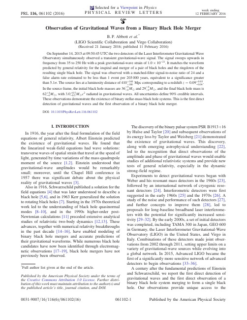
Observation of Gravitational Waves from a Binary Black Hole MergerB.P.Abbott et al.*(LIGO Scientific Collaboration and Virgo Collaboration)(Received21January2016;published11February2016)On September14,2015at09:50:45UTC the two detectors of the Laser Interferometer Gravitational-Wave Observatory simultaneously observed a transient gravitational-wave signal.The signal sweeps upwards in frequency from35to250Hz with a peak gravitational-wave strain of1.0×10−21.It matches the waveform predicted by general relativity for the inspiral and merger of a pair of black holes and the ringdown of the resulting single black hole.The signal was observed with a matched-filter signal-to-noise ratio of24and a false alarm rate estimated to be less than1event per203000years,equivalent to a significance greaterthan5.1σ.The source lies at a luminosity distance of410þ160−180Mpc corresponding to a redshift z¼0.09þ0.03−0.04.In the source frame,the initial black hole masses are36þ5−4M⊙and29þ4−4M⊙,and the final black hole mass is62þ4−4M⊙,with3.0þ0.5−0.5M⊙c2radiated in gravitational waves.All uncertainties define90%credible intervals.These observations demonstrate the existence of binary stellar-mass black hole systems.This is the first direct detection of gravitational waves and the first observation of a binary black hole merger.DOI:10.1103/PhysRevLett.116.061102I.INTRODUCTIONIn1916,the year after the final formulation of the field equations of general relativity,Albert Einstein predicted the existence of gravitational waves.He found that the linearized weak-field equations had wave solutions: transverse waves of spatial strain that travel at the speed of light,generated by time variations of the mass quadrupole moment of the source[1,2].Einstein understood that gravitational-wave amplitudes would be remarkably small;moreover,until the Chapel Hill conference in 1957there was significant debate about the physical reality of gravitational waves[3].Also in1916,Schwarzschild published a solution for the field equations[4]that was later understood to describe a black hole[5,6],and in1963Kerr generalized the solution to rotating black holes[7].Starting in the1970s theoretical work led to the understanding of black hole quasinormal modes[8–10],and in the1990s higher-order post-Newtonian calculations[11]preceded extensive analytical studies of relativistic two-body dynamics[12,13].These advances,together with numerical relativity breakthroughs in the past decade[14–16],have enabled modeling of binary black hole mergers and accurate predictions of their gravitational waveforms.While numerous black hole candidates have now been identified through electromag-netic observations[17–19],black hole mergers have not previously been observed.The discovery of the binary pulsar system PSR B1913þ16 by Hulse and Taylor[20]and subsequent observations of its energy loss by Taylor and Weisberg[21]demonstrated the existence of gravitational waves.This discovery, along with emerging astrophysical understanding[22], led to the recognition that direct observations of the amplitude and phase of gravitational waves would enable studies of additional relativistic systems and provide new tests of general relativity,especially in the dynamic strong-field regime.Experiments to detect gravitational waves began with Weber and his resonant mass detectors in the1960s[23], followed by an international network of cryogenic reso-nant detectors[24].Interferometric detectors were first suggested in the early1960s[25]and the1970s[26].A study of the noise and performance of such detectors[27], and further concepts to improve them[28],led to proposals for long-baseline broadband laser interferome-ters with the potential for significantly increased sensi-tivity[29–32].By the early2000s,a set of initial detectors was completed,including TAMA300in Japan,GEO600 in Germany,the Laser Interferometer Gravitational-Wave Observatory(LIGO)in the United States,and Virgo in binations of these detectors made joint obser-vations from2002through2011,setting upper limits on a variety of gravitational-wave sources while evolving into a global network.In2015,Advanced LIGO became the first of a significantly more sensitive network of advanced detectors to begin observations[33–36].A century after the fundamental predictions of Einstein and Schwarzschild,we report the first direct detection of gravitational waves and the first direct observation of a binary black hole system merging to form a single black hole.Our observations provide unique access to the*Full author list given at the end of the article.Published by the American Physical Society under the terms of the Creative Commons Attribution3.0License.Further distri-bution of this work must maintain attribution to the author(s)and the published article’s title,journal citation,and DOI.properties of space-time in the strong-field,high-velocity regime and confirm predictions of general relativity for the nonlinear dynamics of highly disturbed black holes.II.OBSERVATIONOn September14,2015at09:50:45UTC,the LIGO Hanford,W A,and Livingston,LA,observatories detected the coincident signal GW150914shown in Fig.1.The initial detection was made by low-latency searches for generic gravitational-wave transients[41]and was reported within three minutes of data acquisition[43].Subsequently, matched-filter analyses that use relativistic models of com-pact binary waveforms[44]recovered GW150914as the most significant event from each detector for the observa-tions reported here.Occurring within the10-msintersite FIG.1.The gravitational-wave event GW150914observed by the LIGO Hanford(H1,left column panels)and Livingston(L1,rightcolumn panels)detectors.Times are shown relative to September14,2015at09:50:45UTC.For visualization,all time series are filtered with a35–350Hz bandpass filter to suppress large fluctuations outside the detectors’most sensitive frequency band,and band-reject filters to remove the strong instrumental spectral lines seen in the Fig.3spectra.Top row,left:H1strain.Top row,right:L1strain.GW150914arrived first at L1and6.9þ0.5−0.4ms later at H1;for a visual comparison,the H1data are also shown,shifted in time by this amount and inverted(to account for the detectors’relative orientations).Second row:Gravitational-wave strain projected onto each detector in the35–350Hz band.Solid lines show a numerical relativity waveform for a system with parameters consistent with those recovered from GW150914[37,38]confirmed to99.9%by an independent calculation based on[15].Shaded areas show90%credible regions for two independent waveform reconstructions.One(dark gray)models the signal using binary black hole template waveforms [39].The other(light gray)does not use an astrophysical model,but instead calculates the strain signal as a linear combination of sine-Gaussian wavelets[40,41].These reconstructions have a94%overlap,as shown in[39].Third row:Residuals after subtracting the filtered numerical relativity waveform from the filtered detector time series.Bottom row:A time-frequency representation[42]of the strain data,showing the signal frequency increasing over time.propagation time,the events have a combined signal-to-noise ratio(SNR)of24[45].Only the LIGO detectors were observing at the time of GW150914.The Virgo detector was being upgraded, and GEO600,though not sufficiently sensitive to detect this event,was operating but not in observational mode.With only two detectors the source position is primarily determined by the relative arrival time and localized to an area of approximately600deg2(90% credible region)[39,46].The basic features of GW150914point to it being produced by the coalescence of two black holes—i.e., their orbital inspiral and merger,and subsequent final black hole ringdown.Over0.2s,the signal increases in frequency and amplitude in about8cycles from35to150Hz,where the amplitude reaches a maximum.The most plausible explanation for this evolution is the inspiral of two orbiting masses,m1and m2,due to gravitational-wave emission.At the lower frequencies,such evolution is characterized by the chirp mass[11]M¼ðm1m2Þ3=5121=5¼c3G596π−8=3f−11=3_f3=5;where f and_f are the observed frequency and its time derivative and G and c are the gravitational constant and speed of light.Estimating f and_f from the data in Fig.1, we obtain a chirp mass of M≃30M⊙,implying that the total mass M¼m1þm2is≳70M⊙in the detector frame. This bounds the sum of the Schwarzschild radii of thebinary components to2GM=c2≳210km.To reach an orbital frequency of75Hz(half the gravitational-wave frequency)the objects must have been very close and very compact;equal Newtonian point masses orbiting at this frequency would be only≃350km apart.A pair of neutron stars,while compact,would not have the required mass,while a black hole neutron star binary with the deduced chirp mass would have a very large total mass, and would thus merge at much lower frequency.This leaves black holes as the only known objects compact enough to reach an orbital frequency of75Hz without contact.Furthermore,the decay of the waveform after it peaks is consistent with the damped oscillations of a black hole relaxing to a final stationary Kerr configuration. Below,we present a general-relativistic analysis of GW150914;Fig.2shows the calculated waveform using the resulting source parameters.III.DETECTORSGravitational-wave astronomy exploits multiple,widely separated detectors to distinguish gravitational waves from local instrumental and environmental noise,to provide source sky localization,and to measure wave polarizations. The LIGO sites each operate a single Advanced LIGO detector[33],a modified Michelson interferometer(see Fig.3)that measures gravitational-wave strain as a differ-ence in length of its orthogonal arms.Each arm is formed by two mirrors,acting as test masses,separated by L x¼L y¼L¼4km.A passing gravitational wave effec-tively alters the arm lengths such that the measured difference isΔLðtÞ¼δL x−δL y¼hðtÞL,where h is the gravitational-wave strain amplitude projected onto the detector.This differential length variation alters the phase difference between the two light fields returning to the beam splitter,transmitting an optical signal proportional to the gravitational-wave strain to the output photodetector. To achieve sufficient sensitivity to measure gravitational waves,the detectors include several enhancements to the basic Michelson interferometer.First,each arm contains a resonant optical cavity,formed by its two test mass mirrors, that multiplies the effect of a gravitational wave on the light phase by a factor of300[48].Second,a partially trans-missive power-recycling mirror at the input provides addi-tional resonant buildup of the laser light in the interferometer as a whole[49,50]:20W of laser input is increased to700W incident on the beam splitter,which is further increased to 100kW circulating in each arm cavity.Third,a partially transmissive signal-recycling mirror at the outputoptimizes FIG. 2.Top:Estimated gravitational-wave strain amplitude from GW150914projected onto H1.This shows the full bandwidth of the waveforms,without the filtering used for Fig.1. The inset images show numerical relativity models of the black hole horizons as the black holes coalesce.Bottom:The Keplerian effective black hole separation in units of Schwarzschild radii (R S¼2GM=c2)and the effective relative velocity given by the post-Newtonian parameter v=c¼ðGMπf=c3Þ1=3,where f is the gravitational-wave frequency calculated with numerical relativity and M is the total mass(value from Table I).the gravitational-wave signal extraction by broadening the bandwidth of the arm cavities [51,52].The interferometer is illuminated with a 1064-nm wavelength Nd:Y AG laser,stabilized in amplitude,frequency,and beam geometry [53,54].The gravitational-wave signal is extracted at the output port using a homodyne readout [55].These interferometry techniques are designed to maxi-mize the conversion of strain to optical signal,thereby minimizing the impact of photon shot noise (the principal noise at high frequencies).High strain sensitivity also requires that the test masses have low displacement noise,which is achieved by isolating them from seismic noise (low frequencies)and designing them to have low thermal noise (intermediate frequencies).Each test mass is suspended as the final stage of a quadruple-pendulum system [56],supported by an active seismic isolation platform [57].These systems collectively provide more than 10orders of magnitude of isolation from ground motion for frequen-cies above 10Hz.Thermal noise is minimized by using low-mechanical-loss materials in the test masses and their suspensions:the test masses are 40-kg fused silica substrates with low-loss dielectric optical coatings [58,59],and are suspended with fused silica fibers from the stage above [60].To minimize additional noise sources,all components other than the laser source are mounted on vibration isolation stages in ultrahigh vacuum.To reduce optical phase fluctuations caused by Rayleigh scattering,the pressure in the 1.2-m diameter tubes containing the arm-cavity beams is maintained below 1μPa.Servo controls are used to hold the arm cavities on resonance [61]and maintain proper alignment of the optical components [62].The detector output is calibrated in strain by measuring its response to test mass motion induced by photon pressure from a modulated calibration laser beam [63].The calibration is established to an uncertainty (1σ)of less than 10%in amplitude and 10degrees in phase,and is continuously monitored with calibration laser excitations at selected frequencies.Two alternative methods are used to validate the absolute calibration,one referenced to the main laser wavelength and the other to a radio-frequencyoscillator(a)FIG.3.Simplified diagram of an Advanced LIGO detector (not to scale).A gravitational wave propagating orthogonally to the detector plane and linearly polarized parallel to the 4-km optical cavities will have the effect of lengthening one 4-km arm and shortening the other during one half-cycle of the wave;these length changes are reversed during the other half-cycle.The output photodetector records these differential cavity length variations.While a detector ’s directional response is maximal for this case,it is still significant for most other angles of incidence or polarizations (gravitational waves propagate freely through the Earth).Inset (a):Location and orientation of the LIGO detectors at Hanford,WA (H1)and Livingston,LA (L1).Inset (b):The instrument noise for each detector near the time of the signal detection;this is an amplitude spectral density,expressed in terms of equivalent gravitational-wave strain amplitude.The sensitivity is limited by photon shot noise at frequencies above 150Hz,and by a superposition of other noise sources at lower frequencies [47].Narrow-band features include calibration lines (33–38,330,and 1080Hz),vibrational modes of suspension fibers (500Hz and harmonics),and 60Hz electric power grid harmonics.[64].Additionally,the detector response to gravitational waves is tested by injecting simulated waveforms with the calibration laser.To monitor environmental disturbances and their influ-ence on the detectors,each observatory site is equipped with an array of sensors:seismometers,accelerometers, microphones,magnetometers,radio receivers,weather sensors,ac-power line monitors,and a cosmic-ray detector [65].Another∼105channels record the interferometer’s operating point and the state of the control systems.Data collection is synchronized to Global Positioning System (GPS)time to better than10μs[66].Timing accuracy is verified with an atomic clock and a secondary GPS receiver at each observatory site.In their most sensitive band,100–300Hz,the current LIGO detectors are3to5times more sensitive to strain than initial LIGO[67];at lower frequencies,the improvement is even greater,with more than ten times better sensitivity below60Hz.Because the detectors respond proportionally to gravitational-wave amplitude,at low redshift the volume of space to which they are sensitive increases as the cube of strain sensitivity.For binary black holes with masses similar to GW150914,the space-time volume surveyed by the observations reported here surpasses previous obser-vations by an order of magnitude[68].IV.DETECTOR VALIDATIONBoth detectors were in steady state operation for several hours around GW150914.All performance measures,in particular their average sensitivity and transient noise behavior,were typical of the full analysis period[69,70]. Exhaustive investigations of instrumental and environ-mental disturbances were performed,giving no evidence to suggest that GW150914could be an instrumental artifact [69].The detectors’susceptibility to environmental disturb-ances was quantified by measuring their response to spe-cially generated magnetic,radio-frequency,acoustic,and vibration excitations.These tests indicated that any external disturbance large enough to have caused the observed signal would have been clearly recorded by the array of environ-mental sensors.None of the environmental sensors recorded any disturbances that evolved in time and frequency like GW150914,and all environmental fluctuations during the second that contained GW150914were too small to account for more than6%of its strain amplitude.Special care was taken to search for long-range correlated disturbances that might produce nearly simultaneous signals at the two sites. No significant disturbances were found.The detector strain data exhibit non-Gaussian noise transients that arise from a variety of instrumental mecha-nisms.Many have distinct signatures,visible in auxiliary data channels that are not sensitive to gravitational waves; such instrumental transients are removed from our analyses [69].Any instrumental transients that remain in the data are accounted for in the estimated detector backgrounds described below.There is no evidence for instrumental transients that are temporally correlated between the two detectors.V.SEARCHESWe present the analysis of16days of coincident observations between the two LIGO detectors from September12to October20,2015.This is a subset of the data from Advanced LIGO’s first observational period that ended on January12,2016.GW150914is confidently detected by two different types of searches.One aims to recover signals from the coalescence of compact objects,using optimal matched filtering with waveforms predicted by general relativity. The other search targets a broad range of generic transient signals,with minimal assumptions about waveforms.These searches use independent methods,and their response to detector noise consists of different,uncorrelated,events. However,strong signals from binary black hole mergers are expected to be detected by both searches.Each search identifies candidate events that are detected at both observatories consistent with the intersite propa-gation time.Events are assigned a detection-statistic value that ranks their likelihood of being a gravitational-wave signal.The significance of a candidate event is determined by the search background—the rate at which detector noise produces events with a detection-statistic value equal to or higher than the candidate event.Estimating this back-ground is challenging for two reasons:the detector noise is nonstationary and non-Gaussian,so its properties must be empirically determined;and it is not possible to shield the detector from gravitational waves to directly measure a signal-free background.The specific procedure used to estimate the background is slightly different for the two searches,but both use a time-shift technique:the time stamps of one detector’s data are artificially shifted by an offset that is large compared to the intersite propagation time,and a new set of events is produced based on this time-shifted data set.For instrumental noise that is uncor-related between detectors this is an effective way to estimate the background.In this process a gravitational-wave signal in one detector may coincide with time-shifted noise transients in the other detector,thereby contributing to the background estimate.This leads to an overestimate of the noise background and therefore to a more conservative assessment of the significance of candidate events.The characteristics of non-Gaussian noise vary between different time-frequency regions.This means that the search backgrounds are not uniform across the space of signals being searched.To maximize sensitivity and provide a better estimate of event significance,the searches sort both their background estimates and their event candidates into differ-ent classes according to their time-frequency morphology. The significance of a candidate event is measured against the background of its class.To account for having searchedmultiple classes,this significance is decreased by a trials factor equal to the number of classes [71].A.Generic transient searchDesigned to operate without a specific waveform model,this search identifies coincident excess power in time-frequency representations of the detector strain data [43,72],for signal frequencies up to 1kHz and durations up to a few seconds.The search reconstructs signal waveforms consistent with a common gravitational-wave signal in both detectors using a multidetector maximum likelihood method.Each event is ranked according to the detection statistic ηc ¼ffiffiffiffiffiffiffiffiffiffiffiffiffiffiffiffiffiffiffiffiffiffiffiffiffiffiffiffiffiffiffiffiffiffiffi2E c =ð1þE n =E c Þp ,where E c is the dimensionless coherent signal energy obtained by cross-correlating the two reconstructed waveforms,and E n is the dimensionless residual noise energy after the reconstructed signal is subtracted from the data.The statistic ηc thus quantifies the SNR of the event and the consistency of the data between the two detectors.Based on their time-frequency morphology,the events are divided into three mutually exclusive search classes,as described in [41]:events with time-frequency morphology of known populations of noise transients (class C1),events with frequency that increases with time (class C3),and all remaining events (class C2).Detected with ηc ¼20.0,GW150914is the strongest event of the entire search.Consistent with its coalescence signal signature,it is found in the search class C3of events with increasing time-frequency evolution.Measured on a background equivalent to over 67400years of data and including a trials factor of 3to account for the search classes,its false alarm rate is lower than 1in 22500years.This corresponds to a probability <2×10⁻⁶of observing one or more noise events as strong as GW150914during the analysis time,equivalent to 4.6σ.The left panel of Fig.4shows the C3class results and background.The selection criteria that define the search class C3reduce the background by introducing a constraint on the signal morphology.In order to illustrate the significance of GW150914against a background of events with arbitrary shapes,we also show the results of a search that uses the same set of events as the one described above but without this constraint.Specifically,we use only two search classes:the C1class and the union of C2and C3classes (C 2þC 3).In this two-class search the GW150914event is found in the C 2þC 3class.The left panel of Fig.4shows the C 2þC 3class results and background.In the background of this class there are four events with ηc ≥32.1,yielding a false alarm rate for GW150914of 1in 8400years.This corresponds to a false alarm probability of 5×10⁻⁶equivalent to 4.4σ.FIG.4.Search results from the generic transient search (left)and the binary coalescence search (right).These histograms show the number of candidate events (orange markers)and the mean number of background events (black lines)in the search class where GW150914was found as a function of the search detection statistic and with a bin width of 0.2.The scales on the top give the significance of an event in Gaussian standard deviations based on the corresponding noise background.The significance of GW150914is greater than 5.1σand 4.6σfor the binary coalescence and the generic transient searches,respectively.Left:Along with the primary search (C3)we also show the results (blue markers)and background (green curve)for an alternative search that treats events independently of their frequency evolution (C 2þC 3).The classes C2and C3are defined in the text.Right:The tail in the black-line background of the binary coalescence search is due to random coincidences of GW150914in one detector with noise in the other detector.(This type of event is practically absent in the generic transient search background because they do not pass the time-frequency consistency requirements used in that search.)The purple curve is the background excluding those coincidences,which is used to assess the significance of the second strongest event.For robustness and validation,we also use other generic transient search algorithms[41].A different search[73]and a parameter estimation follow-up[74]detected GW150914 with consistent significance and signal parameters.B.Binary coalescence searchThis search targets gravitational-wave emission from binary systems with individual masses from1to99M⊙, total mass less than100M⊙,and dimensionless spins up to 0.99[44].To model systems with total mass larger than 4M⊙,we use the effective-one-body formalism[75],whichcombines results from the post-Newtonian approach [11,76]with results from black hole perturbation theory and numerical relativity.The waveform model[77,78] assumes that the spins of the merging objects are alignedwith the orbital angular momentum,but the resultingtemplates can,nonetheless,effectively recover systemswith misaligned spins in the parameter region ofGW150914[44].Approximately250000template wave-forms are used to cover this parameter space.The search calculates the matched-filter signal-to-noiseratioρðtÞfor each template in each detector and identifiesmaxima ofρðtÞwith respect to the time of arrival of the signal[79–81].For each maximum we calculate a chi-squared statisticχ2r to test whether the data in several differentfrequency bands are consistent with the matching template [82].Values ofχ2r near unity indicate that the signal is consistent with a coalescence.Ifχ2r is greater than unity,ρðtÞis reweighted asˆρ¼ρ=f½1þðχ2rÞ3 =2g1=6[83,84].The final step enforces coincidence between detectors by selectingevent pairs that occur within a15-ms window and come fromthe same template.The15-ms window is determined by the10-ms intersite propagation time plus5ms for uncertainty inarrival time of weak signals.We rank coincident events basedon the quadrature sumˆρc of theˆρfrom both detectors[45]. To produce background data for this search the SNR maxima of one detector are time shifted and a new set of coincident events is computed.Repeating this procedure ∼107times produces a noise background analysis time equivalent to608000years.To account for the search background noise varying acrossthe target signal space,candidate and background events aredivided into three search classes based on template length.The right panel of Fig.4shows the background for thesearch class of GW150914.The GW150914detection-statistic value ofˆρc¼23.6is larger than any background event,so only an upper bound can be placed on its false alarm rate.Across the three search classes this bound is1in 203000years.This translates to a false alarm probability <2×10⁻⁷,corresponding to5.1σ.A second,independent matched-filter analysis that uses adifferent method for estimating the significance of itsevents[85,86],also detected GW150914with identicalsignal parameters and consistent significance.When an event is confidently identified as a real gravitational-wave signal,as for GW150914,the back-ground used to determine the significance of other events is reestimated without the contribution of this event.This is the background distribution shown as a purple line in the right panel of Fig.4.Based on this,the second most significant event has a false alarm rate of1per2.3years and corresponding Poissonian false alarm probability of0.02. Waveform analysis of this event indicates that if it is astrophysical in origin it is also a binary black hole merger[44].VI.SOURCE DISCUSSIONThe matched-filter search is optimized for detecting signals,but it provides only approximate estimates of the source parameters.To refine them we use general relativity-based models[77,78,87,88],some of which include spin precession,and for each model perform a coherent Bayesian analysis to derive posterior distributions of the source parameters[89].The initial and final masses, final spin,distance,and redshift of the source are shown in Table I.The spin of the primary black hole is constrained to be<0.7(90%credible interval)indicating it is not maximally spinning,while the spin of the secondary is only weakly constrained.These source parameters are discussed in detail in[39].The parameter uncertainties include statistical errors and systematic errors from averaging the results of different waveform models.Using the fits to numerical simulations of binary black hole mergers in[92,93],we provide estimates of the mass and spin of the final black hole,the total energy radiated in gravitational waves,and the peak gravitational-wave luminosity[39].The estimated total energy radiated in gravitational waves is3.0þ0.5−0.5M⊙c2.The system reached apeak gravitational-wave luminosity of3.6þ0.5−0.4×1056erg=s,equivalent to200þ30−20M⊙c2=s.Several analyses have been performed to determine whether or not GW150914is consistent with a binary TABLE I.Source parameters for GW150914.We report median values with90%credible intervals that include statistical errors,and systematic errors from averaging the results of different waveform models.Masses are given in the source frame;to convert to the detector frame multiply by(1þz) [90].The source redshift assumes standard cosmology[91]. Primary black hole mass36þ5−4M⊙Secondary black hole mass29þ4−4M⊙Final black hole mass62þ4−4M⊙Final black hole spin0.67þ0.05−0.07 Luminosity distance410þ160−180MpcSource redshift z0.09þ0.03−0.04。
什么是MIS

什么是MIS? What you to remember is that the sole focus of MIS is not technology.你要记住的是,MIS的唯一重点不是技术什么是电子商务? Electronic commerce is commerce ,but it is commerce accelerated and enhanced by information technology , in particular , the internet. 电子商务是商业的,但它是由信息技术、商务加速和增强特别是互联网。
什么是即时经济? The “NOw ”economy is one characterized by the immediate access customers have to the ordering of products and services.(ATM are an obvious and simple example .Using anATM ,you have access to your money any time of the day or night and just about any where in the world. )“现在”经济是一个以立即访问客户订购的产品和服务。
(ATM是一个明显的和简单的例子。
使用自动取款机,你可以访问你的钱白天或晚上的任何时间和任何地方在世界上。
)什么是global经济? A global economy is one in whichcustomers ,businesses,suppliers,distributors,and manufacturers all operate whitout regard to physical and geographical boundaries. 全球经济中,客户、企业、供应商、分销商和制造商所有操作没有了对物理和地理边界。
2020考研英语真题一及答案解析

2020年研究生入学统一考试试题(英语一)Section I Use of EnglishDirections:Read the following text. Choose the best word (s) for each numbered blank and mark A, B, C or D on the ANSWER SHEET. (10 points)Even if families are less likely to sit down to eat together than was once the case, millions of Britons will none the less have partaken this weekend of one of the nation's great traditions: the Sunday roast. __1__ a cold winter's day, few culinary pleasures can __2__it. Yet as we report now, the food police are determined that this __3__ should be rendered yet another guilty pleasure __4__ to damage our health.The Food Standards Authority (FSA) has __5__ a public warning about the risks of a compound called acrylamide that forms in some foods cooked __6__ high temperatures.This means that people should __7__ crisping their roast potatoes, spurn thin-crust pizzas and only __8__ toast their bread. But where is the evidence to support such alarmist advice? __9__ studies have shown that acrylamide can cause neurological damage in mice, there is no __10__ evidence that it causes cancer in humans.Scientists say the compound is "__11__ to be carcinogenic" but have no hard scientific proof. __12__ the precautionary principle, it could be argued that it is __13__ to follow the FSA advice. __14__, it was rumored that smoking caused cancer for years before the evidence was found to prove a __15__.Doubtless a piece of boiled beef can always be __16__ up on Sunday alongside some steamed vegetables,without the Yorkshire pudding and no wine. But would life be worth living? __17__, the FSA says it is not telling people to cut out roast foods __18__, but to reduce their lifetime intake. However, their __19__ risks coming across as exhortation and nannying. Constant health scares just __20__ with no one listening.1. A In B Towards C On D Till2. A match B express C satisfy D influence3. A patience B enjoyment C surprise D concern4. A intensified B privileged C compelled D guaranteed5. A issued B received C ignored D canceled6. A under B at C for D by7. A forget B regret C finish D avoid8. A partially B regularly C easily D initially9. A Unless B Since C If D While10. A secondary B external C inconclusive D negative11. A insufficient B bound C likely D slow12. A On the basis of B At the cost of C In addition to D In contrast to13. A interesting B advisable C urgent D fortunate14. A As usual B In particular C By definition D After all15. A resemblance B combination C connection D pattern16. A made B served C saved D used17. A To be fair B For instance C To be brief D in general18. A reluctantly B entirely C gradually D carefully19. A promise B experience C campaign D competition20.A follow up B pick up C open up D end upSection II Reading ComprehensionPart A Directions:Read the following four texts. Answer the questions below each text by choosing [A], [B], [C], or [D]. Mark your answers on the ANSWER SHEET. (40 points)Text 1A group of labour MPs, among them Yvette Cooper, are bringing in the new year with a call to institute a UK “town of culture” award. The proposal is that it should sit alongsid e the existing city of culture title, which was held by Hull in 2017 and has been awarded to Coventry for zoz1. Cooper and her colleagues argue that the success of the crown for Hull, where it brought in £220m of investment and an avalanche of arts, out no t to be confined to cities. Britain’ town, it is true are not prevented from applying, but they generally lack the resources to put together a bit to beat their bigger competitions. A town of culture award could, it is argued, become an annual event, attracting funding and creating jobs.Some might see the proposal as a boo by prize for the fact that Britain is no longer be able to apply for the much more prestigious title of European capital of culture, a sough-after award bagged by Glasgow in 1990 and Liverpool in 2008. A cynic might speculate that the UK is on the verge of disappearing into an endless fever of self-celebration in its desperation to reinvent itself for the post-Brexit world: after town of culture, who knows that will follow— village of culture? Suburb of culture? Hamlet of culture?It is also wise lo recall that such titles are not a cure-all. A badly run “year of culture” washes in and out of a place like the tide, bringing prominence for a spell but leaving no lasting benefits to the community. The really successful holders of such titles are those that do a great deal more than fill hotel bedrooms and bring in high-profile arts events and good press for a year. They transform the aspirations of the people who live there; they nudge the self-image of the city into a bolder and more optimistic light. It is hard to get right, and requires a remarkable degree of vision, as well as cooperation between city authorities, the private sector, community. groups and cultural organisations. But it can be done: Glasgow’s year as European capital of culture can certainly be seen as one of complex series of factors that have turned the city into the power of art, music and theatre that it remains today.A “town of culture” could be not just about the arts but about honouring a town’s peculiarities—helping sustain its high street, supporting local facilities and above all celebrating its people and turn it into action.21. Cooper and her colleagues argue that a “town of culture” award could[A] consolidate the town-city ties in Britain.[B] promote cooperation among Britain’s towns.[C] increase the economic strength of Britain’s towns.[D] focus Britain’s limited resources on cultural events.22. According to Paragraph 2, the proposal might be regarded by some as[A] a sensible compromise.[B] a self-deceiving attempt.[C] an eye-catching bonus.[D] an inaccessible target.23. The author suggests that a title holder is successful only if it[A] endeavours to maintain its image.[B] meets the aspirations of its people.[C] brings its local arts to prominence.[D] commits to its long-term growth.24. Glasgow is mentioned in Paragraph 3 to present[A] a contrasting case. (B] a supporting example.[C] a background story. [D] a related topic.25. What is the author’s attitude towards the proposal?[A] Skeptical. [B] Objective. [C] Favourable. [D]Critical.Text 2Scientific publishing has long been a licence to print money. Scientists need journals in which to publish their research, so they will supply the articles without monetary reward. Other scientists perform the specialised work of peer review also for free, because it is a central element in the acquisition of status and the production of scientific knowledge.With the content of papers secured for free, the publisher needs only find a market for its journal. Until this century, university libraries were not very price sensitive. Scientific publishers routinely report profit margins approaching 40% on their operations, at a time when the rest of the publishing industry is in an existential crisis.The Dutch giant Elsevier, which claims to publish 25% of the scientific papers produced in the world, made profits of more than £900m last year, while UK universities alone spent more than £210m in 2016 to enable researchers to access their own publicly funded research; both figures seem to rise unstoppably despite increasingly desperate efforts to change them.The most drastic, and thoroughly illegal, reaction has been the emergence of Sci-Hub, a kind of global photocopier for scientific papers, set up in 2012, which now claims to offer access to every paywalled article published since 2015. The success of Sci-Hub, which relies on researchers passing on copies they have themselves legally accessed, shows the legal ecosystem has lost legitimacy among is users and must be transformed so that it works for all participants.In Britain the move towards open access publishing has been driven by funding bodies. In some ways it has been very successful. More than half of all British scientific research is now published under open access terms: either freely available from the moment of publication, or paywalled for a year or more so that the publishers can make a profit before being placed on general release.Yet the new system has not worked out any cheaper for the universities. Publishers have responded to the demand that they make their product free to readers by charging their writersfees to cover the costs of preparing an article. These range from around £500 to $5,000. A report last year pointed out that the costs both of subscriptions and of these “article preparation costs" had been steadily rising at a rate above inflation. In some ways the scientific publishing model resembles the economy of the social internet: labour is provided free in exchange for the hope of status, while huge profits are made by a few big firms who run the market places. In both cases, we need a rebalancing of power.26. Sc ientific publishing is seen as “a licence to print money” partly because[A] its funding has enjoyed a steady increase.[B] its marketing strategy has been successful.[C] its payment for peer review is reduced.[D] its content acquisition costs nothing.27. According to Paragraphs 2 and 3, scientific publishers Elsevier have[A] thrived mainly on university libraries.[B] gone through an existential crisis.[C] revived the publishing industry.[D] financed researchers generously.28. How does the author feel about the success of Sci-Hub?[A] Relieved. [B] Puzzled.[C] Concerned. [D] Encouraged.29. It can be learned from Paragraphs 5 and 6 that open access terms .[A] allow publishers some room to make money.[B] render publishing much easier for scientists.[C] reduce the cost of publication substantially[D] free universities from financial burdens.30. Which of the following characteristics the scientific publishing model?[A] Trial subscription is offered.[B] Labour triumphs over status.[C]Costs are well controlled.[D]The few feed on the many.Text 3Progressives often support diversity mandates as a path to equality and a way to level the playing field. But all too often such policies are an insincere form of virtue-signaling that benefits only the most privileged and does little to help average people.A pair of bills sponsored by Massachusetts state Senator Jason Lewis and HouseSpeaker Pro Tempore Patricia Haddad, to ensure “gender parity” on boards and commissions, provide a case in point.Had dad and Lewis are concerned that more than half the state-government boards are less than 40 percent female. In order to ensure that elite women have more such opportunities, they have proposed imposing government quotas. If the bills become law, state boards and commissions will be required to set aside 50 percent of board seats for women by 2022.The bills are similar to a measure recently adopted in California, which last year became the first state to require gender quotas for private companies. In signing the measure, California Governor Jerry Brown admitted that the law, which expressly classifies people on the basis of sex, is probably unconstitutional.The US Supreme Court frowns on sex-based classifications unless they are designed to address an “important” policy interest, Because the California law applies to all boards, even where there is no history of prior discrimination, courts are likely to rule that the law violates the constitutional guarantee of “equal protection”.But are such government mandates even necessary? Female participation on corporate boards may not currently mirror the percentage of women in the general population, but so what?The number of women on corporate boards has been steadily increasing without government interference. According to a study by Catalyst, between 2010 and 2015 the share of women on the boards of global corporations increased by 54 percent.Requiring companies to make gender the primary qualification for board membership will inevitably lead to less experienced private sector boards. That is exactly what happened when Norway adopted a nationwide corporate gender quota.Writing in The New Republic, Alice Lee notes that increasing the number of opportunities for board membership without increasing the pool of qualified women to serve on such boards has led to a “golden skirt” phenomenon. where the same elite women scoop up multiple seats on a variety of boards.Next time somebody pushes corporate quotas as a way to promote gender equity, remember that such policies are largely self-serving measures that make their sponsors feel good but do little to help average women.31. The author believes hat the bills sponsored by Lewis and Haddad will[A] help lite to reduce gender bias.[B] pose a threat to the state government.[C] raise women’s position in politics.[D] greatly broaden career options.32. Which of the following is true of the California measure?[A] It has irritated private business owners.[B] It is welcomed by the Supreme Court.[C]It may go against the Constitution.[D] It will settle the prior controversies.33. The author mentions the study by Catalyst to illustrate[A] the harm from arbitrary board decision.[B] the importance of constitutional guarantees.[C] the pressure on women in global corporations.[D] the needlessness of government interventions.34. Norway’s adoption of a nationwide corporate gender quota has led to[A] the underestimation of elite women’s role.[B] the objection to female participation on bards.[C] the entry of unqualified candidates into the board.[D] the growing tension between Labor and management.35. Which of the following can be inferred from the text?[A] Women’s need in employment should be considered[B] Feasibility should be a prime concern in policymaking.[C] Everyone should try hard to promote social justice.[D]Major social issues should be the focus of legislation.Text 4Last Thursday, the French Senate passed a digital services tax, which would impose an entirely new tax on large multinationals that provide digital services to consumers or users in France. Digital services include everything from providing a platform for selling goods and services online to targeting advertising based on user data. and the tax applies to gross revenue from such services. Many French politicians and media outlets have referred to this as a“GAFA tax," meaning that it is designed to apply primarily to companies such as Google, Apple, Facebook and Amazon — in other words, multinational tech companies based in the United States.The digital services tax now awaits the signature of President Emmanuel Macron, who has expressed support for the measure, and it could go into effect within the next few weeks. But it has already sparked significant controversy, with the Unite States trade representative opening an investigation into whether the tax discriminates against American companies, which in turn could lead to trade sanctions against France.The French tax is not just a unilateral move by one country in need of revenue. Instead, the digital services tax is part of a much larger trend, with countries over the past few years proposing or putting in place an alphabet soup of new international tax provisions. These have included Britain's DPT (diverted profits tax), Australia's MAAL (multinational antiavoidance law), and India's SEP (significant economic presence) test, to. name but a few. At the same time, the European Union, Spain, Britain and several other countries have all seriously contemplated digital services taxes.These unilateral developments differ in their specifics, but they are all designed to tax multinationals on income and revenue that countries believe they should have a right to tax, even if international tax rules do not grant them that right. In other words, they all share a view that the international tax system has failed to keep up with the current economy.In response to these many unilateral measures, the Organization for Economic Cooperation and Development (OECD) is currently working with 131 countries to reach a consensus by the end of 2020 on an international solution. Both France and the United States are involved in the organization's work, but France's digital services tax and the American response raise questions about what the future holds for the international tax system.France's planned tax is a clear waning: Unless a broad consensus can be reached on reforming the international tax system. other nations are likely to follow suit, and American companies will face a cascade of different taxes from dozens of nations that will prove burdensome and costly.36. The French Senate has passed a bill to[A] regulate digital services platforms.[B] protect French companies' interests.[C] impose a levy on tech multinationals.[D] curb the influence of advertising.37. It can be learned from Paragraph 2 that the digital services tax[A] may trigger countermeasures against France.[B] is apt to arouse criticism at home and abroad.[C] aims to ease international trade tensions.[D] will prompt the tech giants to quit France.38. The countries adopting the unilateral measures share the opinion that[A] redistribution of tech giants' revenue must be ensured.[B] the current international tax system needs upgrading[C] tech multinationals' monopoly should be prevented.[D] all countries ought to enjoy equal taxing rights.39. It can be learned from Paragraph 5 that the OECO's current work[A] is being resisted by US companies.[B] needs to be readjusted immediately.[C] is faced with uncertain prospects.[D] needs to involve more countries.40. Which of the following might be the best title for this text?[A] France Is Confronted with Trade Sanctions[B]France leads the charge on Digital Tax[C]France Says "NO" to Tech Multinationals[D] France Demands a Role in the Digital EconomyPart B Directions:Read the following text and answer the questions by choosing the most suitable subheading from the A-G for each of the numbered paragraph (41-45). There are two extra subheadings. Mark your answers on the ANSWER SHEET. (10 points)[A] Eye fixations are brief[B] Too much eye contact is instinctively felt to rude[C] Eye contact can be a friendly social signal[D] Personality can affect how a person reacts to eye contact[E] Biological factors behind eye contact are being investigated[F] Most people are not comfortable holding eye contact with strangers[G] Eye contact can also be aggressive.In a social situation, eye contact with another person can show that you are paying attention in a friendly way. But it can also be antagonistic such as when a political candidate turns toward their competitor during a debate and makes eye contact that signals hostility. Here’s what hard science reveals about eye contact:41.__________________________We know that a typical infant will instinctively gaze into its mother’s eyes, and she will look back. This mutual gaze is a major part of the attachment between mother and child. In adulthood, looking someone else in a pleasant way can be a complimentary sign of paying attention. It can catch someone’s attention in a crowded room, “Eye contact and smile” can signal availability and confidence, a common-sense notion supported in studies by psychologist Monica Moore.42.__________________________Neuroscientist Bonnie Augeung found that the hormone oxytocin increased the amount of eye contact from men toward the interviewer during a brief interview when the directionof their gaze was recorded. This was also found in high-functioning men with some autistic spectrum symptoms, who may tend to avoid eye contact. Specific brain regions that respond during direct gaze are being explored by other researches, using advanced methods of brain scanning.43.__________________________With the use of eye-tracking technology, Julia Minson of the Harvard Kennedy School of Government concluded that eye contact can signal very different kinds of messages, depending on the situation. While eye contact may be a sign of connection or trust in friendly situations, it’s more likely to be associated with dominance or intimidation in adversarial situations. “Whether you're a politician or a par ent, it might be helpful to keep in mind that trying to maintain eye contact may backfire if you're trying to convince someone who has a different set of beliefs than you,” said Minson.44.__________________________When we look at a face or a picture, our eyes pause on one spot at a time, often on the eyes or mouth. These pauses typically occur at about three per second, and the eyes then jump to another spot, until several important points in the image are registered like a series of snapshots. How the whole image is then assembled and perceived is still a mystery although it is the subject of current research.45.__________________________In people who score high in a test of neuroticism, a personality dimension associated with self-consciousness and anxiety, eye contact triggered more activity associated with avoidance, according to the Finnish researcher Jari Hietanen and colleagues. “Our findings indicate that people do not only feel different when they are the centre of attention but that their brain reactions also differ.” A more direct finding is that people who scored high for negative emotions like anxiety looked at others for shorter periods of time and reported more comfortable feelings when others did not look directly at them.Part C Directions:Read the following text carefully and then translate the underlined segments into Chinese. Your translation should be written neatly on the ANSWER SHEET. (10 points) Following the explosion of creativity in Florence during the 14th century known as the Renaissance, the modern world saw a departure from what it had once known. It turned from God and the authority of the Roman Catholic Church and instead favoured a more humanistic approach to being. Renaissance ideas had spread throughout Europe well into the 17th century, with the arts and sciences flourishing extraordinarily among those with a more logical disposition. (46)With the Church’s teachings and ways of thinking eclipsed by the Renaissance, the gap between the Medieval and modem periods had been bridged leading to new and unexplored intellectual territories.During the Renaissance, the great minds of Nicolaus Copernicus, Johannes Kepler and Galileo Galilei demonstrated the power of scientific study and discovery. (47)Before each of their revelations, many thinkers at the time had sustained more ancient ways of thinking, including the geo-centric view that the Earth was at the centre of our universe. Copernicus theorized in 1543 that all of the planets that we knew of revolved not around the Earth, but the Sun, a system that was later upheld by Galileo at his own expense. Offering up such a theory during a time of high tension between scientific and religious minds was branded as heresy, and any such heretics that continued to spread these lies were to be punished by imprisonment or even death.(48)Despite attempts by the Church to suppress this new generation of logicians andrationalists, more explanations for how the universe functioned were being made at a rate that the people could no longer ignore. It was with these great revelations that a new kind of philosophy founded in reason was born.The Church’s long standing dogma was losing the great battle for truth to rationalists and scientists. This very fact embodied the new ways of thinking that swept through Europe during most of 17th century. (49)As many took on the duty of trying to integrate reasoning and scientific philosophies into the world, the Renaissance was over and it was time for a new era—the Age of Reason.The 17th and 18th centuries were times of radical change and curiosity. Scientific method, reductionism and the questioning of Church ideals was to be encouraged, as were ideas of liberty, tolerance and progress. (50) Such actions to seek knowledge and to und erstand what information we already knew were captured by the Latin phrase ‘sapere aude’ or ‘dare to know’, after Immanuel Kant used it in his essay “An Answer to the Question: What is Enlightenment?”. It was the purpose and responsibility of great minds to go forth and seek out the truth, which they believed to be founded in knowledge.Section III WritingPart A51. Directions:The student union of your university has assigned you to inform the international students about an upcoming singing contest. Write a notice in about 100 words.Write your answer on the ANSWER SHEET.Do not use your own name in the notice. (10 points)Part B52. Directions:Write an essay of 160-200 words based on the pictures below. In your essay, you should1) describe the picture briefly,2) interpret the implied meaning, and3) give your comments.Write your answer on the ANSWER SHEET. (20 points)2020年考研英语一真题答案一、完形填空解析:今年完形填空的难度较前两年略难,虽然话题不难理解,但不易把握上下文的线索。
常见PHY芯片品牌介绍

常见 PHY芯片品牌介绍2019-01-07 11:39目前市场上百兆交换机是一个非常成熟的产品,各个芯片公司对自己的产品都进行了多次的优化和精简。
总的来说规格和性能方面都能满足作为2层傻瓜型交换机的应用。
一些主要的技术指标也基本相同。
所有公司的芯片都可以支持10/100M自适应;全线速交换;支持线序交叉功能。
下面我们将深入分析目前市场上采用的百兆交换机方案:1.Realtek 公司Realtek 公司相信大家比较熟悉,市场上百兆网卡大多采用他们公司8139芯片。
作为一个网络低端市场的芯片供应商16口和24口百兆交换机也是他们主推的产品。
Realtek公司百兆交换机方案的芯片型号为: RTL8316 + RTL8208;24口 RTL8324 + RTL8208。
Realtek公司采用的是MAC(媒介控制芯片)与 PHY(物理层芯片)相分离的架构。
RTL8316和RTL8324是MAC(媒介控制芯片),RTL8208是8口的PHY(物理层芯片)。
RTL8316 集成4 M 位DRAM 缓存用于数据包存储转发;RTL8324集成4 M 位缓存。
这个缓存的大小对于交换机处理数据的能力有着很大的影响!RTL8316和RTL8324 MAC地址表的深度为8K!2.ICPlus公司ICPlus公司也是台湾一家有着多年历史的网络芯片生产商。
ICPlus公司百兆交换机方案的芯片型号为:IP1726 + IP108。
同样ICPlus公司也采用MAC(媒介控制芯片)与 PHY(物理层芯片)相分离的架构。
IP1726是MAC(媒介控制芯片),IP108是8口的PHY(物理层芯片)。
IP1726集成1.5 M 位缓存用于数据包存储转发。
IP1726 MAC地址表的深度为4K!3.Admtek公司Admtek公司今年已经被德国英飞凌公司收购,实际上应该是德国公司。
Admtek公司百兆交换机方案的芯片型号为:ADM6926 + ADM7008。
实时荧光定量PCR仪qTOWER(RealtimePCR)
Quantitative real-time rapidPCR qTOWER | Quantitative real-time rapidPCRCombination of rapidPCR with real-time fluorescence detection Ideal for daily routine diagnosticsSimple and fast result analysis integrated into control softwareqTOWER | New, faster and easier quantitative real-time PCR New, faster and easier quantitative real-time PCR The qTOWER for routine real-time diagnostics is based on a novel fiber optical system patented by Analytik Jena. Furthermore it combines the advantages of exceptionally fast rapidPCR with ramping rates up to 12 °C/sec and a considerably sample consumption down to 5 µl per reaction. The test principle is build on robust homogeneous exonuclease assay or simple intercalating dyes, like SybrGreen. The detection of fluorescence signals takes place during each cycle, user-defined either during denaturation, annealing or elongation. Thereby the device is also suitable for easiest multi-component analysis.Subject to changes in design and scope of delivery as well as further technical development!March 2010, Analytik Jena AGAnalytik Jena AG Life ScienceKonrad-Zuse-Strasse 107745 Jena / Germany*****************************Phone +49 (0) 36 41 77 - 94 00Fax +49 (0) 36 41 77 - 76 77 76qPCRsoft – simple and clearBasis for the final analysis of the real-time PCR curves is the integrated software qPCRsoft. With this software the analytical evaluation of measured fluorescence signals referring to methods like absolute or relative quantification, delta-delta ct, allele discrimination or PCR efficiencies takes place. This control and analysis software allows the accurate determi-nation of concentrations or available allele conditions as well as ratios of expressions. Furthermore the complete system is extreme fast and permits the measurement by means of observing qPCR curves including analysis of up to 96 samples in parallel within less than 60 minutes. Thus the qTOWER in combination with qPCRsoft software represents an excellent, highly flexible and really fast real-time PCR device.Intuitive, fast and easy operation are hallmarks of the qTOWER software. It not only controls the rapidPCR reaction and recording of fluorescence signals per cycle, it also enables the final data analysis by a wide choice of different qPCR methods. Prepared for the futureTo meet different demands of applications, the qTOWER can be equipped with up to 4 different color modules for excitation and emission. Thereby the qTOWER can be customized, as a choice of the user out of 9 different available color modules. This keeps the system open for individually adaptations or changes. Therefore the instrument is ideally suited for multiplex applications and covers most currently available dyestuffs.9 different color modules available, including 4 FRET filters Open for individually adaptations or changesRead-out of 96 wells within 4 seconds, independent of the number of dyesIntegrated control and analysis software qPCRsoftReal-time PCR and analysis of 96 samples in parallel within less than 60 minutesVariety of methods for data analysis Absolute and relative quantificationPCR efficiency and delta-delta ct methodDiscrimination of allele conditions and determination of expression ratiosQuantitative real-time fluorescence detectionCombines advantages of rapidPCR with enormous sample consumptionHeating rates of up to 12 °C/sec and cooling rates of up to 8 °C/secSample consumption down to 5 µlAdditionally Analytik Jena’s SPS SPS ( (S S ample-P rotection-rotection-S S ystems) ensures best protection of the samples inside the thermal block, by cooling down to 20 °C during heat up of the slided lid, prior to start of the PCR. Thereby the maximum set temperature of 120 °C and the automatic, high contact pressure ensure best sample recovery without any conden-sation, even in case of small reaction volumes. Integrated 96 well LPR thermal block for rapidPCR using qTOWERAvailable color and FRET modulesExcitation (nm)Emission (nm)Detected Dyes (Examples)Color module 1470520FAM, SybrGreen, Alexa488Color module 2515545JOE, HEX, VIC, YakimaYellow Color module 3535580TAMRA, DFO, Alexa546, NED Color module 4565605ROX, TexasRed, Cy3.5Color module 5630670Cy5, Alexa633, Quasar670FRET 1470580FAM (donor) / / TAMRA (acceptor)FRET 2470670FAM (donor) / / Cy5 (acceptor)FRET 3470705FAM (donor) / / Cy5.5 (acceptor)FRET 4515670JOE (donor) / / Cy5 (acceptor)This is a Licensed Real-Time Thermal Cycler(s) or Licensed Real-Time Temperature Cycling Instrument(s) under ABI’s United States Patent No. 6,814,934 and corresponding claims in non-U.S. counterparts thereof, for use in research and for all other applied fields except human in vitro diagnostics. No right is conveyed expressly, by implication or by estoppel under any other patent claim.。
物理学专业英语

华中师范大学物理学院物理学专业英语仅供内部学习参考!2014一、课程的任务和教学目的通过学习《物理学专业英语》,学生将掌握物理学领域使用频率较高的专业词汇和表达方法,进而具备基本的阅读理解物理学专业文献的能力。
通过分析《物理学专业英语》课程教材中的范文,学生还将从英语角度理解物理学中个学科的研究内容和主要思想,提高学生的专业英语能力和了解物理学研究前沿的能力。
培养专业英语阅读能力,了解科技英语的特点,提高专业外语的阅读质量和阅读速度;掌握一定量的本专业英文词汇,基本达到能够独立完成一般性本专业外文资料的阅读;达到一定的笔译水平。
要求译文通顺、准确和专业化。
要求译文通顺、准确和专业化。
二、课程内容课程内容包括以下章节:物理学、经典力学、热力学、电磁学、光学、原子物理、统计力学、量子力学和狭义相对论三、基本要求1.充分利用课内时间保证充足的阅读量(约1200~1500词/学时),要求正确理解原文。
2.泛读适量课外相关英文读物,要求基本理解原文主要内容。
3.掌握基本专业词汇(不少于200词)。
4.应具有流利阅读、翻译及赏析专业英语文献,并能简单地进行写作的能力。
四、参考书目录1 Physics 物理学 (1)Introduction to physics (1)Classical and modern physics (2)Research fields (4)V ocabulary (7)2 Classical mechanics 经典力学 (10)Introduction (10)Description of classical mechanics (10)Momentum and collisions (14)Angular momentum (15)V ocabulary (16)3 Thermodynamics 热力学 (18)Introduction (18)Laws of thermodynamics (21)System models (22)Thermodynamic processes (27)Scope of thermodynamics (29)V ocabulary (30)4 Electromagnetism 电磁学 (33)Introduction (33)Electrostatics (33)Magnetostatics (35)Electromagnetic induction (40)V ocabulary (43)5 Optics 光学 (45)Introduction (45)Geometrical optics (45)Physical optics (47)Polarization (50)V ocabulary (51)6 Atomic physics 原子物理 (52)Introduction (52)Electronic configuration (52)Excitation and ionization (56)V ocabulary (59)7 Statistical mechanics 统计力学 (60)Overview (60)Fundamentals (60)Statistical ensembles (63)V ocabulary (65)8 Quantum mechanics 量子力学 (67)Introduction (67)Mathematical formulations (68)Quantization (71)Wave-particle duality (72)Quantum entanglement (75)V ocabulary (77)9 Special relativity 狭义相对论 (79)Introduction (79)Relativity of simultaneity (80)Lorentz transformations (80)Time dilation and length contraction (81)Mass-energy equivalence (82)Relativistic energy-momentum relation (86)V ocabulary (89)正文标记说明:蓝色Arial字体(例如energy):已知的专业词汇蓝色Arial字体加下划线(例如electromagnetism):新学的专业词汇黑色Times New Roman字体加下划线(例如postulate):新学的普通词汇1 Physics 物理学1 Physics 物理学Introduction to physicsPhysics is a part of natural philosophy and a natural science that involves the study of matter and its motion through space and time, along with related concepts such as energy and force. More broadly, it is the general analysis of nature, conducted in order to understand how the universe behaves.Physics is one of the oldest academic disciplines, perhaps the oldest through its inclusion of astronomy. Over the last two millennia, physics was a part of natural philosophy along with chemistry, certain branches of mathematics, and biology, but during the Scientific Revolution in the 17th century, the natural sciences emerged as unique research programs in their own right. Physics intersects with many interdisciplinary areas of research, such as biophysics and quantum chemistry,and the boundaries of physics are not rigidly defined. New ideas in physics often explain the fundamental mechanisms of other sciences, while opening new avenues of research in areas such as mathematics and philosophy.Physics also makes significant contributions through advances in new technologies that arise from theoretical breakthroughs. For example, advances in the understanding of electromagnetism or nuclear physics led directly to the development of new products which have dramatically transformed modern-day society, such as television, computers, domestic appliances, and nuclear weapons; advances in thermodynamics led to the development of industrialization; and advances in mechanics inspired the development of calculus.Core theoriesThough physics deals with a wide variety of systems, certain theories are used by all physicists. Each of these theories were experimentally tested numerous times and found correct as an approximation of nature (within a certain domain of validity).For instance, the theory of classical mechanics accurately describes the motion of objects, provided they are much larger than atoms and moving at much less than the speed of light. These theories continue to be areas of active research, and a remarkable aspect of classical mechanics known as chaos was discovered in the 20th century, three centuries after the original formulation of classical mechanics by Isaac Newton (1642–1727) 【艾萨克·牛顿】.University PhysicsThese central theories are important tools for research into more specialized topics, and any physicist, regardless of his or her specialization, is expected to be literate in them. These include classical mechanics, quantum mechanics, thermodynamics and statistical mechanics, electromagnetism, and special relativity.Classical and modern physicsClassical mechanicsClassical physics includes the traditional branches and topics that were recognized and well-developed before the beginning of the 20th century—classical mechanics, acoustics, optics, thermodynamics, and electromagnetism.Classical mechanics is concerned with bodies acted on by forces and bodies in motion and may be divided into statics (study of the forces on a body or bodies at rest), kinematics (study of motion without regard to its causes), and dynamics (study of motion and the forces that affect it); mechanics may also be divided into solid mechanics and fluid mechanics (known together as continuum mechanics), the latter including such branches as hydrostatics, hydrodynamics, aerodynamics, and pneumatics.Acoustics is the study of how sound is produced, controlled, transmitted and received. Important modern branches of acoustics include ultrasonics, the study of sound waves of very high frequency beyond the range of human hearing; bioacoustics the physics of animal calls and hearing, and electroacoustics, the manipulation of audible sound waves using electronics.Optics, the study of light, is concerned not only with visible light but also with infrared and ultraviolet radiation, which exhibit all of the phenomena of visible light except visibility, e.g., reflection, refraction, interference, diffraction, dispersion, and polarization of light.Heat is a form of energy, the internal energy possessed by the particles of which a substance is composed; thermodynamics deals with the relationships between heat and other forms of energy.Electricity and magnetism have been studied as a single branch of physics since the intimate connection between them was discovered in the early 19th century; an electric current gives rise to a magnetic field and a changing magnetic field induces an electric current. Electrostatics deals with electric charges at rest, electrodynamics with moving charges, and magnetostatics with magnetic poles at rest.Modern PhysicsClassical physics is generally concerned with matter and energy on the normal scale of1 Physics 物理学observation, while much of modern physics is concerned with the behavior of matter and energy under extreme conditions or on the very large or very small scale.For example, atomic and nuclear physics studies matter on the smallest scale at which chemical elements can be identified.The physics of elementary particles is on an even smaller scale, as it is concerned with the most basic units of matter; this branch of physics is also known as high-energy physics because of the extremely high energies necessary to produce many types of particles in large particle accelerators. On this scale, ordinary, commonsense notions of space, time, matter, and energy are no longer valid.The two chief theories of modern physics present a different picture of the concepts of space, time, and matter from that presented by classical physics.Quantum theory is concerned with the discrete, rather than continuous, nature of many phenomena at the atomic and subatomic level, and with the complementary aspects of particles and waves in the description of such phenomena.The theory of relativity is concerned with the description of phenomena that take place in a frame of reference that is in motion with respect to an observer; the special theory of relativity is concerned with relative uniform motion in a straight line and the general theory of relativity with accelerated motion and its connection with gravitation.Both quantum theory and the theory of relativity find applications in all areas of modern physics.Difference between classical and modern physicsWhile physics aims to discover universal laws, its theories lie in explicit domains of applicability. Loosely speaking, the laws of classical physics accurately describe systems whose important length scales are greater than the atomic scale and whose motions are much slower than the speed of light. Outside of this domain, observations do not match their predictions.Albert Einstein【阿尔伯特·爱因斯坦】contributed the framework of special relativity, which replaced notions of absolute time and space with space-time and allowed an accurate description of systems whose components have speeds approaching the speed of light.Max Planck【普朗克】, Erwin Schrödinger【薛定谔】, and others introduced quantum mechanics, a probabilistic notion of particles and interactions that allowed an accurate description of atomic and subatomic scales.Later, quantum field theory unified quantum mechanics and special relativity.General relativity allowed for a dynamical, curved space-time, with which highly massiveUniversity Physicssystems and the large-scale structure of the universe can be well-described. General relativity has not yet been unified with the other fundamental descriptions; several candidate theories of quantum gravity are being developed.Research fieldsContemporary research in physics can be broadly divided into condensed matter physics; atomic, molecular, and optical physics; particle physics; astrophysics; geophysics and biophysics. Some physics departments also support research in Physics education.Since the 20th century, the individual fields of physics have become increasingly specialized, and today most physicists work in a single field for their entire careers. "Universalists" such as Albert Einstein (1879–1955) and Lev Landau (1908–1968)【列夫·朗道】, who worked in multiple fields of physics, are now very rare.Condensed matter physicsCondensed matter physics is the field of physics that deals with the macroscopic physical properties of matter. In particular, it is concerned with the "condensed" phases that appear whenever the number of particles in a system is extremely large and the interactions between them are strong.The most familiar examples of condensed phases are solids and liquids, which arise from the bonding by way of the electromagnetic force between atoms. More exotic condensed phases include the super-fluid and the Bose–Einstein condensate found in certain atomic systems at very low temperature, the superconducting phase exhibited by conduction electrons in certain materials,and the ferromagnetic and antiferromagnetic phases of spins on atomic lattices.Condensed matter physics is by far the largest field of contemporary physics.Historically, condensed matter physics grew out of solid-state physics, which is now considered one of its main subfields. The term condensed matter physics was apparently coined by Philip Anderson when he renamed his research group—previously solid-state theory—in 1967. In 1978, the Division of Solid State Physics of the American Physical Society was renamed as the Division of Condensed Matter Physics.Condensed matter physics has a large overlap with chemistry, materials science, nanotechnology and engineering.Atomic, molecular and optical physicsAtomic, molecular, and optical physics (AMO) is the study of matter–matter and light–matter interactions on the scale of single atoms and molecules.1 Physics 物理学The three areas are grouped together because of their interrelationships, the similarity of methods used, and the commonality of the energy scales that are relevant. All three areas include both classical, semi-classical and quantum treatments; they can treat their subject from a microscopic view (in contrast to a macroscopic view).Atomic physics studies the electron shells of atoms. Current research focuses on activities in quantum control, cooling and trapping of atoms and ions, low-temperature collision dynamics and the effects of electron correlation on structure and dynamics. Atomic physics is influenced by the nucleus (see, e.g., hyperfine splitting), but intra-nuclear phenomena such as fission and fusion are considered part of high-energy physics.Molecular physics focuses on multi-atomic structures and their internal and external interactions with matter and light.Optical physics is distinct from optics in that it tends to focus not on the control of classical light fields by macroscopic objects, but on the fundamental properties of optical fields and their interactions with matter in the microscopic realm.High-energy physics (particle physics) and nuclear physicsParticle physics is the study of the elementary constituents of matter and energy, and the interactions between them.In addition, particle physicists design and develop the high energy accelerators,detectors, and computer programs necessary for this research. The field is also called "high-energy physics" because many elementary particles do not occur naturally, but are created only during high-energy collisions of other particles.Currently, the interactions of elementary particles and fields are described by the Standard Model.●The model accounts for the 12 known particles of matter (quarks and leptons) thatinteract via the strong, weak, and electromagnetic fundamental forces.●Dynamics are described in terms of matter particles exchanging gauge bosons (gluons,W and Z bosons, and photons, respectively).●The Standard Model also predicts a particle known as the Higgs boson. In July 2012CERN, the European laboratory for particle physics, announced the detection of a particle consistent with the Higgs boson.Nuclear Physics is the field of physics that studies the constituents and interactions of atomic nuclei. The most commonly known applications of nuclear physics are nuclear power generation and nuclear weapons technology, but the research has provided application in many fields, including those in nuclear medicine and magnetic resonance imaging, ion implantation in materials engineering, and radiocarbon dating in geology and archaeology.University PhysicsAstrophysics and Physical CosmologyAstrophysics and astronomy are the application of the theories and methods of physics to the study of stellar structure, stellar evolution, the origin of the solar system, and related problems of cosmology. Because astrophysics is a broad subject, astrophysicists typically apply many disciplines of physics, including mechanics, electromagnetism, statistical mechanics, thermodynamics, quantum mechanics, relativity, nuclear and particle physics, and atomic and molecular physics.The discovery by Karl Jansky in 1931 that radio signals were emitted by celestial bodies initiated the science of radio astronomy. Most recently, the frontiers of astronomy have been expanded by space exploration. Perturbations and interference from the earth's atmosphere make space-based observations necessary for infrared, ultraviolet, gamma-ray, and X-ray astronomy.Physical cosmology is the study of the formation and evolution of the universe on its largest scales. Albert Einstein's theory of relativity plays a central role in all modern cosmological theories. In the early 20th century, Hubble's discovery that the universe was expanding, as shown by the Hubble diagram, prompted rival explanations known as the steady state universe and the Big Bang.The Big Bang was confirmed by the success of Big Bang nucleo-synthesis and the discovery of the cosmic microwave background in 1964. The Big Bang model rests on two theoretical pillars: Albert Einstein's general relativity and the cosmological principle (On a sufficiently large scale, the properties of the Universe are the same for all observers). Cosmologists have recently established the ΛCDM model (the standard model of Big Bang cosmology) of the evolution of the universe, which includes cosmic inflation, dark energy and dark matter.Current research frontiersIn condensed matter physics, an important unsolved theoretical problem is that of high-temperature superconductivity. Many condensed matter experiments are aiming to fabricate workable spintronics and quantum computers.In particle physics, the first pieces of experimental evidence for physics beyond the Standard Model have begun to appear. Foremost among these are indications that neutrinos have non-zero mass. These experimental results appear to have solved the long-standing solar neutrino problem, and the physics of massive neutrinos remains an area of active theoretical and experimental research. Particle accelerators have begun probing energy scales in the TeV range, in which experimentalists are hoping to find evidence for the super-symmetric particles, after discovery of the Higgs boson.Theoretical attempts to unify quantum mechanics and general relativity into a single theory1 Physics 物理学of quantum gravity, a program ongoing for over half a century, have not yet been decisively resolved. The current leading candidates are M-theory, superstring theory and loop quantum gravity.Many astronomical and cosmological phenomena have yet to be satisfactorily explained, including the existence of ultra-high energy cosmic rays, the baryon asymmetry, the acceleration of the universe and the anomalous rotation rates of galaxies.Although much progress has been made in high-energy, quantum, and astronomical physics, many everyday phenomena involving complexity, chaos, or turbulence are still poorly understood. Complex problems that seem like they could be solved by a clever application of dynamics and mechanics remain unsolved; examples include the formation of sand-piles, nodes in trickling water, the shape of water droplets, mechanisms of surface tension catastrophes, and self-sorting in shaken heterogeneous collections.These complex phenomena have received growing attention since the 1970s for several reasons, including the availability of modern mathematical methods and computers, which enabled complex systems to be modeled in new ways. Complex physics has become part of increasingly interdisciplinary research, as exemplified by the study of turbulence in aerodynamics and the observation of pattern formation in biological systems.Vocabulary★natural science 自然科学academic disciplines 学科astronomy 天文学in their own right 凭他们本身的实力intersects相交,交叉interdisciplinary交叉学科的,跨学科的★quantum 量子的theoretical breakthroughs 理论突破★electromagnetism 电磁学dramatically显著地★thermodynamics热力学★calculus微积分validity★classical mechanics 经典力学chaos 混沌literate 学者★quantum mechanics量子力学★thermodynamics and statistical mechanics热力学与统计物理★special relativity狭义相对论is concerned with 关注,讨论,考虑acoustics 声学★optics 光学statics静力学at rest 静息kinematics运动学★dynamics动力学ultrasonics超声学manipulation 操作,处理,使用University Physicsinfrared红外ultraviolet紫外radiation辐射reflection 反射refraction 折射★interference 干涉★diffraction 衍射dispersion散射★polarization 极化,偏振internal energy 内能Electricity电性Magnetism 磁性intimate 亲密的induces 诱导,感应scale尺度★elementary particles基本粒子★high-energy physics 高能物理particle accelerators 粒子加速器valid 有效的,正当的★discrete离散的continuous 连续的complementary 互补的★frame of reference 参照系★the special theory of relativity 狭义相对论★general theory of relativity 广义相对论gravitation 重力,万有引力explicit 详细的,清楚的★quantum field theory 量子场论★condensed matter physics凝聚态物理astrophysics天体物理geophysics地球物理Universalist博学多才者★Macroscopic宏观Exotic奇异的★Superconducting 超导Ferromagnetic铁磁质Antiferromagnetic 反铁磁质★Spin自旋Lattice 晶格,点阵,网格★Society社会,学会★microscopic微观的hyperfine splitting超精细分裂fission分裂,裂变fusion熔合,聚变constituents成分,组分accelerators加速器detectors 检测器★quarks夸克lepton 轻子gauge bosons规范玻色子gluons胶子★Higgs boson希格斯玻色子CERN欧洲核子研究中心★Magnetic Resonance Imaging磁共振成像,核磁共振ion implantation 离子注入radiocarbon dating放射性碳年代测定法geology地质学archaeology考古学stellar 恒星cosmology宇宙论celestial bodies 天体Hubble diagram 哈勃图Rival竞争的★Big Bang大爆炸nucleo-synthesis核聚合,核合成pillar支柱cosmological principle宇宙学原理ΛCDM modelΛ-冷暗物质模型cosmic inflation宇宙膨胀1 Physics 物理学fabricate制造,建造spintronics自旋电子元件,自旋电子学★neutrinos 中微子superstring 超弦baryon重子turbulence湍流,扰动,骚动catastrophes突变,灾变,灾难heterogeneous collections异质性集合pattern formation模式形成University Physics2 Classical mechanics 经典力学IntroductionIn physics, classical mechanics is one of the two major sub-fields of mechanics, which is concerned with the set of physical laws describing the motion of bodies under the action of a system of forces. The study of the motion of bodies is an ancient one, making classical mechanics one of the oldest and largest subjects in science, engineering and technology.Classical mechanics describes the motion of macroscopic objects, from projectiles to parts of machinery, as well as astronomical objects, such as spacecraft, planets, stars, and galaxies. Besides this, many specializations within the subject deal with gases, liquids, solids, and other specific sub-topics.Classical mechanics provides extremely accurate results as long as the domain of study is restricted to large objects and the speeds involved do not approach the speed of light. When the objects being dealt with become sufficiently small, it becomes necessary to introduce the other major sub-field of mechanics, quantum mechanics, which reconciles the macroscopic laws of physics with the atomic nature of matter and handles the wave–particle duality of atoms and molecules. In the case of high velocity objects approaching the speed of light, classical mechanics is enhanced by special relativity. General relativity unifies special relativity with Newton's law of universal gravitation, allowing physicists to handle gravitation at a deeper level.The initial stage in the development of classical mechanics is often referred to as Newtonian mechanics, and is associated with the physical concepts employed by and the mathematical methods invented by Newton himself, in parallel with Leibniz【莱布尼兹】, and others.Later, more abstract and general methods were developed, leading to reformulations of classical mechanics known as Lagrangian mechanics and Hamiltonian mechanics. These advances were largely made in the 18th and 19th centuries, and they extend substantially beyond Newton's work, particularly through their use of analytical mechanics. Ultimately, the mathematics developed for these were central to the creation of quantum mechanics.Description of classical mechanicsThe following introduces the basic concepts of classical mechanics. For simplicity, it often2 Classical mechanics 经典力学models real-world objects as point particles, objects with negligible size. The motion of a point particle is characterized by a small number of parameters: its position, mass, and the forces applied to it.In reality, the kind of objects that classical mechanics can describe always have a non-zero size. (The physics of very small particles, such as the electron, is more accurately described by quantum mechanics). Objects with non-zero size have more complicated behavior than hypothetical point particles, because of the additional degrees of freedom—for example, a baseball can spin while it is moving. However, the results for point particles can be used to study such objects by treating them as composite objects, made up of a large number of interacting point particles. The center of mass of a composite object behaves like a point particle.Classical mechanics uses common-sense notions of how matter and forces exist and interact. It assumes that matter and energy have definite, knowable attributes such as where an object is in space and its speed. It also assumes that objects may be directly influenced only by their immediate surroundings, known as the principle of locality.In quantum mechanics objects may have unknowable position or velocity, or instantaneously interact with other objects at a distance.Position and its derivativesThe position of a point particle is defined with respect to an arbitrary fixed reference point, O, in space, usually accompanied by a coordinate system, with the reference point located at the origin of the coordinate system. It is defined as the vector r from O to the particle.In general, the point particle need not be stationary relative to O, so r is a function of t, the time elapsed since an arbitrary initial time.In pre-Einstein relativity (known as Galilean relativity), time is considered an absolute, i.e., the time interval between any given pair of events is the same for all observers. In addition to relying on absolute time, classical mechanics assumes Euclidean geometry for the structure of space.Velocity and speedThe velocity, or the rate of change of position with time, is defined as the derivative of the position with respect to time. In classical mechanics, velocities are directly additive and subtractive as vector quantities; they must be dealt with using vector analysis.When both objects are moving in the same direction, the difference can be given in terms of speed only by ignoring direction.University PhysicsAccelerationThe acceleration , or rate of change of velocity, is the derivative of the velocity with respect to time (the second derivative of the position with respect to time).Acceleration can arise from a change with time of the magnitude of the velocity or of the direction of the velocity or both . If only the magnitude v of the velocity decreases, this is sometimes referred to as deceleration , but generally any change in the velocity with time, including deceleration, is simply referred to as acceleration.Inertial frames of referenceWhile the position and velocity and acceleration of a particle can be referred to any observer in any state of motion, classical mechanics assumes the existence of a special family of reference frames in terms of which the mechanical laws of nature take a comparatively simple form. These special reference frames are called inertial frames .An inertial frame is such that when an object without any force interactions (an idealized situation) is viewed from it, it appears either to be at rest or in a state of uniform motion in a straight line. This is the fundamental definition of an inertial frame. They are characterized by the requirement that all forces entering the observer's physical laws originate in identifiable sources (charges, gravitational bodies, and so forth).A non-inertial reference frame is one accelerating with respect to an inertial one, and in such a non-inertial frame a particle is subject to acceleration by fictitious forces that enter the equations of motion solely as a result of its accelerated motion, and do not originate in identifiable sources. These fictitious forces are in addition to the real forces recognized in an inertial frame.A key concept of inertial frames is the method for identifying them. For practical purposes, reference frames that are un-accelerated with respect to the distant stars are regarded as good approximations to inertial frames.Forces; Newton's second lawNewton was the first to mathematically express the relationship between force and momentum . Some physicists interpret Newton's second law of motion as a definition of force and mass, while others consider it a fundamental postulate, a law of nature. Either interpretation has the same mathematical consequences, historically known as "Newton's Second Law":a m t v m t p F ===d )(d d dThe quantity m v is called the (canonical ) momentum . The net force on a particle is thus equal to rate of change of momentum of the particle with time.So long as the force acting on a particle is known, Newton's second law is sufficient to。
稳定的高功率激光系统在高级引力波探测器中的应用

Stabilized high-power laser system forthe gravitational wave detector advancedLIGOP.Kwee,1,∗C.Bogan,2K.Danzmann,1,2M.Frede,4H.Kim,1P.King,5J.P¨o ld,1O.Puncken,3R.L.Savage,5F.Seifert,5P.Wessels,3L.Winkelmann,3and B.Willke21Max-Planck-Institut f¨u r Gravitationsphysik(Albert-Einstein-Institut),Hannover,Germany2Leibniz Universit¨a t Hannover,Hannover,Germany3Laser Zentrum Hannover e.V.,Hannover,Germany4neoLASE GmbH,Hannover,Germany5LIGO Laboratory,California Institute of Technology,Pasadena,California,USA*patrick.kwee@aei.mpg.deAbstract:An ultra-stable,high-power cw Nd:Y AG laser system,devel-oped for the ground-based gravitational wave detector Advanced LIGO(Laser Interferometer Gravitational-Wave Observatory),was comprehen-sively ser power,frequency,beam pointing and beamquality were simultaneously stabilized using different active and passiveschemes.The output beam,the performance of the stabilization,and thecross-coupling between different stabilization feedback control loops werecharacterized and found to fulfill most design requirements.The employedstabilization schemes and the achieved performance are of relevance tomany high-precision optical experiments.©2012Optical Society of AmericaOCIS codes:(140.3425)Laser stabilization;(120.3180)Interferometry.References and links1.S.Rowan and J.Hough,“Gravitational wave detection by interferometry(ground and space),”Living Rev.Rel-ativity3,1–3(2000).2.P.R.Saulson,Fundamentals of Interferometric Gravitational Wave Detectors(World Scientific,1994).3.G.M.Harry,“Advanced LIGO:the next generation of gravitational wave detectors,”Class.Quantum Grav.27,084006(2010).4. B.Willke,“Stabilized lasers for advanced gravitational wave detectors,”Laser Photon.Rev.4,780–794(2010).5.P.Kwee,“Laser characterization and stabilization for precision interferometry,”Ph.D.thesis,Universit¨a t Han-nover(2010).6.K.Somiya,Y.Chen,S.Kawamura,and N.Mio,“Frequency noise and intensity noise of next-generationgravitational-wave detectors with RF/DC readout schemes,”Phys.Rev.D73,122005(2006).7. B.Willke,P.King,R.Savage,and P.Fritschel,“Pre-stabilized laser design requirements,”internal technicalreport T050036-v4,LIGO Scientific Collaboration(2009).8.L.Winkelmann,O.Puncken,R.Kluzik,C.Veltkamp,P.Kwee,J.Poeld,C.Bogan,B.Willke,M.Frede,J.Neu-mann,P.Wessels,and D.Kracht,“Injection-locked single-frequency laser with an output power of220W,”Appl.Phys.B102,529–538(2011).9.T.J.Kane and R.L.Byer,“Monolithic,unidirectional single-mode Nd:Y AG ring laser,”Opt.Lett.10,65–67(1985).10.I.Freitag,A.T¨u nnermann,and H.Welling,“Power scaling of diode-pumped monolithic Nd:Y AG lasers to outputpowers of several watts,”mun.115,511–515(1995).11.M.Frede,B.Schulz,R.Wilhelm,P.Kwee,F.Seifert,B.Willke,and D.Kracht,“Fundamental mode,single-frequency laser amplifier for gravitational wave detectors,”Opt.Express15,459–465(2007).#161737 - $15.00 USD Received 18 Jan 2012; revised 27 Feb 2012; accepted 4 Mar 2012; published 24 Apr 2012 (C) 2012 OSA7 May 2012 / Vol. 20, No. 10 / OPTICS EXPRESS 1061712. A.D.Farinas,E.K.Gustafson,and R.L.Byer,“Frequency and intensity noise in an injection-locked,solid-statelaser,”J.Opt.Soc.Am.B12,328–334(1995).13.R.Bork,M.Aronsson,D.Barker,J.Batch,J.Heefner,A.Ivanov,R.McCarthy,V.Sandberg,and K.Thorne,“New control and data acquisition system in the Advanced LIGO project,”Proc.of Industrial Control And Large Experimental Physics Control System(ICALEPSC)conference(2011).14.“Experimental physics and industrial control system,”/epics/.15.P.Kwee and B.Willke,“Automatic laser beam characterization of monolithic Nd:Y AG nonplanar ring lasers,”Appl.Opt.47,6022–6032(2008).16.P.Kwee,F.Seifert,B.Willke,and K.Danzmann,“Laser beam quality and pointing measurement with an opticalresonator,”Rev.Sci.Instrum.78,073103(2007).17. A.R¨u diger,R.Schilling,L.Schnupp,W.Winkler,H.Billing,and K.Maischberger,“A mode selector to suppressfluctuations in laser beam geometry,”Opt.Acta28,641–658(1981).18. B.Willke,N.Uehara,E.K.Gustafson,R.L.Byer,P.J.King,S.U.Seel,and R.L.Savage,“Spatial and temporalfiltering of a10-W Nd:Y AG laser with a Fabry-Perot ring-cavity premode cleaner,”Opt.Lett.23,1704–1706 (1998).19.J.H.P¨o ld,“Stabilization of the Advanced LIGO200W laser,”Diploma thesis,Leibniz Universit¨a t Hannover(2009).20. E.D.Black,“An introduction to Pound-Drever-Hall laser frequency stabilization,”Am.J.Phys.69,79–87(2001).21.R.W.P.Drever,J.L.Hall,F.V.Kowalski,J.Hough,G.M.Ford,A.J.Munley,and H.Ward,“Laser phase andfrequency stabilization using an optical resonator,”Appl.Phys.B31,97–105(1983).22. A.Bullington,ntz,M.Fejer,and R.Byer,“Modal frequency degeneracy in thermally loaded optical res-onators,”Appl.Opt.47,2840–2851(2008).23.G.Mueller,“Beam jitter coupling in Advanced LIGO,”Opt.Express13,7118–7132(2005).24.V.Delaubert,N.Treps,ssen,C.C.Harb,C.Fabre,m,and H.-A.Bachor,“TEM10homodynedetection as an optimal small-displacement and tilt-measurement scheme,”Phys.Rev.A74,053823(2006). 25.P.Kwee,B.Willke,and K.Danzmann,“Laser power noise detection at the quantum-noise limit of32A pho-tocurrent,”Opt.Lett.36,3563–3565(2011).26. A.Araya,N.Mio,K.Tsubono,K.Suehiro,S.Telada,M.Ohashi,and M.Fujimoto,“Optical mode cleaner withsuspended mirrors,”Appl.Opt.36,1446–1453(1997).27.P.Kwee,B.Willke,and K.Danzmann,“Shot-noise-limited laser power stabilization with a high-power photodi-ode array,”Opt.Lett.34,2912–2914(2009).28. ntz,P.Fritschel,H.Rong,E.Daw,and G.Gonz´a lez,“Quantum-limited optical phase detection at the10−10rad level,”J.Opt.Soc.Am.A19,91–100(2002).1.IntroductionInterferometric gravitational wave detectors[1,2]perform one of the most precise differential length measurements ever.Their goal is to directly detect the faint signals of gravitational waves emitted by astrophysical sources.The Advanced LIGO(Laser Interferometer Gravitational-Wave Observatory)[3]project is currently installing three second-generation,ground-based detectors at two observatory sites in the USA.The4kilometer-long baseline Michelson inter-ferometers have an anticipated tenfold better sensitivity than theirfirst-generation counterparts (Inital LIGO)and will presumably reach a strain sensitivity between10−24and10−23Hz−1/2.One key technology necessary to reach this extreme sensitivity are ultra-stable high-power laser systems[4,5].A high laser output power is required to reach a high signal-to-quantum-noise ratio,since the effect of quantum noise at high frequencies in the gravitational wave readout is reduced with increasing circulating laser power in the interferometer.In addition to quantum noise,technical laser noise coupling to the gravitational wave channel is a major noise source[6].Thus it is important to reduce the coupling of laser noise,e.g.by optical design or by exploiting symmetries,and to reduce laser noise itself by various active and passive stabilization schemes.In this article,we report on the pre-stabilized laser(PSL)of the Advanced LIGO detector. The PSL is based on a high-power solid-state laser that is comprehensively stabilized.One laser system was set up at the Albert-Einstein-Institute(AEI)in Hannover,Germany,the so called PSL reference system.Another identical PSL has already been installed at one Advanced LIGO site,the one near Livingston,LA,USA,and two more PSLs will be installed at the second #161737 - $15.00 USD Received 18 Jan 2012; revised 27 Feb 2012; accepted 4 Mar 2012; published 24 Apr 2012 (C) 2012 OSA7 May 2012 / Vol. 20, No. 10 / OPTICS EXPRESS 10618site at Hanford,WA,USA.We have characterized the reference PSL and thefirst observatory PSL.For this we measured various beam parameters and noise levels of the output beam in the gravitational wave detection frequency band from about10Hz to10kHz,measured the performance of the active and passive stabilization schemes,and determined upper bounds for the cross coupling between different control loops.At the time of writing the PSL reference system has been operated continuously for more than18months,and continues to operate reliably.The reference system delivered a continuous-wave,single-frequency laser beam at1064nm wavelength with a maximum power of150W with99.5%in the TEM00mode.The active and passive stabilization schemes efficiently re-duced the technical laser noise by several orders of magnitude such that most design require-ments[5,7]were fulfilled.In the gravitational wave detection frequency band the relative power noise was as low as2×10−8Hz−1/2,relative beam pointingfluctuations were as low as1×10−7Hz−1/2,and an in-loop measurement of the frequency noise was consistent with the maximum acceptable frequency noise of about0.1HzHz−1/2.The cross couplings between the control loops were,in general,rather small or at the expected levels.Thus we were able to optimize each loop individually and observed no instabilities due to cross couplings.This stabilized laser system is an indispensable part of Advanced LIGO and fulfilled nearly all design goals concerning the maximum acceptable noise levels of the different beam pa-rameters right after installation.Furthermore all or a subset of the implemented stabilization schemes might be of interest for many other high-precision optical experiments that are limited by laser noise.Besides gravitational wave detectors,stabilized laser systems are used e.g.in the field of optical frequency standards,macroscopic quantum objects,precision spectroscopy and optical traps.In the following section the laser system,the stabilization scheme and the characterization methods are described(Section2).Then,the results of the characterization(Section3)and the conclusions(Section4)are presented.ser system and stabilizationThe PSL consists of the laser,developed and fabricated by Laser Zentrum Hannover e.V.(LZH) and neoLASE,and the stabilization,developed and integrated by AEI.The optical components of the PSL are on a commercial optical table,occupying a space of about1.5×3.5m2,in a clean,dust-free environment.At the observatory sites the optical table is located in an acoustically isolated cleanroom.Most of the required electronics,the laser diodes for pumping the laser,and water chillers for cooling components on the optical table are placed outside of this cleanroom.The laser itself consists of three stages(Fig.1).An almostfinal version of the laser,the so-called engineering prototype,is described in detail in[8].The primary focus of this article is the stabilization and characterization of the PSL.Thus only a rough overview of the laser and the minor modifications implemented between engineering prototype and reference system are given in the following.Thefirst stage,the master laser,is a commercial non-planar ring-oscillator[9,10](NPRO) manufactured by InnoLight GmbH in Hannover,Germany.This solid-state laser uses a Nd:Y AG crystal as the laser medium and resonator at the same time.The NPRO is pumped by laser diodes at808nm and delivers an output power of2W.An internal power stabilization,called the noise eater,suppresses the relaxation oscillation at around1MHz.Due to its monolithic res-onator,the laser has exceptional intrinsic frequency stability.The two subsequent laser stages, used for power scaling,inherit the frequency stability of the master laser.The second stage(medium-power amplifier)is a single-pass amplifier[11]with an output power of35W.The seed laser beam from the NPRO stage passes through four Nd:YVO4crys-#161737 - $15.00 USD Received 18 Jan 2012; revised 27 Feb 2012; accepted 4 Mar 2012; published 24 Apr 2012 (C) 2012 OSA7 May 2012 / Vol. 20, No. 10 / OPTICS EXPRESS 10619power stabilizationFig.1.Pre-stabilized laser system of Advanced LIGO.The three-staged laser(NPRO,medium power amplifier,high power oscillator)and the stabilization scheme(pre-mode-cleaner,power and frequency stabilization)are shown.The input-mode-cleaner is not partof the PSL but closely related.NPRO,non-planar ring oscillator;EOM,electro-optic mod-ulator;FI,Faraday isolator;AOM,acousto-optic modulator.tals which are longitudinally pumped byfiber-coupled laser diodes at808nm.The third stage is an injection-locked ring oscillator[8]with an output power of about220W, called the high-power oscillator(HPO).Four Nd:Y AG crystals are used as the active media. Each is longitudinally pumped by sevenfiber-coupled laser diodes at808nm.The oscillator is injection-locked[12]to the previous laser stage using a feedback control loop.A broadband EOM(electro-optic modulator)placed between the NPRO and the medium-power amplifier is used to generate the required phase modulation sidebands at35.5MHz.Thus the high output power and good beam quality of this last stage is combined with the good frequency stability of the previous stages.The reference system features some minor modifications compared to the engineering proto-type[8]concerning the optics:The external halo aperture was integrated into the laser system permanently improving the beam quality.Additionally,a few minor designflaws related to the mechanical structure and the optical layout were engineered out.This did not degrade the output performance,nor the characteristics of the locked laser.In general the PSL is designed to be operated in two different power modes.In high-power mode all three laser stages are engaged with a power of about160W at the PSL output.In low-power mode the high-power oscillator is turned off and a shutter inside the laser resonator is closed.The beam of the medium-power stage is reflected at the output coupler of the high power stage leaving a residual power of about13W at the PSL output.This low-power mode will be used in the early commissioning phase and in the low-frequency-optimized operation mode of Advanced LIGO and is not discussed further in this article.The stabilization has three sections(Fig.1:PMC,PD2,reference cavity):A passive resonator, the so called pre-mode-cleaner(PMC),is used tofilter the laser beam spatially and temporally (see subsection2.1).Two pick-off beams at the PMC are used for the active power stabilization (see subsection2.2)and the active frequency pre-stabilization,respectively(see subsection2.3).In general most stabilization feedback control loops of the PSL are implemented using analog electronics.A real-time computer system(Control and Data Acquisition Systems,CDS,[13]) which is common to many other subsystems of Advanced LIGO,is utilized to control and mon-itor important parameters of the analog electronics.The lock acquisition of various loops,a few #161737 - $15.00 USD Received 18 Jan 2012; revised 27 Feb 2012; accepted 4 Mar 2012; published 24 Apr 2012 (C) 2012 OSA7 May 2012 / Vol. 20, No. 10 / OPTICS EXPRESS 10620slow digital control loops,and the data acquisition are implemented using this computer sys-tem.Many signals are recorded at different sampling rates ranging from16Hz to33kHz for diagnostics,monitoring and vetoing of gravitational wave signals.In total four real-time pro-cesses are used to control different aspects of the laser system.The Experimental Physics and Industrial Control System(EPICS)[14]and its associated user tools are used to communicate with the real-time software modules.The PSL contains a permanent,dedicated diagnostic instrument,the so called diagnostic breadboard(DBB,not shown in Fig.1)[15].This instrument is used to analyze two different beams,pick-off beams of the medium power stage and of the HPO.Two shutters are used to multiplex these to the DBB.We are able to measurefluctuations in power,frequency and beam pointing in an automated way with this instrument.In addition the beam quality quantified by the higher order mode content of the beam was measured using a modescan technique[16].The DBB is controlled by one real-time process of the CDS.In contrast to most of the other control loops in the PSL,all DBB control loops were implemented digitally.We used this instrument during the characterization of the laser system to measure the mentioned laser beam parameters of the HPO.In addition we temporarily placed an identical copy of the DBB downstream of the PMC to characterize the output beam of the PSL reference system.2.1.Pre-mode-cleanerA key component of the stabilization scheme is the passive ring resonator,called the pre-mode-cleaner(PMC)[17,18].It functions to suppress higher-order transverse modes,to improve the beam quality and the pointing stability of the laser beam,and tofilter powerfluctuations at radio frequencies.The beam transmitted through this resonator is the output beam of the PSL, and it is delivered to the subsequent subsystems of the gravitational wave detector.We developed and used a computer program[19]to model thefilter effects of the PMC as a function of various resonator parameters in order to aid its design.This led to a resonator with a bow-tie configuration consisting of four low-loss mirrors glued to an aluminum spacer. The optical round-trip length is2m with a free spectral range(FSR)of150MHz.The inci-dence angle of the horizontally polarized laser beam is6◦.Theflat input and output coupling mirrors have a power transmission of2.4%and the two concave high reflectivity mirrors(3m radius of curvature)have a transmission of68ppm.The measured bandwidth was,as expected, 560kHz which corresponds to afinesse of133and a power build-up factor of42.The Gaussian input/output beam had a waist radius of about568µm and the measured acquired round-trip Gouy phase was about1.7rad which is equivalent to0.27FSR.One TEM00resonance frequency of the PMC is stabilized to the laser frequency.The Pound-Drever-Hall(PDH)[20,21]sensing scheme is used to generate error signals,reusing the phase modulation sidebands at35.5MHz created between NPRO and medium power amplifier for the injection locking.The signal of the photodetector PD1,placed in reflection of the PMC, is demodulated at35.5MHz.This photodetector consists of a1mm InGaAs photodiode and a transimpedance amplifier.A piezo-electric element(PZT)between one of the curved mirrors and the spacer is used as a fast actuator to control the round-trip length and thereby the reso-nance frequencies of the PMC.With a maximum voltage of382V we were able to change the round-trip length by about2.4µm.An analog feedback control loop with a bandwidth of about 7kHz is used to stabilize the PMC resonance frequency to the laser frequency.In addition,the electronics is able to automatically bring the PMC into resonance with the laser(lock acquisition).For this process a125ms period ramp signal with an amplitude cor-responding to about one FSR is applied to the PZT of the PMC.The average power on pho-todetector PD1is monitored and as soon as the power drops below a given threshold the logic considers the PMC as resonant and closes the analog control loop.This lock acquisition proce-#161737 - $15.00 USD Received 18 Jan 2012; revised 27 Feb 2012; accepted 4 Mar 2012; published 24 Apr 2012 (C) 2012 OSA7 May 2012 / Vol. 20, No. 10 / OPTICS EXPRESS 10621dure took an average of about65ms and is automatically repeated as soon as the PMC goes off resonance.One real-time process of CDS is dedicated to control the PMC electronics.This includes parameters such as the proportional gain of the loop or lock acquisition parameters.In addition to the PZT actuator,two heating foils,delivering a maximum total heating power of14W,are attached to the aluminum spacer to control its temperature and thereby the roundtrip length on timescales longer than3s.We measured a heating and cooling1/e time constant of about2h with a range of4.5K which corresponds to about197FSR.During maintenance periods we heat the spacer with7W to reach a spacer temperature of about2.3K above room temperature in order to optimize the dynamic range of this actuator.A digital control loop uses this heater as an actuator to off-load the PZT actuator allowing compensation for slow room temperature and laser frequency drifts.The PMC is placed inside a pressure-tight tank at atmospheric pressure for acoustic shield-ing,to avoid contamination of the resonator mirrors and to minimize optical path length changes induced by atmospheric pressure variations.We used only low-outgassing materials and fabri-cated the PMC in a cleanroom in order to keep the initial mirror contamination to a minimum and to sustain a high long-term throughput.The PMCfilters the laser beam and improves the beam quality of the laser by suppress-ing higher order transverse modes[17].The acquired round-trip Gouy phase of the PMC was chosen in such a way that the resonance frequencies of higher order TEM modes are clearly separated from the TEM00resonance frequency.Thus these modes are not resonant and are mainly reflected by the PMC,whereas the TEM00mode is transmitted.However,during the design phase we underestimated the thermal effects in the PMC such that at nominal circu-lating power the round-trip Gouy-phase is close to0.25FSR and the resonance of the TEM40 mode is close to that of the TEM00mode.To characterize the mode-cleaning performance we measured the beam quality upstream and downstream of the PMC with the two independent DBBs.At150W in the transmitted beam,the circulating power in the PMC is about6.4kW and the intensity at the mirror surface can be as high as1.8×1010W m−2.At these power levels even small absorptions in the mirror coatings cause thermal effects which slightly change the mirror curvature[22].To estimate these thermal effects we analyzed the transmitted beam as a function of the circulating power using the DBB.In particular we measured the mode content of the LG10and TEM40mode.Changes of the PMC eigenmode waist size showed up as variations of the LG10mode content.A power dependence of the round-trip Gouy phase caused a variation of the power within the TEM40mode since its resonance frequency is close to a TEM00mode resonance and thus the suppression of this mode depends strongly on the Gouy phase.We adjusted the input power to the PMC such that the transmitted power ranged from100W to 150W corresponding to a circulating power between4.2kW and6.4kW.We used our PMC computer simulation to deduce the power dependence of the eigenmode waist size and the round-trip Gouy phase.The results are given in section3.1.At all circulating power levels,however,the TEM10and TEM01modes are strongly sup-pressed by the PMC and thus beam pointingfluctuations are reduced.Pointingfluctuations can be expressed tofirst order as powerfluctuations of the TEM10and TEM01modes[23,24].The PMC reduces thefield amplitude of these modes and thus the pointingfluctuations by a factor of about61according to the measuredfinesse and round-trip Gouy phase.To keep beam point-ingfluctuations small is important since they couple to the gravitational wave channel by small differential misalignments of the interferometer optics.Thus stringent design requirements,at the10−6Hz−1/2level for relative pointing,were set.To verify the pointing suppression effect of the PMC we used DBBs to measure the beam pointingfluctuations upstream and downstream #161737 - $15.00 USD Received 18 Jan 2012; revised 27 Feb 2012; accepted 4 Mar 2012; published 24 Apr 2012 (C) 2012 OSA7 May 2012 / Vol. 20, No. 10 / OPTICS EXPRESS 10622Fig.2.Detailed schematic of the power noise sensor setup for thefirst power stabilizationloop.This setup corresponds to PD2in the overview in Fig.1.λ/2,waveplate;PBS,polar-izing beam splitter;BD,glassfilters used as beam dump;PD,single element photodetector;QPD,quadrant photodetector.of the PMC.The resonator design has an even number of nearly normal-incidence reflections.Thus the resonance frequencies of horizontal and vertical polarized light are almost identical and the PMC does not act as polarizer.Therefore we use a thin-film polarizer upstream of the PMC to reach the required purity of larger than100:1in horizontal polarization.Finally the PMC reduces technical powerfluctuations at radio frequencies(RF).A good power stability between9MHz and100MHz is necessary as the phase modulated light in-jected into the interferometer is used to sense several degrees of freedom of the interferometer that need to be controlled.Power noise around these phase modulation sidebands would be a noise source for the respective stabilization loop.The PMC has a bandwidth(HWHM)of about 560kHz and acts tofirst order as a low-passfilter for powerfluctuations with a-3dB corner frequency at this frequency.To verify that the suppression of RF powerfluctuations is suffi-cient to fulfill the design requirements,we measured the relative power noise up to100MHz downstream of the PMC with a dedicated experiment involving the optical ac coupling tech-nique[25].In addition the PMC serves the very important purpose of defining the spatial laser mode for the downstream subsystem,namely the input optics(IO)subsystem.The IO subsystem is responsible,among other things,to further stabilize the laser beam with the suspended input mode cleaner[26]before the beam will be injected into the interferometer.Modifications of beam alignment or beam size of the laser system,which were and might be unavoidable,e.g., due to maintenance,do not propagate downstream of the PMC tofirst order due to its mode-cleaning effect.Furthermore we benefit from a similar isolating effect for the active power and frequency stabilization by using the beams transmitted through the curved high-reflectivity mirrors of the PMC.2.2.Power stabilizationThe passivefiltering effect of the PMC reduces powerfluctuations significantly only above the PMC bandwidth.In the detection band from about10Hz to10kHz good power stability is required sincefluctuations couple via the radiation pressure imbalance and the dark-fringe offset to the gravitational wave channel.Thus two cascaded active control loops,thefirst and second power stabilization loop,are used to reduce powerfluctuations which are mainly caused by the HPO stage.Thefirst loop uses a low-noise photodetector(PD2,see Figs.1and2)at one pick-off port #161737 - $15.00 USD Received 18 Jan 2012; revised 27 Feb 2012; accepted 4 Mar 2012; published 24 Apr 2012 (C) 2012 OSA7 May 2012 / Vol. 20, No. 10 / OPTICS EXPRESS 10623of the PMC to measure the powerfluctuations downstream of the PMC.An analog electronics feedback control loop and an AOM(acousto-optic modulator)as actuator,located upstream of the PMC,are used to stabilize the power.Scattered light turned out to be a critical noise source for thisfirst loop.Thus we placed all required optical and opto-electronic components into a box to shield from scattered light(see Fig.2).The beam transmitted by the curved PMC mirror has a power of about360mW.This beam isfirst attenuated in the box using aλ/2waveplate and a thin-film polarizer,such that we are able to adjust the power on the photodetectors to the optimal operation point.Afterwards the beam is split by a50:50beam splitter.The beams are directed to two identical photode-tectors,one for the control loop(PD2a,in-loop detector)and one for independent out-of-loop measurements to verify the achieved power stability(PD2b,out-of-loop detector).These pho-todetectors consist of a2mm InGaAs photodiode(PerkinElmer C30642GH),a transimpedance amplifier and an integrated signal-conditioningfilter.At the chosen operation point a power of about4mW illuminates each photodetector generating a photocurrent of about3mA.Thus the shot noise is at a relative power noise of10−8Hz−1/2.The signal conditioningfilter has a gain of0.2at very low frequencies(<70mHz)and amplifies the photodetector signal in the im-portant frequency range between3.3Hz and120Hz by about52dB.This signal conditioning filter reduces the electronics noise requirements on all subsequent stages,but has the drawback that the range between3.3Hz and120Hz is limited to maximum peak-to-peak relative power fluctuations of5×10−3.Thus the signal-conditioned channel is in its designed operation range only when the power stabilization loop is closed and therefore it is not possible to measure the free running power noise using this channel due to saturation.The uncoated glass windows of the photodiodes were removed and the laser beam hits the photodiodes at an incidence angle of45◦.The residual reflection from the photodiode surface is dumped into a glassfilter(Schott BG39)at the Brewster angle.Beam positionfluctuations in combination with spatial inhomogeneities in the photodiode responsivity is another noise source for the power stabilization.We placed a silicon quadrant photodetector(QPD)in the box to measure the beam positionfluctuations of a low-power beam picked off the main beam in the box.The beam parameters,in particular the Gouy phase,at the QPD are the same as on the power sensing detectors.Thus the beam positionfluctuations measured with the QPD are the same as the ones on the power sensing photodetectors,assuming that the positionfluctuations are caused upstream of the QPD pick-off point.We used the QPD to measure beam positionfluctuations only for diagnostic and noise projection purposes.In a slightly modified experiment,we replaced one turning mirror in the path to the power sta-bilization box by a mirror attached to a tip/tilt PZT element.We measured the typical coupling between beam positionfluctuations generated by the PZT and the residual relative photocurrent fluctuations measured with the out-of-the-loop photodetector.This coupling was between1m−1 and10m−1which is a typical value observed in different power stabilization experiments as well.We measured this coupling factor to be able to calculate the noise contribution in the out-of-the-loop photodetector signal due to beam positionfluctuations(see Subsection3.3).Since this tip/tilt actuator was only temporarily in the setup,we are not able to measure the coupling on a regular basis.Both power sensing photodetectors are connected to analog feedback control electronics.A low-pass(100mHz corner frequency)filtered reference value is subtracted from one signal which is subsequently passed through several control loopfilter stages.With power stabilization activated,we are able to control the power on the photodetectors and thereby the PSL output power via the reference level on time scales longer than10s.The reference level and other important parameters of these electronics are controlled by one dedicated real-time process of the CDS.The actuation or control signal of the electronics is passed to an AOM driver #161737 - $15.00 USD Received 18 Jan 2012; revised 27 Feb 2012; accepted 4 Mar 2012; published 24 Apr 2012 (C) 2012 OSA7 May 2012 / Vol. 20, No. 10 / OPTICS EXPRESS 10624。
jstd035声学扫描

JOINT INDUSTRY STANDARDAcoustic Microscopy for Non-HermeticEncapsulatedElectronicComponents IPC/JEDEC J-STD-035APRIL1999Supersedes IPC-SM-786 Supersedes IPC-TM-650,2.6.22Notice EIA/JEDEC and IPC Standards and Publications are designed to serve thepublic interest through eliminating misunderstandings between manufacturersand purchasers,facilitating interchangeability and improvement of products,and assisting the purchaser in selecting and obtaining with minimum delaythe proper product for his particular need.Existence of such Standards andPublications shall not in any respect preclude any member or nonmember ofEIA/JEDEC or IPC from manufacturing or selling products not conformingto such Standards and Publications,nor shall the existence of such Standardsand Publications preclude their voluntary use by those other than EIA/JEDECand IPC members,whether the standard is to be used either domestically orinternationally.Recommended Standards and Publications are adopted by EIA/JEDEC andIPC without regard to whether their adoption may involve patents on articles,materials,or processes.By such action,EIA/JEDEC and IPC do not assumeany liability to any patent owner,nor do they assume any obligation whateverto parties adopting the Recommended Standard or ers are alsowholly responsible for protecting themselves against all claims of liabilities forpatent infringement.The material in this joint standard was developed by the EIA/JEDEC JC-14.1Committee on Reliability Test Methods for Packaged Devices and the IPCPlastic Chip Carrier Cracking Task Group(B-10a)The J-STD-035supersedes IPC-TM-650,Test Method2.6.22.For Technical Information Contact:Electronic Industries Alliance/ JEDEC(Joint Electron Device Engineering Council)2500Wilson Boulevard Arlington,V A22201Phone(703)907-7560Fax(703)907-7501IPC2215Sanders Road Northbrook,IL60062-6135 Phone(847)509-9700Fax(847)509-9798Please use the Standard Improvement Form shown at the end of thisdocument.©Copyright1999.The Electronic Industries Alliance,Arlington,Virginia,and IPC,Northbrook,Illinois.All rights reserved under both international and Pan-American copyright conventions.Any copying,scanning or other reproduction of these materials without the prior written consent of the copyright holder is strictly prohibited and constitutes infringement under the Copyright Law of the United States.IPC/JEDEC J-STD-035Acoustic Microscopyfor Non-Hermetic EncapsulatedElectronicComponentsA joint standard developed by the EIA/JEDEC JC-14.1Committee on Reliability Test Methods for Packaged Devices and the B-10a Plastic Chip Carrier Cracking Task Group of IPCUsers of this standard are encouraged to participate in the development of future revisions.Contact:EIA/JEDEC Engineering Department 2500Wilson Boulevard Arlington,V A22201 Phone(703)907-7500 Fax(703)907-7501IPC2215Sanders Road Northbrook,IL60062-6135 Phone(847)509-9700Fax(847)509-9798ASSOCIATION CONNECTINGELECTRONICS INDUSTRIESAcknowledgmentMembers of the Joint IPC-EIA/JEDEC Moisture Classification Task Group have worked to develop this document.We would like to thank them for their dedication to this effort.Any Standard involving a complex technology draws material from a vast number of sources.While the principal members of the Joint Moisture Classification Working Group are shown below,it is not possible to include all of those who assisted in the evolution of this Standard.To each of them,the mem-bers of the EIA/JEDEC and IPC extend their gratitude.IPC Packaged Electronic Components Committee ChairmanMartin FreedmanAMP,Inc.IPC Plastic Chip Carrier Cracking Task Group,B-10a ChairmanSteven MartellSonoscan,Inc.EIA/JEDEC JC14.1CommitteeChairmanJack McCullenIntel Corp.EIA/JEDEC JC14ChairmanNick LycoudesMotorolaJoint Working Group MembersCharlie Baker,TIChristopher Brigham,Hi/FnRalph Carbone,Hewlett Packard Co. Don Denton,TIMatt Dotty,AmkorMichele J.DiFranza,The Mitre Corp. Leo Feinstein,Allegro Microsystems Inc.Barry Fernelius,Hewlett Packard Co. Chris Fortunko,National Institute of StandardsRobert J.Gregory,CAE Electronics, Inc.Curtis Grosskopf,IBM Corp.Bill Guthrie,IBM Corp.Phil Johnson,Philips Semiconductors Nick Lycoudes,MotorolaSteven R.Martell,Sonoscan Inc. Jack McCullen,Intel Corp.Tom Moore,TIDavid Nicol,Lucent Technologies Inc.Pramod Patel,Advanced Micro Devices Inc.Ramon R.Reglos,XilinxCorazon Reglos,AdaptecGerald Servais,Delphi Delco Electronics SystemsRichard Shook,Lucent Technologies Inc.E.Lon Smith,Lucent Technologies Inc.Randy Walberg,NationalSemiconductor Corp.Charlie Wu,AdaptecEdward Masami Aoki,HewlettPackard LaboratoriesFonda B.Wu,Raytheon Systems Co.Richard W.Boerdner,EJE ResearchVictor J.Brzozowski,NorthropGrumman ES&SDMacushla Chen,Wus Printed CircuitCo.Ltd.Jeffrey C.Colish,Northrop GrummanCorp.Samuel J.Croce,Litton AeroProducts DivisionDerek D-Andrade,Surface MountTechnology CentreRao B.Dayaneni,Hewlett PackardLaboratoriesRodney Dehne,OEM WorldwideJames F.Maguire,Boeing Defense&Space GroupKim Finch,Boeing Defense&SpaceGroupAlelie Funcell,Xilinx Inc.Constantino J.Gonzalez,ACMEMunir Haq,Advanced Micro DevicesInc.Larry A.Hargreaves,DC.ScientificInc.John T.Hoback,Amoco ChemicalCo.Terence Kern,Axiom Electronics Inc.Connie M.Korth,K-Byte/HibbingManufacturingGabriele Marcantonio,NORTELCharles Martin,Hewlett PackardLaboratoriesRichard W.Max,Alcatel NetworkSystems Inc.Patrick McCluskey,University ofMarylandJames H.Moffitt,Moffitt ConsultingServicesRobert Mulligan,Motorola Inc.James E.Mumby,CibaJohn Northrup,Lockheed MartinCorp.Dominique K.Numakura,LitchfieldPrecision ComponentsNitin B.Parekh,Unisys Corp.Bella Poborets,Lucent TechnologiesInc.D.Elaine Pope,Intel Corp.Ray Prasad,Ray Prasad ConsultancyGroupAlbert Puah,Adaptec Inc.William Sepp,Technic Inc.Ralph W.Taylor,Lockheed MartinCorp.Ed R.Tidwell,DSC CommunicationsCorp.Nick Virmani,Naval Research LabKen Warren,Corlund ElectronicsCorp.Yulia B.Zaks,Lucent TechnologiesInc.IPC/JEDEC J-STD-035April1999 iiTable of Contents1SCOPE (1)2DEFINITIONS (1)2.1A-mode (1)2.2B-mode (1)2.3Back-Side Substrate View Area (1)2.4C-mode (1)2.5Through Transmission Mode (2)2.6Die Attach View Area (2)2.7Die Surface View Area (2)2.8Focal Length(FL) (2)2.9Focus Plane (2)2.10Leadframe(L/F)View Area (2)2.11Reflective Acoustic Microscope (2)2.12Through Transmission Acoustic Microscope (2)2.13Time-of-Flight(TOF) (3)2.14Top-Side Die Attach Substrate View Area (3)3APPARATUS (3)3.1Reflective Acoustic Microscope System (3)3.2Through Transmission AcousticMicroscope System (4)4PROCEDURE (4)4.1Equipment Setup (4)4.2Perform Acoustic Scans..........................................4Appendix A Acoustic Microscopy Defect CheckSheet (6)Appendix B Potential Image Pitfalls (9)Appendix C Some Limitations of AcousticMicroscopy (10)Appendix D Reference Procedure for PresentingApplicable Scanned Data (11)FiguresFigure1Example of A-mode Display (1)Figure2Example of B-mode Display (1)Figure3Example of C-mode Display (2)Figure4Example of Through Transmission Display (2)Figure5Diagram of a Reflective Acoustic MicroscopeSystem (3)Figure6Diagram of a Through Transmission AcousticMicroscope System (3)April1999IPC/JEDEC J-STD-035iiiIPC/JEDEC J-STD-035April1999This Page Intentionally Left BlankivApril1999IPC/JEDEC J-STD-035 Acoustic Microscopy for Non-Hermetic EncapsulatedElectronic Components1SCOPEThis test method defines the procedures for performing acoustic microscopy on non-hermetic encapsulated electronic com-ponents.This method provides users with an acoustic microscopy processflow for detecting defects non-destructively in plastic packages while achieving reproducibility.2DEFINITIONS2.1A-mode Acoustic data collected at the smallest X-Y-Z region defined by the limitations of the given acoustic micro-scope.An A-mode display contains amplitude and phase/polarity information as a function of time offlight at a single point in the X-Y plane.See Figure1-Example of A-mode Display.IPC-035-1 Figure1Example of A-mode Display2.2B-mode Acoustic data collected along an X-Z or Y-Z plane versus depth using a reflective acoustic microscope.A B-mode scan contains amplitude and phase/polarity information as a function of time offlight at each point along the scan line.A B-mode scan furnishes a two-dimensional(cross-sectional)description along a scan line(X or Y).See Figure2-Example of B-mode Display.IPC-035-2 Figure2Example of B-mode Display(bottom half of picture on left)2.3Back-Side Substrate View Area(Refer to Appendix A,Type IV)The interface between the encapsulant and the back of the substrate within the outer edges of the substrate surface.2.4C-mode Acoustic data collected in an X-Y plane at depth(Z)using a reflective acoustic microscope.A C-mode scan contains amplitude and phase/polarity information at each point in the scan plane.A C-mode scan furnishes a two-dimensional(area)image of echoes arising from reflections at a particular depth(Z).See Figure3-Example of C-mode Display.1IPC/JEDEC J-STD-035April1999IPC-035-3 Figure3Example of C-mode Display2.5Through Transmission Mode Acoustic data collected in an X-Y plane throughout the depth(Z)using a through trans-mission acoustic microscope.A Through Transmission mode scan contains only amplitude information at each point in the scan plane.A Through Transmission scan furnishes a two-dimensional(area)image of transmitted ultrasound through the complete thickness/depth(Z)of the sample/component.See Figure4-Example of Through Transmission Display.IPC-035-4 Figure4Example of Through Transmission Display2.6Die Attach View Area(Refer to Appendix A,Type II)The interface between the die and the die attach adhesive and/or the die attach adhesive and the die attach substrate.2.7Die Surface View Area(Refer to Appendix A,Type I)The interface between the encapsulant and the active side of the die.2.8Focal Length(FL)The distance in water at which a transducer’s spot size is at a minimum.2.9Focus Plane The X-Y plane at a depth(Z),which the amplitude of the acoustic signal is maximized.2.10Leadframe(L/F)View Area(Refer to Appendix A,Type V)The imaged area which extends from the outer L/F edges of the package to the L/F‘‘tips’’(wedge bond/stitch bond region of the innermost portion of the L/F.)2.11Reflective Acoustic Microscope An acoustic microscope that uses one transducer as both the pulser and receiver. (This is also known as a pulse/echo system.)See Figure5-Diagram of a Reflective Acoustic Microscope System.2.12Through Transmission Acoustic Microscope An acoustic microscope that transmits ultrasound completely through the sample from a sending transducer to a receiver on the opposite side.See Figure6-Diagram of a Through Transmis-sion Acoustic Microscope System.2April1999IPC/JEDEC J-STD-0353IPC/JEDEC J-STD-035April1999 3.1.6A broad band acoustic transducer with a center frequency in the range of10to200MHz for subsurface imaging.3.2Through Transmission Acoustic Microscope System(see Figure6)comprised of:3.2.1Items3.1.1to3.1.6above3.2.2Ultrasonic pulser(can be a pulser/receiver as in3.1.1)3.2.3Separate receiving transducer or ultrasonic detection system3.3Reference packages or standards,including packages with delamination and packages without delamination,for use during equipment setup.3.4Sample holder for pre-positioning samples.The holder should keep the samples from moving during the scan and maintain planarity.4PROCEDUREThis procedure is generic to all acoustic microscopes.For operational details related to this procedure that apply to a spe-cific model of acoustic microscope,consult the manufacturer’s operational manual.4.1Equipment Setup4.1.1Select the transducer with the highest useable ultrasonic frequency,subject to the limitations imposed by the media thickness and acoustic characteristics,package configuration,and transducer availability,to analyze the interfaces of inter-est.The transducer selected should have a low enough frequency to provide a clear signal from the interface of interest.The transducer should have a high enough frequency to delineate the interface of interest.Note:Through transmission mode may require a lower frequency and/or longer focal length than reflective mode.Through transmission is effective for the initial inspection of components to determine if defects are present.4.1.2Verify setup with the reference packages or standards(see3.3above)and settings that are appropriate for the trans-ducer chosen in4.1.1to ensure that the critical parameters at the interface of interest correlate to the reference standard uti-lized.4.1.3Place units in the sample holder in the coupling medium such that the upper surface of each unit is parallel with the scanning plane of the acoustic transducer.Sweep air bubbles away from the unit surface and from the bottom of the trans-ducer head.4.1.4At afixed distance(Z),align the transducer and/or stage for the maximum reflected amplitude from the top surface of the sample.The transducer must be perpendicular to the sample surface.4.1.5Focus by maximizing the amplitude,in the A-mode display,of the reflection from the interface designated for imag-ing.This is done by adjusting the Z-axis distance between the transducer and the sample.4.2Perform Acoustic Scans4.2.1Inspect the acoustic image(s)for any anomalies,verify that the anomaly is a package defect or an artifact of the imaging process,and record the results.(See Appendix A for an example of a check sheet that may be used.)To determine if an anomaly is a package defect or an artifact of the imaging process it is recommended to analyze the A-mode display at the location of the anomaly.4.2.2Consider potential pitfalls in image interpretation listed in,but not limited to,Appendix B and some of the limita-tions of acoustic microscopy listed in,but not limited to,Appendix C.If necessary,make adjustments to the equipment setup to optimize the results and rescan.4April1999IPC/JEDEC J-STD-035 4.2.3Evaluate the acoustic images using the failure criteria specified in other appropriate documents,such as J-STD-020.4.2.4Record the images and thefinal instrument setup parameters for documentation purposes.An example checklist is shown in Appendix D.5IPC/JEDEC J-STD-035April19996April1999IPC/JEDEC J-STD-035Appendix AAcoustic Microscopy Defect Check Sheet(continued)CIRCUIT SIDE SCANImage File Name/PathDelamination(Type I)Die Circuit Surface/Encapsulant Number Affected:Average%Location:Corner Edge Center (Type II)Die/Die Attach Number Affected:Average%Location:Corner Edge Center (Type III)Encapsulant/Substrate Number Affected:Average%Location:Corner Edge Center (Type V)Interconnect tip Number Affected:Average%Interconnect Number Affected:Max.%Length(Type VI)Intra-Laminate Number Affected:Average%Location:Corner Edge Center Comments:CracksAre cracks present:Yes NoIf yes:Do any cracks intersect:bond wire ball bond wedge bond tab bump tab leadDoes crack extend from leadfinger to any other internal feature:Yes NoDoes crack extend more than two-thirds the distance from any internal feature to the external surfaceof the package:Yes NoAdditional verification required:Yes NoComments:Mold Compound VoidsAre voids present:Yes NoIf yes:Approx.size Location(if multiple voids,use comment section)Do any voids intersect:bond wire ball bond wedge bond tab bump tab lead Additional verification required:Yes NoComments:7IPC/JEDEC J-STD-035April1999Appendix AAcoustic Microscopy Defect Check Sheet(continued)NON-CIRCUIT SIDE SCANImage File Name/PathDelamination(Type IV)Encapsulant/Substrate Number Affected:Average%Location:Corner Edge Center (Type II)Substrate/Die Attach Number Affected:Average%Location:Corner Edge Center (Type V)Interconnect Number Affected:Max.%LengthLocation:Corner Edge Center (Type VI)Intra-Laminate Number Affected:Average%Location:Corner Edge Center (Type VII)Heat Spreader Number Affected:Average%Location:Corner Edge Center Additional verification required:Yes NoComments:CracksAre cracks present:Yes NoIf yes:Does crack extend more than two-thirds the distance from any internal feature to the external surfaceof the package:Yes NoAdditional verification required:Yes NoComments:Mold Compound VoidsAre voids present:Yes NoIf yes:Approx.size Location(if multiple voids,use comment section)Additional verification required:Yes NoComments:8Appendix BPotential Image PitfallsOBSERV ATIONS CAUSES/COMMENTSUnexplained loss of front surface signal Gain setting too lowSymbolization on package surfaceEjector pin knockoutsPin1and other mold marksDust,air bubbles,fingerprints,residueScratches,scribe marks,pencil marksCambered package edgeUnexplained loss of subsurface signal Gain setting too lowTransducer frequency too highAcoustically absorbent(rubbery)fillerLarge mold compound voidsPorosity/high concentration of small voidsAngled cracks in package‘‘Dark line boundary’’(phase cancellation)Burned molding compound(ESD/EOS damage)False or spotty indication of delamination Low acoustic impedance coating(polyimide,gel)Focus errorIncorrect delamination gate setupMultilayer interference effectsFalse indication of adhesion Gain set too high(saturation)Incorrect delamination gate setupFocus errorOverlap of front surface and subsurface echoes(transducerfrequency too low)Fluidfilling delamination areasApparent voiding around die edge Reflection from wire loopsIncorrect setting of void gateGraded intensity Die tilt or lead frame deformation Sample tiltApril1999IPC/JEDEC J-STD-0359Appendix CSome Limitations of Acoustic MicroscopyAcoustic microscopy is an analytical technique that provides a non-destructive method for examining plastic encapsulated components for the existence of delaminations,cracks,and voids.This technique has limitations that include the following: LIMITATION REASONAcoustic microscopy has difficulty infinding small defects if the package is too thick.The ultrasonic signal becomes more attenuated as a function of two factors:the depth into the package and the transducer fre-quency.The greater the depth,the greater the attenuation.Simi-larly,the higher the transducer frequency,the greater the attenu-ation as a function of depth.There are limitations on the Z-axis(axial)resolu-tion.This is a function of the transducer frequency.The higher the transducer frequency,the better the resolution.However,the higher frequency signal becomes attenuated more quickly as a function of depth.There are limitations on the X-Y(lateral)resolu-tion.The X-Y(lateral)resolution is a function of a number of differ-ent variables including:•Transducer characteristics,including frequency,element diam-eter,and focal length•Absorption and scattering of acoustic waves as a function of the sample material•Electromechanical properties of the X-Y stageIrregularly shaped packages are difficult to analyze.The technique requires some kind offlat reference surface.Typically,the upper surface of the package or the die surfacecan be used as references.In some packages,cambered packageedges can cause difficulty in analyzing defects near the edgesand below their surfaces.Edge Effect The edges cause difficulty in analyzing defects near the edge ofany internal features.IPC/JEDEC J-STD-035April1999 10April1999IPC/JEDEC J-STD-035Appendix DReference Procedure for Presenting Applicable Scanned DataMost of the settings described may be captured as a default for the particular supplier/product with specific changes recorded on a sample or lot basis.Setup Configuration(Digital Setup File Name and Contents)Calibration Procedure and Calibration/Reference Standards usedTransducerManufacturerModelCenter frequencySerial numberElement diameterFocal length in waterScan SetupScan area(X-Y dimensions)Scan step sizeHorizontalVerticalDisplayed resolutionHorizontalVerticalScan speedPulser/Receiver SettingsGainBandwidthPulseEnergyRepetition rateReceiver attenuationDampingFilterEcho amplitudePulse Analyzer SettingsFront surface gate delay relative to trigger pulseSubsurface gate(if used)High passfilterDetection threshold for positive oscillation,negative oscillationA/D settingsSampling rateOffset settingPer Sample SettingsSample orientation(top or bottom(flipped)view and location of pin1or some other distinguishing characteristic) Focus(point,depth,interface)Reference planeNon-default parametersSample identification information to uniquely distinguish it from others in the same group11IPC/JEDEC J-STD-035April1999Appendix DReference Procedure for Presenting Applicable Scanned Data(continued) Reference Procedure for Presenting Scanned DataImagefile types and namesGray scale and color image legend definitionsSignificance of colorsIndications or definition of delaminationImage dimensionsDepth scale of TOFDeviation from true aspect ratioImage type:A-mode,B-mode,C-mode,TOF,Through TransmissionA-mode waveforms should be provided for points of interest,such as delaminated areas.In addition,an A-mode image should be provided for a bonded area as a control.12Standard Improvement FormIPC/JEDEC J-STD-035The purpose of this form is to provide the Technical Committee of IPC with input from the industry regarding usage of the subject standard.Individuals or companies are invited to submit comments to IPC.All comments will be collected and dispersed to the appropriate committee(s).If you can provide input,please complete this form and return to:IPC2215Sanders RoadNorthbrook,IL 60062-6135Fax 847509.97981.I recommend changes to the following:Requirement,paragraph number Test Method number,paragraph numberThe referenced paragraph number has proven to be:Unclear Too RigidInErrorOther2.Recommendations forcorrection:3.Other suggestions for document improvement:Submitted by:Name Telephone Company E-mailAddress City/State/ZipDate ASSOCIATION CONNECTING ELECTRONICS INDUSTRIESASSOCIATION CONNECTINGELECTRONICS INDUSTRIESISBN#1-580982-28-X2215 Sanders Road, Northbrook, IL 60062-6135Tel. 847.509.9700 Fax 847.509.9798。
微波光子卫星载荷

Satellite communication offers a number of distinct features that are not readily available with other means of communication, such as seamless coverage of remote and sparsely populated areas, reliable data relay for deep-space exploration, inherent multicasting and broadcasting capabilities, and reliable performance in
September 2015
1527-3342/15©2015IEEE
61
According to a report provided by the Satellite Industry Association in September 2014, the global revenue of the satellite communication industry for 2013 reached US$189.2 billion.
the satellite communication industry for 2013 reached US$189.2 billion—60% of global space revenue and 4% of global telecommunications revenue [3]. Apple, Google, Amazon, Facebook, and many other large technology companies are currently seeking to bolster their satellite communication systems in the next five to ten years, fostering a continuous increase of revenue in this area.
R Presence Sensing Safety Devices 安全光感光栅说明书

2-S e l e c t i o n C r i t e r i a Point of Operation Control (POC) Light CurtainsPerimeter Access Control (PAC) Light CurtainsApplicationsCommon Misapplications y Used on full revolution machinery y Mounted too close to hazardApplicationsy Conveyor Systems with muting y Robot cellsy Opto-electronic fencey Washdown with IP 67 tubeCommon Misapplicationsy Conveyorsy Electronic fences y Forming operations y Robot Cells y Pressesy Workstationsy Washdown applications (use IP 67 tube accessory)Perimeter Access Control light curtains are an easy-to-install, Category 4 solution for full-body or access detection. Designed to create a safety perimeter around a machine that does not require frequent interaction between personnel and the hazard during regularoperation (i.e. for maintenance and troubleshooting), PAC light curtains provide large object pass-through sensing with detection ranges up to 70 meters. Like their POC counterparts,PAC light curtains are not floor dependent and can be easily interfaced with other safety systems or used as standalone units without a dedicated control unit/safety relay. However,it is important to note that these light curtains do not detect people or objects once they have passed through the light curtain.y Used as POC devicey Used on machine that does not stop until completing a full revolution y Horizontal installationFeatures/BenefitsFeatures/BenefitsPoint of Operation Control light curtains are placed close to the hazard, at the point of operation where personnel may frequently interact with the machine as part of a process.POC light curtains are designed for partial-body detection—finger, hand and arm detection—and are offered in multiple resolutions and protective heights with ranges up to 16 meters.An easy-to-install Category 4 solution, these light curtains are easily connected to other safety systems, but require no separate controller and can therefore be operated asstandalone units (i.e. without a safety relay). Since they are located at the machine’s point of operation, POC light curtains eliminate the need for gates, allowing frequent and easy access to the hazardous area, and can be used as an ergonomic workstation control that increases safety while enhancing productivity. These light curtains can be mounted vertically or horizontally. However, it is important to note that these light curtains do not detect people or objects once they have passed through the light curtain.POC light curtains are also suitable for use in washdown applications when used in conjunction with the IP67 light curtain enclosure accessory.OverviewIntroductionTypical System ConfigurationComponents required for a "Guard only" system:Receiver Dip Switch Functions or GuardShield Type 4 POCInterlock Mode Activ a tion B u tton Fixed Bl a nking2 Be a m Flo a ting Bl a nking (14 mm only)Un us edDoor S t a t us S witch G ua rd Only MPCE/EDM1 Be a m Flo a ting Bl a nking Be a m CodingThe Allen Bradley Guardmaster GuardShield is offered as a Type 2and a Type 4 POC (Point of Operation Control) safety light curtain as well as a Type 4 PAC (Perimeter Access Control) safety light curtain.The Type 4 POC GuardShield is offered in both 14 mm and 30 mm resolutions while the Type 2 is offered in 30 mm resolution only. The GuardShield PAC is offered with multiple beam configurations with varying beam spacings. All GuardShield family safety light curtains meet the requirements of IEC/EN 61496.Point of operation safety light curtains are designed to detect the presence of an opaque object of a minimum resolution. These devices are usually positioned in front of the point of operation hazard, however, they may also be used for perimeter guarding applications.Perimeter access control safety light curtains are typically used as opto-electronic fences or as whole body detection devices to detect personnel or large objects when they pass through the sensing field.These PAC safety light curtains are typically positioned around an area or in front of a process entry or exit area.The Allen Bradley Guardmaster GuardShield is a two box safety light curtain, consisting of a nonmatched transmitter and receiver pair. Any GuardShield transmitter of the same family (POC, PAC)and same resolution will work with any receiver of the same family and resolution. The synchronization between transmitter andreceiver is achieved optically. The first beam adjacent to the receiver LEDs is the synchronization channel. This synchronization beam cannot be blocked in a fixed or floating blanking application.The GuardShield safety light curtain has two transistor type PNP safety outputs, referred to as OSSDs (Output signal switchingdevices). These outputs may be connected to a safety relay module or directly to the primary control element of a machine if the EDM connection within the GuardShield receiver is also connected and configured.The GuardShield receiver's also have an auxiliary nonsafety output which can be connected to a PLC for status of the OSSDs, to a stack light for signaling or to control an in-feed motor, etc.The GuardShield’s require separate transmitter and receiver cables.The transmitter cable utilizes a 4-pin micro quick-disconnect (M12)connector and is offered in lengths from 2 meters to 30 meters. The receiver cable has an 8-pin micro quick-disconnect (M12) connector and is also offered in lengths from 2 meters to 30 meters.1.Optic heads (operate on 24V DC—ordered as a pair (transmitter/receiver)2.Cable—two required per pair—specify transmitter cable and receiver cable3.Mounting brackets—included4.Safety Relay Module—optional (Note:A Category 3 system may be possible by connecting the GuardShield OSSDs directly to two safety contactors and connecting and configuring the EDM mode of operation in the GuardShield's receiver.)GuardShield™The Allen-Bradley Guardmaster GuardShield Type 4 is a two box,light curtain with dip switch selectable operating modes.Overview2-O p t o -e l e c t r o n i c sTypical System Configurations1.Optic heads (operate on 24V DC)—ordered as a pair(transmitter/receiver)2.Cables—two required per pair—specify length (SafeShield usesa standard 12 conductor cable with M23 quick disconnect for both XMTR receiver)3.Mounting brackets—various styles availableThe Allen-Bradley Guardmaster SafeShield family of safety light curtains are software configurable, Type 4 AOPDs per IEC 61496.SafeShield is available in resolutions of 14mm and 30mm and offers many advanced features such as fixed blanking, floating blanking,reduced resolution, beam coding, EDM, as well as a seven-segment status and diagnostic display on both transmitters and receivers.It is possible to connect up to three segments in a cascaded configuration, with each of these segments having the advanced features individually programmed. Cable lengths between segments can be up to a maximum of three meters.Optional components (customer or Allen-Bradley Guardmaster supplied):4.Safety RelaysThe Allen-Bradley Guardmaster SafeShield safety light curtainsystem is a two box design. This means the safety light curtain does not need a separate controller to operate. Therefore, the safety outputs of the light curtain (OSSDs) can be connected directly to any safety relay that will accept two PNP inputs.The following are some common configurations of light curtainsystems. The numbers on the drawing indicate the ordering steps to follow to ensure that a complete system is ponents required for a “Guard only” system:The GuardShield has dip-switches located in both the Transmitter and Receiver endcaps. The dip-switches are accessible through a hinged door which is secured to the endcap with a security screw. The Transmitter dip-switches provide for the configuration and activation of Beam Coding and Machine Test Signal.The Receiver dip-switches provide for configuration of all of theGuardShield's modes of operation.SafeShield™A communication cable is required to link your laptop to theSafeShield’s transmitter and receiver, allowing the programming and configuration of your system. Password protection assures that once a system is configured, it is securely stored in the system’s memory and is accessible only to authorized personnel. This versatile safety light curtain system provides maximum flexibility in solving simple to complex machine guarding applications.OverviewConveyorized mutingMuting sensors are typically used in pairs and depending upon the sensor configuration and muting module, allow either uni-directional or bi-directional travel of material through the safety light curtain.Figure 1: Two sensor bi-directional mutingTwo sensor muting allows material to move through the safety light curtain in either direction.Notice that the two muting sensors are arranged in a skewed X pattern. The optical paths of the two sensors intersect in the safety light curtain’s sensing field. This reduces the possibility that a person can manipulate the two sensors and activate the mutingfunction.Allen-Bradley Guardmaster PAC safety light curtains consist of two families, the GuardShield PAC family and the original PAC family.The GuardShield PAC family is offered with multiple beams with various beam spacings for short range applications (16 meters or less). The original PAC family is offered with multiple beams (1, 2, 3,4) with various beam spacings for long range (70 meters) and short range (18 meters) applications. This family of PAC safety lightcurtains allows the integration of a muting module to the receiver for 2- and 3-beam models.Perimeter Access (PAC) safety light curtains are opto-electronic through-beam devices typically used to detect personnel around hazardous equipment or machinery. PAC safety light curtains are usually used as an opto-electronic fence and when used with corner mirrors, can provide two- or three-sided detection around the perimeter of hazardous machinery.PAC safety light curtains are also used in conveyorized processes and very often are used in conjunction with a muting module.Muting is the temporary automatic suspension of the protective function of the PAC safety light curtain.Muting modules can be integrated into the light curtain's receiver or external to the light curtains.This muting function allows material to move through the safety light curtain’s sensing field without stopping the machine, however, if a person attempts to pass through the safety light curtain, they will be detected and the machine will stop. The differentiation between material and personnel is determined by the use of muting sensors.These muting sensors create a particular switching sequencetogether with the safety light curtain as the material passes through the process.Figure 2: Four sensor, uni-directional mutingPerimeter Access ControlPAC safety light curtains are generally of resolutions that provide detection of limbs and bodies of personnel, i.e. 50mm, 70mm,90mm and up. It is also common for PAC safety light curtains to be offered with a limited number of infrared beams spaced at consistent distances from one another such as 3 beams with400mm spacing between beams, or 2 beams with 500mm beam spacing.Overview2-O p t o -e l e c t r o n i c s The muting sensors must be spaced appropriately from the safety light curtain and each other in order that the sensors cannot be interrupted by personnel, causing the activation of the muting function.A requirement of muting in machine applications is for indication that the muting function is activated. This is typically accomplished by the use of a muting lamp. The various muting modules offered by Rockwell Automation have inputs for the connection of a muting lamp.Four sensor muting for this particular muting module allows a single direction of travel. A particular sequence is also required in this configuration; muting sensor 1 must be interrupted first followed by muting sensor 2 and then the safety light curtain, then muting sensor 3 and finally muting sensor 4. It is necessary with this particular muting module to have the light curtain’s sensing field interrupted within 3 seconds of muting sensor two beinginterrupted. Also, the material must block muting sensor 3 and muting sensor 4 before clearing muting sensors 1 and 2 or the muting function is overridden and the safety light curtain would become active causing a nuisance shutdown of the machine if the material is within the light curtain sensing field.An interruption of the safety light curtain sensing field would cause the machine or the hazardous motion to be turned off. The muting cycle is completed when the material clears muting sensor 4. GuardShield Perimeter Access Control (PAC)The Allen-Bradley Guardmaster GuardShield Perimeter Access Control (PAC) safety light curtain system is a two box design. This means the safety light curtain does not need a separate controller to operate in a guard only mode with manual reset. Therefore, the safety outputs of the light curtain (OSSDs) can be connected directly to any safety relay that will accept PNP inputs.The following are some common configurations of light curtainsystems. The numbers on the drawing indicate the ordering steps to follow to ensure that a complete system is specified.Components required for a multiple-beam Perimeter Access Control system (PAC), see Figure 3:1.Optic heads (operate on 24V DC)—ordered as a pair (transmitter/receiver) mounting brackets included2.Cables—separate 4-pin transmitter and 8-pin receiver3.Safety relay4.Mirror columns (for multiple side protection)T oOverviewComponents Required for Perimeter Access Control (PAC) with Muting, see Figure 4:1.Optic heads (operate on 24V DC) with muting module—orderedas a pair (transmitter/receiver)2.440R-P23071—MSR22LM muting module3.Power supply4.Cables for light curtains5.Muting indication6.Sensors for muting7.Sensor accessories8.Sensor cordsetsFigure 4: PAC with Muting⎯Two and four sensor muting shown using external muting module, MSR22LMOverview2-O p t o -e l e c t r o n i c s Typical System ConfigurationsThe Allen-Bradley Guardmaster Perimeter Access Control (PAC)safety light curtain system is a two box design. This means thesafety light curtain does not need a separate controller to operate in a guard only mode with manual reset. Therefore, the safety outputs of the light curtain (OSSDs) can be connected directly to any safety relay that will accept PNP inputs.This PAC family allows the integration of the muting module to the PAC receiver.The following are some common configurations of light curtainsystems. The numbers on the drawing indicate the ordering steps to follow to ensure that a complete system is specified.Components required for a multiple-beam Perimeter Access Control system (PAC), see Figure 5:1.Optic heads (operate on 24V DC)—ordered as a pair (transmitter/receiver)2.Cables—7-pin cable for transmitter and 8-pin cable for receiver3.Safety relay4.Power supply—120V AC to 24V DC5.Mounting brackets—minimum of 4 per optic head pair6.Mirror columns (for multiple side protection)Figure 5Components required for a single-beam Perimeter Access Control system (PAC), see Figure 6:1.Optic head—transmitter and receiver are contained in same optic head (operates on 24V DC)2.Cables—one required—specify length (8-pin quick disconnect cable)3.Safety relay4.Power supply—120V AC to 24V DC (if required)5.Mounting brackets6.Passive mirror columnActive S ideFigure 6: Single Beam PACPerimeter Access Control Overview。
Photonic crystal

Photonic crystalPhotonic crystals are periodic optical nanostructures that are designed to affect the motion of photons in a similar way that periodicity of a semiconductorcrystal affects the motion of electrons. Photonic crystals occur in nature and in various forms have been studied scientifically for the last 100 years.光子晶体具有周期性光学纳米结构,光子晶体对光子的作用与半导体晶体对电子的作用具有相同的效果。
光子晶体具有天然和多种形式,对光子晶体研究已经有百年历史。
IntroductionPhotonic crystals are composed of periodic dielectric or metallo-dielectric nanostructures that affect the propagation of electromagnetic waves (EM) in the same way as the periodic potential in a semiconductor crystal affects the electron motion by defining allowed and forbidden electronic energy bands.光子晶体由周期性电解质或者金属电解质组成的纳米结构,光子晶体对传播电磁波的作用与周期性半导体对电子运动形成的通带和禁带作用具有相同形式。
Essentially, photonic crystals contain regularly repeating internal regions of high and low dielectric constant. 实质上,光子晶体内部包括规则性和重复性的高低不同的介电常数。
量子信息——连续变量篇
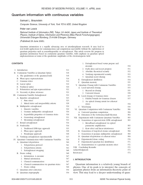
Quantum information with continuous variablesSamuel L.BraunsteinComputer Science,University of York,York YO105DD,United KingdomPeter van LoockNational Institute of Informatics(NII),Tokyo101-8430,Japan and Institute of TheoreticalPhysics,Institute of Optics,Information and Photonics(Max-Planck Forschungsgruppe),Universität Erlangen-Nürnberg,D-91058Erlangen,Germany͑Published29June2005͒Quantum information is a rapidly advancing area of interdisciplinary research.It may lead to real-world applications for communication and computation unavailable without the exploitation of quantum properties such as nonorthogonality or entanglement.This article reviews the progress in quantum information based on continuous quantum variables,with emphasis on quantum optical implementations in terms of the quadrature amplitudes of the electromagneticfield.CONTENTSI.Introduction513II.Continuous Variables in Quantum Optics516A.The quadratures of the quantizedfield516B.Phase-space representations518C.Gaussian states519D.Linear optics519E.Nonlinear optics520F.Polarization and spin representations522G.Necessity of phase reference523 III.Continuous-Variable Entanglement523A.Bipartite entanglement5251.Pure states5252.Mixed states and inseparability criteria526B.Multipartite entanglement5291.Discrete variables5292.Genuine multipartite entanglement5303.Separability properties of Gaussian states5304.Generating entanglement5315.Measuring entanglement533C.Bound entanglement534D.Nonlocality5341.Traditional EPR-type approach5352.Phase-space approach5363.Pseudospin approach536E.Verifying entanglement experimentally537 IV.Quantum Communication with Continuous Variables538A.Quantum teleportation5401.Teleportation protocol5412.Teleportation criteria5433.Entanglement swapping546B.Dense coding546rmation:A measure5472.Mutual information5473.Classical communication5474.Classical communication via quantum states5475.Dense coding548C.Quantum error correction550D.Quantum cryptography5501.Entanglement-based versus prepare andmeasure5502.Early ideas and recent progress5513.Absolute theoretical security5524.Verifying experimental security5535.Quantum secret sharing553E.Entanglement distillation554F.Quantum memory555V.Quantum Cloning with Continuous Variables555A.Local universal cloning5551.Beyond no-cloning5552.Universal cloners556B.Local cloning of Gaussian states5571.Fidelity bounds for Gaussian cloners5572.An optical cloning circuit for coherentstates558C.Telecloning559 VI.Quantum Computation with Continuous Variables560A.Universal quantum computation560B.Extension of the Gottesman-Knill theorem563 VII.Experiments with Continuous Quantum Variables565A.Generation of squeezed-state EPR entanglement5651.Broadband entanglement via opticalparametric amplification5652.Kerr effect and linear interference567B.Generation of long-lived atomic entanglement568C.Generation of genuine multipartite entanglement569D.Quantum teleportation of coherent states569E.Experimental dense coding570F.Experimental quantum key distribution571G.Demonstration of a quantum memory effect572 VIII.Concluding Remarks572 Acknowledgments573 References573I.INTRODUCTIONQuantum information is a relatively young branch of physics.One of its goals is to interpret the concepts of quantum physics from an information-theoretic point of view.This may lead to a deeper understanding of quan-REVIEWS OF MODERN PHYSICS,VOLUME77,APRIL20050034-6861/2005/77͑2͒/513͑65͒/$50.00©2005The American Physical Society513tum theory.Conversely,information and computation are intrinsically physical concepts,since they rely on physical systems in which information is stored and by means of which information is processed or transmitted. Hence physical concepts,and at a more fundamental level quantum physical concepts,must be incorporated in a theory of information and computation.Further-more,the exploitation of quantum effects may even prove beneficial for various kinds of information pro-cessing and communication.The most prominent ex-amples of this are quantum computation and quantum key distribution.Quantum computation means in par-ticular cases,in principle,computation faster than any known classical computation.Quantum key distribution makes possible,in principle,unconditionally secure communication as opposed to communication based on classical key distribution.From a conceptual point of view,it is illuminating to consider continuous quantum variables in quantum in-formation theory.This includes the extension of quan-tum communication protocols from discrete to continu-ous variables and hence fromfinite to infinite dimensions.For instance,the original discrete-variable quantum teleportation protocol for qubits and other finite-dimensional systems͑Bennett et al.,1993͒was soon after its publication translated into the continuous-variable setting͑Vaidman,1994͒.The main motivation for dealing with continuous variables in quantum infor-mation,however,originated in a more practical observa-tion:efficient implementation of the essential steps in quantum communication protocols,namely,preparing, unitarily manipulating,and measuring͑entangled͒quan-tum states,is achievable in quantum optics utilizing con-tinuous quadrature amplitudes of the quantized electro-magneticfield.For example,the tools for measuring a quadrature with near-unit efficiency or for displacing an optical mode in phase space are provided by homodyne-detection and feedforward techniques,respectively. Continuous-variable entanglement can be efficiently produced using squeezed light͓in which the squeezing of a quadrature’s quantumfluctuations is due to a non-linear optical interaction͑Walls and Milburn,1994͔͒and linear optics.A valuable feature of quantum optical implementa-tions based upon continuous variables,related to their high efficiency,is their unconditionalness.Quantum re-sources such as entangled states emerge from the non-linear optical interaction of a laser with a crystal͑supple-mented if necessary by some linear optics͒in an unconditional fashion,i.e.,every inverse bandwidth time.This unconditionalness is hard to obtain in discrete-variable qubit-based implementations using single-photon states.In that case,the desired prepara-tion due to the nonlinear optical interaction depends on particular͑coincidence͒measurement results ruling out the unwanted͑in particular,vacuum͒contributions in the outgoing state vector.However,the unconditional-ness of the continuous-variable implementations has its price:it is at the expense of the quality of the entangle-ment of the prepared states.This entanglement and hence any entanglement-based quantum protocol is al-ways imperfect,the degree of imperfection depending on the amount of squeezing of the laser light involved. Good quality and performance require large squeezing which is technologically demanding,but to a certain ex-tent͓about10dB͑Wu et al.,1986͔͒already state of the art.Of course,in continuous-variable protocols that do not rely on entanglement,for instance,coherent-state-based quantum key distribution,these imperfections do not occur.To summarize,in the most commonly used optical ap-proaches,the continuous-variable implementations al-ways work pretty well͑and hence efficiently and uncon-ditionally͒,but never perfectly.Their discrete-variable counterparts only work sometimes͑conditioned upon rare successful events͒,but they succeed,in principle, perfectly.A similar tradeoff occurs when optical quan-tum states are sent through noisy channels͑opticalfi-bers͒,for example,in a realistic quantum key distribu-tion scenario.Subject to losses,the continuous-variable states accumulate noise and emerge at the receiver as contaminated versions of the sender’s input states.The discrete-variable quantum information encoded in single-photon states is reliably conveyed for each photon that is not absorbed during transmission.Due to the recent results of Knill,Laflamme,and Mil-burn͑Knill et al.,2001͒,it is now known that efficient quantum information processing is possible,in principle, solely by means of linear optics.Their scheme is formu-lated in a discrete-variable setting in which the quantum information is encoded in single-photon states.Apart from entangled auxiliary photon states,generated off-line without restriction to linear optics,conditional dy-namics͑feedforward͒is the essential ingredient in mak-ing this approach work.Universal quantum gates such as a controlled-NOT gate can,in principle,be built using this scheme without need of any Kerr-type nonlinear op-tical interaction͑corresponding to an interaction Hamil-tonian quartic in the optical modes’annihilation and creation operators͒.This Kerr-type interaction would be hard to obtain on the level of single photons.However, the off-line generation of the complicated auxiliary states needed in the Knill-Laflamme-Milburn scheme seems impractical too.Similarly,in the continuous-variable setting,when it comes to more advanced quantum information proto-cols,such as universal quantum computation or,in a communication scenario,entanglement distillation,it turns out that tools more sophisticated than mere Gaussian operations are needed.In fact,the Gaussian operations are effectively those described by interaction Hamiltonians at most quadratic in the optical modes’annihilation and creation operators,thus leading to lin-ear input-output relations as in beam-splitter or squeez-ing transformations.Gaussian operations,mapping Gaussian states onto Gaussian states,also include ho-modyne detections and phase-space displacements.In contrast,the non-Gaussian operations required for ad-vanced continuous-variable quantum communication͑in particular,long-distance communication based on en-514S.L.Braunstein and P.van Loock:Quantum information with continuous variables Rev.Mod.Phys.,Vol.77,No.2,April2005tanglement distillation and swapping,quantum memory,and teleportation͒are due either to at least cubic non-linear optical interactions or to conditional transforma-tions depending on non-Gaussian measurements such asphoton counting.It seems that,at this very sophisticatedlevel,the difficulties and requirements of the discrete-and continuous-variable implementations are analogous.In this review,our aim is to highlight the strengths ofthe continuous-variable approaches to quantum infor-mation processing.Therefore we focus on those proto-cols that are based on Gaussian states and their feasiblemanipulation through Gaussian operations.This leads tocontinuous-variable proposals for the implementation ofthe simplest quantum communication protocols,such asquantum teleportation and quantum key distribution,and includes the efficient generation and detection ofcontinuous-variable entanglement.Before dealing with quantum communication andcomputation,in Sec.II,wefirst introduce continuousquantum variables within the framework of quantumoptics.The discussions about the quadratures of quan-tized electromagnetic modes,about phase-space repre-sentations,and about Gaussian states include the nota-tions and conventions that we use throughout thisarticle.We conclude Sec.II with a few remarks on linearand nonlinear optics,on alternative polarization andspin representations,and on the necessity of a phasereference in continuous-variable implementations.Thenotion of entanglement,indispensable in many quantumprotocols,is described in Sec.III in the context of con-tinuous variables.We discuss pure and mixed entangledstates,entanglement between two͑bipartite͒and be-tween many͑multipartite͒parties,and so-called bound ͑undistillable͒entanglement.The generation,measure-ment,and verification͑both theoretical and experimen-tal͒of continuous-variable entanglement are here of par-ticular interest.As for the properties of the continuous-variable entangled states related with theirinseparability,we explain how the nonlocal character ofthese states is revealed.This involves,for instance,vio-lations of Bell-type inequalities imposed by local real-ism.Such violations,however,cannot occur when themeasurements considered are exclusively of continuous-variable type.This is due to the strict positivity of theWigner function of the Gaussian continuous-variable en-tangled states,which allows for a hidden-variable de-scription in terms of the quadrature observables.In Sec.IV,we describe the conceptually and practi-cally most important quantum communication protocols formulated in terms of continuous variables and thus utilizing the continuous-variable͑entangled͒states. These schemes include quantum teleportation and en-tanglement swapping͑teleportation of entanglement͒, quantum͑super͒dense coding,quantum error correc-tion,quantum cryptography,and entanglement distilla-tion.Since quantum teleportation based on nonmaxi-mum continuous-variable entanglement,usingfinitely squeezed two-mode squeezed states,is always imperfect, teleportation criteria are needed both for the theoretical and for the experimental verification.As is known from classical communication,light,propagating at high speed and offering a broad range of different frequen-cies,is an ideal carrier for the transmission of informa-tion.This applies to quantum communication as well. However,light is less suited for the storage of informa-tion.In order to store quantum information,for in-stance,at the intermediate stations in a quantum re-peater,atoms are more appropriate media than light. Significantly,as another motivation to deal with continu-ous variables,a feasible light-atom interface can be built via free-space interaction of light with an atomic en-semble based on the alternative polarization and spin-type variables.No strong cavity QED coupling is needed as with single photons.The concepts of this transfer of quantum information from light to atoms and vice versa, as the essential ingredients of a quantum memory,are discussed in Sec.IV.FSection V is devoted to quantum cloning with con-tinuous variables.One of the most fundamental͑and historically one of thefirst͒“laws”of quantum informa-tion theory is the so-called no-cloning theorem͑Dieks, 1982;Wootters and Zurek,1982͒.It forbids the exact copying of arbitrary quantum states.However,arbitrary quantum states can be copied approximately,and the resemblance͑in mathematical terms,the overlap orfi-delity͒between the clones may attain an optimal value independent of the original states.Such optimal cloning can be accomplished locally by sending the original states͑together with some auxiliary system͒through a local unitary quantum circuit.Optimal cloning of Gauss-ian continuous-variable states appears to be more inter-esting than that of general continuous-variable states, because the latter can be mimicked by a simple coin toss.We describe a non-entanglement-based implemen-tation for the optimal local cloning of Gaussian continuous-variable states.In addition,for Gaussian continuous-variable states,an optical implementation exists of optimal cloning at a distance͑telecloning͒.In this case,the optimality requires entanglement.The cor-responding multiparty entanglement is again producible with nonlinear optics͑squeezed light͒and linear optics ͑beam splitters͒.Quantum computation over continuous variables,dis-cussed in Sec.VI,is a more subtle issue than the in some sense straightforward continuous-variable extensions of quantum communication protocols.Atfirst sight,con-tinuous variables do not appear well suited for the pro-cessing of digital information in a computation.On the other hand,a continuous-variable quantum state having an infinite-dimensional spectrum of eigenstates contains a vast amount of quantum information.Hence it might be promising to adjust the continuous-variable states theoretically to the task of computation͑for instance,by discretization͒and yet to exploit their continuous-variable character experimentally in efficient͑optical͒implementations.We explain in Sec.VI why universal quantum computation over continuous variables re-quires Hamiltonians at least cubic in the position and momentum͑quadrature͒operators.Similarly,any quan-tum circuit that consists exclusively of unitary gates from515S.L.Braunstein and P.van Loock:Quantum information with continuous variables Rev.Mod.Phys.,Vol.77,No.2,April2005the continuous-variable Clifford group can be efficientlysimulated by purely classical means.This is acontinuous-variable extension of the discrete-variableGottesman-Knill theorem in which the Clifford groupelements include gates such as the Hadamard͑in thecontinuous-variable case,Fourier͒transform or the con-trolled NOT͑CNOT͒.The theorem applies,for example,to quantum teleportation which is fully describable by CNOT’s and Hadamard͑or Fourier͒transforms of some eigenstates supplemented by measurements in thateigenbasis and spin or phaseflip operations͑or phase-space displacements͒.Before some concluding remarks in Sec.VIII,wepresent some of the experimental approaches to squeez-ing of light and squeezed-state entanglement generationin Sec.VII.A.Both quadratic and quartic optical nonlin-earities are suitable for this,namely,parametric downconversion and the Kerr effect,respectively.Quantumteleportation experiments that have been performed al-ready based on continuous-variable squeezed-state en-tanglement are described in Sec.VII.D.In Sec.VII,wefurther discuss experiments with long-lived atomic en-tanglement,with genuine multipartite entanglement ofoptical modes,experimental dense coding,experimentalquantum key distribution,and the demonstration of aquantum memory effect.II.CONTINUOUS VARIABLES IN QUANTUM OPTICSFor the transition from classical to quantum mechan-ics,the position and momentum observables of the par-ticles turn into noncommuting Hermitian operators inthe Hamiltonian.In quantum optics,the quantized elec-tromagnetic modes correspond to quantum harmonicoscillators.The modes’quadratures play the roles of theoscillators’position and momentum operators obeyingan analogous Heisenberg uncertainty relation.A.The quadratures of the quantizedfieldFrom the Hamiltonian of a quantum harmonic oscil-lator expressed in terms of͑dimensionless͒creation and annihilation operators and representing a single mode k, Hˆk=បk͑aˆk†aˆk+12͒,we obtain the well-known form writ-ten in terms of“position”and“momentum”operators ͑unit mass͒,Hˆk=12͑pˆk2+k2xˆk2͒,͑1͒withaˆk=1ͱ2បk͑k xˆk+ipˆk͒,͑2͒aˆk†=1ͱ2បk͑k xˆk−ipˆk͒,͑3͒or,conversely,xˆk=ͱប2k͑aˆk+aˆk†͒,͑4͒pˆk=−iͱបk2͑aˆk−aˆk†͒.͑5͒Here,we have used the well-known commutation rela-tion for position and momentum,͓xˆk,pˆkЈ͔=iប␦kkЈ,͑6͒which is consistent with the bosonic commutation rela-tions͓aˆk,aˆkЈ†͔=␦kkЈ,͓aˆk,aˆkЈ͔=0.In Eq.͑2͒,we see that up to normalization factors the position and the momentum are the real and imaginary parts of the annihilation op-erator.Let us now define the dimensionless pair of con-jugate variables,Xˆkϵͱk2បxˆk=Re aˆk,Pˆkϵ1ͱ2បk pˆk=Im aˆk.͑7͒Their commutation relation is then͓Xˆk,PˆkЈ͔=i2␦kkЈ.͑8͒In other words,the dimensionless position and momen-tum operators,Xˆk and Pˆk,are defined as if we setប=1/2.These operators represent the quadratures of a single mode k,in classical terms corresponding to the real and imaginary parts of the oscillator’s complex am-plitude.In the following,by using͑Xˆ,Pˆ͒or equivalently ͑xˆ,pˆ͒,we shall always refer to these dimensionless quadratures as playing the roles of position and momen-tum.Hence͑xˆ,pˆ͒will also stand for a conjugate pair of dimensionless quadratures.The Heisenberg uncertainty relation,expressed in terms of the variances of two arbitrary noncommuting observables Aˆand Bˆfor an arbitrary given quantum state,͗͑⌬Aˆ͒2͘ϵŠ͑Aˆ−͗Aˆ͒͘2‹=͗Aˆ2͘−͗Aˆ͘2,͗͑⌬Bˆ͒2͘ϵŠ͑Bˆ−͗Bˆ͒͘2‹=͗Bˆ2͘−͗Bˆ͘2,͑9͒becomes͗͑⌬Aˆ͒2͗͑͘⌬Bˆ͒2͘ജ14͉͓͗Aˆ,Bˆ͔͉͘2.͑10͒Inserting Eq.͑8͒into Eq.͑10͒yields the uncertainty re-lation for a pair of conjugate quadrature observables of a single mode k,xˆk=͑aˆk+aˆk†͒/2,pˆk=͑aˆk−aˆk†͒/2i,͑11͒namely,͗͑⌬xˆk͒2͗͑͘⌬pˆk͒2͘ജ14͉͓͗xˆk,pˆk͔͉͘2=116.͑12͒Thus,in our units,the quadrature variance for a vacuum or coherent state of a single mode is1/4.Let us further516S.L.Braunstein and P.van Loock:Quantum information with continuous variables Rev.Mod.Phys.,Vol.77,No.2,April2005illuminate the meaning of the quadratures by looking at a single frequency mode of the electric field ͑for a single polarization ͒,E ˆk ͑r ,t ͒=E 0͓a ˆk ei ͑k ·r −k t ͒+a ˆk †e −i ͑k ·r −k t ͔͒.͑13͒The constant E 0contains all the dimensional prefactors.By using Eq.͑11͒,we can rewrite the mode asE ˆk ͑r ,t ͒=2E 0͓x ˆk cos ͑k t −k ·r ͒+pˆk sin ͑k t −k ·r ͔͒.͑14͒Clearly,the position and momentum operators xˆk and p ˆk represent the in-phase and out-of-phase components of the electric-field amplitude of the single mode k with respect to a ͑classical ͒reference wave ϰcos ͑k t −k ·r ͒.The choice of the phase of this wave is arbitrary,of course,and a more general reference wave would lead us to the single-mode descriptionE ˆk ͑r ,t ͒=2E 0͓x ˆk ͑⌰͒cos ͑k t −k ·r −⌰͒+pˆk ͑⌰͒sin ͑k t −k ·r −⌰͔͒,͑15͒with the more general quadraturesxˆk ͑⌰͒=͑a ˆk e −i ⌰+a ˆk †e +i ⌰͒/2,͑16͒p ˆk ͑⌰͒=͑a ˆk e −i ⌰−a ˆk †e +i ⌰͒/2i .͑17͒These new quadratures can be obtained from x ˆk and p ˆk via the rotationͩx ˆk ͑⌰͒pˆk ͑⌰͒ͪ=ͩcos ⌰sin ⌰−sin ⌰cos ⌰ͪͩxˆk pˆk ͪ.͑18͒Since this is a unitary transformation,we again end upwith a pair of conjugate observables fulfilling the com-mutation relation ͑8͒.Furthermore,because pˆk ͑⌰͒=x ˆk ͑⌰+/2͒,the whole continuum of quadratures is cov-ered by x ˆk ͑⌰͒with ⌰͓0,͒.This continuum of observ-ables is indeed measurable by relatively simple means.Such a so-called homodyne detection works as follows.A photodetector measuring an electromagnetic mode converts the photons into electrons and hence into an electric current,called the photocurrent i ˆ.It is therefore sensible to assume i ˆϰn ˆ=a ˆ†a ˆor i ˆ=qaˆ†a ˆwhere q is a con-stant ͑Paul,1995͒.In order to detect a quadrature of themode aˆ,the mode must be combined with an intense local oscillator at a 50:50beam splitter.The local oscil-lator is assumed to be in a coherent state with large photon number,͉␣LO ͘.It is therefore reasonable to de-scribe this oscillator by a classical complex amplitude␣LO rather than by an annihilation operator aˆLO .The two output modes of the beam splitter,͑aˆLO +a ˆ͒/ͱ2and ͑a ˆLO −a ˆ͒/ͱ2͑see Sec.II.D ͒,may then be approximated byaˆ1=͑␣LO +a ˆ͒/ͱ2,aˆ2=͑␣LO −a ˆ͒/ͱ2.͑19͒This yields the photocurrentsi ˆ1=qa ˆ1†aˆ1=q ͑␣LO *+a ˆ†͒͑␣LO +a ˆ͒/2,i ˆ2=qa ˆ2†aˆ2=q ͑␣LO *−a ˆ†͒͑␣LO −a ˆ͒/2.͑20͒The actual quantity to be measured will be the differ-ence photocurrent␦i ˆϵi ˆ1−i ˆ2=q ͑␣LO *aˆ+␣LO a ˆ†͒.͑21͒By introducing the phase ⌰of the local oscillator,␣LO=͉␣LO ͉exp ͑i ⌰͒,we recognize that the quadrature observ-able xˆ͑⌰͒from Eq.͑16͒is measured ͑without mode index k ͒.Now adjustment of the local oscillator’s phase ⌰͓0,͔enables us to detect any quadrature from thewhole continuum of quadratures xˆ͑⌰͒.A possible way to realize quantum tomography ͑Leonhardt,1997͒,i.e.,the reconstruction of the mode’s quantum state given by its Wigner function,relies on this measurement method,called ͑balanced ͒homodyne detection .A broadband rather than a single-mode description of homodyne de-tection can be found in the work of Braunstein and Crouch ͑1991͒,who also investigate the influence of a quantized local oscillator.We have now seen that it is not too hard to measure the quadratures of an electromagnetic mode.Unitary transformations such as quadrature displacements ͑phase-space displacements ͒can also be relatively easily performed via the so-called feedforward technique,as opposed to,for example,photon number displacements.This simplicity and the high efficiency when measuring and manipulating continuous quadratures are the main reasons why continuous-variable schemes appear more attractive than those based on discrete variables such as the photon number.In the following,we shall refer mainly to the conju-gate pair of quadratures xˆk and p ˆk ͑position and momen-tum,i.e.,⌰=0and ⌰=/2͒.In terms of these quadra-tures,the number operator becomesn ˆk =a ˆk †a ˆk =x ˆk 2+p ˆk 2−12,͑22͒using Eq.͑8͒.Let us finally review some useful formulas for the single-mode quadrature eigenstates,xˆ͉x ͘=x ͉x ͘,pˆ͉p ͘=p ͉p ͘,͑23͒where we have now dropped the mode index k .They are orthogonal,͗x ͉x Ј͘=␦͑x −x Ј͒,͗p ͉p Ј͘=␦͑p −p Ј͒,͑24͒and complete,͵−ϱϱ͉x ͗͘x ͉dx =1,͵−ϱϱ͉p ͗͘p ͉dp =1.͑25͒Just as for position and momentum eigenstates,the quadrature eigenstates are mutually related to each other by a Fourier transformation,͉x ͘=1ͱ͵−ϱϱe −2ixp ͉p ͘dp ,͑26͒517S.L.Braunstein and P .van Loock:Quantum information with continuous variablesRev.Mod.Phys.,Vol.77,No.2,April 2005͉p͘=1ͱ͵−ϱϱe+2ixp͉x͘dx.͑27͒Despite being unphysical and not square integrable,the quadrature eigenstates can be very useful in calculations involving the wave functions͑x͒=͗x͉͘,etc.,and inidealized quantum communication protocols based on continuous variables.For instance,a vacuum state infi-nitely squeezed in position may be expressed by a zero-position eigenstate͉x=0͘=͉͐p͘dp/ͱ.The physical,fi-nitely squeezed states are characterized by the quadrature probability distributions͉͑x͉͒2,etc.,ofwhich the widths correspond to the quadrature uncer-tainties.B.Phase-space representationsThe Wigner function is particularly suitable as a “quantum phase-space distribution”for describing the effects on the quadrature observables that may arise from quantum theory and classical statistics.It behaves partly as a classical probability distribution,thus en-abling us to calculate measurable quantities such as mean values and variances of the quadratures in a classical-like fashion.On the other hand,in contrast to a classical probability distribution,the Wigner function can become negative.The Wigner function was originally proposed by Wigner in his1932paper“On the quantum correction for thermodynamic equilibrium”͑Wigner,1932͒.There, he gave an expression for the Wigner function in terms of the position basis which reads͑with x and p being a dimensionless pair of quadratures in our units withប=1/2as introduced in the previous section;Wigner, 1932͒W͑x,p͒=2͵dye+4iyp͗x−y͉ˆ͉x+y͘.͑28͒Here and throughout,unless otherwise specified,the in-tegration will be over the entire space of the integration variable͑i.e.,here the integration goes from−ϱtoϱ͒. We gave Wigner’s original formula for only one mode or one particle͓Wigner’s͑1932͒original equation was in N-particle form͔because it simplifies the understanding of the concept behind the Wigner function approach. The extension to N modes is straightforward.Why does W͑x,p͒resemble a classical-like probability distribution?The most important attributes that explain this are the proper normalization,͵W͑␣͒d2␣=1,͑29͒the property of yielding the correct marginal distribu-tions,͵W͑x,p͒dx=͗p͉ˆ͉p͘,͵W͑x,p͒dp=͗x͉ˆ͉x͘,͑30͒and the equivalence to a probability distribution in clas-sical averaging when mean values of a certain class of operators Aˆin a quantum stateˆare to be calculated,͗Aˆ͘=Tr͑ˆAˆ͒=͵W͑␣͒A͑␣͒d2␣,͑31͒with a function A͑␣͒related to the operator Aˆ.The measure of integration is in our case d2␣=d͑Re␣͒d͑Im␣͒=dxdp with W͑␣=x+ip͒ϵW͑x,p͒,and we shall use d2␣and dxdp interchangeably.The opera-tor Aˆrepresents a particular class of functions of aˆand aˆ†or xˆand pˆ.The marginal distribution for p,͗p͉ˆ͉p͘,is obtained by changing the integration variables͑x−y =u,x+y=v͒and using Eq.͑26͒,that for x,͗x͉ˆ͉x͘,by using͐exp͑+4iyp͒dp=͑/2͒␦͑y͒.The normalization of the Wigner function then follows from Tr͑ˆ͒=1.For any symmetrized operator͑Leonhardt,1997͒,the so-called Weyl correspondence͑Weyl,1950͒,Tr͓ˆS͑xˆn pˆm͔͒=͵W͑x,p͒x n p m dxdp,͑32͒provides a rule for calculating quantum-mechanical ex-pectation values in a classical-like fashion according to Eq.͑31͒.Here,S͑xˆn pˆm͒indicates symmetrization.For example,S͑xˆ2pˆ͒=͑xˆ2pˆ+xˆpˆxˆ+pˆxˆ2͒/3corresponds to x2p ͑Leonhardt,1997͒.Such a classical-like formulation of quantum optics in terms of quasiprobability distributions is not unique.In fact,there is a whole family of distributions P͑␣,s͒of which each member corresponds to a particular value of a real parameter s,P͑␣,s͒=12͵͑,s͒exp͑i␣*+i*␣͒d2,͑33͒with the s-parametrized characteristic functions ͑,s͒=Tr͓ˆexp͑−iaˆ†−i*aˆ͔͒exp͑s͉͉2/2͒.͑34͒The mean values of operators normally and antinor-mally ordered in aˆand aˆ†may be calculated via the so-called P function͑s=1͒and Q function͑s=−1͒,re-spectively.The Wigner function͑s=0͒and its character-istic function͑,0͒are perfectly suited to provide ex-pectation values of quantities symmetric in aˆand aˆ†such as the quadratures.Hence the Wigner function,though not always positive definite,appears to be a good com-promise in describing quantum states in terms of quan-tum phase-space variables such as single-mode quadra-tures.We may formulate various quantum states relevant to continuous-variable quantum communica-tion by means of the Wigner representation.These par-ticular quantum states exhibit extremely nonclassical features such as entanglement and nonlocality.Yet their Wigner functions are positive definite,and thus belong to the class of Gaussian states.518S.L.Braunstein and P.van Loock:Quantum information with continuous variables Rev.Mod.Phys.,Vol.77,No.2,April2005。
军用光电系统作用距离分析

第37卷,增刊 红外与激光工程 2008年6月 V ol.37 Supplement Infrared and Laser Engineering Jun. 2008收稿日期:2008-06-19作者简介:赵妙娟(1954-),女,河南洛阳人,研究员,主要从事光电系统总体及光学设计技术研究。
Email: zhmiaojuan@军用光电系统作用距离分析赵妙娟,车 宏(中航一集团第六一三研究所,河南 洛阳 471009)摘要:军用光电探测系统非常重要的性能指标是作用距离。
分析系统作用距离的目的是找出目标源、大气和传感器性能三者之间的定量关系。
当使用要求的考核条件确定时,进行分析、协调、折衷并合理选择系统其它的设计参数,有利实现传感器的最佳系统性能。
文章结合机载综合光电探测系统典型使用要求,对红外、激光、电视各光电传感分系统的作用距离进行了分析,进而定量计算了特定条件下的作用距离。
关键词:作用距离; 机载综合光电探测系统; 红外/激光/电视中图分类号:TN2 文献标识码:A 文章编号:1007-2276(2008)增(红外)-0501-03Analysis of the efficient distance of O-E system for militaryZHAO Miao-juan, CHE Hong(No.613 Research Institute of China Aeronautical Industry, Luoyang 471009, China)Abstract: The efficient distance is a very important system indicator of the optical-electronic detector. When the examination conditions are identified, the system efficient distance was analyzed in order to find the quantitive-relation among the object, the atmosphere and the transducer characters. Thus the other design indicators of the system were coordinated and selected, so as to realize the best characters of the transducer system. The thesis took the synthetic optical-electronic detector on aeroplanes for example, the efficient distance of infrared, laser and television sub-transducer systems was analyzed, and the efficient distance in certain conditions was calculated quantitively.Key words: Efficient distance; Synthetic optical-electronic System on aeroplane;Infrared/laser/television0 引 言军用光电探测系统通常包括激光、电视、红外等传感器。
Semiconductor Optoelectronics 1-Semiconductor Review

K q, e m0 µ0 ε0 h
c
1.38 x 10⁻²³ Joule/Kelvin 8.62 x 10⁻⁵ eV/Kelvin 1.6 x 10⁻¹⁹ Coulomb 9.11 x 10⁻³¹ kilogram 4π x 10-7 Henry/meter 8.854 x 10⁻¹² Farad/meter 6.626 x 10⁻³⁴ Joule second 2.998 x 10⁸ meter/second
3
Text Book
� Larry A. Coldren, Scott W. Corzine ,Diode Lasers and Photonic Integrated Circuits. 《二极管激光器和集成光路》,史寒星译, 北京邮电大学出版社,2006年 Reference book :Fundamentals of Photonics, Bahaa E. A. Saleh ,Chap. 15-17.
Notes
Ref.Book Chap. 15; Chapter 1, Appendix 1 Ref.Book Chap. 16; Chapter 2,4 Chapter 2,5 Chapter 3,6 Chapter 8; Lecture Notes Ref. Book Chap.17 Lecture Notes Lecture Notes Lecture Notes
6
1.半导体物理基础回顾 Review of Semiconductor Physics
7
Outline
1. Energy Bands and Charge Carriers - The basics of quantum mechanics - Energy levels and bands - Effective mass 2. Electroቤተ መጻሕፍቲ ባይዱ and Hole Concentrations - Density of states - Probability of occupancy & Fermi level - Intrinsic and Doped Semiconductors 3. p-n Junction
让光盘成为一种习惯 用英语作文

让光盘成为一种习惯用英语作文Make Discs a Habit.In the realm of digital storage, the humble optical disc has often been overshadowed by its more modern counterparts, such as flash drives and cloud storage. However, despite the technological advancements, optical discs continue to offer several advantages that make them a valuable tool in various scenarios.Durability and Longevity.One of the primary benefits of optical discs is their exceptional durability. Unlike magnetic or solid-state storage devices, which can be susceptible to data loss due to physical damage or electromagnetic interference, optical discs are remarkably resilient. The data stored on optical discs is physically etched into the disc's surface, making it highly resistant to scratches, dust, and other environmental factors. Additionally, optical discs have along lifespan, with some discs boasting a potentiallifespan of over 100 years. This makes them an ideal choice for long-term data archiving and preservation.Large Storage Capacity.Another advantage of optical discs is their ample storage capacity. The most common type of optical disc, the DVD, can store up to 4.7 gigabytes (GB) of data, while Blu-ray discs can store up to 25GB or even 100GB. This makes optical discs a suitable option for storing large files, such as high-resolution videos, music libraries, or data backups. By using multiple discs, it is possible to create a sizeable and affordable storage solution.Wide Compatibility.Optical discs enjoy widespread compatibility across a range of devices. DVD and Blu-ray players are commonly found in home entertainment systems, personal computers, and laptops. As a result, accessing and playing content stored on optical discs is generally straightforward andconvenient. This compatibility makes optical discs an excellent choice for sharing data or distributing content, as recipients are likely to have the necessary hardware to use the discs.Cost-Effectiveness.Compared to other storage options, such as solid-state drives (SSDs) or cloud storage services, optical discsoffer a cost-effective solution for storing large amounts of data. Optical discs are relatively inexpensive to produce and purchase, making them a budget-friendly option for individuals and organizations looking to archive or distribute data. The large storage capacity of optical discs further enhances their cost-effectiveness by enabling users to store a considerable amount of data on a single disc.Applications.Optical discs have a wide range of applications, including:Data backup and archiving: Optical discs provide a reliable and cost-effective method for backing up and archiving important files, such as financial records, legal documents, and family photos. The durability and longevity of optical discs ensure that data is preserved for extended periods.Content distribution: Optical discs are commonly used to distribute movies, music, software, and other digital content. The large storage capacity and wide compatibility of optical discs make them a suitable format fordistributing large files quickly and easily.Home entertainment: DVDs and Blu-ray discs are the primary formats used for distributing and playing movies and TV shows in the home entertainment market. Optical discs offer high-quality audio and video playback, making them an enjoyable way to enjoy media content.Educational resources: Optical discs are often used in educational settings to distribute educational software,videos, and other materials. The durability and cost-effectiveness of optical discs make them a practical solution for schools and universities.Conclusion.In an era dominated by digital technologies, optical discs remain a valuable storage medium due to their durability, large storage capacity, wide compatibility, and cost-effectiveness. Whether for data backup, content distribution, home entertainment, or educational purposes, optical discs continue to offer a practical and reliable solution for storing and accessing information. By making optical discs a habit, individuals and organizations can effectively manage their data needs while enjoying the benefits of this proven technology.。
光学显微镜应用:暗场照明

Optical Microscopy Application: Darkfield IlluminationDarkfield illumination is a technique in optical microscopy that eliminates scattered light from the sample image。
This yields an image with a dark background around the specimen,and is essentially the complete opposite of the brightfield illumination technique。
The primary imaging goal of the darkfield illumination technique is to enhance the contrast of an unstained sample,which is incredibly powerful,yet simple, for live cellular analysis or samples that have not gone through the staining process. IMAGE APPEARANCEA typical darkfield illumination image has a white/bright specimen with a dark background and environment filling the image。
This is the exact opposite of a brightfield illumination image, and is useful for unstained specimens or images that require increased contrast. The advantage with using darkfield illumination is that unstained specimens can remain alive and vital, whereas their brightfield counterparts must be treated and are no longer active. Also,it is possible to acquire more qualitative results with this technique through live cellular analysis。
Optical Communications

Optical CommunicationsOptical communication is a crucial aspect of modern technology, playing a significant role in various industries such as telecommunications, healthcare, and defense. The use of light to transmit data offers numerous advantages over traditional methods, including higher bandwidth, lower latency, and increased security. As our reliance on digital communication continues to grow, the importance of optical communication cannot be overstated. One of the key benefits of optical communication is its ability to transmit data at incredibly high speeds. By using light to carry information, optical communication systems can achievedata rates that far surpass those of traditional copper-based systems. This high bandwidth is essential for meeting the ever-increasing demands of modern applications, such as streaming video, cloud computing, and virtual reality. In addition to speed, optical communication also offers lower latency compared to other forms of communication. Light travels much faster than electrical signals, allowing data to be transmitted across long distances in a fraction of the time. This low latency is critical for real-time applications like online gaming, video conferencing, and financial trading, where even the slightest delay can have significant consequences. Furthermore, optical communication provides enhanced security for data transmission. Unlike electrical signals, light is not easily intercepted or tampered with, making optical communication systems less vulnerable to hacking or eavesdropping. This increased level of security is particularly important for industries that handle sensitive information, such as government agencies, financial institutions, and healthcare providers. Moreover, optical communication is also more reliable than traditional communication methods. Light signals are less susceptible to interference from external sources, such as electromagnetic radiation or radio frequency signals, ensuring a more stable and consistent data transmission. This reliability is essential for maintaining seamless communication networks in critical infrastructure, such as power grids, transportation systems, and emergency services. From a sustainability perspective, optical communication offers energy efficiency benefits compared to traditional communication systems. Light-based technologies consume less power than their electrical counterparts, resulting in lower energy costs and reduced environmentalimpact. As the global demand for data continues to rise, the energy efficiency of optical communication will play a significant role in reducing carbon emissions and mitigating climate change. In conclusion, optical communication is a vital technology that underpins the modern digital world. Its high-speed data transmission, low latency, enhanced security, reliability, and energy efficiency make it indispensable for a wide range of applications. As we continue to rely on digital communication for work, education, entertainment, and social interaction, the importance of optical communication will only continue to grow. By investing in optical communication infrastructure and research, we can ensure a more connected, secure, and sustainable future for generations to come.。
- 1、下载文档前请自行甄别文档内容的完整性,平台不提供额外的编辑、内容补充、找答案等附加服务。
- 2、"仅部分预览"的文档,不可在线预览部分如存在完整性等问题,可反馈申请退款(可完整预览的文档不适用该条件!)。
- 3、如文档侵犯您的权益,请联系客服反馈,我们会尽快为您处理(人工客服工作时间:9:00-18:30)。
1
2
Wang & Chakrabarty
Table 1. Radio-Quiet Neutron Stars
Source
SNR
d
Age kTbb
(kpc) (103 yr) (keV)
Refs
1E 0820–4247 Pup A
2.0
3.7 0.28
1-3
1E 1614–5055 RCW 103
3.3
Abstract. We report on our search for the optical counterparts of the Southern Hemisphere anomalous X-ray pulsar 1E1048.1-5937 and the radio-quiet neutron stars in supernova remnants Puppis A, RCW 103, and PKS 1209-52. The observations were carried out with the new MIT/CfA MagIC camera on the Magellan-I 6.5 m telescope in Chile. We present deep multiband optical images of the X-ray error circles for each of these targets and discuss the resulting candidates and limits.
(8) Bignami, Caraveo, & Mereghetti 1992. (9) Mereghetti, Bignami, & Caraveo 1996.
filter set, which have the following central wavelengths (Fukugita et al. 1996): u′=3540 ˚A; g′=4770 ˚A; r′=6230 ˚A; i′=7620 ˚A; and z′=9130 ˚A.
3
Figure 1. (a) Magellan MagIC image of Puppis A (1E 0820–4247) region in i′ band. The X-ray source position, derived from the Chandra/ACIS observation, is indicated as a 1′′ diameter circle. (b) Magellan MagIC image of PKS 1209–52 (1E 1207–5209) region in i′ band. A 5′′ circle indicates the X-ray source position given by Einstein/HRI observation (Seward 1990). Two parallel dotted lines with the width of 1′′.4 between them, which cross the HRI error circle, are drawn to indicate the position derived from Chandra/ACIS observation.
arXiv:astro-ph/0112125v1 5 Dec 2001
Neutron Stars in Supernova Remnants ASP Conference Series, Vol. 9999, 2002 P. O. Slane and B. M. Gaensler, eds.
Search for the Optical Counterparts of Southern Anomalous X-Ray Pulsars and Radio-Quiet Neutron Stars in Young Supernova Remnants
2. Observations
Our observations were made using the Magellan Instant Camera (MagIC) on the Magellan-1/Walter Baade 6.5-meter telescope at Las Campanas Observatory, Chile. MagIC is a CCD filter photometer built by MIT and CfA for the f /11 focus of the Baade telescope. The current detector is a 2048×2048 SITe CCD with a 69 mas/pixel scale and a 142×142 arcsec field of view. We used the Sloan
r′
i′
z′
A > 25.6 23.20 ±0.15 21.56 ±0.04
B 25.6± 0.3 22.22± 0.14 20.36± 0.02
C 23.8± 0.1 21.48±0.13 19.94± 0.02
Search for the Optical Counterparts of AXPs and RQNSs
1-3 0.56
4-6
1E 1207–5209 PKS 1209–52 1.5
7
0.25
7-9
References. – (1) Petre et al. 1982. (2) Petre, Becker, & Winkler 1996. (3) Pavlov et al. 1999.
(4) Tuohy & Garmire 1980. (5) Caswell et al. 1975. (6) Gotthelf, Petre, & Hwang 1997. (7) Helfand & Becker 1984.
Table 2. Magellan Observations
Exposure Time (min)
Source
Date
u′ g′ r′ i′ z′
1E 1048.1–5937 2001 Mar 24 ... ... 10 10 10
1E 1207–5209 2001 Mar 24 ... 10 9 10 10
1. Background
The anomalous X-ray pulsars (AXPs) are a group of X-ray pulsars whose spin periods fall in a narrow range (∼ 6 − 12 s), whose X-ray spectra are very soft, and which show no evidence that they accrete from a binary companion (see Mereghetti 1999 for a recent review). These objects may be isolated neutron stars with extremely strong (∼ 1014 G) surface magnetic fields, or they may be accreting from a “fallback” accretion disk. Optical measurements could potentially help discriminate between these models. An optical counterpart to one AXP, 4U 0142+61, has recently been identified and shown to have peculiar optical colors (Hulleman et al. 2000). The radio-quiet neutron stars (RQNSs) are a group of compact X-ray sources found near the center of young supernova remnants. Their X-ray spectra are roughly consistent with young, cooling neutron stars, but they show no evidence for the non-thermal emission associated with “classical” young pulsars like the Crab (see Brazier & Johnston 1999 for a review). The X-ray spectral properties of the RQNSs and the AXPs are similar (see, e.g., Chakrabarty et al. 2001). Below in Table 1, the general properties of the three RQNSs as our targets in the southern sky are listed.
2001 Jun 12 5 ... ... ... ...
1E 0820–4247 2001 Mar 25 ... ... 10 10 6
1E 1614–5055 2001 Mar 25 ... ... 10 10 10
3. Results