ASMT-MY00-NHJ00中文资料
CDMA系统NAM参数介绍
CDMA系统NAM参数介绍国际移动⽤户识别码(IMSI)与移动台识别码(MIN):IMSI 是在CDMA 数字公⽤陆地蜂窝移动通信⽹中唯⼀地识别⼀个移动⽤户的号码。
这个号码应当被写⼊移动台/UIM 卡中。
本体制使⽤基于MIN 的IMSI (MIN based IMSI )。
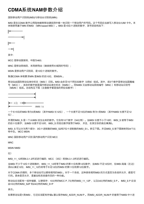
IMSI 是15位⼗进制的数字,其号码结构如下:其中:MCC 是移动国家码,中国为460;MNC 是移动⽹络码,本⽹使⽤03(继续使⽤长城⽹的号码);MSIN 是移动⽤户识别码,是10位⼗进制的数字。
联通CDMA 体制要求MIN 是IMSI 的后10位,即MSIN 。
移动站由国际移动站⾝份标志(IMSI )识别。
IMSI 由多⾄15个阿拉伯数字(0到9)组成。
其中,前3个数字是移动站国籍编号(MCC ),其余的数字就是国内移动站⾝份标志(NMSI )。
⽽NMSI ⼜由移动站⽹络编号(MNC )和移动站识别号(MSIN )组成。
总结构见下图(注意数字都是指的阿拉伯数字):⼀个长15位的IMSI 称为0类IMSI (其中NMSI 长12位),⼀个长度不⾜15位的IMSI 称为1类IMSI (其中NMSI 长度不⾜12位),所谓的IMSI_S 是⼀个从IMSI 派⽣出来的数字。
它含有10个数字(34⽐特)。
当IMSI 长度不⼩于10时,IMSI_S 就等于IMSI 的后⼗位数字;当IMSI 长度不⾜10时,IMSI_S 的低位数字就等于IMSI ,并且,在其空余的⾼位填满0。
IMSI_S 可以分为两个部分:3位⼗进制数的IMSI_S2和7位⼗进制数的IMSI_S1。
参见下图。
并且IMSI_S 按下图映射到34个⽐特中去。
MCC MSINMNC 国际移动⽤户识别国内移动⽤户识别 MCCMNCMSIN NMSI位)IMSI_11_12将按6.3.1.2所述进⾏编码;MCC (3位)将按6.3.1.3所述进⾏编码。
当IMSI 不少于12位⼗进制数时,IMSI_11_12将等于IMSI 的第11位和第12位数字;当IMSI 不⾜12位时,在IMSI ⾼端(左边)添0以凑⾜12位,IMSI_11_12仍将等于补⾜12位的IMSI 的第11位和第12位数字。
STM8S103中文资料

10 电气特性 .................................................................................................................32
10.1 参数条件............................................................................................................................32 10.1.1 最小和最大值 .............................................................................................................32 10.1.2 典型数值 ....................................................................................................................32 10.1.3 典型曲线 ....................................................................................................................32 10.1.4 负载电容 ....................................................................................................................32 10.1.5 引脚输入电压 .............................................................................................................32
TM100SZ-M中文资料

ABSOLUTE MAXIMUM RATINGSUnit V V V V V VNON-INSULATED TYPEM 400480320400480320Symbol V RRM V RSM V R (DC)V DRM V DSM V D (DC)ParameterRepetitive peak reverse voltage Non-repetitive peak reverse voltage DC reverse voltageRepetitive peak off-state voltage Non-repetitive peak off-state voltage DC off-state voltageUnit A A A A 2s A/µs W W V V A °C °C N·m kg·cm N·m kg·cm gConditionsThree-phase, half-wave, T C =122°C One half cycle at 60Hz, peak value Value for one cycle of surge current V D =1/2V DRM , I G =1.0A, T j =150°CMain terminal screw M5Mounting screw M6Typical valueRatings 155********.7 × 104505.00.5105.02.0–40~+150–40~+1251.47~1.9615~201.96~2.9420~30160Symbol I T (RMS)I T (AV)I TSM I 2t di/dt P GM P G (AV)V FGM V RGM I FGM T j T stg——ParameterRMS on-state current Average on-state currentSurge (non-repetitive) on-state current I 2t for fusingCritical rate of rise of on-state current Peak gate power dissipation Average gate power dissipation Peak gate forward voltage Peak gate reverse voltage Peak gate forward current Junction temperature Storage temperatureMounting torqueWeight Voltage classELECTRICAL CHARACTERISTICSUnit mA mA V V/µs V V mA °C/W °C/WLimitsSymbol I RRM I DRM V TM dv/dt V GT V GD I GT R th (j-c)R th (c-f)ParameterRepetitive peak reverse current Repetitive peak off-state current On-state voltageCritical rate of rise of off-state voltage Gate trigger voltage Gate non-trigger voltage Gate trigger current Thermal resistance Contact thermal resistanceTest conditionsT j =150°C, V RRM applied T j =150°C, V DRM appliedT j =150°C, I TM =300A, instantaneous meas.T j =150°C, V D =2/3V DRM T j =25°C, V D =6V, R L =2ΩT j =150°C, V D =1/2V DRM T j =25°C, V D =6V, R L =2ΩJunction to case (per 1/3 module)Case to fin, conductive grease applied (per 1/3 module)Min.———200—0.2515——Typ.—————————Max.30301.15—3.0—1000.20.3NON-INSULATED TYPENON-INSULATED TYPE。
ASM说明书
3.3.5 Output Indexer Home
3.3.6 Output Track End
3.3.7 Orientstion Sensor
3.3.8 Doulbe LF
3.3.9 Disp Heater Alarm
3.3.10 Bond Heater Alarm
3.3.11 More WH Sensors
4.2.11 More WH Solenoids
4.2.11.0 Input Kicker
4.2.11.1 Output Kicker
4.2.11.2 VV Switch
4.2.11.3 VV Press
4.3 Akarm Tower
4.3.0 Red Light
4.3.1 Yellow Light
4.1.5 Llign Clamp Pull
4.1.6 Ejector Up
4.1.7 Ejector Down
功能表编码
标题
4.2 Workholder Solenoids
4.2.0 Inp Trk Align Clamp
4.2.1 Dispenes Vacuum
4.2.2 Dispenes Vacuum(Back)
3.3.11.0 Output Kicker Home
模式 Diag 模式 Diag 模式 Diag 模式 Diag 模式
3.3.11.1 Output Kicker End
功能表编码
标题
3.4 Epoxy Writer Sensors
3.4.0 X Home
3.4.1 Y Home
3.4.2 Z Home
4.0.4 Ejector Vacuum
4.0.5 N2 Blower
电机、G代码、M代码
2.3 安装及注意事项1.安装场所1)安装PA 8000 NT NC数控系统的电柜内的温度应控制在10~45 范围内。
2)若安装场所附近有振动源,请采用能避免受其影响的安装结构。
3)尽量避免安装在高温有粉尘、油烟和和腐蚀性气体的场所,湿度应控制在10%~80% (无凝露)。
2.通风为了保证系统散热良好必须安装风扇,且机器的左边要留出80毫米,右边30毫米,上面要留出180毫米。
电柜的进风口应有防尘措施,防止尘埃及导电颗粒进入电柜内,如果环境恶劣,建议定期进行清理。
3.抗干扰措施1)对于易产生干扰的器件(接触器、继电器线圈、离合器、电磁阀和电动机等)必须采取抗干扰措施。
直流继电器线圈-------在线圈两端并联二极管交流继电器、接触器线圈---------采用RC吸收电路,且RC应尽量靠近线圈交流电动机-----------在相与相之间连接RC2)接地正确接地在电气装置中是很重要的。
其目的是;A 保护操作者的安全B使系统不受干扰。
这些干扰可能是机床本身以及附近其它电气设备产生的。
因此,必须采用一点接地,即在整台机床设备中确定一个接地点,然后把各个部件(如电动机驱动器、数控系统等)的接地单独放线全部连接到此接地点。
并且所用的接地导线应足够粗(2.5mm2),保证各部件之间处在相等的地电位。
数控系统与伺服之间采用双端屏蔽。
1、ARTD的操作说明:1.1 高级调节技术ART的目的是消除轴调节造成的轴滞后(轴滞后导致路径的不精确)ART轴程序化的结果会沿着精确的程序路径,并且轴的精确加速将会设置到程序加速器。
见下图:在这个位置上,确定调节尺度的准确性要依据速度,加速度和加速度的变化因此,ART要求复合参量:速度,加速度,每个轴的加速度变化所有的驱动依赖因素会最大限度第进行自动优化。
通过优化进程中最好的零滞后效应,轴会出现一个尖锐的运动。
或者,最坏的结果就是在数字化程序中发生机器的晃动。
所以,通过使用ART的“命令过滤器”,上述情况会被激活。
莫萨ToughNet TN-4900系列产品介绍说明书

TN-4900SeriesEN 50155Gigabit SecurityRouterFeatures and Benefits•8Gigabit ports and up to 12PoE ports •IEC 61375ETBN functionality (ETBN models)•Dual bypass relay•Isolated power input range from 24to 110VDC •Complies with all EN 50155mandatory test items 1•-40to 70°C operating temperature range •Complies with IEC 62443-4-2:20192CertificationsIntroductionThe ToughNet TN-4900Series,designed for rolling stock Ethernet networks,is a set of high-performance M12routers with 8Gigabit ports and up to four bypass relay ports.These routers feature firewall,ETBN,and routing functionality to facilitate the deployment of applications acrossnetworks.The TN-4900Series routers use M12and other circular connectors to ensure tight,robust connections that guarantee reliability against environmental disturbances,such as vibration and shock.The TN-4900Series supports a wide power input range of 24to 110VDC and can operate in temperatures of -40to 70°C for extended periods of time.Furthermore,these routers are compliant with the mandatory requirements of EN 50155,making them suitable for a variety of industrial applications.Additional Features and Benefits•IEC 61375-2-3,61375-2-5–compliant ETBN•IEC 62443-4-2:2019–compliant cybersecurity features•Firewall to protect the network and filter untrusted network traffic •Routing functionality to divide a large network into hierarchical subnets and allow data and information to communicate across networks•NAT makes IP management easier as end devices in different carriages can use the same IP addresses•Leading EN 50155Ethernet router for rolling stock applications•Turbo Ring and RSTP/STP for network redundancy •Panel mounting installation •Line-swap fast recovery•Automatic recovery of connected device’s IP addresses•LLDP for automatic topology discovery in network management software•Configurable by web browser,Telnet/serial console,and CLI Windows utilitySpecificationsEthernet Interface10/100/1000BaseT(X)Ports (M12X-coded 8-pin female connector)TN-4908non-PoE non-ETBN Models:8TN-4908non-PoE ETBN Models:4TN-4908PoE non-ETBN Models:4TN-4916PoE non-ETBN models:410/100/1000BaseT(X)Ports (M12X-coded 8-pin female connector with bypass relay)ETBN Models:4PoE Ports (10/100BaseT(X),M12D-coded 4-pin female connector)TN-4916PoE Models:81.This product is suitable for rolling stock railway applications,as defined by the EN 50155standard.For a more detailed statement,click here:/doc/specs/EN_50155_Compliance.pdf2.Expected to be ready by the end of Q2,2023.PoE Ports(100/1000BaseT(X),M12X-coded8-pinPoE Models:4female connector)Standards IEEE802.1Q for VLAN TaggingIEEE802.1w for Rapid Spanning Tree ProtocolIEEE802.3af/at for PoE/PoE+outputIEEE802.3ab for1000BaseT(X)IEEE802.1X for authenticationIEEE802.1D-2004for Spanning Tree ProtocolIEEE802.3x for flow controlIEEE802.3u for100BaseT(X)IEEE802.1p for Class of ServiceIEEE802.3for10BaseTEthernet Software FeaturesConfiguration Options Command Line Interface(CLI)through Serial/Telnet/SSHWeb Console(HTTP/HTTPS)Windows UtilityFilter IGMP v1/v2Static Multicast802.1QManagement Back Pressure Flow ControlSNMP InformLLDPSyslogHTTPFlow controlSMTPQoS/CoS/ToSPort MirrorSNMP TrapSNMPv1/v2c/v3IPv4TelnetDHCP serverTFTPRARPAccount ManagementRedundancy Protocols RSTPStatic Port TrunkTurbo Ring v2STPRouting Redundancy VRRPSecurity Port LockSSHBroadcast storm protectionTACACS+Local Account AccessibilityHTTPS/SSLTime Management SNTPNTP Server/ClientUnicast Routing RIPV1/V2OSPFStatic RouteMulticast Routing Static RouteDoS and DDoS ProtectionTechnology NMAP-ID ScanARP-FloodSYN/FIN ScanNull ScanICMP-DeathFIN ScanSYN-FloodNEWWithout-SYN ScanXmas ScanNMAP-Xmas ScanSYN/RST ScanFirewallFilter ICMPMAC addressEthernet protocolsPortsIP addressDDoSQuick Automation Profiles TelnetHTTPRADIUSPROFINETEtherCATIPsecSSHPPTPIEC60870-104FOUNDATION FieldbusL2TPEtherNet/IPLonWorksDNPModbus TCPFTPStateful Inspection Router firewallTransparent(bridge)firewallThroughput Max.500,000packets per secondSwitch PropertiesIGMP Groups256MAC Table Size16KMax.No.of VLANs16VLAN ID Range VID1to4094LED InterfaceLED Indicators STATE,PWR1,PWR2,FAULT,10/100/1000M,PoE NATFeatures1-to-1Port forwardingN-to-1Serial InterfaceConsole Port RS-232(M12B-coded5-pin female connector) USB InterfaceM12Connector M12A-coded5-pin female(for ABC-02USB storage)Power ParametersInput Current TN-4908Non-PoE Models:0.68A@24VTN-4908PoE Models:3.6A@24VTN-4916PoE Models:5.9A@24VInput Voltage24/36/48/72/96/110VDCRedundant dual inputsNo.of power inputs:2Operating Voltage16.8to137.5VDCOverload Current Protection SupportedPower Connector M12K-coded5-pin male connectorReverse Polarity Protection SupportedTotal PoE Power Budget TN-4908PoE Models:50WTN-4916PoE Models:95WPhysical CharacteristicsHousing MetalDimensions TN-4908Non-PoE Models:160x115x70mm(6.30x4.53x2.76in)TN-4908PoE Models:160x115x100mm(6.30x4.53x3.94in)TN-4916PoE Models:206x115x100mm(8.10x4.53x3.94in)IP Rating IP40Weight TN-4908Non-PoE Models:1120g(2.47lb)TN-4908PoE Models:1640g(3.62lb)TN-4916PoE Models:1990g(4.39lb)Installation Wall mountingProtection Optional PCB conformal coatingEnvironmental LimitsOperating Temperature-40to70°C(-40to158°F)Storage Temperature(package included)-40to85°C(-40to185°F)Ambient Relative Humidity5to95%(non-condensing)Standards and CertificationsEMC EN55032,EN55035EMS IEC61000-4-3RS:80MHz to1GHz:20V/mIEC61000-4-2ESD:Contact:6kV;Air:8kVIEC61000-4-4EFT:Power:2kV;Signal:2kVIEC61000-4-5Surge:Power:2kV;Signal:2kVIEC61000-4-6CS:10VIEC61000-4-8PFMFFreefall IEC60068-2-31Radio Frequency FCCRailway EN50121-4EN50155IEC60571Railway Fire Protection EN45545-2Safety IEC62368,UL62368Shock IEC60068-2-27,IEC61373,EN50155Vibration IEC60068-2-64,IEC61373,EN50155DeclarationGreen Product RoHS,CRoHS,WEEEMTBFTime TN-4908Non-PoE Models:795,840hrsTN-4908Non-PoE ETBN Models:648,903hrsTN-4908PoE Models:644,898hrsTN-4908PoE ETBN Models:545,021hrsTN-4916PoE Models:550,148hrsTN-4916PoE ETBN Models:472,578hrsStandards Telcordia SR332WarrantyWarranty Period5yearsDetails See /warrantyPackage ContentsDevice1x TN-4900Series routerInstallation Kit2x cap,male,metal,for M12port(Console and USB storage ports,fixed on switch)4/8x cap,male,metal,for M12port(Ethernet ports,fixed on switch)1x wall-mounting kitDocumentation1x quick installation guide1x warranty cardDimensionsTN-4908Non-PoE ModelsTN-4908PoE ModelsTN-4916PoE ModelsOrdering InformationTN-4908-8GTX-WV-T✓––8–––TN-4908-8GTX-WV-CT-✓––8––✓TTN-4908-ETBN-4GTX-–✓–44––4GTXBP-WV-TTN-4908-ETBN-4GTX-–✓–44–✓4GTXBP-WV-CT-TTN-4908-ETBN-F-4GTX-✓✓–44––4GTXBP-WV-TTN-4908-ETBN-F-4GTX-✓✓–44–✓4GTXBP-WV-CT-TTN-4908-4GPoE-4GTX-✓––4–4–WV-TTN-4908-4GPoE-4GTX-✓––4–4✓WV-CT-TTN-4908-ETBN-4GPoE-–✓––44–4GTXBP-WV-TTN-4908-ETBN-4GPoE-–✓––44✓4GTXBP-WV-CT-TTN-4908-ETBN-F-✓✓––44–4GPoE-4GTXBP-WV-TTN-4908-ETBN-F-✓✓––44✓4GPoE-4GTXBP-WV-CT-TTN-4916-8PoE-4GPoE-––84–4–4GTX-WV-TTN-4916-8PoE-4GPoE-––84–4✓4GTX-WV-CT-TTN-4916-ETBN-8PoE-–✓8–44–4GPoE-4GTXBP-WV-TTN-4916-ETBN-8PoE-–✓8–44✓4GPoE-4GTXBP-WV-CT-TTN-4916-ETBN-F-8PoE-✓✓8–44–4GPoE-4GTXBP-WV-TTN-4916-ETBN-F-8PoE-✓✓8–44✓4GPoE-4GTXBP-WV-CT-TAccessories(sold separately)M12Connector CapsA-CAP-M12M-M Metal cap for M12male connectorA-CAP-M12F-M-PP Metal cap for M12female push-pull connectorConnectorsM12X-8PMM-IP67-HTG X-coded screw-in Gigabit Ethernet connector,8-pin male M12connector,IP67CablesCBL-M12XMM8P-Y-300-IP67M12-to-M12Cat-5UTP Ethernet cable,8-pin male X-coded crimp type M12connector,IP67,3mCBL-M12XMM8PRJ45-Y-200-IP67M12-to-RJ45Cat-5UTP Ethernet cable,8-pin male X-coded crimp type M12connector,IP67,2m CBL-M12XMM8P-Y-100-IP67M12-to-M12Cat-5UTP Ethernet cable,8-pin male X-coded crimp type M12connector,IP67,1mCBL-M12BMM5PF9-BK-150-IP68B-coded male M12-to-5-pin DB9console cable,IP68-rated,1.5mCBL-M12KFF5POPEN-O-150-IP67K-coded female M12-to-5-pin open wire M12power cable,IP67-rated,1.5mStorage KitsABC-02-P-USB-M12-CT-T USB-based configuration backup and restoration tool with M12connector for Moxa’s ToughNet seriesof managed Ethernet switches and wireless APs/bridges/clients,-40to75°C operating temperature,conformal coating©Moxa Inc.All rights reserved.Updated Feb07,2023.This document and any portion thereof may not be reproduced or used in any manner whatsoever without the express written permission of Moxa Inc.Product specifications subject to change without notice.Visit our website for the most up-to-date product information.。
ASM产品简介及应用.
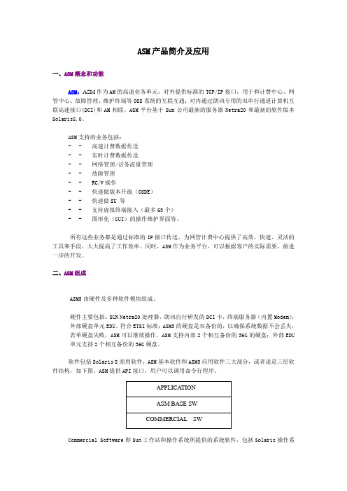
ASM 产品简介及应用一、 A SM 概念和功能ASM :ASM 作为AM 的高速业务单元,对外提供标准的TCP/IP 接口,用于和计费中心、网管中心、故障管理、维护终端等OSS 系统的互联互通;对内通过朗讯专用的双串行通道计算机互联高速接口(DCI)和AM 相联。
ASM 平台基于Sun 公司最新的服务器Netra20和最新的软件版本Solaris8.0。
ASM 支持的业务包括:-- 高速计费数据传送 -- 实时计费数据传送 -- 网络管理/话务流量管理 -- 故障管理 -- RC/V 操作 -- 快速做版本升级(OSDE ) -- 快速做SU 等 -- 支持虚拟终端接入(最多63个) -- 图形化(GUI )的操作维护界面等。
所有这些业务都是通过标准的IP 接口传送,为网管计费中心提供了高效、快速、灵活的工具和手段,大大提高了工作效率。
同时,ASM 作为业务平台,可以根据客户的实际需要,做进一步的开发。
二、ASM 组成ASM3由硬件及多种软件模块组成。
硬件主要包括:SUN Netra20处理器,朗讯自行研发的DCI 卡,终端服务器(内置Modem ),外部硬盘单元EDU 。
符合ETSI 标准;ASM3的硬盘是双备份的,以确保系统数据不会丢失,若单硬盘失败,ASM 可以继续操作。
ASM 支持内部2个相互备份的36G 的硬盘;外部EDU 单元支持2个相互备份的36G 硬盘。
软件包括Solaris 8商用软件,ASM 基本软件和ASM3应用软件三大部分,或者说是三层软件结构,如下图。
ASM 提供API 接口,用户可以调用命令行程序。
Commercial Software 即Sun 工作站和操作系统所提供的系统软件,包括Solaris操作系统、Netscape 、COBA 以及各种协议软件;ASM Base Software 包括VTTY 、EAI 应用、ASM API 等等;Application 包括图形界面、Proxy ODD 、软件的升级应用等等。
AMKASYN AC Servo和主轴电机:一般技术数据说明书

AMKASYNAC Servo and Main Spindle MotorsGeneral technical dataVersion: Part-No.: 2002/22 27853About this documentationName: PDK_027853_Motoren_Uebersicht_enWhat has changed:Copyright notice: © AMK GmbH & Co. KGCopying, communicating, and using the contents of this documentation is not permitted,unless otherwise expressed. Offenders are liable to the payment of damages. All rights arereserved in the event of the grant of a patent or the registration of a utility model or design.Reservation: We reserve the right to modify the content of the documentation as well as to the deliveryoptions for the product.Publisher: AMK Arnold Müller Antriebs- und Steuerungstechnik GmbH & Co. KGGaußstraße 37 – 39,73230 Kirchheim/TeckTel.: 07021/5005-0,Fax: 07021/5005-176E-Mail:********************Dr.h.c. Arnold Müller, Eberhard A.Müller, Dr. Günther VogtRegistergericht Stuttgart HRB 231283; HRA 230681Service: Phone: +49/(0)7021 / 5005-191, Fax -193Office hours: Mo-Fr 7.30 - 16.30, on weekends and holidays, the telephone number of theon-call service is provided through an answering machine. .You can assist us in finding a fast and reliable solution for the malfunction by providing ourservice personnel with the followingInformation located on the ID plate of the devicesthe software versionthe device setup and applicationthe type of malfunction, suspected cause of failurethe diagnostic messages (error messages)Internet address: www.amk-antriebe.deContent1 AMKASYN Motor Series DS, DV, DH and DW 41.1 Short description 42 General technical data 53 Technical Data Holding brake and External fan 63.1 Holding brake 63.2 External fan 64 Motor connection 74.1 Terminal box types and terminal block wiring 74.2 Connector types 84.3 Dimensions of the motor connector and connection wiring 85 Motor encoders 106 Abbreviations 127 Important notes 138 AMK Motor type codes 141 AMKASYN Motor Series DS, DV, DH and DW1.1 Short descriptionThe AMKASYN series of motors consits of the compact, highly dynamic AC-servo motor types DS and DV as well as the heavy-duty AC main spindle motor types DH and DW with high power density and precision balanced rotors.The AMKASYN motors are optimally tuned to be used with the AMKASYN digital AC-servo inverters for multi-motor applications in the power range of 1.3 to 75 kVA and with the AMKASYN digital compact servo drive in the power range of 0.7 to 50 kVA. Together the motors and inverters form an intelligent, digital drive system for servo and main spindle applications, which satisfies every demand.Advantages of the AMKASYN motor series Maintenance-freeSturdyPowerfulCompactHigh efficiencyOptimum power to weight ratiohighly dynamic responseHigh overload capacityWinding temperature sensors asprotection against overloadIntegrated encoder for speed andposition controlAreas of applicationThe AMKASYN motors are especially suitable for use as servo and main drive motors in: Plant construtionElevator technologyPrinting machinesWoodworking machinesPlastic processing machinesWarehousing and conveyortechnologyTest standsProcess engineeringTextile machinesPackaging machinesMachine tools2 General technical dataAmbient temperature: +5 ... +40°C / 94°F. At higher ambient temperatures up to maximum 60°C / 140°F the ratingdata must be reduced by 1% per 1° Kelvin temperature rise.Installation altitude: Up to 1000m / 3281ft above sea level. In operation above 1000m / 3281ft altitude, ambienttemperatures corresponding to DIN VDE 0530 table 4 shall be used as basis.Humidity: Maximum 85% relative humidity, non-condensating.Degree of protection: IP 54. Higher degree of protection on request.The stated maximum speeds apply for the IP 54 version with seal ring.Rating data: Refer to 100 Kelvin temperature rise in the windings. The test motor is mounted using athermally insulating flange.Insulating material class: F according to DIN VDE 0530.Thermal protection: PTC resistor, cold resistance approx. 150-800 Ω.Bearings: Ball bearings, lifetime lubricated.Axial eccentricity run-out: N according to DIN 42955.Balancing grade: G 2,5 corresponding to VDI 2056.Vibrational grade: N according to DIN ISO 2373.Painting: RAL 9005, flatt black.Cooling: Non-ventilated or fan-cooled; airflow toward output shaft. Reverse airflow as option.3 Technical Data Holding brake and External fan 3.1 Holding brakeThe motors can be equipped optionally with holding brakes. These are not suitable as service brakes. The brakes are lifted with 24V DC input. In the case of changed operating conditions, the operating instructions of the brake manufacturer must beobserved.For the maximum speed of the motor the maximum speed of the brake must also be considered.3.2 External fan4 Motor connectionDV, DH and DW motors feature terminal box connections for motor leads, fan and holding brake. The motors of the DS series and optionally of the DV series feature plug-style connectors. Connection cables with the corresponding cross-sections can be purchased preassembled.Shielded cables must be used for EMC reasons.* The current values IL for the connection cable refer to applications according to EN 60204-1:1992 in the cable laying type B2, or according to DIN 46200 for connection bolts.KG 1and KG 3 KG 4 and KG 5Picture name: ZCH_Motoren_Klemmkasten4.2 Connector types* The current values IL for the connection cable refer to applications according to EN 60204-1: 1992 in the cable laying type B24.3 Dimensions of the motor connector and connection wiringConnector pin designation is true for view on to the motor connector socket in each case. Power connection size BG 1picture name: ZCH_Motoren_Leistungsstecker1.0picture name: ZCH_Motoren_Leistungsstecker1.0_querPower connection size BG 1,5picture name: ZCH_Motoren_Leistungsstecker1,5picture name: ZCH_Motoren_Leistungsstecker1.5_querSocket and connector for external fanpicture name: ZCH_Motoren_Einbaudosepicture name: ZCH_Motoren_Anschlussstecker5 Motor encodersThe motors are equipped with one of these encoders.The motor maximum speed can be limited additionally by the encoder !picture name: ZCH_Motoren_Einbausteckdose_MotorgeberSignal description6 AbbreviationsMotor tables Holding brakeCharacter Unit Description Character Unit DescriptionM0Nm Zero speed torque M Br Nm Holding torqueM N Nm Rated torque n maxBR1/min Brake maximum speed P N kW Rated power U Br V Rated voltage 24V ≅n N 1/min rated speed (unregulated)n F1/min speed limit for constant rated power I BrJ Br Akgm2Brake rated currentBrake moment of interian max 1/min Maximum speed m Br kg Weight of the brake, total U N V Rated voltage motor weight is m + M BR I N A Rated currentJ kgm2 Rotor inertiam kg Motor weightkT Nm/A torque constant(M=I*kT) External fanQ I/min Rated flow rate Character Unit DescriptionΔT K Temperature rise of the liquid atpoint of rated operation U FI FVAExternal fan rated voltageExternal fan rated currentL Br mm Length of motor including brakeL1 Br mm Length of fan cooled motor includingbrake7 Important notesMotors can reach surface temperatures above 100°C / 212°F during operation. Before touching the motor check the surface temperature to avoid injury.In the case of motors with keyways and freely rotating shaft ends, the key must be removed or secured against being thrown off.Before opening the terminal box or pulling out or plugging in a connector on the motors, ensure that there is no voltage at the termination end. Voltage can be present a the connections even when the motor is not moving. If not complied with injuries or death may occur.A low-resistance connection of the motor housing to the PE ground bus in the control cabinet is required for trouble freeand safe operation of the motors.Pounding or uncontrolled impact of force onto the motor shaft during transport, storage and installation of the motors in the machine can lead to damage of the bearings and shaft.Inadmissible axial and radial loads lead to reduction of the bearing life. Bearing load diagrams are available on request.When using couplings, attention to correct assembly of the coupling components has to be observed. Alignment errors or offset of the coupling can lead to premature destruction of bearings and of the coupling.All motors listed may not be connected directly to the main power lines. The motors are intended exclusively foroperation on AMK inverter systems.8 AMK Motor type codespicture name: ZCH_Motoren_Typenschluessel_DVAMK Arnold Müller GmbH & Co. KG Antriebs- und Steuerungstechnik Gaußstrasse 37-3973230 Kirchheim/Teck DEUTSCHLANDTelefon: +49 (0) 70 21 / 50 05-0 Telefax: +49 (0) 70 21 / 50 05-199 ********************www.amk-antriebe.de。
三星 Sirius 3RN2温氨电机保护继电器说明书
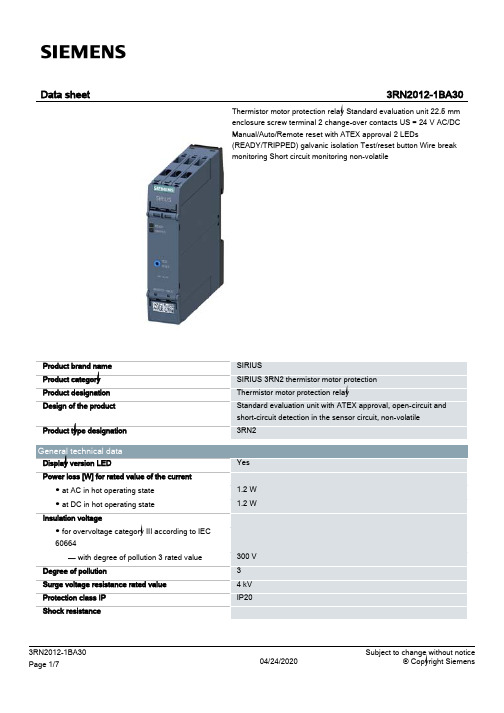
20 ... 12 20 ... 12
0.6 ... 0.8 N·m
Installation/ mounting/ dimensions Mounting position Mounting type Height Width Depth Required spacing ● with side-by-side mounting — forwards — Backwards — upwards — downwards — at the side ● for grounded parts — forwards — Backwards — upwards
Control circuit/ Control Type of voltage of the control supply voltage Control supply voltage at AC ● at 50 Hz rated value ● at 60 Hz rated value Control supply voltage at DC ● rated value Operating range factor control supply voltage rated value at DC ● initial value ● Full-scale value Operating range factor control supply voltage rated value at AC at 50 Hz ● initial value ● Full-scale value Operating range factor control supply voltage rated value at AC at 60 Hz ● initial value ● Full-scale value Inrush current peak ● at 24 V Duration of inrush current peak ● at 24 V
纳美电机产品简介说明书
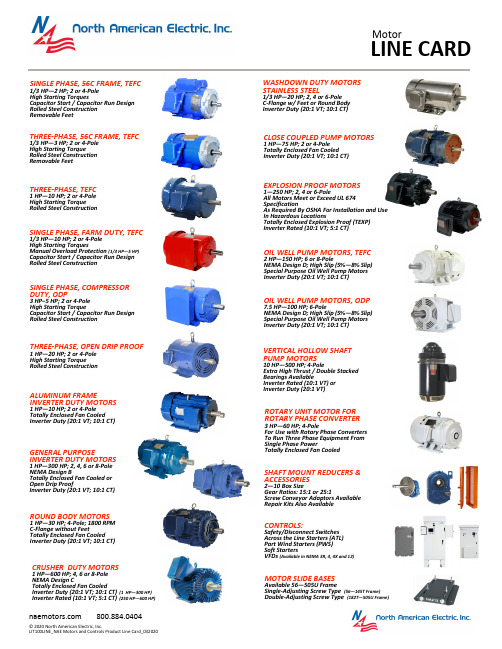
SINGLE PHASE, 56C FRAME, TEFC1/3 HP—2 HP; 2 or 4-Pole High Starting TorquesCapacitor Start / Capacitor Run Design Rolled Steel Construction Removable FeetSINGLE PHASE, COMPRESSOR DUTY, ODP3 HP–5 HP; 2 or 4-Pole High Starting TorqueCapacitor Start / Capacitor Run Design Rolled Steel ConstructionTHREE -PHASE, 56C FRAME, TEFC1/3 HP—3 HP; 2 or 4-Pole High Starting Torque Rolled Steel Construction Removable FeetTHREE -PHASE, TEFC1 HP—10 HP;2 or 4-Pole High Starting Torque Rolled Steel ConstructionTHREE -PHASE, OPEN DRIP PROOF1 HP—20 HP;2 or 4-Pole High Starting Torque Rolled Steel ConstructionWASHDOWN DUTY MOTORS STAINLESS STEEL1/3 HP—20 HP; 2, 4 or 6-Pole C -Flange w/ Feet or Round Body Inverter Duty (20:1 VT; 10:1 CT)CLOSE COUPLED PUMP MOTORS1 HP—75 HP;2 or 4-Pole Totally Enclosed Fan Cooled Inverter Duty (20:1 VT; 10:1 CT)EXPLOSION PROOF MOTORS1—250 HP; 2, 4 or 6-PoleAll Motors Meet or Exceed UL 674 SpecificationAs Required By OSHA For Installation and Use In Hazardous LocationsTotally Enclosed Explosion Proof (TEXP) Inverter Rated (10:1 VT; 5:1 CT)OIL WELL PUMP MOTORS, TEFC2 HP—150 HP; 6 or 8-PoleNEMA Design D; High Slip (5%—8% Slip) Special Purpose Oil Well Pump Motors Inverter Duty (20:1 VT; 10:1 CT)OIL WELL PUMP MOTORS, ODP7.5 HP—100 HP; 6-PoleNEMA Design D; High Slip (5%—8% Slip) Special Purpose Oil Well Pump Motors Inverter Duty (20:1 VT; 10:1 CT)VERTICAL HOLLOW SHAFT PUMP MOTORS10 HP—500 HP; 4-PoleExtra High Thrust / Double Stacked Bearings AvailableInverter Rated (10:1 VT) or Inverter Duty (20:1 VT)ROTARY UNIT MOTOR FOR ROTARY PHASE CONVERTER3 HP—60 HP; 4-PoleFor Use with Rotary Phase Converters To Run Three Phase Equipment From Single Phase PowerTotally Enclosed Fan CooledSHAFT MOUNT REDUCERS & ACCESSORIES2—10 Box SizeGear Ratios: 15:1 or 25:1Screw Conveyor Adaptors Available Repair Kits Also AvailableCONTROLS:Safety/Disconnect Switches Across the Line Starters (ATL) Part Wind Starters (PWS) Soft StartersVFDs (Available in NEMA 3R, 4, 4X and 12)MOTOR SLIDE BASESAvailable 56—505U FrameSingle -Adjusting Screw Type (56—145T Frame) Double -Adjusting Screw Type (182T—505U Frame)GENERAL PURPOSEINVERTER DUTY MOTORS1 HP—300 HP; 2, 4, 6 or 8-Pole NEMA Design BTotally Enclosed Fan Cooled or Open Drip ProofInverter Duty (20:1 VT; 10:1 CT)ALUMINUM FRAMEINVERTER DUTY MOTORS1 HP—10 HP;2 or 4-Pole Totally Enclosed Fan Cooled Inverter Duty (20:1 VT; 10:1 CT)SINGLE PHASE, FARM DUTY, TEFC1/3 HP—10 HP; 2 or 4-Pole High Starting TorquesManual Overload Protection (1/3 HP—5 HP) Capacitor Start / Capacitor Run Design Rolled Steel ConstructionCRUSHER DUTY MOTORS1 HP—600 HP; 4, 6 or 8-Pole NEMA Design CTotally Enclosed Fan CooledInverter Duty (20:1 VT; 10:1 CT) (1 HP—300 HP) Inverter Rated (10:1 VT; 5:1 CT) (250 HP—600 HP)ROUND BODY MOTORS1 HP—30 HP; 4-Pole; 1800 RPM C -Flange without FeetTotally Enclosed Fan Cooled Inverter Duty (20:1 VT; 10:1 CT)SAFETY SWITCHES – HEAVY DUTY30 AMP—1200 AMP 480 VAC / 600 VAC3-Pole / 3-Wire / Non -Fused or Fused NEMA 3R EnclosureVFD–ECONOMY1 HP—800 HP Variable Torque ½ HP—600 HP Constant Torque Siemens Series DriveNon -Combo, Circuit Breaker or Fused NEMA 3R, 4, 4X or 12 EnclosureSOFT STARTERS–CRUSHER/ULTRA20 HP—800 HPSAF MS6 Series DevicesUltra Heavy Duty (500% FLA for 30 Seconds) Full Start -Rated ContactorCircuit Breaker w/ Through Door NEMA 3R or 4/12 EnclosureSOFT STARTERS15 HP—300 HPSiemens 3RW40 Series Device Normal Duty or Heavy Duty Non -Combo or Circuit Breaker NEMA 3R, 4X or 4/12 EnclosurePART WIND STARTERS10 HP—200 HPIEC Rated Contactors Circuit Breaker or Fused NEMA 3R EnclosureACROSS THE LINE START-ERSNEMA 1—NEMA 5NEMA Full Rated ContactorCircuit Breaker or Fused w/ FlangedVFD–STANDARD1 HP—800 HP Variable Torque ½ HP—600 HP Constant Torque Siemens Series Drive Circuit Breaker or FusedNEMA 3R, 4, 4X or 12 EnclosureVFD–POSITIVE DISPLACEMENT PUMP3 HP—600 HPSiemens Series Drive Constant TorqueCircuit Breaker w/ Flanged NEMA 3R EnclosureVFD–IRRIGATION1 HP—800 HPSiemens Series Drive24/7 Programmable & 0—10 Backspin Timer Variable TorqueCircuit Breaker or Fused NEMA 3R EnclosureVFD–SUBMERSIBLE½ HP—200 HPSiemens Series Drive24/7 Programmable & 0—10 Backspin Timer Variable TorqueCircuit Breaker or Fused NEMA 3R EnclosureVFD–WASHDOWN/STAINLESS1 HP—200 HP Variable Torque ½ HP—150 HP Constant Torque Siemens Series Drive Circuit Breaker or Fused NEMA 4X EnclosureVFD–BEAM PUMP1 HP—200 HPSiemens Series Drive ReGen Avoidance Design Constant TorqueCircuit Breaker w/ Flanged NEMA 3R EnclosureCUSTOM PANELSMotor Controls Panel Customization Made EasyNAE Motor Controls offers customers the ability to custom configure and order their control panel to meet their specific needs and have it shipped quickly. All NAE packaged panels are backed by our 2 year warranty and eligible for up to 6 years of protection with the “NO Hassle ” Chassis Exchange program.NO Hassel Bumper to Bumper Chassis Exchange ProgramOptional three (3) year Warranty with Lightning & Surge Protection including NAE ’s “No Hassel ” Chassis Exchange program.Scan or visit our website at to learn more.。
MOXA V3200 Series 11th Gen Intel Core 铁路计算机说明书

V3200Series11th Gen Intel®Core™processor railway computers with power isolation,multiple expansion slots for wireless,2SSD slotsFeatures and Benefits•Intel®Celeron®/Intel®Core™i3/i5/i7embedded computer for in-vehicleapplications•Multiple interfaces:Up to8GbE,2serial,2USB ports,2DIs,2DOs,and2M.2B key slots for wireless(5G),1mPCIe slot for wireless(Wi-Fi5or4G),1M.2E key for wireless(Wi-Fi6)•Supports dual independent displays(VGA and HDMI with4K resolution)•Native TSN support(for models with i7-1185GRE processor)•Onboard TPM module for enhanced cybersecurity•Complies with all EN50155mandatory test items1•Compliant with EN50121-4•IEC61373certified for shock and vibration resistanceCertificationsIntroductionThe V3200Series embedded computers are built around an Intel®Core™i7/i5/i3or Intel®Celeron®high-performance processor and come with up to64GB RAM,one M.22280M key slot,and two2.5"SSD slots for storage expansion.The computers are compliant with EN50155:2017and EN50121-4standards covering operating temperature,power input voltage,surge,ESD,and vibration,making them suitable for railway onboard and wayside applications.For connecting with onboard and wayside systems and devices,the V3200computers are equipped with a rich set of interfaces including4Gigabit Ethernet ports(default;can go up to8ports)with one-pair LAN bypass function to ensure uninterrupted data transmission,2RS-232/422/485serial ports,2DIs,2DOs,and2USB3.0ports.The built-in TPM2.0module ensures platform integrity and provides hardware-based security as well as protection from tampering.Vehicular applications require reliable connectivity.They also require clear indicators on the device that identify the status of the software.TheV3200computers come with two5G/one LTE and6SIM-card slots to help establish redundant LTE/Wi-Fi connections and three programmable LEDs that enable monitoring of the runtime status of software.1.This product is suitable for rolling stock railway applications,as defined by the EN50155standard.For a more detailed statement,click here:/doc/specs/EN_50155_Compliance.pdfAppearance Front View8P ModelsFront View4P ModelsRear ViewSpecificationsComputerCPU V3210-TL1-4L-T/8L-T/4L-CT-T/8L-CT-T:Intel®Celeron®6305E processor(2C/2T,4M cache,1.8GHz)V3210-TL3-4L-T/8L-T/4L-CT-T/8L-CT-T:Intel®Core™i3-1115G4E processor(2C/4T,6M cache,2.2GHz)V3210-TL5-4L-T/8L-T/4L-CT-T/8L-CT-T:Intel®Core™i5-1145G7E processor(4C/8T,8M cache,1.5GHz)V3210-TL7-4L-T/8L-T/4L-CT-T/8L-CT-T:Intel®Core™i7-1185G7E processor(4C/8T,12M cache,1.8GHz)V3210-TL7-4L-TSN-CT-T/8L-TSN-CT-T:Intel®Core™i7-1185GRE processor(4C/8T,12M cache,1.8GHz) System Memory Slot SODIMM DDR4slots x2(64GB max)System Memory Pre-installed16GB DDR4Storage Slot 2.5-inch SSD slots x2M.2M key2280slot x1(NVMe;128GB preinstalled)Supported OS Windows10Embedded IoT Ent2021LTSC64-bitLinux Debian11/Ubuntu20.04/CentOS7.9(driver)Graphics Controller Intel®Celeron®/Core™i3Models:Intel®UHD GraphicsIntel®Core™i5/i7Models:Intel®Iris®Xe GraphicsComputer InterfaceEthernet Ports Default:4ports(2.5GbE x1and GbE x3),can go up to8portsAuto-sensing1000/2500Mbps x1Auto-sensing10/100/1000Mbps x up to7LAN1:Intel®Ethernet Network Adapter I225with Intel®AMT support Serial Ports RS-232/422/485ports x2,software selectable(DB9male)Digital Input DIs x2Digital Output DOs x2USB3.0USB3.0hosts x2,type-A connectorsVideo Output VGA x1,15-pin D-sub connector(female)HDMI x1,HDMI connector(type A)Wi-Fi Antenna Connector QMA x8(optional with accessory kit)Expansion Slots M.2B key3052/3050slots x2(for5G;4Micro SIMs)M.2E key slots x1(for Wi-Fi6)mPCIe slots x1(for cellular with2Micro SIMs,Wi-Fi5,or I/O expansion) SIM Format MicroNumber of SIMs6TPM TPM v2.0Digital InputsConnector Screw-fastened Euroblock terminalIsolation3k VDCSensor Type Dry contactWet contact(NPN)Dry Contact Logic0:Close to GNDLogic1:OpenWet Contact(COM to DI)Logic0:10to30VDCLogic1:0to3VDCDigital OutputsConnector Screw-fastened Euroblock terminalCurrent Rating200mA per channelI/O Type SinkVoltage0to30VDCIsolation3k VDCLED IndicatorsSystem Power x1Storage x1LAN2per port(LAN1:1000/2500Mbps,LAN2to LAN8:100/1000Mbps)1per LAN bypass pair(LAN7-LAN8)Serial2per port(Tx,Rx)User Programmable3Serial InterfaceBaudrate50bps to115.2kbpsConnector DB9maleESD Contact:6kV;Air:8kV(level3)Isolation2kVData Bits5,6,7,8Stop Bits1,1.5,2Parity None,Even,Odd,Space,MarkFlow Control RTS/CTS,XON/XOFFAutomatic Data Direction Control(ADDC)for RS-485RTS Toggle(RS-232only)Serial SignalsRS-232TxD,RxD,RTS,CTS,DTR,DSR,DCD,GNDRS-422Tx+,Tx-,Rx+,Rx-,GNDRS-485-2w Data+,Data-,GNDRS-485-4w Tx+,Tx-,Rx+,Rx-,GNDPower ParametersInput Voltage24to110VDCPower Connector M12A-coded male connectorPower Consumption100W(max.)Physical CharacteristicsHousing AluminumDimensions(without ears)249x88.9x180mm(9.80x3.50x7.09in) Weight Product Only:3.86kg(8.51lb)Product With Package:5.10kg(11.24lb)IP Rating IP30Installation Wall mountingProtection PCB conformal coatingAvailable on requestEnvironmental LimitsOperating Temperature-40to70°C(-40to158°F)Storage Temperature(package included)-40to85°C(-40to185°F)Ambient Relative Humidity5to95%(non-condensing)Standards and CertificationsEMC EN55032/35EMI CISPR32,FCC Part15B Class AEMS IEC61000-4-2ESD:Contact:6kV;Air:8kVIEC61000-4-3RS:80MHz to1GHz:20V/mIEC61000-4-4EFT:Power:2kV;Signal:2kVIEC61000-4-5Surge:Power:2kVIEC61000-4-6CS:10VIEC61000-4-8PFMFSafety EN62368-1IEC62368-1UL62368-1Railway Fire Protection EN45545-2:2020Railway EN50121-4EN50121-3-2EN50155:2017Shock IEC60068-2-27,IEC61373Vibration IEC60068-2-64,IEC61373DeclarationGreen Product RoHS,CRoHS,WEEEMTBFTime4L Models:382,624hrs8L Models:305,836hrsStandards Telcordia(Bellcore),GBWarrantyWarranty Period3yearsDetails See /warrantyPackage ContentsDevice1x V3200Series computer Installation Kit4x SSD/HDD brackets1x wall-mounting kit Documentation1x quick installation guide1x warranty card Dimensions8P Models4P ModelsOrdering InformationModel NameCPUMemoryOS Storage (M.2M Key) 2.5"SSD Slots (2)GbE PortsTPM 2.0Native TSN Enhance mentPower InputOperating Temp.Conforma l CoatingV3210-TL1-4L-TCeleron 6305E 16GB 128GBOptional 4✓–24-110VDC -40to 70°C –V3210-TL3-4L-T i3-1115G4E16GB 128GB Optional 4✓–24-110VDC -40to 70°C –V3210-TL3-4L-CT-T i3-1115G4E 16GB 128GB Optional 4✓–24-110VDC -40to 70°C ✓V3210-TL7-4L-T i7-1185G7E 16GB 128GB Optional 4✓–24-110VDC -40to 70°C –V3210-TL1-8L-CT-T Celeron 6305E 16GB 128GB Optional 8✓–24-110VDC -40to 70°C ✓V3210-TL5-8L-CT-T i5-1145G7E16GB 128GB Optional 8✓–24-110VDC-40to 85°C✓2.0V3210-TL7-8L-CT-T i7-1185G7E16GB128GB Optional8✓–24-110VDC-40to70°C✓V3210-TL7-8L-TSN-CT-T i7-1185GRE16GB128GB Optional8✓✓24-110VDC-40to70°C✓Accessories(sold separately)CablesCBL-M12(FF5P)/OPEN-100IP67A-coded M12-to-5-pin power cable,IP67-rated5-pin female M12connector,1m©Moxa Inc.All rights reserved.Updated Sep21,2023.This document and any portion thereof may not be reproduced or used in any manner whatsoever without the express written permission of Moxa Inc.Product specifications subject to change without notice.Visit our website for the most up-to-date product information.。
CLA80MT1200NHB三相三簇电流三极管数据手册说明书
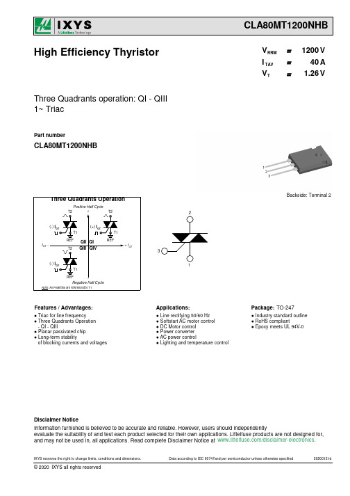
Package: TO-247
● Industry standard outline ● RoHS compliant ● Epoxy meets UL 94V-0
Disclaimer Notice
Information furnished is believed to be accurate and reliable. However, users should independently evaluate the suitability of and test each product selected for their own applications. Littelfuse products are not designed for, and may not be used in, all applications. Read complete Disclaimer Notice at /disclaimer-electronics.
MD
mounting torque
F C
mounting force with clip
Product Marking
Logo Part Number
Date Code
Lot# Location
IXYS
XXXXXXXXX yywwZ 1234
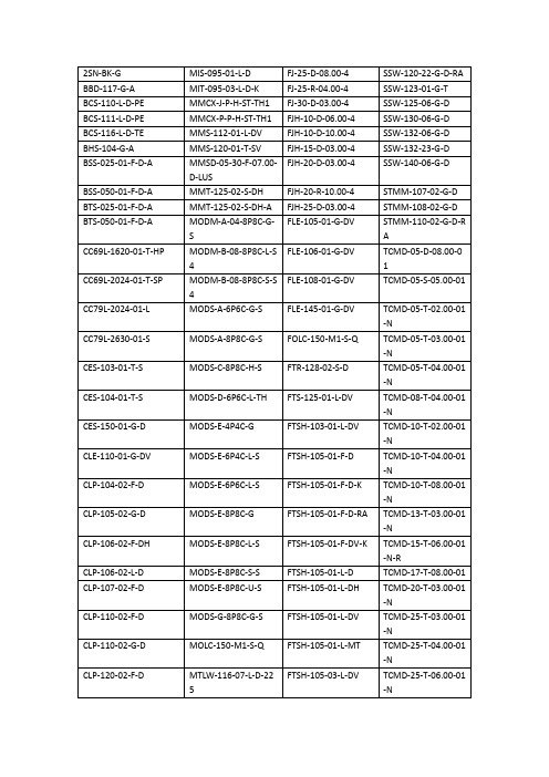
samtec型号
FJH-15-D-03.00-4
SSW-132-23-G-D
BSS-025-01-F-D-A
MMSD-05-30-F-07.00-D-LUS
FJH-20-D-03.00-4
SSW-140-06-G-D
BSS-050-01-F-D-A
MMT-125-02-S-DH
FJH-20-R-10.00-4
FTSH-140-02-F-D
TMM-114-01-L-D-RA
EHF-113-01-L-D-SM
SFM-125-02-S-D-A
FW-06-04-F-D-425-075
TMM-120-03-G-S
EHF-113-01-L-D-SM-LC
SFM-125-02-S-S-LC
FW-12-03-G-D-250-150
MODM-B-08-8P8C-L-S4
FLE-106-01-G-DV
TCMD-05-D-08.00-01
CC69L-2024-01-T-SP
MODM-B-08-8P8C-S-S4
FLE-108-01-G-DV
TCMD-05-S-05.00-01
CC79L-2024-01-L
MODS-A-6P6C-G-S
TFM-105-31-S-D
DWM-24-54-G-S-319
QTH-030-05-F-D-A
FTSH-117-01-L-DV
TFM-107-01-S-D-RA
DWM-25-54-G-S-319
QTH-030-08-F-D-A
FTSH-120-01-F-D
TFM-110-01-S-D
DWM-25-61-G-S-810
TFM-115-01-S-D
HSMJ-A101-S00J1中文资料

DescriptionThis family of SMT LEDs is packaged in the industry standard PLCC-2 package. These SMT LEDs have high reliability performance and are designed to work under a wide range of environmental conditions. This high reliability feature makes them ideally suited to be used under harsh interior automotive as well as interior signs application conditions.To facilitate easy pick & place assembly, the LEDs are packed in EIA-compliant tape and reel. Every reel will be shipped in single intensity and color bin, except red color, to provide close uniformity.These LEDs are compatible with IR solder reflow process. Due to the high reliability feature of these products, they can also be mounted using through-the-wave soldering process.The super wide viewing angle at 120˚ makes these LEDs ideally suited for panel, push button, or general backlighting in automotive interior, office equipment, industrial equipment, and home appliances. The flat top emitting surface makes it easy for these LEDs to mate with light pipes. With the built-in reflector pushing up the intensity of the light output, these LEDs are also suitable to be used as LED pixels in interior elec-tronic signs.Features• Industry standard PLCC-2 package • High reliability LED package• High brightness using AlInGaP and InGaN dice tech-nologies • Available in full selection of colors • Super wide viewing angle at 120˚• Available in 8 mm carrier tape on 7 inch reel (2000 pieces)• Compatible with both IR and TTW soldering processApplications• Interior automotive– Instrument panel backlighting – Central console backlighting – Cabin backlighting • Electronic signs and signals – Interior full color sign – Variable message sign• Office automation, home appliances, industrial equipment– Front panel backlighting – Push button backlighting – Display backlightingHSMx-A10x-xxxxx PLCC-2Surface Mount LED IndicatorData SheetCAUTION: HSMN,M,K and E-A10x-xxxxx LEDs are Class 2 ESD sensitive. Please observe appropriate precau-tions during handling and processing. Refer to Avago Application Note AN-1142 for additional details.Package Dimensions(ANODE MARKING FOR AlGaAs DEVICES)TOP MOUNTREVERSE MOUNTNOTE: ALL DIMENSIONS IN MILLIMETERS.Device Selection GuideRedPart Number Min. Iv (mcd) Typ. Iv (mcd) Max. Iv (mcd) Test Current (mA) Dice Technology HSMS-A100-J00J1 4.0 15.0 - 20 GaP HSMS-A100-L00J1 10.0 15.0 - 20 GaP HSMS-A100-H70J2 .0 - 8.0 10 GaP HSMS-A100-J80J2 5.0 - 15.5 10 GaP HSMH-A100-L00J1 10.0 15.0 - 20 AlGaAs HSMH-A100-N00J1 25.0 50.0 - 20 AlGaAs HSMH-A100-L70J2 12.5 - 2.0 10 AlGaAs HSMH-A100-M80J2 20.0 - 62.0 10 AlGaAs HSMH-A100-P 0J1 40.0 - 100.0 20 AlGaAs HSMC-A100-J00J1 4.0 100.0 - 20 AlInGaP HSMC-A100-Q00J1 6 .0 100.0 - 20 AlInGaP HSMC-A100-R00J1 100.0 140.0 - 20 AlInGaP HSMC-A101-S00J1 160.0 220.0 - 20 AlInGaP HSMZ-A100-T00J1 250.0 50.0 - 20 AlInGaP HSMC-A100-P 0J1 40.0 - 100.0 20 AlInGaP HSMC-A101-R80J1 125.0 - 95.0 20 AlInGaP HSMZ-A100-S80J1 200.0 - 620.0 20 AlInGaPRed OrangePart Number Min. Iv (mcd) Typ. Iv (mcd) Max. Iv (mcd) Test Current (mA) Dice Technology HSMJ-A100-Q00J1 6 .0 100.0 - 20 AlInGaP HSMJ-A101-S00J1 160.0 200.0 - 20 AlInGaP HSMV-A100-T00J1 250.0 50.0 - 20 AlInGaP HSMJ-A100-Q 0J1 6 .0 - 155.0 20 AlInGaP HSMJ-A100-R40J1 100.0 - 15.0 20 AlInGaP HSMJ-A101-R80J1 125.0 - 95.0 20 AlInGaP HSMV-A100-S80J1 200.0 - 620.0 20 AlInGaPOrangePart Number Min. Iv (mcd) Typ. Iv (mcd) Max. Iv (mcd) Test Current (mA) Dice Technology HSMD-A100-J00J1 4.0 15.0 - 20 GaP HSMD-A100-L00J1 10.0 15.0 - 20 GaP HSMD-A100-J7PJ2 5.0 - 12.5 10 GaP HSMD-A100-K4PJ2 6. - 20.0 10 GaPHSML-A100-Q00J1 6 .0 100.0 - 20 AlInGaP HSML-A101-S00J1 160.0 220.0 - 20 AlInGaP HSML-A100-Q7PJ1 80.0 - 200.0 20 AlInGaP HSML-A100-R7PJ1 125.0 - 15.0 20 AlInGaP HSML-A101-R8WJ1 125.0 - 95.0 20 AlInGaPDevice Selection Guide, continuedYellow/AmberPart Number Min. Iv (mcd) Typ. Iv (mcd) Max. Iv (mcd) Test Current (mA) Dice Technology HSMY-A100-J00J1 4.0 12.0 - 20 GaP HSMY-A100-L00J1 10.0 12.0 - 20 GaP HSMY-A100-J 5J2 4.0 - 10.0 10 GaP HSMY-A100-K45J2 6. - 20.0 10 GaP HSMA-A100-Q00J1 6 .0 100.0 - 20 AlInGaP HSMA-A101-S00J1 160.0 220.0 - 20 AlInGaP HSMU-A100-S00J1 160.0 20.0 - 20 AlInGaP HSMA-A100-Q 5J1 6 .0 - 155.0 20 AlInGaP HSMA-A100-R45J1 100.0 - 15.0 20 AlInGaP HSMA-A101-R8WJ1 125.0 - 95.0 20 AlInGaP HSMU-A100-S4WJ1 160.0 - 500.0 20 AlInGaPYellow GreenPart Number Min. Iv (mcd) Typ. Iv (mcd) Max. Iv (mcd) Test Current (mA) Dice Technology HSMG-A100-J02J1 4.0 18.0 - 20 GaP HSMG-A100-K72J2 8.0 - 20.0 10 GaP HSME-A100-M02J1 16.0 70.0 - 20 AlInGaP HSME-A100-N82J1 0.0 - 100.0 20 AlInGaPEmerald GreenPart Number Min. Iv (mcd) Typ. Iv (mcd) Max. Iv (mcd) Test Current (mA) Dice Technology HSMG-A100-H01J1 2.5 8.0 - 20 GaP HSMG-A100-G 1J2 1.6 - 4.0 10 GaP HSMG-A100-H41J2 2.5 - 8.0 10 GaP HSME-A100-L01J1 10.0 40.0 - 20 AlInGaP HSME-A100-M PJ1 16.0 - 40.0 20 AlInGaPGreenPart Number Min. Iv (mcd) Typ. Iv (mcd) Max. Iv (mcd) Test Current (mA) Dice Technology HSMM-A101-R00J1 100.0 200.0 - 20 InGaN HSMM-A100-S00J1 160.0 50.0 - 20 InGaN HSMM-A101-Q7PJ1 80.0 - 200.0 20 InGaN HSMM-A101-R7PJ1 125.0 - 15.0 20 InGaN HSMM-A101-R8PJ1 125.0 - 95.0 20 InGaN HSMM-A100-S8PJ1 200.0 - 620.0 20 InGaNDevice Selection Guide, continuedCyanPart Number Min. Iv (mcd) Typ. Iv (mcd) Max. Iv (mcd) Test Current (mA) Dice Technology HSMK-A101-R00J1 100.0 170.0 - 20 InGaNHSMK-A100-S00J1 160.0 280.0 - 20 InGaNHSMK-A100-S8WJ1 200.0 - 620.0 20 InGaNHSMK-A101-Q WJ1 6 .0 - 155.0 20 InGaNHSMK-A101-R4WJ1 100.0 - 15.0 20 InGaNBluePart Number Min. Iv (mcd) Typ. Iv (mcd) Max. Iv (mcd) Test Current (mA) Dice Technology HSMB-A100-J00J1 4.0 15.0 - 20 GaNHSMB-A100-J70J2 5.0 - 12.5 10 GaNHSMB-A100-K80J2 8.0 - 25.0 10 GaNHSMN-A101-N00J1 25.0 50.0 - 20 InGaNHSMN-A100-P00J1 40.0 70.0 - 20 InGaNHSMN-A101-N7YJ1 0.0 - 80.0 20 InGaNHSMN-A100-P8YJ1 50.0 - 155.0 20 InGaNNote:1. The luminous intensity, I v, is measured at the mechanical axis of the lamp package. The actual peak of the spatial radiation pattern may not be aligned with this axis.Part Numbering SystemHSM x1 - A x2 x x4 -x5x6 x7 x8x9Packaging OptionColor Bin SelectionIntensity Bin SelectDevice Specific ConfigurationPackage TypeLED Chip ColorAbsolute Maximum Ratings (T A = 25°C)Parameters HSMS/D/Y/G HSMH HSMC/J/L/A HSME HSMZ/V/U HSMM/K/B/N DC Forward Current[1] 0 mA 0 mA 0 mA[ ,4]20 mA[4] 0 mA[ ,4] 0 mA Peak Forward Current[2]100 mA 100 mA 100 mA 100 mA 100 mA 100 mA Power Dissipation 6 mW 60 mW 6 mW 48 mW 72 mW 114 mW Reverse Voltage 5 VJunction Temperature 110°COperating Temperature –55°C to +100°CStorage Temperature –55°C to +100°CNotes:1. Derate linearly as shown in Figure 4.2. Duty factor = 10%, Frequency = 1 kHz.. Drive current between 10 mA and 0 mA is recommended for best long term performance.4. Operation at current below 5 mA is not recommended.Electrical Characteristics (T A = 25˚C) Forward Voltage Reverse Voltage Reverse Voltage ThermalV F (Volts) @ I F = 20 mA V R @ 100 µA V R @ 10 µA Resistance Part Number Typ. Max. Min. Min. R θJP (°C/W)HSMS/D/Y/G 2.2 2.6 5 — 180HSMH 1.9 2.6 5 — 180HSMC/J/L/A/E 1.9 2.4 5 — 280HSMZ/V/U 2.2 2.6 5 — 280HSMB .9 4. — 5 280HSMM/K/N .44.05—5280Optical Characteristics (T A = 25˚C)ViewingLuminous PeakDominant Angle Luminous Intensity/ Wavelength Wavelength [1] 2 θ1/2[2] Efficacy ηv [3] Total FluxDiceλPEAK (nm) λD (nm) (Degrees) (lm/W) I v (mcd)/Φv (mlm) Color Part Number Technology Typ. Typ. Typ. Typ. Typ.Red HSMS-A100 GaP 6 5 626 120 120 0.45 HSMH-A100 AlGaAs 645 6 7 120 6 0.45 HSMC-A10x AlInGaP 6 5 626 120 150 0.45 HSMZ-A100 AlInGaP 6 9 6 0 120 155 0.45Red HSMJ-A10x AlInGaP 621 615 120 240 0.45OrangeHSMV-A100 AlInGaP 62 617 120 26 0.45Orange HSMD-A100 GaP 600 602 120 80 0.45 HSML-A10x AlInGaP 609 605 120 20 0.45Amber HSMY-A100 GaP 58 585 120 520 0.45 HSMA-A10x AlInGaP 592 590 120 480 0.45 HSMU-A100 AlInGaP 594 592 120 500 0.45Yellow HSMG-A100 GaP 565 569 120 590 0.45Green HSME-A100 AlInGaP 575 570 120 560 0.45Emerald HSMG-A100 GaP 558 560 120 650 0.45GreenHSME-A100 AlInGaP 566 560 120 610 0.45Green HSMM-A10x InGaN 52 525 120 500 0.45Cyan HSMK-A10x InGaN 502 505 120 00 0.45Blue HSMB-A100 GaN 428 462 120 65 0.45HSMN-A10xInGaN468470120750.45Notes:1. The dominant wavelength, λD , is derived from the CIE Chromaticity Diagram and represents the color of the device.2. θ1/2 is the off-axis angle where the luminous intensity is 1/2 the peak intensity.. Radiant intensity, I e in watts/steradian, may be calculated from the equation I e = I v /ηv , where I v is the luminous intensity in candelas and ηv is the luminous efficacy in lumens/watt.Figure 1. Relative intensity vs. wavelength.Figure 2. Forward current vs. forward voltage.Figure 3. Relative intensity vs. forward current.Figure 4. Maximum forward current vs. ambient temperature. Derated based on T J MAX = 110˚C, RθJA= 500˚C/W.Figure 5. Dominant wavelength vs. forwardcurrent – InGaN devices.FORWARD VOLTAGE – V103035 F O R W A R D C U R R E N T – m A5201525Figure 4b. Maximum Forward Current Vs. Solder Point Temperature. Derated based on T J MAX = 110°C, RθJP= 180°C/W or 280°C/W.101520253035TEMPERATURE (°C)C U R R E N T - mA5101520253035TEMPERATURE (°C)C U R R E N T - m ACURRENT – mA460480540 D O M I N A N T W A V E L E N G T H – n mHSMx-A100 fig 5500470510490520530Figure 8a. Recommended SnPb reflow soldering profile.Figure 7. Radiation Pattern.D E L T A V F (N O R M A L I Z E D A T 25°C )-0.3TEMPERATURE – °C0.50.40.20.10-0.2-0.10.3Figure 6. Forward voltage shift vs. temperature.Figure 8b. Recommended Pb-free reflow soldering profile.(Acc. to J-STD-020C)TIMET E M P E R A T U R ET E M P E R A T U R E – °CNote: For detail information on reflow soldering of Avago surfaceFigure 11. Tape leader and trailer dimensions.Figure 12. Tape dimensions.Figure 13. Reel dimensions.Figure 14. Reeling orientation.11Intensity Bin Select (X5X6) Individual reel will contain parts from one half bin only.X5Min I v BinX60 Full Distributionhalf bins starting from X514 4 half bins starting from X515 5 half bins starting from X517 half bins starting from X528 4 half bins starting from X529 5 half bins starting from X52 Intensity Bin LimitsBin ID Min. (mcd) Max. (mcd) G1 1.80 2.24G2 2.24 2.80H1 2.80 .55H2 .55 4.50J1 4.50 5.60J2 5.60 7.20K1 7.20 9.00K2 9.00 11.20L1 11.20 14.00L2 14.00 18.00M1 18.00 22.40M2 22.40 28.50N1 28.50 5.50N2 5.50 45.00P1 45.00 56.00P2 56.00 71.50Q1 71.50 90.00Q2 90.00 112.50 R1 112.50 140.00 R2 140.00 180.00 S1 180.00 224.00 S2 224.00 285.00 T1 285.00 55.00 T2 55.00 450.00 U1 450.00 560.00 U2 560.00 715.00 V1 715.00 900.00 V2 900.00 1125.00 Tolerance of each bin limit = ± 12%.Color Bin Select (X7)Individual reel will contain partsfrom one full bin only.X70 Full DistributionZ A and B onlyY B and C onlyW C and D onlyV D and E onlyU E and F onlyT F and G onlyS G and H onlyQ A, B, and C onlyP B, C, and D onlyN C, D, and E onlyM D, E, and F onlyL E, F, and G onlyK F, G, and H only1 A, B, C, and D only2 E, F, G, and H onlyB, C, D, and E only4 C, D, E, and F only5 A, B, C, D, and E only6 B, C, D, E, and F onlyColor Bin LimitsBlue Min. (nm) Max. (nm)A 460.0 465.0B 465.0 470.0C 470.0 475.0D 475.0 480.0Green Min. (nm) Max. (nm)A 515.0 520.0B 520.0 525.0C 525.0 5 0.0D 5 0.0 5 5.0Cyan Min. (nm) Max. (nm)A 490.0 495.0B 495.0 500.0C 500.0 505.0D 505.0 510.0Color Bin LimitsEmeraldGreen Min. (nm) Max. (nm)A 552.5 555.5B 555.5 558.5C 558.5 561.5D 561.5 564.5Orange Min. (nm) Max. (nm)A 597.0 600.0B 600.0 60 .0C 60 .0 606.0D 606.0 609.0E 609.0 612.0Red Orange Min. (nm) Max. (nm)A 611.0 616.0B 616.0 620.0Red Min. (nm) Max. (nm)Full DistributionTolerance of each bin limit = ± 1 nm.Amber Min. (nm) Max. (nm)A 582.0 584.5B 584.5 587.0C 587.0 589.5D 589.5 592.0E 592.0 594.5F 594.5 597.0YellowGreen Min. (nm) Max. (nm)E 564.5 567.5F 567.5 570.5G 570.5 57 .5H 57 .5 576.512Packaging Option (X 8X 9)Option Test Current Package Type Reel Size J1 20 mA Top Mount 7 inch J4 20 mA Top Mount 1 inch H1 20 mA Reverse Mount 7 inch H4 20 mA Reverse Mount 1 inch J2 10 mA Top Mount 7 inch J5 10 mA Top Mount 1 inch H2 10 mA Reverse Mount 7 inch H5 10 mA Reverse Mount1 inchFor product information and a complete list of distributors, please go to our website: Avago, Avago Technologies, and the A logo are trademarks of Avago Technologies Limited in the United States and other countries.Data subject to change. Copyright © 2007 Avago Technologies Limited. All rights reserved. Obsoletes AV01-0040EN AV02-0198EN - May 30, 2007Moisture SensitivityThis product is qualified as Moisture Sensitive Level 2a per Jedec J-STD-020. Precautions when handling this moisture sensitive product is important to ensure the reliability of the product. Do refer to Avago Application Note AN5 05 Handling of Moisture Sensitive Surface Mount Devices for details.A. Storage before use- Unopen moisture barrier bag (MBB) can be stored at <40°C/90%RH for 12 months. If the actual shelf life has exceeded 12 months and the HIC indicates that baking is not required, then it is safe to reflow the LEDs per the original MSL rating.- It is not recommended to open the MBB prior to assembly (e.g. for IQC).B. Control after opening the MBB- The humidity indicator card (HIC) shall be read im-mediately upon opening of MBB.- The LEDs must be kept at < 0°C / 60%RH at all time and all high temperature related process including soldering, curing or rework need to be completed within 672 hours.C. Control for unfinished reel- For any unuse LEDs, they need to be stored in sealed MBB with desiccant or desiccator at <5%RH.D. Control of assembled boards- If the PCB soldered with the LEDs is to be subjected to other high temperature processes, the PCB need to be stored in sealed MBB with desiccant or desic-cator at <5%RH to ensure no LEDs have exceeded their floor life of 672 hours.E. Baking is required if:- “10%” or “15%” HIC indicator turns pink.- The LEDs are exposed to condition of > 0°C / 60% RH at any time.- The LEDs floor life exceeded 672 hours.Recommended baking condition: 60±5°C for 20 hours.。
ASMT-YTB2-0BB02高亮度三色PLCC6黑顶面LED数据表说明书
ASMT-YTB2-0BB02High Brightness Tricolor PLCC6 Black Surface LEDData SheetDescriptionThe high brightness black top surface tri-color PLCC-6 family of SMT LEDs has a separate heat path for each LED dice, enabling the LE D to be driven at higher current. These SMT LE Ds are in the high brightness category, are high reliability devices, are high performance and are designed for a wide range of environmental condi-tions. By integrating the black top surface Avago devices deliver better contrast enhancement for your applica-tion. They also provide super wide viewing angle at 120° with the built in reflector pushing up the intensity of the light output. The high reliability characteristics and other features make the black top surface tri-color PLCC-6 family ideally suitable for exterior and interior full color signs ap-plication conditions.For easy pick & place, the LEDs are shipped in EIA-com-pliant tape and reel. E very reel is shipped from a singleintensity and color bin; except red color providing betteruniformity. These tri-color LE Ds are compatible with reflow soldering process.Features• Industry Standard PLCC-6 package (Plastic Leaded Chip Carrier) with individual addressable pin-out for higher flexibility of driving configuration • High reliability LED package with silicone encapsulation • High brightness using AlInGaP and InGaN dice technologies • Wide viewing angle at 120°• Compatible with reflow soldering process • JEDEC MSL 2a• Water-Resistance (IPX6*) per IEC 60529:2001* The test is conducted on component level by mounting the components on PCB with proper potting to protect the leads. It is strongly recommended that customers perform necessary tests on the components for their final application.Applications • Indoor and outdoor full color display CAUTION: LEDs are Class 1C ESD sensitive. Please observe appropriate precautions during han-dling and processing. Please refer to Avago Application Note AN-1142 for additional details.Table 1. Device Selection GuidePart NumberColor 1 - AlInGaP Red Color 2 - InGaN Green Color 3 - InGaN Blue Min. Iv @20mATyp. Iv @ 20mA Max Iv @ 20mA Min. Iv @ 20mA Typ. Iv @ 20mA Max Iv @ 20mA Min. Iv @ 20mA Typ. Iv @ 20mA Max Iv @ 20mA Bin ID (mcd)(mcd)(mcd)Bin ID (mcd)(mcd)(mcd)Bin ID (mcd)(mcd)(mcd)ASMT-YTB2-0BB02U25607451125W1112516002240T1285380560Notes:1. The luminous intensity I V , is measured at the mechanical axis of the LED package and it is tested in pulsing condition. The actual peak of the spatialradiation pattern may not be aligned with this axis.2. Tolerance = ± 12%Part Numbering SystemPackaging Option Color Bin Selection Intensity Bin Limit Intensity Bin SelectionDevice Speci cation Con guration Package Type B: Black Surface Tricolor ColorT: TricolorProduce FamilyY: Silicone Based PLCC6Notes:1. All Dimensions are in millimeters2. Tolerance = ±0.2 mm unless otherwise specified3. Terminal Finish: Ag plating4. Encapsulantion material: silicone resinLead Configuration1Cathode Blue 2Cathode Green 3Cathode Red 4Anode Red 5Anode Green 6AnodeBluePackage DimensionsTable 2. Absolute Maximum Ratings (T A = 25°C)Parameter Red Green & Blue Unit DC forward current [1] 5030mA Peak forward current [2]100100mA Power dissipation125114mW Reverse voltage4V[3]V Maximum junction temperature T j max125°C Operating temperature range -40 to + 110[4]°C Storage temperature range-40 to + 120°C Notes:1. Derate linearly as shown in Figure 4a & 4b.2. Duty Factor = 10% Frequency = 1KHz3. Driving the LED in reverse bias condition is suitable for short term only4. Refer to Figure 4a and figure 4b for more informationTable 3. Optical Characteristics (T A = 25°C)ColorDominant Wavelength,λd (nm) [1]Peak Wavelength,λp (nm)Viewing Angle2θ½[2] (Degrees)Luminous EfficacyηV[3] (lm/W)Luminous Efficiencyηe (lm/W) Min Typ.Max Typ.Typ.Typ.Typ.Red61862262862912021043Green525530 53752112053575Blue4654704774641208415 Notes:1. The dominant wavelength is derived from the CIE Chromaticity Diagram and represents the perceived color of the device.2. θ½ is the off axis angle where the luminous intensity is ½ the peak intensity3. Radiant intensity, Ie in watts / steradian, may be calculated from the equation Ie = I V / ηV, where I V is the luminous intensity in candelas and ηV isthe luminous efficacy in lumens / watt.4. ΦV is the total luminous flux output as measured with an integrating sphere at mono pulse condition.Table 4. Electrical Characteristics (T A = 25°C)ColorForward Voltage,V F (V) [1]Reverse VoltageV R @ 100m AReverse VoltageV R @ 10m AThermal ResistanceRθJ-P (°C/W) [2] Min Typ.Max.Min.Min.TypRed 1.80 2.10 2.504–280 Green2.80 3.20 3.80–4180 Blue 2.80 3.20 3.80–4180 Notes:1. Tolerance ± 0.1V.2. One chip on thermal resistanceFigure 1. Relative Intensity vs Wavelength Figure 2. Forward Current-mA vs Forward Voltage-VFigure 3. Relative Intensity vs Forward CurrentFigure 4a. Maximum forward current vs. ambient temperature. Derated based on T JMAX = 125°C. (3 chips)Figure 4b. Maximum forward current vs. ambient temperature. Derated based on T JMAX = 125°C. (single chip)0.00.20.40.60.81.0WAVELENGTH - nmR E L A T I V E I N T E N S I T Y 020406080100FORWARD VOLTAGE-VF O R W A R D C U R R E N T -m A0.00.51.01.52.02.53.03.54.04.55.0DC FORWARD CURRENT-mAR E L A T I V E L U M I N O U S I N T E N S I T Y (N O R M A L I Z E D A T 20m A )010203040506020406080100120AMBIENT TEMPERATURE (°C)M A X A L L O W A B L E C U R R E N T -m AAlInGaPInGaN 0102030405060020406080100120AMBIENT TEMPERATURE (°C)M A X A L L O W A B L E C U R R E N T - m AAlInGaPInGaNFigure 5a. Radiation Pattern for X axis Figure 5b. Radiation Pattern for Y axisFigure 5c. Component Axis for Radiation PatternsFigure 6. Relative Intensity vs Junction Temperature Figure 7. Forward Voltage vs Junction Temperature0.00.20.40.60.81.0ANGULAR DISPLACEMENT-DEGREEN O R M A L I Z E D I N T E N S I T Y0.00.20.40.60.81.0ANGULAR DISPLACEMENT-DEGREEN O R M A L I Z E D I N T E N S I T Y XX YYN O R M A L I Z E D L O P a t T J =25°C0.1110F O R W A R D V O L T AG E SHI F T - VT J - JUNCTION TEMPERATURE - °CT J - JUNCTION TEMPERATURE - °CFigure 8. Recommended soldering land pattern.PackageFigure 10. Reel DimensionWITH DEPRESSION (0.25 mm) Figure 11. Reeling OrientationPackaging Label:(i) Avago Mother Label (Available on MBB bags)(ii) Avago Baby Label (Available on reel)Example indicates luminous Intensity information for Red, Green and Blue respectively from label:E xample indicates color bin information for Green and Blue from label:Note: There will be no red color bin information appear on label as it is not binned and support with full distribution range.Color Bin for Blue Color Bin for GreenIntensity for Blue Intensity for Green Intensity for RedIntensity Bin LimitBin IDMin (mcd)Max (mcd)T1285.0355.0T2355.0450.0U1450.0560.0U2560.0715.0V1705.0900.0V2900.01125.0W11125.01400.0W21400.01800.0X11800.02240.0Tolerance for each bin limits is ±12%Intensity Bin Selection (X 2, X 3)Individual reel will contain parts from 1 half bin onlyX 2Min Iv Bin (Minimum Intensity Bin)RedGreenBlueBU2W1T1X 3Number of Half Bin from X 2RedGreenBlueB333Color Bin Selection (X 4)Individual reel will contain parts from 1 full bin onlyX 4Color Bin CombinationsRedGreenBlueFulldistributionA, B, CA, B, C, D, EColor Bin Limits Blue Color Bin TableBin IDMin. Dom Max. Dom1234A 465.0469.0x 0.13550.17510.1680.127y0.03990.09860.10940.053B 467.0471.0x0.13140.17180.16380.122y0.04590.10340.11670.063C 469.0473.0x0.12670.1680.15930.116y0.05340.10940.12550.074D 471.0475.0x0.12150.16380.15430.1096y0.06260.11670.13610.0868E473.0477.0x0.11580.15930.14890.1028y0.07360.12550.14900.1029Tolerance of each bin limit is ± 1 nmRed Color Bin TableBin IDMin. Dom Max. DomFull Distribu-tion618628x 0.68730.66960.68660.7052y0.31260.31360.29670.2948Tolerance of each bin limit is ± 1 nmGreen Color Bin TableBin IDMin. Dom Max. DomA 525.0531.0x 0.11420.17990.21380.1625y0.82620.67830.66090.8012B 528.0534.0x0.13870.19710.22980.1854y0.81480.67030.65070.7867C531.0537.0x0.16250.21380.24540.2077y0.80120.66090.63970.7711Tolerance of each bin limit is ± 1 nmPackaging Option (X 5)OptionTest CurrentReel Size220mA7 inchSolderingRecommended reflow soldering condition:(i) Leaded reflow soldering:(ii) Lead-free reflow soldering:c. Do not apply any pressure or force on the LED during reflow and after reflow when the LED is still hot.d. It is preferred to use reflow soldering to solder the LED. Use hand soldering for rework if this is unavoidable, but it must be strictly controlled to the following conditions:- Soldering iron tip temperature = 320 °C max - Soldering duration = 3 sec max - Number of cycles = 1 only - Power of soldering iron = 50 W maxe. Do not touch the LE D body with hot soldering iron except the soldering terminals as it may cause damage to the LED.f. For de-soldering, it is recommended that you use a double flat tip.g. You are advised to confirm beforehand whether hand soldering will affect the functionality and performance of the LED.a. Reflow soldering must not be done more than 2 times.Make sure the necessary precautions are observed for handling moisture-sensitive device as stated in the following section.b. Recommended board reflow direction:TIMET E M P E R A T U REREFLOW DIRECTION11PRECAUTIONARY NOTES1. Handling precautionsThe encapsulation material of the LED is made of silicone for better product reliability. Compared to epoxy en-capsulant, whichis hard and brittle, silicone is softer and flexible. Special handling precautions must be taken during assembly of silicone encapsulated LE D products. Failure to comply might lead to damage and premature failure of the LED. For more information. refer to Applica-tion Note AN5288, Silicone Encapsulation for LED: Advan-tages and Handling Precautions .a. Do not poke sharp objects into the silicone encapsulant. Sharp objects such as tweezers or syringes might exert excessive force or even pierce through the silicone and induce failures in the LED die or wire bond.b. Do not touch the silicone encapsulant. Uncontrolled force acting on the silicone encapsulant might result in excessive stress on the wire bond. Hold the LED only by its body.c. Do no stack assembled PCBs together. Use an appropriate rack to hold the PCBs.d. The surface of silicone materials attracts more dust and dirt than to epoxy, due to its surface tackiness. To remove foreign particles on the surface of silicone, a cotton bud can be used with isopropyl alcohol (IPA). During cleaning, rub the surface gently without putting much pressure on the silicone. Ultrasonic cleaning is not recommended.e. For automated pick and place, Avago has tested that the following nozzle size works fine with this LED. However, due to possible variations in other parameters such as pick and place machine maker/model and other settings of the machine, it is recommended that you verify that the nozzle selected will not cause damage to the LED.ID OD2. Handling of moisture-sensitive deviceThis product has a Moisture Sensitive Level 2a rating per JE DE C J-STD-020. For additional details and a review of proper handling procedures, refer to Avago Application Note AN5305, Handling of Moisture Sensitive Surface Mount Devices . a. Before use- An unopened moisture barrier bag (MBB) can be stored at < 40 °C/90% RH for 12 months. If the actual shelf life has exceeded 12 months and the Humidity Indicator Card (HIC) indicates that baking is not required, then it is safe to reflow the LEDs per the original MSL rating.- It is recommended that the MBB not be opened before assembly (e.g., for IQC). b. Control after opening the MBB- The HIC shall be read immediately upon opening of the MBB.- The LE Ds must be kept at < 30 °C/60% RH at all times and all high temperature related processes including soldering, curing or rework need to be completed within 672 hours.c. Control for unfinished reel- Unused LEDs must be stored in a sealed MBB with desiccant or desiccator at < 5% RH. d. Control of assembled boards- If the PCB soldered with the LEDs is to be subjected to other high temperature processes, the PCB must be stored in a sealed MBB with desiccant or desiccator at < 5% RH to ensure that all LEDs have not exceeded their floor life of 672 hours.e. Baking is required if:- The HIC indicator is not BROWN at 10% and is AZURE at 5%.- The LEDs are exposed to a condition of >30 °C / 60% RH at any time.- The LED floor life exceeded 672 hrs.The recommended baking condition is: 60 ± 5 °C for 20 hrs. Baking should only be done once.f. Storage- The soldering terminals of these Avago LE Ds are silver plated. If the LEDs are exposed in an ambient environment for too long, the silver plating might be oxidized and thus affect its solderability performance. As such, unused LEDs must be kept in a sealed MBB with desiccant or in desiccator at < 5% RH.For product information and a complete list of distributors, please go to our web site: Avago, Avago Technologies, and the A logo are trademarks of Avago Technologies in the United States and other countries.Data subject to change. Copyright © 2005-2014 Avago Technologies. All rights reserved. AV02-2583EN - September 11, 2014DISCLAIMER: Avago’s products an d software are n ot specifically design ed, man ufactured or authorized for sale as parts, compon en ts or assemblies for the plan n in g, con struction , main ten en ace or direct operation of a nuclear facility or for use in medical devices or applications. Customer is solely responsible, and waives all rights tomake claims against avago or its suppliers, for all loss, damage, expense or liability in connection with such use.The complication of using this formula lies in T A and R q J-A . Actual T A is sometimes subjective and hard to de-termine. R q J-A varies from system to system depending on design and is usually not known.Another way of calculating T J is by using solder point temperature T S as shown as follows: T J = T S + R q J-S × I F × V Fmax where;T S = LED solder point temperature as shown in the fol-lowing illustration [°C]R q J-S = thermal resistance from junction to solder point [°C/W]3. Application precautionsa. Drive current of the LE D must not exceed the maximum allowable limit across temperature as stated in the datasheet. Constant current driving is recommended to ensure consistent performance.b. LE D is not intended for reverse bias. Do use other appropriate components for such purpose. When driving the LED in matrix form, it is crucial to ensure that the reverse bias voltage is not exceeding the allowable limit of the LED.c. Do not use the LED in the vicinity of material with sulfur content, in environment of high gaseous sulfur compound and corrosive elements. Examples of material that may contain sulfur are rubber gasket, RTV (room temperature vulcanizing) silicone rubber, rubber gloves etc. Prolonged exposure to such environment may affect the optical characteristics and product life.d. Avoid rapid change in ambient temperature especially in high humidity environment as this will cause condensation on the LED.e. Although the LE D is rated as IPx6 according to I E C60529: Degree of protection provided by enclosure, the test condition may not represent actual exposure during application. If the LE D is intended to be used in outdoor or harsh environment, the LE D must be protected against damages caused by rain water, dust, oil, corrosive gases, external mechanical stress, and so on.4. Thermal managementOptical, electrical and reliability characteristics of LED are affected by temperature. The junction temperature (T J ) of the LED must be kept below allowable limit at all times. T J can be calculated as follows:T J = T A + R q J-A × I F × V Fmax where;T A = ambient temperature [°C]R q J-A = thermal resistance from LED junction to ambient [°C/W]I F = forward current [A]V Fmax = maximum forward voltage [V]T S can be measured easily by mounting a thermocou-ple on the soldering joint as shown in illustration above, while R q J-S is provided in the datasheet. User is advised to verify the T S of the LED in the final product to ensure that the LEDs are operated within all maximum ratings stated in the datasheet.5. Eye safety precautionsLEDs may pose optical hazards when in operation. It is not advisable to view directly at operating LEDs as it may be harmful to the eyes. For safety reasons, use ap-propriate shielding or personal protective equipments.6. DisclaimerAvago’s products are not specifically designed, manu-factured or authorized for sale as parts, components or assemblies for the planning, construction, mainte-nance or direct operation of a nuclear facility or for use in medical devices or applications. Customer is solely responsible, and waives all rights to make claims against Avago or its suppliers, for all loss, damage, expense or liability in connection with such use.。
ASM FT2018 大马达更换资料
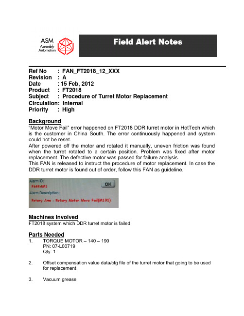
Ref No : FAN_FT2018_12_XXXRevision : ADate : 15 Feb, 2012Product : FT2018Subject : Procedure of Turret Motor ReplacementCirculation: InternalPriority : HighBackground“Motor Move Fail” error happened on FT2018 DDR turret motor in HotTech which is the customer in China South. The error continuously happened and system could not be reset.After powered off the motor and rotated it manually, uneven friction was found when the turret rotated to a certain position. Problem was fixed after motor replacement. The defective motor was passed for failure analysis.This FAN is released to instruct the procedure of motor replacement. In case the DDR turret motor is found out of order, follow this FAN as guideline.Machines InvolvedFT2018 system which DDR turret motor is failedParts Needed1. TORQUE MOTOR – 140 – 190PN: 07-L00719Qty: 12. Offset compensation value data/cfg file of the turret motor that going to be usedfor replacement3. Vacuum greaseProcedure1. Power off the FT2018 system and turn off the air supply. Thendisconnect the motor power cable and encoder cable from the system.2. Connect power cable of new motor and turn on the system. In theDiagnosis Page, checks whether the new motor can be powered on to ensure the motor is not fail.Remark:1. It is important that the motor has to be mounted on bolster platetightly before motivate it or else the whole motor will move around and it is dangerous.2. Turret motor cannot move to home position without loading. It isnormal that you cannot home the new motor without turret disk mounted.3. If the motor can be powered on, you can start the below replacementprocedure after turn off the system and disconnect the new motor. If not, another new motor is needed.4. Loosen the screw at the top of core tube.5. Disconnect the main vacuum hose from the vacuum distributing coretube.Main vacuum hose6. Disconnect the 6 air tubes from the motor base using the tool in thealignment jig box shipped with the system. There are number labels (no.1 to no. 6) on the air tubes. Record the corresponding connected position of air tubes before disconnection from the motor base.Tubes labeled no. 1 to no.3 which supply air for motor cooling Tubes labeled no. 4 to no.6 which let the hot air exhausts out from motorDisconnect the airtubes from the fittingand the jig can gothrough the tube fromone endUse the jig to press thefitting mouth at thebottom of motor todisconnect the air tubes Jig for air tubes disconnectionDistribution of different no.labeled air tubes at themotor bottom.Air tubes(Totally 6 tubes)7. Loosen the 4 screws mounted between bolster plate and core tubes.Then the entire core tube can be pulled down and taken out.Loosen these 4 screws8. Uninstall all the collets to prevent risk of damaging the collets whengetting out the motor.9. Loosen the 12 screws and the 2 dowel pins mounted between the motorand bolster plate.Screws needed to be loosened(totally 12 screws)Dowel pin needed to be takenout (totally 2 dowel pins)Bottom spacer10. Turret motor with turret disk and the bottom spacer underneath canbe moved out together.11. Take out the white color middle disk and then loosen 6 screws at theturret disk.Loosen these 6 screws12. Take out the turret disk and you will see a marked line on the motorrotor. Record down the corresponding pick head no. which aligned with the marked line.13. Remove the motor from the bottom spacer. Use alcohol and air gunto clean the dirt on the spacer and bolster plate.14. Clean the base of the new motor. Place the new motor on the spacer.Install the turret disk with orientation according to the marked line on new motor rotor and the pick head no. recorded down in step 12.15. Use height gauge to check the co-planarity of the turret disk. It shouldbe within 0.06mm. If the co-planarity measured is out of 0.06mm, re-check the assembling process. If the co-planarity is still not within0.06mm after re-assembling, record the co-planarity measurement andfeedback.Continue the procedures.Co-planarity is measuredon the turret edge position16. Install the turret module back by reversing the disassembling process.Remark:The 4 screws mounting the core tube and bolster plate have to befastened first before fasten the screw at the top of core tube.STEP 1 STEP 2 17. Power on the system. Lift up the top disk and add vacuum greasebefore system reset.Add vacuum greasebetween top disk andmiddle disk at A, B, Cregions of the disk18. Each turret motor with its own offset compensation values. Checkwith Production for this. Back up the old cfg file in the path“D:\mc\cfg\Rotary_Arm_HolderOffset.cfg” first and modify the original file with new offset values. Then save the file and restart the “Finish4”program.Modify these offset values for thenew motor19. Fine tune the pick heads and stations alignment with the help ofalignment jig (do the alignment at pos. 6) and the lead vision alignment check software. Feedback the vision log record of different stations after fine tuned.20. Turret motor replacement finished. Ship the failed motor to STJ Chinaoffice through APHK for failure analysis.。
ASMT-MG00-NGJ00 1W Power LED Light Source商品说明书
ASMT-MG00-NGJ00Description1W Power LED Light Source is a high performance energy efficient device which can handle high thermal and high driving current. The exposed pad design has excellent heat transfer from the package to the motherboard.The low profile package design is suitable for a wide variety of applications especially where height is a constraint.The package is compatible with SMT reflow soldering process and manual soldering. This will give more freedom and flexibility to the light source designer.Features•Available in White, Blue, Green color •Energy efficient•Exposed pad for excellent heat transfer •Suitable for SMT process •High current operation •Long operation life •Wide viewing angle •Silicone encapsulationSpecifications•InGaN technology • 3.6 V, 350 mA (typical)•120 viewing angleApplications•Portable (flash light, bicycle head light)•Reading light•Architectural lighting •Garden lighting •Decorative lightingASMT-Mx001 W Power LED Light SourceData SheetPackage DimensionsDevice Selection Guide at Junction Temperature Tj = 25°CMin. Flux Typ. Flux [1]Max. Flux Test Current DiceColor Part Number(lm)(lm)(lm)(mA)Technology Green ASMT-MG00-NGJ0025.54073.0350InGaN Blue ASMT-MB00-NAE00 5.51019.5350InGaN WhiteASMT-MW00-NFI0019.53556.0350InGaNNotes:1.ΦV is the total luminous flux output as measured with an integrating sphere at mono pulse condition.2.Flux tolerance is ± 15 %.213∅ ∅ ANODEANODE NOTES:1. ALL DIMENSIONS IN MILLIMETERS.2. TOLERANCE IS ± 0.1 mm UNLESS OTHERWISE SPECIFIED.CATHODEAbsolute Maximum Ratings at T A = 25°CParameterASMT-Mx00Units DC Forward Current 350mA Peak Pulsing Current [1]500mA Power Dissipation1400mW LED Junction Temperature110°C Operating Board Temperature Range -40 to +85°C Storage Temperature Range -40 to +100°CSoldering TemperatureRefer to Figure 8Note:1. Pulse condition duty factor = 10%, Frequency = 1 kHz.Optical Characteristics (T A = 25 °C)PeakDominant Viewing Angle Luminous Luminous Wavelength Wavelength 2θ1/2 [2]Efficacy,Efficiency λPEAK (nm) λD [1] (nm)(Degrees)ηv [3] (lm/W)(lm/W)Part Number Color Typ.Typ.Typ.Typ.Typ.ASMT- MG00Green 51952512046032ASMT- MB00Blue460467120588ViewingLuminous Luminous Typical Chromaticity Angle 2θ1/2 [2]Efficacy,Efficiency Coordinates (Degrees)ηv [3] (lm/W)(lm/W)Part Number Color x y Typ.Typ.Typ.ASMT-MW00White0.330.3311030028Notes:1.The dominant wavelength, λD , is derived from the CIE Chromaticity Diagram and represents the color of the device.2.θ1/2 is the off-axis angle where the luminous intensity is 1/2 the peak intensity.3.Radiant flux, Φe in watts, may be calculated from the equation Φe = Φv /ηv , where Φv is the luminous flux in lumens and ηv is the luminous efficacy in lumens/watt.Part Numbering SystemASMT-M x 00 – N x x x 0Color Bin Selection Max. Flux Bin Selection Min. Flux Bin Selection Color B – Blue G – Green W – WhiteElectrical Characteristic (T A = 25°C)Forward Voltage V F (Volts) @ I F = 350 mA Reverse Voltage V R [1]Thermal Resistance Rjp (°C/W)Dice Type Typ.Typ.InGaN3.6Not recommended10Note:1. Not designed for reverse bias operation.Figure 1. Relative intensity vs. wavelength Figure 2. Forward current vs. forward voltageFigure 3. Relative luminous flux vs. mono pulse current Figure 4. Radiation patternFigure 5. Maximum forward current vs. ambient temperature Derated based on T J MAX = 110°C, R θJA = 30°C/W / R θJA = 50°C/WFigure 6. Dominant wavelength vs. forward current – InGaN devicesR E L A T I V E I N T E N S I T Y0WAVELENGTH – nm 0.90.61.00.40.30.20.10.50.80.7 F O R W A R D C U R R E N T – m A0FORWARD VOLTAGE – V4.03000.5350 1.01.5200 2.53.03.52.015010050250 R E L A T I V E L U M I N O U S F L U X – l m0MONO PULSE CURRENT – mA 0.90.6501.01001502003002500.43500.30.20.10.50.80.7 D O M I N A N T W A V E L E N G T H –n m100450FORWARD CURRENT – mA400510520200150540530250300490350480470460500 M A X I M U M F O R W A R D C U R R E N T –m A0AMBIENT TEMPERATURE – °C 30035040020015010050250 R E L A T I V E I N T E N S I T Y0OFF-AXIS ANGLE (°)0.90.61.00.40.30.20.10.50.80.7Figure 7. Chromaticity shift vs. current*Note: (x,y) values @ 350 mA reference to (0.0)Figure 8. Recommended reflow soldering profileFigure 9. Recommended soldering land patternTIMET E M P E R A T UR E(Acc. to J-STD-020C)Y -C O O R D I N A T E SX-COORDINATESFlux Bin Limit (for reference only)Flux (lm) at 350 mABin Min.Max.A 5.57.0B7.09.0C9.011.5D11.515.0E15.019.5F19.525.5G25.533.0H33.043.0I43.056.0J56.073.0Tolerance for each bin limits is ±15 %Color Bin LimitsBlue Min. (nm)Max. (nm)A460.0465.0B465.0470.0C470.0475.0D475.0480.0Green Min. (nm)Max. (nm)A515.0520.0B520.0525.0C525.0530.0D530.0535.0Tolerance = ±1 nmColor LimitsWhite(Chromaticity Coordinates)Bin A X0.3670.3620.3290.329Y0.4000.3720.3450.369 Bin B X0.3620.3560.3290.329Y0.3720.3300.3020.345 Bin C X0.3290.3290.3050.301Y0.3690.3450.3220.342 Bin D X0.3290.3290.3110.305Y0.3450.3020.2850.322 Bin E X0.3030.3070.2830.274Y0.3330.3110.2840.301 Bin F X0.3070.3110.2900.283Y0.3110.2850.2650.284 Tolerances ± 0.02Handling PrecautionThe encapsulation material of the product is made of silicone for better reliability of the product. As silicone is a soft material, please do not press on the silicone or poke a sharp object onto the silicone. These might damage the product and cause premature failure. During assembly or handling, the unit should be held on the body (white epoxy).Y -C O O R D I N A T E0.24X-COORDINATE0.360.420.320.300.280.260.340.400.38For product information and a complete list of distributors, please go to our website: Avago, Avago Technologies, and the A logo are trademarks of Avago Technologies Limited in the United States and other countries.Data subject to change. Copyright © 2006 Avago Technologies Limited. All rights reserved.AV01-0239EN June 20, 2006ASMT-MG00-NGJ00。
用于马达控制器的设备配置文件CiA402
说明设备配置文件CiA 402用于马达控制器–CMMS-AS-...-G2–CMMD-AS-...–CMMS-ST-...-G2通过现场总线:–CANopen80401091404NH [8034540]用于马达控制器的设备配置文件CiA 402CMMS-AS/CMMD-AS/CMMS-STCMMS-AS/CMMD-AS/CMMS-ST2Festo –GDCP-CMMS/D-C-CO-ZH –1404NH –原版操作手册的译本GDCP-CMMS/D-C-CO-ZHCANopen ®,CiA ®,DevicecNet ®是商标持有人在相关国家注册的商标。
危险标识和避免危险的提示:警告可能造成重大伤亡的危险。
小心可能造成轻伤或严重财产损失的危险。
其它符号:注意财产损失或功能丧失。
其它文件中的建议、提示、参考。
必需或适用的附件。
环保使用说明。
文本标记:•可按任意顺序进行的工作。
1.应按规定顺序进行的工作。
–一般列举项。
CMMS-AS/CMMD-AS/CMMS-STFesto –GDCP-CMMS/D-C-CO-ZH –1404NH –中文3目录–CMMS-AS/CMMD-AS/CMMS-ST –CiA 4021现场总线接口9............................................................2CANopen 10.................................................................2.1CANopen 标准10............................................................2.2CANopen 接口11............................................................2.2.1连接和显示元件11..................................................2.2.2总线LED 指示灯11................................................2.2.3CAN 针脚分配[X4]11..............................................2.2.4电缆连接注意事项12................................................2.3配置CANopen 线上站点(通过DIP 开关)13..................................2.3.1DIP 开关[S1.1…12]概览14........................................2.3.2Node ID 配置(CAN 地址)14........................................2.3.3配置数据传输率14..................................................2.3.4激活CAN 接口15..................................................2.3.5激活终端电阻15....................................................2.3.6物理单位(换算系数)的设置15......................................2.4CANopen 主站配置16........................................................3CANopen 访问方式17........................................................3.1序言17....................................................................3.2SDO 访问18................................................................3.2.1用于读取和写入的SDO 序列19.......................................3.2.2SDO 故障信息21...................................................3.2.3SDO 访问的仿真22.................................................3.3PDO 消息23................................................................3.3.1对象说明24.......................................................3.3.2PDO 参数设置的对象28..............................................3.3.3激活PDO 32.......................................................3.4SYNC 消息32...............................................................3.5紧急信息33................................................................3.5.1概述33...........................................................3.5.2紧急信息的组成34..................................................3.5.3对象说明34.......................................................CMMS-AS/CMMD-AS/CMMS-ST4Festo –GDCP-CMMS/D-C-CO-ZH –1404NH –中文3.6网络管理(NMT 服务)36....................................................3.6.1Boot-up (Boot-up Protocol)39.....................................3.6.2Start Remote Node 40..............................................3.6.3Stop Remote Node 40...............................................3.6.4Enter Pre-Operational 40..........................................3.6.5Reset Node 41.....................................................3.6.6Reset Communication 41............................................3.6.7Heartbeat (Error Control Protocol)41.............................3.6.8Nodeguarding (Error Control Protocol)42..........................3.7识别码表45................................................................3.8CANopen 处理的内部时间流程45..............................................4设置参数46................................................................4.1加载和存储参数设置46......................................................4.2换算系数(Factor Group)49.................................................4.3输出级参数60..............................................................4.4电流调节器和马达匹配62....................................................4.5调速器66..................................................................4.6位置调节器(Position Control Function)68..................................4.7目标限值76................................................................4.8数字式输入和输出端77......................................................4.9限位开关79................................................................4.10位置采样80................................................................4.11设备信息82................................................................4.12故障管理85................................................................4.13兼容性设置86..............................................................5设备控制(Device Control)88...............................................5.1状态图(State Machine)88..................................................5.1.1概述88...........................................................5.1.2马达控制器的状态图(State Machine)89..............................5.1.3控制字(Control w ord)94...........................................5.1.4读取马达控制器的状态97............................................5.1.5状态字(Status w ords)99...........................................CMMS-AS/CMMD-AS/CMMS-STFesto –GDCP-CMMS/D-C-CO-ZH –1404NH –中文56运行模式104................................................................6.1运行模式的设置104..........................................................6.1.1概述104...........................................................6.1.2对象说明104.......................................................6.2参考运行模式(Homing Mode)106..............................................6.2.1概述106...........................................................6.2.2对象说明107.......................................................6.2.3参考运行过程110....................................................6.2.4参考运行的控制113..................................................6.3定位运行模式(Pro f ile Position Mode)114....................................6.3.1概述114...........................................................6.3.2对象说明115.......................................................6.3.3功能说明118.......................................................6.4同步位置设定(Interpolated Position Mode)121...............................6.4.1概述121...........................................................6.4.2对象说明122.......................................................6.4.3功能说明126.......................................................6.5转速控制运行模式(Pro f ile V elocit y Mode)129................................6.5.1概述129...........................................................6.5.2对象说明131.......................................................6.6转速斜坡133................................................................6.7扭矩控制运行模式(Pro f ile Tor q ue Mode)136..................................6.7.1概述136...........................................................6.7.2对象说明137.......................................................A 诊断信息141................................................................A.1诊断信息的说明141..........................................................A.2含故障排除提示的诊断信息142................................................A.3有关CiA 301/402的故障代码154.............................................CMMS-AS/CMMD-AS/CMMS-ST6Festo–GDCP-CMMS/D-C-CO-ZH–1404NH–中文CMMS-AS/CMMD-AS/CMMS-STFesto –GDCP-CMMS/D-C-CO-ZH –1404NH –中文7当前文件提示本文件介绍了与现场总线接口“版本信息”章节内容相符的马达控制器的设备配置文件CiA 402(DS 402)以及CiA 301的相关信息:–CANopen –集成在马达控制器内的接口[X4]。
莫萨 UC-8100-ME-T系列 IIoT 网关设备介绍说明书

UC-8100-ME-T SeriesArm Cortex-A81GHz IIoT gateway with1mini PCIe expansion slot for a wireless moduleFeatures and Benefits•Armv7Cortex-A81000MHz processor•Dual auto-sensing10/100Mbps Ethernet ports•SD slot for storage expansion•Programmable LEDs and a programmable button for easy installation andmaintenance•Mini PCIe slot for cellular module•Cybersecurity functions•Debian9open platformCertificationsIntroductionThe UC-8100-ME-T computing platform is designed for embedded data acquisition applications.The computer comes with dual RS-232/422/485 serial ports and dual10/100Mbps Ethernet ports,as well as a Mini PCIe socket to support cellular modules.These versatile capabilities let users efficiently adapt the UC-8100-ME-T to a variety of complex communications solutions.The UC-8100-ME-T is built around a Cortex-A8processor that has been optimized for use in energy monitoring systems,but is widely applicable to a variety of industrial solutions.With flexible interfacing options,this tiny embedded computer is a reliable and secure gateway for data acquisition and processing at field sites as well as a useful communications platform for many other large-scale deployments.Wide-temperature and LTE-enabled models are available.All units are thoroughly tested in a testing chamber,guaranteeing that the LTE-enabled computing platforms are suitable for wide-temperature applications.AppearanceSpecificationsComputerCPU Armv7Cortex-A81GHzDRAM UC-8112-ME-T-LX Series:512MB DDR3UC-8112-ME-T-LX1Series:1GB DDR3Storage Pre-installed4GB eMMCPre-installed OS Linux Debian9(kernel v4.4)Computer InterfaceUSB2.0USB2.0hosts x1,type-A connectorsExpansion Slots mPCIe slot x1Number of SIMs1SIM Format MiniButtons Reset buttonEthernet InterfaceEthernet Ports Auto-sensing10/100Mbps ports(RJ45connector)x2 Magnetic Isolation Protection 1.5kV(built-in)LED IndicatorsSystem Power x1SD slots x1Programmable x4Wireless Signal Strength Cellular/Wi-Fi x3Serial InterfaceSerial Ports2x RS-232/422/485Console Port1x4-pin header to DB9console portData Bits5,6,7,8Parity None,Even,Odd,Space,MarkStop Bits1,1.5,2Serial SignalsRS-232TxD,RxD,RTS,CTS,DTR,DSR,DCD,GNDRS-422Tx+,Tx-,Rx+,Rx-,GNDRS-485-2w Data+,Data-,GNDRS-485-4w Tx+,Tx-,Rx+,Rx-,GNDPower ParametersInput Voltage12to36VDCInput Current500mA@12VACPower Consumption6WReliabilityAlert Tools External RTC(real-time clock)Automatic Reboot Trigger External WDT(watchdog timer)Physical CharacteristicsHousing MetalDimensions141x125.6x54.8mm(5.55x4.94x2.15in)Weight550g(1.22lb)Installation DIN-rail mounting,Wall mounting(with optional kit)Environmental LimitsOperating Temperature UC-8112-ME-T-LX/8112-ME-T-LX1:-40to85°C(-40to185°F)UC-8112-ME-T-LX-US-LTE/8112-ME-T-US-LTE-LX1:-40to70°C(-40to158°F) Storage Temperature(package included)-40to85°C(-40to185°F)Ambient Relative Humidity5to95%(non-condensing)Vibration2Grms@IEC60068-2-64,random wave,5-500Hz,1hr per axis(without any USBdevices attached)Shock IEC60068-2-27Standards and CertificationsSafety UL60950-1EMC EN55032/24EMI CISPR32,FCC Part15B Class AEMS IEC61000-4-2ESD:Contact:8kV;Air:15kVIEC61000-4-3RS:80MHz to1GHz:20V/mIEC61000-4-4EFT:Power:4kV;Signal:4kVIEC61000-4-5Surge:Power:1kVIEC61000-4-6CS:10VIEC61000-4-8PFMFGreen Product RoHS,CRoHS,WEEEHazardous Locations Class I Division2MTBFTime535,916hrsStandards Telcordia(Bellcore)StandardWarrantyWarranty Period5yearsDetails See /warrantyPackage ContentsDevice1x UC-8100-ME-T Series computerDocumentation1x quick installation guide1x warranty cardInstallation Kit1x DIN-rail kit(preinstalled)1x power jackDimensionsOrdering InformationModel Name CPU RAM Storage US LTE Module Built-in Operating Temp. UC-8112-ME-T-LX Armv7Cortex-A81GHz512MB4GB eMMC–-40to70°CUC-8112-ME-T-LX-US-Armv7Cortex-A81GHz512MB4GB eMMC✓-40to85°CLTEUC-8112-ME-T-LX1Armv7Cortex-A81GHz1GB4GB eMMC–-40to85°CUC-8112-ME-T-US-LTE-Armv7Cortex-A81GHz1GB4GB eMMC✓-40to70°CLX1Accessories(sold separately)CablesCBL-F9DPF1x4-BK-100Console cable with4-pin connector,1mPower AdaptersPWR-24270-DT-S1Power adapter,input voltage90to264VAC,output voltage24V with2.5A DC loadPower CordsPWC-C7AU-2B-183Power cord with Australian(AU)plug,2.5A/250V,1.83mPWC-C7CN-2B-183Power cord with two-prong China(CN)plug,1.83mPWC-C7EU-2B-183Power cord with Continental Europe(EU)plug,2.5A/250V,1.83mPWC-C7UK-2B-183Power cord with United Kingdom(UK)plug,2.5A/250V,1.83mPWC-C7US-2B-183Power cord with United States(US)plug,10A/125V,1.83mWi-Fi Wireless ModulesWiFi-BGN802.11ac/a/b/g/n Wi-Fi module x1,i-PEX MHF male connector to RP-SMA female connector x2,ANT-WDB-ARM-02x1,M2screw x2AntennasANT-WDB-ARM-02 2.4/5GHz,omni-directional rubber duck antenna,2dBi,RP-SMA(male)ANT-LTEUS-ASM-01GSM/GPRS/EDGE/UMTS/HSPA/LTE,omni-directional rubber duck antenna,1dBiANT-LTE-OSM-06-3m BK MIMO Multi-band antenna that covers700-2700/2400-2500/5150-5850MHz frequencies.Screw-fastenedmounting and full IP67waterproofing are available.ANT-LTE-ASM-05BK LTE stick antenna that covers704-960/1710-2620MHz with a gain of5dBi.ANT-LTE-ASM-04BK LTE Stick antenna that covers704-960/1710-2620MHz providing omnidirectional radiation with a gainof4.5dBi.ANT-LTE-OSM-03-3m BK Multi-band antenna that covers700-2700MHz.Specially designed for2G,3G,and4G applications.Magnetic mounting is available.ANT-GPS-OSM-05-3M BK Active GPS antenna,26dBi,1572MHz,L1band antenna for GPSWall-Mounting KitsUC-8100-ME Wall Mount Kit Wall-mounting kit with screwsDIN-Rail Mounting KitsDK-25-01DIN-rail mounting kit,2screws©Moxa Inc.All rights reserved.Updated Jan21,2020.This document and any portion thereof may not be reproduced or used in any manner whatsoever without the express written permission of Moxa Inc.Product specifications subject to change without notice.Visit our website for the most up-to-date product information.。
- 1、下载文档前请自行甄别文档内容的完整性,平台不提供额外的编辑、内容补充、找答案等附加服务。
- 2、"仅部分预览"的文档,不可在线预览部分如存在完整性等问题,可反馈申请退款(可完整预览的文档不适用该条件!)。
- 3、如文档侵犯您的权益,请联系客服反馈,我们会尽快为您处理(人工客服工作时间:9:00-18:30)。
ASMT-MY00Moonstone TM 1W Power LED Light Source Data SheetDescriptionAvago Technologies’ 1W Warm White Power LED is a high performance energy efficient device which can handle high thermal and high driving current. The exposed pad design has excellent heat transfer from the package to the motherboard.The Warm White Power LED is available in various color temperature ranging from 2600K to 4000K. The product has high Color Rendering Index (CRI) which provides excellent color perception and visual clarity.The package provides an all in all ease of assembly by automated soldering processes. The low package profile is ideal for assemblies with height constraints. Applications•Reading light•Architectural lighting•Garden lighting•Decorative lighting•Specialty lighting Features•Available in Warm White color.•Energy efficient•Exposed pad for excellent heat transfer.•Suitable for reflow soldering process.•High current operation.•Long operation life.•Wide viewing angle.•Silicone encapsulation•Non ESD sensitive•MSL 2ASpecifications•InGaN Technology• 3.6V, 350 mA (Typ.)•110 viewing anglePackage DimensionsDevice Selection Guide at Junction Temperature Tj = 25°CColor Part NumberLuminous Flux, Φv[1, 2] (lm)Test CurrentDice Technology Min Typ Max(mA)Warm White ASMT-MY0043.050.073.0350InGaN Notes:1. ΦV is the total luminous flux output as measured with an integrating sphere at 25ms mono pulse condition.2. Flux tolerance is ±10 %ASMT-M x 00 - N x1 x2 x3 0Color Bin SelectionMax Flux Bin SelectionMin Flux Bin SelectionColorY - Warm WhiteAbsolute Maximum Ratings at T A = 25°CParameter ASMT-MY00Units DC Forward Current [1]350mA Peak Pulsing Current [ ]500mA Power Dissipation1400mW LED Junction Temperature110°C Operating Ambient Temperature Range -40 to +85°C Storage Temperature Range-40 to +100°C Soldering Temperature Refer to figure 6Note:1. DC forward current – derate linearly based on Figure 5.2. Pulse condition duty factor = 10%, Frequency = 1kHz.Part Numbering SystemOptical Characteristics (T A = 25 °C)Part Number Color Correlated Color Temperature,CCT (Kelvin)Viewing Angle2q½[1] (Degrees)Luminous Efficiency(lm/W)Min Max Typ TypASMT-MY00Warm White 600400011040 Notes:1. q½ is the off-axis angle where the luminous intensity is ½ the peak intensity.Electrical Characteristic (T A = 25°C)Dice Type Forward Voltage V F (Volts) @ I F = 350mA Reverse Voltage V R[1]Thermal ResistanceR q j-ms (°C/W)[2] Typ Max.Typ.InGaN 3.6 4.0Not recommended10 Note:1. Not designed for reverse bias operation.2. R q j-ms is Thermal Resistance from LED junction to metal slug.Figure 1. Relative intensity vs. wavelength Figure 2. Forward Current vs Forward VoltageFigure 3. Relative Luminous Flux vs. Mono Pulse Current Figure 4. Radiation PatternFigure 5. Maximum forward current vs. ambient temperatureDerated based on T JMAX = 110°C, R q JA = 30°C/W / 40°C/W and 50°C/W00.10.20.30.40.50.60.70.80.91380430480530580630680730780WAVELENGTH - nm R E L A T I V E I N T E N S I TY0501001502002503003504004505000.000.50 1.00 1.50 2.00 2.50 3.00 3.50 4.00FORWARD VOLTAGE - VF O R W A R D C U R R E N T - m A0.000.200.400.600.801.001.201.40050100150200250300350400450500MONO PULSE CURRENT - mAR E L A T I V E L U M I N O U S F L U X (v ) - l m0.00.10.20.30.40.50.60.70.80.91.0-90-70-50-30-101030507090OFF-AXIS ANGLE (°)R E L A T I V E I N T E N S I TY50100150200250300350400T A AMBIENT TEMPERATURE - °CI M A X F O R W A R D C U R R E N T - m AFFigure 7. Recommended soldering land patternFigure 8. Temperature vs. relative forward voltage shiftFigure 9. Relative LOP vs. junction temperature-200-150-100-50050100150200-40-1510356085TEMPERATURE - °CR E L A T I V E F O R W A R D V O L T A G E S H I F T (m V )102030405060708090100253035404550556065707580859095100105110JUNCTION TEMPERATURE (°C)R E L A T I V E I N T E N S I T Y (%)Figure 6. Recommended Reflow Soldering(Acc. to J-STD-020C)Flux Bin Limit (For reference only) [X1 X2]Bin Flux (lm) at 350mAMin MaxJ43.056.0K56.073.0Tolerance for each bin limits is ±10 %Color Bin Selections [X3]Individual reel will contain parts from one full bin only.0Full DistributionA A onlyB B onlyC C onlyD D onlyE E onlyF F onlyZ A and B onlyY B and C onlyW C and D onlyV D and E onlyU E and F onlyQ A, B and C onlyP B, C and D onlyN C, D and E onlyM D, E and F onlyJ Special Color Bin1A, B, C and D onlyE, F, G and H only3B, C, D and E only4C, D, E and F only5A, B, C, D and E only6B, C, D, E, and F only White Color Limits(Chromaticity Coordinates)White Color Limits(Chromaticity Coordinates)Bin A XY0.450.4340.4880.4470.4700.4140.4380.403 Bin B XY0.4380.4030.4700.4140.450.3840.4 40.376 Bin C XY0.4070.3930.4180.40.450.4340.4380.403 Bin D XY0.3950.360.4070.3930.4380.4030.4 40.376 Bin E XY0.3810.3770.3870.4040.4180.40.4070.393 Bin F XY0.3730.3490.3810.3770.4070.3930.3950.36 Tolerances ±0.010.340.360.380.400.420.440.460.480.500.52X - COORDINATEY-COORDINATEPackage Tube DimensionsHandling PrecautionThe encapsulation material of the product is made of silicone for better reliability of the product. As silicone is a soft material, please do not press on the silicone or poke a sharp object onto the silicone. These might damage the product and cause premature failure. During assembly or handling, the unit should be held on the body (white epoxy). Moisture SensitivityThis products is classified as moisture sensitive level 2A When the bag is opened, parts required to mount within672 hours of factory conditions ≤30°C/60%, and stored at <10% RH.Devices required bake, before mounting if:a) The humidity indicator card is >10% when read at 23±5°Cb) The pack has been opened for more than 672 hours. Baking recommended condition: 60±5°C for 20 hours.DISCLAIMER: AVAGO’S PRODUCTS AND SOFTWARE ARE NOT SPECIFICALLY DESIGNED, MANUFACTURED OR AUTHORIZED FOR SALE AS PARTS, COMPONENTS OR ASSEMBLIES FOR THE PLANNING, CONSTRUCTION, MAINTENANCE OR DIRECT OPERATION OF A NUCLEAR FACILITY OR FOR USE IN MEDICAL DEVICES OR APPLI-CATIONS. CUSTOMER IS SOLELY RESPONSIBLE, AND WAIVES ALL RIGHTS TO MAKE CLAIMS AGAINST AVAGO OR ITS SUPPLIERS, FOR ALL LOSS, DAMAGE, EXPENSE OR LIABILITY IN CONNECTION WITH SUCH USE.For product information and a complete list of distributors, please go to our web site: Avago, Avago Technologies, and the A logo are trademarks of Avago Technologies in the United States and other countries.Data subject to change. Copyright © 005- 008 Avago Technologies. All rights reserved.AV0 -05 EN - July , 008。