接键盘读卡器控制器_V50说明书
一体化远距离读卡器说明书
远距离读卡器说明书此说明书将指导您如何使用读卡器。
请在使用读卡器前,仔细阅读此说明书。
一、产品概述随着社会现代化进程的不断推进,人们不断追求高品质生活,汽车已逐步成为人们出行的交通工具。
车辆的迅猛发展给传统的手动刷卡停车场管理系统也带了巨大压力。
上、下班高峰期排队等候刷卡、上坡车道停车刷卡、雨雪天气伸手刷卡等有诸多不便。
科技的发展,先进技术的应用,也更好的解决了传统产品的不足。
远距离不停车自动感应产品的诞生,以便捷、减排、省时、节油等传统产品无法比拟的优势,将全面取代传统式手工刷卡的停车场系统。
因停车场系统应用的特殊性,并不是任何一款远距离读卡设备都能发挥应有的功能,在实际应用中信号能否穿透汽车隔热膜、相临车道信号干扰、跟车信号干扰、微波辐射危害、信号衰减、电磁兼容等关键技术成为产品稳定性的重要因素。
我公司生产的定向远距离读卡器利用红外和微波同步通讯技术,充分考虑产品在停车场系统和ETC系统应用的特点,是国内目前唯一能解决准确定位和互相干扰的远距离读卡设备。
二、产品性能三、系统原理该款远距离定向读卡器结合了红外与射频通讯特点,互补两个不同频率通道的工作优势,相互进行信息传递。
射频是一个无方向的电磁波,难以准确定向,但通讯速度快;而红外具有严格的角度定位,但通讯速度慢;在停车场实际应用中选用某一个通道通讯难以达到理想的使用要求。
原理:读卡器发射60度红外扫描信号,红外信号是经过加密的数据,包含了唤醒编码、机器编码信息;当休眠中的远距离卡进入读卡器发送的红外信号范围时,立即被唤醒工作,发射射频电磁波发送远距离卡内码,在发送卡内码的同时也将读卡器机器码附带传递给读卡器;读卡器接收到卡号后对首先对机器码验证,与该机身码相符的为有效卡直接上传给上位机,与该机器码不符的直接删除,避免了临近车道和跟车的串号干扰。
四 、产品特点⑪穿透性:可穿透任何金属汽车防爆膜,远距离卡放置到车内,无需摇窗户可自动识别感应; ⑫方向性:采用红外定位射频传输双通道模式方式工作,具有严格的方向性和稳定性,读卡区60度以外绝不读卡。
usb数据采集卡使用说明书V50(新驱动)
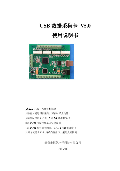
USB数据采集卡 V5.0使用说明书USB2.0 总线,与计算机隔离8路输入通道同步采集,可实时采集传输8路单端模拟量采集,2路DA模拟量输出2路PWM可编程频率占空比输出1路PWM频率脉宽测量,1路32位计数器端口8 路单向输入口/8 路单向输出口,采用光耦隔离新郑市恒凯电子科技有限公司2015/10在开始使用前请仔细阅读下面说明检查打开包装请查验如下:¾USB数据采集卡 V5.0一块;¾高屏蔽USB数据传输电缆一根;保修本产品自售出之日起一年内,用户遵守储存、运输和使用要求,而产品质量不合要求,凭保修单免费维修。
因违反操作规定和要求而造成损坏的,需缴纳器件费及相应的运输费用,如果板卡有明显烧毁、烧糊情况原则上不予维修。
如果板卡开箱测试有问题,可以免费维修(限购买板卡10天内)。
软件支持服务自销售之日起提供6个月的免费开发咨询。
目录一、 USB 数据采集卡V5.0 说明 (1)1.1 板卡简介 (1)1.2 软件支持 (2)1.3 应用领域 (2)1.4 售后服务 (2)二、性能指标 (3)2.1 USB总线性能 (3)2.2 模拟信号输入 (3)2.3 模拟信号输出 (3)2.4 数字信号输入/输出 (3)2.5 PWM测量输入 (4)2.6 计数器 (4)2.7 PWM输出 (4)2.8、工作温度 (4)三、安装与连接 (5)3.1 安装 (5)3.1.1 关于USB (5)3.1.2 USB延长线 (5)3.2 信号连接注意事项 (5)3.4 端子定义及排序说明 (6)3.4 板子尺寸 (7)3.5 各类信号链接方式 (7)四、软件的安装与使用 (10)4.1 驱动的安装与软件的使用 (10)4.1.1 驱动的安装 (10)4.1.2 软件的使用 (12)4.2 接口函数说明 (16)4.2.1 设备操作函数 (16)4.2.2 AD操作函数概况 (17)4.2.3 其它输入输出操作函数 (20)4.2.4 多板卡同时使用相关函数 (23)4.2.5 过采样及相关说明 (24)五、客户程序使用采集卡教程 (28)5.1 VC编程教程 (28)5.2 编程教程 (28)5.3 LABVIEW编程教程 (29)5.4 Labwidows/CVI (32)一、 USB 数据采集卡V5.0 说明恒凯电子-USB数据采集卡采用USB2.0高速总线接口,总线极具易用性,即插即用,是便携式系统用户的最佳选择,可以完全取代以往的PCI卡。
kodak i5x50系列扫描仪使用手册说明书

Kodaki5x50 Series ScannersUser's GuideUser's Guide on Installation CD Guide d'utilisation sur le CD d'installation Benutzerhandbuch auf der Installations-CD Manuale per l'utente sul CD di installazione Gufa del usuario en el CD de instalaci6n Guia do Usuario no CD de instalac;:ao Gebruikershandleiding op installatie-cd Kurulum CD'sindeki Kullarnm Kdavuzu Uzivatelska pi'irucka na instalacnfm disku CD��,'ti!A:.t.�.lf.lF:tliii¥i �ltJ'tlit.t. � { �.If.I :ff :tlii i¥i} 4/A�-J�CDO).:Z.--+f-.:;(:tj-{ !-: �xi CD.2.I Ar§ ��A-l �'--'"'WI .1.�I '--'"'_;ill csk �\ J,l.i PyKOBO,QCTBO nonb3osaren� Ha ycraHOB04HOM KOMnaKT-,Q\11CKe Ghidul utilizatorului de pe CD-ul de instalare Felhasznal6i utmutat6 a telepit6 CD-n KODAK i5250 ScannerKODAK i5250V ScannerKODAK i5650 ScannerKODAK i5650V ScannerKODAK i5850 Scanner第三方许可证This software is based in part on the work of the Independent JPEG GroupCopyright (C)2009-2013 D. R. Commander. All Rights Reserved.Redistribution and use in source and binary forms, with or without modification, are permitted provided that the following conditions are met:-Redistributions of source code must retain the above copyright notice, this list of conditions and the following disclaimer.-Redistributions in binary form must reproduce the above copyright notice, this list of conditions and the following disclaimer in the documentation and/or other materials provided with the distribution.-Neither the name of the libjpeg-turbo Project nor the names of its contributors may be used to endorse or promote products derived from this software without specific prior written permission.THIS SOFTWARE IS PROVIDED BY THE COPYRIGHT HOLDERS AND CONTRIBUTORS "AS IS", AND ANY EXPRESS OR IMPLIED WARRANTIES, INCLUDING, BUT NOT LIMITED TO, THE IMPLIED WARRANTIES OF MERCHANTABILITY AND FITNESS FOR A PARTICULAR PURPOSE ARE DISCLAIMED. IN NO EVENT SHALL THE COPYRIGHT HOLDERS OR CONTRIBUTORS BE LIABLE FOR ANY DIRECT, INDIRECT, INCIDENTAL, SPECIAL, EXEMPLARY, OR CONSEQUENTIAL DAMAGES (INCLUDING, BUT NOT LIMITED TO, PROCUREMENT OF SUBSTITUTE GOODS OR SERVICES; LOSS OF USE, DATA, OR PROFITS; OR BUSINESS INTERRUPTION) HOWEVER CAUSED AND ON ANY THEORY OF LIABILITY, WHETHER IN CONTRACT, STRICT LIABILITY, OR TORT (INCLUDING NEGLIGENCE OR OTHERWISE) ARISING IN ANY WAY OUT OF THE USE OF THIS SOFTWARE, EVEN IF ADVISED OF THE POSSIBILITY OF SUCH DAMAGE.目录1 概览 (1)支持文档 (2)附件 (2)包装箱内的物品 (3)扫描仪组件 (4)正面视图:所有机型 (4)正面视图:i5850 和 i5850S 型扫描仪 (6)打印机正面检修口视图:所有机型 (7)打印机后部检修口视图 (7)内部视图:所有机型 (8)背面视图:i5250/i5250V/i5650/i5650V/i5650S 型扫描仪 (9)背面视图:i5850 和 i5850S 型扫描仪 (10)2 安装 (11)安装扫描仪 (11)安装柯达驱动程序软件 (11)安装输出托盘:i5x50/i5x50V 型扫描仪 (12)安装输出托盘:i5650S/i5850S 型扫描仪 (12)连接电源线和 USB 电缆:i5250/i5250V/i5650/i5650V/i5650S 型扫描仪 (12)连接电源线和 USB 电缆:i5850/ i5850S 型扫描仪 (13)打开扫描仪电源 (14)电源模式 (16)3 扫描 (17)准备扫描仪以进行扫描 (17)调整输入升降台 (17)安装可选文档扩展器 (19)调整输出托盘 (19)更换悬吊件扩展板(i5250、i5250V、i5650、i5650V 或 i5850) (21)安装短文档适配器 (21)调整扫描仪的高度(仅限 i5850/i5850S 型扫描仪) (22)使用背面文档出口 (22)安装背面文档出口托盘附件 (23)准备好要进行扫描的文档 (24)扫描文档 (25)暂停和恢复扫描 (26)使用操作员控制面板触摸屏 (26)“就绪”屏幕 (27)清理纸张路径 (28)降低升降台 (28)切换计数器 (28)背面出口 (29)查看操作员日志 (29)查看扫描仪信息 (29)诊断 (30)查看扫描历史记录 (30)查看维护计量表 (30)执行测试打印件 (32)执行自检 (33)仅计数 (33)仅计数 - 重张进纸 (34)仅计数 - 分类选项 (34)仅计数 - 简单分类 (35)仅计数 - 条形码分类 (35)仅计数 - 补充码分类 (35)执行补充码测试 (36)执行补充码读取器测试 (36)执行 UDDS 校准 (37)执行触摸屏校准 (37)变更 (37)在扫描应用程序中启用“索引编排”之后出现“就绪”屏幕(仅限 i5650/i5650S/i5850/i5850S 型扫描仪) (38)验证重张进纸文档 (39)从文档卡纸恢复 (40)“设置”屏幕 (41)用户计数器 (42)自动升降器 (42)订书钉/金属防护 (42)更该警报音量 (43)选择声音 (43)度量单位 (44)错误进纸 OCP 控制 (44)双堆叠切换补充码 (44)覆盖 (45)应用程序覆盖 (46)选择语言 (47)打印 (47)最大长度检测 (48)自动开始扫描 (48)文档处理 (49)纸张来源 (49)扫描后旋转选项 (50)错误进纸检测 (50)扫描速度 (50)重叠进纸检测 (51)重张进纸传感器 (51)更改打印偏移 (52)双堆叠 (52)重置所有设置 (53)4 打印文档 (55)打印机规格 (56)安装/更换墨盒 (57)访问正面打印机 (57)访问背面打印机(i5850 和 i5850S) (58)访问背面打印机 (i5250/i5250V/i5650/i5650V/i5650S) (58)安装墨盒 (58)更改打印位置 (60)在前部和后部打印托架之间移动墨盒 (61)安装/更换吸墨条状纸(仅限正面打印机) (62)问题解决方案 (63)调整 i5650S 和 i5850S 型扫描仪的输出托盘 (65)调整上部托盘的角度 (66)调整上部托盘或背面文档出纸口托盘的侧导板 (67)取下背面出纸口托盘 (67)使用悬吊件 (68)题解决方案 - i5650S 和 i5850S 型扫描仪 (68)受控的双堆叠附件(i5650S 或 i5850S 中不提供) (70)堆叠位置 (70)建议的配置 (70)建议的纸张规格 (71)为纵向扫描启用长度保护 (71)可靠堆叠的提示 (72)调整可控双堆叠附件 (72)调整堆叠 1 和堆叠 2 的侧导板 (73)短文档插入板 (73)调整终端挡板 (74)撤销可控双堆叠 (74)双堆叠切换补充码 (74)问题解决方案 - 受控的双堆叠附件 (75)6 补充码读取 (77)补充码页面是什么? (77)何处读取补充码页面? (78)补充码要求 (80)颜色切换补充码 (80)补充码图案详细信息 (81)条形图案详细信息 (84)补充码定位 (87)纸张详细信息 (87)7 维护 (89)清洁频率表 (89)清洁工具和材料 (90)打开扫描仪护盖 (90)清洁程序 (91)用真空吸尘器清洁输出托盘和输入升降台 (91)清洁滚筒 (92)清洁分离滚筒滚轮 (92)清洁进纸模组滚轮 (93)清洁可翻转白色背景条 (93)清洁成像导轨 (94)运行传送器清洁纸 (94)最终清洁步骤 (94)更换程序 (95)更换进纸模组或进纸模组滚轮 (95)更换分离滚筒或分离滚筒滚轮 (99)更换预分纸垫片 (100)更换成像导轨 (100)更换可翻转白色背景条 (101)补给品与耗材 (102)问题解决方案 (103)电源按钮/指示灯 (105)升级软件 (105)请联系服务中心 (105)附录 A 规格 (107)系统要求 (108)附录 B 保修 - 仅适用于美国和加拿大 (109)安全用户预防措施•将桌面型扫描仪置于坚固且可支撑 57.6 千克(127 磅;或仅对于 i5650S 型号,65 千克/144 磅)的水平工作面上,并在扫描仪各边留出足够的空隙。
智能读卡器用户手册

附录:读卡器与电控锁专用电源盒、信源中控系统连接图注意:本讲台采用全钢结构,为了使用安全,请务必将讲台进行可靠接地处理,强烈建议安装漏电保护器。
感谢您选用信源产品,为了您更好地使用本产品,请仔细阅读本手册。
专用遥控器) ⊕极(绿线)⊖极(蓝线))网络控制器一、设置管理卡拉出安装有读卡器的讲台抽屉,用小木棒按下抽屉侧面读卡器设置孔内的按钮2秒以上,此时读卡器前面板上绿色LED 指示灯闪亮,蜂鸣器发出2长1短的叫声,表示进入设置功能。
在绿色指示灯闪亮的10秒内将您的ID 卡插入读卡器内,读卡器读到卡后蜂鸣器发出1短声,绿色指示灯自动熄灭,说明该张ID 卡已设置成管理卡。
注意:有些ID 卡片内感应线圈偏向一边,因此,当将ID 卡插入读卡器如无反应时,请换个方向插。
管理卡只能是1张,如果丢失或更换,将新卡按以上方法重新设置,新管理卡生效后,原管理卡就自动失效。
※ 除了管理卡的设置外,其余设置都必须在刷管理卡后才能进行操作 ※二、添加用户卡如果您需要给ID 卡授权,通过添加用户卡的操作来进行(您最大可以添加1000张用户卡),设置都需用管理卡+专用红外遥控器配合进行:插入管理卡,绿色指示灯闪亮,读卡器发出嘟1声,读卡器进入设置状态,拔出管理卡,用遥控器对准读卡器插卡口按一下按键【3】后再按一下【*】键,读卡器发出嘟嘟2声,进入设置添加用户卡功能,将未授权的ID 卡插入读卡器,嘟1声后说明这张卡已添加,需要添加第2张卡,这时只要将第2张卡插入,随后再发出嘟1声,第2张卡添前面板双色指示灯红:电源指示 绿:设置指示加完成,如此重复将所有需要授权的用户卡添加完成。
刷管理卡或按一下遥控器【*】键,嘟嘟2声结束添加。
读卡器在20秒内没有添加用户卡,蜂鸣器嘟嘟嘟3声,绿色指示灯熄灭,读卡器也将自动退出设置状态,进入正常工作方式。
在添加用户卡时蜂鸣器响3声表示该卡已存在,此时为重复添加。
蜂鸣器响4短声表示卡数量已满,不能再添加。
Micro SD 卡读卡器说明书
了解您的手机飞利浦将不断力争改善产品性能并确保该用户指南的准确性。
因为手机软件版本的更新,本手册中的某些内容可能与您的手机有所差异。
飞利浦保留修改本用户指南的权利,如有更改,恕不另行通知。
请以手机实际操作为准。
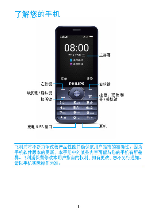
主屏幕耳机右软键挂断、取消和开/关机键左软键导航键/确认键接听键充电/USB 接口待机屏待机屏由以下部分组成:按键了解主要按键如何操作。
功能(拨号拨打或接听电话。
,确认及导航键选择或确认菜单功能。
)挂机/退出/开关机结束通话; 返回待机屏;长按开启/关闭手机。
L 左软键选取屏幕上的对应选项。
R右软键选取屏幕上的对应选项。
*键盘锁在待机屏,长按*锁定键盘;或先按L ,再按* 锁定键盘或为键盘 解锁。
图标行快捷菜单图标与符号了解显示屏上显示的图标。
静音来电时手机会静音。
振动来电时手机会振动。
电池指示条显示电量状态。
短信您收到一条新短信。
未接电话您有一个未接电话。
耳机耳机已接连到手机。
GSM网络手机已连接到GSM 网络。
指示条越多,接收质量越好。
GPRS连接手机已连接到GPRS网络。
第一次使用安装与充电首次使用手机时,如何安装SIM卡及给手机充电。
插入SIM卡234为电池充电新电池已部分充电,手机屏幕上的电池图标表示电量状态。
插入Micro SD卡(存储卡)提示:•充电时,您仍可以使用手机。
•电池完全充电后,将充电器继续连接在手机上不会损坏电池。
如需关闭充电器,应将其从电源上拔下。
因此,请选择易于您插拔的插座。
•如果您几天内都不会使用手机,建议您取出电池。
•如果已完全充电的电池搁置不用,电池本身在一段时间后,会因自放电而处于无电压或低电压状态。
•新电池或长时间未使用的电池,需要较长时间充电。
您可在手机中插入Micro SD卡以 扩展手机存储容量。
将Micro SD卡与卡槽对齐并放入卡槽。
使用您的手机如何拨打电话拨出电话1输入电话号码。
2按(拨打该号码。
3按)挂机。
提示:•如需拨打国际长途电话,长按0输入国际前缀“+”。
指纹读卡器用户手册说明书

指纹读卡器用户手册版权所有©杭州海康威视数字技术股份有限公司2019。
保留一切权利。
本手册的任何部分,包括文字、图片、图形等均归属于杭州海康威视数字技术股份有限公司或其子公司(以下简称“本公司”或“海康威视”)。
未经书面许可,任何单位和个人不得以任何方式摘录、复制、翻译、修改本手册的全部或部分。
除非另有约定,本公司不对本手册提供任何明示或默示的声明或保证。
关于本手册本手册描述的产品仅供中国大陆地区销售和使用。
本手册作为指导使用。
手册中所提供照片、图形、图表和插图等,仅用于解释和说明目的,与具体产品可能存在差异,请以实物为准。
因产品版本升级或其他需要,本公司可能对本手册进行更新,如您需要最新版手册,请您联系我们。
海康威视建议您在专业人员的指导下使用本手册。
商标声明为海康威视的注册商标。
本手册涉及的其他商标由其所有人各自拥有。
责任声明●在法律允许的最大范围内,本手册所描述的产品(含其硬件、软件、固件等)均“按照现状”提供,可能存在瑕疵、错误或故障,本公司不提供任何形式的明示或默示保证,包括但不限于适销性、质量满意度、适合特定目的、不侵犯第三方权利等保证;亦不对使用本手册或使用本公司产品导致的任何特殊、附带、偶然或间接的损害进行赔偿,包括但不限于商业利润损失、数据或文档丢失产生的损失。
●若您将产品接入互联网需自担风险,包括但不限于产品可能遭受网络攻击、黑客攻击、病毒感染等,本公司不对因此造成的产品工作异常、信息泄露等问题承担责任,但本公司将及时为您提供产品相关技术支持。
●使用本产品时,请您严格遵循适用的法律。
若本产品被用于侵犯第三方权利或其他不当用途,本公司概不承担任何责任。
如本手册内容与适用的法律相冲突,则以法律规定为准。
前言本节内容的目的是确保用户通过本手册能够正确使用产品,以避免操作中的危险或财产损失。
在使用此产品之前,请认真阅读产品手册并妥善保存以备日后参考。
概述本手册适用于指纹读卡器,适用型号如下:符号约定对于文档中出现的符号,说明如下所示。
HID OmniSmart 5100 读卡器连接线接头说明书
CE MarkingHID Global hereby declares that these proximity readers are in compliance with the essential requirements and other relevant provisions of Directive 2014/53/EU.Por el presente, HID Global declara que estos lectores de proximidad cumplen con los requisitos esenciales y otras disposiciones relevantes de la Directiva 2014/53/EU.HID Global déclare par la présente que ces lecteurs à proximité sont conformes aux exigences essentielles et aux autres stipulations pertinentes de la Directive 2014/53/EU.A HID Global, por meio deste, declara que estes leitores de proximidade estão em conformidade com as exigências essenciais e outras condições da diretiva 2014/53/EU.HID Global bestätigt hiermit, dass die Leser die wesentlichen Anforderungen und anderen relevanten Bestimmungen der Richtlinie 2014/53/EU erfüllen.HID Global dichiara che i lettori di prossimità sono conformi ai requisiti essenziali e ad altre misure rilevanti come previsto dalla Direttiva europea 2014/53/EU.Download copies of the Radio Equipment Directive Declaration of Conformity (DoC) at: /certificationsTaiwan根據NCC低功率電波輻射性電機管理辦法 規定:第十二條 經型式認證合格之低功率射頻電機,非經許可,公司、商號或使用者均不得擅自變更頻率、加大功率或變更原設計之特性及功能。
V50说明书

上图为 CyberScan Vantage 50 搭配 LT9010 型号激光光学传感器时设备图
6
4. 设备功能用途说明
CyberScan Vantage 50 激光非接触式二维或三维测量系统广泛在微电子和其他 精密工业中大量应用,CyberScan 的 Vantage 50 整合了激光光学技术和电脑控 制的工作平台移动技术,使 Vantage 50 在没有工装夹具的实际限制下,能达到 最大的弹性应用范围。对小的被测物体可以简单的直接放置于可移动传感器的下 面进行测量。CyberScan 的 Scan CT 应用软件提供了全面的广泛的二维/三维轮 廓测量,使 Vantage 50 可以测量高度、长度、宽度、面积、弧度、粗糙度、倾
在激光光学传感器聚焦的情况下设定起点位置(Start)、终点位置(End)和马达 扫描步距(Step),步距设定越小量测精度越高,步距设定越大则精度越差,故 需按实际量测物品情况设定合适的步距(建议 5um)。
3.以上量测起点和终点及量测步距都设定好了后,点击量测键
进行扫
描量测。设备会进行自动量测并产生所量测位置的二维剖面曲线图出来,此时我 们需点选 Analyse 分析功能菜单介面。
我们的非接触式三维测量系统广泛应用于微电子和其他精密工业中大量应 用,包括台阶高度测量、轮廓测量、粗糙度测量、平整度测量、太阳能电池的测 量等。我们的解决方案得到大型国际公司信任,以及许多中小型企业应用于研发 和生产。并在全球构建了完善的合格代理商或分销商网络。为我们的客户提供全 方位的技术运用支持。 cybertechnologies 是一个强大的全球高精度测量系统 设备制造商,值得全球客户信任。
Y 方向最大扫描长度 50 mm 基于 2um 步距时 Y 轴测量速度为 1 mm / sec Y 轴最小马达移动步距为 1um
羅技BKB50藍牙鍵盤使用手冊说明书

使用手冊藍牙™ 鍵盤基礎 (3)總覽 (3)鍵盤概覽 (3)為鍵盤充電 (4)開啟及關閉 (5)開始使用 (6)設定鍵盤 (6)組裝 (6)使用您的藍牙™ 鍵盤 (8)丹麥和挪威使用者的平板電腦設定 (8)電腦鍵盤啟動器應用程式 (8)使用電腦鍵盤啟動器 (8)使用觸控板 (9)睡眠模式 (10)重設鍵盤 (11)Web提供的支援 (11)法律資訊 (12)Declaration of Conformity (13)總覽BKB50藍牙™ 鍵盤可協助您以使用電腦的方式使用Xperia™ Z4平板電腦,而且方便您在外出時使用。
您可以使用NFC功能,輕鬆地將藍牙™ 鍵盤與平板電腦配對。
一旦藍牙™ 鍵盤設定完成並連接至平板電腦,便可偵測到平板電腦關機的動作,並且還能視需要關閉以節省電量。
鍵盤概覽1平板電腦專用凹槽2充電連接埠3通知指示燈4配對鍵5電源切換鍵6觸控板鍵盤控制按鍵符號按鍵組合功能Fn + F1降低亮度。
Fn + F2提高亮度。
Fn + F3降低音量。
Fn + F4提高音量。
Fn + F5移至上一個音訊或影片檔案。
Fn + F6播放或暫停目前使用的音訊或影片檔案。
Fn + F7移至下一個音訊或影片檔案。
Fn + F8開啟USB偵測功能以偵測連線的USB裝置。
Fn + F9剪下Fn + F10複製Fn + F11貼上Fn + F12搜尋開啟通知面板列印畫面開啟或關閉畫面。
上述清單僅顯示組合鍵控制和其他一些常用的按鍵。
上面未列出的其他按鍵均可透過與大多數鍵盤相同的方式操作。
通知指示燈狀態閃藍燈鍵盤正處於配對模式,可與其他裝置進行配對。
白燈鍵盤正處於使用中模式。
閃白燈鍵盤正處於睡眠模式。
綠燈電池正在充電,電量已超過90%。
琥珀色燈電池正在充電,電量介於15%和90%之間。
紅燈電池正在充電,但電量低於15%。
為鍵盤充電為鍵盤充電第一次使用鍵盤前,請先充電四小時。
僅限使用標準充電器。
1將Android手機或平板電腦的充電器插入電源插座。
CTV50说明书

纽曼C T V50使用手册Ver 8.14您好感谢您选用本公司生产的产品!本品为手持电视,可支持多种音频、视频、图片的浏览;还可随意的扩展空间,给您带来完美的便携影音播放世界。
播放设置更加人性化,足以体现您的个性风采,满足您的娱乐需求。
在使用本品之前,请仔细阅读我们随机提供的所有资料,本手册将为您介绍它的功能,使您在使用过程中更加轻松方便。
通过它您可以获取有关产品介绍、使用方法等方面的知识,以便您能更好地使用该产品。
在编写本手册时我们非常认真和严谨,希望能给您提供完备可靠的信息,然而难免有错误和疏漏之处,请您给予谅解并由衷地欢迎您批评和指正。
如果您在使用该产品的过程中发现什么问题,请及时拨打我们的服务热线,感谢您的支持与合作!请随时备份您的数据资料到您的计算机上。
本公司对于因软件、硬件的误操作、产品维修、电池更换或其它意外情况所引起的个人数据资料的丢失和损坏不负任何责任,也不对由此而造成的其它间接损失负责。
同时我们无法控制用户对本手册可能造成的误解,因此,本公司将不对在使用本手册过程中可能出现的意外损失负责,并不对因使用该产品而引起的第三方索赔负责。
本手册的信息以当前产品情况为准。
我们将继续开发提供新的功能,相关信息的更新恕不另行通知。
本手册信息受到版权保护,任何部分未经本公司事先书面许可,不准以任何方式影印和复制。
●产品及产品颜色款式请以购买的实物为准。
●本公司保留对本手册、服务手册及其相关资料的最终解释权。
企业执行标准:Q/BATB004-2010 企业标准备案:2010007使用注意事项★禁止儿童单独玩耍本机,请勿摔落或与硬物摩擦撞击,否则可能导致机器表面磨花、硬盘损伤、数据丢失或其它硬件损坏。
★建议不要大音量连续使用耳机,请将音量调整至合适的音量大小,并控制使用时间,以避免您的听力受损。
因为使用耳机时如果音量过大,可能导致永久性的听力损伤。
★请不要试图分解或改造本机,这样可能导致电击或妨碍产品质保。
IPAD五合一读卡器的使用方法

IPAD五合一读卡器的使用方法请各位亲们仔细阅读使用方法,说明里有写的,客服不再做后续介绍,本店三款读卡器均支持IPAD1,IPAD2,支持目前最新系统IOS5.0目录IPAD未越狱使用方法及注意事项-----------------------------(第2-3页)IPAD已越狱使用方法及注意事项----------------------------(第4-6页)IPAD未越狱使用方法及注意事项1.支持USB连接相机,直接读取相机里面的照片;2.支持SD/TF/MC/MMC/M2五种卡,必须有DCIM文件夹,里面有相机拍的照片,其它照片不行;TF卡插下面的小孔,金属向上,推到底;3.支持键盘,必须耗电量低于20AH,大部分键盘都可以;4.支持U盘,必须耗电量低于20AH,要建立DCIM文件夹,里面有相机拍的照片;其它照片不行;总结:未越狱主要用于相机和SD/TF/M2/MMC/MS卡,键盘和U盘不太适用,硬盘更不要期望,亲可以去威锋网找相关的贴子,本店不做这类售后~常见问题:1.插到IPAD上面为什么没有反应?原因一:插上读卡器,在IPAD桌面-设置-通用-关于本机-调制解调器固件下方会出来一行英文,如果有的话,读卡器则是正常的,如果没有,可能是IPAD 带着皮套或者后壳之类挡到读卡器导致接触不到的原因。
把皮套去掉重新启动IPAD(因为反复插拨有时候会不识别),再接上读卡器,看下有没有英文,如果还是没有,非常抱歉,这是我们产品的质量问题,请联系在线客服帮你更换,运费我们负责的,亲无需担心,耽误您的使用,请您原谅!原因二:右侧附有开关,使用USB和读卡功能时需要切换,不能同时使用;原因三:如果使用的卡是直接从相机取下来的,请看下是不是卡的位置没有插好,如果使用的卡不是相机里面的,看下是不是没有建立DCIM文件夹,卡是不是FAT32格式的。
原因四:如果使用的U盘,U盘需要是FAT32格式的,一定要有DCIM文件夹,文件夹里面要有相机拍的照片,其它照片不行解决方法:把IPAD关机重启,先插上读卡器,开关打到读卡或者USB功能,接上卡或者相机,等10秒,会弹出相册。
导航V50安装配置手册

海信商海导航V5.0安装说明海信安装盘说明:目录或者文件名用途说明[ADO] ADO之MDAC2.7版本安装目录[AppSetup] 商海导航应用程序安装目录[MSDESetup] 供便利店安装数据库使用的MSDE数据库安装目录[DBSetup] 商海导航数据库安装目录[驱动程序] 包含各种其他硬件的驱动程序目录[使用手册] 各种操作手册及使用说明书———————————————————————————————————————安装准备:操作系统要求:建议安装中文Windows 2000 sp4或XP sp3以上版本操作系统网络配置:配置各工作站网卡、网络用户以及网络协议等,使系统中各台收款机、各台计算机可以互相访问(一)海信商海导航程序安装开始:1.打开安装程序盘[AppSetup]目录,运行Setup.exe文件2.更改安装路径为:D:\hisense\xpos5\ ,确定,执行下一步直至安装完成3.将最新补丁文件拷贝至安装目录:D:\hisense\xpos5\,覆盖安装目录下现有文修的、程序安装完成安装后桌面会生成快捷图标,仅保留以下图标:后台程序前台收银(二)前后台配置①配置后台程序:双击商海导航后台管理V5.0图标按下图进行数据库设置:配置完成后,即可登陆至后台程序。
②配置前台程序:设置收款机计算机名称与后台收款机站点设置中的工作站名称一致。
双击商海导航前台收款V5.0图标运行前台程序01.安装完成后首次运行会弹出下图对话框,设置服务器IP地址,如是单店且前后台在同一台机器上,则设置为地址为127.0.0.1, 端口号:1111 。
请在此处填写业务服务器IP,如:172.16.10.1 , 默认为本机IP地址127.0.0.1。
02. 安装完成后首次运行可使用xsa 用户登陆,密码为空。
03. 选择管理功能菜单。
04. 按下面步骤完成收款机设置, 只需完成第一步和第二步红色方框处设置, 其它参数可通过后台服务器下载到收款机。
IPAD五合一读卡器的使用方法
IPAD五合一读卡器的使用方法IPAD五合一读卡器的使用方法请各位亲们仔细阅读使用方法,说明里有写的,客服不再做后续介绍,本店三款读卡器均支持IPAD1,IPAD2,支持目前最新系统IOS5.0目录IPAD未越狱使用方法及注意事项-----------------------------(第2-3页)IPAD已越狱使用方法及注意事项----------------------------(第4-6页)IPAD未越狱使用方法及注意事项1.支持USB连接相机,直接读取相机里面的照片;2.支持SD/TF/MC/MMC/M2五种卡,必须有DCIM文件夹,里面有相机拍的照片,其它照片不行;TF卡插下面的小孔,金属向上,推到底;3.支持键盘,必须耗电量低于20AH,大部分键盘都可以;4.支持U盘,必须耗电量低于20AH,要建立DCIM文件夹,里面有相机拍的照片;其它照片不行;总结:未越狱主要用于相机和SD/TF/M2/MMC/MS卡,键盘和U盘不太适用,硬盘更不要期望,亲可以去威锋网找相关的贴子,本店不做这类售后~常见问题:1.插到IPAD上面为什么没有反应?原因一:插上读卡器,在IPAD桌面-设置-通用-关于本机-调制解调器固件下方会出来一行英文,如果有的话,读卡器则是正常的,如果没有,可能是IPAD 带着皮套或者后壳之类挡到读卡器导致接触不到的原因。
把皮套去掉重新启动IPAD(因为反复插拨有时候会不识别),再接上读卡器,看下有没有英文,如果还是没有,非常抱歉,这是我们产品的质量问题,请联系在线客服帮你更换,运费我们负责的,亲无需担心,耽误您的使用,请您原谅!原因二:右侧附有开关,使用USB和读卡功能时需要切换,不能同时使用;原因三:如果使用的卡是直接从相机取下来的,请看下是不是卡的位置没有插好,如果使用的卡不是相机里面的,看下是不是没有建立DCIM文件夹,卡是不是FAT32格式的。
原因四:如果使用的U盘,U盘需要是FAT32格式的,一定要有DCIM文件夹,文件夹里面要有相机拍的照片,其它照片不行解决方法:把IPAD关机重启,先插上读卡器,开关打到读卡或者USB功能,接上卡或者相机,等10秒,会弹出相册。
balluff-btl7-v50d-m-产品-使用指南说明书

BTL7-V50D-M _ _ _ _ -A/B/Y/Z(8)-C003 BTL7-V50E-M _ _ _ _ -A/B/Y/Z(8)-C003 BTL7-V50T-M _ _ _ _ -A/B/Y/Z(8)-C003deutschKurzanleitungi shCondensed guideenglNotice résuméei sfrançaIstruzioni brevii tali anoInstrucciones breves español中文简明指南1Der Wegaufnehmer bildet zusammen mit einer Maschinen-steuerung (z. B. SPS) ein Wegmesssystem. Er wird zu seiner Verwendung in eine Maschine oder Anlage einge-baut und ist für den Einsatz im Industriebereich vorgese-hen. Die einwandfreie Funktion gemäß den Angaben in den technischen Daten wird nur mit original Balluff Zubehör zugesichert, die Verwendung anderer Komponenten bewirkt Haftungsausschluss.Das Öffnen des Wegaufnehmers oder eine nichtbestim-mungsgemäße Verwendung sind nicht zulässig und führen zum Verlust von Gewährleistungs- und Haftungsansprü-chen gegenüber dem Hersteller.Die Installation und die Inbetriebnahme sind nur durch geschultes Fachpersonal zulässig.Der Betreiber hat die Verantwortung, dass die örtlich geltenden Sicherheitsvorschriften eingehalten werden. Insbesondere muss der Betreiber Maßnahmen treffen, dass bei einem Defekt des Wegmesssystems keine Gefah-ren für Personen und Sachen entstehen können.Bei Defekten und nichtbehebbaren Störungen des Weg-aufnehmers ist dieser außer Betrieb zu nehmen und gegen unbefugte Benutzung zu sichern.Eine ausführliche Betriebsanleitung und die Konfigurations-anleitung erhalten Sie im Internet unter oder per E-Mail bei ******************.Im Wegaufnehmer befindet sich der Wellenleiter geschützt durch ein Edelstahlrohr. Entlang des Wellenleiters wird ein Positionsgeber bewegt. Dieser Positionsgeber ist mit dem Anlagenbauteil verbunden, dessen Position bestimmt werden soll.Die Beschreibungen der LED-Anzeigen sind der ausführlichen Betriebsanleitung zu entnehmen.ACHTUNGFunktionsbeeinträchtigungUnsachgemäße Montage kann die Funktion des Wegauf-nehmersbeeinträchtigen und zu erhöhtem Verschleiß führen.►Die Anlagefläche des Wegaufnehmers muss vollstän-dig an der Aufnahmefläche anliegen.►Die Bohrung muss perfekt abgedichtet sein (O-Ring/Flachdichtung).Wegaufnehmer mit dem Befestigungsgewinde in das Einschraubloch eindrehen (Drehmoment max. 100 Nm).Bei waagerechter Montage mit Nennlängen > 500 mm ist der Stab abzustützen und gegebenenfalls am Ende anzu-schrauben (nur bei Ø 10,2 mm möglich).Beim Einbau in Hydraulikzylinder darf der Positionsgeber nicht auf dem Stab schleifen. Minimaler Bohrungsdurch-messer im Aufnahmekolben:deutschMit dem CE-Zeichen bestätigen wir, dass unsere Produkte den Anforderungen deraktuellen EMV-Richtlinie entsprechen.File No.E227256 2N r. 910169 D E ∙ L 16; Än d e r u n g e n v o r b e h a l t e n . E r s e t z t F 14.deutschInbetriebnahme1. Anschlüsse auf festen Sitz und richtige Polung prüfen.Beschädigte Anschlüsse tauschen.2. System einschalten.3. Messwerte prüfen (insbesondere nach dem Austauschdes Wegaufnehmers oder der Reparatur durch den Hersteller). Gegebenenfalls den Wegaufnehmer neu einstellen.Das Einstellverfahren ist in der ausführlichen Betriebsanleitung beschrieben.Hinweise zum Betrieb–Funktion des Wegmesssystems und aller damit ver-bundenen Komponenten regelmäßig überprüfen. –Bei Funktionsstörungen das Wegmesssystem außerBetrieb nehmen.–Anlage gegen unbefugte Benutzung sichern.Schirmung und KabelverlegungDefinierte Erdung!Wegaufnehmer und Schaltschrank müssen auf dem gleichen Erdungspotenzial liegen.SchirmungZur Gewährleistung der elektromagnetischen Verträglich-keit (EMV) sind folgende Hinweise zu beachten:–Wegaufnehmer und Steuerung mit einem geschirmtenKabel verbinden.Schirmung: Geflecht aus Kupfer-Einzeldrähten, Bede-ckung mindestens 85 %.–Steckerausführung: Schirm im Steckverbinder mit demSteckergehäuse flächig verbinden.MagnetfelderDas Wegmesssystem ist ein magnetostriktives System. Auf ausreichenden Abstand des Wegaufnehmers und des Aufnahmezylinders zu starken externen Magnetfeldern achten.KabelverlegungKabel zwischen Wegaufnehmer, Steuerung und Stromver-sorgung nicht in der Nähe von Starkstromleitungen verle-gen (induktive Einstreuungen möglich). Kabel zugentlastet verlegen.KabellängeBei Verwendung von CAT5e-Kabel beträgt die maximale Kabellänge 100 m 3).3) Voraussetzung: durch Aufbau, Schirmung und Verlegung keine Einwir-kung fremder Störfelder.Pinbelegung Steckverbinder (Draufsicht auf Stecker am Wegaufnehmer)1) Nicht belegte Adern können steuerungsseitig mit GND verbunden werden, aber nicht mit dem Schirm.2) Bezugspotenzial für Versorgungs s pannung und EMV-GND.1The Transducer, together with a machine controller (e.g. PLC), comprises a position measuring system. It is intended to be installed into a machine or system and used in the industrial sector. Flawless function inaccordance with the specifications in the technical data is ensured only when using original Balluff accessories. Use of any other components will void the warranty.Opening the transducer or non-approved use are notpermitted and will result in the loss of warranty and liability claims against the manufacturer.Installation and startup may only be performed by trained specialists.The operator is responsible for ensuring that local safety regulations are observed. In particular, the operator must take steps to ensure that a defect in the positionmeasuring system will not result in hazards to persons or equipment.If defects and unresolvable faults occur in the transducer, it should be taken out of service and secured against unauthorized use.A complete user’s guide and the configuration guide can be downloaded from the Internet at or requested via e-mail from ******************.The transducer contains the waveguide which is protected by an outer stainless steel tube (rod). A magnet is moved along the waveguide. This magnet is connected to the system part whose position is to be determined.The descriptions of the LED displays can be found in the comprehensive user’s guide.NOTICE!Interference in functionImproper installation can compromise the function of the transducer and result in increased wear.►The mounting surface of the transducer must makefull contact with the supporting surface.►The bore must be perfectly sealed (O-ring/flat seal).Screw the transducer thread into the mounting hole (max. torque 100 Nm).For horizontal assembly with nominal lengths > 500 mm, support the rod and tighten it at the end if necessary (only possible with a diameter of 10.2 mm).If installed in a hydraulic cylinder, the magnet should not make contact with the rod. Minimum bore diameter in thesupport piston:englishThe CE Mark verifies that our products meet the requirements of the currentEMC Directive.File no.E227256 2N o . 910169 E N ∙ L 16; S u b j e c t t o m o d i fi c a t i o n . R e p l a c e s F 14.englishStartup1. Check connections for tightness and correct polarity.Replace damaged connections.2. Turn on the system.3. Check measured values (especially after replacing thetransducer or after repair by the manufacturer). Recalibrate the transducer, if necessary.The calibration procedure is described in the comprehensive user’s guide.Operating notes–Check the function of the transducer and all associatedcomponents on a regular basis.–Take the position measuring system out of operationwhenever there is a malfunction.–Secure the system against unauthorized use.Shielding and cable routingDefined ground!The transducer and the control cabinet must be at the same ground potential.ShieldingTo ensure electromagnetic compatibility (EMC), observe the following:–Connect the transducer and controller using a shieldedcable.Shielding: Copper filament braided, at least 85% coverage.–Connector version: Shield is internally connected toconnector housing.Magnetic fieldsThe position measuring system is a magnetostrictive system. It is important to maintain adequate distance between the transducer cylinder and strong, external magnetic fields.Cable routingDo not route the cable between the transducer, controller, and power supply near high voltage cables (inductive stray noise is possible). The cable must be routed tension-free.Cable lengthThe maximum cable length when using CAT5e cables is 100 m 3).3) Prerequisite: Construction, shielding and routing preclude the effect of any external noise fields.Pin assignment of connector (view of connector pins of transducer)1) Unassigned leads can be connected to GND on the controller side but not to the shield.2) Reference potential for supply voltage and EMC-GND.1Couplé à une commande de machine (p. ex. API), lecapteur de déplacement constitue un système de mesure de déplacement. Il est monté dans une machine ou une installation et est destiné aux applications dans le domaine industriel. Son bon fonctionnement, conformément aux indications figurant dans les caractéristiques techniques, n’est garanti qu’avec les accessoires d’origine de Balluff, l’utilisation d’autres composants entraîne la nullité de la garantie.Tout démontage du capteur de déplacement ou toute utilisation inappropriée est interdit et entraîne l’annulation de la garantie et de la responsabilité du fabricant.L’installation et la mise en service ne doivent être effectuées que par un personnel qualifié.Il est de la responsabilité de l’exploitant de veiller à ce que les dispositions locales concernant la sécurité soient respectées. L’exploitant doit en particulier prendre les mesures nécessaires pour éviter tout danger pour les personnes et le matériel en cas de dysfonctionnement du système de mesure de déplacement.En cas de dysfonctionnement et de pannes du capteur de déplacement, celui-ci doit être mis hors service et protégé contre toute utilisation non autorisée.Une notice d’utilisation détaillée et des instructions concernant la configuration sont disponibles sur le site internet ou sur demande par courriel à ******************.Le capteur de déplacement abrite le guide d’ondes, qui est protégé par un tube en acier inoxydable. Un capteur de position se déplace le long du guide d’ondes. Le capteur de position est relié à l’élément de l’installation dont la position doit être déterminée.Les affichages à LED sont décrits en détail dans la notice d’utilisation.ATTENTIONLimitations de fonctionnementUn montage incorrect peut limiter le bon fonctionnement du capteur de déplacement et entraîner une usure prématurée.►La surface d’appui du capteur de déplacement doitparfaitement couvrir la surface de réception. ►Le perçage doit être parfaitement étanche (jointtorique / plat).Visser le capteur de déplacement avec le filetage de fixation dans le trou de vissage (couple de serrage 100 Nm).En cas de montage horizontal avec des longueursnominales > 500 mm, la tige doit être soutenue et, le cas échéant, vissée à l’extrémité (uniquement possible pour Ø 10,2 mm).En cas de montage dans un vérin hydraulique, le capteur de position ne doit pas frotter contre la tige. Diamètre deperçage minimal dans le piston de réception :françaisAvec le symbole CE, nous certifions que nos produits répondent auxexigences de la directive CEM actuelle. 2N ° 910169 F R ∙ L 16 ; s o u s r és e r v e d e m o d i fi c a t i o n s . R e m p l a c e F 14.françaisMise en service1. Vérifier la fixation et la polarité des raccordements.Remplacer les raccordements endommagés.2. Mettre en marche le système.3. Vérifier les valeurs (en particulier après remplacementdu capteur de déplacement ou réparation par le fabricant). Le cas échéant, procéder à un nouveau réglage du capteur de déplacement.La procédure de réglage est décrite dans la notice d’utilisation détaillée.Conseils d’utilisation–Contrôler régulièrement les fonctions du capteur dedéplacement et de tous ses composants.–En cas de dysfonctionnement, mettre le système horsservice.–Protéger le système de toute utilisation non autorisée.Blindage et pose des câblesMise à la terre définie !Le capteur de déplacement et l’armoireélectrique doivent être reliés au même potentiel de mise à la terre.BlindagePour garantir la compatibilité électromagnétique (CEM), les consignes suivantes doivent être respectées :–Le capteur de déplacement et la commande doiventêtre reliés par un câble blindé : tresse de fils de cuivre, couverture minimum 85 %.–Modèle de connecteur : relier à plat le blindage duconnecteur au boîtier de connecteur.Champs magnétiquesLe système de mesure de déplacement est un système magnétostrictif. Veiller à ce que le capteur de déplacement et le vérin de réception se trouvent à une distance suffisante de champs magnétiques externes de forte intensité.Pose des câblesNe pas poser le câble reliant le capteur de déplacement, la commande et l’alimentation à proximité d’un câble haute tension (possibilités de perturbations inductives). Ne poser le câble que lorsque celui-ci est déchargé de toute tension.Longueur de câbleLa longueur maximale pour un câble CAT5e est de 100 m 3).3) Condition préalable : la structure, le blindage et le câblage excluent toute influence de champs perturbateurs externes.Affectation des broches du connecteur (vue de dessus sur le connecteur du capteur de déplacement)1) Les conducteurs non utilisés peuvent être reliés coté commande à la masse GND, mais pas au blindage.2) Potentiel de référence pour tension d’alimentation et GND CEM.1Il trasduttore di posizione Micropulse costituisce insieme a un comando macchina (per es. PLC) un sistema di misura della corsa. Per poter essere utilizzato, il trasductore deve essere montato su una macchina o su un impianto ed è destinato all’impiego in ambiente industriale. Ilfunzionamento corretto secondo le indicazioni dei dati tecnici è garantito soltanto con accessori originali Balluff, l’uso di altri componenti comporta l’esclusione della responsabilità.L’apertura o l’uso improprio del trasduttore di posizione non sono consentiti e determinano la decadenza di qualsiasi garanzia o responsabilità da parte della casa produttrice.L’installazione e la messa in funzione sono consentite soltanto da parte di personale specializzato addestrato.Il gestore ha la responsabilità di far rispettare le norme di sicurezza vigenti localmente. In particolare il gestore deve adottare provvedimenti tali da poter escludere qualsiasi rischio per persone e cose in caso di difetti del sistema di misura della corsa.In caso di difetti e guasti non eliminabili del trasduttore di posizione questo deve essere disattivato e protetto contro l’uso non autorizzato.Per il manuale d’uso dettagliato e le istruzioni per la configurazione consultare in Internet l’indirizzo o inviare un’e-mail a ******************.Nel trasduttore di posizione si trova la guida d’onda,protetta da un tubo in acciaio inox. Lungo la guida d’onda viene spostato un datore di posizione. Questo datore di posizione è collegato al componente dell’impianto del quale deve essere determinata la posizione.Le descrizioni dei display LED sono riportate nel manuale d’uso dettagliato.ATTENZIONEAnomalie funzionaliIl montaggio non corretto può ostacolare ilfunzionamento del trasduttore di posizione e provocare una maggiore usura.►La superficie di appoggio del trasduttore di posizionedeve poggiare completamente sulla superficie di alloggiamento.►Il foro deve essere perfettamente chiuso a tenuta(O-ring/guarnizione piatta).Avvitare il trasduttore di posizione con la filettatura di fissaggio nel foro di avvitamento (coppia max. 100 Nm).Per un montaggio orizzontale con lunghezze nominali > 500 mm, la barra va sostenuta ed eventualmente avvitata all’estremità (possibile solo per Ø 10,2 mm)Durante il montaggio nel cilindro idraulico il datore di posizione non deve sfregare contro la barra. Diametrominimo del foro nel pistone di alloggiamento:italianoIl marchio CE è la conferma che i nostri prodotti sono conformi ai requisitidell'attuale Direttiva EMC.File No.E227256 2N . 910169 I T ∙ L 16; c o n r i s e r v a d i a p p o r t a r e m o d i fi c h e . S o s t i t u i s c e F 14.italianoMessa in funzione1. Controllare che i collegamenti siano fissati saldamentee che la loro polarità sia corretta. Sostituire i collegamenti danneggiati.2. Attivare il sistema.3. Controllare i valori misurati (in particolare dopo lasostituzione del trasduttore di posizione o la riparazione da parte della casa produttrice). Eventualmente regolare nuovamente il trasduttore di posizione.La procedura di regolazione è descritta nel manuale d’uso dettagliato.Avvertenze per il funzionamento–Controllare periodicamente il funzionamento delsistema di e di tutti i componenti ad esso collegati. –In caso di anomalie di funzionamento disattivare ilsistema di misura della corsa.–Proteggere l’impianto da un uso non autorizzato.Schermatura e posa dei caviMessa a terra definita!Il trasduttore di posizione e l’armadio elettrico devono trovarsi sullo stesso potenziale di terra.SchermaturaPer garantire la compatibilità elettromagnetica (CEM) è necessario rispettare le seguenti avvertenze:–Collegare il trasduttore di posizione e l’unità di controllocon un cavo schermato.Schermatura: maglia di singoli fili di rame, copertura almeno 85%.–Esecuzione del connettore: collegare la schermaturanel connettore con il corpo del connettore sull’intera superficie.Campi magneticiIl sistema di misura della corsa è un sistemamagnetostrittivo. Mantenere una distanza sufficiente del trasduttore di posizione e del cilindro sul quale è montato dai campi magnetici esterni intensi.Posa dei caviNon posare i cavi fra il trasduttore di posizione, il comando e l’alimentazione elettrica in prossimità di linee ad alta tensione (sono possibili interferenze induttive). Posare il cavo senza tensione.Lunghezza dei caviSe si utilizzano cavi CAT5e la lunghezza massima dei cavi è di 100 m 3).3) Premessa: la struttura, la schermatura e la posa devono essere tali da impedire l’influenza di campi di disturbo esterni.Piedinatura del connettore (vista in pianta del connettore sul trasduttore di posizione)1) I fili non utilizzati possono essere collegati con GND lato controllo, ma non con la schermatura.2) Potenziale di riferimento per tensione di alimentazione e CEM-GND.(presa)1El transductor de desplazamiento forma un sistema de medición de desplazamiento junto con un control de máquina (por ejemplo, PLC). Para utilizarlo, se monta en una máquina o instalación y está previsto para el uso en la industria.El funcionamiento óptimo según las indicaciones que figuran en los datos técnicos sólo se garantiza con accesorios originales de Balluff; el uso de otroscomponentes provoca la exoneración de responsabilidad.No se permite la apertura del transductor dedesplazamiento o un uso indebido. Ambas infracciones provocan la pérdida de los derechos de garantía y de exigencia de responsabilidades ante el instalación y la puesta en servicio sólo se permiten a personal técnico cualificado.El explotador es responsable de respetar las normas de seguridad locales vigentes. En particular, el explotador debe adoptar medidas destinadas a evitar peligros para las personas y daños materiales si se produce algún defecto en el sistema de medición de desplazamiento.En caso de defectos y fallos no reparables en eltransductor de desplazamiento, éste se debe poner fuera de servicio e impedir cualquier uso no autorizado.Obtendrá un manual de instrucciones detallado y el manual de configuración en la página de Internet o por correo electrónico escribiendo a ******************.En el transductor de desplazamiento se encuentra el guíaondas, protegido mediante un tubo de aceroinoxidable. A lo largo del guíaondas se mueve un sensor de posición. Este sensor de posición está unido con el componente de la instalación cuya posición se desea determinar.Las descripciones de los indicadores LED se pueden consultar en el manual de instrucciones detallado.ATENCIÓNMerma del funcionamientoUn montaje indebido puede mermar el funcionamiento del transductor de desplazamiento y causar un mayor desgaste. ►La superficie de contacto del transductor dedesplazamiento debe coincidir completamente con la superficie de alojamiento.►El orificio debe estar perfectamente hermetizado(junta tórica/junta plana).Enrosque el transductor de desplazamiento con la rosca de fijación en el agujero roscado (par máx. 100 Nm).En caso de montaje horizontal con longitudes nominales > 500 mm, la varilla debe apoyarse y, dado el caso, atornillarse en el extremo (solo posible con Ø 10,2 mm).En el montaje en un cilindro hidráulico, el sensor de posición no debe rozar la varilla. Diámetro mínimo delorificio en el pistón de alojamiento:españolCon el marcado CE confirmamos que nuestros productos cumplen con los requerimientosde la directiva CEM actual.File No.E227256BTL7-V50D/E/T -M _ _ _ _ -A/B/Y/Z(8)-C003Transductor de desplazamiento — forma constructiva de varilla 2N .° 910169 E S ∙ L 16; r e s e r v a d o e l d e r e c h o a m o d i fi c a c i o n e s . S u s t i t u y e F 14.españolPuesta en servicio1. Compruebe que las conexiones estén asentadasfirmemente y tengan la polaridad correcta. Sustituya las conexiones dañadas.2. Conecte el sistema.3. Compruebe los valores de medición (sobre tododespués de sustituir el transductor de desplazamiento o de repararlo el fabricante). Dado el caso necesario, reajuste el transductor de desplazamiento.El procedimiento de ajuste está descrito en el manual de instrucciones detallado.Indicaciones sobre el servicio–Compruebe periódicamente el funcionamiento delsistema de medición de desplazamiento y todos los componentes relacionados.–Si se producen fallos de funcionamiento, ponga fuerade servicio el sistema de medición de desplazamiento. –Asegure la instalación contra cualquier uso no autorizado.Blindaje y tendido de cablesPuesta a tierra definidaEl transductor de desplazamiento y el armario eléctrico deben estar a idéntico potencial de puesta a tierra.BlindajePara garantizar la compatibilidad electromagnética (CEM), se deben tener en cuenta las siguientes indicaciones:–Conecte el transductor de desplazamiento y el controlcon un cable blindado.Blindaje: malla de hilos individuales de cobre, cobertura mínima del 85 %.–Ejecución de conector: conecte superficialmente elblindaje en el conector con la carcasa del mismo.Campos magnéticosEl sistema de medición de desplazamiento es un sistema magnetostrictivo. Preste atención a que exista suficiente distancia entre el transductor de desplazamiento y el cilindro de alojamiento y campos magnéticos externos intensos.Tendido de cablesNo tienda los cables entre el transductor dedesplazamiento, el control y la alimentación de corriente cerca de líneas de alta tensión (posibilidad deperturbaciones inductivas). Tienda los cables descargados de tracción.Longitud de cableSi se utilizan cables CAT5e, la máxima longitud de cable es de 100 m 3).3) Requisito: no deben intervenir campos parasitarios externos a consecuencia del montaje, blindaje y tendido.BTL7-V50D/E/T -M _ _ _ _ -A/B/Y/Z(8)-C003Transductor de desplazamiento — forma constructiva de varillaAsignación de pines del conector (vista desde arriba del conector en el transductor de desplazamiento)1) Los conductores no utilizados se pueden conectar en el lado del control con GND, pero no con el blindaje.2) Potencial de referencia para la tensión de alimentación y CEM-GND.1外置式位感器与设备控制器(例如PLC)组成使用规定一套行程测量系统。
接键盘读卡器控制器_V50说明书
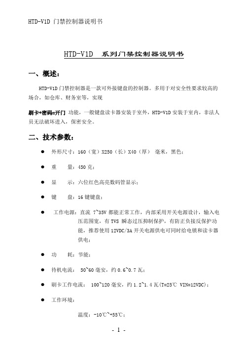
HTD-V1D 系列门禁控制器说明书一、概述:HTD-V1D门禁控制器是一款可外接键盘的控制器。
多用于对安全性要求较高的场合,如仓库、财务室等,实现刷卡+密码=开门功能,一般键盘读卡器安装于室外,HTD-V1D安装于室内,非法人员无法破坏进入,保密安全。
二、技术参数:●外形尺寸:160(宽)X250(长)X40(厚)毫米,黑色;●重量:450克;●显示:六位红色高亮数码管显示;●键盘:16键键盘;●工作电源:直流 7~35V 都能正常工作,内部采用开关电源设计,输入电压范围宽,有TVS 瞬态过压抑制保护,有防正负接反保护功能,推荐使用12VDC/3A开关电源供电可同时给电锁和读卡器供电;●功耗:节能;●待机电流: 50~60毫安,约0.6~0.7瓦;●刷卡工作电流: 100~120毫安,约1.2~1.4瓦(T=25℃ VIN=12VDC);●工作环境:温度:-10℃~+55℃;湿度:0%~90%RH;线路板100%防潮处理;●多路输出:一路继电器输出控制门锁,一路报警OC门输出;●多路输入:门磁监控,红外线监控,手动放行,消防联动输入等,每路输入都加有光电隔离保护;●通讯接口:标准RS485方式,波特率:4800~19200BPS,加有TVS瞬态过压抑制及防雷管和共模抑制保护,确保通讯接口电路安全;●读卡器接口:标准维根输入接口,光电隔离保护;●用户数量:1700人(可根据用户需求增加);●记录容量:保持最新记录 6144 条(可根据用户需求增加);●外部掉电记录保持时间:8750小时;●功能强大:支持多种开门方式,完善的进入时段管理,可脱机工作,环境监控,支持多种电锁,详细记录;●配套管理软件功能强大。
三、系统操作:1. 系统密码为了系统的安全,避免非系统管理人员随意修改系统参数,我们设置了系统密码来加以防范,即进入系统设定各项功能时,必须先输入正确的系统密码确认,方允许操作,出厂初始密码为“000000”。
SALICRU CV50系列LCD键盘操作手册说明书

The manual is for SALICRU LCD keypad, which supports English and Spanish displaying. It can be used with CV50 inverter.Refer to the operational manual of CV50 inverter for details.¡Connect only to CV50 inverters. Using this keypad withother series might damage the inverter!Dimension of the keypadDimension of the LCD keypad(unit:mm)KeypadThe keypad is used to read the state data and adjust parameters.Fig KeypadSerialNo.Name Description1 StateLCDRUN/TUNELED off means that the inverter is inthe stopping state; LED blinking meansthe inverter is in the parameterautotune state; LED on means theinverter is in the running state.FWD/REVFWD/REV LCDLED off means the inverter is in theforward rotation state; LED on meansthe inverter is in the reverse rotationstateLOCAL/REMOTLED for keypad operation, terminalsoperation and remote communicationcontrolLED off means that the inverter is inthe keypad operation state; LEDblinking means the inverter is in theterminals operation state; LED onmeans the inverter is in the remotecommunication control state.SerialNo.Name DescriptionTRIPLED for faultsLED on when the inverter is in the faultstate; LED off in normal state; LEDblinking means the inverter is in thepre-alarm state.2CodedisplayingzoneLCD displaying.Display the information of the function code.The current state will be displayed on the upper right ofthe LCD in the editing state: E stand for fault state, Sstands for stopping state and R stands for running state.3 ButtonsProgrammingkeyEnter or escape from thefirst level menu andremove the parameterquicklyEntry keyEnter the menustep-by-stepConfirm parametersUP keyIncrease data or functioncode progressivelyDOWN keyDecrease data orfunction codeprogressivelyRight-shiftkeyMove right to select thedisplaying parametercircularly in stopping andrunning mode.Select the parametermodifying digit duringthe parametermodificationRun keyThis key is used tooperate on the inverterin key operation modeStop/Reset keyThe function isdetermined by thefunction codeRefer to the operationalmanual ofcorresponding inverterfor detailsQuick keyThe function isdetermined by thefunction codeRefer to the operationalmanual ofcorresponding inverterfor detailsKeypad displayingThe keypad displaying is divided into stopping state parameter, runningstate parameter and fault state and so on.Keypad setting and menu selectionPress SHIFT and DOWN key for 3 seconds at the same time after power onand then the menu selection mode is displayed as below:1. Hardware test: tests of the keys, screen and indicators;2. Flash date program: used only when the FLASH configuration table isupdated;3. Language select: language selection (English and Spanish mode);4. Keypad SW version: view the MCU and Flash Software version;5. Inverter select: select CV50.Displayed state of stopping parameterWhen the inverter is in the stopping state, the keypad will display stopping parameters which is shown in figure.In the stopping state, various kinds of parameters can be displayed. Select the parameters to be displayed or not by “parameter selection for the stopping state”(Refer to the operational manual of CV50 inverter for details.》/SHIFT can shift the parameters form left to right, QUICK/JOG(Refer to the operational manual of CV50 inverter for details) can shift the parameters form right to left.Displayed state of running parametersAfter the inverter receives valid running commands, the inverter will enter into the running state and the keypad will display the running parameters. RUN/TUNE LCD on the keypad is on, while the FWD/REV is determined by the current running direction which is shown as figure.In the running state, various kinds of parameters can be displayed. Select the parameters to be displayed or not by “parameter selection for the running state”(Refer to the operational manual of CV50 inverter for details).》/SHIFT can shift the parameters form left to right, QUICK/JOG(Refer to the operational manual of corresponding inverter for details) can shift the parameters from right to left. Displayed state of faultIf the inverter detects the fault signal, it will enter into the fault displaying state. The keypad will display the fault code by flicking. The TRIP LCD on the keypad is on, and the fault reset can be operated by the STOP/RST on the keypad, control terminals or communication commands.Displayed state of function codes editingIn the state of stopping, running or fault, press PRG/ESC to enter into the editing state (Refer to the operational manual of CV50 inverter for the password).The editing state is displayed on two classes of menu, and the order is: function code group/function code number→function code parameter, press DATA/ENT into the displayed state of function parameter. On this state, you can press DATA/ENT to save the parameters or press PRG/ESC to retreat.Keypad operationOperate the inverter via operation panel. See the detailed structure description of function codes in the brief diagram of function codes.The inverter has three levels menu, which are:1. Group number of function code (first-level menu).2. Tab of function code (second-level menu).3. Set value of function code (third-level menu).Remarks: Press both the PRG/ESC and the DATA/ENT can return to the second-level menu from the third-level menu. The difference is: pressing DATA/ENT will save the set parameters into the control panel, and then return to the second-level menu with shifting to the next function codeautomatically; while pressing PRG/ESC will directly return to the second-level menu without saving the parameters, and keep staying at the current function code.Under the third-level menu, if the parameter has no flickering bit, it means the function code cannot be modified. The possible reasons could be:1) This function code is not modifiable parameter, such as actual detected parameter, operation records and so on;2) This function code is not modifiable in running state, but modifiable in stop state.。
CPRM读卡器软件sd-jukebox v5中文使用说明书

• 将音频 CD 录制到您的计算机 ..................... 12 • 自动录制 CD .........................................................................13 • 使用 SD-Jukebox 播放音乐 ........................ 14
4
开始
欢迎使用 SD-Jukebox
SD-Jukebox 是一个应用程序,可以在您的计算机上录制和管理音频 CD 上的音乐。SD-Jukebox 也可以使您将录制的曲 目 “卸载”到 SD 记忆卡上,这样您就可以在 SD 音频播放机或其它 SD 设备 (本说明书统称为 “SD 播放机”)上欣 赏音乐。
5
开始
系统要求
为了使用 SD-Jukebox,您的计算机需要满足下列要求。
兼容的个人计算机:与 IBM PC/AT 兼容的个人计算机且预装了下列操作系统之一
操作系统:Microsoft® Windows® 2000 (Professional SP2, 3, 4) Microsoft® Windows® XP (Home Edition/Professional,或者支持的 SP1, 2)
硬件
中央处理器: Intel® Pentium® III 500 MHz 或更高
内存:
256 MB 或更多
可用硬盘空间: 100 MB 或更多 (依据 Windows 的版本或音频数据,会需要追加更多的可用硬盘空间。)
显示器:
韦根接口读卡器说明书

PAR-100A读卡器使用说明书1. 性能指标:性能指标说明频率13.56MHz使用卡型Mifare 系列卡,如S50、S70、华虹SHC1102读卡范围≥6cm读卡时间<0.1秒输出格式Wiegand18~Wiegand58可设工作电压DC9V~DC15V工作电流60mA工作温度-20℃~55℃工作湿度15%~90%2. 接线说明:接线顔色接线标号说明红色+12V +12V输入黑色GND 地线绿色DATA0 Wiegand格式DATA0白色DATA1 Wiegand格式DATA1紫线BZ 蜂鸣器,报警信号输出,低电平响蓝色LED 指示灯,低电平绿灯亮棕色NC 保留黄色NC 保留注意:1)电源必须是稳压电源,系统必须有单独的接地点2)控制器与读卡器之间的线缆应使用线径大于2mm的屏蔽双绞线3)控制器与读卡器之间的连线长度小于80米3. 读卡器工作状态:1)读卡器通电后,红灯亮、蜂鸣器响。
未初始化的韦根读卡器:蜂鸣器响1秒;已初始化的韦根读卡器:蜂鸣器响1声长(半秒),两声短(每声四分之一秒)。
2)读卡器正常工作划卡时,蜂鸣器响1声(四分之一秒)。
读卡器出厂默认值为Wiegand26,脉冲宽度为100us,脉冲周期为1ms。
3)读卡器具有挂起功能,卡片在有效读卡距离内只被读取一次。
4. 安装注意事项:1)因为读卡器发射频率为13.56MHz,所以在读卡器安装现场不得有13MHz~15MHz 之间的无限频率源。
2)如果在同一个出入口处安装2台供进门和出门使用的读卡器时,为了防止读卡器发射磁场的影响,2台读卡器的安装距离应大于50CM。
3)读卡器周围应尽量避免金属,否则会影响读卡距离。
5. 外壳尺寸:6. 安装说明:7. 初始化说明本公司生产的PAR-100A读卡器在刚出厂时以wiegand26的格式输出卡的固有序列号,当用初始化卡对读卡器进行初始化后,读卡器可以在对某扇区进行验证后,以任意位的wiegandN(17<N<59)格式输出该扇区内某块的若干个字节数据。
- 1、下载文档前请自行甄别文档内容的完整性,平台不提供额外的编辑、内容补充、找答案等附加服务。
- 2、"仅部分预览"的文档,不可在线预览部分如存在完整性等问题,可反馈申请退款(可完整预览的文档不适用该条件!)。
- 3、如文档侵犯您的权益,请联系客服反馈,我们会尽快为您处理(人工客服工作时间:9:00-18:30)。
HTD-V1D 系列门禁控制器说明书一、概述:HTD-V1D门禁控制器是一款可外接键盘的控制器。
多用于对安全性要求较高的场合,如仓库、财务室等,实现刷卡+密码=开门功能,一般键盘读卡器安装于室外,HTD-V1D安装于室内,非法人员无法破坏进入,保密安全。
二、技术参数:●外形尺寸:160(宽)X250(长)X40(厚)毫米,黑色;●重量:450克;●显示:六位红色高亮数码管显示;●键盘:16键键盘;●工作电源:直流 7~35V 都能正常工作,内部采用开关电源设计,输入电压范围宽,有TVS 瞬态过压抑制保护,有防正负接反保护功能,推荐使用12VDC/3A开关电源供电可同时给电锁和读卡器供电;●功耗:节能;●待机电流: 50~60毫安,约0.6~0.7瓦;●刷卡工作电流: 100~120毫安,约1.2~1.4瓦(T=25℃ VIN=12VDC);●工作环境:温度:-10℃~+55℃;湿度:0%~90%RH;线路板100%防潮处理;●多路输出:一路继电器输出控制门锁,一路报警OC门输出;●多路输入:门磁监控,红外线监控,手动放行,消防联动输入等,每路输入都加有光电隔离保护;●通讯接口:标准RS485方式,波特率:4800~19200BPS,加有TVS瞬态过压抑制及防雷管和共模抑制保护,确保通讯接口电路安全;●读卡器接口:标准维根输入接口,光电隔离保护;●用户数量:1700人(可根据用户需求增加);●记录容量:保持最新记录 6144 条(可根据用户需求增加);●外部掉电记录保持时间:8750小时;●功能强大:支持多种开门方式,完善的进入时段管理,可脱机工作,环境监控,支持多种电锁,详细记录;●配套管理软件功能强大。
三、系统操作:1. 系统密码为了系统的安全,避免非系统管理人员随意修改系统参数,我们设置了系统密码来加以防范,即进入系统设定各项功能时,必须先输入正确的系统密码确认,方允许操作,出厂初始密码为“000000”。
1.1 修改系统密码按[ F1 ]键,LED显示“Pin_”,依次输入6个数的系统密码,按[ENT]键确定。
如果密码正确,LED显示“Can.SET”;这时按[ F1 ]键,LED显示“Chg.Pin”“Pin_”请您输入6个数的新密码,按[ENT]键确定,LED显示“AgAin”“Pin_”请您再输入一次新密码,按[ENT]键确定,“Can.SET”表示系统密码修改成功。
如果不正确,LED显示“PinErr”。
1.2 重置系统密码当系统密码遗忘后,就无法进入系统设置怎么办?请按以下方法操作一遍即可:第一步:关闭门禁机电源;第二步:打开门禁机,将内部的“RST”跳冒短接后加电,等待到门禁机显示时间后,再关闭电源,再拔开“RST”短接跳冒,重新安装好,再次加电,系统密码被重置为全0(6个0)。
2.设置系统时间“YY 03”(年份低位数,例如2000年,高位20以固定,低位00—99可设定)按[ENT]修改,LED提示“-”,输入新值后,再次按[ENT]确认。
例如:输入“3”,[ENT]则表示年低位为3,即2003年。
“Non 11”显示门禁机当前月份,例如“11”表示11月,按[ENT]修改提示“-”,输入新值后,再次按[ENT]确认。
例如:输入“3”,[ENT]则表示“月份”为3,即3月份。
“dd 18”显示门禁机当前日期,例如“18”表示18日,按[ENT]修改,LED 提示“-”,输入新值后,再次按〈ENT〉确认。
例如:输入“16”,〈ENT〉则表示“日”为16,即16日。
“DE 7”显示门禁机当前星期,例如“5”表示星期五,“7”表示星期天,星期为系统根据当前年月日自动计算得来,不能修改。
“HH 18”显示门禁机当前小时,例如“18”表示18时,按[ENT]修改,LED 提示“-”,输入新值后,再次按[ENT]确认。
例如:输入“16”,键[ENT]则表示“时”为16,即16时。
“NIN 18”显示门禁机当前分钟,例如“18”表示18分,按[ENT]修改,LED 提示“-”,输入新值后,再次按[ENT]确认。
例如:输入“16”,[ENT]则表示“分”为16,即16分。
“SS 18”显示门禁机当前秒钟,例如“18”表示18秒,按[ENT]修改,LED 提示“-”,输入新值后,再次按[ENT]确认。
例如:输入“16”,[ENT]则表示“秒”为16,即16秒。
3. 设置通讯参数“Id 114”显示门禁机的RS485NET地址组内码,范围1~254按[ENT]修改,输入新数值后再按[ENT]确认,例如:按[ENT]后,LED提示“-”,输入114[ENT],则将其RS485NET地址码修改成114。
“GrP 0”显示门禁机的RS485NET地址分组码,范围0~15按[ENT]修改,输入新数值后再按[ENT]确认,例如:按[ENT]后,LED提示“-”,输入0[ENT],则将其RS485NET组地址修改成0。
“BAUD 1”门禁机与后台PC联网的速率,=0表示4800B/S;=1表示9600B/S;=2表示19200B/S;=3表示2400B/S。
门禁机与系统的联网采用RS485,最大距离约1000米,最多有32个控制器在同一网线上。
“S.O.E 0”设定门禁机RES485通信的单字节校验方式:=0 NO(无校验);=1 奇校验; =2 偶校验; =3 MARK; =4 SPACE 4. 设置门禁参数“TyPE 00”数值为两位数字,个位表示控制器所接的读卡器的卡号格式,HTD-V1D能自动识别卡号数据格式,个位固定为0,十位表示控制器对接收到的卡号的处理方法,其意义如下:“十位上的数”✧=0,全部接收到的BIT流信息作为卡号;✧=1,除去校验位后取全部BIT流信息作为卡号;✧=2,除去校验位取最后2字节作为卡号;✧=3,除去校验位取最后3字节作为卡号;✧=4,除去校验位取最后4字节作为卡号;✧=5,除去校验位取最后5字节作为卡号;按〈ENT〉,LED提示“-”,要求输入新的值。
输入新的值,再次按〈ENT〉确认,控制器提示新值,表示更改生效。
HTD-V1D最多取5字节卡号,超过5字节的处理方法是:✧除去校验位后,取全部;✧除去校验位后,剩余部分仍然多于5字节,则取低5位字节。
注意!在同一系统中,卡号的获取方法必须保证每台控制器从不同读卡器获得一致的卡号,否则会导致同一张卡有的控制器上能刷卡开门有的控制器不能刷卡开门。
因此,在同一系统中使用了不同卡号长度的读卡器时,卡号应按长度最小的读卡器获取。
“Rly 20”指系统检查准许人员时的合法刷卡,开门继电器的动作时间,单位:0.1秒,例如:“ 20”表示开门继电器在正确刷卡时的动作时间=2秒,按[ENT]键,LED提示“-”,输入新数值(1—255)后,再按[ENT]确认。
“OpT 20”这里的数值为开门延时时间,范围为20~255,单位为0.1秒,例如:“20”表示“开门延时时间为20X0.1=2秒,按[ENT]键,LED提示“-”,输入新数值(20—255)后,再按[ENT]确认。
“IrS. 30”这里的数值为红外报警确认延时时间,范围为20~255,单位为0.1秒,例如:“20”表示“红外报警确认延时时间为20X0.1=2秒,按[ENT]键,LED提示“-”,输入新数值(20—255)后,再按[ENT]确认。
“IrT. 20”这里的数值为启动红外报警延时时间,范围为20~255,单位为0.1秒,例如:“20”表示“启动红外报警延时时间为20X0.1=2秒,按[ENT]键,LED提示“-”,输入新数值(20—255)后,再按[ENT]确认。
“AL.D.30”单位0. 1秒,报警延时时间,当系统检测到门磁,红外线等有异常事件发生时开启ALARM“OC”门输出,开启的时间T=1—25秒;例如设定的数值=40,那么T=0.1秒X40=4秒;5. 设置门禁机工作方式“C1 128”门禁工作方式的第一控制字,是一字节数N(初始值= 0),各位取值表征的意义及权计算如下表:上述D7—D0组成的数值(十进制),输入给控制器。
例如:打开门磁监控: D7=1 (=128)不监控红外线: D6=0锁不能自动锁上: D5=1 (= 32)允许手动开门: D4=0门开时门磁开路: D3=1 (= 8)二次密码确认: D1=1 (= 2)不允许键盘<ENT>开门:D0=0相加 128+32+8+2 = 170(从键盘输入170〈ENT〉确认)“C2 8”门禁工作方式的第二控制字,是一字节数N(初始值= 0),各位取值表征的意义及权计算如下表:“C3 0”门禁工作方式的第三控制字,是一字节数N(初始值= 0),各位取值表征的意义及权计算如下表:“C4 0”门禁工作方式的第四控制字初始值= 0 未定义。
6. 键盘上发卡/删卡操作经过密码确认后(见前述),按[F3],进入发/删卡片操作LED提示如下:“ADD CD”按[ ENT] 进入,提示“ID—”要求输入新加卡片对应“人员”的“用户ID号”,在系统中,每一个用户都有一个“用户ID号”及一张卡,卡片丢失可以取消它的权限,再重新发行一张,用户的ID号无需更改。
“用户ID号”由4位数表示,如输入“0145” <ENT>,表示新用户的ID号为0145; LED提示“–CARD-- ”,表示请刷卡,控制器自动登录该卡作为“许可进入”卡片。
如果,该卡的号码控制器内已有,提示“HAS IT”,控制器不允许将同一张卡发给几个不同的用户。
控制器自动给新用户一个人缺省密码(密码)为:四个0,0,0,0,用户可以自己修改密码(祥见后述)。
控制器自动将下一张卡对应的用户ID号增加1,如果新的用户ID号在控制器内不存在,则直接提示“–CARD--”,可以再次刷第二张卡,它对应的用户ID号为:0145+1=0146,依次下去,重复上述过程。
按[ESC]退出. 如果控制器产生的新用户ID号控制器内已存在,控制器要求重新输入用户ID号开始。
“DEL CD”按 [ENT] 后,LED提示“–CARD--”,将待删除的卡片,一张一张的刷上,如果控制器内无将要删除的卡存在,将提示“NO CARD”控制器内卡被删除,对应的用户亦被取消,即取消授权。
“DEL ID”按[ENT] 后,LED提示“ID_”要求输入待删除的“用户ID号”,例如0145 [ENT],则将0145的用户删除,他对应的卡片权限亦被取消。
“DEL ALL”第一次按 [ENT] 后,LED提示“AGAIN”,要求第二次[ENT]确认,才将控制器内所有“进出”人员列表清成“空”。
如非[ENT]键入,将不执行“清除动作”。