IR2104PBF中文资料
IR2104_datasheet
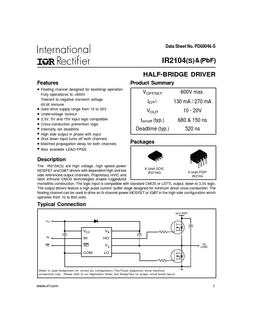
Data Sheet No. PD60046-STypical ConnectionProduct SummaryHALF-BRIDGE DRIVERFeatures•Fully operational to +600VdV/dt immune••Undervoltage lockout•••Internally set deadtime••••Also available LEAD-FREEDescriptionoperates from 10 to 600 volts. 1IR2104(S ) & (PbF)2IR2104(S) & (PbF)Absolute Maximum RatingsAbsolute maximum ratings indicate sustained limits beyond which damage to the device may occur. All voltage parameters are absolute voltages referenced to COM. The thermal resistance and power dissipation ratings are measured under board mounted and still air conditions.Note 1: Logic operational for V S of -5 to +600V. L ogic state held for V S of -5V to -V BS . (Please refer to the Design Tip DT97-3 for more details).Recommended Operating ConditionsThe Input/Output logic timing diagram is shown in Figure 1. For proper operation the device should be used within the recommended conditions. The V S offset rating is tested with all supplies biased at 15V differential.3IR2104(S) & (PbF)Dynamic Electrical CharacteristicsV BIAS (V CC , V BS ) = 15V, C L = 1000 pF and T A = 25°C unless otherwise specified.4IR2104(S) & (PbF)Functional Block DiagramLead DefinitionsSymbol DescriptionINLogic input for high and low side gate driver outputs (HO and LO), in phase with HO Logic input for shutdown V BHigh side floating supply HO High side gate drive output V S High side floating supply return V CC Low side and logic fixed supply LO Low side gate drive output COMLow side returnSDLead Assignments8 Lead PDIP 8 Lead SOICIR2104IR2104S12348765V CC IN SD COMV B HO V S LO12348765V CC IN SD COMV B HO V S LO5IR2104(S) & (PbF) Figure 5. Delay Matching Waveform DefinitionsFigure 4. Deadtime Waveform DefinitionsFigure 3. Shutdown Waveform DefinitionsFigure 1. Input/Output Timing DiagramSDINHO LOFigure 2. Switching Time Waveform Definitions6IR2104(S) & (PbF)7IR2104(S) & (PbF)8IR2104(S) & (PbF)9IR2104(S) & (PbF)10IR2104(S) & (PbF)11IR2104(S) & (PbF)IR2104(S) & (PbF)13IR2104(S) & (PbF)14IR2104(S) & (PbF)LEADFREE PART MARKING INFORMATIONORDER INFORMATIONPer SCOP 200-002Basic Part (Non-Lead Free)8-Lead PDIP IR2104 order IR21048-Lead SOIC IR2104S order IR2104S Leadfree Part8-Lead PDIP IR2104 order IR2104PbF 8-Lead SOIC IR2104S order IR2104SPbFIR WORLD HEADQUARTERS: 233 Kansas St., El Segundo, California 90245 Tel: (310) 252-7105This product has been qualified per industrial levelData and specifications subject to change without notice. 4/2/2004。
IR2104 + IRF540 MOS电机驱动全桥

R2104 + IRF540 MOS电机驱动全桥学习与实践过程/bbs/article_1012_130178.html使用L293或L298等全桥芯片来控制直流电机虽然简便而且成本低廉,但由于它们的内阻较大,在控制大电流的马达时芯片常常过热,导致系统的整体效率较低。
在电动车上,马达控制芯片的内阻过大会导致车子的加速度变小。
本人设想在暑假制作一个大的轮式或者履带式机器人,并且希望它能跑到公交车那么快,于是开始研究如何使用MOS管来控制更大电流的电机。
首先,本人参考了《大功率直流马达的驱动——ABU ROBOCON 2005比赛之动力方案》一文中的电路图(原文地址 /article.php?sid=192 )按照这个原理图,我热转印制作了单个全桥的实验电路。
个别的电阻电容值有所变动。
上电并给予有效的持续高电平信号后发现电路不能驱动马达,而2104开始发烫,540没有任何反应。
于是更换2104,但仍出现同样的现象。
通过示波器检测发现,高端MOS没有被驱动,而低端MOS的G端信号正常,因而桥没有被导通。
更换信号方向,另外半桥仍然出现相同的现象。
本人开始怀疑是BOOTSTRAP电容的问题,于是实验了不同的电容值。
但无论怎么变换,问题仍然没有被解决。
由于手头没有4148,使用了IN5819作为续流二极管,按道理5819只会比4148更好,不应该成为问题的原因。
由于手头2104只有6片,而所有的都上电并且发热过,于是重新购买了一批2104。
在这里感谢周顺同学,那天刚好他毕业考考好,帮我到科技京城买了2104。
更换2104后,电路工作正常。
周顺看了看我原来的2104,恍然大悟:原来的芯片是97年前的旧货。
马达欢快地转了起来。
由于540的内阻要比298小很多,马达的加速度明显提高,变向时电刷更是发出了闪亮的火星。
回到家后用示波器开始研究高端MOS的G端驱动电压波形。
发现在EN端为高的初期,高端MOS的驱动电压突然升至比VCC高10V。
ir2104 半桥驱动器

Data Sheet No. PD60046-STypical ConnectionProduct SummaryHALF-BRIDGE DRIVERFeatures•Fully operational to +600VdV/dt immune••Undervoltage lockout•••Internally set deadtime••••Also available LEAD-FREEDescriptionoperates from 10 to 600 volts. 1IR2104(S ) & (PbF)2IR2104(S) & (PbF)Absolute Maximum RatingsAbsolute maximum ratings indicate sustained limits beyond which damage to the device may occur. All voltage parameters are absolute voltages referenced to COM. The thermal resistance and power dissipation ratings are measured under board mounted and still air conditions.Note 1: Logic operational for V S of -5 to +600V. L ogic state held for V S of -5V to -V BS . (Please refer to the Design Tip DT97-3 for more details).Recommended Operating ConditionsThe Input/Output logic timing diagram is shown in Figure 1. For proper operation the device should be used within the recommended conditions. The V S offset rating is tested with all supplies biased at 15V differential.3IR2104(S) & (PbF)Dynamic Electrical CharacteristicsV BIAS (V CC , V BS ) = 15V, C L = 1000 pF and T A = 25°C unless otherwise specified.4IR2104(S) & (PbF)Lead DefinitionsSymbol DescriptionINLogic input for high and low side gate driver outputs (HO and LO), in phase with HO Logic input for shutdown VB High side floating supply HO High side gate drive output V S High side floating supply return V CC Low side and logic fixed supply LO Low side gate drive output COMLow side returnSDLead Assignments8 Lead PDIP 8 Lead SOICIR2104IR2104S12348765V CC IN SD COMV B HO V S LO12348765V CC IN SD COMV B HO V S LO5IR2104(S) & (PbF)Figure 4. Deadtime Waveform DefinitionsFigure 3. Shutdown Waveform DefinitionsFigure 1. Input/Output Timing DiagramSDINHO LOFigure 2. Switching Time Waveform DefinitionsIR2104(S) & (PbF)67IR2104(S) & (PbF)8IR2104(S) & (PbF)9IR2104(S) & (PbF)10IR2104(S) & (PbF)11IR2104(S) & (PbF)IR2104(S) & (PbF)13IR2104(S) & (PbF)14IR2104(S) & (PbF)Per SCOP 200-002Basic Part (Non-Lead Free)8-Lead PDIP IR2104 order IR21048-Lead SOIC IR2104S order IR2104S Leadfree Part8-Lead PDIP IR2104 order IR2104PbF 8-Lead SOIC IR2104S order IR2104SPbFIR WORLD HEADQUARTERS: 233 Kansas St., El Segundo, California 90245 Tel: (310) 252-7105This product has been qualified per industrial levelData and specifications subject to change without notice. 4/2/2004。
IR2175数据手册中文版

IR2175(S)&(PbF) 线性电流感应IC数据手册 NO. PD60208特点Floating通道最大电压+600V单片集成通过分流电阻进行线性电流反馈直接数字输出、接口简单低IQBS,许诺自举电路供电独立过流爱惜信号高共模抗噪音输入过压爱惜(IGBT短路电流)漏极开路输出无铅制程描述IR2175是专为电机驱动设计的单片电流感应IC 。
它通过外接分流电阻测量电机相电流,把模拟信号转换为数字信号,并把该信号输送到低边。
IR的高压隔离专利技术能够处置高带宽的信号。
输出离散PWM而不需A/D输入接口。
过流信号能够使IGBT短路爱惜。
漏极开路输出适应到15V电压。
模块图产品摘要:Voffset 最大600VIqbs 2mAVin 最大+/-260mV温漂增益 20ppm/℃封装极限额定值超过极限额定值可能发生错误或损坏,所有的电压参数是以COM为参考的绝对数值。
所有电流值概念为正值。
热阻和功耗是在空气静止的环境下在电路板上测得的。
推荐操作条件图一为输出逻辑时序。
设备需工作在推荐操作条件下。
直流电气特性除非特殊概念,VCC=VBS=15V,TA=25℃注释2:Gain=最大占空比/最大输入电压交流电气特性图一输出波形时序提示:同时测量PWM周期和PWM有效时刻能够排除输出载波频率的温漂。
因为他们是同向波动的。
在每一个周期计算它们的比值能够取得排除温漂的测量值。
引脚概念符号描述VCC 低边逻辑供电电压COM 低边逻辑地VIN+ 正感应输入VB 高边电源VS 高边回路PO 数字PWM输出OC 过流输出 (负逻辑). 无连接引脚散布外形尺寸IR2175应用指南AN-10521 大体功能本段说明IR2175的大体操作.该IC把高边的电机驱动电流转换到低边。
模拟输入的电压信号事实上是外接感应电阻的压降。
那个电阻感应电机相电流并产生一个很小的交流电压信号。
最大输入信号为260mV。
因此电阻应选择使电压在260mV之内的值,使过流信号电压达到260mV(如10A过流信号选择26mΩ电阻)。
ir2101中文资料

数据表PD60043典型连接具有浮动通道设计的引导操作完全可操作+600V耐受性负转换电压dV/dt免疫网关驱动电源范围从10个欠压锁定3.3V,5V,15V逻辑输入兼容匹配传播延迟两个通道输入(IR2101)输入(IR2102)描述高压,高速功率MOSFET-igbt 驱动器独立的高低压侧参考输出通道。
专有的HVIC latchimmune CMOS技术支持加固单片结构。
逻辑输入标准CMOS LSTLOUTPUT,下降3.3Vlogic。
输出驱动器具有高脉冲电流缓冲高低压侧驱动程序包产品概要偏置600V最大130mA 270mA输出10开/关(典型)160 150ns延迟匹配50 ns IR2101 IR2102 IR2101 LeadSOIC LeadPDIP阶段设计的最小驱动器交叉传导。
浮动沟道can N沟道功率MOSFET高侧配置,工作电压高达600伏。
网站HOLO-COM-HIN-LIN-HIN-up-HOLO-COM-HIN-LIN-HIN-up-CC(参考引线分配修正引脚配置)。
图表仅显示电气连接。
请参阅我们的应用注意事项电路板布局。
第二章:IR2101/符号定义最小最大单元高压侧浮动电源电压-0.3 625高压侧浮动电源偏移电压HO高压侧浮动输出电压CC低压侧逻辑固定电源电压-0.3 25 L低压侧输出电压-0.3逻辑输入电压(HIN LIN)-0.3 0.3dV/dt允许的偏移电源电压瞬变50V/ns包装功耗导线pdip)导线soic)0.625Rth JA热电阻,连接导线pdip)导线soic)接头温度存储温度-55 150导线温度(焊接,10秒)300绝对最大额定值绝对最大额定值指示持续极限,超过该极限值可能会发生损坏设备。
所有电压参数均为绝对电压参考的热电阻功率耗散额定值,在安装在板上的静止空气条件下测量。
SymbolDefinition 最小最大单位高压侧浮动电源绝对电压高压侧浮动电源偏移电压注HO高压侧浮动输出电压CCLow side logicfixed supply voltage 10 20 Low side output voltage Logicinput voltage (HIN LIN)(IR2101)LIN)(IR2102)环境温度-40 125注释逻辑操作+600V。
ir2110中文资料_数据手册_参数
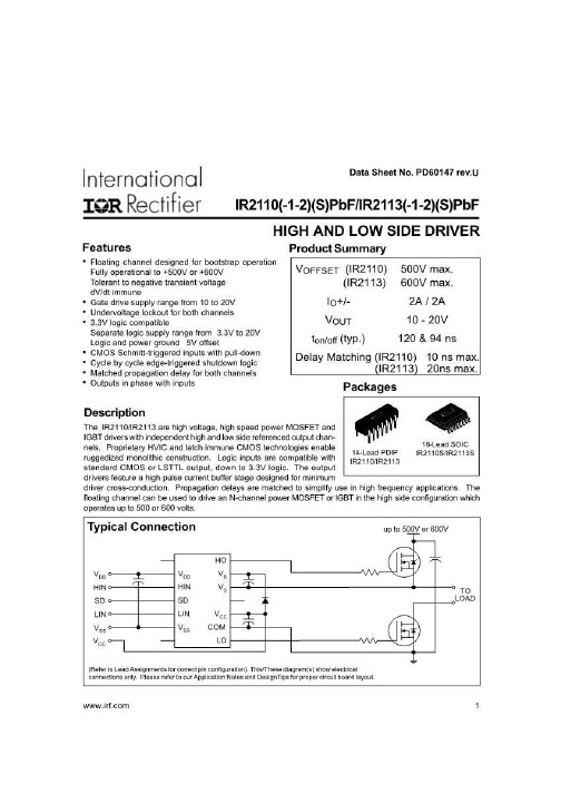
IR2110(-1-2)(S)的PBF / IR2113(-1-2)(S)的PBF功能框图铅定义符号说明 V乙 SD LIN V DD脉冲 GEN [R小号 Q V SS UV 检测延迟 HV水平转移 V CC脉冲过滤 UV检测 V DD / V CC水平转移 V DD / V CC水平转移 LO V小号 COM [R小号 Q [R小号 RQ HIN HO V DD逻辑供应 HIN高端栅极驱动器输出(HO)的逻辑输入,同相 SD逻辑输入关闭 LIN低端栅极驱动器输出(LO) 的逻辑输入,IR2110同相 V SS逻辑地 V B高端浮动供应 HO高端栅极驱动输出 V S高端浮动供应回报 V CC低端供应 LO低端栅极 驱动输出 COM低端回报 关断时间与V CC / V BS 电源电压的关系图9A.关机时间与温度的关系 0 50 100 150 200 250 10 12 14 16 18 20大.典型. 0 50 100 150 200 250 -50 -25 0 25 50 75 100 125温度(°C)大.典型. 0 50 100 150 200 250 02 46 8 10 12 14 16 18 20 VDD电源电压(V)马克斯 .典型 图 9C. 关断时间与V DD IR2110电源电压的关系图10A.上升时间与温度的关系 0 20 40 60 80 100 -50 -25 0 25 50 75 100 125温度(°C) 大.典型.图10B.打开上升时间与电压的关系 0 20 40 60 80 100 10 12 14 16 18 20 V BIAS IR2110电源电压(V)大.典型.图11A.关闭下降 时间与温度的关系 0 10 20三十 40 50 -50 -25 0 25 50 75 100 125温度(°C)大.典型. V CC / V BS 电源电压(V) 图19B. V DD 电源电流与V DD 电压的关系图20A.逻辑“1”输入电流与温度的关系 0 20 40 60 80 100 -50 -25 0 25 50 75 100 125温度 (°C)大.典型. 图17B. V BS 电源电流与电压的关系 0 100 200 300 400 500 10 12 14 16 18 20 V BS 浮动电源电压(V)大.典型. 图 18A. V CC 电源电流与温度的关系 0 125 250 375 500 625 -50 -25 0 25 50 75 100 125温度(°C)大.典型. 图18B. V CC 电源电流与电压 的关系 0 125 250 375 500 625 10 12 14 16 18 20 V CC 固定电源电压(V)大.典型. 图19A. V DD 电源电流与温度的关系 0 20 40 60 80 100 -50 -25 0 25 50 75 100 125温度(°C)大.典型. 0 10 20三十 40 50 60 02468 10 12 14 16 18 20 V DD 逻辑电源电压 PBF功能框图铅定义符号说明 V乙 SD LIN V DD脉冲 GEN [R小号 Q V SS UV检测延迟 HV水平转移 V CC脉冲过滤 UV检测 V DD / V CC水平转移 V DD / V CC水平转移 LO V小号 COM [R小号 Q [R小号 RQ HIN HO V DD逻辑供应 HIN高端栅极驱动器输 出(HO)的逻辑输入,同相 SD逻辑输入关闭 LIN低端栅极驱动器输出(LO)的逻辑输入,同相 V SS逻辑地 V B高端浮动供应 HO高端栅极驱动输出 V S高端浮动供应回报 V CC低端供应 LO低端栅极驱动输出 COM低端回报
IR2010SPBF中文资料
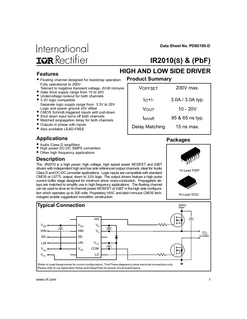
Packages
14-Lead PDIP 16-Lead SOIC
Typical Connection
200V
HO
VDD
VDD
VB
HIN
HIN
VS
SD
SD
LIN
LIN
VCC
VSS
VSS
COM
VCC
LO
(Refer to Lead Assignments for correct configuration). This/These diagram(s) show electrical connections only. Please refer to our Application Notes and DesignTips for proper circuit board layout.
元器件交易网
Data Sheet No. PD60195-D
IR2010(S) & (PbF)
Features
HIGH AND LOW SIDE DRIVER
• Floating channel designed for bootstrap operation Product Summary
Package power dissipation @ TA ≤ +25°C (14 lead DIP) (16 lead SOIC)
Thermal resistance, junction to ambient
(14 lead DIP)
(16 lead SOIC)
Junction temperature
Symbol
VB VS VHO VCC VLO VDD VSS VIN dVs/dt PD
IRS2101STRPBF中文资料
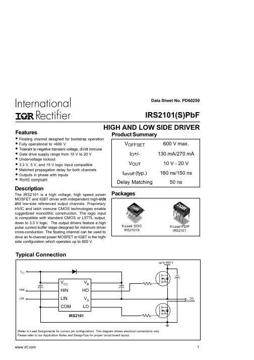
2
元器件交易网
IRS2101(S)PbF
Dynamic Electrical Characteristics
VBIAS (VCC, VBS) = 15 V, CL = 1000 pF and TA = 25 °C unless otherwise specified.
50 1.0 0.625 125 200 150 150 300
Units
V
V/ns W
°C/W °C
Recommended Operating Conditions
The input/output logic timing diagram is shown in Fig. 1. For proper operation the device should be used within the recommended conditions. The VS offset rating is tested with all supplies biased at a 15 V differential.
Package power dissipation @ TA ≤ +25 °C
Thermal resistance, junction to ambient
Junction temperature Storage temperature Lead temperature (soldering, 10 seconds)
V
— 0.05 0.2
IO = 2 mA
— 0.02 0.1
—
—
50
VB = VS = 600 V
—
30 55
— 150 270 µA
VIN = 0 V or 5 V
IRS2110SPBF中文资料

• Fully operational to +500 V or +600 V • Tolerant to negative transient voltage, dV/dt immune • Gate drive supply range from 10 V to 20 V
VOFFSET (IRS2110) (IRS2113)
Symbol
Definition
Min.
Max. Units
VB
High side floating supply voltage
(IRS2110) (IRS2113)
-0.3
520 (Note 1)
-0.3
620 (Note 1)
VS VHO VCC VLO VDD VSS VIN dVs/dt
PD
150
°C
TL
Lead temperature (soldering, 10 seconds)
—
300
Note 1: All supplies are fully tested at 25 V, and an internal 20 V clamp exists for each supply.
Recommended Operating Conditions
Typical Connection
14-Lead PDIP IRS2110 and IRS2113
16-Lead PDIP (w/o leads 4 & 5) IRS2110-2 and IRS2113-2
14-Lead PDIP (w/o lead 4) IRS2110-1 and IRS2113-1
VS + 20 500 600
IR2103SPBF;IR2103PBF;IR2103STRPBF;IR2103;IR2103S;中文规格书,Datasheet资料
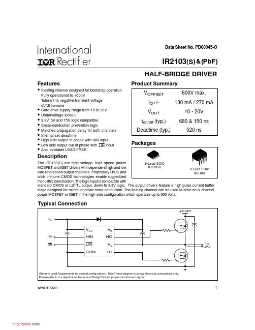
Data Sheet No. PD60045-OTypical ConnectionProduct SummaryHALF-BRIDGE DRIVERFeatures•Fully operational to +600VdV/dt immune••Undervoltage lockout••Cross-conduction prevention logic••Internal set deadtime•••Also available LEAD-FREEDescriptionpower MOSFET or IGBT in the high side configuration which operates up to 600 volts. 1IR2103(S ) & (PbF)IR2103(S) & (PbF)Absolute Maximum RatingsAbsolute maximum ratings indicate sustained limits beyond which damage to the device may occur. All voltage param-eters are absolute voltages referenced to COM. The thermal resistance and power dissipation ratings are measured under board mounted and still air conditions.Note 1: Logic operational for V S of -5 to +600V. Logic state held for V S of -5V to -V BS . (Please refer to the Design Tip DT97-3 for more details).IR2103(S) & (PbF) 3Static Electrical CharacteristicsV BIAS (V CC , V BS ) = 15V and T A = 25°C unless otherwise specified. The V IN , V TH and I IN parameters are referenced to COM. The V O and I O parameters are referenced to COM and are applicable to the respective output leads: HO or LO.Dynamic Electrical CharacteristicsV BIAS (V CC , V BS ) = 15V, C L = 1000 pF and T A = 25°C unless otherwise specified.IR2103(S) & (PbF)4Functional Block DiagramLead DefinitionsSymbol DescriptionHIN Logic input for high side gate driver output (HO), in phase Logic input for low side gate driver output (LO), out of phase VB High side floating supply HO High side gate drive output V S High side floating supply return V CC Low side and logic fixed supply LO Low side gate drive output COMLow side returnLINLead Assignments8 Lead PDIP 8 Lead SOICIR2103IR2103S12348765V CC HIN LIN COMV B HO V S LO12348765V CC HIN LIN COMV B HO V S LOIR2103(S) & (PbF) 5Figure 1. Input/Output Timing DiagramLINHOLOHINFigure 4. Deadtime Waveform DefinitionsFigure 2. Switching Time Waveform DefinitionsLOIR2103(S) & (PbF)6IR2103(S) & (PbF) 7IR2103(S) & (PbF)8IR2103(S) & (PbF)9IR2103(S) & (PbF)10vs Temperaturevs Voltage分销商库存信息:IRIR2103SPBF IR2103PBF IR2103STRPBF IR2103IR2103S IR2103STR。
有关IR2104的自举电容和NMOS选择问题

有关IR2104的自举电容和NMOS选择问题这是我第一次用IR2104有一些疑问希望各位师傅能不吝赐教电机驱动电压为170V,频率40KHZ,电流3A的矩形波电路图如下所示自举电容C3,C4和Q1,Q2,Q3,Q4该如何选择?U1,U2前边是否要加隔离电路?谢谢啦!170v要加光耦了,自举电容1uf低ESL低ESR即可。
是在U1,U2前加的吧恩,前面加~為什麼要加上D3,D4,D5和D6?有何作用?為什麼要加上D3,D4,D5和D6? "dead time management.为mos管放电提供‘低’的回路最好再给mosfet的gs间加个10k的电阻不过有位师傅说限流电阻为33欧姆所以D3,D4,D5,D6加不加无所谓是这样吗?电路图参数已选定,大家帮看看是否合适1N4004和10K其实也可以省~能具体说一下吗?10K电阻不是确保:关机后栅极存储的电荷通过10K电阻迅速释放,以保证电荷的迅速释放的吗?还有1N4004呢?谢谢了!10K不能省,1N4004还是省下来吧,也好几毛钱了NMOS附送的二极管比1N4004高级的多我也认为10K不能省觉得adcr 老稻说的比较又道理都不能省。
10K电阻是用来保护GS在关断时不被击穿,而1N4004是续流用的,不能省,这里建议1N4004换成MUR160以上的快速恢复二极管我还想问下各位师傅自举电容C3,C4应该没有耐压要求吧如果反并联续流管是不是应该注意正向压降问题。
如果你并的压降比体二极管压降大岂不是悲剧了…肖特基或者“同步续流”?请教下GS间10K电阻的作用LZ,我按你的图改改,自己做了块。
上面半桥是正常的,但是下面那半路中MOS管一上电就有1A多的电流输出。
很奇怪,电路没地方短路,2104两端输出均正常。
原理图如下。
自举电容1uf低ESL低ESR即可。
20楼的图,下面的那半桥,为什么HO接到低端MOS,LO接到了高端MOS呢?有没有谁做过用220V ac整流堆整流流出来,然后用ir2104驱动mos管驱动电机的兄弟呢?请问不加光耦有什么后果?0楼歪才,想用一个信号来控制2个2104,(正相和反相),但LO和HO输出电平不一样的,正确做法是一片2104的信号输入端加反相器Nmos不是自己带了一个二极管了吗,为什么还要再加一个续流二极管呢你好,我想问一下为什么1N4004不能省,不是NMOS内部不是已经加了二极管了吗你好,我想问一下为什么1N4004不能省,不是NMOS内部不是已经加了二极管了吗...如果内部有的话可以省掉,自举回路的二极管要用MUR系列的,比较合适如果内部有的话可以省掉,自举回路的二极管要用MUR系列的,比较合适但是我看到有的资料也说MOS内部的二极管是由于寄生作用产生的,性能不是很好。
IR21844SPBF中文资料

HO turn-off to LO turn-on (DTHO-LO) 4
5
Deadtime matching = DTLO - HO - DTHO-LO
—
0
—
0
60
35
520 6 µsec 50 nsec
600
VS = 0V VS = 0V RDT= 0 RDT = 200k RDT=0 RDT = 200k
2
元器件交易网
IR2184(4)(S) & (PbF)
Dynamic Electrical Characteristics
VBIAS (VCC, VBS) = 15V, VSS = COM, CL = 1000 pF, TA = 25°C, DT = VSS unless otherwise specified.
Symbol
Definition
Min.
Max. Units
VB VS VHO VCC VLO DT VIN VSS dVS/dt PD
High side floating absolute voltage High side floating supply offset voltage High side floating output voltage Low side and logic fixed supply voltage Low side output voltage Programmable dead-time pin voltage (IR21844 only) Logic input voltage (IN & SD) Logic ground (IR21844 only) Allowable offset supply voltage transient Package power dissipation @ TA ≤ +25°C (8-lead PDIP)
ir2110中文资料_数据手册_参数

电子元器件采购网-万联芯城 提供中小批量 电子元器件一站式配套采购业务,保证所售产品均为优质原装现 货,万联芯城主打的优势授权代理品牌产品,包括长电科技,顺 络电子,先科 ST 等,价格优势明显。万联芯城已与全国各大终 端工厂企业形成战略合作伙伴关系,欢迎广大采购客户咨询相关 业务。点击进入万联芯城
IR2110(-1-2)(S)的PBF / IR2113(-1-2)(S)的PBF功能框图铅定义符号说明 V乙 SD LIN V DD脉冲 GEN [R小号 Q V SS UV 检测延迟 HV水平转移 V CC脉冲过滤 UV检测 V DD / V CC水平转移 V DD / V CC水平转移 LO V小号 COM [R小号 Q [R小号 RQ HIN HO V DD逻辑供应 HIN高端栅极驱动器输出(HO)的逻辑输入,同相 SD逻辑输入关闭 LIN低端栅极驱动器输出(LO) 的逻辑输入,IR2110同相 V SS逻辑地 V B高端浮动供应 HO高端栅极驱动输出 V S高端浮动供应回报 V CC低端供应 LO低端栅极 驱动输出 COM低端回报 关断时间与V CC / V BS 电源电压的关系图9A.关机时间与温度的关系 0 50 100 150 200 250 10 12 14 16 18 20大.典型. 0 50 100 150 200 250 -50 -25 0 25 50 75 100 125温度(°C)大.典型. 0 50 100 150 200 250 02 46 8 10 12 14 16 18 20 VDD电源电压(V)马克斯 .典型 图 9C. 关断时间与V DD IR2110电源电压的关系图10A.上升时间与温度的关系 0 20 40 60 80 100 -50 -25 0 25 50 75 100 125温度(°C) 大.典型.图10B.打开上升时间与电压的关系 0 20 40 60 80 100 10 12 14 16 18 20 V BIAS IR2110电源电压(V)大.典型.图11A.关闭下降 时间与温度的关系 0 10 20三十 40 50 -50 -25 0 25 50 75 100 125温度(°C)大.典型. V CC / V BS 电源电压(V) 图19B. V DD 电源电流与V DD 电压的关系图20A.逻辑“1”输入电流与温度的关系 0 20 40 60 80 100 -50 -25 0 25 50 75 100 125温度 (°C)大.典型. 图17B. V BS 电源电流与电压的关系 0 100 200 300 400 500 10 12 14 16 18 20 V BS 浮动电源电压(V)大.典型. 图 18A. V CC 电源电流与温度的关系 0 125 250 375 500 625 -50 -25 0 25 50 75 100 125温度(°C)大.典型. 图18B. V CC 电源电流与电压 的关系 0 125 250 375 500 625 10 12 14 16 18 20 V CC 固定电源电压(V)大.典型. 图19A. V DD 电源电流与温度的关系 0 20 40 60 80 100 -50 -25 0 25 50 75 100 125温度(°C)大.典型. 0 10 20三十 40 50 60 02468 10 12 14 16 18 20 V DD 逻辑电源电压 PBF功能框图铅定义符号说明 V乙 SD LIN V DD脉冲 GEN [R小号 Q V SS UV检测延迟 HV水平转移 V CC脉冲过滤 UV检测 V DD / V CC水平转移 V DD / V CC水平转HIN HO V DD逻辑供应 HIN高端栅极驱动器输 出(HO)的逻辑输入,同相 SD逻辑输入关闭 LIN低端栅极驱动器输出(LO)的逻辑输入,同相 V SS逻辑地 V B高端浮动供应 HO高端栅极驱动输出 V S高端浮动供应回报 V CC低端供应 LO低端栅极驱动输出 COM低端回报
这里带你了解IR2104驱动电路

这⾥带你了解IR2104驱动电路Ir2014驱动电路及⾃举电容的应⽤以前做智能车的时候⽤H桥驱动电路,驱动芯⽚就是⽤的,MOS管⽤的IR7843,想把以前的知识总结⼀下。
1、为什么需要H桥电路? 因为驱动电机正反转,我们⽤的是有刷直流电机,如果要电机反转,只需要将电源线和地线调换⼀下顺序即可,调换顺序之后,线圈在磁场中的受⼒⽅向和以前相反,因此电机反转,可以根据初中学的通电导体在磁场中的受⼒⽅向来分析。
可以通过⼀下视频来更详细的了解。
⽽我们需要电机正反转则需要切换电机两端电源的⽅向,因此H桥电路是⼀个很好的选择。
2、IR2104 的的驱动电压是12V,当初电池供电只有8V,所以⽤了MC34063做了升压电路对它供电。
IR2104引脚定义SD信号为使能信号,SD 上⾯有个横杠,代表低电平,也就是说,当SD为低电平的时候,Logic input for shutdown(输⼊被禁⽌)。
因此SD为⾼电平时,芯⽚才可以正常⼯作。
IN为⾼电平时HO为⾼电压(VS+ VB),LO为低(接近于0);IN为低电平时,HO为低,LO为⾼电平。
我们的PWM信号就是在这⾥输⼊,输⼊信号为5V(这个要注意,单⽚机的输出电平最⾼为3.3V,因此采⽤74HC7408D做了电平转换)输⼊逻辑⾼和低:Vb是⾼侧浮动电源输⼊脚,HO是⾼侧门极驱动输出,Vs是⾼侧浮动电源回流。
这三个控制上半桥的MOS导通。
Vcc是电源输⼊脚,LO是低侧门极驱动输出,COM是低侧回流(公共回路)。
这三个控制下半桥的MOS导通。
⾃举电路1.A状态为默认状态,此时开关A闭合,开关B断开,Q1导通,C1负极与地导通,电流从电源V1出发,通过S1,经过C1,经过Q1,再流回电源V1。
达到稳态后,由于⼆极管的PN结0.7V压降,电容上端对地电压为5.3V,下端对地电压为0V。
2.当开关B闭合,开关A断开,Q1截⽌,电容下端电压相对于地来说是电源电压6V。
由于电容两端电压不能突变,电容上端相对电容下端,电压为5.3V,因此电容上端相对于地的电压为5.3V + 6V =11.3V,与电压探针测得值基本⼀致。
ir2101中文资料_数据手册_参数
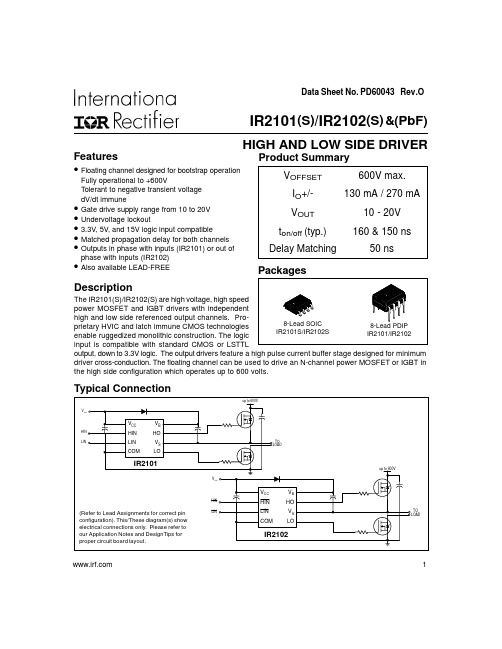
8-Lead SOIC IR2101S/IR2102S
8-Lead PDIP IR2101/IR2102
input is compatible with standard CMOS or LSTTL
output, down to 3.3V logic. The output drivers feature a high pulse current buffer stage designed for minimum
Min.
VS + 10 Note 1
VS 10 0 0 -40
Max.
VS + 20 600 VB 20 VCC VCC 125
Units
V °C
Note 1: Logic operational for VS of -5 to +600V. Logic state held for VS of -5V to -VBS. (Please refer to the Design Tip DT97-3 for more details).
driver cross-conduction. The floating channel can be used to drive an N-channel power MOSFET or IGBT in
the high side configuration which operates up to 600 volts.
IO+/-
130 mA / 270 mA
VOUT
10 - 20V
ton/off (typ.)
160 & 150 ns
Delay Matching
50 ns
phase with inputs (IR2102)
IRS2101PBF中文资料
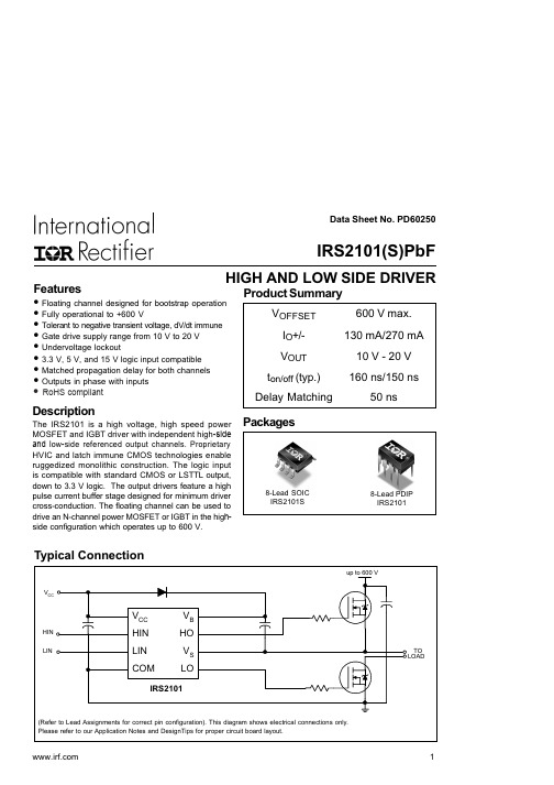
1
元器件交易网
IRS2101(S)PbF
Absolute Maximum Ratings
Absolute maximum ratings indicate sustained limits beyond which damage to the device may occur. All voltage parameters are absolute voltages referenced to COM. The thermal resistance and power dissipation ratings are measured under board mounted and still air conditions.
Symbol
VB VS VHO VCC VLO VIN TA
Definition
High-side floating supply absolute voltage High-side floating supply offset voltage High-side floating output voltage Low-side and logic fixed supply voltage Low-side output voltage Logic input voltage (HIN & LIN) Ambient temperature
Symbol
VB VS VHO VCC VLO VIN dVS/dt
PD
RthJA
TJ TS TL
Definition
High-side floating supply voltage High-side floating supply offset voltage High-side floating output voltage Low-side and logic fixed supply voltage Low-side output voltage Logic input voltage (HIN & LIN) Allowable offset supply voltage transient
IR2101STRPBF中文资料
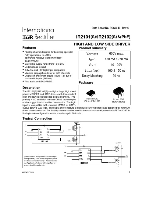
Data Sheet No. PD60043 Rev.OTypical ConnectionFeatures•Fully operational to +600VdV/dt immune••Undervoltage lockout•••phase with inputs (IR2102)•Also available LEAD-FREEHIGH AND LOW SIDE DRIVERProduct SummaryIR2101(S )/IR2102(S ) & (PbF)Description 1IR2101(S )/IR2102(S) & (PbF)Absolute Maximum RatingsAbsolute maximum ratings indicate sustained limits beyond which damage to the device may occur. All voltage param-eters are absolute voltages referenced to COM. The thermal resistance and power dissipation ratings are measured under board mounted and still air conditions.Note 1: Logic operational for V S of -5 to +600V. Logic state held for V S of -5V to -V BS . (Please refer to the Design Tip DT97-3 for more details).Recommended Operating ConditionsThe input/output logic timing diagram is shown in figure 1. For proper operation the device should be used within the recommended conditions. The V S offset rating is tested with all supplies biased at 15V differential.IR2101(S )/IR2102(S) & (PbF) 3Static Electrical CharacteristicsV BIAS (V CC , V BS ) = 15V and T A = 25°C unless otherwise specified. The V IN , V TH and I IN parameters are referenced to COM. The V O and I O parameters are referenced to COM and are applicable to the respective output leads: HO or LO.Dynamic Electrical CharacteristicsV BIAS (V CC , V BS ) = 15V, C L = 1000 pF and T A = 25°C unless otherwise specified.IR2101(S )/IR2102(S) & (PbF)Functional Block DiagramIR2101(S )/IR2102(S) & (PbF)5Lead DefinitionsSymbolDescriptionHIN Logic input for high side gate driver output (HO), in phase (IR2101)HIN Logic input for high side gate driver output (HO), out of phase (IR2102)LINLogic input for low side gate driver output (LO), in phase (IR2101)LIN Logic input for low side gate driver output (LO), out of phase (IR2102)V B High side floating supply HOHigh side gate drive output V S High side floating supply return V CC Low side and logic fixed supply LO Low side gate drive output COMLow side returnLead Assignments8 Lead PDIP 8 Lead SOICIR2101IR2101S8 Lead PDIP 8 Lead SOICIR2102IR2102SIR2101(S )/IR2102(S) & (PbF)Figure 2. Switching Time Waveform DefinitionsFigure 1. Input/Output Timing DiagramHIN LINHO LOHIN LIN Figure 3. Delay Matching Waveform DefinitionsHIN LIN50%50%IR2101(S )/IR2102(S) & (PbF) 7IR2101(S )/IR2102(S) & (PbF)IR2101(S )/IR2102(S) & (PbF)9IR2101(S )/IR2102(S) & (PbF)10IR2101(S )/IR2102(S) & (PbF)IR2101(S )/IR2102(S) & (PbF)Case outlinesIR2101(S )/IR2102(S) & (PbF)IR WORLD HEADQUARTERS: 233 Kansas St., El Segundo, California 90245 Tel: (310) 252-7105This product has been qualified per industrial levelData and specifications subject to change without notice. 4/2/2004LEADFREE PART MARKING INFORMATIONORDER INFORMATIONBasic Part (Non-Lead Free)8-Lead PDIP IR2101 order IR21018-Lead SOIC IR2101S order IR2101S 8-Lead PDIP IR2102 order IR21028-Lead SOIC IR2102S order IR2102SLeadfree Part8-Lead PDIP IR2101 order IR2101PbF 8-Lead SOIC IR2101S order IR2101SPbF 8-Lead PDIP IR2102 order IR2102PbF 8-Lead SOIC IR2102S order IR2102SPbFPer SCOP 200-002。
IR2110PBF中文资料

14-Lead PDIP IR2110/IR2113
16-Lead SOIC IR2110S/IR2113S
drivers feature a high pulse current buffer stage designed for minimum
driver cross-conduction. Propagation delays are matched to simplify use in high frequency applications. The
元器件交易网
Data Sheet No. PD60147 rev.U
IR2110(-1-2)(S)PbF/IR2113(-1-2)(S)PbF
HIGH AND LOW SIDE DRIVER
Features
• Floating channel designed for bootstrap operation
Fully operational to +500V or +600V
Tolerant to negative transient voltage
dV/dt immune
• Gate drive supply range from 10 to 20V • Undervoltage lockout for both channels • 3.3V logic compatible
Separate logic supply range from 3.3V to 20V
Logic and power ground ±5V offset
• CMOS Schmitt-triggered inputs with pull-down • Cycle by cycle edge-triggered shutdown logic • Matched propagation delay for both channels • Outputs in phase with inputs
ir2104中文资料_数据手册_参数

ir2104中文资料_数据手册_参数Data Sheet No. PD60046-STypical ConnectionProduct SummaryHALF-BRIDGE DRIVERFeaturesFully operational to +600VdV/dt immuneUndervoltage lockoutInternally set deadtimeAlso available LEAD-FREE Descriptionoperates from 10 to 600 volts. 1IR2104(S ) & (PbF)2IR2104(S) & (PbF)Absolute Maximum RatingsAbsolute maximum ratings indicate sustained limits beyond which damage to the device may occur. All voltage parameters are absolute voltages referenced to COM. The thermal resistance and power dissipation ratings are measured under board mounted and still air conditions.Note 1: Logic operational for V S of -5 to +600V. L ogic state held for V S of -5V to -V BS . (Please refer to the Design Tip DT97-3 for more details).Recommended Operating ConditionsThe Input/Output logic timing diagram is shown in Figure 1. For proper operation the device should be used within the recommended conditions. The V S offset rating is tested with all supplies biased at 15V differential.3IR2104(S) & (PbF)Dynamic Electrical CharacteristicsV BIAS (V CC , V BS ) = 15V, C L = 1000 pF and T A = 25°C unless otherwise specified.4IR2104(S) & (PbF)Functional Block DiagramLead DefinitionsSymbol DescriptionINLogic input for high and low side gate driver outputs (HO and LO), in phase with HO Logic input for shutdown V BHigh side floating supply HO High side gate drive output V S High side floating supply return V CC Low side and logic fixed supply LO Low side gate drive output COMLow side returnSDLead Assignments8 Lead PDIP 8 Lead SOICIR2104IR2104S12348765V CC IN SD COMV B HO V S LO12348765V CC IN SD COMV B HO V S LO5IR2104(S) & (PbF) Figure 5. Delay Matching Waveform DefinitionsFigure 4. Deadtime Waveform DefinitionsFigure 3. Shutdown Waveform Definitions Figure 1. Input/Output Timing DiagramSDINHO LOFigure 2. Switching Time Waveform Definitions6IR2104(S) & (PbF) 7IR2104(S) & (PbF) 8IR2104(S) & (PbF) 9IR2104(S) & (PbF) 10IR2104(S) & (PbF) 11IR2104(S) & (PbF) IR2104(S) & (PbF)13IR2104(S) & (PbF) 14IR2104(S) & (PbF)LEADFREE PART MARKING INFORMATION ORDER INFORMATIONPer SCOP 200-002Basic Part (Non-Lead Free)8-Lead PDIP IR2104 order IR21048-Lead SOIC IR2104S order IR2104S Leadfree Part8-Lead PDIP IR2104 order IR2104PbF 8-Lead SOIC IR2104S order IR2104SPbFIR WORLD HEADQUARTERS: 233 Kansas St., El Segundo, California 90245 T el: (310) 252-7105This product has been qualified per industrial levelData and specifications subject to change without notice. 4/2/2004万联芯城专注电子元器件配单服务,只售原装现货库存,万联芯城为长电,顺络,先科ST等国内知名原厂的授权代理商,所售电子元器件均为原厂原装正品,只需提交BOM 物料清单,我们将为您报出一个满意的价格,订单最快可当天发出,为客户节省采购时间,提高生产效率,点击进入万联芯城。
ir2104中文资料_数据手册_参数

Symbol
VB VS VHO VCC VLO VIN TA
Definition
High side floating supply absolute voltage High side floating supply offset voltage High side floating output voltage Low side and logic fixed supply voltage Low side output voltage Logic input voltage (IN & SD ) Ambient temperature
Recommended Operating Conditions
The Input/Output logic timing diagram is shown in Figure 1. For proper operation the device should be used within the recommended conditions. The VS offset rating is tested with all supplies biased at 15V differential.
dV/dt immune
• Gate drive supply range from 10 to 20V • Undervoltage lockout • 3.3V, 5V and 15V input logic compatible • Cross-conduction prevention logic • Internally set deadtime • High side output in phase with input • Shut down input turns off both channels • Matched propagation delay for both channels • Also available LEAD-FREE
- 1、下载文档前请自行甄别文档内容的完整性,平台不提供额外的编辑、内容补充、找答案等附加服务。
- 2、"仅部分预览"的文档,不可在线预览部分如存在完整性等问题,可反馈申请退款(可完整预览的文档不适用该条件!)。
- 3、如文档侵犯您的权益,请联系客服反馈,我们会尽快为您处理(人工客服工作时间:9:00-18:30)。
Data Sheet No. PD60046-S
Typical Connection
Product Summary
HALF-BRIDGE DRIVER
Features
•Fully operational to +600V
dV/dt immune
••Undervoltage lockout
•••Internally set deadtime
••••Also available LEAD-FREE
Description
operates from 10 to 600 volts.
1
IR2104(S ) & (PbF)
2
IR2104(S
) & (PbF)
Absolute Maximum Ratings
Absolute maximum ratings indicate sustained limits beyond which damage to the device may occur. All voltage parameters are absolute voltages referenced to COM. The thermal resistance and power dissipation ratings are measured under board mounted and still air conditions.
Note 1: Logic operational for V S of -5 to +600V. L ogic state held for V S of -5V to -V BS . (Please refer to the Design Tip DT97-3 for more details).
Recommended Operating Conditions
The Input/Output logic timing diagram is shown in Figure 1. For proper operation the device should be used within the recommended conditions. The V S offset rating is tested with all supplies biased at 15V differential.
3
IR2104(S
) & (PbF)
Dynamic Electrical Characteristics
V BIAS (V CC , V BS ) = 15V, C L = 1000 pF and T A = 25°C unless otherwise specified.
4
IR2104(S
) & (PbF)
Lead Definitions
Symbol Description
IN
Logic input for high and low side gate driver outputs (HO and LO), in phase with HO Logic input for shutdown V
B High side floating supply HO High side gate drive output V S High side floating supply return V C
C Low side and logic fixed supply LO Low side gate drive output COM
Low side return
SD
Lead Assignments
8 Lead PDIP 8 Lead SOIC
IR2104
IR2104S
1234
8
765
V CC IN SD COM
V B HO V S LO
1234
8
765
V CC IN SD COM
V B HO V S LO
5
IR2104(S
) & (PbF)
Figure 4. Deadtime Waveform Definitions
Figure 3. Shutdown Waveform Definitions
Figure 1. Input/Output Timing Diagram
SD
IN
HO LO
Figure 2. Switching Time Waveform Definitions
IR2104(S
) & (PbF)
6
7
IR2104(S
) & (PbF)
8
IR2104(S
) & (PbF)
9
IR2104(S
) & (PbF)
10
IR2104(S
) & (PbF)
11
IR2104(S
) & (PbF)
IR2104(S) & (PbF)
13
IR2104(S
) & (PbF)
14
IR2104(S
) & (PbF)
Per SCOP 200-002
Basic Part (Non-Lead Free)
8-Lead PDIP IR2104 order IR21048-Lead SOIC IR2104S order IR2104S Leadfree Part
8-Lead PDIP IR2104 order IR2104PbF 8-Lead SOIC IR2104S order IR2104SPbF
IR WORLD HEADQUARTERS: 233 Kansas St., El Segundo, California 90245 Tel: (310) 252-7105
This product has been qualified per industrial level
Data and specifications subject to change without notice. 4/2/2004。
