日控编码器说明书选型资料晓控编码器说明书选型资料NC Series(NEW)
编码器使用说明书
1.※有网友问:增量旋转编码器选型有哪些注意事项?应注意三方面的参数:1.械安装尺寸,包括定位止口,轴径,安装孔位;电缆出线方式;安装空间体积;工作环境防护等级是否满足要求。
2.分辨率,即编码器工作时每圈输出的脉冲数,是否满足设计使用精度要求。
3.电气接口,编码器输出方式常见有推拉输出(F型HTL格式),电压输出(E),集电极开路(C,常见C为NPN型管输出,C2为PNP型管输出),长线驱动器输出。
其输出方式应和其控制系统的接口电路相匹配。
2.※有网友问:请教如何使用增量编码器?1,增量型旋转编码器有分辨率的差异,使用每圈产生的脉冲数来计量,数目从6到5400或更高,脉冲数越多,分辨率越高;这是选型的重要依据之一。
2,增量型编码器通常有三路信号输出(差分有六路信号):A,B和Z,一般采用TTL电平,A脉冲在前,B脉冲在后,A,B脉冲相差90度,每圈发出一个Z脉冲,可作为参考机械零位。
一般利用A超前B或B超前A进行判向,我公司增量型编码器定义为轴端看编码器顺时针旋转为正转,A超前B为90°,反之逆时针旋转为反转B超前A为90°。
也有不相同的,要看产品说明。
3,使用PLC采集数据,可选用高速计数模块;使用工控机采集数据,可选用高速计数板卡;使用单片机采集数据,建议选用带光电耦合器的输入端口。
4,建议B脉冲做顺向(前向)脉冲,A脉冲做逆向(后向)脉冲,Z原点零位脉冲。
5,在电子装置中设立计数栈。
3.※关于户外使用或恶劣环境下使用有网友来email问,他的设备在野外使用,现场环境脏,而且怕撞坏编码器。
我公司有铝合金(特殊要求可做不锈钢材质)密封保护外壳,双重轴承重载型编码器,放在户外不怕脏,钢厂、重型设备里都可以用。
不过如果编码器安装部分有空间,我还是建议在编码器外部再加装一防护壳,以加强对其进行保护,必竟编码器属精密元件,一台编码器和一个防护壳的价值比较还是有一定差距的。
4.※从接近开关、光电开关到旋转编码器:工业控制中的定位,接近开关、光电开关的应用已经相当成熟了,而且很好用。
编码器说明书

目录〈节〉〈页〉1.操作的注意事项 (3)2.编码器的结构和功能 (4)2.1.功能图解 (4)2.2.多旋转型的连接物清单 (5)3.设置程序 (6)4.人工设置 (7)4.1 功能图解 (7)4.1.1 转换器(TA4570N501E110)的外设连接 (7)4.1.2 编码器操作板(TA4561N150E120 ) (8)4.1.3 显示和设置功能 (9)4.2 设置方法 (11)4.2.1 初始程序和操作检测 (11)4.2.2初始设置 (12)4.2.3编码器程序 (15)4.2.4编码器示教 (19)4.2.5状态 (20)4.2.6传输 (21)4.2.7监视 (23)5.功能和执行 (24)5.1编码器(TA4570N501E110) (24)5.2编码器操作板(TA4561N150E120 ) (24)6.输入/输出信号 (28)7.故障检修 (30)7.1 内部故障分离 (30)7.2 编码器和编码器操作板非正常 (30)8.安装程序和感应器的观察 (31)9.链接 (33)9.1 基本链接……………………………………………………… ..339.2 编码器(TA4570N501E110) (33)9.3 PIO输出信号的分配 (37)1.操作的注意事项一般1.仔细阅读说明书和在说明的范围内使用;2.除了顾客由于误操作、不正确安装等引发故障之外,不与保险,在产品交付后起,保修期是一年;3.产品距预计的失效期很长,但是失效率不是零,因此,当产品运行失败,要求产品用户确认所有的故障,对系统采取多种措施,为了避免更严重的系统事故发生;4.产品可能在允许的范围内改变,而事先没有通知。
这些变化会通过“N”,“E”,“V er.No”字符来显示。
存储1.要充分考虑到预防非正常的温度或者湿度,雨水,灰尘,有害气体或水雾。
设计和连接;1.考虑预防任何噪音和内部连接;2.每对感应器的连接用缠绕的屏蔽线缆;3.供应电源为24伏直流电。
编码器使用说明
编码器使用说明光电编码器基础1.1 概述光电编码器是一种集光、机、电为一体的数字化检测装置,它具有分辨率高、精度高、结构简单、体积小、使用可靠、易于维护、性价比高等优点。
近10几年来,发展为一种成熟的多规格、高性能的系列工业化产品,在数控机床、机器人、雷达、光电经纬仪、地面指挥仪、高精度闭环调速系统、伺服系统等诸多领域中得到了广泛的应用。
光电编码器可以定义为:一种通过光电转换,将输至轴上的机械、几何位移量转换成脉冲或数字量的传感器,它主要用于速度或位置(角度)的检测。
典型的光电编码器由码盘(Disk)、检测光栅(Mask)、光电转换电路(包括光源、光敏器件、信号转换电路)、机械部件等组成。
一般来说,根据光电编码器产生脉冲的方式不同,可以分为增量式、绝对式以及复合式三大类。
按编码器运动部件的运动方式来分,可以分为旋转式和直线式两种。
由于直线式运动可以借助机械连接转变为旋转式运动,反之亦然。
因此,只有在那些结构形式和运动方式都有利于使用直线式光电编码器的场合才予使用。
旋转式光电编码器容易做成全封闭型式,易于实现小型化,传感长度较长,具有较长的环境适用能力,因而在实际工业生产中得到广泛的应用,在本书中主要针对旋转式光电编码器,如不特别说明,所提到的光电编码器则指旋转式光电编码器。
1.2 增量式光电编码器1.2.1 原理及其结构增量式光电编码器的特点是每产生一个输出脉冲信号就对应于一个增量位移,但是不能通过输出脉冲区别出在哪个位置上的增量。
它能够产生与位移增量等值的脉冲信号,其作用是提供一种对连续位移量离散化或增量化以及位移变化(速度)的传感方法,它是相对于某个基准点的相对位置增量,不能够直接检测出轴的绝对位置信息。
一般来说,增量式光电编码器输出A、B两相互差电度角的脉冲信号(即所谓的两组正交输出信号),从而可方便地判断出旋转方向。
同时还有用作参考零位的Z相标志(指示)脉冲信号,码盘每旋转一周,只发出一个标志信号。
编码器快速使用说明
编码器快速使用说明编码器是一种用于将信息从一种形式转换为另一种形式的设备或程序。
它通常用于将人类可读的信息转换为计算机可处理的格式,或者将计算机生成的数据转换为人类可读的格式。
编码器在计算机科学、通信、媒体等领域都有广泛的应用。
在本篇文章中,我们将介绍一种常见的编码器类型和他们的应用领域,以及一些常见的编码器使用实例。
1.ASCII编码器:ASCII编码器是最常见的编码器之一,它将字符转换为相应的ASCII 码。
例如,字符'A'将被编码为65,字符'Z'将被编码为90。
ASCII编码器通常用于计算机编程、通信协议等领域。
使用方法:要使用ASCII编码器,只需将字符作为输入传递给编码器函数,然后获取返回的ASCII码。
例如,在Python中,可以使用ord(函数获取字符的ASCII码:```pythonchar = 'A'ascii_code = ord(char)print(f"The ASCII code of {char} is {ascii_code}")```输出结果为:“The ASCII code of A is 65”。
2.URL编码器:URL编码器用于将URL中的特殊字符转换为安全可传输的格式。
例如,空格字符在URL中需要被转换为%20,而其他特殊字符也需要进行类似的转换。
URL编码器主要用于Web开发和网络通信中。
使用方法:对于URL编码器,在大多数编程语言中都有相应的函数或库可用。
例如,在Python中,可以使用urllib库的quote(函数进行URL编码:```pythonimport urllib.parseencoded_url = urllib.parse.quote(url)print(f"The encoded URL is: {encoded_url}")```3. Base64编码器:Base64编码器用于将二进制数据转换为可打印的ASCII字符。
进口编码器欧姆龙光洋品牌内密控等
TRD-2T2500AF
TRD-2T2500BF
TRD-2T2500V
TRD-2T300BF
TRD-2T360BF
TRD-2T360BF-2M
TRD-2T360V
TRD-2T400BF
TRD-2T400V
TRD-2T500B
TRD-2T500BE
TRD-2TH250BF
TRD-2TH360AF
TRD-2TH360BF
TRD-2TH360BF-2M
TRD-2TH500AF
TRD-2TH500V
TRD-2TH600BF
TRD-2TH60B
TRD-2TH60V
TRD-GK10-R
TRD-GK100-BZ
TRD-J400-SW
TRD-J500-RZ
TRD-J500-RZC
TRD-J500-RZL
TRD-J500-RZV
TRD-J500-RZW
TRD-J50-RZ
TRD-J50-RZW
TRD-J600-RZ
TRD-J600-RZC
TRD-J10-SW
TRD-J200-RZ
TRD-NA2048NW
TRD-NA256NW
TRD-NA256NW5M
TRD-NA256PW
TRD-NA256PW5M
TRD-NA360NW
TRD-NA360NW5M
TRD-NA360NWF5M
TRD-NA360PW
TRD-NA360PW5M
TRD-NA720NWF5M
TRD-K1024-YC2
TRD-K1024-YS
日鼎DHE-SF系列省线式编码器伺服简易说明书
简易操作说明书安全警告安全事项.操作、运转时的注意事项目录第一章概述1.1伺服驱动器型号说明 (1)1.2伺服电机型号说明 (1)第二章驱动器及电机安装2.1伺服驱动器安装尺寸 (2)2.2供电电源 (3)2.3接线图 (3)第三章配线及详细说明3.1指令控制序列输入输出接口(CN1) (4)3.2编码器接口(CN2) (5)3.3通讯接口(CN3) (5)第四章伺服参数说明4.1参数设置 (6)4.2参数一览表 (6)第五章伺服主要操作功能5.1触摸面板介绍 (10)5.2参数设置 (10)5.3功能一览 (11)第六章伺服报警6.1报警内容 (12)6.2报警解释及报警处理方法 (12)附件一伺服电机和驱动器匹配表 (16)附件二电机代码设置方法 (17)附件三制动电阻的选择 (17)第一章概述1.1伺服驱动器型号说明DHE3205-S F*1234561:表示控制器类型为:DHE系列;2:表示电源电压等级,32代表三相或单相交流220V;3:表示额定输出电流,单位为安培(A);4:表示对应电机编码器类型,S:省线式编码器5:F代表通用;6:不同字母代表控制器不同的特殊功能。
1.2伺服电机型号说明130ST-Z S050C2A-I/**123456789101:表示机座号,目前共有八种尺寸的机座:40、60、80、90、110、130、150、180(单位为mm)。
2:表示性能参数代号,“ST”代表正弦波驱动的永磁同步交流伺服电机。
3:“Z”表示带电磁式抱闸制动器;“Y”表示带永磁式抱闸制动器;缺省表示不带抱闸制动器。
4、表示电机的反馈类型,“S”代表2500ppr省线式光电编码器;5、表示额定输出力矩,单位:×0.1N.m;6、表示电机的额定转速:A代表1500r/min D代表3000r/minB代表2000r/min E代表1000r/minC代表2500r/min7、表示电机的工作电压,“2”代表3相AC220V;“4”代表3相AC380V;8、输出轴形式:A代表直轴,带键,键宽6mm E代表直轴带键,键宽10mmB代表直轴无键F代表直轴带键,键宽4mmC代表直轴带键,键宽8mm G代表直轴带键,键宽12mmD代表直轴带键,键宽5mm H代表直轴带键,键宽3mm9、派生号,表示电机编码器的规格;10、派生号,区分细节差别,非标配电机时用。
PLUTO安全PLC手册:绝对编码器说明书
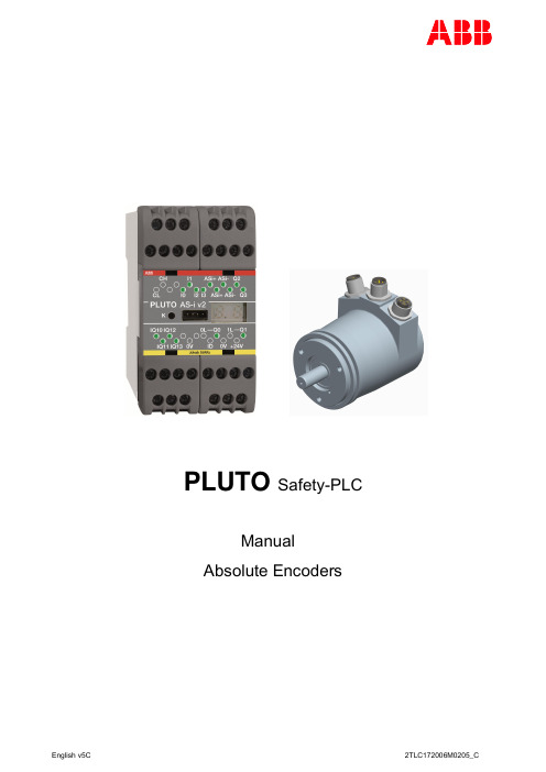
PLUTO Safety-PLCManualAbsolute EncodersTable of contents:1General (3)1.1Reaction time (3)1.2Safety parameters (3)2Electrical (4)2.1Separation with Gateway in Bridge Mode (5)2.2CAN bus data (5)3Singleturn encoder RSA 597/RHA 597 (6)3.1Address setting (6)3.2Software settings (7)3.2.1Baudrate (7)3.2.2Scale (7)3.2.3Position adjustment (8)3.3Speed limit (9)3.4Technical data (9)3.4.1Electrical data (9)3.4.2Mechanical data (10)4Multiturn encoder RSA 698/RHA 698 (13)4.1Connectors (13)4.2Indicators (13)4.3Address setting (14)4.4Baudrate (14)4.5Software settings (14)4.5.1Scaling (15)4.5.2Position adjustment (15)4.6Technical data (16)4.6.1Electrical data (16)4.6.2Mechanical data (17)5PLC Software - Description of function blocks (20)5.1SafeEncoder (20)5.2SafeEncoderMult (21)5.2.1SafeEncoderMult32 (22)5.3EncoderCam (23)5.3.1EncoderCam32 (23)Pluto can handle up to 16 absolute encoders connected to the CAN bus. However, the encoders themselves can only be addressed to one of 8 different addresses (for Multiturn encoders 9 addresses, but a safe solution requires that the encoders are mounted in pairs). This leads to that in practice a maximum of 8 encoders can be used.One of the Pluto units on the bus must have software option for communication with the encoders. This special Pluto sends cyclically a sync telegram, which trigs all encoders on the bus to read the position and send a telegram with the position value back to the bus. The special Pluto can read the encoder telegrams and evaluate them. With block functions in the PLC code it is then possible to make a dual channel function with two encoders. Out of this the user gets failsafe values for position and speed including stand still monitoring and over speed detection.The encoders are standard absolute encoders with modified software to meet the safety requirements.1.1 Reaction timeThe encoders are read every 10 ms. The system tolerates that a single reading of an encoder fails, but if two or more fails, it leads to failure alarm. This leads to the response times as below. Response time:Normal conditions: 11 ms + program execution time 14 msBy fault: 31 ms + program execution time 34 ms1.2 Safety parametersA system with two encoders connected to a Pluto with a PLC program which uses the block functions described in this manual (see 5) meets the safety levels below.The values are the same as for the use of other input types, such as normal digital I/O:s or AS-i bus sensors. The values are including the encoders.SIL according to IEC 61508, EN 62061 SIL 3Charge pump outputs* (Q2, Q3)PFD AV (for proof test interval = 20 years) 1.5 x 10⁻⁴PFH D according to IEC 61508, EN 62061 1.5 x 10⁻⁹Relay outputs* (Q0, Q1, Q4, Q5)PFD AV (for proof test interval = 20 years) 1.5 x 10⁻⁴PFH D according to IEC 61508, EN 62061 2.0 x 10⁻⁹PL according to EN ISO 13849-1 PL eCategory according to EN ISO 13849-1 4MTTF d according to EN ISO 13849-1 High/1500 yearsDC avg according to EN ISO 13849-1 High*Encoder to output.For more details see Pluto hardware manual.2.1 Separation with Gateway in Bridge ModeBy using a Gateway GATE-C2 or GATE-D2 in bridge mode it is possible to separate the Encoders so that different Pluto units communicate with different Encoders. The Gateway will filter out the Encoder telegrams, but let the other telegrams pass through. (See 8.1 “Pluto filter” in thePluto_Gateway_Manual.)2.2 CAN bus dataEach encoder gives bus load equivalent to two Pluto units. This leads to that with a certain CAN speed, the maximum amount of Pluto units will be reduced by two for each encoder. For example a Pluto-bus running with 250 kbit/s and 4 encoders can have 14-24 Pluto units instead of 22-32. For bus data as cable length / baudrate, amount of bus nodes, etc., see Pluto - Operating instructions - Hardware.In this example Pluto 1 communicates with Encoder 1 and 2, while Pluto 3 communicates with Encoder 3 and 4.3 Singleturn encoder RSA 597/RHA 597The singleturn encoder comes in four variants:RSA 597 with 12-pin connector.RSA 597 with 1.5 meter cable.RHA 597 with hollow shaft and 2 meter cable.RHA 597 with hollow shaft and 10 meter cable.Besides connection of power supply and CAN bus the connector/cable is also used for setting the address with jumpers (see Address settings below).3.1 Address settingThe encoder must be addressed 1-8 by connecting pin 1…4 with pin 11 in the connector/cable. By exchange of encoder the addressing will automatically be made by fitting the connector.1 = Not connected0 = Connected to pin 11.Example: Encoder address 3 – Pin 3 connected to Pin 11 and Pin 1, 2, 4 not connected.3.2 Software settingsAn encoder can be adjusted from Pluto by using Terminal Window in Pluto Manager.By connection the prompt Pluto_A> shall be visible.Type “encoder” for entering the encoder menu where it is possible to change baudrate (B), set the current position (A) and rescale the encoder (I).NOTE: If an encoder with wrong baud rate is connected to a running Pluto buss the CAN-bus communication fails.3.2.1 BaudrateBaudrate: 125, 250, 500, 800 kbit/s or 1 Mbit/s. (Default Pluto setting 400kbit/s is not possible.) At delivery the encoders are set to 500 kbps. Note that the encoder must be powered off/on before the new setting is valid.3.2.2 ScaleExample of setting the scale to degrees.Addr.Pin 4 Parity Pin 3 Bit 2 Pin 2 Bit 1 Pin 1Bit 0 1 0 0 0 1 2 0 0 1 0 3 1 0 1 1 4 0 1 0 0 5 1 1 0 1 6 1 1 1 0 7 0 1 1 1 8 1 0 0 03.2.3 Position adjustment The current position is setto 90.3.3 Speed limitBy use of single turn encoder for speed monitoring the maximum allowed rotating speed is limited to 50 rev/s = 3000 rpm. If the speed is exceeded the speed value will be negative.Note: It must be secured by limitations in application that the maximum speed is not exceeded or that no dangerous situations can occur if it does.Examples of such limitations are: An induction motor which speed is limited by the frequency or a hydraulic cylinder which is limited by a maximum pump capacity.3.4 Technical dataType designation Variant Interface Article number, ABBRSA 597 With 12-pole connector CAN04 2TLA020070R3600RSA 597 With 1.5 m. cable CAN04 2TLA020070R3300RHA 597 Hollow shaft, with 2 m. cable CAN04 2TLA020070R3400RHA 597 Hollow shaft, with 10 m. cable CAN04 2TLA020070R5900Encoder dataType RSA 597, RHA 597Operating temperature -40°C .. +70°CStorage temperature -30°C .. +70°CIngress protection class IP-67 according to IEC 60529At shaft inlet IP-66 according to IEC 60529Vibration (55 to 2000Hz) < 300 m/s2 according to IEC 60068-2-6Shock (6ms) < 2000 m/s2 according to IEC 60068-2-27Cover material AluminiumCover surface treatment Coated and cromated or anodizedWeight Approx. 300gAccuracy and resolutionResolution 13 Bit, 8192 positions per revolutionAccuracy ± ½ LSB3.4.1 Electrical dataDefault baud rate is 500kbit/s.Power supply 9-36 VdcPolarity protected YesOutput interface CANPlutoShort circuit protected YesInterface CAN specifications 2.0 part A and BApplication layer Safe EncoderBaud rate 5 kbit/s - 1 Mbit/sCAN identifier 3 bit hardware adjustableAddress input Active lowCode type BinaryProgrammable functions Resolution, PresetDirection, Baud rateNode IDCurrent consumption 50mA @ 24VdcMax current consumption 100mA3.4.2 Mechanical dataRSA 597 with 12-pin connectorShaft specification Flange specificationShaft type Ø 10 with face Flange type 63, Synchro Axial shaft load 50 N Outer diameter ø58 mm Radial shaft load 60 N Mounting holes 3 x M4 Mech. permissible speed 6000 rpm (12 000) Flange material Aluminium Shaft material Stainless steel Surface treatment Anodized Moment of inertia 2,0 x 10⁻⁶ kgm2RSA 597 with cableShaft specification Flange specificationShaft type Ø 6 with face Flange type 63, Synchro Axial shaft load 50 N Outer diameter ø58 mm Radial shaft load 60 N Mounting holes 3 x M4 Mech. permissible speed 6000 rpm (12 000) Flange material Aluminium Shaft material Stainless steel Surface treatment Anodized Moment of inertia 1,9 x 10⁻⁶ kgm2RHA 597 hollow shaft with cableShaft specification Flange specificationHollow shaft type Ø 12 hs Flange type 56, hollow shaft Axial shaft load 10 N Diameter ø58 mmRadial shaft load 20 N Flange material Aluminium Mech. permissible speed 6000 rpm Surface treatment AnodizedShaft material Stainless steel Torque support Torque arm Moment of inertia 2,0 x 10⁻⁶ kgm24 Multiturn encoder RSA 698/RHA 6984.1 Connectors4.2 IndicatorsSTATUS : Follows the CANopen standard.GreenOK Flashing red/greenFault Example:Wrong baudrate Baudrate conflict Flashing green/short redNo contact with busMODULE: Indicates sensor status.GreenOK Flashing redFault Example:Address switches set to different values Baudrate switch set to 9. Sensor faultCAN BusPin CAN Shield 1 CAN V+ 2 CAN GND 3 CAN High 4 CAN Low5Power supply 24 VDC Pin +24 Volt 1 -2 0 Volt3 -4Switches under the cover.Address switches must be set to same value.Connectors and indicators4.3 Address settingThe address is set by the two rotaryswitches under the cover. The two address switches shall be set to the same value.Note : The encoder must be powered off/on before the new setting is valid.4.4 BaudrateThe baudrate is set by the switch under the cover.Note : The encoder must be powered off/on before the new setting is valid.4.5 Software settingsVia Terminal window in Pluto Manager it is possible to scale, set actual position and get information.- Connect the computer to Pluto and start Pluto Manager. Start the terminal window. - Start by typing encoder and v and s to see if the encoders are present on the bus:In this case encoder 5 and 6 are present on the bus.The “v” command (version) shows serial number, version of hardware and software and operating time.The status command “s” gives scaled and hardware resolution, position. Here the encoders are configured to emulate singleturn encoders (scaled res turns=1) with 4000 increments/rev. The encoders must be scaled so that the total range is with 0 to 31999.AddressSwitch 1, 21 1, 12 2, 23 3, 34 4, 45 5, 56 6, 67 7, 78 8, 8 99, 9Baud rate Baudrate switch10 Kbit 0 20 Kbit 1 50 Kbit 2 125 Kbit 3 250 Kbit 4 500 Kbit 5 800 Kbit 6 1000 Kbit 7 400 Kbit 8 Error94.5.1 ScalingThe encoder is rescaled by the command “i”.In below example the encoder is set to 100 increments/rev in multiturn mode. This means we can have up to 320 turns within the total range. Rotation direction is clockwise:By typing “s” after the rescaling we can see that the total range is 409600, but since Pluto only has 16-bit arithmetic only the part between 0 and 31999 is usable.4.5.2 Position adjustmentIn below example the actual encoder position is adjusted to 5000.By typing “s” after the rescaling we can see that the position is changed to 5000.If the encoder is turned and “s” is typed again we can see that the position is changed.It is also possible to type “p” (position) to get the actual position. If position is displayed by the status command but not for the “p” command, probably the position is outside range 0-31999.Type designation Variant Interface Article number, ABB RSA 698 Multiturn CAN042TLA020070R3700 RSA 698 Multiturn, 6mm shaft CAN042TLA020071R7800 RHA 698 Multiturn, Hollow shaft CAN042TLA020071R7900 Encoder dataType RSA 698, RHA 698Operating temperature -40°C .. +70°CStorage temperature -30°C .. +70°CIngress protection class IP-67 according to IEC 60529At shaft inlet IP-66 according to IEC 60529Vibration (55 to 2000Hz) < 100 m/s2 according to IEC 60068-2-6Shock (6ms) < 2000 m/s2 according to IEC 60068-2-27Cover material AluminiumCover surface treatment AnodizedWeight Approx. 400gAccuracy and resolutionTotal Resolution 25 BitSingle turn resolution 13 Bit, 8192 positions per revolutionMultiturn resolution 12 Bit, 4096 absolute number of revolutions Accuracy ± ½ LSB4.6.1 Electrical dataPower supply 9-36 VdcPolarity protected YesOutput interface CANPlutoNode address Settable via DIP SwitchBaud rate Settable via switch, Max 1MBit/sDefault Baud rate 125 kBit/sCode type BinaryProgrammable functions Scaling, PresetCode sequenceCurrent consumption 90 mA @ 24VdcMax current consumption 150 mA @ 24VdcRSA 698 MultiturnShaft specification Flange specificationShaft type Ø 10 round Flange type 63, Synchro Axial shaft load 50 N Outer diameter ø58 mm Radial shaft load 60 N Mounting holes 3 x M4 Mech. permissible speed 12000 rpm Flange material Aluminium Shaft material Stainless steelMoment of inertia 2,0 x 10⁻⁶ kgm2Shaft specificationFlange specificationShaft type Ø 6 round Flange type 63, Synchro Axial shaft load 50 N Outer diameter ø58 mm Radial shaft load 60 N Mounting holes 3 x M4 Mech. permissible speed 12000 rpm Flange material Aluminium Shaft material Stainless steelMoment of inertia 1,9 x 10⁻⁶ kgm 2Shaft specification Flange specificationShaft type Ø 12 hs Flange type 58, HSAxial shaft load 10 N Outer diameter ø58 mm Radial shaft load 20 N Torque support Stator coupling Mech. permissible speed 6000 rpm Flange material Aluminium Shaft material Stainless steelMoment of inertia 4,3 x 10⁻⁶ kgm25 PLC Software - Description of function blocksThe safety blocks for reading encoders are located in file “encoder01.fps”.5.1 SafeEncoderFunction block for singleturn encoders generating safe position and speed value out of two absolute encoders.------------ Function ------------------------------The function block reads and evaluates two absolute encoders. Theaverage of the two encoders is calculated and set to the output “Position”.The output ”Speed” is also an average value given in increments/10ms.It is also monitored that the two encoder values do not deviate more thanthe value set by the input “MaxDiff”.If something is wrong the output “OK” is set “0”'. In some applicationthe values “Position” and 'Speed' must be used together with the “OK”output.---------- Description of in- and outputs ------------------- AdrEncoderA: Encoder A node address- AdrEncoderB: Encoder B node address- MaxDiff: Max allowed deviation between the encoders (max 2% ofRange)- Range: Number of increments per revolution- OK: Set when encoders are working OK andthe position values are within the margin set by “MaxDiff”- Position: Position value- Speed: Speed value as increments/10ms- A: Encoder A position. Must not be used in PLC program!- B: Encoder B position. Must not be used in PLC program!NOTE! Position values from single encoders are only availablefor adjustment purposes and must NOT be used for safety.NOTE! When error occurs “Position” = -1, “Speed” = -32768 and the OK output will be reset.Function block for multiturn encoders generating safe position and speed value out of two absolute encoders.------------ Function ------------------------------The function block reads and evaluates two absolute multiturnencoders. The average of the two encoders is calculated and set to theoutput “Position”.The output “Speed” is also an average value given inincrements/10ms.It is also monitored so the two encoder values do not deviate morethan the value set by the input “MaxDiff”.If something is wrong the output “OK” is set “0”. In some applicationthe values “Position” and “Speed” must be used together with the “OK”output.---------- Description of in- and outputs ------------------- AdrEncoderA: Encoder A node address- AdrEncoderB: Encoder B node address- MaxDiff: Max allowed deviation between the encoders(max 2% of IncrPerRev)- IncrPerRev: Number of increments per revolution- OK: Set when encoders are working OK andthe position values are within the margin set by “MaxDiff”- Position: Position value- Speed: Speed value as increments/10ms- A: Encoder A position. Must not be used in PLC program!- B: Encoder B position. Must not be used in PLC program!NOTE! Position values from single encoders are only availablefor adjustment purposes and must NOT be used for safety.NOTE! When error occurs “Position” = -1, “Speed” = -32768 andthe OK output will be reset.Same as SafeEncoderMult but for Pluto with “Instruction set 3” (see Pluto Programming Manual). Can handle double registers.The function block reads and evaluates two absolute multiturnencoders. The average of the two encoders is calculated and set to theoutput “Position”.The output “Speed” is also an average value given in increments/10ms.It is also monitored so the two encoder values do not deviate more thanthe value set by the input “MaxDiff”.If something is wrong the output “OK” is set “0”. In some applicationthe values “Position” and “Speed” must be used together with the “OK”output.---------- Description of in- and outputs ------------------- AdrEncoderA: Encoder A node address- AdrEncoderB: Encoder B node address- MaxDiff: Max allowed deviation between the encoders(max 2% of IncrPerRev)- IncrPerRev: Number of increments per revolution- Range: This value should be set to the total number of increments(IncrPerRev * number of turns). *See example below.- OK: Set when encoders are working OK andthe position values are within the margin set by “MaxDiff”- Position: Position value- Speed: Speed value as increments/10ms- A: Encoder A position. Must not be used in PLC program!- B: Encoder B position. Must not be used in PLC program!*Example: An encoder has a resolution of 1000 increments per revolution (IncrPerRev) and 4096 turns. In this case “Range” should be set to 4096000 and “IncrPerRev” to 1000. In terminal windowthis can be seen by typing “encoder”, followed by “s”.NOTE! Position values from single encoders are only available for adjustment purposes and must NOT be used for safety.NOTE! When error occurs “Position” = -1, “Speed” = -2147483648 and the OK output will be reset.5.3 EncoderCamFunction block for electronic cam limit switch.------------ Function ------------------------------The output Q is set when the value in the input register PosRegis within the limits MinPos and MaxPos. The input value is normallyGenerated by the function block SafeEncoder.NOTE! It is possible to specify a cam which passes throughthe zero position of an encoder. Position<0 is forbidden.Example: If MinPos=3000 and MaxPos=200, Q is setwhen the position is greater than 2999 or less than 201.---------- Description of in- and outputs ------------------- PosReg: Register where the position is stored- MinPos: Min allowed value- MaxPos: Max allowed value5.3.1 EncoderCam32Same as SafeEncoderMult but for “Instruction set 3” (see Pluto Programming Manual). Can handle double registers.------------ Function ------------------------------The output Q is set when the value in the input register PosRegis within the limits MinPos and MaxPos. The input value is normallyGenerated by the function block SafeEncoder.NOTE! It is possible to specify a cam which passes throughthe zero position of an encoder. Position<0 is forbidden.Example: If MinPos=3000 and MaxPos=200, Q is setwhen the position is greater than 2999 or less than 201.---------- Description of in- and outputs ------------------- PosReg: Register where the position is stored- MinPos: Min allowed value- MaxPos: Max allowed value。
日进伺服驱动器资料(手册)

日进伺服驱动器资料(手册)
日进伺服驱动器是一种智能驱动器,能够实现精确的位置和速度控制。
以下是关于日进伺服驱动器的基本资料:
1. 产品特点:日进伺服驱动器具有高精度、高响应、高可靠性和高性能的特点。
它通过准确的电流控制,实现驱动电机的位置和速度控制,可以满足各种精密运动控制的需求。
2. 产品型号:日进伺服驱动器有多个型号可供选择,根据需要可以选择不同功率和控制精度的驱动器。
3. 功能特点:日进伺服驱动器具有多种功能特点,包括位置模式、速度模式、力矩控制模式等。
4. 输入输出接口:日进伺服驱动器通常具有多个输入输出接口,可以与外部设备(如编码器、传感器等)进行连接,实现更多功能的扩展和控制。
5. 手动调节功能:日进伺服驱动器一般具有手动调节功能,可以通过手动编码器或按钮进行调节和操作。
6. 保护功能:日进伺服驱动器具有多种保护功能,包括过流保护、过热保护、过载保护等,保证设备的安全和可靠运行。
关于日进伺服驱动器的详细资料,可以参考相关的产品手册或官方网站,其中包含了更多的技术参数、安装指南、操作说明和应用示例等内容。
日进伺服驱动器资料(手册)
日进伺服驱动器资料(手册)摘要:一、日进伺服驱动器概述1.日进伺服驱动器的定义2.日进伺服驱动器的作用3.日进伺服驱动器的应用领域二、日进伺服驱动器的工作原理1.伺服系统的组成2.工作原理简述3.控制方式介绍三、日进伺服驱动器的性能特点1.精确控制2.快速响应3.高效率4.高可靠性四、日进伺服驱动器的分类与选型1.分类2.选型要点五、日进伺服驱动器的使用与维护1.使用注意事项2.日常维护3.故障排除六、日进伺服驱动器在我国的发展与应用1.发展历程2.市场规模3.行业应用正文:日进伺服驱动器是一种将接收的电信号转换为精密、快速、高效的转矩或速度输出的驱动装置,广泛应用于工业自动化、机器人、数控机床、航空航天、医疗设备等领域。
日进伺服驱动器的工作原理主要是通过将输入的电信号与设定的目标值进行比较,然后根据误差信号产生相应的控制作用,以实现对运动部件的精确控制。
其核心部分是伺服控制器,它可以根据指令信号和反馈信号,自动调整电机的工作状态,从而确保电机能够精确、快速地响应外部需求。
日进伺服驱动器具有许多卓越的性能特点,如精确控制、快速响应、高效率和可靠性高等。
这些特点使得日进伺服驱动器在各种应用场景中都能发挥出良好的性能。
在选购日进伺服驱动器时,需要根据实际需求进行分类选择,主要分为速度控制型、转矩控制型和位置控制型。
此外,在选型过程中还需要考虑诸如额定功率、额定转矩、额定速度、惯量匹配等因素。
正确使用和维护日进伺服驱动器对于保证设备的稳定运行至关重要。
在使用过程中,要注意避免过载、过热、电压波动等不利因素。
日常维护主要包括清洁、检查和润滑等。
当出现故障时,可以通过故障诊断和排除方法来解决问题。
日进伺服驱动器在我国经过多年的发展,市场规模逐渐扩大,产品种类日益丰富,技术水平不断提高,已经广泛应用于各个行业。
Omron EC21 电子编码器说明书

NEWNEWIncrementalEncodersMetalShaftInsulated ShaftRing TypeHollowShaftSoldering surfacetemperatureSoldering temperatureHeating timeSoldering timeNo. of soldersEC10E, EC12D, EC12E, EM11B EC45A EC40A EM20BEC09E, EC11B, EC111, EC11E, EC11G,EC11K, EC18A, EC21A, EC28A, EC35A, EC35AH, EC35B, EC50A, EC60B Series100℃ max.260±5℃2 min. max.5±1s2 time max.100℃ max.100℃ max.110℃ max.80℃ max.260±5℃260℃ max.260℃ max.260℃ max.1 min. max.2 min. max.1 min. max.1 min. max.3±1s 5s max.10s max.3s max.2 time max.2 time max.1 time 2 time max.PreheatingDip solderingReference for Dip SolderingExample of Reflow Soldering ConditionReference for Manual SolderingEC05E EC21CEC11J Series 260℃230℃180℃150℃ 2 min. max.3s 40s 4 min. max.2 time max.250℃ min.230℃ to 245℃230℃ min.220℃180℃200℃150℃150℃60s to 120s 60s to 120sーー30s to 40s 25s to 60sー300 max.2 time max.1 time max.ABCDEFGHNo. of reflowsTemperature profile1. When using an infrared reflow oven, solder may sometimes not be applied. Be sure to use a hot air reflow oven or a type that uses infrared rays in combination with hot air.2. The temperatures given above are the maximum temperatures at the terminals of the encoder when employing a hot air reflow method. The temperature of the PC board and the surface temperature of the encoder may vary greatly depending on the PC board material, its size and thickness. Ensure that the surface temperature of the encoder does not rise to 250℃ or greater.3. Conditions vary to some extent depending on the type of reflow bath used. Be sure to give due consideration to this prior to use.注記300200100A BC Time (s)G max.F max.H max.E max.RoomtemperatureT e m p e r a t u r e (˚C )Pre-heating DEncoders Soldering Conditions3 s EC11JEC05E, EC09E, EC10E, EC111, EC11B, EC11E, EC11G, EC11K, EC12D, EC12E, EC18A, EC21A, EC28A, EC35A, EC35AH, EC35B, EC40A, EC45A, EC50A, EC60B, EM11B, EM20B, EC21C Series350℃ max.3s max. 1 time350±10℃2 timeTip temperatureSoldering timeNo. of solders+1 0。
日进伺服驱动器资料(手册)
日进伺服驱动器资料(手册)摘要:1.日进伺服驱动器简介2.日进伺服驱动器的功能与特点3.日进伺服驱动器的应用领域4.日进伺服驱动器的安装与调试5.日进伺服驱动器的维护与故障排除6.日进伺服驱动器的售后服务与支持正文:日进伺服驱动器是一款高性能、高精度的自动化设备驱动器,广泛应用于各种工业生产场景。
本文将为您详细介绍日进伺服驱动器的各项资料与使用手册。
1.日进伺服驱动器简介日进伺服驱动器是一种将电信号转换为精确运动的设备,采用先进的控制算法,实现对电机的精确控制。
日进伺服驱动器具有响应速度快、定位精度高、运行平稳等特点,为各种工业设备提供高效、可靠的驱动解决方案。
2.日进伺服驱动器的功能与特点日进伺服驱动器具备丰富的功能与特点,包括:- 高精度定位:采用闭环控制系统,实现±0.01mm的定位精度;- 快速响应:采用高性能处理器,实现0.1ms的快速响应;- 自动控制:支持自动调谐、自动优化等功能,简化调试过程;- 稳定运行:采用先进控制算法,保证设备在各种工况下的稳定运行;- 环境适应:宽温工作范围,适应各种恶劣环境。
3.日进伺服驱动器的应用领域日进伺服驱动器广泛应用于以下领域:- 数控机床:用于实现高精度、高速度的加工;- 自动化生产线:用于物料搬运、装配、检测等环节;- 机器人:用于工业机器人关节驱动,实现精确控制;- 激光设备:用于激光切割、雕刻、打标等设备;- 纺织机械:用于纺织、印刷、包装等机械设备。
4.日进伺服驱动器的安装与调试日进伺服驱动器的安装与调试步骤如下:- 安装:按照设备安装说明书的要求,正确安装驱动器、电机、负载等部件;- 接线:按照接线图连接电源、信号、控制等线路;- 参数设置:根据设备要求,设置合适的参数,如速度、加速度、定位方式等;- 调试:运行设备,观察运行状态,调整参数,直至满足要求。
5.日进伺服驱动器的维护与故障排除为确保日进伺服驱动器的稳定运行,需要定期进行维护与检查,如:- 定期更换润滑油,保证运行顺畅;- 定期清洁设备,防止灰尘、杂质影响运行;- 定期检查电缆接头,确保接线牢固;- 发现故障时,及时进行排查,如需售后服务,请及时联系日进技术支持。
ACU-RITE SENC 50 线性编码器参考手册说明书

REFERENCE MANUALACU-RITEInstallation brackets and kits are available.Y our Authorized Distributor can assist you in selecting brackets and tools for your installation.Front mount bracketAdjustable front or rearmountBottom mount bracketBase mountFront mount bracketSparACU-RITEShipping cartoncontentsBAC2ACU-RITEdirt and paint.Do not remove shipping brackets until instructed.Shipping bracket spacers can be used to insure .059” gap.Mount from either side to obtain desired cable exit direction.• Tolerances of .005” TIR apply to all mounting dimensions.• Center support surface required for all measuring lengths when not using a back up spar.Total head travelReading head assemblyScale assemblyGap .059 ±.005”[1.50]B-A- = Machine travelCenter support surfacerequired EqualEqual // .005 A// .005 A// .005 A// .005 A.26 [6.6] Min.Measuring length + 1” [25.4] over travel.037 [.9] Min.Slide brackets away from the reading head1.001.004Measuring length + 4.65 [118]Measuring length + 4.09 [103.9].280 [7.11] Typ.End capScale assemblyScale caseMounting hole.335 [8.51].140 [3.55].463 [11.76].175 [4.57] Typ.1.85 [47.00]2.775 [70.50]Reading head assembly for M4 Hex nut Strain relief and cable2.0 [50] Approx. min bend radiusof armorØ .160 [4.00] min.Ø .30 [7.6] Armor Ø .16 [4.1] Vinyl.482[12.25]Align both surfaces 1.182 [30.00].670 [17.00].Gap .059 ± .005[1.50].170 [4.32].02 [0.5]1.352 [34.34].652 [16.56].170 [4.32]Spar.840 [21.34].295 [7.50]M3 x .25 [6.31]deep min..138 [3.50].159 [4.04] Typ..280 [7.11].150 [3.81]2.350[59.69].213 [5.41] Typ.ACU-RITE5Ø .196 Drill thruØ .344 C’bore x .100 Dp.“X” no. of places±.015B Typ. ±.005Non accumulative“A ” ± .005 .075.330.510“A ” Ref.Backup spar mountingClip mounting screwsLACU-RITE7” and smaller: End mounting holes with encoder mounted to a continuous flat surface, or with center surface on same plane as end mounting surfaces.8” and larger: End mounting holes with center support.End mounting holes Center support assemblyACU-RITEFlush or offset mounting surfaces using a spar.Reading head mounting bracketbracket example shown).Mounting surfaces are flush within .005”Installation without a backup spar.Offset mounting surfaces using a reading head bracket.section.General steps for small X & Y stage.• Locate the linear encoder along the axis parting line.• Mark location of one end mounting hole in the scale case.Center the axis.Mark the axis for easy return to center.Shippingbrackets (2)Reading headStrain relief and cable assemblyAlign top of scale case to within .015” of axis travelUnderside of end caps to be flush with parting line ofupper slide.Scale caseMark end mounting holelocationMark center of axisCenter mounting axisEnd capC LSlide shipping brackets from reading head and twist to remove from the scale case.Save the shipping brackets with the Reference Manual.Drill / tap the first end mounting hole / Attach the scale case.Align to within .005” TIR. and drill / tap second end hole.Attach scale case & align to within .005” TIR. of the axis travel.• Center the axis and mark the reading head mounting holes.• Move the axis and drill / tap holes for 6-32 (M3).• Attach head and align to scale case to within .005” • Use center supports when provided.• Place at uniform intervals along the scale case.6-32 x 3/4” SHCS & M3 flat washer(M3 x 20mm)Center supportRetaining clipShipping bracket(2)Slide bracket from reading headand twist 45°Axis travel6-32 x 3/4” SHCS & M3flat washer (M3 x 20mm)Align to withinto axis travelfor 6-32 (M3).6-32 x 3/4” SHCS & M3 flat washer (M3 x 20mm)Use shipping bracketsDrill / tap for 6-32 (M3).C LCheck function of the linear encoder.Zero the display and indicator.Move axis to the end of it’s travel, then return to dial zero.Readout should read zero ± 1 count.Repeatability Testreading head).• Route the cables with slack loops to allow for axis motion.• Secure excess cable by fastening with clips or ties.• Attach the linear encoder connectors to the readout.ReadoutCounting TestSecure excesscableProvide slackloopsReadoutACU-RITEWith the encoder attached to the machine and the cable connectedto the readout, check shielding by measuring resistance betweenconnector housing and scale unit. Desired value: 1 Ω max.11ACU-RITEPin 2 Pin 3 Pin 4 Pin 5 Pin 6 Green Y ellowOrangeRed N/C Channel Channel Channel Channel N/C 96Square-wave voltage signals.Channels A and B, in 90°quadrature relationshipTTL -levelSimilar phasing, but differentialsinusoidal current or 1 volt peak to peak output7-16µA pp or 1.0 V pp w/1 K Ohm loadSquare-wave signalTTL -levelDifferential current or 1 volt peak to peak output2-8µA pp or 1.2 V pp w/100 K Ohm load=(Low level output current) = -20mA =(Low level output voltage) < 0.6Vdc 90°360°1 Count(Phased)Channel R+100°1010101Channel R-10Channel RChannel AChannel B 0°360°I A, B :7-16 µA pp or1.0 V ppI R :2-8 µA ppor1.2 V pp90°。
Panasonic EC11J系列编码器产品说明书
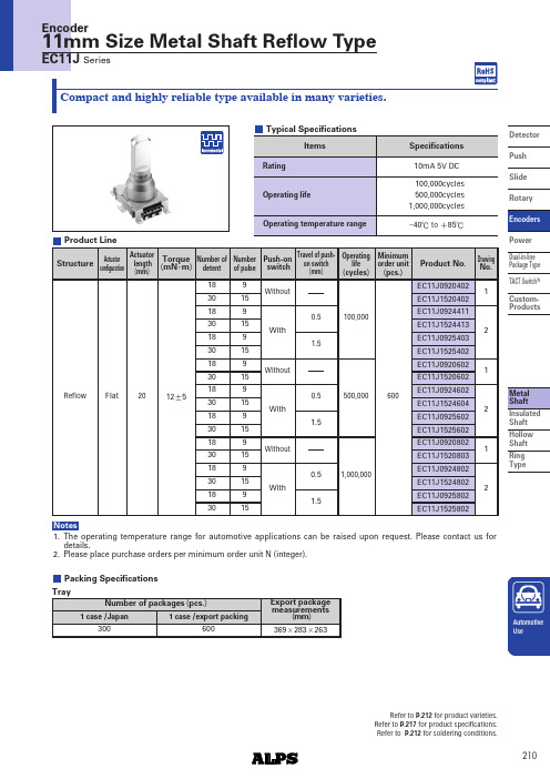
Shaft Hollow Shaft Ring TypeDetectorPushSlide Rotary PowerDual-in-line Package Type TACT Switch TM Custom-Products1.The operating temperature range for automotive applications can be raised upon request. Please contact us for details.2.Please place purchase orders per minimum order unit N (integer).NotesProduct LineActuatorconfigurationActuatorlength (mm )Torque (mN Typical SpecificationsPacking Specifications Refer to P.212for product varieties.Refer to P.217for product specifications.Refer to P.212for soldering conditions.Shaft Hollow Shaft Ring TypeDetectorPush Slide RotaryPower Dual-in-line Package Type TACT SwitchTMCustom-ProductsReflow applicable partswith push-on switchtravel 0.5mm/1.5mmShaft Hollow Shaft Ring TypeDetector Push Slide Rotary PowerDual-in-linePackage Type TACT Switch TMCustom-ProductsEC11B Series9mm, 11mm and 20mm Size Metal Shaft EncodersShaft Hollow Shaft Ring TypeDetectorPushSlide Rotary Power Dual-in-linePackage Type TACT Switch TM Custom-ProductsEncoders〇marks in "Available for automotive use" indicate that some of the series products can work at the operatingtemperature range from -40℃to +85℃.NoteShaft Hollow Shaft Ring TypeDetectorPush SlideRotaryPower Dual-in-line Package Type TACT Switch TMCustom-ProductsUnit:mm1. Single-shaft Type Shaft Dimensions1.The highlighted figures in shaft types refer to Product Specifications in P.215.2.Products other than those listed in the above chart are also available. Please contact us for detailsNotesExample of Reflow Soldering Condition1. Heating method: Double heating method with infrared heater.2. Temperature measurement: Thermocouple 0.1 to 0.2φCA (K )or CC (T )at soldering portion (copper foil surface ). A heat resisting tapeshould be used for fixed measurement.3. Temperature profile300200100RoomtemperatureT e m p e r a t u r e (ûC )1.The condition mentioned above is the temperature on the mounting surface of a PC board. There are cases wherethe PC board's temperature greatly differs from that of the switch, depending on the PC board's material, size,thickness, etc. The above-stated conditions shall also apply to switch surface temperatures.2.Soldering conditions differ depending on reflow soldering machines. You are requested to verify the soldering conditions thoroughly beforehand.Notes11mm Size Metal Shaft Long Life Encoders。
SICK增量旋转编码器选型手册

43.1 (1.70)
Ø 60 (2.36) 3 x 120°
Ø0.05 C
其它公差遵循DIN ISO 2768-mk标准 电缆直径- =5.6±0.2mm 弯曲半径 R=30mm
3 x M4 (6-deep)
Ø 48±0.05 (1.89)
夹紧法兰型外形尺寸图,M12 或 M23 插头式
3 x M4 Ø 48±0.05 (1.89) (6-deep)
01000 01024 01250
00200 02048
B型-可选择的分辨率 00050 00100 00200 00250
00300 00314 00360
00500 00512 00720
01000 01024 01250
00200 02048 02500 03600
04000 04096 05000
外壳防护等级IEC60529
质量 EMC5)
DFS60 实心轴,夹紧法兰型 O/ 60mm O/ 10 x 19 mm 0,5 Ncm 0,3 Ncm 6,2 gcm2
5 x 10⁵ rad/s2 径向 轴向 3 x 10⁹ 圈
90% 冲击3) 振动4) 外壳部分 实心轴部分 0.3kg
E
10,000 min-1 80 N 40 N
DFS60全系列产 品
DFS60夹紧法 兰型 外形 尺 寸 : 10× 19mm
DFS60伺服法 ቤተ መጻሕፍቲ ባይዱ型
运
外形尺寸: 6×10mm
动
控
制
DFS60盲孔型
传
轴径范围: 8- 15mm
感
器
分辨率: 电气输出接口: 最大转动速度: 工作温度范围: 最大输出频率: 外壳防护等级:
西门子编码器技术说明书
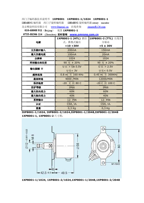
1XP8001-1/1024, 1XP8001-2/1024,1XP8001-1/2048,1XP8001-2/2048
1XP8001 西门子编码器 1XP8001-1/1024(推荐型号) 实际照片 1XP8001-1
北京顺途科技有限公司 在线查询 shunto@
010-68008 911(Beijing) 现货 1XP8001-1 0755-88306 114 (Shenzhen) 实时查询
西门子编码器技术说明书 1XP8001 1XP8001-1/1024 1XP8001-1
SIEMENS 编码器 西门子旋转编码器 SIEMENS 旋转编码器 rotary encoder
北京顺途科技有限公司 在线查询 shunto@
010-68008 911(Beijing) 现货 1XP8001-1
0755-88306 114 (Shenzhen) 实时查询
1XP8001-1 (HTL) 推拉 1XP8001-2 (ТTL) 长线差
电源
式、推挽式输出
分驱动+10 Fra bibliotek30V+5 ± 30V
无负载时输入
200mA
150mA
最大负载电流
100mA
20mA
分辨率
1024
1024
两相输出相位差
90 度 ± 20%
90 度 ± 20%
输出振幅 U
U 高 > Uв-3.5V U 低< 3V
U 高 > 2.5V U 低< 0.5V
频率范围
0.8 мс 至 160 KHz
0.45 мс 至 300KHz
最高转速
9000 /MIN
