+MSW_DRV_Battery_Charging_V1.00
WM_W800_入门手册说明书
WM_W800_入门手册V1.2北京联盛德微电子有限责任公司(winner micro)地址:北京市海淀区阜成路67号银都大厦1802电话:+86-10-62161900公司网址:文档修改记录版本修订时间修订记录作者审核V0.12019/9/25[C]创建文档CuiycV0.22020/6/12增加cygwin编译环境CuiycV0.32020/7/8统一字体CuiycV1.02020/8/4添加硬件开发板CuiycV1.12020/11/5更新高速接口介绍RayCuiycV1.22021/2/4推荐使用IDE为CDK,不再维护CDS的工程目录文档修改记录 (2)目录 (3)1概述 (5)2准备工作 (5)3w800开发板简介 (6)4w800编译环境搭建 (7)4.1w800工具链 (7)4.2开发环境安装 (7)4.2.1Windows (7)4.2.2Linux (9)4.2.3Mac OS (10)5SDK工程获取 (10)6SDK工程编译 (10)6.1Windows (10)6.1.1Ubuntu虚拟机 (10)6.2Linux (11)6.3mac os (11)7固件烧录 (11)7.1Window下的操作步骤 (11)7.2Linux下升级步骤 (15)7.3Mac os下升级步骤 (15)8串口调试 (15)9w800 sdk如何开始编写用户程序 (15)9.1用户入口 (15)9.2demo如何使用 (16)9.3at指令如何使用 (16)1概述指导如何用户搭建w800硬件开发的软件环境,通过示例工程展示如何编译、下载固件到w800开发板等操作步骤。
该手册基于W800的ARDUINO开发板进行介绍及示例的升级运行。
w800是一款基于XT804内核SoC,支持功能:⚫ 2.4G Wi-Fi⚫蓝牙⚫内置多种数字接口(QFlash,外扩PSRAM,UART,GPIO,I²C,PWM,I²S,7816,SDIO,HSPI,TouchSensor)⚫支持多种硬件加解密算法(RC4,DES,3DES,AES,RSA,MD5,SHA1)⚫内置安全功能2准备工作硬件:⚫w800开发板⚫USB数据线(Micro USB)⚫PC(Windows、linux或Mac OS)软件:⚫工具链,用于编译w800代码⚫编译工具⚫w800 sdk⚫串口工具(支持xmodem协议)⚫代码编辑器3w800开发板简介W800 Arduino开发板,提供了如下接口:⚫I2C&I2S接口⚫Uart0&SWD调试接口⚫SPI&Uart1通信接口⚫PWM接口⚫SIM 接口⚫GPIO⚫Micro USB 接口用户通过Micro USB口与上位机相连,通过UART0口进行固件烧录。
中兴交换机配置

一、系统的启动过程如下。
1、上电后,首先进行硬件启动,当硬件检测无误后,管理终端上出现下列信息:Welcome to use ZTE eCarrier!!Copyright(c) 2004-2006, ZTE Co。
, Ltd.System Booting..。
.。
CPU: S3C45010 ARM7TDMIBSP version: 1.2/0Creation date: Feb 11 2004, 09:37:01Press any key to stop auto-boot。
..72、出现上述信息后,等待大约7 秒,用户可以在这段时间内按任意键进入boot 状态,修改启动参数.当系统在规定时间未检测到用户输入时,系统便开始自动加载版本,并提示下列信息:auto—booting。
..boot device : secEndunit number : 0processor number : 0host name : tigerfile name : vxWorksinet on ethernet (e) : 10.40.92。
106host inet (h) : 10。
40.92.105flags (f) : 0x80Attaching to TFFS.。
done。
Loading version:/kernel.。
.1459932 + 75292 + 6358852Starting at 0x1656e0...Attaching interface lo0。
.。
done(省略)Welcome !ZTE Corporation。
All rights reserved.login:adminpassword:*********3、系统启动成功后,出现提示符login:,要求输入登录用户名和密码,缺省用户名是admin,密码是zhongxing。
二、配置开始工作1.打开超级终端,输入连接的名称,如ZXR10,并选择一个图标。
PowerFlex 20-HIM-A6 20-HIM-C6S HIM 固件版本 2.006 发布说明
Release Notes20-HIM-A6 / -C6S HIM Firmware Revision 2.006Catalog Numbers 20-HIM-A6, 20-HIM-C6S HIMThis release note describes major revision 2, minor revision 6 of firmware for the PowerFlex® 20-HIM-A6 and 20-HIM-C6S HIM (Human Interface Module).The following information is included in this document: EnhancementsThis firmware revision includes support for the PowerFlex 755TM, 755TR, and 755TL drives.Corrected Anomalies This section describes the anomalies that are corrected in this revision offirmware.•This firmware revision fixes an anomaly where the Element names were repeated in a Group, and Group names were repeated in a File. The HIMdisplay no longer shows repeated Elements and Groups.•In previous firmware revisions, the "Security is Enabled" notification appeared if a clear fault command was initiated on a write-protected HIMport. This notification no longer appears, and the fault is cleared correctly.•In previous firmware revisions, cities such as Istanbul and Johannesburg were options in the "Americas" region during time zone setup for thePowerFlex 753 and 755 drives. This firmware revision fixes the anomalyand the cities no longer appear as options in the incorrect region.Topic Page Enhancements 1Corrected Anomalies 1Known Anomalies 2Determining Firmware Revision 3Updating the Firmware 5Restrictions 7Compatible Revisions 72Known Anomalies CopyCat and PowerFlex 755T ProductsCopyCat does not directly support the following parameters in port 0 ofPowerFlex 755T products:•33 [VoltageClass Cfg]•35 [Duty Rating Cfg]•46 [Velocity Units]•65 [Pri MtrCtrl Mode]•67 [Sec MtrCtrl Mode]•70 [Application Sel]Changes to these parameters in port 0 determine which parameters are in otherports. Changes to these parameters require a power cycle to take effect.Therefore, CopyCat cannot properly download to non-0 ports without a powercycle after downloading to port 0.The work around for this problem is a two-step CopyCat download. Perform aCopyCat download, then cycle power, then repeat the CopyCat download. Thefirst download configures port 0. The second download configures the otherports.Escape Key Causes HIM Crash on PowerFlex 755T ProductsPowerFlex 755T products do not support Process Display. The HIM does notproperly recognize this. Pushing the soft ESC button on the main screen causesthe HIM to attempt to move to the Process Display screen. On PowerFlex 755Tproducts, this cause the HIM to crash and reboot. T o reset the HIM, continue topress the ESC button until the HIM resets.HIM Loses Least Significant Bit (LSB) of Manual Reference PreloadWhen a switch from automatic reference to manual reference moves is triggeredby a digital input, the HIM loses the LSB of the preloaded reference. For examplewhen moving to manual control with an automatic reference of 2.00 Hz, theHIM preloads the manual reference as 1.79 Hz.3Determining Firmware Revision This section describes procedures to determine the firmware revision of your PowerFlex 20-HIM-A6 or 20-HIM-C6S HIM.Using the 20-HIM-A6 or 20-HIM-C6S HIMUsing Connected Components Workbench Software1.Go online with the HIM connected to the drive by using a 1203-USBconverter or an EtherNet/IP network connection.unch the Connected Components W orkbench™ software.3.In the Device T oolbox right pane, select Discover, and click BrowseConnections.The Connection Browser appears.4.Expand the tree view as needed and select the 20-HIM-A6 or20-HIM-C6S HIM that is connected to the drive.5.Click OK.Connected Components Workbench software connects to the HIM.46.Create any database files if needed (for later use when offline), add theHIM to the Project Organizer left pane, and open the Device Detailswindow for the HIM (see Figure 1).Figure 1 Connected Components Workbench Screen with Device DetailsThe HIM firmware revision (for example, 2.003) is shown below the HIMpicture (circled in red in the graphic).Using DriveExecutive Softwareunch the DriveExecutive™ software.2.Go online with the drive connected to the HIM by using a 1203-USBconverter or an EtherNet/IP network connection.3.In the DriveExecutive tree view, select the 20-HIM-A6 or 20-HIM-C6SHIM (see Figure 2).4.Click the information iconto display the adapter Properties screen.55.The ‘Revision’ field shows the present revision of the adapter firmware (forexample, 2.003).Figure 2 DriveExecutive Window with Information Icon and Device PropertiesUpdating the Firmware Note: The PowerFlex 755T products do not support the DPI option (the HIMis a DPI option) flashing.This section describes procedures to update the adapter firmware. Flash kits fordrives, communication adapters, and peripherals are provided on theAllen-Bradley W eb Updates site at/support/abdrives/webupdate. Updating can be performedby using a 1203-USB converter. For information about how to connect to yourdrive, see its respective user manual. It can be viewed and downloaded on theLiterature Library website at .ATTENTION: Risk of permanent equipment damage exists. Once an update has beenstarted, do not remove power from the drive until after the download has completedand the HIM has reinitialized with the connected drive. If power is removed before thisoccurs, the HIM may be permanently damaged. A HIM that has been damaged in thisway cannot be repaired.6Installing the Flash Kit1.Go to the Allen-Bradley Web Updates site at /support/abdrives/webupdate and install the flash kitfor the PowerFlex 20-HIM-A6 or 20-HIM-C6S HIM, which alsoautomatically installs the ControlFLASH software on your computer.Y ou are now ready to use ControlFLASH or DriveExecutive software toupdate the firmware.2.See the respective section and follow the instructions.Using ControlFLASH Software to Update Firmware1.With the Flash Kit installed, choose Start > (All) Programs > Flash Programming T ools > ControlFLASH to launch the ControlFLASHsoftware.2.On the ControlFLASH Welcome screen, click Next >.3.Choose the appropriate 20-HIM-x6 [connection type] update from the list of available updates.4.Click Next >.5.Expand the tree view for the communication path you are using, and select the drive icon that represents the drive that is connected to the HIM youare updating.6.Click OK.7.If the Multiple Assemblies Found window appears, select ‘Port X - 20-HIM-x6’ from the list and click OK.If this window does not appear, proceed with step 8.8.With the Firmware Revision window displayed, select ‘2.006.xx [language]’ from the list of available updates.9.Click Next >.IMPORTANT Connected Components Workbench software is not intended to be used as a firmware update tool, therefore it cannot be used. The recommended tool to use is ControlFLASH™ software, which is downloaded automatically when the respective firmware revision file isdownloaded from the Allen-Bradley updates website to your computer.IMPORTANT This update may cause the HIM parameters to revert to their default values. You maywant to save your configuration by using the HIM CopyCat feature or DriveExecutivesoftware before updating.710.Follow the remaining screen prompts until the update procedure completes and displays the new firmware revision ing DriveExecutive Software to Update Firmware 1.With the Flash Kit installed (see Installing the Flash Kit on page 6), launch DriveExecutive software.2.Go online with the drive connected to the HIM by using a 1203-USB converter or an EtherNet/IP network connection.3.In the DriveExecutive tree view, select the 20-HIM-x6.4.Click the information icon (see Figure 2) to display the HIM Properties screen.5.On the HIM Properties screen, click the Component Details tab.6.Click Flash Update to start the update.7.Select the 20-HIM-x6 from the list of available devices.8.Click Next >.9.Select ‘2.006.xx [language]’ from the list of available updates.10.Click Next >.11.Follow the remaining screen prompts until the update procedure completes and displays the new firmware revision 2.006.RestrictionsNo restrictions apply to this revision of patible Revisions T o use this revision of firmware, update your tools and devices as needed.IMPORTANT This update may cause the HIM parameters to revert to their default values. You may want to save your configuration using DriveExecutive software or the HIM CopyCat feature before updating.Tool/Device Version RequiredDriveExecutive software 5.01 or laterPowerFlex 7-Class drive all versions compatible20-HIM-A6 / -C6S HIM all versions compatibleRSLinx® Classic software 2.43 or laterConnected Components Workbench 1.02 or laterRockwell Otomasyon Ticaret A.Ş., Kar Plaza İş Merkezi E Blok Kat:6 34752 İçerenköy, İstanbul, T el: +90 (216) 5698400Publication 20HIM-RN013A-EN-P - May 2017Copyright © 2017 Rockwell Automation, Inc. All rights reserved. Printed in the U.S.A.Rockwell Automation SupportUse the following resources to access support information.Documentation FeedbackY our comments will help us serve your documentation needs better. If you have any suggestions on how to improve this document, complete the How Are W e Doing? form at /idc/groups/literature/documents/du/ra-du002_-en-e.pdf .Technical Support CenterKnowledgebase Articles, How-to Videos, FAQs, Chat, User Forums, and Product Notification Updates.https:/// Local Technical Support Phone NumbersLocate the phone number for your country./global/support/get-support-now.page Direct Dial CodesFind the Direct Dial Code for your product. Use the code to route your call directly to a technical support engineer./global/support/direct-dial.page Literature LibraryInstallation Instructions, Manuals, Brochures, and Technical Data./global/literature-library/overview.page Product Compatibility and DownloadCenter (PCDC)Get help determining how products interact, check features and capabilities, and find associated firmware./global/support/pcdc.page Allen-Bradley, Connected Components Workbench, ControlFLASH, DriveExecutive, PowerFlex, Rockwell Automation, Rockwell Software, and RSLinx are trademarks of Rockwell Automation, Inc.EtherNet/IP is a trademark of ODVA, Inc.Trademarks not belonging to Rockwell Automation are property of their respective companies.Rockwell Automation maintains current product environmental information on its website at/rockwellautomation/about-us/sustainability-ethics/product-environmental-compliance.page .。
keithley(吉时利)2450,2460中文手册

不能将仪器和附件连接到人体上。
进行任何维护之前,要断开电源线和所有测试电缆。
为了持续避免电击和火灾,电网电路中的替换组件(包括电源转换器、测试引线和输入插头)必须从美国吉时利仪器 (Keithley Instruments) 公司购买。如果类型和额定值相同,也可以使用通过了国家相应安全认证的标准保险丝。只要与原组件相当,其他与 安全无关的组件可以在别的供应商处购买(注意,选定的部件应只在美国吉时利仪器 (Keithley Instruments) 公司购买,以保持产 品的精度和功能)。如果不确定替换组件的适应性,联系美国吉时利仪器 (Keithley Instruments) 公司办事处以获得详细信息。
TSP®、TSP-Link® 和 TSP-Net® 是美国吉时利仪器 (Keithley Instruments) 公司的商标。所有吉时 利仪器 (Keithley Instruments) 产品名称均为 Keithley Instruments, Inc. 的商标或注册商标。其他品
牌名称为其各自所有人的商标或注册商标。 © 1994 - 2013,Lua 5.0 软件及其关联文档的版权归 Tecgraf, PUC-Rio 所有。可以在 Lua 许可网
Model 2460 交互式 SourceMeter® 仪器
用户手册
© 2015, Keithley Instruments Cleveland, Ohio, U.S.A. 保留所有权利。
未经美国吉时利仪器 (Keithley Instruments) 公司事先书面同意,严禁对本文所含全部或部分信息进 行任何未经授权的复制、影印或使用。
符号表示连接到设备框架的连接端子。
如果产品上有此
符号,则表明显示屏灯管中使用了泵。请注意必须按照联邦、州和本地法律处理这类灯管。
三星手机GT-I9008刷机亲测教程
三星手机GT-I9008刷机亲测教程三星手机GT-I9008刷机亲测教程自用的三星I9008移动定制机,因烦定制程序太多,后台老自动运行一些不必要的软件,用卓大师root后,删了像移动电视、飞信、移动导航等一些定制程序,没想手机出问题了,每次开机或打开某个程序后退到桌面就黑屏,只显示第一行的信息提示栏,要几分钟才能重新调出桌面,而且电板只能用4个多小时了,没办法只好追求刷机了。
可查了好多资料,网上很少有机油刷这个机的,有些论坛转载别人的刷机贴也没说得太详细,经过两天反复研究,整理出较为可操作的步骤,并历尽千辛万苦下载到I9008ZMKG1:最新版刷机包。
并亲刷成功,使用两天没出啥问题。
现将刷机过程整理出来,供机油参考。
慎重提示,刷机有风险,动手需谨慎。
本人刷机成功不代表每台机都一定能成功刷机,虽然这里我提供的软件、驱动和刷机包都是本人亲测过的,但刷机成功与否还会与所用的电脑、操作系统、数据线等其他条件有关,所以特别提醒,许多经别人亲测没问题的刷机动作,自己刷成砖的大有人在。
当然,也没必要过度担心,大凡仔细研究透了过程,严格按步骤操作,成功的概率还是很高的。
一、刷前准备和注意事项:1.确保手机电池电量大于50%;2.手机内的用户数据已备份;3.刷机过程中,手机绝不能出现掉电、断线的情况,否则会造成手机损坏的情况出现。
刷机用的电脑最好用笔记本,禁用电脑的休眠模式,充满电,电池和外接电源同时供电,防止出现电脑意外断电;4.刷机过程中不要对手机进行操作,不要将手机与电脑断开连接。
5.这里提供的刷机包版本为:I9008ZMKG1。
版本查看方式:打开手机“设置”→“关于设备”就可查看到“型号、硬件版本、软件版本、基带版本”等信息。
二、刷机所需的料:1. 电脑一台(本人用的是三星超级本,WIN7家庭普通版64位操作系统);2. I9008手机数据线一根;把下载来的这些文件放到同一个文件夹,方便查找调用。
三、刷机操作步骤:第一步:安装刷机驱动程序到电脑把下载来的SAMSUNG_Mobile_USB_DRIVER_v1.6.rar解压缩,然后打开解压得到的文件夹,双击setup.exe文件,按提示安装驱动程序(这时不需连接手机),见下图,安装完毕确定重启电脑。
黑苹果MAC安装

本地化语言(选择您的首选语言)• iDeneb Essential System (系统基本软件,必选)• iDeneb Patches 10.5.7 Ready• Bootloader and DSDT (启动引导与DSDT补丁,选择一个启动引导即可)⁃ Chameleon v1.0.12 (这是变色龙1.0.12与PCEFI9)⁃ Chameleon v2 (这是变色龙v2的与PCEFI9)⁃DSDT Patcher (This is Chameleon DSDT Patcher. If you want make a dsdt patch select this voice.)• LeopardAMD (如果你的是基于AMD的系统,请必须选择,如果你选择的是Qoopz, AnV, V oodoo的内核,可以不选这个修补程序)• Fix (这里有一些系统的修复补丁)⁃ ACPI/SSE2 Fix (如果您的ACPI有问题,如果您的CPU只支持SSE2 ,您可以选择此修复程序。
您可以尝试用DSDT修修复ACPI的问题,如果您有选择Qoopz ,AnV或V oodoo 的内核,若果你没有ACPI的问题,则不需要此修补程序。
)⁃ACPI_SMC_Fix (这是一个修正删除ACPI_SMC_PlatformPlugin.kext的补丁,在某些情况下它可能会导致内核不稳,如果您选择此修复程序,很可能您的系统启动将会缓慢)⁃ AppleSMBIOS (在组驱动中包含不同版本的AppleSMBIOS.kext)⁃ AppleSMBIOS 667 (如果您的内存频率是667的话,请选择这个驱动)⁃ AppleSMBIOS 800 (如果您的内存频率是800的话,请选择这个驱动)⁃ AppleSMBIOS 1066 (如果您的内存频率是1066的话,请选择这个驱动)⁃ AppleSMBIOS 1333 ((如果您的内存频率是DDR3 1333的话,请选择这个驱动))⁃ AppleSMBIOS 1.0.1 ( V ersione Tiger ) (旧版本的AppleSMBIOS 1.0.1作者:Netkas)⁃ AppleSMBIOS 1.0.13 (AppleSMBIOS 版本1.0.13 作者:Netkas)⁃ AppleSMBIOS iMac (iMac使用的AppleSMBIOS)⁃ AppleSMBIOS Macbook (Macbook使用的AppleSMBIOS)⁃ AppleSMBIOS Mac Pro (Mac Pro使用的AppleSMBIOS)⁃ CPUS=1 Fix (此补丁将设置您的CPU为单核,如果您的电脑反复重启)⁃Firewire Remove (此修补程序将删除所有火线驱动器,您可以选择此驱动程序,如果在启动后出现错误的FireWire设备提示)⁃ idlehalt_Fix ( idehalt=0 cpus=2 ) ( nForce 520 ) (这个补丁将修正的nForce 520芯片。
HighPoint 数据RAID配置和FnL监控软件安装指南(Windows)说明书
SRD7101P/SRD7101PB /SRD7204P /SRD7104P/ SRD7104PB/SRD7140P/SRD7140PB /CRD7104PB /CRD7101PB Driver & FnL Monitor Software Installation Guide (Windows)Version v1.00Copyright © 2021 HighPoint Technologies, Inc.All rights reservedContentsOverview (1)Prerequisites for a Data-RAID Configuration (2)Installing the Device Driver (3)1.Verify that Windows recognizes the controller (3)2.Download the Device Driver (3)3.Install the Device Driver (4)Updating the Device Driver (6)1.Check the Driver version (6)2.Download the Device Driver (7)3.Shutdown and Remove the Device (7)4.Uninstall the old Device Driver (7)5.Install the new Device Driver (9)Uninstalling the Device Driver (11)Installing the FnL Management Software (FnL Monitor & CLI) (12)Uninstalling the FnL Management Software (13)Troubleshooting (15)The FnL Monitor will not start after double-clicking the desktop icon. (15)BSOD (Blue Screen of Death) (16)How to Turn off Quick Shutdown for Windows (16)Controller and Drive Detection Issues (18)Appendix (19)How to Collect Debug View Logs (19)How to Collect INF Logs (20)How to Collect System Logs (21)Collecting Windows Dump Files (22)OverviewThis guide includes important hardware/software requirements, installation & upgrade procedures, and troubleshooting tips for using SRD7101P/SRD7101PB/SRD7204P/SRD7104P/SRD7104PB/SRD7140P/ SRD7140PB/CRD7104PB/CRD7101PB NVMe AIC RAID Drives with a Windows operating system. PrerequisitesThis section describes the base hardware and software requirements for the SRD7101P/SRD7101PB/ SRD7204P/SRD7104P/SRD7104PB/SRD7140P/SRD7140PB/CRD7104PB/CRD7101PB PCIe 3.0 NVMe AIC RAID Drives.Driver InstallationThis section covers driver installation, driver upgrade and driver uninstallation procedures for SRD7101P/ SRD7101PB/SRD7204P/SRD7104P/SRD7104PB/SRD7140P/SRD7140PB/CRD7104PB/CRD7101PB NVMe AIC RAID Drives.Management Software InstallationThis section explains how to download and install the SRD7101P/SRD7101PB/SRD7204P/SRD7104P/ SRD7104PB/SRD7140P/SRD7140PB/CRD7104PB/CRD7101PB FnL Monitor Management Software S uite for Windows operating systems. The download includes both the Web RAID Management Interface (FnL Monitor), and the CLI (Command Line Interface).TroubleshootingPlease consult this section if you encounter any difficulties installing or using the SRD7101P/ SRD7204P SRD7101PB/ SRD7104P/SRD7104PB/SRD7140P/SRD7140PB/CRD7104PB/CRD7101PBNVMe AIC RAID Drives. It includes descriptions and solutions for commonly reported technical issues.AppendixA selection of useful information and web links for the SRD7101P/SRD7101PB/SRD7204P/SRD7104P/ SRD7104PB/SRD7140P/SRD7140PB/CRD7104PB/CRD7101PB NVMe AIC RAID Drives.Prerequisites for a Data-RAID ConfigurationThe SRD7101P/SRD7101PB/SRD7204P/SRD7104P/SRD7104PB/SRD7140P/SRD7140PB/CRD7104PB/CRD7101PB NVMe AIC RAID Drives can support Data-RAID arrays. In order to usera Data-RAID array, you will need the following:1. A PCIe 3.0 slot with x8 or x16 lanes. The SRD7104P/SRD7104PB/SRD7101P/SRD7101PB/SRD7140P/SRD7140PB/CRD7104PB/CRD7101PB must be installed into a PCIe 3.0 slot with x16 dedicated lanes, The SRD7204P can be installed into a PCIe 3.0 x8 or x16 slot.2.Make sure any non-HighPoint drivers are uninstalled for any SSD’s hosted by the FnLseries RAID controllers. 3rd party software and manufacturer provided drivers may prevent the FnL from functioning properly.Warnings:1)Failing to remove the AIC Drive and SSD’s when uninstalling the driver may result in dataloss.2)Always make sure the FnL driver is installed before moving a FnL series NVMe AIC RAIDDrives & RAID array to another Windows system.Windows operating systems will always load the default NVMe support after the FnL driver has been uninstalled, or if it detects the present of a card when no driver has been loaded – this driver will only recognize the NVMe SSD’s as separate disks.If the SSD’s are recognized separately, any data they contain may be lost – this includes RAIDconfiguration data.Installing the Device DriverThe following section discusses driver installation for a non-bootable NVMe configuration.1.Verify that Windows recognizes the controllerAfter installing the FnL controller into the motherboard, power on the computer, boot the Windows operating system, and open Device Manager.A.Expand the Disk drives tab. Each NVMe SSD’s installed into the SRD7101P/SRD7101PB/SRD7204P/SRD7104P/SRD7104PB/SRD7140P/SRD7140PB/ CRD7104PB/CRD7101PBcontroller should be displayed here.B.Expand the Storage Controllers tab. You should see a “Standard NVM Express Controller”entry for each NVMe SSD that is installed into the AIC RAID Drive.Example screenshot SRD7104:AB2.Download the Device DriverDownload the appropriate FnL driver from the NVMe AIC RAID Drives Software Downloads webpage.SRD7101P/SRD7101PB:https:///srd7101p-overviewSRD7104P/SRD7104PB:https:///srd7104p-overviewSRD7204P:https:///srd7204p-overviewSRD7140P/SRD7140PB:https:///srd7140p-overviewCRD7101PB:https:///crd7101pb-overviewCRD7104PB:https:///crd7104pb-overview3.Install the Device DriverA.Locate the driver download and open the file.B.Double-click setup.Note: If installation does not start, you may have to manually start setup using AdministratorPrivileges. Right-click setup, select Run as Administrator from the menu, and confirm the pop-up window to proceed.After driver installation is complete, click OK to reboot.C.Once Windows has rebooted, open Device Manager to check the status of the driver.Expand Storage controllers and click on the HighPoint NVMe RAID Controller entry. View the properties and click the Driver tab:Example screenshot (SRD7104)Note: The driver revision shown in the screenshots may not correspond with current software releases. Please make sure to download the latest driver updates from the product’s Software Updates page.D.First, make sure the FnL Monitor has been installed (see FnL Monitor install). Open the FnLMonitor and make sure the SSD.’s / arrays are properly recognized.Note: Please refer to Appendix A to verify that your Device Manager entries correspond with the driver version you have installed.Updating the Device DriverNote: Before attempting to update the driver entry, ensure that the AIC RAID Drive is removed from the motherboard.1.Check the Driver versionOpen Device Manager to check the current driver version. Expand Storage controllers and click on the HighPoint NVMe RAID Controller entry. View the properties and click the Driver tab:Example screenshot (SRD7104)2.Download the Device DriverDownload the latest driver from the controller’s Software Downloads webpage.SRD7101P/SRD7101PB:https:///srd7101p-overviewSRD7104P/SRD7104PB:https:///srd7104p-overviewSRD7204P:https:///srd7204p-overviewSRD7140P/SRD7140PB:https:///srd7140p-overviewCRD7101PB:https:///crd7101pb-overviewCRD7104PB:https:///crd7104pb-overview3.Shutdown and Remove the DeviceA.Power down the system and remove the NVMe AIC RAID Drives from the motherboard.Note: Failing to remove the FnL controller from the motherboard during the uninstall process may result in data loss.Whenever the driver is uninstalled, Windows will attempt to install the default NVMe support,which may corrupt the RAID configurations and any data stored on SSD’s hosted by the FnLcontroller.B.Power on the system and boot Windows.4.Uninstall the old Device DriverA.Access Control Panel and select Programs→ Programs and Features, and click on the HighPointNVMe Driver entry.B.Click Uninstall/ChangeIf the HPT controller is not removed from the motherboard during the uninstall process, Windows will notify you that RAID data may be destroyed.C.After uninstalling the driver, click OK to reboot.D.After Windows has rebooted, access Control Panel to make sure the driver has been uninstalled.If there are no HighPoint NVMe RAID Driver entries present, the driver has been successfully uninstalled:5.Install the new Device DriverA.Locate the driver download and open the file.B.Double-click setup.Note: If the update does not start, you may have to manually start setup using AdministratorPrivileges. Right-click setup, select Run as Administrator from the menu, and confirm the pop-up window to proceed.C.Windows will notify you that the driver is already installed. Click OK to reboot.D.After entering the system, shut down the system.In the shutdown state, connect the FnLcontroller to the motherboard.E.Boot into the system.F.Once Windows has rebooted, open Device Manager to check the status of the driver. ExpandStorage controllers and click on the HighPoint NVMe RAID Controller entry. View theproperties and click the Driver tab:Note: The driver revision shown in the screenshots may not correspond with current software releases. Please make sure to download the latest driver updates from the product’s Software Updates page.G.First, make sure the FnL Monitor has been installed (see FnL Monitor install). Open the FnLMonitor and make sure the SSD.’s / arrays are properly recognized.For Example: SRD7204Uninstalling the Device Driver1.Power down the system and remove the NVMe AIC RAID Drives from the motherboard.Note: Failing to remove the FnL controller from the motherboard during the uninstall process may result in data loss. Whenever the driver is uninstalled, Windows will attempt to install the default NVMe support, which may corrupt the RAID configurations and any data stored on SSD’s hosted by the FnL controller.2.Power on the system and boot Windows.3.Access Control Panel and select Programs→ Programs and Features, and click on the HighPointNVMe Driver entry.4.Click Uninstall/Change5.After uninstalling the driver, click OK to reboot.6.After Windows has rebooted, access Control Panel to make sure the driver has been uninstalled. Ifthere are no HighPoint NVMe RAID Driver entries present, the driver has been successfullyuninstalledInstalling the FnL Management Software (FnL Monitor & CLI)The HighPoint FnL Management Software (FnL Monitor and CLI utilities) are used to monitor NVMe SSD’s hosted by the NVMe AIC RAID Drives. Download the latest software package from the HighPoint website:SRD7101P/SRD7101PB:https:///srd7101p-overviewSRD7104P/SRD7104PB:https:///srd7104p-overviewSRD7204P:https:///srd7204p-overviewSRD7140P/SRD7140PB:https:///srd7140p-overviewCRD7101PB:https:///crd7101pb-overviewCRD7104PB:https:///crd7104pb-overview1.Extract the package and double-click the FnL Monitor program to install the software.2.Once installed, locate the Management icon on the desktop and double-click to start the FnL Monitorinterface.Uninstalling the FnL Management Software1.Access Control Panel and select Programs→ Programs and Features, and click on the FnL Monitorentry.2.Click Uninstall/Change3.After uninstalling the driver, click Finish.TroubleshootingNote: When troubleshooting your NVMe AIC RAID Drives, make sure all of the Prerequisites have been met before proceeding.The FnL Monitor will not start after double-clicking the desktop icon.1.This is often the result of a missing driver or improperly installed driver. Open Device Managerand check under Storage Controllers.If the Driver is properly installed, you should see a HighPoint NVMe Controller entry forNVMe AIC RAID Drives, followed by HighPoint NVMe RAID Controller entry:Example screenshot (SRD7104)Note: The driver revision shown in the screenshots may not correspond with current software releases.Please make sure to download the latest driver updates from the product’s Software Updates page.2.You should also check to make sure hptsvr is running under Task Management → Services. Ifthe status of hptsvr process is Stopped, right-click on this entry and select Start from the menu:BSOD (Blue Screen of Death)There are three scenarios in which a BSOD may occur with AIC RAID DriveWindows displays a BSOD when the AIC RAID Drive is installed.If you are running Windows 10, please make sure that any Quick Shutdown options are disabled – these features can cause a BSOD when the AIC RAID Drive is installed into or removed from your motherboard. BSODs can be avoided by completely powering off your system.How to Turn off Quick Shutdown for Windowse administrator privileges to access the Command Prompt utility:b.Enter the following command and press Enter:powercfg / h offc.To make sure the setting has been disabled, enter the following command and pressEnter:powercfg / ad.Shut down the computer and remove the AIC RAID Drive from the motherboard;e.Restart the system and open the SRD7101P/SRD7101PB/SRD7204P/SRD7104P/SRD7104PB/SRD7140P/SRD7140PB/CRD7104PB/CRD7101PB driver download.f.Double-click Setup to reinstall the driver; if you are prompted to uninstall the driver, youwill need to follow the prompts and restart. After rebooting, double-click Setup once more to install the driver.After the driver installation is complete, shut down the computer. The AIC RAID Drive insert into the motherboard PCIe slot.g.Power on the system, boot Windows and access the FnL Monitor; if the FnL Monitorcan't connect, you need to restart again.h.If it fails to start the second time, please access our Online Support portal and submit asupport ticket.Note:If you are running a Server version of windows, and encounter a BSOD at bootup,please collect the following information: Windows version & build numbers, MemoryDump and System event Log1. A BSOD is encountered when installing the driver:If you experience a BSOD during driver installation, please collect the following information:Memory Dump, INF log, Debug Log, System Event log, and submit a new support ticket via our Online Support Portal.2.If Windows reports that driver installation has failed:a.Please collect these debugging information: INF log, Debug Log, DeviceManager/Storage Controller screen shot, System Event logNote:If you experience a BSOD or error when installing the driver, please ensure that any Quick Shutdown options are not enabled– Quick shutdown can cause a BSOD when removing theAIC RAID Drive from your motherboard, and plugging it back in. BSODs can be avoided bycompletely powering off your system:Controller and Drive Detection Issues•If your motherboard or Windows is unable to detect the NVMe AIC RAID Drives or NVMe SS D’s, please shutdown the system and try moving the NVMe AIC RAID Drives to another PCIeslot.•Make sure any unrelated NVMe devices are removed from the motherboard while troubleshooting the SRD7101P/SRD7101PB/SRD7204P/SRD7104P/SRD7104PB/SRD7140P/SRD7140PB/CRD7104PB/CRD7101PB NVMe AIC RAID Drives.AppendixHow to Collect Debug View LogsIf other troubleshooting steps fail to solve the problem, we suspect that the driver and management softwa re cannot establish a connection with the SRD7101P/SRD7101PB/SRD7204P/SRD7104P/SRD7104PB/ SRD7140P/SRD7140PB/CRD7104PB/CRD7101PB NVMe AIC RAID Drives. We will provide you with a Debug version of the driver to collect information about the problem you areexperiencing.To install the Debug driver, follow the standard driver installation procedure (please refer to theSRD7101P/SRD7101PB/SRD7204P/SRD7104P/SRD7104PB/SRD7140P/SRD7140PB/CRD7104PB/ CRD7101PB NVMe AIC RAID Drives User Guide). After installing the driver, follow the steps below:1.Download the DebugView utility from https:///files/DebugView.zip.2.Unzip, right-click on the icon, and run DebugView with administrator privileges. Select CaptureWin32, Capture Kernel, Enable Verbose Kernel Output, and Pass in the Capture toolbar.3.If the utility displays an “access denied” message, rename the following file:C:\Windows\System32\drivers\Dbgv.sys For example, rename it to “Dbgv.sys1”, i.e change the file type.4.Save the information printed by DebugView and send this to our support department.5.If required, we will provide management software information collection tools for the NVMeRAID Manager interface.How to Collect INF Logs1.Go to drive C→ Windows→ INF, and locate the setuppapi.dev and setupapi.setup logs:INF logs can be used to check what kind of software has been installed into the Windowssystems.2.Please access Device Manager, Storage Controllers, and check the properties for the HighPointentry. Click on Driver Details and take a screenshot – include this with the log files you submit for your support case.How to Collect System LogsIn addition to DebugView logs, System Logs can aid our Support department diagnose and resolve the support issues you have submitted. The System Log typically records errors, device failures, and software or driver related incidents. This information can help our engineers narrow down or even identify the source of the problem you are experiencing.System Log1.Click the Windows button towards the bottom left-hand corner of your desktop, and click on theSearch field.2.Type Event Viewer and click the icon as shown below:3.Expand the Windows Log folder and select System:4.Select Save All Events as… and save the .evtx file in an easy to find location.Collecting Windows Dump FilesWindows Dump files are snap shots that show which processes were running at the time of the event or failure. If possible, locate and upload the following files to your support case:•Memory.dmp•Minidump.dmpTo locate the dump files, check the C:\Windows directory and search for Memory.dmp andMinidump.dmp:。
INIC3619_Datasheet_V1.00

Revision 1.00 August 14, 2013 Initio Corporation
Revision 1.00
Page 1 of 28
INIC-3619 Datasheet _______________________________________________________________________________
批注本地保存成功开通会员云端永久保存去开通
INIC-3619 Datasheet _______________________________________________________________________________
INIC-3619 USB 3.0 SATA Bridge Datasheet
Contents
1 Introduction.......................................................................................................................................................................4 1.1 Feature Summary.......................................................................................................................................................4 1.2 Firmware Support..........................
i.MXRT1170-EVK 板防篡改功能使用指南说明书

1简介本文档介绍了防篡改功能(Tamper Function)的使用。
篡改检测可用于保护隐私或敏感信息。
当设备遇到未经授权的开启或修改时,将触发防篡改功能把关键信息清空。
部分I.MXRT 系列支持SNVS 模块的防篡改功能。
本指南旨在介绍i.MXRT1170- EVK 板防篡改功能的使用。
2概述该功能支持外部和内部两种防篡改检测。
•内部提供电压、温度、时钟监控用于防篡改检测。
•外部采用防篡改引脚检测设备是否遇到未经授权的开启或篡改。
当监测条件参数超出范围时,将触发防篡改功能将关键信息清零,包括GPR 寄存器、安全RAM 和可清零主密钥(ZMK),同时将安全状态机(SSM)切换到“失败”状态。
3防篡改功能介绍i.MXRT1173支持内部和外部防篡改检测。
•十个外部防篡改检测引脚,包括无源和有源篡改检测。
•三种内部防篡改检测:包括电压、时钟和温度检测。
3.1外部防篡改检测外部篡改检测是通过芯片引脚提供特殊机制来决定设备是否遇到了未经授权的打开或篡改。
芯片内部将引脚接收到的信号与所期望的信号电平进行比较,一旦不相等,将触发防篡改机制。
当使用单个防篡改管脚来检测时,为无源检测;当使用成对的防篡改信号,一个用来发送信号,另外一个用来检测,为有源检测。
该芯片最多支持10个无源篡改检测引脚,或者5对有源篡改检测引脚。
如果篡改检测引脚是浮空的并且外部连接很长的走线,这个会带来额外的电流消耗,推荐使能内部的上拉/下拉电阻来避免额外的电流增加。
•毛刺过滤器每个篡改检测引脚都支持启用或不启用毛刺过滤器,并可以通过配置 ETGFx 字段来设置过滤器宽度,脉冲过滤器为宽度 128~32640 的 SRTC 时钟,启用脉冲滤波器后,外部引脚上任何等于或小于数字脉冲过滤器宽度的信号都会被过滤。
图 1显示了毛刺过滤器工作示例。
目录1简介.................................................12概述.................................................13防篡改功能介绍...............................13.1外部防篡改检测............................13.2内部防篡改检测............................34例程.................................................44.1外部防篡改检测............................54.2电压检测.......................................54.3时钟检测.......................................64.4温度检测.......................................65参考资料 (66)版本历史 (6)AN13078防篡改功能使用指南Rev. 1 — 11 May, 2021Application Note图 1.脉冲滤波器工作示例•无源篡改检测每个引脚都支持用于检测与设定电平值是否一致。
MC33771B_SDS 电池单元控制器 IC 产品概要说明书

MC33771B_SDS电池单元控制器第1 简介33771是一款SMARTMOS锂离子电池单元控制器IC,专为混合动力汽车(HEV)和电动汽车(EV)等汽车应用以及能源存储系统(ESS)和不间断电源(UPS)系统等工业应用而设计。
该器件对差分电池单元电压和电流执行ADC转换,并进行电池库仑计数和电池温度测量。
该信息通过串行外设接口(SPI)或变压器隔离(TPL)以数字方式传输到微控制器进行处理。
2 特性●工作电压9.6 V ≤ V PWR≤ 61.6 V,瞬态电压75V●7至14个电池单元管理●隔离式2.0 Mbps差分通信或4.0 Mbps SPI●初始化时可寻址●0.8 mV最大总电压测量误差●同步电池单元电压/电流测量和库仑计数●电池组总电压测量●7个GPIO/温度传感器输入● 5.0 V基准电源输出,5.0 mA电流能力●自动过压/欠压和温度检测,可路由至故障引脚●集成睡眠模式过压/欠压和温度监控●板载300 mA被动单元平衡,带诊断功能●支持热插拔●内部和外部故障(如断路、短路和泄漏)检测●支持ISO 26262,最高达到ASIL D安全系统●与最多可支持6个电池单元的MC33772完全兼容●符合AEC-Q100要求3 简化应用电路图图1. 简化应用电路图,SPI用例图2. 简化应用电路图,TPL用例4 应用●汽车:48 V和高压电池组●电动自行车和电动踏板车●能源存储系统●不间断电源(UPS)5 订购信息5.1 器件编号定义MC33771B x y z AE/R25.2 器件编号列表本小节描述可订购器件编号及其差异。
官网上提供可订购器件编号。
如需确定该器件的可订购器件编号,请访问。
表2. 高级系列可订购器件表温度范围为-40至105 °C表3. 基础系列可订购器件表温度范围为-40至105 °C表4. 特级系列可订购器件表温度范围为-40至105 °C6 引脚配置信息6.1 引脚示意图图3. 引脚示意图6.2 引脚定义7 基本产品特性7.1 额定值和工作要求的关系工作电压范围与以AGND引脚为基准的VPWR引脚相关。
三星i9100使用小技巧汇总

三星i9100使用小技巧汇总三星i9100使用小技巧汇总Download Mode=刷机模式Recovery Mode=恢复模式CWM Recovery Mode=CWM 恢复模式【功能强大的第三放恢复模式】1.刷机模式:进入方法:音量下+HOME+POWER ON 出现第一界面后再按下音量上进入电脑上用Odin3刷.tar 或.tar.md5文件的时候用2. 恢复模式:进入方法:音量上++HOME+POWER ON 官方的恢复模式(3e)只能用来清除数据【平时说的双wipe 就是进这模式】reboot system now:重启手机apply sdcard/update.zip:升级SD卡中的update.zipwipe data 清除数据相当于恢复出厂设置6)按下“Start”开始刷机刷机过程中平台上方会有进度条7)刷机平台出现绿色“PASS”后刷机完成手机会自动重启三:Galaxy S II GT-I9100 ROM可精简列表以及精简教程Galaxy S II GT-I9100 ROM可精简列表以及精简教程注意:动手精简之前请做好备份有同名的ODEX文件要一起删除这是我自己精简的列表供大家参考欢迎大家补充一:使用RE文件管理器精简REguanliqimeihuaban_Root_Explo rer__mumayihanhua__V2.16_muma yi_8530e.apk (264.99 KB)精简路径:system/app AnalogClock.apk 时钟插件AxT9IME.apk 內建T9輸入法BuddiesNow.apk 好友现况ChocoEUKor.apk 某種英文特殊字型Days.apk Samsung的Widget其中一個日歷DigitalClock.apk 双时钟插件Dlna.apk 無線分享裝置DualClock.apk 時鐘插件Email.apk 这个不用介绍了吧EmailWidget.apk email插件GameHub.apkGenieWidget.apkKobo.apkMaps.apk 谷歌地图Memo.apk 备忘录MiniDiary.apk 迷你日志MinimalHome.apkPolarisOffice.apkPostIt.apkPressReader.apk 阅读的ReadersHub.apk SamsungApps.apk 这个也不用介绍了吧SamsungAppsUNAService.apk SamsungIM.apk 三星的即时信息SamsungWidget_News.apk 新闻插件SamsungWidget_ProgramMonitor. apk 任务管理器桌面插件SamsungWidget_StockClock.apk 这个应该是股票插件SevenEngine.apk 社交圈物体SnsAccountFb.apk 社交圈物体SnsAccountLi.apk 社交圈物体SnsAccountMs.apk 社交圈物体SnsAccountPk.apk 社交圈物体SnsAccountTw.apk 社交圈物体SocialHub.apkStk.apk SIM卡工具Street.apk 谷歌的街景Swype.apk 一种输入法syncmldm.apkTalk.apkTrimApp.apkVideoEditor.apk VoiceRecorder.apk 语音记录VoiceSearch.apk 语音谈话VoiceToGo.apk 语音搜索YouTube.apkZinio.apk二:使用CWM精简一步到位无须你再手动删除了适用于Deodex版ROM【system/app 下无ODEX文件的】:update1.zip (157.25 KB)适用于官方原版ROM【system/app下有ODEX文件的】:update.zip (157.39 KB)操作方法:1.下载以上相对的精简包后复制到手机内置SD卡上2.进入应用程序打开CWM图标如下图:3.选择:Flash update 如下图:4.选择update1.zip 如下图:5.点击Flash6.等待手机重启恭喜你精简完成[四:Samsung Galaxy S II GT-I9100 指令全集四:Samsung Galaxy S II GT-I9100 指令全集Samsung Galaxy S II GT-I9100 指令全集部分指令请慎用英文版Obtain/Change Device Information*#06# (Display IMEI number)*#1234# (Display current firmware)*2767*4387264636# (To display product code)*#272*imei#* (Display/change CSC code)or *#272*HHMM#**#12580*369# (SW & HW Info) *#44336# (Sofware Version Info) Reset*#*#7780#*#* or *#7780# (Factory soft reset)*2767*3855# (Factory hard reset to ROM firmware default settings)Firmware Tools*#2663# (TSP / TSK firmware update)*#34971539# (Camera Firmware Update)*#7412365# (Camera Firmware Menu)or *#*#34971539#*#**#03# (NAND Flash S/N)General Testing/Debugging*#0*# (General Test Mode)*#*#4636#*#* (Diagnostic and general settings mode)*#*#197328640#*#* (Service mode main menu)*#7353# (Quick Test Menu) Wireless*#232337# (Bluetooth Address) *#232331# (Bluetooth Test Mode) *#232338# (WLAN MAC Address) *#232339# (WLAN Test Mode)*#526# (WLAN Engineering Mode)*#528# (WLAN Engineering Mode) GPS*#1575# (GPS Control Menu)*#*#1472365#*#* (GPS test settings)Sensors*#0588# (Proximity Sensor Test Mode)*#0589# (Light Sensor Test Mode) Audio*#0673# (Audio Test Mode)*#0283# (Audio Loopback Control)*#0289# (Melody Test Mode) Buttons*#7594# (Remap Shutdown to End Call TSK)Battery*#0228# (Battery status: capacity, voltage, temperature)Other Test/Debugging (many of these items are access ible via the service/test menus listed above)*#32489# (Ciphering Info)*#0842# (Vibra Motor Test Mode) *#0782# (Real Time Clock Test) *#2263# (RF Band Selection)*#9090# (Diagnostic ConfiguratioN)*#7284# (USB I2C Mode Control) *#872564# (USB Logging Control) *#4238378# (GCF Configuration) *#3214789650# (LBS Test Mode) *#745# (RIL Dump Menu)*#746# (Debug Dump Menu)*#9900# (System Dump Mode)*#273283*255*3282*# (Data Create Menu)*#273283*255*663282*# (Data Create SD Card)*#3282*727336*# (Data Usage Status)*#80# (Unknown)*#07# (Test History)*#3214789# (GCF Mode Status) *#272886# (Auto Answer Selection)*#8736364# (OTA Update Menu) *#301279# (HSDPA/HSUPA Control Menu)*2767*4387264636# (Sellout SMS / PCODE view)*#7465625# (View Phone Lock Status)*7465625*638*# (Configure Network Lock MCC/MNC)#7465625*638*# (Insert Network Lock Keycode)*7465625*782*# (Configure Network Lock NSP)#7465625*782*# (Insert Partitial Network Lock Keycode)*7465625*77*# (Insert Network Lock Keycode SP)#7465625*77*# (Insert Operator Lock Keycode)*7465625*27*# (Insert Network Lock Keycode NSP/CP)#7465625*27*# (Insert Content Provider Keycode)谷歌翻译获取/更改设备信息*#06#(显示IMEI号码)*#1234#(显示当前固件)* 2767 * 4387264636#(要显示产品代码)* IMEI号*#272#*(显示/更改留学基金委代码)或*#272#* * HHMM*#12580 * 369#(软件&硬件信息)*#44336#(软件版本信息)复位*#*#7780#*#*或*#7780#(厂软复位)* 2767 * 3855#(工厂硬复位的ROM 固件默认设置)固件工具*#2663#(重钙/邓肇坚固件更新)*#34971539#(相机固件更新)*#7412365#(相机固件菜单)或*#*#34971539#*#**#03#(NAND快闪记忆体的S / N)的通用测试/调试*#0 *#(综合测试模式)*#*#4636#*#*(诊断和模式一般设置)*#*#197328640#*#*(服务模式下的主菜单)*#7353#(快速测试菜单)无线*#232337#(蓝牙地址)*#232331#(蓝牙测试模式)*#232338#(无线局域网MAC地址)*#232339#(WLAN测试模式)*#526#(无线局域网工程模式)*#528#(无线局域网工程模式)全球定位系统*#1575#(GPS控制菜单)*#*#1472365 *#*#(GPS测试设置)传感器*#0588#(接近传感器测试模式)*#0589#(光感应器测试模式)音频*#0673#(音频测试模式)*#0283#(音频回传控制)*#0289#(旋律测试模式)按钮*#7594#(重映射关机以结束通话邓肇坚)电池*#0228#(电池状态:容量,电压,温度)其他测试/调试(其中许多项目都可以通过其服务/测试上面列出菜单)*#32489#(通话加密信息)*#0842#(抑振电机测试模式)*#0782#(实时时钟测试)*#2263#(射频波段选择)*#9090#(诊断配置)*#7284#(I2C模式的USB控制)*#872564#(记录的USB控制)*#4238378#(GCF的配置)*#3214789650#(磅测试模式)*#745#(RIL的转储菜单)*#746#(调试转储菜单)*#9900#(系统转储模式)*#273283 * 255 * 3282 *#(数据创建菜单)*#273283 * 255 * 663282 *#(数据创建SD卡)*#3282 * 727336 *#(资料使用情况)*#80#(未知)*#07#(测试历史)*#3214789#(GCF的模式状态)*#272886#(自动应答选择)*#8736364#(OTA更新菜单)*#301279#(HSDPA / HSUPA的控制菜单)* 2767 * 4387264636#(出卖短信/ PCODE观点)*#7465625#(查看手机锁定状态)* 7465625 * 638 *#(配置网络锁定的MCC /跨国公司)#7465625 * 638 *#(插入网络锁密码)* 7465625 * 782 *#(配置网络锁定新型干法)#7465625 * 782 *#(插入Partitial 网络锁定密码)* 7465625 * 77 *#(插入网络锁定密钥号码SP法)#7465625 * 77 *#(插入操作锁密码)* 7465625 * 27 *#(插入网络锁定密钥号码新型干法/处长)#7465625 * 27 *#(插入内容提供商密码)Galaxy S II GT-I9100 常见问题解答我如何知道我手机的ROM版本是多少答:手机拨号输入:*#1234# 即可显示你手机的ROM版本PDA PHONE CSCI9100如何自定义来电铃声、短信铃声、闹钟铃声?答:在sd卡上新建3个文件夹:alarms,闹铃;ringtones,来电铃声;notifications,短信铃声。
Monolithic Power eMotion System 智能电机模块评估套件 EVKT-MS
EVKT-MSM942038-24EVKT-MSM942038-24eMotion System TM Smart Motor ModuleEvaluation KitEvaluation Kit EVKT-MSM942038-24 ContentsPart Number EVKT-MSM942038-24Diameter (mm) 42 Power (W)38 Typical Voltage (V)24 InterfaceRS485# Part Number Item Quantity 1EVKT-MSM942038-24 BLDC motor withMMP742038-24 smart motor module installed 1 2eMotion System TMcommunication kitUSB communication interface with cable1FEATURESThe EVKT-MSM942038-24 evaluation kit is part of a family of fully integrated smart motor solutions for servo motor applications. This 42mm (NEMA 17), 38W motor integrates a brushless DC motor and a smart motor module. The user can program the system to operate in speed control mode, position control mode, or torque control mode. Two control interface options are available: an RS485 interface and a PULSE/DIR interface. Easy-to-use GUI software provides flexibility by allowing users to optimize the design online through the RS485 control interface. The parameters are saved in the motor module ’s non-volatile memory. A design guide for the GUI is available for download at .The smart motor modules can be ordered separately for customization into different motor types. The MMP742038-24 is the driver module part number used in the kit.The datasheet for the MMP742038-24 is available for download at .∙ 18V to 36V Input Voltage Range ∙ Max 38W Continuous Power Output ∙ 0.12N-m Rated Torque (0.36N-m Peak Torque)∙0.3° Position Resolution ∙ RS485 Interface and PULSE/DIR Interface ∙ Position, Speed, and Torque Control Modes ∙ Operating Temperature: 0°C to 70°C (Power Derated > 40°C) ∙ Storage Temperature: -40°C to +125°CORDERING INFORMATIONDESCRIPTIONEVKT-MSM942038-24 – eMOTION SYSTEM TM EVALUATION KITSmart Motor Module Evaluation KitParameter Condition Value UnitsInput voltage24 VOutput power0°C to40°C38 WPositionresolution0.3 °Nominal speed3000 rpmNominal torque0.12 N-mRotor inertia24 g-cm2Diameter42 mmShaft diameter 5 mmLength Body only 40 mmWeight300 gHARDWARE CONNECTIONSRECOMMENDED OPERATING CONDITIONSInput voltage ................................. 18V to 36VControl interface voltage ................ 0V to 5.5VMax pulse frequency .......................... 500kHzRS485 A/B voltage ........................ 0V to 5.5VRS485 common mode voltage ................±15VOperation temperature................. 0°C to 70°CStorage temperature ............. -40°C to +125°C EVALUATION KIT SPECIFICATIONSEVKT-MSM942038-24 – eMOTION SYSTEM TM EVALUATION KIT8 9 10 11 121 2 3 45 6 7Fault IndicationPower On IndicationT A = 25°C, V IN = 24V, unless otherwise noted.Pin NumberDesignation Pin Description RS485 Interface 1 EXT_5V5V input for firmware programming 2 B RS485 node B 3 AGND RS485 ground 4 A RS485 node A Power Interface5 GND Power ground6 R- Shunt resistor return node7 VIN Input power supply Control Interface8 COM- Common return 9 EN+ Enable input 10 PEND+ Position end output11 PUL+ Pulse input 12DIR+Direction inputPIN CONFIGURATIONTYPICAL PERFORMANCE CHARACTERISTICSEVKT-MSM942038-24 – eMOTION SYSTEM TM EVALUATION KITMECHANICAL DRAWINGEVKT-MSM942038-24。
亿维自动化 X系列BD扩展板使用说明书

3.4. X-2AO-BD 产品说明书 ............................................................................................................ 19
3.4.1. 产品概述 ............................................................................................................................ 19
2.1.4. 模拟量 BD 扩展板地址对照表........................................................................................... 7
3. BD 扩展板详细参数..................................................................................................................................... 9
服务热线:4000 300 890
3.1.4. 安装及接线图 .................................................................................................................... 10
3.1.5. 应用说明 .............................................................................................................................11
MSW_DRV_Camera_V1.00

MSTAR DRIVER (EMMI)CameraTOPIC•工作原理简介•点亮•功能实现•关于自动识别•FAQ工作原理简介•原理图简介•行同步和场同步原理图简介原理图简介•POWER:VCORE/VIO(DVDD)/AVDD/GND •I2C:SDL/SCL(4.7K PULL UP)•ITU601:D0-D7/HSYNC/VSYNC/PCLK •PWD/RST/MCLK行同步和场同步点亮•调试环境/资料准备•调试工具简介•软件版本和Sensor Table 的关系•逐步修改Sensor Table •BaseBand 端需的修改调试环境/资料准备•Sensor 的datasheet •模组的规格书•初始化Register 设置/Reference code •验证OK 的模组/目标板/运行正常的SW调试工具简介调试工具简介•编辑sensor table •生成cus file•Sensor 在线调试软件版本和Sensor Table 的关系•Notice :请务必注意软件版本和Sensor Table 版本的匹配逐步修改Sensor Table•header[16] •u16Total_length •u8Sensor_Inputformat •u8Sensor_RGBformat •u8Sensor_type •u8Module_type •u8Sensor_freq_index_pre •u8Icp_freq_index_pre •u8Isp_freq_index_pre •u8Scl_freq_index_pre •u8I2c_control •u8I2c_mode •u8Data_length •u8M2S_address •u8M2S_clockfactor •u8reset_mode •u8GPIOpin •u8sensorreset_delay •u8VSync_polarity •u8HSync_polarity •u8Sensor_clockpolarity •u8Sensor_RGBYUVorder •u16Sensor_slaveaddress •u16Sensor_IDaddress_L •u16Sensor_ID_L •u16Sensor_IDaddress_H •u16Sensor_ID_H •u16Sensor_inittable_length •sensor_initial_table[1023]逐步修改Sensor Table•u16Preview_tablelength •Preview_table[512] •u16SENSOR_WIDTH •u16SENSOR_HEIGHT •u16PREVIEW_WIDTH •u16PREVIEW_HEIGHT •sensor_ID_page_enable •senosr_ID_page_length •senosr_ID_page_table[4] •u16Sensor_inittable_length_EX1 •sensor_initial_table_EX1[256] •u16Sensor_inittable_length_EX2•sensor_initial_table_EX2[256]BaseBand 端需要的修改•配置是否为双摄像头—options.mak •配置PWD 及Reset Pin•配置POWER --Csl_cam.cPreview follow常见问题及分析•进入Camera 后,提示“错误”•可以进入Camera ,但是黑屏•可以进入Camera ,颜色不对进入Camera 后,提示“错误”•原因基本是CAMERA 没有识别到•I2C 是否有上拉?•各个POWER 信号正常?•Rst 信号正常?•PWD 信号正常?•MCLK 信号正常?•SENSOR 焊接/飞线/模组确认可以进入Camera ,但是黑屏•播放一段Video ,测试下多媒体功能是否正确•VSYNC/HSYNC 极性反都可能导致黑屏可以进入Camera ,颜色不对•YUV Order •Sensor 本身工作是否正常•PCLK 极性是否正确•双Camera/ATV 干扰功能实现•CAPTURE •NIGHT MODE AND BANDING AND FRAME RATE •PC-CAM •VC •EV •MWBCAPTURE•Capture Size <= Preview Size •Sensor Full Size>=Capture Size > Preview Size •Capture Size > Senosr Full Size •Exposure and VBlankingCapture Size <= Preview Size•Preview_captureSensor Full Size>=Capture Size >Preview Size •u8Icp_freq_index_cap •u8Isp_freq_index_cap •u8Scl_freq_index_cap •Capture_table •Cap_antiflicker50HZ •Cap_antiflicker60HZ •u8Preview_Cap_factor •u8Sensor_freq_capCapture Size > Senosr Full Size•u8Icp_freq_index_cap •u8Isp_freq_index_cap •u8Scl_freq_index_cap •Capture_table •Cap_antiflicker50HZ •Cap_antiflicker60HZ •u8CapZoom_page_enable •CapZoom_page_table •u8CapZoom_SCLK_Idx •CapZoomPLL_table •u8Preview_CapZoom_factor •CapZoom_antiflicker50HZ •CapZoom_antiflicker60HZu8Preview_Cap_factor and u8Preview_CapZoom_factor•在cap/cap zoom 时修改了时钟时会用到•ExposureTimePreview = X•ExposureTimeCap/CapZoom = Y那么:Factor = ((Factor&0xC0)>>6)*100 + (Factor&0x3f)*100/64Y=(X*Factor+50)/100Exposure and VBlanking•u8EXP_register_number •u16EXP_L •u8EXP_L_startbit •u8EXP_L_stopbit •u16EXP_M •u8EXP_M_startbit •u8EXP_M_stopbit •u16EXP_H •u8EXP_H_startbit •u8EXP_H_stopbit •u8Insert_Vblanking_flag •u8Insert_Vblanking_reg_number •u16Vblanking_register_L •u8Vblanking_register_L_startbit •u8Vblanking_register_L_endtbit •u16Vblanking_register_H •u8Vblanking_register_H_startbit •u8Vblanking_register_H_endtbit •u16Vblanking_valueNIGHT MODE AND BANDING AND FRAMERATE •Framerate_pccam_table•Framerate_video_table•Framerate_preview_tableSequence:60HZ Normal mode60HZ Night mode50HZ Normal mode50HZ Night modeNIGHT MODE AND BANDING AND FRAMERATE •Framerate Table 在什么时候用?1.Operation mode(PC-CAM/VIDEO/PREVIEW)2.50HZ/60HZ SETUP3.Night Mode/Normal ModeCapture 的常见问题•拍大尺寸的照片会失败•拍摄大尺寸照片时,照片的亮度和preview 的不一致PC-CAMPC-CAM 吃的是Preview 的流程,所以,如果实现了Preview ,这时PC-CAM 应该可以工作,只是,需要在csl_usb.c 中开控制它的电源VC同PC-CAM 相似,VC(视频聊天)中关于摄像头的Power 控制也需要单独控制,在csl_vc.c 中有如下函数:EV•u8AE_target_level •AE_target_table •u8AE_target_level_fast •AE_target_table_fastMWB•u8Manual_WBmode•Manual_AWBtable关于自动识别•每次开机时都会去识别摄像头•Reset 和PWD 的MGPIO 是由B2传给M3的•如果没有识别到的话,B2不会进行打开电源等动作---测信号/Log 抓不到•可以支持多个摄像头FAQReadId 是0xff如果在M3的Log 中,出现了这个提示,典型的Sensor 的I2C 没有PASS,一般来说,我们需要做的是:对比Sensor 的规格书,看看Pin 脚定义是否正确测量Power 信号是否正确测试Reset/PowerDown 信号是否正确仔细的阅读Sensor 的Datasheet ,看看设备的从地址及ID 是否正确测试有无MCLK 信号注意如果是支持了自动识别的话,这个信号只能在开机的时候抓Header 很重要不同版本的Header 是不同的,有时候肯呢个会拿到前版本的dat 文件,这时,要使用Tool 来查看当前版本的header 是什么,然后加以转换ID 对了啊,怎么进去就黑屏呢?这时,需要继续check vsync/hsync/pclk/等信号的正确性,如果设置的Preview 频率很高,降频看看也是个好办法,要不,就在fn_isp_dsr_new 看看是否有帧中断。
kdz刷机教程
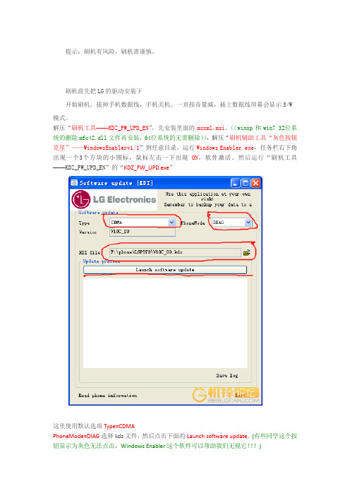
提示:刷机有风险,刷机需谨慎。
刷机前先把LG的驱动安装下开始刷机。
拔掉手机数据线,手机关机。
一直按音量减,插上数据线屏幕会显示S/W 模式。
解压“刷机工具——KDZ_FW_UPD_EN”,先安装里面的msxml.msi。
((winxp和win7 32位系统的删除mfc42.dll文件再安装,64位系统的无需删除)),解压“刷机辅助工具“灰色按钮克星”——WindowsEnablerv1.1”到任意目录,运行Windows Enabler.exe,任务栏右下角出现一个3个方块的小图标,鼠标左击一下出现ON,软件激活。
然后运行“刷机工具——KDZ_FW_UPD_EN”的“KDZ_FW_UPD.exe”这里使用默认选项Type=CDMAPhoneMode=DIAG选择kdz文件,然后点击下面的Launch software update。
(有些同学这个按钮显示为灰色无法点击,Windows Enabler这个软件可以帮助我们无视它!!!)按钮起初一段时间程序会没有响应,不要怕也不要强行关闭,这是软件正在解包kdz。
过会窗口会出现很多提示,类似下面11:45:09 : CDMA: wParam = 2004, lParam = 8811:45:09 : Model Dll Msg Not Found(2004, 88)11:45:11 : CDMA: wParam = 2004, lParam = 8911:45:11 : Model Dll Msg Not Found(2004, 89)11:45:15 : CDMA: wParam = 2004, lParam = 9011:45:15 : Model Dll Msg Not Found(2004, 90)11:45:17 : CDMA: wParam = 2004, lParam = 9011:45:17 : Model Dll Msg Not Found(2004, 90)11:45:19 : CDMA: wParam = 2004, lParam = 9111:45:19 : Model Dll Msg Not Found(2004, 91)11:45:21 : CDMA: wParam = 2004, lParam = 9111:45:21 : Model Dll Msg Not Found(2004, 91)11:45:23 : CDMA: wParam = 2004, lParam = 92大概在出现到90的时候,手机会重新启动。
G810详细刷机教程

G810刷机教程-by xlus(以下内容机友xlus/xluschen原创,转载的朋友请注明出处)俗话说:工欲善其事,必先利其器。
刷机前我们应该做好充分准备工作,多看教程,这样才能最大程度上保证爱机不变砖。
1、通过Samsung PC Studio 7备份好所有用户数据(注意在备份设置里要选“手机存储”才能备份联系人)。
2、将810的电池充满(刷机时间不长,但为安全起见,还是建议满电操作)。
3、准备好刷机所需的所有软件,包含:G818E_SS60_Downloader_Driver 驱动程序(内含PHONE_driver和PDA_driver二个文件夹)G818_Apollo v4.32A FOR China 刷机工具G810 ROM文件即刷机包(有二个文件,拿F2版来说:一个是G810DZHF2_AP.IMG,一个是G810DZHF2_CP.bin,少任何一个文件请不要刷!)一切准备就绪,啥也不说了,开刷吧?等等,别急,请花一两分钟读耐心阅读以下注意事项:1、刷机过程中请注意手机和电脑均不能断电,有条件的建议用笔记本满电操作;2、刷机中每次连接电脑时,先用数据线连好手机,然后再连电脑,断开连接时,断开电脑端即可;3、刷机过程中810蓝屏状态下无法通过开机按钮关机,请直接取下电池关机。
4、刷机全过程请不要运行任何Samsung PC Studio软件,避免出现问题。
5、二个刷机驱动有任何一个安装不成功,请不要刷机!切记,否则可能成砖头,刷机有风险!6、第二次刷机时,如果用的不是上一次刷机的USB口一定要重新安装驱动,切记!!7、若上述两个驱动中任何一个驱动安装完成后提示重启电脑的话,按提示重启;两个驱动均安装完成后强烈建议重启电脑,然后分别按1、4开机,7、*开机看下二个驱动是否正常。
如果不正常切记不要刷机!!虽然浪费点时间,但为了以防万一,还是做下吧!好了,现在我们来正式开吧:第一步,安装MODEM驱动:1、进入刷机软件包的“G818E_SS60_Downloader_Driver”文件夹,里面有两个子文件夹,进入“PHONE_driver”,点击“Setup.exe”安装MODEM驱动,如图:直接点击“Install”安装,安装完之后如图:点“确定”完成MODEM驱动在电脑上的安装;2、810关机,同时长按“7”键和“*”键后再同时按开机,直到出现蓝屏且有闪烁的“MODEM DOWNLOAD”文字时才松开,如图:2、数据线先连接810,然后连上电脑,会提示找到新硬件,然后自动安装驱动程序。
万能驱动助理v5驱动定制

设备管理器中有一个硬件的驱动未安装,打开万能驱动助理查看有哪些硬件不能识别根据未识别的硬件找到硬件id,设备管理器--双击硬件----详细信息----硬件id,将硬件id的信息全部记下来,点击硬件id的信息后用Ctrl+C复制到文档中下载sqliteadmin这个软件在WanDrv的Files文件夹下面,有一个名字为[WinXP.x86]EasyDrv.ed5db数据库文件在[WinXP.x86]EasyDrv.ed5db 文件后加上7z的后缀就可以解压出来了解压缩后得到EasyDrv.db,将EasyDrv.db复制到C盘后把文件的只读属性去掉。
将EasyDrv.db文件放在纯英文路径下这样才可以用sqliteadmin打开在右面找到硬件id对应的一行,点击编辑数据就能看到数据了。
实际上现在看到的只有ids,也就是编码,一列数字而已。
有用的在右面,拖动下面的滚动条向右或者在ids那双击就能看见你要的东西了。
如果找不到硬件id对应的一行就去other找,这样也无就要在other表中自己手动添加了IDS:是个序号,不要重复应该没有问题hwid 就是硬件ID,根据实际硬件填写name 硬件名称inf inf文件在WanDrv中的路径drvpkg 对应驱动要解压的7Z驱动包class 硬件类别date 驱动的发布时间ver 驱动的版本号在上方的过滤器列中选择Hwid,过滤器中输入查询关键字LEGACY,然后按回车键就会显示结果,核对一下自己的硬件id信息是否一致,去修改不一致的项目,全部都不一样就全部都修改。
如果增加一项新驱动信息IDS号就不要重复,只想修改驱动信息就在原有的IDS号后修改修改Hwid为*CTL7001,双击相应的数据直接改就是了,改完了点击对钩修改完成修改name为Game Port for Creative修改inf的路径为Other\VMware\gameport.inf修改完成修改drvpkg为[WinXP.x86]Drivers\Other\VMware.7zclass 和date及ver三个的信息在驱动文件gameport.inf中修改class为MEDIA修改完成修改date为07/01/2001修改完成修改ver为5.1.2600.0修改完成全部驱动信息修改完成还有一个hwid信息为LEGACY\JOYSTICK未添加进来,可以将全部hwid信息都添加的这样可以提高被识别出来的精确度。
- 1、下载文档前请自行甄别文档内容的完整性,平台不提供额外的编辑、内容补充、找答案等附加服务。
- 2、"仅部分预览"的文档,不可在线预览部分如存在完整性等问题,可反馈申请退款(可完整预览的文档不适用该条件!)。
- 3、如文档侵犯您的权益,请联系客服反馈,我们会尽快为您处理(人工客服工作时间:9:00-18:30)。
MSTAR DRIVEREMMI Battery & Charging概要1.硬件•充电电路图2.软件•充电的驱动相关信息介绍•充电事件请求信息介绍•软件设计•接口介绍•单元测试•集成测试•ADC 校准•用户可以修改的内容•电池充电概图充电电路图Battery ArchitectureBattery TaskABB TaskADCADC requestPMUS e n d d a t aCharging Battery statusAthenaI2CPMUADCSet ChargerIncenseCharger detectcharger detect充电驱动相关信息介绍(1/3)•充电相关函数(Battery 模块) 主要包括以下内容:-Service layer (API)(给上层)-提供给上层来获取电池状态。
-Charging manager-电池充电规则设定-电池状态报告-Battery event 处理-电池相关的事件,如:ADC 测量请求, ADC done 事件通知等。
-根据需要,向上层报告电池状态,如:充电开、关等事件。
充电驱动相关信息介绍(2/3)•充电规则-硬件-Trickle mode (Vbat < 2.6V)-Pre-charge mode (Vbat < 3.3V)(最低开机电压(3.4v ))-软件-CC mode (Vbat > 3.3V)(只是给硬件设置CC 或CV 的电压范围)-CV mode (when Vbat is closing to CV target set by SW)•电池充电满的标准–通过函数bat_DetectFullBattery()来判定(bat_pars.c )。
–电池充满条件-2个*(V max -V bat )<=200mV (eg: V max =4200)*I chg <Battery_Capacity/10充电驱动相关信息介绍(3/3)•充电管理–充电管理主要在函数_MdlBatManageCharging ()里面进行(bat_pars.c )。
–充电的状态列表*CHARGER_UNPLUGGED : 没有插充电器*TRICKLE_CHARGING : 充电器刚插进去时的状态,以小电流进行充电(100ma )。
*FAST_CHARGING : 充电时主要维持的状态,大电流充电模式。
(100ma~500ma )*DISCHARGE_WAIT : 充电器插入时,MMI 电池显示满图标(电池满的时候插入充电器)。
*SECURITY_WAIT : 充电满时进入的状态。
security timer starts *NO_CHARGING : 充电时,有硬件告警后进入的状态(如:过压保护)*ENOUGH_DISCHARGE_WAIT : security timer 完成后进入的状态。
充电事件请求信息介绍•电池充电相关函数在driver 层实现,为下列服务的应用层提供应用接口,例如给MMI 提供接口-Battery status service calls-To get battery level-To get charger status(充电器是否插入状态)-To get charging status (当前充电状态)-To get battery voltage-If task communication is supported in MMI-Periodic battery level report (including low-battery indication)-Charger plug-in indication and plug-out indication-Charging on indication (start charging) and charging off indication (charging complete)•The charging function is used to charge a battery while charger is plugged.-Pre-charge mode control-Not switch on power until Vbat is higher than 3.3V or more (正常使用,电压可低至3.3v ,充电开机电压为3.4v )-Full battery control-Vbat is closing to CV target after charging软件设计BAT_TASK MAEBatteryBattery Model listener更新电池显示状态,充电动画等信息SEND EVT (event 定义在mae_battery.h 中)Events are for Battery Model to notifytheir listener ()MSG产产生中断Custom.c--MdlBatAcquireBa tteryData(Sleeped Frames)SleepedFr ames 为周期,处理消息BAT_MEASURE_MSG;BAT_CHARGER _UNPLUGGED;BAT_MEASURE_MSG;BAT_CHARGER _PLUGGED;软件设计(1/3)•接口-Service call•vm_batMmiBatteryLevel_t vm_batGetLevel (void);•bool vm_batGetChargerState (void);•bool vm_batGetChargingState (void);•u16 vm_batGetVoltage(void);•u16 vm_batGetChargerVoltage(void);•u16 vm_batGetChargerCurrent(void);•s16 vm_batGetBatteryTemp(void); (-1 is returned)•s16 vm_batGetBackupBatteryVoltage(void); //("-1" is returned)-Battery status indication (in case of task communication supported)•void vm_batSubscribe(u8 mailbox)•Message type;typedef enum {BAT_LEVEL = VM_BAT_BASE, ///< message sent to indicated the battery level BAT_CHARGER_ON, ///< 当有充电器插入时,发送此消息BAT_CHARGER_OFF, ///< 当有充电器拔出时,发送此消息BAT_CHARGING_ON, ///< 当充电开始的时候,发送此消息BAT_CHARGING_OFF, ///< 当充电结束的时候,发送此消息BAT_ALARM, ///< 当有电池报警时,发送此消息BAT_LAST_EXT_MSG软件设计(2/3)•充电功能分两个模块-Battery 模块-Incense 模块•Battery 模块-API: 提供电池状态-充电管理: 充电控制-事件/请求/Timer 处理: 处理电池相关的事情与请求。
-Timer 管理: timer 事件处理(发送timer 相关的消息与监控充电状态)。
•Incense 模块-API: 提供Incense 状态-Incense 事件处理-Incense ISR: mask Incense INTCharging managerEvent/Request/Timer handlerIncense APIIncense Event Handler (Task)DRV LAYER(区别不同平台软件设计(3/3)•ADC 数据请求–An example of working model of Battery Module and Incense Module (ACD 500ms )Upper Task Battery Task Abb Task Incense ISRDrvBattStartDataAcquisition()VM_ABB_ADC_RESULT_INDincense_irq_msg_handler()_MdlBatGetAndSumBatteryData()If report软件接口(1/3) –文件列表•Incense 模块-DRV –drv_abb.c,incense_audio.c,incense_charg.c,incense_irq.c,drv_abb.c,ince nse_charg.h,incense_drv.h,etc.-HAL –hal_adc.c -mdl_abb_task.c•Athena 模块-HAL –hal_athena.c,hal_athena.h,hal_athena_reg.h -DRV –athena.c,athena.h athena_reg.h•Batt 模块-HAL -hal_batt_athena_charg.c,hal_batt_charg.h -DRV -Drv_batt.c,drv_batt.h,vm_batt.h-MIDDLEWARE -bat_cork.c, bat_pars.c,bat_msg.h,bat_pars.h,etc.软件接口(2/3) –Incense 模块•Abb Task 入口点(mdl_abb_task.c)-abb_Task()•Incense IRQ Handler (incense_irq.c)-DrvIncenseIrqHandler ()-DrvIncenseIrqPostHandler ()-incense_mask_irq()-incense_clear_irq()-incense_unmask_irq()•Athena ADC Function (athena.c)-DrvPmuAdcAcquire()-DrvPmuAdcConversionDone()-etc.•Athena Charger Function (hal_athena_adc.c)-_HalPmuSetVbatInitialVaules()-_HalPmuAdcConfigureConversion()-_HalPmuAdcReadResult()-HalPmuAdcDoneHandler()-HalPmuGetVbatValidADC()-HalPmuDetectBatteryPresence() -etc.•Athena Register Access Function (hal_athena.c)-Athena_ReadI2C()-Athena_WriteI2C()软件接口(3/3) –Batt 模块bat_pars.c•Batt Task 进入点: bat_thread_Init()/bat_Task()•Batt 模块初始化: MdlBatInit()•Batt Task 的消息处理: _MdlBatParse()•充电管理: _MdlBatManageCharging()•电池状态报告: _MdlBatReportStatus()•电池相关的API-MdlBatSubscribe()-MdlBatGetLevel()-MdlBatGetChargerState()-MdlBatGetChargingState()-MdlBatGetVoltage()-MdlBatGetChargerVoltage()-MdlBatGetChargerCurrent()Drv_batt.c•Battery Module Utilities单元测试•接口-周期性汇报电池level-电池level 和电池电压之间的映射-Battery level determination-充电器插入和拔出的通知-充电开/关通知(电池满通知(SW) )•充电规则-ADC 数据请求(减小Vbat 测量误差)-充电流程-电池满测量(HW)•系统特性-充电开机-开机电压-关机电压综合测试•关机时-插入充电器开机-充电动画-电池满通知-拔充电器后关机•开机时-如果没有充电器插入-battery level and battery 电压映射-如果充电器插入-充电器插入通知-充电动画-充电满通知-充电器拔出通知•电压过低时-电池低电压告警-电压过低,自动关机ADC Calibration•目的是提供一个系数来补偿ADC 以减少误差。
