ZDSC-2002
CCM手机摄像头组装技术

9.Illumination 30Hz mode:min.-150000 lux
15Hz mode:min.-75000 lux
Source:Matsushita/2002
10.White balance Auto/manual/IIC I/F bus
CMM鏡組的基本關係
影像高度=光學鏡組焦距x tan(semi-FOV)
簡易方式:光學鏡組焦距長為6mm,而影像高度由影像 偵測器的有效區域大小決定,最大為區域的對角線長的 一半(假設對角線長6毫米),影像高度為3mm,由公式 可以算出半視場角為tan-1(3/6)=26.5度,FOV=53度。 像素大小為 5.4 x 5.4 微米, 像素數目 6000/5.4=1100 x 1100
1.改善Epoxy覆蓋issue 2.增加厚度
OCSP模組封裝方式
1.Top glass 如何放置(Shift/tilt/rotation)?
2.點膠與膠量控制
3.間隙要控制多少(毛細/黏稠)
4.加工道次
Reference:kingpak com./2004
照相手機模組封裝方式3
TOG (Tab on glass) 優點:良率高(免打線)、高度
typically specified in the horizontal dimension ( see Figure 1). This parameter is important in determining the primary magni fication (PMAG) required to obtain a desired field of view. Note:Most analog cameras have a 4:3 (H:V) dimensional aspect ratio. FIGURE 1
有机闪烁剂1,4-双(2-甲基苯乙烯基)苯的合成、表征和稳定性
有机闪烁剂1,4-双(2-甲基苯乙烯基)苯的合成、表征和稳定性邓嘉伦;刘小成;胡丽;邱黎;蔡光威;张刚;李自勇;李翔【摘要】1,4-双(2-甲基苯乙烯基)苯(bis-MSB)应用于闪烁剂,作为波长位移剂使用.以邻二甲苯为原料,与二溴海因进行溴化反应、与三苯基膦进行叶立德反应、在叔丁醇钾存在下与对苯二甲醛发生Wittig反应,合成了目标产物bis-MSB.总收率74.9%,纯度99.9%(HPLC),其结构经HPLC、DSC、FTIR、1 HNMR、13 CNMR 确证.紫外可见吸收光谱测试表明,加入4?2-叔丁基对苯二酚(TBHQ)可显著提高bis-MSB的稳定性.【期刊名称】《化学与生物工程》【年(卷),期】2018(035)007【总页数】4页(P57-60)【关键词】1,4-双(2-甲基苯乙烯基)苯;闪烁剂;合成;表征;稳定性【作者】邓嘉伦;刘小成;胡丽;邱黎;蔡光威;张刚;李自勇;李翔【作者单位】华烁科技股份有限公司,湖北武汉 430074;华烁科技股份有限公司,湖北武汉 430074;华烁科技股份有限公司,湖北武汉 430074;华烁科技股份有限公司,湖北武汉 430074;华烁科技股份有限公司,湖北武汉 430074;华烁科技股份有限公司,湖北武汉 430074;华烁科技股份有限公司,湖北武汉 430074;华烁科技股份有限公司,湖北武汉 430074【正文语种】中文【中图分类】TQ241.21,4-双(2-甲基苯乙烯基)苯,简称bis-MSB,CAS No.13280-61-0,分子式C24H22,结构式见图1。
图1 bis-MSB的结构式Fig.1 Structural formula of bis-MSBbis-MSB属于大π键类化合物[1-4],属于有机闪烁剂,在高能电磁辐射线激发下,能发射短暂的荧光,这一光电效应广泛地应用于原子能、医学、考古、地质、探矿、生物、农业以及激光等领域[4-7]。
离体生物组织相变潜热的DSC测试

峰温 /e
相变结束 温度 /e
- 15. 3 - 11. 5 - 15. 0 - 16. 0
- 15. 1 - 6. 8 - 7. 5 - 11. 8
利用实 验中 获得的 热流 曲线 (图 2 ~ 图 5 ), 及 DSC的分析软件从而获得各组织的相变潜热, 峰温及 相变起始与结束温度. 比如在 DSC 曲线中, 相变前后 基线的切线与吸热峰 所围成的面积 ( Area) 就是试样 的相变潜热. 如表 1所示.
$q
)0
所围成 的面
积, K 为换算系数, 它跟试样与热池壁热阻 R 无关, 因 此 K 将不随温度而变化, K 的标定也只要取一种标准
物质即可.
1. 2 仪器的选择 实验选用的是 热流式 DSC, 图 1 为 DSC 原 理示
意图.
和温度校正.
2 离体生物组织相变潜热测试
2. 1 系统可靠性检验 在对离体生物组织进行测量之前, 先对去离子水
2) 实验所获得的数据无论是对于 低温保存还是 低温外科都具有一定的指导意义, 在冷冻外科疗法中
参考文献:
[ 1] 华泽钊, 任禾盛. 低温 生物医 学技术 [M ]. 北京: 科学出 版社, 1994.
[ 2] 刘金刚, 刘作斌. 低温医学 [ M ]. 北京: 人民卫生出版社, 19 93.
[ 3] M CGRATH J J, D ILLER K R Ed. Low T emperature B iotechno logy, Em erg ing A pp lications and Eng ineer ing Contr ibutions. T he W inter Annua lM ee ting of the A SM E [ Z ]. CH ICAGO, ILL INO IS, 1998.
DSC泰科(马斯康电子有限公司)

DSC
基本概念
探测器篇
探测器:对有效范围内的环境进行监测,发现异常立即向主机发送开关量。 分类 常见的探测器类型:被动红外探测器,主动红外 探测器,双鉴移动探测器,玻璃破碎探测器, 震动探测器,门磁,紧急按钮,烟感探测器, 温度感应探测器
DSC
移动探测技术移动探测技术-被动红外
探测器篇
被动红外即探测器本身不发射任何能量而只被动接受探测来自环 境的红外辐射。 被动红外探测器的核心器件1-热释电元件 被动红外探测器的核心器件
DSC
微波探测原理
探测器篇
• 微波是指频率在300MHz-300GHz范围内极高频电磁波,其波长 范围从1m到1mm。 • 微波遇到目标会出现反射。 • 如果目标距离是变化的,发出的频率和接收的频率会出现频率 差。 • 发射和接收混频产生一个新的低频信号,称多普勒信号,其频 率称为多普勒频率。 • 多普勒频率出现提示实质的移动目标
DSC
探测器篇
LC-101—CAM带黑白 彩色摄像机的防宠物被动红外探测器(1) LC-101—CAM带黑白/彩色摄像机的防宠物被动红外探测器(1) 带黑白/ 产品描述 产品描述: • • • • • 内置黑白/彩色摄像头的防宠物被动红外探测器 视频感应设备: 具有高灵敏度, 具有电子快门控制 音频感应设备: 全方位识别, 高灵敏度 探测范围可达15米 型号:黑白摄像机 LC-101-CAMBWCC 彩色摄像机 LC-101-CAMCLPAL
DSC
LC-104LC-104-PIMW
特性
• • • • • • • • • • •
探测器篇
防宠物双鉴探测器( 防宠物双鉴探测器(2)
“A”型触点和防拆开关 被动红外、微波探测“AND”/”OR”可选 微波灵敏度单独可调 PIR灵敏度单独可调 防宠物高达25Kg (55lbs) 先进的基于的ASIC 电子系统,数字信号分析 四元线性成像技术(Quad Linear Imaging Technology ) 提供身体尺寸的清晰分析,并且可以区分背景和宠物 具有温度补偿功能 基于多普勒的微波探测 独特的微波移动感应器,配有微波传输片状天线 安装高度免校准(1.8m – 2.4m)
东方电机DSC系列产品说明说明书

ON FWD *OQVU
OFF
ON REV *OQVU
OFF
*OTUBOUBOFPVT#J%JSFDUJPOBM0QFSBUJPOT
FWD %JSFDUJPO
0QFSBUJPO*NBHF
REV%JSFDUJPO
Figure 3 Operation Example of Instantaneous Bi-Directional Operations
Orientalmotor
Features and Control Technologies of the DSC Series Motor and Speed Controller Package
An “AC motor and speed controller package” is a unit product composed of a robust, single-phase induction motor, and a low noise, long life speed controller. The DSC Series is a new AC Speed Control product. In order to improve ease of use, this product is equipped with an operation panel for monitoring various functions, as well as for digital settings. The new DSC control technology also accomplishes two functions that conventional products cannot; instant reversal of single phase induction motors, and vertical drive by deceleration control (electromagnetic brake type only).
纳米颗粒尺寸、形状以及界面效应对介电和击穿场强等因素的影响

Society Chem.Mater.2010,22,1567–15781567DOI:10.1021/cm902852hNanoparticle,Size,Shape,and Interfacial Effects on Leakage Current Density,Permittivity,and Breakdown Strength of MetalOxide-Polyolefin Nanocomposites:Experiment and TheoryNeng Guo,†Sara A.DiBenedetto,†Pratyush Tewari,‡Michael nagan,*,‡Mark A.Ratner,*,†and Tobin J.Marks*,††Department of Chemistry and the Materials Research Center,Northwestern University,Evanston, Illinois60208-3113and‡Center for Dielectric Studies,Materials Research Institute,The Pennsylvania State University,University Park,Pennsylvania16802-4800Received September11,2009.Revised Manuscript Received December2,2009A series of0-3metal oxide-polyolefin nanocomposites are synthesized via in situ olefin polymeriza-tion,using the following single-site metallocene catalysts:C2-symmetric dichloro[rac-ethylenebisindenyl]-zirconium(IV),Me2Si(t BuN)(η5-C5Me4)TiCl2,and(η5-C5Me5)TiCl3immobilized on methylaluminoxane (MAO)-treated BaTiO3,ZrO2,3-mol%-yttria-stabilized zirconia,8-mol%-yttria-stabilized zirconia, sphere-shaped TiO2nanoparticles,and rod-shaped TiO2nanoparticles.The resulting composite materials are structurally characterized via X-ray diffraction(XRD),scanning electron microscopy(SEM), transmission electron microscopy(TEM),13C nuclear magnetic resonance(NMR)spectroscopy,and differential scanning calorimetry(DSC).TEM analysis shows that the nanoparticles are well-dispersed in the polymer matrix,with each individual nanoparticle surrounded by polymer.Electrical measurements reveal that most of these nanocomposites have leakage current densities of∼10-6-10-8A/cm2;relative permittivities increase as the nanoparticle volume fraction increases,with measured values as high as6.1. At the same volume fraction,rod-shaped TiO2nanoparticle-isotactic polypropylene nanocomposites exhibit significantly greater permittivities than the corresponding sphere-shaped TiO2nanoparticle-isotactic polypropylene nanocomposites.Effective medium theories fail to give a quantitative description of the capacitance behavior,but do aid substantially in interpreting the trends qualitatively.The energy storage densities of these nanocomposites are estimated to be as high as9.4J/cm3.IntroductionFuture pulsed-power and power electronic capacitors will require dielectric materials with ultimate energy storage den-sities of>30J/cm3,operating voltages of>10kV,and milli-second-microsecond charge/discharge times with reliable operation near the dielectric breakdown limit.Importantly, at2and0.2J/cm3,respectively,the operating characteristics of current-generation pulsed power and power electronic capacitors,which utilize either ceramic or polymer dielectric materials,remain significantly short of this goal.1An order-of-magnitude improvement in energy density will require the development of dramatically different types of materials, which substantially increase intrinsic dielectric energy den-sities while reliably operating as close as possible to the die-lectric breakdown limit.For simple linear response dielectric materials,the maximum energy density is defined in eq1,U e¼12εrε0E2ð1Þwhereεr is the relative dielectric permittivity,E the dielec-tric breakdown strength,andε0the vacuum permittivity (8.8542Â10-12F/m).Generally,metal oxides have large permittivities;however,they are limited by low breakdown fields.While organic materials(e.g.,polymers)can provide high breakdown strengths,their generally modest permit-tivities have limited their application.1Recently,inorganic-polymer nanocomposite materials have attracted great interest,because of their potential for high energy densities.2By integrating the complementary*Authors to whom correspondence should be addressed.E-mail addresses: mxl46@(M.T.L.),ratner@(M.A.R.),and t-marks@(T.J.M.).(1)(a)Pan,J.;Li,K.;Li,J.;Hsu,T.;Wang,Q.Appl.Phys.Lett.2009,95,022902.(b)Claude,J.;Lu,Y.;Li,K.;Wang,Q.Chem.Mater.2008, 20,2078–2080.(c)Chu,B.;Zhou,X.;Ren,K.;Neese,B.;Lin,M.;Wang,Q.;Bauer,F.;Zhang,Q.M.Science2006,313,334–336.(d) Cao,Y.;Irwin,P.C.;Younsi,K.IEEE Trans.Dielectr.Electr.Insul.2004,11,797–807.(e)Nalwa,H.S.,Ed.Handbook of Low and High Dielectric Constant Materials and Their Applications;Academic Press:New York,1999;V ol.2.(f)Sarjeant,W.J.;Zirnheld,J.;MacDougall,F.W.IEEE Trans.Plasma Sci.1998,26,1368–1392.(2)(a)Kim,P.;Doss,N.M.;Tillotson,J.P.;Hotchkiss,P.J.;Pan,M.-J.;Marder,S.R.;Li,J.;Calame,J.P.;Perry,J.W.ACS Nano 2009,3,2581–2592.(b)Li,J.;Seok,S.I.;Chu,B.;Dogan,F.;Zhang, Q.;Wang,Q.Adv.Mater.2009,21,217–221.(c)Li,J.;Claude,J.;Norena-Franco,L.E.;Selk,S.;Wang,Q.Chem.Mater.2008,20, 6304–6306.(d)Gross,S.;Camozzo,D.;Di Noto,V.;Armelao,L.;Tondello,E.Eur.Polym.J.2007,43,673–696.(e)Gilbert,L.J.;Schuman,T.P.;Dogan,F.Ceram.Trans.2006,179,17–26.(f)Rao,Y.;Wong,C.P.J.Appl.Polym.Sci.2004,92,2228–2231.(g)Dias,C.J.;Das-Gupta,D.K.IEEE Trans.Dielectr.Electr.Insul.1996,3,706–734.(h)Mammone,R.R.;Binder,M.Novel Methods For Preparing Thin,High Permittivity Polymerdielectrics for Capacitor Applica-tions;Proceedings of the34th International Power Sources Symposium, 1990,Cherry Hill,NJ;IEEE:New York,1990;pp395-398./cmPublished on Web01/05/2010 r2010American Chemical1568Chem.Mater.,Vol.22,No.4,2010Guo et al.properties of their constituents,such materials can simul-taneously derive high permittivity from the inorganic in-clusions and high breakdown strength,mechanical flexibility,facile processability,light weight,and tunability of the properties(polymer molecular weight,comonomer incorporation,viscoelastic properties,etc.)from the poly-mer host matrix.3In addition,convincing theoretical argu-ments have been made suggesting that large inclusion-matrix interfacial areas should afford greater polarization levels,dielectric response,and breakdown strength.4 Inorganic-polymer nanocomposites are typically pre-pared via mechanical blending,5solution mixing,6in situ radical polymerization,7and in situ nanoparticle syn-thesis.8However,host-guest incompatibilities intro-duced in these synthetic approaches frequently result in nanoparticle aggregation and phase separation over largelength scales,9which is detrimental to the electrical prop-erties of the composite.10Covalent grafting of the poly-mer chains to inorganic nanoparticle surfaces has alsoproven promising,leading to more effective dispersionand enhanced electrical/mechanical properties;11how-ever,such processes may not be optimally cost-effective,nor may they be easily scaled up.Furthermore,thedevelopment of accurate theoretical models for the di-electric properties of the nanocomposite must be accom-panied by a reliable experimental means to achievenanoparticle deagglomeration.In the huge industrial-scale heterogeneous or slurryolefin polymerization processes practiced today,SiO2isgenerally used as the catalyst support.12Very large localhydrostatic pressures arising from the propagating poly-olefin chains are known to effect extensive SiO2particlefracture and lead to SiO2-polyolefin composites.12Based on this observation,composite materials with enhancedmechanical properties13have been synthesized via in situpolymerizations using filler surface-anchored Ziegler-Natta or metallocene polymerization catalysts.14There-fore,we envisioned that processes meditated by rationallyselected single-site metallocene catalysts supported onferroelectric oxide nanoparticles15might disrupt ubiqui-tous and problematic nanoparticle agglomeration,16toafford homogeneously dispersed nanoparticles within thematrix of a processable,high-strength commodity poly-mer,already used extensively in energy storage capaci-tors.17Moreover,we envisioned that the methylalumino-xane(MAO)co-catalyst14i layer applied to the metaloxide nanoparticle surfaces would,after polymer workupunder ambient conditions,serve as an effective precursorfor a thin Al2O3layer to moderate the large anticipated(3)(a)Nelson,J.K.;Hu,Y.J.Phys.D:Appl.Phys.2005,38,213–222.(b)Tanaka,T.;Montanari,G.C.;M€u lhaupt,R.IEEE Trans.Dielectr.Electr.Insul.2004,11,763–784.(c)Lewis,T.J.IEEE Trans.Dielectr.Electr.Insul.1994,15,812–825.(d)Newnham,R.E.Annu.Rev.Mater.Sci.1986,16,47–68.(4)(a)Saha,S.K.Phys.Rev.B2004,69,1254161–125464.(b)Nelson,J.K.;Utracki,L.A.;MacCrone,R.K.;Reed,C.W.IEEE Conf.Electr.Insul.Dielectr.Phenomena2004,314–317.(c)Li,J.Phys.Rev.Lett.2003,90,217601/1–4.(5)(a)Subodh,G.;Deepu,V.;Mohanan,P.;Sebastian,M.T.Appl.Phys.Lett.2009,95,062903.(b)Dang,Z.;Wu,J.;Fan,L.;Nan,C.Chem.Phys.Lett.2003,376,389–394.(6)(a)Goyal,R.K.;Jagadale,P.A.;Mulik,U.P.J.Appl.Polym.Sci.2009,111,2071–2077.(b)Afzal,A.B.;Akhtar,M.J.;Nadeem,M.;Hassan,M.M.J.Phys.Chem.C2009,113,17560–17565.(c)Huang, X.Y.;Jiang,P.K.;Kim,C.U.J.Appl.Phys.2007,102,124103.(d) Parvatikar,N.;Ambika Prasad,M.V.N.J.Appl.Polym.Sci.2006, 100,1403–1405.(e)Badheka,P.;Magadala,V.;Gopi Devaraju,N.;Lee,B.I.;Kim,E.S.J.Appl.Polym.Sci.2006,99,2815–2821.(f)Xie, S.;Zhu,B.;Xu,Z.;Xu,Y.Mater.Lett.2005,59,2403–2407.(g) Schroeder,R.;Majewski,L.;Grell,M.Adv.Mater.2005,17,1535–1539.(h)Bai,Y.;Cheng,Z.;Bharti,V.;Xu,H.;Zhang,Q.Appl.Phys.Lett.2000,76,3804–3806.(7)(a)Andou,Y.;Jeong,J.-M.;Nishida,H.;Endo,T.Macromolecules2009,42,7930–7935.(b)Thomas,P.;Dwarakanath,K.;Varma,K.B.R.Synth.Met.2009,159,2128–2134.(c)Chen,Y.-M.;Lin,H.-C.;Hsu,R.-S.;Hsieh,B.-Z.;Su,Y.-A.;Sheng,Y.-J.;Lin,J.-J.Chem.Mater.2009,21,4071–4079.(d)He,A.;Wang,L.;Li,J.;Dong,J.;Han,C.C.Polymer2006,47,1767–1771.(e)Ginzburg,V.V.;Myers, K.;Malowinski,S.;Cieslinski,R.;Elwell,M.;Bernius,M.Macro-molecules2006,39,3901–3906.(f)Mizutani,T.;Arai,K.;Miyamoto, M.;Kimura,Y.J.Appl.Polym.Sci.2006,99,659–669.(g)Xiao,M.;Sun,L.;Liu,J.;Li,Y.;Gong,K.Polymer2002,43,2245–2248.(h)R.Popielarz,R.;Chiang,C.K.;Nozaki,R.;Obrzut,J.Macromolecules 2001,34,5910–5915.(8)(a)Balan,L.;Jin,M.;Malval,J.-P.;Chaumeil,H.;Defoin,A.;Vidal,L.Macromolecules2008,41,9359–9365.(b)Lu,J.;Moon,K.S.;Xu,J.;Wong,C.P.J.Mater.Chem.2006,16,1543–1548.(c)Yogo, T.;Yamamoto,T.;Sakamoto,W.;Hirano,S.J.Mater.Res.2004,19, 3290–3297.(9)(a)Vaia,R.A.;Maguire,J.F.Chem.Mater.2007,19,2736–2751.(b)Mackay,M.E.;Tuteja,A.;Duxbury,P.M.;Hawker,C.J.;Van Horn,B.;Guan,Z.;Chen,G.;Krishnan,R.S.Science2006,311,1740–1743.(c)Lin,Y.;Boeker,A.;He,J.;Sill,K.;Xiang,H.;Abetz,C.;Li,X.;Wang,J.;Emrick,T.;Long,S.;Wang,Q.;Balazs,A.;Russell,T.P.Nature2005,434,55–59.(10)(a)Stoyanov,H.;Mc Carthy,D.;Kollosche,M.;Kofod,G.Appl.Phys.Lett.2009,94,232905.(b)Chen,G.;Davies,A.E.IEEE Trans.Dielectr.Electr.Insul.2000,7,401–407.(c)Khalil,M.S.IEEE Trans.Dielectr.Electr.Insul.2000,7,261–268.(11)(a)Zhang,Y.;Ye,Z.Macromolecules2008,41,6331–6338.(b)Maliakal,A.;Katz,H.E.;Cotts,P.M.;Subramoney,S.;Mirau,P.J.Am.Chem.Soc.2005,127,14655–14662.(c)Rusa,M.;Whitesell,J.K.;Fox,M.A.Macromolecules2004,37,2766–2774.(d)Bartholome,C.;Beyou,E.;Bourgeat-Lami,E.;Chaumont,P.;Zydowicz,N.Macro-molecules2003,36,7946–7952.(e)Corbierre,M.K.;Cameron,N.S.;Sutton,M.;Mochrie,S.G.J.;Lurio,L.B.;R€u hm,A.;Lennox,R.B.J.Am.Chem.Soc.2001,123,10411–10412.(f)von Werne,T.;Patten,T.E.J.Am.Chem.Soc.2001,123,7497–7505.(g)Nuss,S.;B€o ttcher,H.;Wurm,H.;Hallensleben,M.L.Angew.Chem.,Int.Ed.2001,40, 4016–4018.(12)(a)Kaminsky,W.;Funck,A.;Wiemann,K.Macromol.Symp.2006,239,1–6.(b)Li,K.-T.;Kao,Y.-T.J.Appl.Polym.Sci.2006,101, 2573–2580.(c)du Fresne von Hohenesche,C.;Unger,K.K.;Eberle,T.J.Mol.Catal.A:Chem.2004,221,185–199.(d)Fink,G.;Steinmetz,B.;Zechlin,J.;Przybyla,C.;Tesche,B.Chem.Rev.2000,100,1377–1390.(13)(a)Dubois,P.;Alexandre,M.;J e r^o me,R.Macromol.Symp.2003,194,13–26.(b)Kaminsky,W.Macromol.Chem.Phys.1996,197, 3907–3945.(14)For recent reviews of single-site olefin polymerization,see:(a)Amin,S.B.;Marks,T.J.Angew.Chem.,Int.Ed.2008,47,2006–2025.(b)Marks,T.J.,ed.Proc.Natl.Acad.Sci.,U.S.A.,2006,103, 15288-15354,and contributions therein(Special Feature on Poly-merization).(c)Suzuki,anomet.Chem.2005,8,177–216.(d)Alt,H.G.Dalton Trans.2005,20,3271–3276.(e)Kaminsky,W.J.Polym.Sci.Polym.Chem.2004,42,3911–3921.(j)Wang,W.;Wang, L.J.Polym.Mater.2003,20,1–8.(f)Delacroix,O.;Gladysz,J.A.mun.2003,6,665–675.(g)Kaminsky,W.;Arndt-Rosenau, M.Applied Homogeneous Catalysis with Organometallic Com-pounds,2nd Edition;Wiley-VCH Verlag GmbH:Weinheim, Germany,2002.(h)Lin,S.;Waymouth,R.M.Acc.Chem.Res.2002,35,765–773.(i)Chen,E.Y.-X.;Marks,T.J.Chem.Rev.2000,100,1391–1434.(15)For recent reviews of single-site heterogeneous catalysis,see:(a)Thomas,J.M.;Raja,R.;Lewis,D.W.Angew.Chem.,Int.Ed.2005, 44,6456–6482.(b)Cop e ret,C.;Chabanas,R.;Petroff Saint-Arroman, R.;Basset,J.-M.Angew.Chem.,Int.Ed.2003,42,156–181.(c) Hlatky,G.G.Chem.Rev.2000,100,1347–1376.(d)Reven,L.J.Mol.Catal.1994,86,447–477.(16)Kim,P;Jones,S.C.;Hotchkiss,P.J.;Haddock,J.N.;Kippelen,B.;Marder,S.R.;Perry,J.W.Adv.Mater.2007,19,1001–1005. (17)Rabuffi,M.;Picci,G.IEEE Trans.Plasma Sci.2002,30,1939–1942.Article Chem.Mater.,Vol.22,No.4,20101569polyolefin -ferroelectric permittivity contrast.If too large,such contrasts are associated with diminished breakdown strength and suppressed permittivity.18,19In a brief preliminary communication,we reported evidence that high-energy-density BaTiO 3-and TiO 2-isotactic polypropylene nanocomposites could be pre-pared via in situ propylene polymerization mediated by anchoring/alkylating/activating C 2-symmetric dichloro-[rac -ethylenebisindenyl]zirconium(IV)(EBIZrCl 2)on the MAO-treated oxide nanoparticles (see Scheme 1).20The resulting nanocomposites were determined to have rela-tively uniform nanoparticle dispersions and to support remarkably high projected energy storage densities ;as high as 9.4J/cm 3,as determined from permittivity and dielectric breakdown measurements.In this contribution,we significantly extend the inorganic inclusion scope to include a broad variety of nanoparticle types,to investi-gate the effects of nanoparticle identity and shape on the electrical/dielectric properties of the resulting nanocom-posites,and to compare the experimental results with theoretical predictions.We also extend the scope of metallocene polymerization catalysts (see Chart 1)and olefinic monomers,with the goal of achieving nanocom-posites that have comparable or potentially greater pro-cessability and thermal stability.Here,we present a full discussion of the synthesis,microstructural and electrical characterization,and theoretical modeling of these nano-composites.It will be seen that nanoparticle coating with MAO and subsequent in situ polymerization are crucial to achieving effective nanoparticle dispersion,and,simul-taneously,high nanocomposite breakdown strengths (as high as 6.0MV/cm)and high permittivities (as high as 6.1)can be realized to achieve energy storage densities as high as 9.4J/cm 3.Experimental SectionI.Materials and Methods.All manipulations of air-sensitive materials were performed with rigorous exclusion of O 2and moisture in flamed Schlenk-type glassware on a dual-manifold Schlenk line or interfaced to a high-vacuum line (10-5Torr),or in a dinitrogen-filled MBraun glovebox with a high-capacity recirculator (<1ppm O 2and H 2O).Argon (Airgas,pre-purified),ethylene (Airgas,polymerization grade),and propy-lene (Matheson or Airgas,polymerization grade)were purified by passage through a supported MnO oxygen-removal column and an activated Davison 4A molecular sieve column.Styrene (Sigma -Aldrich)was dried sequentially for a week over CaH 2and then triisobutylaluminum,and it was freshly vacuum-transferred prior to polymerization experiments.The monomer 1-octene (Sigma -Aldrich)was dried over CaH 2and was freshly vacuum-transferred prior to polymerization experiments.To-luene was dried using activated alumina and Q-5columns,according to the method described by Grubbs,21and it was additionally vacuum-transferred from Na/K alloy and stored in Teflon-valve sealed bulbs for polymerization experiments.Ba-TiO 3and TiO 2nanoparticles were kindly provided by Prof.Fatih Dogan (University of Missouri,Rolla)and Prof.Thomas Shrout (Penn State University),respectively.20ZrO 2nanopar-ticles were purchased from Sigma -Aldrich.The reagents 3-mol %-yttria-stabilized zirconia (TZ3Y)and 8-mol %-yttria-stabilized zirconia (TZ8Y)nanoparticles were purchased from Tosoh,Inc.TiO 2nanorods were purchased from Reade Ad-vanced Materials (Riverside,RI).All of the nanoparticles were dried in a high vacuum line (10-5Torr)at 80°C overnight to remove the surface-bound water,which is known to affect the dielectric breakdown performance adversely.22The deuteratedScheme 1.Synthesis of Polyolefin -Metal OxideNanocompositesChart 1.Metallocene polymerization catalysts andMAO.(18)(a)Li,J.Y.;Zhang,L.;Ducharme,S.Appl.Phys.Lett.2007,90,132901/1–132901/3.(b)Li,J.Y .;Huang,C.;Zhang,Q.M.Appl.Phys.Lett.2004,84,3124–3126.(19)Cheng,Y.;Chen,X.;Wu,K.;Wu,S.;Chen,Y.;Meng,Y.J.Appl.Phys.2008,103,034111/1–034111/8.(20)Guo,N.;DiBenedetto,S.A.;Kwon,D.-K.;Wang,L.;Russell,M.T.;Lanagan,M.T.;Facchetti,A.;Marks,T.J.J.Am.Chem.Soc.2007,129,766–767.(21)Pangborn,A.B.;Giardello,M.A.;Grubbs,R.H.;Rosen,R.K.;Timmers,anometallics 1996,15,1518–1520.(22)(a)Hong,T.P.;Lesaint,O.;Gonon,P.IEEE Trans.Dielectr.Electr.Insul.2009,16,1–10.(b)Ma,D.;Hugener,T.A.;Siegel,R.W.;Christerson,A.;M artensson,E.;€Onneby,C.;Schadler,L.S.Nano-technology 2005,16,724–731.(c)Ma,D.;Siegel,R.W.;Hong,J.;Schadler,L.S.;M artensson,E.;€Onneby,C.J.Mater.Res.2004,19,857–863.1570Chem.Mater.,Vol.22,No.4,2010Guo et al. solvent1,1,2,2-tetrachloroethane-d2was purchased fromCambridge Isotope Laboratories(g99at.%D)and was usedas-received.Methylaluminoxane(MAO;Sigma-Aldrich)waspurified by removing all the volatiles in vacuo from a1.0Msolution in toluene.The reagents dichloro[rac-ethylenebisin-denyl]zirconium(IV)(EBIZrCl2),and trichloro(pentamethyl-cyclopentadienyl)titanium(IV)(Cp*TiCl3)were purchasedfrom Sigma-Aldrich and used as-received.Me2Si(t BuN)(η5-C5Me4)TiCl2(CGCTiCl2)was prepared according to publishedprocedures.23nþ-Si wafers(root-mean-square(rms)roughnessof∼0.5nm)were obtained from Montco Silicon Tech(SpringCity,PA),and aluminum substrates were purchased fromMcMaster-Carr(Chicago,IL);both were cleaned according to standard procedures.24II.Physical and Analytical Measurements.NMR spectra were recorded on a Varian Innova400spectrometer(FT400 MHz,1H;100MHz,13C).Chemical shifts(δ)for13C spectra were referenced using internal solvent resonances and are reported relative to tetramethylsilane.13C NMR assays of polymer microstructure were conducted in1,1,2,2-tetrachlor-oethane-d2containing0.05M Cr(acac)3at130°C.Resonances were assigned according to the literature for isotactic polypro-pylene,poly(ethylene-co-1-octene),and syndiotactic polystyr-ene,respectively(see more below).Elemental analyses were performed by Midwest Microlabs,LLC(Indianapolis,IN). Inductively coupled plasma-optical emission spectroscopy (ICP-OES)analyses were performed by Galbraith Laboratories, Inc.(Knoxville,TN).Powder X-ray diffraction(XRD)patterns were recorded on a Rigaku DMAX-A diffractometer with Ni-filtered Cu K R radiation(λ=1.54184A).Pristine ceramic nanoparticles and composite microstructures were examined with a FEI Quanta sFEG environmental scanning electron microscopy(SEM)system with an accelerating voltage of30 kV.Transmission electron microscopy(TEM)was performed on a Hitachi Model H-8100TEM system with an accelerating voltage of200kV.Samples for TEM imaging were prepared by dipping a TEM grid into a suspension of nanocomposite powder in acetone.Polymer composite thermal transitions were mea-sured on a temperature-modulated differential scanning calori-meter(TA Instruments,Model2920).Typically,ca.10mg of samples were examined,and a ramp rate of10°C/min was used to measure the melting point.To erase thermal history effects, all samples were subjected to two melt-freeze cycles.The data from the second melt-freeze cycle are presented here.III.Electrical Measurements.Metal-insulator-metal (MIM)or metal-insulator-semiconductor(MIS)devices for nanocomposite electrical measurements were fabricated by first doctor-blading nanocomposite films onto aluminum(MIM)or nþ-Si(MIS)substrates,followed by vacuum-depositing top gold electrodes through shadow masks.Specifically,a clean substrate was placed on a hot plate heated to just below the polymer-nanocomposite melting point.A small amount of the polymer nanocomposite powder was placed in the center of the substrate and left until the powder began to melt.Once in this phase,the polymer nanocomposite is spread over the center of the sub-strate using a razor blade.The sample was removed from the heat,cooled,and then pressed in a benchtop press to ensure uniform film thicknesses and smooth surfaces.Gold electrodes 500A thick were vacuum-deposited directly on the films through shadow masks that defined a series of different areas (0.030,0.0225,0.01,0.005,and0.0004cm2)at3Â10-6Torr(at 0.2-0.5A/s).Electrical properties of the films were character-ized by two probe current-voltage(I-V)measurements using a Keithley Model6430Sub-Femtoamp Remote Source Meter, operated by a local LABVIEW program.Triaxial and low triboelectric noise coaxial cables were incorporated with the Keithley remote source meter and Signatone(Gilroy,CA)probe tip holders to minimize the noise level.All electrical measure-ments were performed under ambient conditions.For MIS devices,the leakage current densities(represented by the symbol J,given in units of A/cm2)were measured with positive/negative polarity applied to the gold electrode to ensure that the nþ-Si substrate was operated in accumulation.A delay time of1s was incorporated into the source-delay-measure cycle to settle the source before recording currents.Capacitance measurements of the MIM and MIS structures were performed with a two-probe digital capacitance meter(Model3000,GLK Instruments,San Diego,CA)at(5and24kHz.Several methods have been developed to measure the dielectric breakdown strength of polymer and nanocomposite films.1a,25In this study,various methods were examined(e.g.,pull-down electrodes25),and the two-probe method was used to collect the present data because the top gold electrodes had already been deposited for leakage current and capacitance measurements.The dielectric break-down strength of the each type of composite film was measured in a Galden heat-transfer fluid bath at room temperature with a high-voltage amplifier(Model TREK30/20A,TREK,Inc., Medina,NY)with a ramp rate of1000V/s.26The thicknesses of the dielectric films were measured with a Tencor P-10step profilometer,and these thicknesses were used to calculate the dielectric constants and breakdown strengths of the film sam-ples(see Table2,presented later in this work).IV.Representative Immobilization of a Metallocene Catalyst on Metal Oxide Nanoparticles.In the glovebox,2.0g of BaTiO3 nanoparticles,200mg of MAO,and50mL of dry toluene were loaded into a predried100-mL Schlenk reaction flask,which was then attached to the high vacuum line.Upon stirring,the mixture became a fine slurry.The slurry was next subjected to alternating sonication and vigorous stirring for2days with constant removal of evolving CH4.Next,the nanoparticles were collected by filtration and washed with fresh toluene(50mLÂ4) to remove any residual MAO.Then,200mg of metallocene catalyst EBIZrCl2and50mL of toluene were loaded in the flask containing the MAO-coated nanoparticles.The color of the nanoparticles immediately became purple.The slurry mixture was again subjected to alternating sonication and vigorous Table1.XRD Linewidth Analysis Results for the Oxide-PolypropyleneNanocompositespowder2θ(deg)full width athalf maximum,fwhm(deg)crystallitesize,L(nm)a BaTiO331.4120.25435.6 BaTiO3-polypropylene31.6490.27132.8 TiO225.3600.31727.1 TiO2-polypropylene25.3580.36123.5a Crystallite size(L)is calculated using the Scherrer equation:L=0.9λ/[B(cosθB)whereλis the X-ray wavelength,B the full width at half maximum(fwhm)of the diffraction peak,andθB the Bragg angle.(23)Stevens,J.C.;Timmers,F.J.;Wilson,D.R.;Schmidt,G.F.;Nickias,P.N.;Rosen,R.K.;Knight,G.W.;Lai,S.Eur.Patent Application EP416815A2,1991.(24)Yoon,M.-H.;Kim,C.;Facchetti,A.;Marks,T.J.J.Am.Chem.Soc.2006,128,12851–12869.(25)Claude,J.;Lu,Y.;Wang,Q.Appl.Phys.Lett.2007,91,212904/1–212904/3.(26)Gadoum,A.;Gosse,A.;Gosse,J.P.Eur.Polym.J.1997,33,1161–1166.Article Chem.Mater.,Vol.22,No.4,20101571stirring overnight.The nanoparticles were then collected by filtration and washed with fresh toluene until the toluene remained colorless.The nanoparticles were dried on the high-vacuum line overnight and stored in a sealed container in the glovebox at-40°C in darkness.V.Representative Synthesis of an Isotactic Polypropylene Nanocomposite via In Situ Propylene Polymerization.In the glovebox,a250-mL round-bottom three-neck Morton flask, which had been dried at160°C overnight and equipped with a large magnetic stirring bar,was charged with50mL of dry toluene,200mg of functionalized nanoparticles,and50mg of MAO.The assembled flask was removed from the glovebox and the contents were subjected to sonication for30min with vigorous stirring.The flask was then attached to a high vacuum line(10-5Torr),the catalyst slurry was freeze-pump-thaw degassed,equilibrated at the desired reaction temperature using an external bath,and saturated with1.0atm(pressure control using a mercury bubbler)of rigorously purified propylene while being vigorously stirred.After a measured time interval,the polymerization was quenched by the addition of5mL of methanol,and the reaction mixture was then poured into800 mL of methanol.The composite was allowed to fully precipitate overnight and was then collected by filtration,washed with fresh methanol,and dried on the high vacuum line overnight to constant weight.VI.Representative Synthesis of a Poly(ethylene-co-1-octene) Nanocomposite via In Situ Ethyleneþ1-Octene Copolymeriza-tion.In the glovebox,a250-mL round-bottom three-neck Morton flask,which had been dried at160°C overnight and equip-ped with a large magnetic stirring bar,was charged with50mL of dry toluene,200mg of functionalized nanoparticles,and 50mg of MAO.The assembled flask was removed from the glo-vebox and the contents were subjected to sonication for30min with vigorous stirring.The flask was then attached to a high vacuum line(10-5Torr),the catalyst slurry was freeze-pump-thaw degassed,equilibrated at the desired reaction temperature using an external bath,and saturated with1.0atm(pressure control using a mercury bubbler)of rigorously purified ethylene while being vigorously stirred.Next,5mL of freshly vacuum-transferred1-octene was quickly injected into the rapidly stirred flask using a gas-tight syringe equipped with a flattened spraying needle.After a measured time interval,the polymerization was quenched by the addition of5mL of methanol,and the reaction mixture was then poured into800mL of methanol.The com-posite was allowed to fully precipitate overnight and was then collected by filtration,washed with fresh methanol,and dried on the high vacuum line overnight to constant weight.Film fabri-cation of the composite powders into thin films for MIS electrical testing was unsuccessful due to the high incorporation level of1-octene.VII.Representative Synthesis of a Syndiotactic Polystyrene Nanocomposite via In Situ Styrene Polymerization.In the glove-box,a250-mL round-bottom three-neck Morton flask,which had been dried at160°C overnight and equipped with a large magnetic stirring bar,was charged with50mL of dry toluene, 200mg of functionalized nanoparticles,and50mg of MAO.The assembled flask was removed from the glovebox and the con-tents were subjected to sonication for30min with vigorous stirring.The flask was then attached to a high vacuum line(10-5 Torr)and equilibrated at the desired reaction temperature usingTable2.Electrical Characterization Results for Metal Oxide-Polypropylene Nanocomposites aentry compositenanoparticlecontent b(vol%)melting temperature,T m c(°C)permittivity dbreakdownstrength e(MV/cm)energy density,U f(J/cm3)1BaTiO3-iso PP0.5136.8 2.7(0.1 3.1 1.2(0.1 2BaTiO3-iso PP0.9142.8 3.1(1.2>4.8>4.0(0.6 3BaTiO3-iso PP 2.6142.1 2.7(0.2 3.9 1.8(0.2 4BaTiO3-iso PP 5.2145.6 2.9(1.0 2.7 1.0(0.3 5BaTiO3-iso PP 6.7144.8 5.1(1.7 4.1 3.7(1.2 6BaTiO3-iso PP13.6144.8 6.1(0.9>5.9>9.4(1.37s TiO2-iso PP g0.1135.2 2.2(0.1>2.8>0.8(0.1 8s TiO2-iso PP g 1.6142.4 2.8(0.2 4.1 2.1(0.2 9s TiO2-iso PP g 3.1142.6 2.8(0.1 2.8 1.0(0.1 10s TiO2-iso PP g 6.2144.8 3.0(0.2 4.7 2.8(0.211r TiO2-iso PP h 1.4139.7 3.4(0.3 1.00.40(0.35 12r TiO2-iso PP h 3.0142.4 4.1(0.70.90.22(0.09 13r TiO2-iso PP h 5.1143.7 4.9(0.40.90.23(0.0814ZrO2-iso PP 1.6142.9 1.7(0.3 1.50.1815ZrO2-iso PP 3.9145.2 2.0(0.4 1.90.3216ZrO2-iso PP7.5144.9 4.8(1.1 1.00.2017ZrO2-iso PP9.4144.4 6.9(2.6 2.0 1.02(0.7318TZ3Y-iso PP 1.1142.9 1.1(0.1N/A N/A19TZ3Y-iso PP 3.1143.5 1.8(0.2N/A N/A20TZ3Y-iso PP 4.3143.8 2.0(0.2N/A N/A21TZ3Y-iso PP 6.7144.9 2.7(0.2N/A N/A22TZ8Y-iso PP0.9142.9 1.4(0.1 3.8 1.07(0.04 23TZ8Y-iso PP 2.9143.2 1.8(0.1 2.80.5924TZ8Y-iso PP 3.8143.2 2.0(0.2 2.00.4125TZ8Y-iso PP 6.6146.2 2.4(0.4 2.20.61a Polymerizations performed in50mL of toluene under1.0atm of propylene at20°C.b From elemental analysis.c From differential scanning calorimetry(DSC).d Derived from capacitance measurements.e Calculated by dividing the breakdown voltage by the film thickness,which is measured using a Tencor p10profilometer.f Energy density(U)is calculated from the following relation:U=0.5ε0εr E b2,whereε0is the permittivity of a vacuum,εr the relative permittivity,and E b the breakdown strength.g The superscripted prefix“s”denotes sphere-shaped TiO2nanoparticles.h The superscripted prefix“r”denotes rod-shaped TiO2nanoparticles.。
以芴二醚为外给电子体制备高熔体流动速率的聚丙烯

以芴二醚为外给电子体制备高熔体流动速率的聚丙烯黄河;袁炜;李磊;李化毅【摘要】High melt flow rate polypropylene (PP) was produced by adjustment of hydrogen concentration in bulk liquid phase propylene polymerization with Ziegler-Natta catalyst as main catalyst, triethyl aluminum as a cocatalyst and 9,9-bis(methoxylmethyl)fluorine (BMF) as a external electron donor. The results show that BMF has high hydrogen response, the melt flow rate of the PP rises from 11 g/10 min to 67 g/10 min when the molar ratio of hydrogen to propylene increases from2.16×10-3 to 8.62×10⁻³. The PP obtained exhibits an obvious shear-thinning phenomenon. High melt flow rate PP possesses lower shear viscosity with identical shear rate. The melt temperature decreases from 165.7 ℃ to 162.7 ℃ and the crystallization temperature decreases from 115.3 ℃ to 109.3 ℃ with the increase in the melt flow rate of the PP. The change of the melt flow rate of the PP has only little impact on the mechanical properties of the PP.%丙烯液相本体聚合中,以Ziegler-Natta催化剂为主催化剂,三乙基铝为助催化剂,9,9-二(甲氧基甲基)芴(BMF)为外给电子体,利用氢调法制备了高熔体流动速率(MFR)的聚丙烯(PP)。
材料结构表征与应用第一章-绪论-课件

1表面成分分析 (可作深度分析)
2表面能带结构分 析
3表面结构定性分 析与表面化学研究
约0.4~2nm(俄歇 约0.5~2.5nm(金属
电子能量
及金属氧化物);
50~2000eV范围内) 约4~10nm(有机化
(与电子能量及样 合物和聚合物)。
品材料有关)
1表面能带结构分 析 2表面结构定性分 析与表面化学研究
第一章 绪论
方法或仪器
分析原理
透射电镜(TEM)透射与衍射
检测信号
基本应用
透射电子与衍 射电子
1形貌分析(显微组织、晶体缺陷) 2晶体结构分析 3成分分析(配附件)
扫描电镜(SEM)电子激发二次 电子;电子吸 收和背散射
二次电子、背 散射电子和吸 收电子
电子探针 (EPMA)
电子激发特征X X光子 射线
第一章 绪论
材料分析是通过对表征材料的物理性质或 物理化学性质参数及其变化(称为测量信号或 表征信息)的检测实现的。即材料分析的基本 原理(或称技术基础)是指测量信号与材料成 分、结构等的特征关系。采用各种不同的测量 信号形成了各种不同的材料分析方法。
材料结构的表征(或材料的分析方法)就 其任务来说,主要有三个,即成分分析、结构 测定和形貌观察。
7、拉曼光谱分析:是一种散射光谱分析方法。
第一章 绪论
分析方法
基本分析项目与应用
原子发射光谱分析 (AES)
原子吸收光谱分析 (AAS) X射线荧光光谱分析 (XFS) 紫外、可见(分子) 吸收光谱分析(UV、 VIS)
元素定性、半定量、定量分析。对 于无机物分析是最好的定性、半定 量分析方法。 元素定量分析
约0.4~2.0nm(光 电子能量 10~100eV范围内)。
2002现代药品与食品真空冷冻干燥过程中传热传质问题的

国家自然科学基金申 请 书申报日期: 2002年3月10日国家自然科学基金委员会2. 第一人必须是申请者,信息从前面自动读入。
第 3 页共18 页经费预算(单位:万元)报告正文(一)立项依据与研究内容(4000-8000字)1. 项目的立项依据(附主要的参考文献目录)现代药品大多是热敏性药品,即对温度(主要是高温)比较敏感的药品,如脂质体(liposome)、干扰素(interferon)、组织型纤维蛋白溶酶原激活剂(tissue type plasminogen activator)、白细胞介素(interleukin)、生长激素(human growth hormone)等,还有我国的中草药。
在生产热敏性药品时,为防止由于温度过高而使药品变性,影响产品的质量,目前广泛应用的技术是真空冷冻干燥技术(freeze-drying,lyophilization)。
冷冻干燥技术是将含水物质在低温下冻结,然后在真空条件下通过对冻干物料加热使冰升华,再除去物料中部分吸附水,得到干制品。
用这种方法制造的药品的特征是:结构稳定,生物活性基本不变;药物中的易挥发性成份和受热易变性成份损失很少;呈多孔状,药效好;排除了95-99%的水分,能在室温下长期保存。
[1,2] 同样,冷冻干燥的食品也具有明显的优点:可保持新鲜食品的色、香、味,避免一般干燥方法易产生的营养成分损失和表面硬化现象;提高其复水性和速溶性;食用简单方便;脱水彻底、重量轻、且能在室温下长期保存等。
冷冻干燥被喻为21世纪的食品加工技术,目前国际市场上冻干食品的价格是速冻食品的7-8倍,是热风干燥食品的4-6倍,经济效益十分可观。
[3,4]然而冷冻干燥也有其缺点和难点:冷冻干燥过程耗时长、耗能多;冷冻干燥过程对冻干药品和食品的质量有着决定性的影响。
冷冻干燥过程包括预冷、一次干燥、二次干燥和储存阶段等,都是相当复杂传热传质过程;而且这些过程与药品、食品、赋形剂、低温保护剂的热物性有密切的关系。
乙基纤维素在缓控释制剂中的应用研究_郭波红
乙基纤维素在缓控释制剂中的应用研究郭波红1程怡2(广州中医药大学,510405,广东广州;2.广州中医药大学中药学院,510405,广东广州//第一作者女,1977年生,2000级硕士研究生)摘要:近年来,乙基纤维素在药物制剂中的应用越来越广泛,在骨架型缓释片、微丸、微囊、固体分散体及包衣制剂方面都可用乙基纤维素来制备缓释剂型。
本文按乙基纤维素在缓释制剂中的制剂工艺不同,对乙基纤维素在缓释制剂中近十几年来的应用情况进行了综述。
关键词:乙基纤维素;缓控释制剂;应用中图分类号:R944.4文献标识码:A文章编号:1009-5276(2002)05-0601-03乙基纤维素(EC)是纤维素链中的部分羟基被乙氧基取代的纤维素衍生物,是应用最广泛的水不溶性纤维素衍生物之一,在药剂中有多种用途,如:可用作片剂粘合剂、薄膜包衣材料,亦可用作骨架材料膜制备多种类型的骨架缓释片,用作混合材料制备包衣缓释制剂,缓释微丸,用作包囊辅料制备缓释微囊,还可作为载体材料广泛地用于制备固体分散体。
本文就缓释制剂的制备工艺不同,对乙基纤维素在缓释制剂中的应用情况进行了综述。
1制成骨架型缓释片制成不溶性骨架缓释片以不溶于水或水溶性极小的高分子聚合物或无毒塑料为材料制成的片剂,其药物释放主要分为三步:消化液渗入骨架孔内,药物溶解和药物自骨架孔道释出。
EC是常用的不溶性骨架材料之一。
由于脂溶性药物自骨架内释出的速度过缓,因而只有水溶性药物适于制备此种骨架片,其制法可将药物与EC混匀后压片,亦可将药物与EC一起湿法制粒后压片。
S.Indiran Pather等112以EC为主要骨架材料,调节EC和茶碱的不同配比,用直接压片的方法制备了难溶性药物茶碱缓释片,体外溶出度试验表明,用此方法制成的骨架型片剂体外释药符合Higuchi方程,治疗浓度的茶碱缓释片能持续释药12h。
制成微囊骨架型缓释片先将药物制成微囊,然后与EC的醇溶液和微晶纤维素混匀,制成软材,制粒,干燥后压片,所制备的氯化钾等微囊骨架片释药缓慢,可减少药物对胃肠道粘膜的刺激性,延长药物疗效。
如何认识东元伺服电机型号

如何认识东元伺服电机型号东元伺服型号分类:经济型JSDEP系列驱动器通用型JSDAP系列驱动器JSDAP带刹车系列驱动器经济型JSDEP系列:JSMA-TC02ABK/JSDEP-15A, 200wJSMA-SC04ABK01/JSDEP-20A, 400wJSMA-LC08ABK01/JSDEP-20A, 750w 16轴JSMA-TC08ABK02/JSDEP-30A, 750w 19轴JSMA-MB10ABK01/JSDEP-30A, 1kw 2000转JSMA-MA10ABK01/JSDEP-30A, 1kw 1000转JSMA-MB15ABK01/JSDEP-50A3, 1.5kw通用型JSDAP系列JSMA-SC04ABK01/JSDAP-20A 400wJSMA-LC08ABK01/JSDAP-20A, 750w 16轴JSMA-TC08ABK02/JSDAP-30A, 750w 19轴JSMA-MB10ABK01/JSDAP-30A, 1kw 2000转JSMA-MA10ABK01/JSDAP-30A, 1kw 1000转JSMA—MB15ABK01/JSDAP-50A3, 1.5kwJSMA—MB20ABK01/JSDAP-50A3, 2kwJSMA—MB30ABK01/JSDAP-75A3, 3kwJSMA-MH44ABK01/JSDAP-100A3, 4.4kwJSMA-MH45ABK01/JSDAP-100A3, 4.5kwJSMA-MH55ABK01/JSDAP-150A3, 5.5kwJSMA-MH56ABK01/JSDAP-150A3, 5.6kwJSMA-MH75ABK01/JSDAP-200A3, 7.5kwJSMA-MH110ABK01/JSDAP-300A3, 11kwJSDAP带刹车系列JSMA-SC04ABKB/JSDAP-20A 400wJSMA-LC08ABKB/JSDAP-20A 750w 16轴JSMA-MB10ABKB/JSDAP-30A 1kw 2000转JSMA-MB15ABKB/JSDAP-50A3 1.5kwJSMA-MB20ABKB/JSDAP-50A3, 2kwJSMA-MB30ABKB/JSDAP-75A3 3kw东元伺服驱动器分类:原驱动器:JSDE、JSDA、升级版驱动器:JSDEP、JSDAP东元精电驱动器: TSTEP= JSDEP/ JSDETSTAP= JSDAP/ JSDATSTAP-15C=JSDAP-15ATSTAP-20C=JSDAP-20ATSTAP-30C=JSDAP-30ATSTAP-50D=JSDAP-50A3 TSTAP-75D=JSDAP-75A3 TSTAP-100D=JSDAP-100A3 TSTAP-50D=JSDAP-50A3东元伺服驱动器型号解释图:东元伺服电机分类多摩川伺服电机: JSMA-TC01ABK02JSMA-TC02ABK02JSMA-TC08ABK02东元伺服电机:JSMA-SC04ABK01JSMA-LC08ABK01东元精电伺服电机:DTSC06401C3NT3001= JSMA-SC04ABK01 DTSC08751C3NT3001 =JSMA-SC08ABK01DTSC08751C2NH3001=JSMA-LC08ABK01DTSB13102A3NHA001=JSMA-MA10ABK01DTSB13102B3NHA001=JSMA-MB10ABK01DTSB13152B3NHA001=JSMA-MB15ABK01DTSB13202B3NHA001=JSMA-MB20ABK01 东元伺服电机型号解释图。
陶瓷材料断裂韧性的高效评价方法的探究

sandr
e
l
a
t
ed me
gy,Ji
chan
i
c
a
lp
r
ope
r
t
i
e
so
fc
ommonc
e
r
ami
cma
t
e
r
i
a
l
sa
r
ec
ompa
r
edandana
l
z
edi
no
r
de
rt
of
i
ndane
f
f
i
c
i
en
tanda
c
cu
r
a
t
ee
va
l
u
y
a
t
i
onme
t
hod.Theapp
l
i
c
ab
l
eba
i
f
f
i
t
h、
I
rwan、Or
owan 的 努 力,断
裂力学的理论体系基 本 完 善,并 逐 步 在 工 程 实 际 应 用
中发挥作用,特别是成熟的线弹性断裂力学 [1~6]。
根据线弹性断裂 力 学 理 论,脆 性 材 料 的 韧 性 可 以
进行量化和计 算。 其 计 算 公 式 (
1)为 I
rwi
算公式。
c
c 2
c 3
Y =1.
93-3.
07( )+14.
53( )
+25.
07( )
+
W
W
W
DZC-02型电子模拟转速表

D Z C -02系列转速表DZC-02型电子模拟转速表 DZC-02A 转速表DZC-02系列转速表是一款新型的就地转速测量仪表, 它有以模拟表的显示形式直观反映转速变化的趋势,数 字显示方式能准确、直观地显示当前的转速值。
它适用 于现场指示各种旋转机械的转速。
技术参数■ 输入信号:SZCB-01型磁阻转速传感器信号。
■ 测量范围:0~4500r/min 或0~9000r/min (订货时说明)。
■ 显示方式:DZC-02:模拟机械指针式;准确度±1.5%;DZC-02A :数字显示和光柱显示二种方式;光柱 显示±1.5% 每段45转/分;数字显示±1个字。
■ 齿 数:30或60(订货时说明)。
■ 报警设定:可用按键通过软件在满量程范围内选择。
报警输出:继电器常开接点闭合输出,容量DC28V/2A ,AC250V/1A 。
■ 使用电源:220V AC ±10%,50Hz±5%;功耗<10W 。
■ 使用环境:周围无腐蚀性、无强磁场等场合;工作温度:0℃~50℃; 储存温度:-40℃~+60℃; 相对湿度:20% ~ 90%(非冷凝)。
■ 外形尺寸:DZC-02:宽160×高265×深145(mm 3);DZC-02A :宽160×高265×深145(mm 3)。
安装尺寸:见下图DZC-02系统接线图订货指南■ 订货代号:DZC-02-A □□-B □□-F □□DZC-02A -A □□-B □□-F □□测量范围: A □□01*:0~4500转/分 02 :0~9000转/分传感器选择:B □□01*:SZCB-01型磁阻转速传感器齿 数: F □□01*:6002*:30 DZC-02A 系统接线图(无特别要求,打“*”项为出厂默认配置)。
谷轮压缩机全封闭部分机型代码解析

谷轮压缩机全封闭部分机型代码解析很多人甚至是许多在使用谷轮压缩机的人都不太明白谷轮压缩机的机器铭牌上的一系列代码具体是什么含义,本文中,笔者会把笔者自己所了解的部分的谷轮压缩机的型号及其释义给大家解释一下,同时,做一次相互学习。
首先从冷冻涡旋压缩机的ZB和ZF机型说起,谷轮ZB中高温冷冻涡旋系列压缩机和谷轮ZF低温冷冻涡旋系列压缩机是适应冷库工况的压缩机,其制冷效果明显且高效节能环保。
举例型号:ZB76KQE-TFD-XXX 其中的“Z”所指的是涡旋压缩机;“B”所在位置的字母是指压缩机应用,“B”代表的是冷冻中/高温应用,若是“F”,则是冷冻低温应用;“76”所在位置的数字是指压缩机能力,也就是指功率的大小,以此处的数字除以7.5所得出的数字就是压缩机的功率(单位:匹)。
若是ZB机,那就是ARI中温标准工况,ZF 则是ARI低温标准工况;“K”的位置所指的也是压缩机能力,K*1000,若是M,则M*10000;“Q”没有什么实际意义,指的是压缩机的研发代号;“E”是指润滑方式,若此处没有这个“E”,表示这个机器的润滑油是使用矿物油的,相反则是使用脂类油,(带E的机器就现对贵一点,但是环保);接下来是字母“T”的位置,若此处是“T”,那说明这个机器是使用的三相电,电压要求是380V,若此处是“P”,那说明这个机器使用的是单相电,电压要求是220V;“F”指的是压缩机电机的保护方式,“F”指的是内置中点保护,若是“W”则是外置电子保护模块;“D”是电压代码,次处是“D”,意思是380/420-3 50Hz或者460-3 60Hz,若此处是“J”,意思就是220/240-1 50Hz或者265-1 60Hz;最后的“XXX”是指压缩机配置的代号,代号“558”是吸排气焊接接口,配有视油镜,“559”是吸排气螺纹接口,配有视油镜,“524”吸排气焊接接口,“551”是吸排气螺纹接口,配有视油镜和针阀。
镜头光学性能评测技术
舜宇浙江光学研发部
像散与像面弯曲
07-Aug-2011
Y Z
X
1、子午像面:轴外物点的主光线与光学系统主轴所构成的平面,称为光学系统成像的子午面。位于 子午面内的那部分光线,统称为子午光束。子午光束所结成的影像,称为子午像点t。子午像点所在 的像平面,称为子午像面。 2、弧矢像面:过轴外物点的主光线,并与子午面垂直的平面,称为光学系统成像的弧矢面。位于弧 矢面内的那部分光线,统称为弧矢光束。弧矢光束所结成的影像,称为弧矢像点s。弧矢像点所在的 像平面,称为弧矢像面。
07-Aug-2011
镜头光学性能的评测技术
研发部 作成:宋红霞 2011年11月27日
舜宇浙江光学研发部
z提纲
07-Aug-2011
舜宇浙江光学研发部
07-Aug-2011
z概述
手机相机模组是近几年发展起来的科技产品,是光学设计、薄膜技术、微机 构、模具、组装校验、电路监控、取像电路IC、影像感应器、储存记忆器等多方 面的结合体,当然光学设计(光学元件、镜头)是相机模组系统的先行者。这里 主要从镜头品质方面考虑来评测手机相机模组的品质。
舜宇浙江光学研发部
07-Aug-2011
石英砂加热时的相变与膨胀性研究_赵忠魁
材 料工程 / 2006 年 10 期
相变阻力增大。
表 2 石英砂 B 石英和 A 石英转变相 变时的吸 收或放出的热量
T able 2 Endo ther mic or exo ther mic energ y of Da lin sands during phase tr ansfor matio n fr om B quar tz to A quart z o r fr om A quar tz to B quartz
石英砂加热时的相变与膨胀性研究
25
石英砂加热时的相变与膨胀性研究
Phas e T rans formation and Ex pansibility of Q uartz Sands During H eating
赵忠魁1 , 孙清洲1 , 张普庆1 , 荆海鸥1 , 孙益民2 ( 1 山东建筑大学 材料科学与工程学院, 济南 250101;
摘要: 采用 DSC 和热膨胀仪对石英新砂 和经 900e 焙烧砂在加 热过程 中的相 变和热 膨胀进 行了分析。 结果发 现, 加 热 过程中, 石英砂分别在 574 e 和 790 e 附近出现了两个吸热峰, 石英 砂在加热时 相转变 吸收的热 量大于 冷却时 相转变 放 出的 热量, 焙烧后的石英砂相变时需要更多的能量。石英砂的膨胀 率随温度的升高而增加, 焙烧后的石英 砂的膨胀率 明 显低于新砂。 关键词: 石英砂; 焙烧砂; 相变; 膨胀 中图分类号: P574. 1; P 579 文献标识码: A 文章编号: 1001- 4381( 2006) 10- 0025-03
1 实验条件
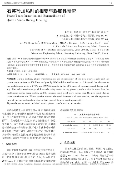
采用大林砂作为实验用砂, 砂的粒度分布见表 1, 并把一部分 石英新砂在 900 e 焙烧 75min 制 得焙烧 砂。把新 砂 和 焙烧 砂 进 行 DSC 分 析, 加 热速 度 为 20 e / min。由自制的铸造 用砂热膨胀测 定仪测定砂
- 1、下载文档前请自行甄别文档内容的完整性,平台不提供额外的编辑、内容补充、找答案等附加服务。
- 2、"仅部分预览"的文档,不可在线预览部分如存在完整性等问题,可反馈申请退款(可完整预览的文档不适用该条件!)。
- 3、如文档侵犯您的权益,请联系客服反馈,我们会尽快为您处理(人工客服工作时间:9:00-18:30)。
ZDSC-2002型自动水分测定仪是分别依据:GB/T211设计的新型智能型自动水分测定仪器,特别适用于测定煤的全水分:Mt或空气干燥煤样的水分:Mad(分析水); 广泛应用于各类实验室和化验室对固体颗粒物(包括粉状和胶体)水分含量的测定。
ZDSC-2002型用于
测定全水分。
今天我们就为大家讲解一下该仪器的特点,让更多客户了解他们的性能,这样使用起来就更加方便,简洁。
仪器特点
◎1.高度智能化、自动化;高集成、高可靠;高效率、低能耗。
◎2.选用国际知名品牌电子天平,称量迅速、数据准确。
◎3.采用大屏幕图文液晶显示器(LCD),全中文菜单式工作模式,界面友好、操作简便;毋需培训,即可上岗。
◎4.设置:微波、红外和组合三种烘干方式;恒重法和快速法两种水分测定方法;设置了全水分、分析水两个测定项目和标
准与高级两档精度以适应不同的试样要求。
设置面板式打印
机,测定结果可自动打印或手动重复打印。
◎5.内置实时时钟,自动记录实验报告时刻和日期;仪器参数和试验数据掉电不丢失;试验因突然停电中断,来电后可继续
测定。
◎6.设置自定义的加热程序,可用来进行加热或烧烤。
◎7.试样可任意放置,仪器自动判断有无容器,自动判定试样量是否在规定的范围内;一次试样摆放不满时,允许补称。
◎8.仪器自动生成当天的试样编号。
规则如下:共3位数,高两位称为“批号”:每天的第一回称样时批号是:00依次:01、
02…98、99(最大);末位数取值为:0、1、2…7、8依次对
应试样托盘上的9个放置试样的孔位。
举例:如果某试样的
编号是:100那么说明,该样是当天第10批的第0个试样位
置的那个试样。
因为试样托盘上的孔位顺序是不变的,所以,
当天所测试的每个试样对应唯一的编号。
◎9.通过大量的文字提示和声音提示各种操作信息,配合智能化
的程序流程,可实现“一键”操作,即从开机只需触按“确认”一个键就可以完成整个测试过程。
