SPB03N60C3中文资料
日本太科 PEDIII 系列控制器说明书

日本太科PEDIII 系列控制器搭配日本太科高精度电批,采用无刷直流伺服马达,实现最佳品质的螺丝拧紧。
Simple function controller for coreless DC motor tool to realize best quality screw tightening by Technart current control数字显示扭力值,通过面板按键直接设定扭力值。
针对不同的螺丝和组装工件,不同的摩擦力和材料特性,控制器会自动调节输出扭力去克服,确保螺丝拧紧的可靠性。
PEDIII适用于手持式操作的电批,也可以通过外部控制器实现简单螺丝拧紧程序运用的自动或半自动Set tightening torque value digitally.And all the rest are taken care automatically, and the torque is applied correctly and reliably, regardless of difference of screw and components, friction or joint characteristics.The PEDIII Series Controller is suitable for use with handheld manual operation type driver tool and also for auto or semi-auto application of simple screw tightening by remote control.最好的螺钉拧紧力矩控制和最简单的设定The Best Screw Tightening Torque ControlWith The Simplest SettingRoHS Complied Model Available中国总代理-深圳市瑞速科技有限公司Shenzhen Richsu Technology Co.,Ltd中国总代理-深圳市瑞速科技有限公司深圳市福田区华发北路桑达雅苑16E TEL**************/82813006FAX:0755-********E-MAIL:******************:本文档所描述的规范可随时更改,将不另行事先通知。
三品变频器主要参数

Pr078 PLC 运转方向
参数值01001010换成十进制 即:01001010B=74 所以参数Pr078=74
Pr079
PLC加减速时间
Pr079=0000000001100011B=99
内控多段速(定时器)
Pr087 Pr088 Pr089 Pr090 Pr091 Pr092 Pr093 Pr094 定时器一 定时器二 定时器三 定时器四 定时器五 定时器六 定时器七 定时器八
运行时间由 Pr087~Pr094 定时器设定,不 用的控制段,定时器设定为零即可 各段速运行方向由 Pr078 (PLC 运转方向) 设定 各段速加减速时间由 Pr079(PLC 加减速时 间)设定
Pr003-Pr007用来确定变频器的V/F曲线, 以应对不同的负载特性
Pr009 频率下限
说明: 频率下限主要防止现场人员的误操作,避 免马达因运转频率过低可能产生的过热或 其他机械故障等。 频率下限的设定必须小 于频率上限的设定值。 (频率上限即Pr007最高操作频率) 类比施耐德变频器SEt-LSP、 SEt-HSP
三品变频器主要参数说明
Pr000
主频率设定
说明: 在运转频率来源设定为面板操作情况下, 频率以 Pr000 设定值运行。 在多段速运行中,主频率为第一段速频率。 在设定为外控多段速运行时,如果把Pr034 设定为1,即外部端子给定时,则第一段速 由外部端子模拟量给定。 主频率的设定受最大操作频率限制。
类比施耐德变频器SEt-JPF、JF2
多功能输入端子设置
三品:端子——功能 施耐德:功能——端子
多功能输出端子设置
输出配置:I-O-AOIt、dO(AOV/AOC) 继电器配置:I-O-r1、r2
PCF50603资料
1.2
Supply voltage generation
• The power supplies have three programmable activity modes (OFF, ECO and ON). In the ACTIVE state, the operation modes can be selected by the two external pins PWREN1 and PWREN2. • One Charge Pump (CP) with programmable output voltage for the supply of white or blue LEDs • Two 100 mA LDO voltage regulators (RF1REG and RF2REG) with fixed output voltage (mask programmable) for RF supplies. RF1REG and RF2REG are optimized for low noise, high power supply rejection and excellent load regulation. • Two 150 mA LDO voltage regulators (D1REG and D2REG) optimized for small external capacitors. D1REG provides a programmable output voltage, D2REG provides a fixed output voltage (mask programmable). • One 150 mA LDO voltage regulator (IOREG) dedicated for the supply of the I/O pads. IOREG has a fixed output voltage (mask programmable) and is optimized for a small external capacitor. • One 100 mA LDO voltage regulator (LPREG) with fixed output voltage (mask programmable). In low power operation (ECO) mode LPREG can be used to permanently supply parts in the system in all activity states. • One 100 mA LDO voltage regulator (D3REG) with programmable output voltage. D3REG is optimized for a small external capacitor. • One 250 mA LDO voltage regulator (HCREG) with programmable output voltage. The high current HCREG is optimized for applications like hands-free audio. • D1REG, D2REG, D3REG, IOREG and LPREG support ECO mode. In this mode the output current is limited to 1 mA and the internal power consumption is reduced significantly. • The Temperature high Sensor (TS) provides பைடு நூலகம்hermal protection for the whole chip • Enhanced ESD protection on all pins that connect to the main battery pack • Microphone bias voltage generator with low noise and high power supply rejection (MBGEN).
JSCJ长晶长电开关二极管

ESD VDS VGS ID VGS(TH)RDS(mΩ)@VGS RDS(mΩ)@VGS RDS(mΩ)@VGS RDS(mΩ)@VGS Part Number Type ProcessYes/No V V A V10V Typ10V Max 4.5V Typ 4.5V Max CJAC100SN08Single-N Trench No80-1.666667100 1.0~2.5 2.9 3.9 4.3 6.2CJAB40SN10N SGT No100±2040 1.88.51311172N7000Single-N Trench No60-0.20.8~3-5000-60002N7002Single-N Trench No60±200.1151~2.59002500110030002N7002K Single-N Trench Yes60±200.341~2.59002500110030002N7002K Single-N Trench Yes60±200.341~2.59002500110030002N7002KW Single-N Trench Yes60±200.341~2.59002500110030002N7002T Single-N Trench No60±200.1151~2.59002500110030002N7002W Single-N Trench No60±200.1151~2.59002500110030002N7002X Single-N Trench No60±200.1151~2.59002500110030002SK1658Single-N Trench Yes30±70.10.9~1.5--5000100002SK3018Single-N Trench Yes30±200.10.8~1.5--500080002SK3019Single-N Trench Yes30±200.10.8~1.5--380080002SK3541Single-N Trench Yes30±200.10.8~1.5--50008000BSS123Single-N Trench No100±200.171~2.835006000380010000BSS138Single-N Trench No50±200.220.8~1.5880350015006000BSS138W Single-N Trench No50±200.220.8~1.5880350015006000CJ1012Single-N Trench Yes20±120.50.45~1.2--250700CJ2102Single-N Trench No20±8 2.10.65~1.2--5968CJ2302Single-N Trench No20±8 2.10.65~1.2--3560CJ2302S Single-N Trench No20±8 2.10.65~1.2--3560CJ2304Single-N Trench No30±20 3.31~2.237605775CJ2306Single-N Trench No30±20 3.161~338475265CJ2310Single-N Trench No60±2030.5~28210591125CJ2312Single-N Trench No20±850.45~1--1831.8CJ2324Single-N Trench No100±202 1.2~2.8195234208278CJ3134K Single-N Trench Yes20±120.750.35~1.1270380CJ3134K Single-N Trench Yes20±120.750.35~1.1--270380CJ3134KW Single-N Trench Yes20±120.750.35~1.1--260380CJ3144KW Single-N Trench Yes30±120.60.5~1.5--320500 CJ3400Single-N Trench No30±12 5.80.7~1.429353240 CJ3400A Single-N Trench No30±12 5.80.7~1.429323238 CJ3402Single-N Trench No30±1240.6~1.433553970 CJ3404Single-N Trench No30±20 5.81~323303142 CJ3406Single-N Trench No30±20 3.61~3406572105 CJ3420Single-N Trench No20±1260.5~119242227 CJ3434Single-N Trench Yes30±1050.6~132.5423544 CJ4153Single-N Trench Yes20±60.9150.45~1.1--300570 CJ8810Single-N Trench Yes20±1270.4~115.5261627 CJ8820Single-N Trench Yes20±1270.5~1.116.72118.724 CJP80N07Single-N Trench No70±25802~4 6.68--CJQ10SN15Single-N Trench No150±2010 2.0~4.03042CJAC65SN10Single-N SGT No100±20651~2.58.91112.117 CJAC70N03Single-N Trench No30±20701~2.5 4.3- 6.1-CJU60SN08Single-N Trench No80±20601~4 6.37CJQ13N04Single-N Trench No40±2013 1.2~2.59.71212.717 CJB150SN10Single-N SGT No100-1.666667150 1.2~2.5 3.4 3.7 4.76 CJB120SN08Single-N SGT No80-1.666667120 1.0~2.5 2.9 3.9 4.1 6.2 CJP120SN08Single-N SGT No80-1.666667120 1.0~2.5 3.2 3.9 4.5 6.2 2N7002KL Single-N Trench No60±200.341-3500-3200 CJAB25SN06Single-N Trench No65+20/-12V251~2.513.5162330 CJQ18SN06Single-N SGT No60±2018 1.0~2.5 5.5 6.5710 2SK3018Single-N Trench Yes30±200.10.8~1.5--50008000 CJAC150N03Single-N Trench No30±20150 1.2~2.5 1.62 2.1 2.7 CJD80SN10S Single-N SGT No100±2080 1.0~2.58.59.812.514 CJA03N10Single-N Trench No100±2031~2-140--CJU110N03Single-N Trench No30±20110 1.0~2.54 5.5610 CJB85SN08Single-N SGT No80±2085 2.0~4.0 5.5 6.8--CJB95N07Single-N Trench No65±2595 2.0~4.0 6.68--CJB92N07Single-N Trench No75±2592 2.0~4.078--CJAC90SN12Single-N SGT No120±20902~4 5.4 6.8--CJAB25N04S Single-N Trench No40±20251~2.57.59.410.515 CJL02N10Single-N Trench No100±2021~380100--CJPF130SN10Single-N SGT No100±201302~456--CJP110SN10Single-N SGT No100±201101~2.58.510--CJV01N65B Single-N Planar No650±2012~4-14000--CJBB3134K Single-N Trench No20±120.750.35~1.1--250500 CJU15N10Single-N Trench No100±20151~380100--CJU20N06Single-N Trench No60±20201~33745--CJU10N10Single-N Trench No100±209.6 1.2~2.5115140--CJU04N65Single-N Planar No650±3042~423003000--CJU02N65Single-N Planar No650±2022~438004400--CJU01N80Single-N Planar No800±3013~5-13500--CJU30N03Single-N Trench No30±20301~2.29141125 CJU30N10Single-N Trench No100±2030 1.3~2.52431--CJU40N10Single-N Trench No100±20402~41417--CJU40SN06Single-N SGT No60±2040 1.4~2.411141421 CJU4410Single-N Trench No30±207.51~3813.511.520 CJU4828Single-N Trench No60±20 4.51~337566077 CJU50N06Single-N Trench No60±2050 1.5~2.51720--CJU50SN10Single-N SGT No100±20501~2.516.522--CJU55N02Single-N Trench No20±12550.4~1.2 5.88710 CJU60N04Single-N Trench No40±2060 1.2~2.581310.520 CJU70SN10Single-N SGT No100±20701~2.59121015 CJU75N06Single-N Trench No60±20752~49.111.5--CJU80N03Single-N Trench No30±20801~3 4.5 6.5 6.310 CJU80N07Single-N Trench No65±25802~4 6.68--CJAC200SN04Single-N SGT No40±202001~30.86 1.1--CJAC140SN04Single-N SGT No40±201401~3 1.6 2.2--CJAB20SN06Single-N SGT No60±2020 1.1~2.5899.713 CJAC110N03Single-N Trench No30±20110 1.0~2.5 1.8 2.4 3.5 4.3CJAC80N03Single-N Trench No30±20801~2.5 3.1 4.2 4.57.3 CJAC75SN10Single-N SGT No100±20751~2.57.81010.116 CJAC50N06Single-N Trench No60±25502~4 5.38CJP50N06Single-N Trench No60±2050 1.5~2.51720--CJAC110SN10Single-N SGT No100±201102~445--CJAC13TH06Single-N SGT No60±201301~2.5 2.233 4.5 CJAC10TH10Single-N SGT No100±201001~2.5 5.888.510 CJAC40N04Single-N Trench No40±20401~2.57.29.51016 CJAC40N03Single-N Trench No30±20401~2.5 4.5 6.57.210.5 CJAC35N03Single-N Trench No30±20351~3 5.37812 CJAC20N10Single-N Trench No100±2020 1.3~2.526313040 CJAC20N03Single-N Trench No30±20201~38.5121218 CJM3005Single-N Trench Yes30±1050.6~132423544 CJMN2012Single-N Trench No20±10120.35~1--1015 CJM2004Single-N Trench No20±10150.5~1--67.5 CJAC10H02Single-N Trench No20±121000.5~1.2-- 1.52 CJQ12SN06Single-N SGT No60±2012 1.4~2.411141421 CJQ14SN06Single-N SGT No60±2014 1.0~2.59.71412.818 CJQ20N03Single-N Trench No30±20201~2.5 3.1 4.2 4.57.3 CJQ4406Single-N Trench No30±20101~37.8121116 CJQ4410Single-N Trench No30±207.51~3913.51220 CJQ4438Single-N Trench No60±208.21~318222536 CJP130SN10Single-N SGT No100±201302~4 4.35--CJQ08N03Single-N Trench No30±1280.5~1.513181625 CJP80N03Single-N Trench No30±20801~3 5.1 6.57.110 CJQ07N10Single-N Trench No100±207 1.2~325283038 CJP12N65Single-N Planar No650±30122~4700850--CJP10N65Single-N Planar No650±30102~47001000--CJP08N65Single-N Planar No650±3082~411001400--CJP07N65Single-N Planar No650±307.42~411001300--CJP04N65Single-N Planar No650±3042~425003000--CJP02N80Single-N Planar No800±30 2.43~5-6300--CJP02N65Single-N Planar No650±2022~438004400--CJPF12N65Single-N Planar No650±30122~4700850--CJPF10N65Single-N Planar No650±30102~47501000--CJPF08N80Single-N Planar No800±3083~511801450--CJPF08N65Single-N Planar No650±3082~412001400--CJPF07N65Single-N Planar No650±307.42~411001300--CJPF05N65Single-N Planar No650±3052~422002400--CJBA3541K Single-N Trench Yes30±120.60.8~1.5--320500 CJPF04N80Single-N Planar No800±3043~521003000--CJPF04N65Single-N Planar No650±3042~425003000--CJPF03N80Single-N Planar No800±3033~4.532004200--CJPF02N65Single-N Planar No650±2022~438004400--CJBA7002K Single-N Trench Yes60±200.41 1.3~2.31200150013001800 CJD04N65Single-N Planar No650±3042~423003000--CJD02N65Single-N Planar No650±2022~438004400--CJB130SN10Single-N SGT No100±201302~4 4.35--CJB110SN10Single-N SGT No100±20110 1.0~2.58.5109.514 CJB40N20Single-N Trench No200±2040 2.0~4.036.441--CJBA3134K Single-N Trench Yes20±120.750.35~1.1--250500 CJAA3134K Single-N Trench Yes20±120.750.35~1.1---380 CJW1012Single-N Trench Yes20±120.50.45~1.2--250700 CJAB40SN10Single-N SGT No100±2040 1.4~2.59131217 CJAB60N03Single-N Trench No30±20601~2.5 2.9 4.2 4.27.3 CJAB55N03Single-N Trench No30±20551~2.5 3.6 5.5 5.99.5 CJAB40N03Single-N Trench No30±20401~2.5 4.5 6.57.210.5 CJAB25N04Single-N Trench No40±20251~2.57.29.51016 CJAB35N03Single-N Trench No30±20351~3 5.37812 CJAB25N03Single-N Trench No30±20251~3 5.5101014 CJAB20N07Single-N Trench No20±10300.4~1.5-- 6.37 CJAB20N03Single-N Trench No30±20201~38.5121218CJE3134K Single-N Trench Yes20±120.750.35~1.1--260380 CJT04N15Single-N Trench No150±204 1.5~2.5130160--CJA03N10S Single-N Trench No100±2031~3113140--CJA9452Single-N Trench No20±1240.6~1.518382050 CJK8804Single-N Trench Yes20±1270.5~19.81310.514 CJK3400AH Single-N Trench No30±12 5.80.7~1.419272032 CJK3400A Single-N Trench No30±12 5.80.7~1.429323238 CJK1508Single-N Trench Yes15±1280.5~17.79.58.610.5PackagePDFNWB5×6-8L PDFNWB3.3×3.3-8L TO-92SOT-23TO-92SOT-23SOT-323SOT-523SOT-323SOT-89-3LSOT-323SOT-323SOT-523SOT-723SOT-23SOT-23SOT-323SOT-523SOT-323SOT-23SOT-23SOT-23SOT-23SOT-23SOT-23SOT-23SOT-23SOT-723SOT-323SOT-323SOT-23SOT-23SOT-23SOT-23SOT-23SOT-23SOT-23SOT-523SOT-23SOT-23TO-220-3L-CSOP8PDFNWB5x6-8L-D PDFNWB5x6-8L-D TO-252-2LSOP8TO-263-2LTO-263-2LTO-220-3L-CSOT-23PDFNWB3.3×3.3-8L SOP8SOT-23PDFNWB5×6-8LTO-251SSOT-89-3LTO-252-2LTO-263-2LTO-263-2LTO-263-2LPDFNWB5×6-8L PDFNWB3.3x3.3-8L SOT-23-6LTO-220FTO-220-3LTO-92DFN1006-3L-ATO-252-2LTO-252-2LTO-252-2LTO-252-2LTO-252-2LTO-252-2LTO-252-2LTO-252-2LTO-252-2LTO-252-2LTO-252-2LTO-252-2LTO-252-2LTO-252-2LTO-252-2LTO-252-2LTO-252-2LTO-252-2LTO-252-2LTO-252-2L PDFNWB5x6-8L-C PDFNWB5x6-8L-C DFNWB3×3-8L PDFNWB5×6-8LPDFNWB5×6-8L PDFNWB5×6-8L PDFNWB5×6-8L TO-220-3L-C PQFNWB5×6-8L PQFNWB5×6-8L PQFNWB5×6-8L PDFNWB5×6-8L PDFNWB5×6-8L PDFNWB5×6-8L PDFNWB5×6-8L PDFNWB5×6-8L DFNWB2×2-6L-J DFNWB2×2-6L-J DFNWB2×2-6L-J PDFNWB5×6-8L SOP8SOP8SOP8SOP8SOP8SOP8TO-220-3L-C SOP8TO-220-3L-C SOP8TO-220-3LTO-220-3LTO-220-3LTO-220-3LTO-220-3LTO-220-3LTO-220-3LTO-220FTO-220FTO-220FTO-220FTO-220FTO-220FDFN1006-3LTO-220FTO-220FTO-220FTO-220FDFN1006-3LTO-251STO-251STO-263-2LTO-263-2LTO-263-2LDFN1006-3L WBFBP-03ESOT-323 PDFNWB3.3x3.3-8L PDFNWB3.3x3.3-8L PDFNWB3.3x3.3-8L PDFNWB3.3x3.3-8L PDFNWB3.3x3.3-8L PDFNWB3.3x3.3-8L PDFNWB3.3x3.3-8L PDFNWB3.3x3.3-8L PDFNWB3.3x3.3-8LSOT-523 SOT-223 SOT-89-3L SOT-89-3L SOT-23-3L SOT-23-3L SOT-23-3L SOT-23-3L。
美国电缆工业Eaton公司Moeller系列PKZM0三极保护断路器说明书

Eaton 265330Eaton Moeller® series PKZM0 Motor-protective circuit-breaker, 3p, Ir=0.1-0.16A, thumb grip lockableGeneral specificationsEaton Moeller® series PKZM0 Motor-protective circuit-breaker265330PKZM0-0,16/AK401508265330976 mm 93 mm 45 mm 0.25 kgCSA-C22.2 No. 60947-4-1-14 CSA Class No.: 3211-05 UL 60947-4-1 CSAIEC/EN 60947 IEC/EN 60947-4-1 ULCSA File No.: 165628UL Category Control No.: NLRV CEUL File No.: E36332 VDE 0660Product NameCatalog Number Model Code EANProduct Length/Depth Product Height Product Width Product Weight CertificationsTurn buttonPhase-failure sensitivity (according to IEC/EN 60947-4-1, VDE 0660 Part 102)Motor protectionPhase failure sensitiveThree-pole ATEX dust-ex-protection, PTB 10, ATEX 3013, Ex II(2) GD100,000 operations (at 400V, AC-3)100,000 Operations (Main conducting paths)Can be snapped on to IEC/EN 60715 top-hat rail with 7.5 or15 mm height.40 Operations/hIII3Motor protective circuit breakerFinger and back-of-hand proof, Protection against direct contact when actuated from front (EN 50274)6000 V AC25 g, Mechanical, according to IEC/EN 60068-2-27, Half-sinusoidal shock 10 msAlso motors with efficiency class IE3Branch circuit: Manual type E if used with terminal, or suitable for group installations, (UL/CSA)-25 - 55 °C, Operating range≤ 0.25 %/K, residual error for T > 40°-5 - 40 °C to IEC/EN 60947, VDE 0660Actuator type Features Functions Number of poles Explosion safety category for dust Lifespan, electricalLifespan, mechanicalMounting positionOperating frequencyOvervoltage categoryPollution degreeProduct categoryProtectionRated impulse withstand voltage (Uimp) Shock resistanceSuitable forTemperature compensationAltitude Terminal capacity (flexible with ferrule)Max. 2000 m-25 °C55 °C25 °C40 °C40 °C80 °CDamp heat, cyclic, to IEC 60068-2-30 Damp heat, constant, to IEC 60068-2-781 x (1 - 6) mm², ferrule to DIN 462282 x (1 - 6) mm², ferrule to DIN 462281 x (1 - 6) mm²2 x (1 - 6) mm²18 - 1010 mm1 Nm, Screw terminals, Control circuit cables 1.7 Nm, Screw terminals, Main cable50 Hz60 Hz0.16 A0 kW0 kW690 V690 V0.16 A60 kA DC, up to 250 V DC, Main conducting paths50 kA, 600 V High Fault, Fuse, SCCR (UL/CSA)600 A, 600 V High Fault, max. Fuse, SCCR (UL/CSA) Screw terminalsAmbient operating temperature - minAmbient operating temperature - maxAmbient operating temperature (enclosed) - min Ambient operating temperature (enclosed) - max Ambient storage temperature - minAmbient storage temperature - maxClimatic proofing Terminal capacity (solid)Terminal capacity (solid/stranded AWG)Stripping length (main cable)Tightening torqueRated frequency - minRated frequency - maxRated operational current (Ie)Rated operational power at AC-3, 220/230 V, 50 Hz Rated operational power at AC-3, 380/400 V, 50 Hz Rated operational voltage (Ue) - minRated operational voltage (Ue) - maxRated uninterrupted current (Iu)Short-circuit currentShort-circuit current rating (group protection)Connection50 kA, 600 V High Fault, CB, SCCR (UL/CSA)600 A, 600 V High Fault, max. CB, SCCR (UL/CSA)Accessories required BK25/3-PKZ0-E65 kA, 240 V, SCCR (UL/CSA)65 kA, 480 Y/277 V, SCCR (UL/CSA)50 kA, 600 Y/347 V, SCCR (UL/CSA)Basic device fixed 15.5 x Iu, Trip Blocks2.5 A, Irm, Setting range max.± 20% tolerance, Trip blocks 0.1 A0.16 AOverload trigger: tripping class 10 A5.39 W0 W1.8 W0.16 A0 WMeets the product standard's requirements.Meets the product standard's requirements.Meets the product standard's requirements.Meets the product standard's requirements.Meets the product standard's requirements.Does not apply, since the entire switchgear needs to be evaluated.Does not apply, since the entire switchgear needs to be evaluated.Meets the product standard's requirements.Short-circuit current rating (type E) Short-circuit release Overload release current setting - minOverload release current setting - maxTripping characteristicEquipment heat dissipation, current-dependent PvidHeat dissipation capacity PdissHeat dissipation per pole, current-dependent PvidRated operational current for specified heat dissipation (In) Static heat dissipation, non-current-dependent Pvs10.2.2 Corrosion resistance10.2.3.1 Verification of thermal stability of enclosures10.2.3.2 Verification of resistance of insulating materials to normal heat10.2.3.3 Resist. of insul. mat. to abnormal heat/fire by internal elect. effects10.2.4 Resistance to ultra-violet (UV) radiation10.2.5 Lifting10.2.6 Mechanical impact10.2.7 InscriptionsDoes not apply, since the entire switchgear needs to be evaluated.Meets the product standard's requirements.Does not apply, since the entire switchgear needs to be evaluated.Does not apply, since the entire switchgear needs to be evaluated.Is the panel builder's responsibility.Is the panel builder's responsibility.Is the panel builder's responsibility.Is the panel builder's responsibility.Is the panel builder's responsibility.The panel builder is responsible for the temperature rise calculation. Eaton will provide heat dissipation data for the devices.Is the panel builder's responsibility. The specifications for the switchgear must be observed.Is the panel builder's responsibility. The specifications for the switchgear must be observed.The device meets the requirements, provided the information in the instruction leaflet (IL) is observed.Motor Starters in System xStart - brochureSave time and space thanks to the new link module PKZM0-XDM32MESwitching and protecting motors - catalogProduct Range Catalog Switching and protecting motorseaton-manual-motor-starters-characteristic-characteristic-curve.eps eaton-manual-motor-starters-characteristic-characteristic-curve-009.eps eaton-manual-motor-starters-characteristic-characteristic-curve-008.epsDA-DC-00004892.pdfDA-DC-00004921.pdfeaton-manual-motor-starters-pkz-dimensions-002.epseaton-manual-motor-starters-pkz-dimensions.epseaton-manual-motor-starters-mounting-3d-drawing-002.epseaton-general-ie-ready-dilm-contactor-standards.epseaton-manual-motor-starters-pkzm0-3d-drawing-008.epseaton-manual-motor-starters-pkzm0-3d-drawing.epsDA-CE-ETN.PKZM0-0,16_AKIL03402034ZIL03407010ZWIN-WIN with push-in technologyIL122023ZUeaton-motor-protective-circuit-breaker-pkzm0-overload-monitoring-exe-manual-mn03402003z-de-de-en-us.pdfDA-CD-pkzm0_ak_neu_aDA-CS-pkzm0_ak_neu_aeaton-manual-motor-starters-transformer-pkzm0-wiring-diagram.eps10.3 Degree of protection of assemblies10.4 Clearances and creepage distances10.5 Protection against electric shock10.6 Incorporation of switching devices and components 10.7 Internal electrical circuits and connections10.8 Connections for external conductors10.9.2 Power-frequency electric strength10.9.3 Impulse withstand voltage10.9.4 Testing of enclosures made of insulating material 10.10 Temperature rise10.11 Short-circuit rating10.12 Electromagnetic compatibility10.13 Mechanical function BrochuresCatalogues Characteristic curve Declarations of conformity DrawingseCAD modelInstallation instructions Installation videos Manuals and user guides mCAD modelWiring diagramsEaton Corporation plc Eaton House30 Pembroke Road Dublin 4, Ireland © 2023 Eaton. All rights reserved. Eaton is a registered trademark.All other trademarks areproperty of their respectiveowners./socialmedia。
西門子PRC-CM03無熔絲開關說明書说明书
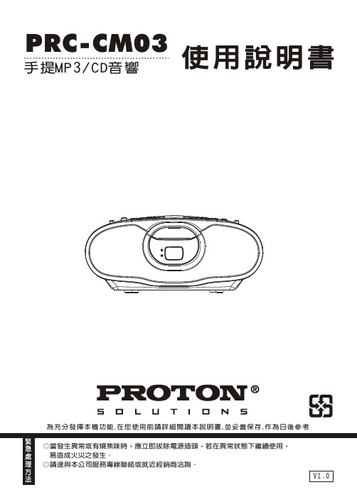
使用說明書PRC-CM03為充分發揮本機功能,在您使用前請詳細閱讀本說明書,並妥善保存,作為日後參考手提MP3/CD音響目錄(一)本機特點及緊急處理方法&警告 (2)(二)安全注意事項 (3)(三)免責聲明 (3)(四)外型及各部位名稱 (4)(五)安裝方法 (5)(六)規格 (5)(七)功能操作 (6)功能選擇 (6)音量調整 (6)調諧電台 (6)CD/MP3唱片的使用 (7)CD/MP3唱片的播放 (7)搜尋特定樂曲 (7)搜尋特定歌曲片段 (8)重複播放 (8)低音加強功能 (8)程序播放記憶 (9)外部音源功能 (9)耳機使用 (9)(八)保養 (10)(九)故障排除 (10)1˙HI/FI立體聲˙具播放CD/MP3/收音機功能˙AM(MONO)/FM立體聲收音˙具有耳機插孔˙CD 20首及MP3 99首曲目編輯播放功能。
˙具重複播放、資料夾重複播放、單曲重複播放及隨機播放功能˙具外部音源輸入擴音功能˙具低音加強功能2在使用本機之前,應仔細閱讀下列事項及使用說明,閱後並請妥為收存,以備將來參考:1.本機請勿置於雨中、濕氣中或避免陽光直射及遠離其他會產生熱能的裝置。
2.本機放置位置請勿太靠近電視、電腦、錄影機及手機,以免遭受干擾,產生誤 動作。
003.使用本機的工作溫度為5~35C。
4.長期不使用本機時,應將其電源線插頭從插座內拔出。
5.請勿將雜物或液體從機身開口處進入機身內部。
6.當本機出現下列情況時,應請合格的維修人員進行維修:A:故障或液體落入本機內。
B:雜物或液體落入本機內。
C:受到雨淋。
D:無法正常操作或性能出現明顯變化。
E:不慎跌落或外殼受損。
7.請勿擅自拆下任何蓋子、內部裝置或調校內部裝置,請交由本公司專業人員進 行維修。
8.使用耳機時,請勿將音量調太大聲,以免聽力受損。
9.當耳朵產生耳鳴時,應將音量調小或取消耳機使用。
10.當使用開放式耳機時,請勿將音量調太大聲,以避免聽不到周遭的聲音。
PSD03_03中文资料

PSD03thruPSD24CST ANDARD CAP ACIT ANCE TVS ARRA YOnly One Name Means ProTek’Tion™APPLICA TIONS✔ Laptop Computers✔ Cellular Phones ✔ Digital Cameras✔ Personnal Digital Assistant (PDA)IEC COMP A TIBILITY (EN61000-4)✔ 61000-4-2 (ESD): Air - 15kV , Contact - 8kV ✔ 61000-4-4 (EFT): 40A - 5/50ns✔ 61000-4-5 (Surge): 24A, 8/20µs - Level 2(Line-Ground) & Level 3(Line-Line)FEA TURES✔ Unidirectional: 500 Watts Peak Pulse Power per Line (tp = 8/20µs)✔ BidirectionalL 400 Watts Peak Pulse Power per Line (tp = 8/20µs)✔ Unidirectional & Bidirectional Configurations ✔ Replacement for MLV (0805)✔ Protects One Power or I/O Port ✔ ESD Protection > 40 kilovolts ✔ Low Clamping Voltage✔ Available in Multiple Voltage Types Ranging from 3V to 24V MECHANICAL CHARACTERISTICS✔ Molded JEDEC SOD-323✔ Weight 10 milligrams (Approximate)✔ Flammability Rating UL 94V-0✔ 8mm Tape and Reel Per EIA Standard 481✔ Device Marking: Marking Code & Polarity Band (Unidirectional Only)05118PIN CONFIGURA TIONSSOD-323UNIDIRECTIONALBIDIRECTIONALPSD24CDEVICE CHARACTERISTICSMAXIMUM RATINGS @ 25°C Unless Otherwise SpecifiedUndirectional: Peak Pulse Power (t p = 8/20µs) - See Fig. 1Operating T emperature SYMBOL VALUE -55°C to 150°C°C°C -55°C to 150°C Watts UNITS 500T J P PP T STGPARAMETERStorage T emperatureBidirectional: Peak Pulse Power (t p = 8/20µs) - See Fig. 1Watts 400P PP Note 1: Part numbers with an additional “C” suffix are bidirectional devices, i.e., PSD05C.Note 2: For Bidirectional Devices Only: Electrical characteristics apply in both directions.ELECTRICAL CHARACTERISTICS PER LINE @ 25°C Unless Otherwise SpecifiedPART NUMBER (See Notes 1-2)DEVICE MARKINGMINIMUM BREAKDOWN VOLTAGE@ 1mA V (BR)VOLTS MAXIMUM CLAMPING VOLTAGE (See Fig. 2)@ I P = 1AV C VOLTS MAXIMUM CLAMPING VOLTAGE (See Fig. 2)@8/20µs V C @ I PP TYPICAL CAPACITANCE@0V , 1 MHzC J pFPSD03PSD03C PSD05PSD05C PSD08PSD08C PSD12PSD12C PSD15PSD15C PSD18PSD18C PSD24PSD24C PSD36PSD36CA GB HC JD KE L G NF M R T4.04.06.06.08.58.513.313.316.716.720.020.026.726.740.040.06.57.09.89.813.413.419.019.024.024.029.029.043.043.060.060.010.9V @ 43.0A 10.9V @ 39.0A 13.5V @ 42.0A 14.5V @ 28.0A 16.9V @ 34.0A 18.5V @ 17.0A 25.9V @ 21.0A 29.5V @ 14.0A 30.0V @ 17.0A 33.0V @ 12.0A 40.0V @ 9.0A 40.0V @ 9.0A 49.0V @ 12.0A 46.2V @ 9.0A 75.0V @ 5.0A 75.0V @ 5.0A5002003501752501501505010040904088407535MAXIMUM LEAKAGE CURRENT@V WMI D µA 125125101010101111111111RATED ST AND-OFF VOLTAGEV WM VOLTS3.33.35.05.08.08.012.012.015.015.018.018.024.024.036.036.0PSD24CFIGU RE 50 1 2 3 4 5 6V R - Reverse Voltage - VoltsC - C a p a c i t a n c e - p F100200300400FIGU RE 2FIGU RE 1PEAK PULSE POWER VS PULSE TIME0.01 1 10 100 1,000 10,000t d - Pulse Duration - µs0 5 10 15 20 25 30t - Time - µs20406080100120I P P - P e a kP u l s e C u r r e n t - % o f I P P101001,00010,000P P P - P e ak P u l s e C u r r e n t - W a t t sGRAPHSFIGU RE 4OVERSHOOT & CLAMPING VOLTAGE FOR PSD03ESD Test Pulse: 25 kilovolt, 1/30ns (waveform)5 V o l t s p e r D i v i s i o n-55152535T L - Lead Temperature - °C20406080100% O f R a t e d P o w e rFIGU RE 3PSD24CCOPYRIGHT © ProTek Devices 2003SPECIFICATIONS: ProT ek reserves the right to change the electrical and or mechanical characteristics described herein without notice (except JEDEC).DESIGN CHANGES: ProT ek reserves the right to discontinue product lines without notice, and that the final judgement concerning selection and specifications is the buyer’s and that in furnishing engineering and technical assistance, ProTek assumes no responsibility with respect to the selection or specifications of such products.P ACKAGE OUTLINE & DIMENSIONSProTek Devices2929 South Fair Lane, Tempe, AZ 85282Tel: 602-431-8101 Fax: 602-431-2288E-Mail: sales@ Web Site: 。
SC3说明书
注意安全事项 请合格的专业人员进行安装、操作、维护检查。 在本说明书中,将安全注意事项等级分为“警告”和“注意”。
警告:不正确操作会造成危险情况,将导致死亡或重伤的发生。 注意:不正确操作会造成危险情况,将导致一般或轻微伤害或物体损坏。
注意 各个端子上加的电压只能是操作手册上规定的电压。否则会造成故障或损坏。 请勿对变频器内部的零组件进行耐压测试,因变频器所使用的半导体易受高压击穿而损坏。 通电中或断开电源不久,因为变频器温度较高,仅可触摸操作器。否则会引起烫伤。 请勿错误连接端子。否则会造成故障或损坏。 不要将极性(+、-)搞错。否则会造成故障或损坏。 变频器请安装在无孔的不可燃的壁面上(避免从背后触及变频器散热片)。直接安装在易燃物上或靠近易燃物品,会 导致火灾。 变频器发生故障时,请断开变频器的电源。若持续地流过大电流,会导致火灾。
士林通用变频器 SC3 系列
操作手册
高性价比
SC3-021-0.2K~2.2K SC3-023-0.2K~3.7K SC3-043-0.4K~5.5K
操作手册导读Байду номын сангаас1 交货检查 2
变频器介绍 3 基本操作 4 参数说明 5
检查与维护 6 附录 7
安全注意事项
1. 操作手册导读
1.1 安全注意事项
警告
变频器通电中不可打开其前盖板和接线板。并且不可在前盖板和接线板卸下的状态下运行变频器。否则可能会接触到 高电压的端子和充电部分而造成触电事故。 若要改变接线或检查,首先应关掉变频器的电源。在变频器七段码显示器未熄灭前,表示变频器内部仍有高压,请勿 触摸内部电路及零组件。 本变频器必须正确接地。 请不要用湿手操作、触碰散热器、插拔线缆,否则会导致触电。 请勿在通电时进行冷却风扇的更换,否则会发生危险。通电中进行冷却风扇的交换是危险的
NCP603中文资料

2
元器件交易网
NCP603
ELECTRICAL CHARACTERISTICS (Vin = 1.750 V, Vout = 1.250 V, Cin = Cout =1.0 mF, for typical values TA = 25°C, for min/max
Typical Applications
•ăSMPS Post-Regulation •ăHand-held Instrumentation & Audio Players •ăNoise Sensitive Circuits – VCO, RF Stages, etc. •ăCamcorders and Cameras •ăPortable Computing
ESD Human Body Model tested per AEC-Q100-002 (EIA/JESD22-A114) ESD Machine Model tested per AEC-Q100-003 (EIA/JESD22-A115) Latchup Current Maximum Rating: v150 mA per JEDEC standard: JESD78.
-
62 55 38
-
Line Regulation
Load Regulation Output Noise Voltage (Note 9) Output Short Circuit Current Dropout Voltage
1.25 V
Dropout Voltage 1.25 V
Regline
THERMAL CHARACTERISTICS
Rating
Thermal Characteristics, TSOP-5 (Note 4) Thermal Resistance, Junction-to-Air (Note 5)
SPI20N60C3中文资料

VDD=380V, VGS=0/13V, ID=20.7A, RG=3.6Ω, Tj=125 VDD=380V, VGS=0/13V, ID=20.7A, RG=3.6Ω
Values
Unit
min. typ. max.
- 17.5 - S
- 2400 - pF
0.00769 K/W Cth1
0.015
Cth2
0.029
Cth3
0.163
Cth4
0.323
Cth5
2.526
Cth6
Value
Unit
SPP_B_I
SPA
0.0003763 0.0003763 Ws/K
0.001411 0.001411
0.001931 0.001931
0.005297 0.005297
Marking 20N60C3 20N60C3 20N60C3 20N60C3
Maximum Ratings Parameter
Continuous drain current
TC = 25 °C TC = 100 °C
Pulsed drain current, tp limited by Tjmax Avalanche energy, single pulse
- 700
breakdown voltage
-V -
Gate threshold voltage Zero gate voltage drain current
VGS(th) I DSS
ID=1000µA, VGS=VDS 2.1
VDS=600V, VGS=0V,
Tj=25°C
西门子CC工控

通讯产品 ................................................................................................................................. 3/229
AS-interface ................................................................................................................................. 3/229 ET200 电机起动器 ........................................................................................................................ 3/235 SIMOCODE.................................................................................................................................. 3/237
SIRIUS 继电器产品.......................................................................................................... 3/223
热敏电阻电机保护继电器 3RN ....................................................................... 3/223
24N60C3中文资料
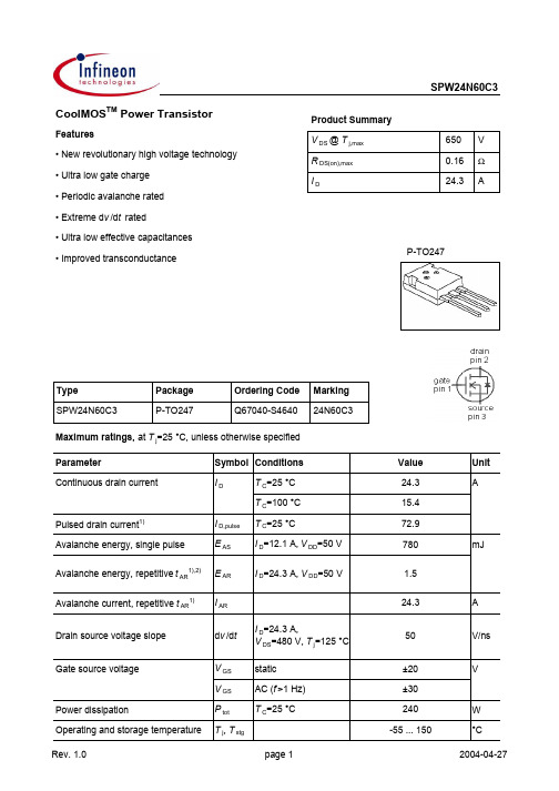
SPW24N60C3Parameter Symbol Conditions Unitmin.typ.max. Thermal characteristicsThermal resistance, junction - case R thJC--0.52K/WR thJA leaded--62Soldering temperature T sold 1.6 mm (0.063 in.)from case for 10 s--260°CElectrical characteristics, at T j=25 °C, unless otherwise specifiedStatic characteristicsDrain-source breakdown voltage V(BR)DSS V GS=0 V, I D=250 µA600--V Avalanche breakdown voltage V(BR)DS V GS=0 V, I D=24.3 A-700-Gate threshold voltage V GS(th)V DS=V GS, I D=1.2 mA 2.13 3.9Zero gate voltage drain current I DSS V DS=600 V, V GS=0 V,T j=25 °C-0.11µAV DS=600 V, V GS=0 V,T j=150 °C--100Gate-source leakage current I GSS V GS=20 V, V DS=0 V--100nADrain-source on-state resistance R DS(on)V GS=10 V, I D=15.4 A,T j=25 °C-0.140.16ΩV GS=10 V, I D=15.4 A,T j=150 °C-0.34-Gate resistance R G f=1 MHz, open drain-0.7-Transconductance g fs |V DS|>2|I D|R DS(on)max,I D=15.4 A-24-SValuesThermal resistance, junction - ambientSPW24N60C3Parameter Symbol Conditions Unitmin.typ.max. Dynamic characteristicsInput capacitance C iss-2800-pF Output capacitance C oss-930-Reverse transfer capacitance C rss-66-Effective output capacitance, energyrelated3)C o(er)-114-Effective output capacitance, timerelated4)C o(tr)-204-Turn-on delay time t d(on)-13-ns Rise time t r-21-Turn-off delay time t d(off)-73-Fall time t f-6-Gate Charge CharacteristicsGate to source charge Q gs-15-nC Gate to drain charge Q gd-49-Gate charge total Q g-105137Gate plateau voltage V plateau- 5.4-V4)Co(tr) is a fixed capacitance that gives the same charging time as C oss while V DS is rising from 0 to 80% V DSS.ValuesV GS=0 V, V DS=25 V,f=1 MHzV DD=480 V,V GS=10 V, I D=24.3 A,R G=3.3 ΩV DD=480 V,I D=24.3 A,V GS=0 to 10 VV GS=0 V, V DS=0 Vto 480 V1) Pulse width limited by maximum temperature Tj,maxonly2) Repetitive avalanche causes additional power losses that can be calculated as PAV=E AR*f.3)Co(er)is a fixed capacitance that gives the same stored energy as C oss while V DS is rising from 0 to 80% V DSS.SPW24N60C3 Definition of diode switching characteristicsP-TO247: OutlineDimensions in mmSPW24N60C3 Published byInfineon Technologies AGBereich KommunikationSt.-Martin-Straße 53D-81541 München© Infineon Technologies AG 1999All Rights Reserved.Attention please!The information herein is given to describe certain components and shall not be considered aswarranted characteristics.Terms of delivery and rights to technical change reserved.We hereby disclaim any and all warranties, including but not limited to warranties of non-infringement, regarding circuits, descriptions and charts stated herein.Infineon Technologies is an approved CECC manufacturer.InformationFor further information on technology, delivery terms and conditions and prices, please contact your nearest Infineon Technologies office in Germany or our Infineon Technologies representatives worldwide (see address list).WarningsDue to technical requirements, components may contain dangerous substances.For information on the types in question, please contact your nearest Infineon Technologies office. Infineon Technologies' components may only be used in life-support devices or systems with the expressed written approval of Infineon Technologies if a failure of such components can reasonablybe expected to cause the failure of that life-support device or system, or to affect the safety or effectiveness of that device or system. Life support devices or systems are intended to be implantedin the human body, or to support and/or maintain and sustain and/or protect human life. If they fail,it is reasonable to assume that the health of the user or other persons may be endangered.。
SPB-3全自动空气源说明书

2
2、仪器的自检:
a. 拧紧仪器背面空气出口上的密封螺帽,接通电源,打开 电源开关。此时开关上红色指示灯亮,压力表指针在5 分钟内由0上升到0.4MPa一段时间后压缩机停止工作。
b. 关 闭 电 源 开 关,若 10 分 钟 内 压 力 表 的 压 力 仍 保 持 在 0.4MPa, 表明仪器正常,自检合格。
⑤ ⑥ ⑦ ⑧
仪器背面图
1、过滤器 4、电源开关 7、限流调节
2、压力表 5、空气出口 8、电源线
3、稳压阀 6、自动放水口
四、仪器的安装与使用
1、开箱检查:
a. 将仪器从包装箱内取出,核对合格证、保修卡、仪器备 件是否齐全。
b. 检查仪器外观,观察仪器有无在运输中造成损坏。若发 现异常,请立即与我公司联系解决。
我 们 坚 持 质 量 第 一,用 户 至 上 的 服 务 准 则,产 品 遍 及 全 国,并出口挪威、阿根廷、韩国、乌克兰等18个国家和地区。
二、产品概述
SPB-3(GCK3302)型全自动空气源,是一种为气相色谱仪专 用的压力稳定,纯净的空气源。可满足任何厂家生产的任何型 号的气相色谱仪使用,是替代高压空气瓶供气的一种理想的升 级换代产品。产品通过国家分析仪器监督检验中心检测。
c. 寿 命 长:储气罐的出口处设有压力控制器。当储气罐中 的压力降至下限到0.6MPa时压力控制器开始动作,当储 气罐中的压力达到上限0.8MPa时压力控制器关闭电源, 压缩机停止工作,周而复始满足系统工作的需要。当系 统超压时有安全保护系统。系统中设有低压启动装置, 保证每次主机启动时气压为零,大大提高了主机的使用 寿命。
BCHP
全自动空气源
SPB-3/GCK3302
使 用 说 明 书
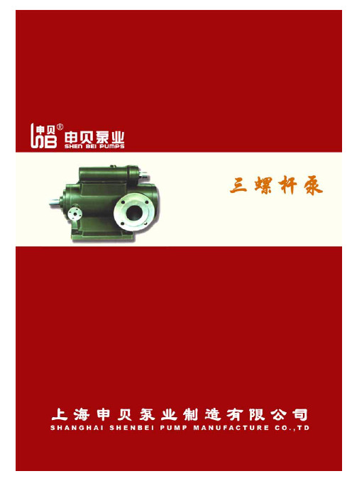
三螺杆泵产品样本(申贝泵业)
410
Y132S
485
45x3-46
210
485
800
380
340
340
217
Y132M
525
45x2-52
Y160M
610
255
580
925
430
300
390
245
Y160L
655
10
3GFBW45,3GF45 型 法兰式泵外形及安装尺寸
三螺杆泵样本资料
泵规 机座
外形安装尺寸(mm)
格
号
AD L L1 L2 L3 L4 L5 L6 B B1 B2 H D1 D2 D3 D4 D5 D6
34 370 260 220 160 308
Y90S 155 260
30x4-40 Y90L
105 140 73 285
33 400 220 185 120 267
30x4-46
30x3-52 Y100L 180 320
154
30x2-54 Y112M 190 30x3-54
340
110
150
75
34 407 260 220 160 308
Y90S
270
155
105 148
Y9Байду номын сангаасL
295
23.5 425
45x4-27 Y100L 180 325
280 235 120 160 ¢50 ¢110 ¢140 ¢40 ¢110 ¢150
115 158 114 115 24 436 Y112M 190 340 45x2-36
三螺杆泵样本资料
泵规格 机座号
外形安装尺寸(mm)
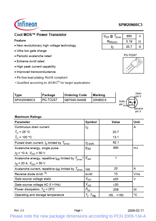
英飞凌SPW20N60C3_Rev.2.5_PCN规格书
6ROGHULQJWHPSHUDWXUHwavesoldering PP LQ IURPFDVHIRUV
7VROG
&
(OHFWULFDO&KDUDFWHULVWLFV DW7M &XQOHVVRWKHUZLVHVSHFLILHG 3DUDPHWHU 6\PERO &RQGLWLRQV PLQ 'UDLQVRXUFHEUHDNGRZQYROWDJH V(BR)DSS VGS 9,' P$ 'UDLQ6RXUFHDYDODQFKH EUHDNGRZQYROWDJH *DWHWKUHVKROGYROWDJH =HURJDWHYROWDJHGUDLQFXUUHQW 9*6 WK ,'66
Turn-on delay time
V GS 9 V DS 9WR9
S)
td(on)
V DD 9V GS 9 ,' $R G Ω Tj
QV
Rise time Turn-off delay time Fall time
*DWH&KDUJH&KDUDFWHULVWLFV Gate to source charge Gate to drain charge *DWHFKDUJHWRWDO *DWHSODWHDXYROWDJH
$ 9QV 9 : &
*DWHVRXUFHYROWDJH$& I!+] 3RZHUGLVVLSDWLRQ7 & & 2SHUDWLQJDQGVWRUDJHWHPSHUDWXUH
VGS Ptot 7 M7 VWJ
Rev. 2.5
6\PERO GYGW
inspiron 3646 3000 series 用户手册说明书

Inspiron 3646 3000 Series用户手册计算机型号: Inspiron 3646管制型号: D10S管制类型: D10S001注、小心和警告注: “注”表示可以帮助您更好地使用计算机的重要信息。
小心: “小心”表示可能会损坏硬件或导致数据丢失,并说明如何避免此类问题。
警告: “警告”表示可能会造成财产损失、人身伤害甚至死亡。
版权所有© 2014 Dell Inc. 保留所有权利。
本产品受美国、国际版权和知识产权法律保护。
Dell™和 Dell 徽标是 Dell Inc. 在美国和 / 或其他管辖区域的商标。
所有此处提及的其他商标和产品名称可能是其各自所属公司的商标。
2014 - 05Rev. A00目录拆装计算机内部组件之前 (7)开始之前 (7)安全说明 (7)建议工具 (8)拆装计算机内部组件之后 (9)技术概览 (10)计算机内部视图 (10)系统板组件 (11)卸下主机盖 (12)步骤 (12)装回主机盖 (13)步骤 (13)卸下内存模块 (14)前提条件 (14)步骤 (14)装回内存模块 (16)步骤 (17)完成条件 (17)卸下风扇 (18)前提条件 (18)步骤 (18)装回风扇 (20)步骤 (20)完成条件 (21)卸下前挡板 (22)前提条件 (22)步骤 (23)装回前挡板 (25)步骤 (25)完成条件 (25)卸下驱动器固定框架 (26)前提条件 (26)步骤 (26)装回驱动器固定框架 (28)步骤 (28)完成条件 (28)卸下无线网卡 (29)前提条件 (29)步骤 (29)装回无线网卡 (31)步骤 (31)完成条件 (31)卸下光盘驱动器 (32)前提条件 (32)步骤 (32)装回光盘驱动器 (33)步骤 (33)完成条件 (33)卸下硬盘驱动器 (34)前提条件 (34)步骤 (34)装回硬盘驱动器 (35)步骤 (35)完成条件 (35)卸下前 I/O 面板 (36)前提条件 (36)步骤 (36)装回前 I/O 面板 (38)步骤 (38)完成条件 (38)卸下电源按钮模块 (39)前提条件 (39)步骤 (39)装回电源按钮模块 (41)步骤 (41)完成条件 (41)取出币形电池 (42)前提条件 (42)步骤 (43)装回币形电池 (44)步骤 (44)完成条件 (44)卸下系统板 (45)前提条件 (45)步骤 (45)装回系统板 (47)步骤 (47)完成条件 (47)系统设置程序 (48)概览 (48)进入系统设置 (48)清除已忘记的密码 (48)前提条件 (49)步骤 (49)完成条件 (49)清除 CMOS 设置 (50)前提条件 (50)步骤 (50)完成条件 (51)刷新 BIOS (52)获取帮助和联系 Dell (53)自助资源 (53)联系 Dell (53)拆装计算机内部组件之前小心: 持拿组件和插卡时,请持拿其边缘,切勿触碰插针和接点,以避免损坏。
EN61000-3-3中文版

EN61000-3-3中文版奥地利,比利时,丹麦,芬兰,法国,德国,希腊,冰岛,爱尔兰,意大利,卢森堡,荷兰,挪威,葡萄牙,西班牙,瑞典,瑞士和联合王国(英国)。
1、围IEC 61000-3 这部分主要讲的是公众的低压系统上的电压波动和闪烁的限制。
它列出了在特定条件下测试设备所可能产生的电压变化的限制,并给出了评估方法的指导。
本节适用于每相输入电流不大于16A的电气和电子设备,要连接到频率50HZ,线与中性点间电压220V和250V之间的公共低压配电系统。
此部分的试验是型式试验。
详细的测试条件见附录A,测试电路如图1所示。
圖1附注:1 本节所讲的限制,主要是根据通过由电源电压的波动,从230V/60Wcoiled-coil白炽丝上光闪烁的主观严重性。
对于线与中性点间额定电压小于220V,和/或频率60Hz的系统,限制和参考电路值尚未被考虑。
未被广泛使用和尚未用此方法设计的专用设备,所受到的安装限制,在连接前需要相关权威机关的允许。
2 这类设备的评估指南“见在技术报告IEC 61000-3-5.2规性引用文件下列规性文件中包含的条文,通过在本标准中引用,构成本国际标准条文。
在出版时,所示版本均为有效。
基于此国家标准,所有规性文件将被修订,经各方的同意,应探讨以下规性文件应用的最新版本的可能性。
IEC和ISO成员保持当前有效国际标准的记录。
3 定义IEC 1000-3此部分的目的,适用下列定义。
3.1 R.M.S.电压波形,U(t):r.m.s.电压的时间函数求的是逐步超过基本电压连续半个周期的电压值。
(见图2)3.2 电压的变化特征:当电压处于稳态至少1S时,每周期间r.m.s.变化的时间函数。
(见4.3.2和图2)3.3 最大电压变化:电压变化特性的最高和最低r.m.s.值的差异。
3.4 稳态电压变化:至少有一个电压变化特征所分离的两个相邻的稳态电压之间的差异NOTE──定义3.2至3.4是关于绝对相位到中性点的电压。
三品SANP变频器说明书
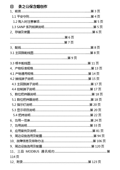
目录之公保含烟创作1、前言 (3)1.1 平安守则 (4)1.2 购入时注意事项 (5)1.3 SANP系列铭牌说明 (5)2、存储及装置 (6) (6) (7)3、配线 (8)3.1 主回路配线图 (8) (9)3.3 根本配线图 (11)4、产物标准规格 (13)4.1 产物通用规格 (14)4.2 接线端子说明 (15)4.3 主回路端子说明 (17)4.4 控制端子说明 (17)5、数位把持器说明 (18)5.1 数位把持器说明 (18)5.2 指示灯说明 (20)5.3 显示项目说明 (20)5.4 把持说明 (22)6、功用一览表 (24)7、功用说明 (33)8、应用案例及说明 (81)9、周边设施选用及配置 (94)10、故障信息及排除办法 (106)9、周边设施选用及配置 (120)11、三品MODBUS通讯规约 (114)12、附录 (123)附录一:机器外形及装置尺寸....................................................第123页 附录二:面板外形及装置尺寸....................................................第130页 11、产物保修卡.......................................................................第132页 12、产物保修协议.. (133)前 言感谢您选购SANP 系列变频器!本变频器是针对中国电网和各行业三相异步电动机调速的特点而设计;采用最新式微处置器,控制精度高、性能稳定、把持方便、呵护功用更加完善.在使用变频器前请详细阅读本使用说明书,以便正确装置使用本 产物,充沛发扬其功用,并确保使用平安.请妥善保管此说明书,以便日后调养、维护、检修时使用.变频器只要与主电源相连,就会有潜在的危险.电机或变频器装置欠妥将会造成设备损坏或人身伤亡,因此严格遵守本说明书的说明以及国度或外地的相关法规及平安标准. 【平安守则】 1、 请委托专业人员停止布线;如果布线欠妥能够会造成触电或火灾! 2、 请确认输入电源处于OFF (断开)位置后,方可停止布线作业! 3、 请务必衔接好接地线,而且担保接地线截面积!4、 请不要将交流电源衔接到变频器输出端子上(U 、V 、W ).5、请确认输入电源电压与本品的额外电压相符.一、前! SANP-0.75~415KW Series把持说明书Operating Instructions暗示高压正告 暗示制止把持 暗示一般正告 一、前6、 请不要将制动电阻直接衔接在直流端子(P 、N )上.7、 变频器运行时会发作高频搅扰,请注意是否会引起周边设备毛病举措. 8、务必装置好前盖板前方可接通输入电源.10、请勿用湿润的手停止把持,以防触电.11、在变频器接通电源期间,即使电机处于停止状态,也勿触摸变频器接线端子!12、变频器运转中严禁断开或投入电机.13、在开启“故障复位再启动”功用时,马达在因故障停止后会自动启动. 14、请不要通过接通(断开)输入电源使变频器运行(停止).【购入时注意事项】本机出厂前均做严格的包装处置,但思索运输途中的各种因素,装配前请特别注意下列事项,如有异常,请通知本产物经销商或本公 司相关人员:➢ 运输、搬运中是否损坏或变形.➢ 包装翻开时是否有SANP 系列变频器一台及使用说明书一本. ➢ 所订购的产物规格是否与铭牌相契合(额外电压及KW 数) . ➢ 内部装配的零件,配线及电路板是否有异常. ➢ 各端子是否紧锁,机器内是否有异物存在. ➢ 把持器按键是否正常. ➢有无合格证.【SANP series 铭牌说明】一、前电压品级:3P 暗示三相380V 电源 2P 暗示单相220V 电源 变频器容量为:G 通用型风机水泵型产物系列 三、产物标准规产物一般规格:产物通用规格:五位数码显示及状态指示灯显示频率、电流、转速、电压、计数器、温度、正反转状态、故障等.通信控制RS-485把持温度-10~40℃湿度0~95%相对湿度(不结露)振动0.5G 以下频率控制范围0.01~Hz精度%(-10~40℃);模拟式:0.1% (25±10℃)设定解析度Hz;模拟式:最年夜把持频率的1‰输出解析度Hz键盘设定方式面板编码器设定模拟设定方式外部电压 0~5V,0~10V,4~20mA,0~20mA.其它功用频率上下限、启动频率、停车频率、跳跃频率辨别设定一般控制加减速控制-6500 秒)任意选择V/F曲线可任意设定 V/F曲线转矩控制%Hz时可达 150%多功用输入端6个多功用输入端,实现外控8段速、内控4段速、UP、DOWN功用、计数器、外部急停等功用多功用输出端有5 个多功用输出端,实现运转中、零速、计数器、外部其它功用自动电压稳压减速停止或自由停止、直流刹车、自动复位再起动、频率跟踪、简易PLC顺序控制、扰动控制、载波可调,最高达20KHz等保护功能过载呵护电子电路呵护马达驱动器(恒转矩150%/1 分钟,风机类 120%/1 分钟)FUSE熔断呵护FUSE熔断,马达停止过电压220V级:直流电压>400V;380V级:直流电压>800V欠电压220V级:直流电压<200V;380V级:直流电压<400V 瞬间停电再起动瞬停后可以频率跟踪方式再起动失速避免加/减速运转中失速避免输出端短路电子线路呵护其它功用散热片过热呵护、反转限制、故障复位,参数锁定、PID一拖多等.接线端子说明:①控制端子排列:SANP-0.4~2.2G-2P、SANP-0.75G/1.5P-3P、SANP-1.5G/2.2P-3P、SANP-11G/15P~415G-3P②线端子排列:SANP-0.4~2.2G-2P、SANP-0.75G/1.5P-3P、SANP-1.5G/2.2P-3P、E R S T P PR U V WR S T E P PR U V WC- P E R S T U V W PRSANP-22G/30P-3P、SANP-30G/37P-3PSANP-37G/45P~160 G/185P-3PE R S T P P1 C- U V W主回路端子说明:端子记号内容说明R、S、T 电源输入端(220V级机种,单、三相共用,单相任选二个端子接入)U、V、W 变频器输出端P、PR 制动电阻衔接端P、P1 直流电抗器衔接端(使用直流电抗器时请裁撤短接片)P、C- 外部制动组件衔接端E 接地端子,按电工法规220V第三种接地,380V特种接地控制端子说明:端子记号内容说明出厂设定FWD 多功用输入一出厂设定为正转REV 多功用输入二出厂设定为反转X4 多功用输入三出厂设定为复位X3 多功用输入四出厂设定为高速X2 多功用输入五出厂设定为中速X1 多功用输入六出厂设定为低速Z1 多功用输入七出厂设定为无效Z2 多功用输入八出厂设定为无效CA 光栅编码器输入A 无效,仅在Pr076设置为6时有效CB 光栅编码器输入B 无效,仅在Pr076设置为6时有效CM/COM 数位控制信号共同端数字信号共用端子端子记号内容说明出厂设定E R S T P C- U V W+12 +12V 电源 最年夜输出电流200mA+10 速度设定用电源 +10VVIN 模拟电压频率指令 0~+10V 对应最高把持频率AOU 模拟电流输出 4-20mA PM 脉冲输出 1-6个脉冲输出AIN 模拟电流频率指令 4~20mA 对应最高把持频率GND 模拟控制信号共同端 模拟信号共用端子 DOG 多功用输出端子一(光耦合) DC24V/100mADOI多功用输出端子二(光耦合)S1A/S1B/S1C多功用输出端子三(常开/常闭) 3A/250V S2A/S2BS2B多功用输出端子四(常开) 3A/250VAC 、3A/30VDCAM 数位频率输出端子0-~10V S+ S-RS —485 通讯口【数位把持器说明】注:此图适用于注:此图适用于变频器运行状态及数据单元指示 数码显示窗口 调速器运行键 停止键正转、反转切数据移位键 数值+ 功用键数值- 确认、故障复位变频器运行状态及数据单元指示调速器 正转、反转切数据移位键数码显示窗口运行键 停止键 功用键 确认、故障复位数值+数值-注:此图适用于SANP-11G/15P~415G-3P指示灯说明:① 指示灯状态说明:指示灯 状态 说明FWD 亮 暗示马达处于正转状态 REV 亮 暗示马达处于反转状态 HZ 亮 显示设定频率或输出频率 A 亮 显示输出电流状态 r/min 亮 显示马达转速状态 HZA 亮 显示直流电压 Ar/min 亮 显示交流电压 HZr/min 亮 显示计数值 HZAr/min亮显示变频器温度②显示项目说明:显示项目指示灯状态说明HZ A r/min 暗示现在输出频率为50.00Hz¤ ○ ○HZ A r/min 暗示现在设定频率为50.00Hz¤ ○ ○HZ A r/min 暗示现在输出电流为3A ○ ¤ ○HZ A r/min 暗示现在输出转速为1440r/min○○¤调速器 变频器运行状态及数据单元指示数码显示窗口 正转、反转切数据移位键运行键停止键 功用键 确认、故障复位 数值+数值-六、数位把持器说明显示项目指示灯状态说明HZ A r/min暗示现在¤¤○HZ A r/min暗示现在输出交流电压为380V ¤○¤HZ A r/min暗示现在计数值268¤○¤HZ A r/min暗示现在变频器温度为℃¤¤¤HZ A r/min暗示PID目标值为50%○○○HZ A r/min暗示PID反应值为48%○○○HZ A r/min暗示本次上电运行时间为12小时¤¤○HZ A r/min暗示变频器总共运行时间为108小时○¤¤特殊显示项目:显示内容及说明启动时直流制动停机时直流制动显示内容及说明COPY 将主控板外面的数据拷贝(复制)到显示面板drEg 将显示面板外面的数据写入到主控板(必需担保之前已拷贝了正确数据)把持说明:SANP系列变频器的把持面板采用二级菜单构造停止参数设置等把持.二级菜单辨别为:功用参数组(一级菜单)→功用码设定值(二级菜单);关于不常接触变频器的人员,也可以用面板上的调速器停止参数修改及设定,比拟容易把持.顺时针为增加逆时针为增加,按下调速器相当于按下键!把持流程如下图所示.步伐面板显示菜单级别面板把持注释1. 零级菜单进入一级菜单功用键:一级菜单的进入或退出.步伐面板显示菜单级别面板把持注释2. 一级菜单改动参数组进入二级菜单.进入功用参数组(一级菜单)用移位键、数值修改键来改动参数组的参数;并按确认键停止确认,进入二级菜单.3. 二级菜单改动功用码设定值保管修改后的数值.进入功用码设定(二级菜单)用移位键、数值修改键来改动功用码的设定值;并按确认键停止确认,返回一级菜单.备注:1、在停止二级菜单把持时,可按键或返回一级菜单.两者的区别是:按下将设定参数保管后返回二级菜单,并自动转移到下一个功用码;而按键则直接返回到以后功用码.2、使用(递增)(递加)数值修改键务必反省“功用一览表”,修改后的数值契合变频器的设定范围和负载要求.3、在电机调速时,可以直接用面板上自带的“调速器”停止调速;顺时针为减速,逆时针为减速.【功用一览表】分类功用码功用设定范围及功用说明出厂值基本参Pr000 主频率设定0~400.00 Hz 0.00Pr001 最年夜输出电压0.1V—* 220/380Pr002 基准频率设定0.01~400.00 Hz八、功用一览表Pr164、Pr167~Pr168 保管Pr169 故障清除0:无效1:清除所有故障记载0 分类功用码功用设定范围及功用说明出厂值特殊功能参数Pr170 故障记载1注:——暗示无故障记载.NO Pr171 故障记载2 NO Pr172 故障记载3 NO Pr173 故障记载4 NO Pr174 最新毛病记载项171~174 171 Pr175 变频器类型0:恒转矩型 1:平方转矩型* Pr176 变频器型号编号按详细型号设定Pr177 变频器频率标准*Pr178 变频器电压品级*Pr179 变频器额外电流按详细型号设置* Pr180 软体版本号按详细情况设置* Pr181 出厂编号* * Pr182 出厂年、月、周* * Pr183~Pr189保管Pr190 4~20mA断路检测使能0:4~20mA断路不检测1:4~20mA断路检测1 Pr191~Pr249保管Pr250 数据拷贝0:无效1:将数据从主控板拷贝到显示面板2:将数据从显示面板写入主控板【功用说明】参数值功用名称设定范围单元出厂值Pr000 主频率设定说明:在运转频率来源设定为面板把持情况下,频率以Pr000设定值运行.在运行中可以用键来改动运转频率,在多段速运行中,主频率为第一段速频率.在设定为外控多段速运行时,如果把Pr034设定为2,即外部端子给定时,则第一段速由外部端子模拟量给定.主频率的设定受最年夜把持频率限制.相关参数:Pr034、Pr076,该参数在运行中可调.参数值功用名称设定范围单元出厂值Pr001 最年夜输出电0.1~* 220/380V参数值 功用名称 设定范围单元 出厂值 Pr008 频率上限 参数值 功用名称 设定范围单元 出厂值 Pr009频率下限说明:频率下限主要避免现场人员的误把持,避免马达因运转频率过低能够发作的过热或其他机械故障等.频率下限的设定必需小于频率上限的设定 值. 参数值 功用名称 设定范围 单元 出厂值 Pr010 参数锁定 0~11说明:0:未锁定1:锁定即参数锁定,除本参数和主频率Pr000外,其余参数不成修改. 此参数可避免非维护人员误设定其他参数,参数锁定后,可由键改动运转频率. 参数值 功用名称 设定范围 单元 出厂值 Pr011参数重置00~101说明:在参数值因故设置欠妥或不正常时,可将此参数设定为 08,恢复出厂8 15 220 50 VF恒转矩曲线 泵0 25 855 220 50 V F 低转矩曲线0 9 24 22050 VF高转矩曲线 0380 50 V F恒转矩曲线0 2516 110 380 50V F低转矩曲线20 45 380 50V F高转矩曲线参数值 功用名称 设定范围 单元 出厂值Pr043转矩赔偿 0.1~10.0% 0.1% 2.0%说明:此参数可以设定变频器在运转时自动输出额外的电压,以失掉较高的转矩,可以赔偿电机在低频时转矩缺乏现象.转矩补 偿不宜年夜,应依据实际情况,从小到年夜 慢慢向上设定.赔偿缺乏,会造成 电机在低频下转矩缺乏,赔偿过年夜,会造成转矩过年夜,对机械有所冲击,严重时会引起变频器跳脱.参数值 功用名称 设定范围单元 出厂值 Pr044 跳跃频率一 0.01 Hz Pr045 跳跃频率二 0.01 Hz Pr046 跳跃频率三 0.01 Hz Pr047跳跃频率范围0.10~2.00 Hz0.01 Hz说明:为避开机械共振点,设此三个频率跳跃点,当 Pr047=0时,所有跳跃频率无效,实际跳跃频率范围为 Pr047的两倍.如上图所示. 参数值 功用名称 设定范围单元 出厂值 Pr048 定时器一时间 设定1 Pr049定时器二时间 设定0~6500011定时器一为0.01S~650S 定时器,定时器二为1S~65000S 定时器,当多功用输入端子定时器开启闭合时,定时器开端计时,定时器抵达时,对应多功用输出接点 举措,定时器开启断开,多功用输出定时器时间抵达复位. 例如:设定Pr048=5.0S ,则当外控端子(多功用端子)有效时,经5.0S 时间,输出端子即为有效,用此信号可以控制其他相应信号.100%转矩赔偿。
安川(YASKAWA)606PC3变频器说明书

分类端子信号名称功能信号电平顺序输入信号1正转/停止运行在封闭,停止在OPEN光耦隔离输入24 VDC8毫安2反向运行/停止反向运行时关闭,停止在OPEN3故障复位输入复位闭合处4外部故障故障在非公开多功能接点输入;两种信号可供选择。
*5多段速参考。
1有效地关对于输入序列顺序6控制输入公共端公共端模拟输入信号10电源端子频率设定速度基准电源+ 12 V(允许电流20 mA最大。
)8频率参考0〜+ 10V /最大。
输出频率奥托+10 V(20kQ)9月4日至二十〇日最大毫安。
输出频率4至20 mA(250Q)11控制电路OV公共端-序列输出信号13期间在运行多功能光电耦合器输出运行低电平;两种信号可供选择。
“光电耦合器输出+ 48V 50mA以下在设定频率14频率一致信号低电平=输出频率对于序列输出7光耦合器输出常见的公共端FLT-A故障信号触点输出故障,A和C之间关闭,并在故障OPEN B和C触点容量250 VAC 之间:1A以下30 VDC:1A以下FLT-B常见FLT-C故障信号触点输出模拟输出信号12频率计0至10 V /最大。
输出频率。
可以选择电流表输出。
* 0至11 V最大。
2mA或更小11种常见我:请参见6-30页的多功能接点输入。
T:参见多功能光电耦合器输出6--33页。
4:请参见多功能模拟输出显示器6-24页。
2.安装逆变器2-307.快速参考三个表都包括在本节中,以便快速参考所有可以用于逆变器设置的常数。
在您尝试设置这些常量,请确保您知道如何设置密码,以使所有这些常量的改变和设置。
有关详细信息,请参阅第5-2页。
本节中的表格是指第一至第四位数字。
的数字被命名为示于下表。
•第一功能:无00无19•第二个功能:无20无29•第三个功能:无30无59第二位数字第三个数字第4位7-17.快速参考第一功能:无00无19第一功能:无00无19第一功能:无00无19功能编号名称说明初始设置注意参考不变组选择00密码0:设置密码/读取和第一功能(没有01到19)阅读成为可能。
- 1、下载文档前请自行甄别文档内容的完整性,平台不提供额外的编辑、内容补充、找答案等附加服务。
- 2、"仅部分预览"的文档,不可在线预览部分如存在完整性等问题,可反馈申请退款(可完整预览的文档不适用该条件!)。
- 3、如文档侵犯您的权益,请联系客服反馈,我们会尽快为您处理(人工客服工作时间:9:00-18:30)。
Cool MOS™ Power TransistorV DS @ T jmax 650V R DS(on)1.4ΩI D3.2AFeature• New revolutionary high voltage technology • Ultra low gate charge • Periodic avalanche rated • Extreme d v /d t rated • High peak current capability • Improved transconductance• P-TO-220-3-31: Fully isolated package (2500 VAC; 1 minute)Marking 03N60C303N60C303N60C3Type Package Ordering Code SPP03N60C3P-TO220-3-1Q67040-S4401SPB03N60C3P-TO263-3-2Q67040-S4391SPA03N60C3P-TO220-3-31-Maximum Ratings ParameterSymbol Value Unit SPA Continuous drain currentT C = 25 °C T C = 100 °CI D3.223.21)21)APulsed drain current, t p limited by T jmax I D puls 9.69.6A Avalanche energy, single pulseI D =2.4A, V DD =50VE AS 100100mJAvalanche energy, repetitive t AR limited by T jmax 2)I D =3.2A, V DD =50VE AR 0.20.2Avalanche current, repetitive t AR limited by T jmax I AR 3.2 3.2A Gate source voltage static V GS ±20±20V Gate source voltage AC (f >1Hz)V GS ±30±30Power dissipation, T C = 25°CP tot 3829.7W SPP_BOperating and storage temperatureT j , T stg-55...+150°CMaximum RatingsParameter Symbol Value Unit Drain Source voltage slopeV DS = 480 V, I D = 3.2 A, T j = 125 °Cd v/d t50V/nsThermal CharacteristicsParameter Symbol Values Unitmin.typ.max. Thermal resistance, junction - case R thJC -- 3.3K/W Thermal resistance, junction - case, FullPAK R thJC_FP-- 4.1 Thermal resistance, junction - ambient, leaded R thJA--62 Thermal resistance, junction - ambient, FullPAK R thJA_FP--80SMD version, device on PCB: @ min. footprint@ 6 cm2 cooling area 3)R thJA---3562-Soldering temperature,1.6 mm (0.063 in.) from case for 10s4)T sold --260°CElectrical Characteristics, at T j=25°C unless otherwise specifiedParameter Symbol Conditions Values Unitmin.typ.max. Drain-source breakdown voltage V(BR)DSS V GS=0V, I D=0.25mA600--V Drain-Source avalanchebreakdown voltageV(BR)DS V GS=0V, I D=3.2A-700-Gate threshold voltage V GS(th)I D=135µA, V GS=V DS 2.13 3.9Zero gate voltage drain current I DSS V DS=600V, V GS=0V,T j=25°C T j=150°C --0.5-170µAGate-source leakage current I GSS V GS=30V, V DS=0V--100nA Drain-source on-state resistance R DS(on)V GS=10V, I D=2AT j=25°C T j=150°C --1.263.81.4-ΩGate input resistance R G f=1MHz, open drain-10-Electrical CharacteristicsParameter Symbol Conditions Values Unitmin.typ.max. Transconductance g fs V DS≥2*I D*R DS(on)max,I D=2A- 3.4-SInput capacitance C iss V GS=0V, V DS=25V,f=1MHz -400-pFOutput capacitance C oss-150-Reverse transfer capacitance C rss-5-Effective output capacitance,5) energy related C o(er)V GS=0V,V DS=0V to 480V-12-Effective output capacitance,6)time relatedC o(tr)-26-Turn-on delay time t d(on)V DD=350V, V GS=0/10V,I D=3.2A,R G=20Ω-7-nsRise time t r-3-Turn-off delay time t d(off)-64100Fall time t f-1220Gate Charge CharacteristicsGate to source charge Q gs V DD=420V, I D=3.2A-2-nC Gate to drain charge Q gd-6-Gate charge total Q g V DD=420V, I D=3.2A,V GS=0 to 10V-1317Gate plateau voltage V(plateau)V DD=420V, I D=3.2A- 5.5-V1Limited only by maximum temperature2Repetitve avalanche causes additional power losses that can be calculated as PAV=E AR*f.3Device on 40mm*40mm*1.5mm epoxy PCB FR4 with 6cm² (one layer, 70 µm thick) copper area for drain connection. PCB is vertical without blown air.4Soldering temperature for TO-263: 220°C, reflow5Co(er)is a fixed capacitance that gives the same stored energy as C oss while V DS is rising from 0 to 80% V DSS.6Co(tr) is a fixed capacitance that gives the same charging time as C oss while V DS is rising from 0 to 80% V DSS.Electrical CharacteristicsParameter Symbol Conditions Values Unitmin.typ.max. Inverse diode continuousforward currentI S T C=25°C-- 3.2AInverse diode direct current,pulsedI SM--9.6 Inverse diode forward voltage V SD V GS=0V, I F=I S-1 1.2VReverse recovery time t rr V R=420V, I F=I S ,d i F/d t=100A/µs -250400nsReverse recovery charge Q rr- 1.8-µC Peak reverse recovery current I rrm-15-A Peak rate of fall of reverserecovery currentdi rr/dt T j=25°C---A/µs1 Power dissipation P tot = f (T C)Ptot2 Power dissipation FullPAKP tot = f (T C)Ptot3 Safe operating areaI D = f (V DS )parameter : D = 0 , T C=25°C3ID4 Safe operating area FullPAKI D = f (V DS)parameter: D = 0, T C = 25°C3ID5 Transient thermal impedance Z thJC = f (t p )parameter: D = t p /T-110 10 10 10 10 K/W Z t h J C6 Transient thermal impedance FullPAK Z thJC= f (t p )parameter: D = t p /t110 10 10 10 10 K/WZ t h J C7 Typ. output characteristic I D = f (V DS ); T j=25°C parameter: t p = 10 µs, V GSI D8 Typ. output characteristicI D = f (V DS ); T j =150°C parameter: t p = 10 µs, V GSI D9 Typ. drain-source on resistance R DS(on)=f(I D)parameter: T j=150°C, V GSRDS(on)10 Drain-source on-state resistanceR DS(on) = f (T j)parameter : I = 2 A, V = 10 VRDS(on)11 Typ. transfer characteristicsI D= f (V GS ); V DS≥ 2 x I D xR DS(on)maxparameter: t p = 10 µsID12 Typ. gate chargeV GS= f (Q Gate)parameter:I = 3.2 A pulsedVGS13 Forward characteristics of body diodeI F = f (V SD)parameter: T, t p = 10 µsIF14 Typ. switching timet = f (I D), inductive load, T j=125°Cpar.: V DS=380V, V GS=0/+13V, R G=20Ω15 Typ. switching timet = f (R G), inductive load, T j=125°Cpar.: V DS=380V, V GS=0/+13V, I D=3.2 A16 Typ. drain current sloped i/d t = f(R G), inductive load, T j = 125°Cpar.: V DS=380V, V GS=0/+13V, I D=3.2AA/µsdi/dt17 Typ. drain source voltage sloped v/d t = f(R G), inductive load, T j = 125°C par.: V DS=380V, V GS=0/+13V, I D=3.2AV/nsdv/dt18 Typ. switching lossesE = f (ID), inductive load, T j=125°Cpar.: V DS=380V, V GS=0/+13V, R G=20ΩmWsE19 Typ. switching lossesE = f(R G), inductive load, T j=125°Cpar.: V DS=380V, V GS=0/+13V, I D=3.2AmWsE20 Avalanche SOAI AR = f (t AR)par.: T j≤ 150 °C4IAR21 Avalanche energyE AS = f (T j)par.: I D = 2.4 A, V DD = 50 VE23 Avalanche power lossesP AR = f (f )parameter: E AR=0.2mJ6PAR22 Drain-source breakdown voltageV(BR)DSS = f (Tj)SPP03N60C3V(BR)DSS24 Typ. capacitancesC = f (V DS)parameter: V GS=0V, f=1 MHz25 Typ. C oss stored energy E oss =f (V DS )E Definition of diodes switching characteristicsP-TO-220-3-1All metal surfaces tin plated, except area of cut. Metal surface min. x=7.25, y=12.3P-TO-263-3-2 (D2-PAK)P-TO-220-3-31 (FullPAK)Please refer to mounting instructions (application note AN-TO220-3-31-01)Published byInfineon Technologies AG,Bereichs KommunikationSt.-Martin-Strasse 53,D-81541 München© Infineon Technologies AG 1999All Rights Reserved.Attention please!The information herein is given to describe certain components and shall not be considered as warranted characteristics.Terms of delivery and rights to technical change reserved.We hereby disclaim any and all warranties, including but not limited to warranties of non-infringement, regarding circuits, descriptions and charts stated herein.Infineon Technologies is an approved CECC manufacturer.InformationFor further information on technology, delivery terms and conditions and prices please contact your nearest Infineon Technologies Office in Germany or our Infineon Technologies Reprensatives worldwide (see address list). WarningsDue to technical requirements components may contain dangerous substances.For information on the types in question please contact your nearest Infineon Technologies Office.Infineon Technologies Components may only be used in life-support devices or systems with the expresswritten approval of Infineon Technologies, if a failure of such components can reasonably be expected tocause the failure of that life-support device or system, or to affect the safety or effectiveness of that deviceor system Life support devices or systems are intended to be implanted in the human body, or to supportand/or maintain and sustain and/or protect human life. If they fail, it is reasonable to assume that the healthof the user or other persons may be endangered.。
