86114-9500中文资料
BF861C,215;中文规格书,Datasheet资料
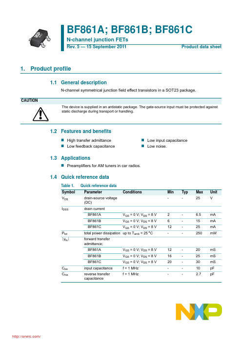
Min Typ Max Unit
25 -
-
V
0.2 -
0.5 -
0.8 -
-
-
1 V
1.5 V
2 V
1
V
2
-
6
-
12 -
-
-
6.5 mA 15 mA 25 mA 1 nA
© NXP B.V. 2011. All rights reserved.
Table 1. Symbol VDS IDSS
Ptot yfs
Ciss Crss
Quick reference data
Parameter
Conditions
drain-source voltage (DC)
drain current
BF861A
VGS = 0 V; VDS = 8 V
BF861B
Symbol Parameter
Conditions
Min
VDS VGSO VDGO IG Ptot Tstg Tj
drain-source voltage (DC) gate-source voltage drain-gate voltage (DC) forward gate current (DC) total power dissipation storage temperature operating junction temperature
VDS = 8 V. (1) VGS = 0 V. (2) VGS = 100 mV. (3) VGS = 200 mV. (4) VGS = 300 mV.
Fig 7. Typical output characteristics: BF861A.
6lb184中文资料

6lb184中文资料6lb184中文资料【用途】RS485/422电平转换电路【性能参数】双列贴片8脚封装。
TTL-RS485/422电平转换。
工作电压4.75-5.25V,典型5V。
【互换兼容】SN65LBC184D【6LB184的原厂(中文)资料数据手册脚功能参数封装】摘要:电子镇流器(Electrical ballast)是镇流器的一种,是指采用电子技术驱动电光源,使之产生所需照明的电子设备。
电子镇流器自身功耗低,有更佳的照明效果,消除了闪频现象,发光更稳定,而且可以调光。
文章采用AVR单片机作为控制芯片,通过电子镇流器进行调光和相关功能的控制,最大限度地发挥智能型镇流器的特点。
实际应用表明,文中的方法有效。
0 引言电子镇流器是新型节能产品,不仅能带动一些照明灯具,还可以和一些紫外灯结合在一起,对于空气净化和水源净化都有着非常大的作用。
当前,全世界都在大力提倡环境保护,电子镇流器间接地为环保提供了原动力。
AVR单片机是一款性价比较高的单片机,用这种单片机来对电子镇流器进行调光和时间采样非常合适,首先是AVR单片机本身较稳定,抗干扰能力比较强,其次是其本身的Harvard结构使得运行速度比较快,数据回读时间较快,可以实现实时在线控制。
1 AVR单片机介绍1.1 AVR单片机的特点与以往的8位单片机相比,AVR单片机采用Harvard结构,也就是程序总线和数据总线分开,并采用两级流水线,具备1MIPS/MHz的高速运行处理能力。
片内集成多种频率的RC振荡器、上电自动复位、看门狗、启动延时等功能模块,外围电路简单,系统更加稳定可靠。
大部分AVR片上资源丰富:带E2PROM、PWM、RTC、SPI、UART、TWI、ISP、AD、Analog Comparator、WDT等单元模块。
1.2 AVR单片机的PWM功能AVR单片机的定时器功能强大,以Atmega48为例,它有两个8位定时器和一个16位定时器,都具有硬件PWM功能。
86114-4000资料

FEATURES AND SPECIFICATIONSSPECIFICATIONSOptical EMI Adapters LC - 86115 Series MPO - 86114 Series SC -86116 SeriesLimit EMI Emissions In Front Panel Applications With Molex’s Optical EMI AdaptersEMI (Electro Magnetic Interference) shielding adapters are designed to address mechanical design requirements to limit EMI emissions from the equipment front panel. The adapters are constructed of die-cast bodies with an EMI gasket that seals the adapters to the panel. EMI adapters increase the shielding effectiveness while enhancing the front panel aesthetics compared to traditional plastic adapters.Our extensive EMI adapter product line includes SC, LC Duplex and MPO styles. The family includes both straight and angled mount adapters in both snap-in and screw mount configurations. The straight mount designs meet industry standard mounting dimensions. The angled mount design cut-outs are unique to each adapter. External shutters are standard on adapters, ensuring dust protection and eye laser safety. Reference Information Packaging: BagMates With: LC Duplex, SC, MPO connectorsDesigned In: SC – Inches, LC and MPO - Millimeters MechanicalMating Durability: IL<0.2dB over 200 cyclesPhysicalAdapter Housing:LC, MPO and SC - Zinc Die-cast LC 45°- Zinc Die-cast/Polymer Plating: Nickel ChromeAlignment Sleeve: Zirconia Ceramic Operating Temperature: -40 to +75°CMates with: Industry standard fiber optic connectorsFeatures and BenefitsI Die-cast adapter housings provide superior shielding effectivenessI Aperture is reduced to the minimum possible size to minimize EMI emissionsI EMI gaskets included create an EMI seal between the adapter and the mounting surfaceI Safety shutters included provide dust protection, eye safety and reduce EMI when no connector is installedI Screw or snap mount styles available provide mounting flexibility I Straight or 45°mounting orientations allow for lower cable exit profile APPLICATIONS I Telecommunication - High-speed line cards - Server blades - Router connectionsI Storage- ATM equipment- Gigabit Ethernet testing equipmentI Other Markets - Test equipment- Any front panel application where EMI is an issue(Offers a more robust and visually appealing adapter than traditional plastic adapters)ORDERING INFORMATIONOptical EMI Adapters LC - 86115 Series MPO - 86114 Series SC -86116 SeriesAmericas Headquarters Lisle, Illinois 60532 U.S.A.1-800-78MOLEX amerinfo@ Far East North Headquarters Yamato, Kanagawa, Japan 81-462-65-2324feninfo@ Far East South Headquarters Jurong, Singapore 65-6-268-6868fesinfo@ European Headquarters Munich, Germany 49-89-413092-0eurinfo@Corporate Headquarters 2222 Wellington Ct.Lisle, IL 60532 U.S.A.630-969-4550Fax:630-969-1352Visit our Web site at http://www.molex/product/fiber/emiadapter.htmlOrder No. USA-189 Rev. 4Printed in USA/JI/2004.08©2004, MolexSC EMI AdaptersSC EMI AdaptersLC Duplex EMI AdaptersLC Duplex EMI AdaptersMPO EMI AdaptersMPO EMI AdaptersPart Number Type Mount Style Mount Angle Shutter Mount From 86116-2000SC EMI Adapter Snap Straight One Side Front/Rear 86116-2100SC EMI AdapterScrewStraightOne SideFront/RearPart Number Type Mount Style Mount AngleShutter Mount From 86115-3100LC Duplex Adapter Screw 45°One Side Front/Rear 86115-4100LC Duplex Adapter Snap 45°One Side Front/Rear 86115-1100LC Duplex Adapter Screw Straight None Front/Rear 86115-1110LC Duplex Adapter Screw Straight One Side Front/Rear 86115-1120LC Duplex Adapter Screw Straight Two Sides Front/Rear 86115-2100LC Duplex Adapter Snap Straight None Front/Rear 86115-2110LC Duplex Adapter Snap Straight One Side Front/Rear 86115-2120LC Duplex Adapter Snap Straight Two Sides Front/Rear 86115-3200LC Duplex AdapterSingle Screw45°One SideRear OnlyPart Number Type Mount Style Mount Angle Shutter Mount From 86114-1100MPO EMI Adapter Screw Straight One Side Front/Rear 86114-1200MPO EMI Adapter Snap Straight One Side Front/Rear 86114-3000MPO EMI Adapter Screw 45°One Side Front Only 86114-4000MPO EMI Adapter Snap 45°One Side Front Only 86114-3200MPO Quad EMI AdapterScrew45°NoneRear Only。
ZXM10 EISU(V1.0)增强智能型采集单元用户手册
结构合理
图表说明
通俗易懂
详细说明
内容结构
内容详细
您对本资 料的改进 建议
内容深度 表达简洁 增加图形
增加实例
增加 FAQ
其他
您对中兴 通讯用户 资料的其 他建议
2
第1章 概述
摘要
本章介绍 ZXM10 EISU 增强智能型采集单元的型号说明、主要功 能以及技术特性和参数。
1.1 引言
随着移动通信覆盖面的日益扩大,移动通信基站也星罗棋布般的 遍及全国各地。移动通信基站所处的大多数地区,其电力网情况 不稳定,同时机房基本上都是无人值守,所以对基站进行集中监 控比本地网集中监控有着更为迫切的需求。E-GUARD 基站集中监 控系统正是为了适应这种要求而开发的一种专用监控系统。它主 要用于对基站的环境和动力设备进行监控。
1.5 防雷指标
EISU 增强型智能采集单元的技术特性和参数详见表 1.5-1。
试验端口
冲击电流 8/20us 正负级各 5 次
表1.5-1 EISU 技术特性和参数
通用 AI/DI/DO 口
DC 电源口
串口
差模 2KA
差模 5KA 差模 2KA
共模 3KA
共模 5KA 共模 3KA
E1 接口 差模 2KA 共模 3KA
2. 具备专用的常用传感器接口,可以接入 1 路数字温度传感 器、2 路蓄电池总电压、1 路烟雾传感器。
3. 提供多个智能设备协议解析接口,完成智能设备的数据采 集和控制;(4~6 个,可接入 20 个智能设备)。
4. 具备图片监控功能,提供 2 路 USB 摄像头接口,完成图片 数据的处理、存储和转发;图片分辨率可达到 640×480。
ZXM10 EISU(V1.0) 增强智能型采集单元
ADM8611LABKS-RL中文资料
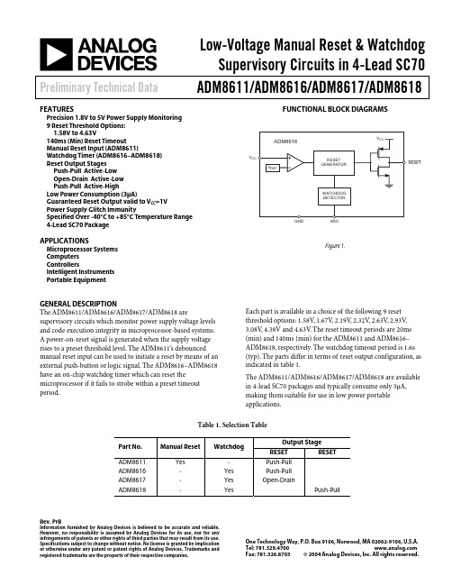
Low-Voltage Manual Reset & WatchdogSupervisory Circuits in 4-Lead SC70 Preliminary Technical Data ADM8611/ADM8616/ADM8617/ADM8618Rev.PrBInformation furnished by Analog Devices is believed to be accurate and reliable.However, no responsibility is assumed by Analog Devices for its use, nor for anyinfringements of patents or other rights of third parties that may result from its use. Specifications subject to change without notice. No license is granted by implication or otherwise under any patent or patent rights of Analog Devices. Trademarks and registered trademarks are the property of their respective companies.One Technology Way, P.O. Box 9106, Norwood, MA 02062-9106, U.S.A. Tel: Fax: 781.326.8703© 2004 Analog Devices, Inc. All rights reserved.FEATURESPrecision 1.8V to 5V Power Supply Monitoring9 Reset Threshold Options:1.58V to 4.63V140ms (Min) Reset TimeoutManual Reset Input (ADM8611)Watchdog Timer (ADM8616–ADM8618)Reset Output StagesPush-Pull Active-LowOpen-Drain Active-LowPush-Pull Active-HighLow Power Consumption (3µA)Guaranteed Reset Output valid to V CC=1VPower Supply Glitch ImmunitySpecified Over -40°C to +85°C Temperature Range4-Lead SC70 PackageAPPLICATIONSMicroprocessor SystemsComputersControllersIntelligent InstrumentsPortable EquipmentGENERAL DESCRIPTIONThe ADM8611/ADM8616/ADM8617/ADM8618 are supervisory circuits which monitor power supply voltage levels and code execution integrity in microprocessor-based systems.A power-on-reset signal is generated when the supply voltage rises to a preset threshold level. The ADM8611’s debounced manual reset input can be used to initiate a reset by means of an external push-button or logic signal. The ADM8616–ADM8618 have an on-chip watchdog timer which can reset the microprocessor if it fails to strobe within a preset timeout period.FUNCTIONAL BLOCK DIAGRAMSRESET VFigure 1.Each part is available in a choice of the following 9 reset threshold options: 1.58V, 1.67V, 2.19V, 2.32V, 2.63V, 2.93V,3.08V,4.38V and 4.63V. The reset timeout periods are 20ms (min) and 140ms (min) for the ADM8611 and ADM8616–ADM8618, respectively. The watchdog timeout period is 1.6s (typ). The parts differ in terms of reset output configuration, as indicated in table 1.The ADM8611/ADM8616/ADM8617/ADM8618 are available in 4-lead SC70 packages and typically consume only 3µA, making them suitable for use in low power portable applications.Table 1. Selection TableADM8611/ADM8616/ADM8617/ADM8618 Preliminary Technical DataADM8611/ADM8616/ADM8617/ADM8618—SPECIFICATIONSTable 2. V CC=Full Operating Range, T A=T MIN to T MAX, unless otherwise notedRev. PrB | Page 2 of 7Preliminary Technical DataADM8611/ADM8616/ADM8617/ADM8618Rev. PrB | Page 3 of 7ABSOLUTE MAXIMUM RATINGSTable 3. T A = 25°C unless otherwise noted.Stresses above those listed under Absolute Maximum Ratings may cause permanent damage to the device. This is a stress rating only and functional operation of the device at these or any other conditions above those indicated in the operational section of this specification is not implied. Exposure to absolute maximum rating conditions for extended periods may affect device reliability.ADM8611/ADM8616/ADM8617/ADM8618Preliminary Technical DataRev. PrB | Page 4 of 7PIN CONFIGURATIONS AND FUNCTIONAL DESCRIPTIONSRESET V CCMR /WDITable 4. Pin Functional DescriptionsESD CAUTIONESD (electrostatic discharge) sensitive device. Electrostatic charges as high as 4000 V readily accumulate on the human body and test equipment and can discharge without detection. Although this product features proprietary ESD protection circuitry, permanent damage may occur on devices subjected to high energy electrostatic discharges. Therefore, proper ESD precautions are recommended to avoid performance degradation or loss of functionality.Preliminary Technical DataADM8611/ADM8616/ADM8617/ADM8618Rev. PrA | Page 5 of 7OUTLINE DIMENSIONS0.150.10 COPLANARITYP ACKAGE OUTLINE CORRESPONDS IN FULL TO EIAJ SC82EXCEPT FOR WIDTH OF PIN-2 AS SHOWNFigure 2. 4-Lead Plastic Surface Mount Package [SC70](KS-4)Dimensions shown in millimetersADM8611/ADM8616/ADM8617/ADM8618 Preliminary Technical DataORDERING GUIDE (ADM8611/ADM8616)Model1Reset Threshold (V)Temperature Range Quantity Package Type Branding ADM8611LABKS-RL 4.63 -40°C to +85°C 10k SC70-4 N0F ADM8611LABKS-RL7 4.63 -40°C to +85°C 3k SC70-4 N0F ADM8611MABKS-RL 4.38 -40°C to +85°C 10k SC70-4 N0F ADM8611MABKS-RL7 4.38 -40°C to +85°C 3k SC70-4 N0F ADM8611TABKS-RL 3.08 -40°C to +85°C 10k SC70-4 N0F ADM8611TABKS-RL7 3.08 -40°C to +85°C 3k SC70-4 N0F ADM8611SABKS-RL 2.93 -40°C to +85°C 10k SC70-4 N0F ADM8611SABKS-RL7 2.93 -40°C to +85°C 3k SC70-4 N0F ADM8611RABKS-RL 2.63 -40°C to +85°C 10k SC70-4 N0F ADM8611RABKS-RL7 2.63 -40°C to +85°C 3k SC70-4 N0F ADM8611ZABKS-RL 2.32 -40°C to +85°C 10k SC70-4 N0F ADM8611ZABKS-RL7 2.32 -40°C to +85°C 3k SC70-4 N0F ADM8611YABKS-RL 2.19 -40°C to +85°C 10k SC70-4 N0F ADM8611YABKS-RL7 2.19 -40°C to +85°C 3k SC70-4 N0F ADM8611WABKS-RL 1.67 -40°C to +85°C 10k SC70-4 N0F ADM8611WABKS-RL7 1.67 -40°C to +85°C 3k SC70-4 N0F ADM8611VABKS-RL 1.58 -40°C to +85°C 10k SC70-4 N0F ADM8611VABKS-RL7 1.58 -40°C to +85°C 3k SC70-4 N0F ADM8616LAKS-RL 4.63 -40°C to +85°C 10k SC70-4 N0G ADM8616LAKS-RL7 4.63 -40°C to +85°C 3k SC70-4 N0G ADM8616MAKS-RL 4.38 -40°C to +85°C 10k SC70-4 N0G ADM8616MAKS-RL7 4.38 -40°C to +85°C 3k SC70-4 N0G ADM8616TAKS-RL 3.08 -40°C to +85°C 10k SC70-4 N0G ADM8616TAKS-RL7 3.08 -40°C to +85°C 3k SC70-4 N0G ADM8616SAKS-RL 2.93 -40°C to +85°C 10k SC70-4 N0G ADM8616SAKS-RL7 2.93 -40°C to +85°C 3k SC70-4 N0G ADM8616RAKS-RL 2.63 -40°C to +85°C 10k SC70-4 N0G ADM8616RAKS-RL7 2.63 -40°C to +85°C 3k SC70-4 N0G ADM8616ZAKS-RL 2.32 -40°C to +85°C 10k SC70-4 N0G ADM8616ZAKS-RL7 2.32 -40°C to +85°C 3k SC70-4 N0G ADM8616YAKS-RL 2.19 -40°C to +85°C 10k SC70-4 N0G ADM8616YAKS-RL7 2.19 -40°C to +85°C 3k SC70-4 N0G ADM8616WAKS-RL 1.67 -40°C to +85°C 10k SC70-4 N0G ADM8616WAKS-RL7 1.67 -40°C to +85°C 3k SC70-4 N0G ADM8616VAKS-RL 1.58 -40°C to +85°C 10k SC70-4 N0G ADM8616VAKS-RL7 1.58 -40°C to +85°C 3k SC70-4 N0GRev. PrB | Page 6 of 7Preliminary Technical DataADM8611/ADM8616/ADM8617/ADM8618Rev. PrA | Page 7 of 7ORDERING GUIDE (ADM8617/ADM8618)1Entries in bold type are standard models. Contact factory for availability of non-standard models.ModelReset Threshold (V)Temperature Range Quantity Package TypeBranding ADM8617LACYKS-RL 4.63 -40°C to +85°C 10k SC70-4N0H ADM8617LACYKS-RL7 4.63 -40°C to +85°C 3k SC70-4 N0H ADM8617MACYKS-RL 4.38 -40°C to +85°C 10k SC70-4 N0H ADM8617MACYKS-RL7 4.38 -40°C to +85°C 3k SC70-4 N0H ADM8617TACYKS-RL 3.08 -40°C to +85°C 10k SC70-4 N0H ADM8617TACYKS-RL7 3.08 -40°C to +85°C 3k SC70-4 N0H ADM8617SACYKS-RL 2.93 -40°C to +85°C 10k SC70-4 N0H ADM8617SACYKS-RL7 2.93 -40°C to +85°C 3k SC70-4 N0H ADM8617RACYKS-RL 2.63 -40°C to +85°C 10k SC70-4 N0H ADM8617RACYKS-RL7 2.63 -40°C to +85°C 3k SC70-4 N0H ADM8617ZACYKS-RL 2.32 -40°C to +85°C 10k SC70-4 N0H ADM8617ZACYKS-RL7 2.32 -40°C to +85°C 3k SC70-4 N0H ADM8617YACYKS-RL 2.19 -40°C to +85°C 10k SC70-4 N0H ADM8617YACYKS-RL7 2.19 -40°C to +85°C 3k SC70-4 N0H ADM8617WACYKS-RL 1.67 -40°C to +85°C 10k SC70-4 N0H ADM8617WACYKS-RL7 1.67 -40°C to +85°C 3k SC70-4 N0H ADM8617VACYKS-RL 1.58 -40°C to +85°C 10k SC70-4 N0H ADM8617VACYKS-RL7 1.58 -40°C to +85°C 3k SC70-4 N0H ADM8618LACYKS-RL 4.63 -40°C to +85°C 10k SC70-4 N0J ADM8618LACYKS-RL7 4.63 -40°C to +85°C 3k SC70-4 N0J ADM8618MACYKS-RL 4.38 -40°C to +85°C 10k SC70-4 N0J ADM8618MACYKS-RL7 4.38 -40°C to +85°C 3k SC70-4 N0J ADM8618TACYKS-RL 3.08 -40°C to +85°C 10k SC70-4 N0J ADM8618TACYKS-RL7 3.08 -40°C to +85°C 3k SC70-4 N0J ADM8618SACYKS-RL 2.93 -40°C to +85°C 10k SC70-4 N0J ADM8618SACYKS-RL7 2.93 -40°C to +85°C 3k SC70-4 N0J ADM8618RACYKS-RL 2.63 -40°C to +85°C 10k SC70-4 N0J ADM8618RACYKS-RL7 2.63 -40°C to +85°C 3k SC70-4 N0J ADM8618ZACYKS-RL 2.32 -40°C to +85°C 10k SC70-4 N0J ADM8618ZACYKS-RL7 2.32 -40°C to +85°C 3k SC70-4 N0J ADM8618YACYKS-RL 2.19 -40°C to +85°C 10k SC70-4 N0J ADM8618YACYKS-RL7 2.19 -40°C to +85°C 3k SC70-4 N0J ADM8618WACYKS-RL 1.67 -40°C to +85°C 10k SC70-4 N0J ADM8618WACYKS-RL7 1.67 -40°C to +85°C 3k SC70-4 N0J ADM8618VACYKS-RL 1.58 -40°C to +85°C 10k SC70-4 N0J ADM8618VACYKS-RL71.58-40°C to +85°C3kSC70-4N0J© 2004 Analog Devices, Inc. All rights reserved. Trademarks and registered trademarks are the property of their respective companies. Printed in the U.S.A. PR04795-0-3/04(PrA)。
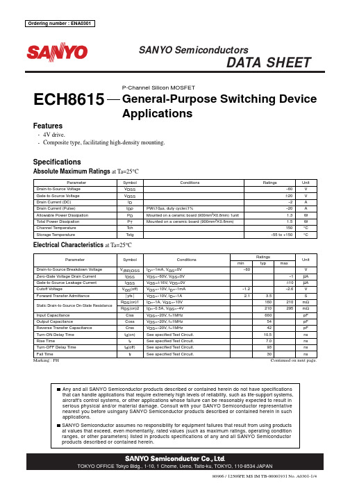
ECH8615中文资料
--0.5
--1
0 0 --0.1 --0.2 --0.3 --0.4 --0.5 --0.6 --0.7 --0.8 --0.9 --1.0
0 --2.5 --3.0 --3.5 IT10645
Drain-to-Source Voltage, VDS -- V
450
IT10644
RDS(on) -- VGS
4V drive. Composite type, facilitating high-density mounting.
Specifications
Absolute Maximum Ratings at Ta=25°C
Parameter Drain-to-Source Voltage Gate-to-Source Voltage Drain Current (DC) Drain Current (Pulse) Allowable Power Dissipation Total Power Dissipation Channel Temperature Storage Temperature Symbol VDSS VGSS ID IDP PD PT Tch Tstg PW≤10µs, duty cycle≤1% Mounted on a ceramic board (900mm2!0.8mm) 1unit Mounted on a ceramic board (900mm2!0.8mm) Conditions Ratings --60 ± 20 --2 --20 1.3 1.5 150 --55 to +150 Unit V V A A W W °C °C
--40
--20
0
20
40
60
RB861YT2R;中文规格书,Datasheet资料

Limits 5 10 125 -40 to +125
Unit V mA 㷄 㷄
Typ. 0.85
Max. 0.29 30 1.10
㪈㪇㪇 㪐㪇 㪩㪜㪭㪜㪩㪪㪜㩷㪚㪬㪩㪩㪜㪥㪫㪑㪠㪩㩿㫌㪘㪀 㪏㪇 㪎㪇 㪍㪇 㪌㪇 㪋㪇 㪊㪇 㪉㪇 㪈㪇 㪘㪭㪜㪑㪎㪅㪏㫌㪘 㪫㪸㪔㪉㪌㷄 㪭㪩㪔㪈㪭 㫅㪔㪊㪇㫇㪺㫊
㪉 㪈㪅㪐 㪚㪘㪧㪘㪚㪠㪫㪘㪥㪚㪜㩷㪙㪜㪫㪮㪜㪜㪥 㪫㪜㪩㪤㪠㪥㪘㪣㪪㪑㪚㫋㩿㫇㪝㪀 㪈㪅㪏 㪈㪅㪎 㪈㪅㪍 㪈㪅㪌 㪈㪅㪋 㪈㪅㪊 㪈㪅㪉 㪈㪅㪈 㪈 㪠㪩㩷㪛㪠㪪㪧㪜㪩㪪㪠㪦㪥㩷㪤㪘㪧 㪚㫋㩷㪛㪠㪪㪧㪜㪩㪪㪠㪦㪥㩷㪤㪘㪧 㪘㪭㪜㪑㪈㪅㪏㪈㫇㪝 㪫㪸㪔㪉㪌㷄 㪽㪔㪈㪤㪟㫑 㪭㪩㪔㪇㪭 㫅㪔㪈㪇㫇㪺㫊
Unit V μA pF
Conditions IF=1mA VR=1V VR=0V , f=1MHz
Rev.B
1/2
/
㪈㪅㪍㪌㫧㪇㪅㪇㪈
RB861Y
Diodes
zElectrical characteristic curves (Ta=25qC)
㪈㪇 㪫㪸㪔㪈㪉㪌㷄 㪩㪜㪭㪜㪩㪪㪜㩷㪚㪬㪩㪩㪜㪥㪫㪑㪠㪩㩿㫌㪘㪀 㪈㪇㪇㪇 㪫㪸㪔㪈㪉㪌㷄 㪚㪘㪧㪘㪚㪠㪫㪘㪥㪚㪜㩷㪙㪜㪫㪮㪜㪜㪥 㪫㪜㪩㪤㪠㪥㪘㪣㪪㪑㪚㫋㩿㫇㪝㪀 㪈㪇 㪽㪔㪈㪤㪟㫑
RB861Y
Diodes
Schottky barrier diode
RB861Y
zApplications High frequency detection zDimensions (Unit : mm)
86160-0000中文资料
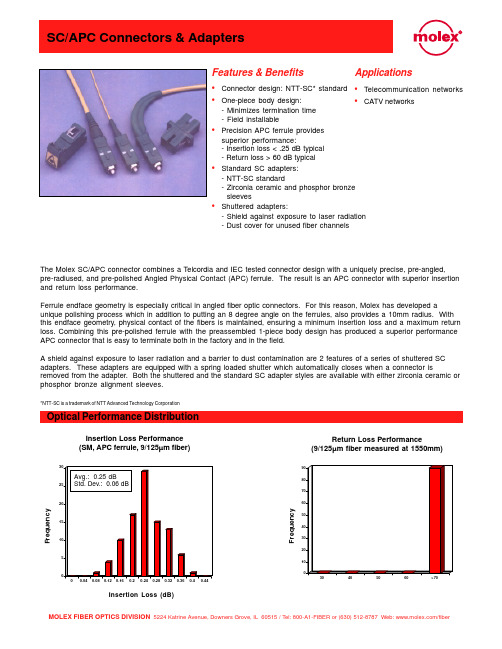
•Connector design: NTT-SC* standard•One-piece body design:- Minimizes termination time - Field installable•Precision APC ferrule provides superior performance:- Insertion loss < .25 dB typical - Return loss > 60 dB typical •Standard SC adapters:- NTT-SC standard- Zirconia ceramic and phosphor bronze sleeves•Shuttered adapters:- Shield against exposure to laser radiation - Dust cover for unused fiber channelsFeatures & Benefits Optical Performance DistributionInsertion Loss Performance (SM, APC ferrule, 9/125µm fiber)Return Loss Performance(9/125µm fiber measured at 1550mm)The Molex SC/APC connector combines a Telcordia and IEC tested connector design with a uniquely precise, pre-angled,pre-radiused, and pre-polished Angled Physical Contact (APC) ferrule. The result is an APC connector with superior insertion and return loss performance.Ferrule endface geometry is especially critical in angled fiber optic connectors. For this reason, Molex has developed aunique polishing process which in addition to putting an 8 degree angle on the ferrules, also provides a 10mm radius. With this endface geometry, physical contact of the fibers is maintained, ensuring a minimum insertion loss and a maximum return loss. Combining this pre-polished ferrule with the preassembled 1-piece body design has produced a superior performance APC connector that is easy to terminate both in the factory and in the field.A shield against exposure to laser radiation and a barrier to dust contamination are 2 features of a series of shuttered SC adapters. These adapters are equipped with a spring loaded shutter which automatically closes when a connector isremoved from the adapter. Both the shuttered and the standard SC adapter styles are available with either zirconia ceramic or phosphor bronze alignment sleeves.*NTT-SC is a trademark of NTT Advanced Technology CorporationApplications •Telecommunication networks•CATV networksF r e q u e n c yInsertion Loss (dB)F r e q u e n c yMOLEX FIBER OPTICS DIVISION 5224 Katrine Avenue, Downers Grove, IL 60515 / Tel: 800-A1-FIBER or (630) 512-8787 Web: /fiberMechanical DimensionsSC/APC Tunable Connector, 3mm Boot StyleSC/APC Tunable Connector, 900µm Boot StyleSC/APC Tunable Connector, 90º Boot StyleAll dimensions in INCHESMechanical DimensionsSC AdapterSC Adapter with ShutterAll dimensions in INCHESmmRECOMMENDED MOUNTING HOLEStandard Part NumbersOrder Number Description Hole size Cable size86065-5000SC connector, APC, zirconia ferrule126µm 3.0mm86065-5300SC connector, APC, zirconia ferrule126µm 2.4mm86065-5500SC connector, APC, zirconia ferrule, buffered fiber126µm900µm buffered fiber 86065-5400SC connector, APC, zirconia ferrule, 90º boot126µm 3.0mm86065-5600SC connector, APC, zirconia ferrule, 90º boot126µm 2.4mm86161-0000SC adapter, zirconia alignment sleeve, blue housing86160-0000SC adapter, phosphor bronze alignment sleeve, blue housing86161-3000SC adapter, zirconia alignment sleeve, green housing86160-3000SC adapter, phosphor bronze alignment sleeve, green housing86170-0550SC adapter, zirconia alignment sleeve, blue housing, shutter86170-0520SC adapter, zirconia alignment sleeve, green housing, shutter86171-0550SC adapter, phosphor bronze alignment sleeve, blue housing, shutter86171-0520SC adapter, phosphor bronze alignment sleeve, green housing, shutter86001-0098 Rev. 1 USA/30MFO/2000.09 ©2000, Molex Molex reserves the right to make any changes to the product(s) or information contained herein without notice. No liability is assumed as a result of their use or application.。
PAM8610中文资料
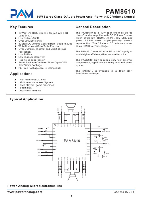
The PAM8610 is a 10W (per channel) stereo class-D audio amplifier with DC Volume Control which offers low THD+N (0.1%), low EMI, and good PSRR thus high-quality sound reproduction. The 32 steps DC volume control has a +32dB to -75dB range.
26
AVCC High-voltage analog power supply (7V to 15V)
2.5V Reference for analog cells, as well as reference for unused audio input
27
V2P5
when using single-ended inputs.
3
08/2008 Rev 1.2
元器件交易网
PAM8610
10W Stereo Class-D Audio Power Amplifier with DC Volume Control
Pin Descriptions
Pin Number Name
The PAM8610 is available in a 40pin QFN 6mm*6mm package.
n Flat monitor /LCD TVS n Multi-media speaker System n DVD players, game machines n Boom Box n Music instruments
5
GS-2406T PLUS GS-3405T PLUS Series 热转式 热感式 SUR

GS-2406T PLUS / GS-3405T PLUS / Series热转式/热感式SURPASS PLUS条码印表机使用手册Ver.1.1.3Agency Compliance and ApprovalsEN 55032, Class AEN 55024This is a class A product. In a domestic environment this product may cause radiointerference in which case the user may be required to take adequate measures.FCC part 15B, Class AThis equipment has been tested and found to comply with the limits for a Class Adigital device, pursuant to Part 15 of the FCC Rules. These limits are designed toprovide reasonable protection against harmful interference when the equipment isoperated in a commercial environment. This equipment generates, uses, and canradiate radio frequency energy and, if not installed and used in accordance with themanufacturer’s instruction manual, may cause harmful interference with radiocommunications. Operation of this equipment in a residential area is likely to causeharmful interference, in which case you will be required to correct the interference atyour own expense.FCC 符合声明此设施符合第15 部份的规则。
MAX9814中文资料ver2.0
```````````````````````````````````গၤNBY:925ဵጙࢅ߅۾Ăອᒠ൱యज़हࡍLjดᒙᔈࣅᐐፄ఼ᒜ)BHD*ጲૺࢅᐅဉ൱యज़ມᒙăকୈૹ߅ࢅᐅဉ༄ᒙहࡍĂభܤᐐፄहࡍ)WHB*Ăၒ߲हࡍĂ൱యज़ມኹखညጲૺBHD఼ᒜ࢟വăࢅᐅဉ༄ᒙहࡍࡼᐐፄৼࢾᆐ23eCLjऎWHBᐐፄభጲোၒ߲࢟ኹਜ਼BHDඡሢᏴ31eCਜ਼1eCᒄମᔈࣅࢯஂăၒ߲हࡍᎌ9eCĂ29eCਜ਼39eCྯᒬభኡᐐፄăᏴᎌኹჁࡼᄟୈሆLjहࡍೊభဧᔐᐐፄࡉࡵ51eCĂ61eC71eCăྯზၫᔊၒྜྷܠ߈ᒙၒ߲हࡍࡼᐐፄăᅪݝ࢟ᔜॊኹ఼ᒜBHDඡሢLjৈ࢟ྏభᒙࣅ0ျहဟମăྯზၫᔊၒྜྷથభܠ߈ᒙࣅᎧျहဟମࡼ܈LjBHDࡼۣߒဟମৼࢾᒋᆐ41ntăࢅᐅဉ൱యज़ມᒙखညถᆐࡍࣶၫᓘᄏ൱యज़ᄋມኹăNBY:925ݧஂဏహମࡼ25୭UEGOॖᓤăকୈਖࢾᔫᏴ.51°Dᒗ,96°D౫ᐱᆨࣞपᆍă```````````````````````````````````።```````````````````````````````````ᄂቶ♦ᔈࣅᐐፄ఼ᒜ)BHD*♦ྯᒬᐐፄᒙ)51eCĂ61eCĂ71eC*♦భܠ߈ࣅဟମ♦భܠ߈ࣅᎧျह܈♦3/8Wᒗ6/6W࢟Ꮞ࢟ኹपᆍ♦ࢅࡉ41oW0√I{ࡼၒྜྷݬఠᐅဉමࣞ♦ࢅࡉ1/15&!)࢜ቯᒋ*ࡼUIE ♦ࢅਈࣥෝါ♦ดݝᄋࢅᐅဉ൱యज़ມᒙLj3W♦ݧஂဏహମࡼ25୭UEGO!)4nn!y!4nn*ॖᓤ♦.51°Dᒗ,96°D౫ᐱᆨࣞपᆍNBY:925ᎌBHDਜ਼ࢅᐅဉ൱యज़ມᒙ࢟വࡼ൱యज़हࡍ________________________________________________________________Maxim Integrated Products 1```````````````````````````````ࢾ৪ቧᇦ`````````````````````````````````````````````````````````````````````````````````଼છౖᅄ۾ᆪဵ፞ᆪၫᓾ೯ࡼፉᆪLjᆪᒦభถࡀᏴडፉࡼݙᓰཀྵࡇᇙăྙኊጙݛཀྵཱྀLj༿Ᏼิࡼଐᒦݬఠ፞ᆪᓾ೯ăᎌਈଥৃĂૡૺࢿ৪ቧᇦLj༿ೊNbyjnᒴሾ၉ᒦቦǖ21911!963!235:!)۱ᒦਪཌ*Lj21911!263!235:!)ฉᒦਪཌ*LjषᆰNbyjnࡼᒦᆪᆀᐶǖdijob/nbyjn.jd/dpnă+ܭာᇄ)Qc*0९SpITܪᓰࡼॖᓤăU!>!௳ࡒ۞ᓤă*FQ!>!ൡă୭ᒙᏴၫᓾ೯ࡼᔢઁ߲ăၫ൩ሤ૦ၫᔊስ૦QEB ౸ዀऐ૦Ꭵಘᇹᄻ)ಿྙLjఌ౯PL*ၷሶᄰቧᓤᒙອᒠܣቑါഺስ૦JQ࢟જ0࢟જ્ፇN B Y :925ᎌBHDਜ਼ࢅᐅဉ൱యज़ມᒙ࢟വࡼ൱యज़हࡍABSOLUTE MAXIMUM RATINGSELECTRICAL CHARACTERISTICS(V DD = 3.3V, SHDN = V DD , C CT = 470nF, C CG = 2μF, GAIN = V DD , T A = T MIN to T MAX , unless otherwise specified. Typical values are at T A = +25°C.) (Note 1)Stresses beyond those listed under “Absolute Maximum Ratings” may cause permanent damage to the device. These are stress ratings only, and functional operation of the device at these or any other conditions beyond those indicated in the operational sections of the specifications is not implied. Exposure to absolute maximum rating conditions for extended periods may affect device reliability.V DD to GND..............................................................-0.3V to +6V All Other Pins to GND.................................-0.3V to (V DD + 0.3V)Output Short-Circuit Duration.....................................Continuous Continuous Current (MICOUT, MICBIAS).......................±100mA All Other Pins....................................................................±20mAContinuous Power Dissipation (T A = +70°C)14-Pin TDFN-EP(derate 16.7mW/°C above +70°C)........................1481.5mW Operating Temperature Range ...........................-40°C to +85°C Junction Temperature......................................................+150°C Lead Temperature (soldering, 10s).................................+300°C Bump Temperature (soldering) Reflow............................+235°CNBY:925ᎌBHDਜ਼ࢅᐅဉ൱యज़ມᒙ࢟വࡼ൱యज़हࡍ_______________________________________________________________________________________3Note 1:Devices are production tested at T A = +25°C. Limits over temperature are guaranteed by design.Note 2:Dynamic range is calculated using the EIAJ method. The input is applied at -60dBFS (0.707μV RMS ), f IN = 1kHz.Note 3:Attack time measured as time from AGC trigger to gain reaching 90% of its final value.Note 4:CG is connected to an external DC voltage source, and adjusted until V MICOUT = 1.23V.Note 5:CG connected to GND with 2.2μF.ELECTRICAL CHARACTERISTICS (continued)(V DD = 3.3V, SHDN = V DD , C CT = 470nF, C CG = 2μF, GAIN = V DD , T A = T MIN to T MAX , unless otherwise specified. Typical values are at T = +25°C.) (Note 1)N B Y :925ᎌBHDਜ਼ࢅᐅဉ൱యज़ມᒙ࢟വࡼ൱యज़हࡍ4_______________________________________________________________________________________```````````````````````````````````````````````````````````````````````࢜ቯᔫᄂቶ(V DD = 5V, C CT = 470nF, C CG = 2.2μF, V TH = V MICBIAS x 0.4, GAIN = V DD (40dB), AGC disabled, no load, R L = 10k Ω, C OUT = 1μF,T A = +25°C, unless otherwise noted.)GAIN vs. FREQUENCYFREQUENCY (Hz)G A I N (d B )10k1k 1001020304050607080010100kPOWER-SUPPLY REJECTION RATIOvs. FREQUENCYFREQUENCY (Hz)P S R R (d B )10k1k 100-70-60-50-40-30-20-100-8010100kMICBIAS POWER-SUPPLY REJECTION RATIOvs. FREQUENCYFREQUENCY (Hz)P S R R (d B )10k1k 100-100-90-80-70-60-50-40-30-11010100kSUPPLY CURRENT vs. SUPPLY VOLTAGEM A X 9814 t o c 04SUPPLY VOLTAGE (V)S U P P L Y C U R R E N T (m A )5.55.04.04.53.53.02.62.72.82.93.03.13.23.33.43.52.52.56.0SHUTDOWN CURRENT vs. SUPPLY VOLTAGEM A X 9814 t o c 05SUPPLY VOLTAGE (V)S H U T D O W N C U R R E N T (n A )5.55.04.54.03.53.00.10.20.30.40.502.56.0MICROPHONE BIAS VOLTAGEvs. MICROPHONE BIAS SOURCE CURRENTM A X 9814 t o c 06I MICBIAS (mA)V M I C B I A S V O L T A G E (V )2520151050.51.01.52.02.50030TOTAL HARMONIC DISTORTION PLUS NOISEvs. FREQUENCYFREQUENCY (Hz)T H D +N (%)10k1k 1000.11100.0110100kTOTAL HARMONIC DISTORTION PLUS NOISEvs. OUTPUT VOLTAGEOUTPUT VOLTAGE (V RMS )T H D +N (%)1.00.50.11100.011.5INPUT-REFERRED NOISEvs. FREQUENCYFREQUENCY (kHz)I N P U T -R E F E R R E D N O I S E (μV R M S /√H z )1010.1100100.0110010001NBY:925ᎌBHDਜ਼ࢅᐅဉ൱యज़ມᒙ࢟വࡼ൱యज़हࡍ_______________________________________________________________________________________5MICBIAS NOISE vs. FREQUENCYMA X 9814 t o c 10FREQUENCY (Hz)M I C B I A S N O I S E(n V RM S /√H z )10k1k 100100100010,0001010100kSMALL-SIGNAL PULSE RESPONSE200μs/divV MICIN 10mV/div0VV MICOUT500mV/div0VTURN-ON RESPONSEM A X 9814 t o c 1220ms/divV SHDN 5V/div 0V V MICBIAS 2V/div 0VV MICOUT 1V/div 0VV OUT vs. V INV IN (mV RMS )V O U T (V R M S)100500.250.500.751.0000150V OUT vs. V INV IN (mV RMS )V O U T (V R M S)3020100.250.500.751.000040V OUT vs. V INV IN (mV RMS )V O U T (V R M S )1050.250.500.751.000015ATTACK TIME200μs/divV MICOUT 500mV/divC CT = 47nF0VATTACK TIME200μs/divV MICOUT 500mV/div0VHOLD AND RELEASE TIME20ms/divV MICOUT 500mV/divC CT = 47nF A/R = GND0V``````````````````````````````````````````````````````````````````````࢜ቯᔫᄂቶ)ኚ*(V DD = 5V, C CT = 470nF, C CG = 2.2μF, V TH = V MICBIAS x 0.4, GAIN = V DD (40dB), AGC disabled, no load, R L = 10k Ω, C OUT = 1μF,T A = +25°C, unless otherwise noted.)N B Y :925ᎌBHDਜ਼ࢅᐅဉ൱యज़ມᒙ࢟വࡼ൱యज़हࡍ6_______________________________________________________________________________________HOLD AND RELEASE TIME40ms/divV MICOUT 500mV/div0VHOLD AND RELEASE TIME100ms/divV MICOUT 500mV/div0V```````````````````````````````````````````````````````````````````````````````୭ႁී``````````````````````````````````````````````````````````````````````࢜ቯᔫᄂቶ)ኚ*(V DD = 5V, C CT = 470nF, C CG = 2.2μF, V TH = V MICBIAS x 0.4, GAIN = V DD (40dB), AGC disabled, no load, R L = 10k Ω, C OUT = 1μF,T A = +25°C, unless otherwise noted.)NBY:925ᎌBHDਜ਼ࢅᐅဉ൱యज़ມᒙ࢟വࡼ൱యज़हࡍ_______________________________________________________________________________________7MAX9814 AGC DISABLED400μs/div V MICIN 100mV/divV MICOUT(AC-COUPLED)1V/divMAX9814 fig01aMAX9814 AGC ENABLED400μs/divV MICIN 100mV/divV MICOUT(AC-COUPLED)1V/divMAX9814 fig01b0V0V0V0V```````````````````````````````ሮᇼႁීNBY:925ဵጙࢅ߅۾Ăອᒠ൱యज़हࡍLjดᒙᔈࣅᐐፄ఼ᒜ)BHD*ጲૺࢅᐅဉ൱యज़ມᒙăNBY:925ဵᎅࢅᐅဉ༄ᒙहࡍĂభܤᐐፄहࡍ)WHB*Ăၒ߲हࡍĂ൱యज़ມᒙखညጲૺBHD఼ᒜ࢟വࢀࣶৈݙᄴ࢟വᔝ߅ăดݝ൱యज़ມᒙखညᄋ3WࡼມኹLjး᎖ࡍࣶၫᓘᄏ࢟ྏါ൱యज़ăNBY:925ॊᆐྯLj࣪ၒྜྷቲहࡍăᏴጙLjၒྜྷᄰਭᐐፄᆐ23eCࡼࢅᐅဉ༄ᒙहࡍቲદߡਜ਼हࡍǗऔᐌᎅBHD఼ᒜࡼWHBᔝ߅LjWHB0BHDᔝถ৫ဧᐐፄᏴ31eCᎧ1eCᒄମܤછǗၒ߲हࡍဵᔢઁጙLjᎌ9eCĂ29eCĂ31eCྯৈݙᄴࡼৼࢾᐐፄLjభᄰਭጙৈྯზ൝ၒྜྷܠ߈ᒙăBHDᇄኹჁဟLjNBY:925ถ৫ᄋ51eCĂ61eC71eCࡼᐐፄăᔈࣅᐐፄ఼ᒜ)BHD*ݙ۸BHDࡼୈᏴၒྜྷᐐፄਭࡍဟLjၒ્߲߲ሚሻ݆ǗऎᏴၒྜྷᐐፄਭࡍဟLjBHDถ৫ܜၒ߲ሻ݆ăᅄ2Ⴥာᆐᐐፄਭࡍࡼ൱యज़ၒྜྷᏴᎌBHDਜ਼ݙࡒBHDࡼ༽ౚሆࡼ܈୷ăNBY:925ࡼBHD࣪ᐐፄቲ఼ᒜLj၅ሌଶހၒ߲࢟ኹဵ॥ިਭᎾඡሢăႲઁLjᄰਭభኡࡼဟମޟၫଢ଼ࢅ൱యज़हࡍᐐፄLjጲኀᑵਭࡍࡼၒ߲࢟ኹ७ᒋăᑚጙਭ߈߂ᆐࣅဟମăࡩၒ߲ቧ७ᒋଢ଼ࢅઁLjᐐፄᏴ੪ဟମดۣߒၱିᓨზLjႲઁၒ߲ቧદൻᐐଝࡵᑵޟᒋăকਭ߈߂ᆐۣߒਜ਼ျहဟମăहࡍࢯஂၒྜྷቧࡼႥࣞᎅᅪݝࢾဟ࢟ྏD DU ਜ਼B0S࣡࢟ኹᒙăBHDඡሢభᄰਭW UI ࢯஂăᐐፄၱିᆐၒྜྷቧ७ᒋࡼၫLjᔢࡍBHDၱିᆐ31eCăᅄ3߲೫ၒྜྷᅃި߲ᎾඡሢဟLj࣪ၒ߲ࣅဟମĂۣߒဟମਜ਼ျहဟମࡼ፬ሰăྙਫᒙࡼࣅဟମਜ਼ျहဟମሰ።ვLjᐐፄႲቧࣅზܤછऎႥࢯஂLjޟޟ્ޘညಢ႒Đກđဉ)qvnqjoh*Đࠇᇦđဉ)csfbuijoh*ࡼፒຫᐅဉăࢯஂBHDࡼဟମޟၫဧᎧဉᏎປLj࠭ऎࡉࡵᔢଛਫă࣪᎖กቋጲDEፒಘᆐᓍገፒᏎࡼ።ႁLjᅎୀࣅဟମᆐ271μtLjျहဟମᆐ91ntăᄰޟ༽ౚሆLjፒಘ݃ह۸ገ܈Ꭻፒ࢟፬ࢀ۸ኊገৎࡼျहဟମăᅄ2/!ࡒᎌBHDਜ਼ᎌBHDࡼ൱యज़ၒྜྷࣅဟମࣅဟମဵᒎࡩၒྜྷቧިਭඡሢ࢟ຳઁLjBHDଢ଼ࢅᐐፄჅኊࡼဟମăᐐፄᏴࣅဟମดጲᒎၫተါၱିLjࢾፃᆐጙৈဟମޟၫăকဟମޟၫᆐ3511y D DU )ᒦD DU ဵᅪݝࢾဟ࢟ྏ*ǖ•ኡན୷ࡼࣅဟମLjጲۣᑺBHDႥሰ።ၾზቧLjಿྙૣ৴ဉ)ፒಘ*།ૣဉ)EWE*ă•ኡ୷ޠࡼࣅဟମLjBHDၾဟख़ᒋLjᒑᎌࡩဉሰීመᐐଝဟݣଢ଼ࢅᐐፄăၾဟख़ᒋ݀ݙۻၱିLjࡣ୷ሰࡼဉፒۻၱିăᑚዹభ࠭ፒଢ଼ࢅሰဉLjဧࣅზपᆍᔢࡍછăۣߒဟମۣߒဟମဵᒎቧଢ଼ࡵඡሢጲሆĂျहਭ߈ఎဪጲ༄ࡼዓߕăۣߒဟମดݝᒙᆐ41ntLj݀༦ݙభࢯăࡩቧިਭඡሢLjᒮቤྜྷࣅࣤဟLjۣߒဟମᒫᒏăျहဟମျहဟମဵᒎቧࢰൢᒗඡሢጲሆLj݀༦ளਭ41ntࡼۣߒဟମᒄઁLjᐐፄૄࡵᑵޟၺຳჅኊࡼဟମăျहဟମࢾፃᆐࡩၒྜྷቧࢰൢᒗUIඡሢጲሆLj݀༦ளਭ41nt ࡼۣߒဟମᒄઁLjᐐፄ࠭31eCኹჁျहࡵᑵޟᐐፄࡼ21&ࡼဟମăျहဟମభࢯLjᔢቃᒋᆐ36ntăျहဟମᎅD DU ᒙࡼࣅဟମጲૺಽB0S )ྙܭ2Ⴥာ*ᒙࡼࣅ0ျहဟମ܈ཀྵࢾǖ•ݧቃ܈ᒋLjဧBHDࡼႥࣞࡉࡵᔢࡍă•ݧࡍ܈ᒋLjဧፒᒠࡉࡵᔢଛLjऴᒏBHDᒮআࢯஂဟମดި߲ඡሢࡼቧăBHDၒ߲ඡሢ૮BHDᔫࡼၒ߲ඡሢభᄰਭᅪݝ࢟ᔜॊኹࢯஂăᅲ߅࣪ॊኹࡼᒙઁLjBHDଢ଼ࢅᐐፄLjဧၒ߲࢟ኹᎧUIၒྜྷ࣡ᒙࡼ࢟ኹሤປă൱యज़ມᒙNBY:925ᎅดݝᄋࢅᐅဉ൱యज़ມᒙ࢟ኹLjభདࣅࡍࣶၫᓘᄏ࢟ྏါ൱యज़ăࢯஂ൱యज़ມᒙᒗ3WLjጲۣᑺྜྷࢅᐅဉ༄ᒙहࡍࡼၒྜྷቧݙۻὥᆡࡵă```````````````````````````````።ቧᇦᒙࣅဟମਜ਼ျहဟମࣅဟମਜ਼ျहဟମॊܰᎅDUਜ਼HOEᒄମࡼ࢟ྏጲૺB0Sࡼ൝ᓨზ)ܭ2*ࢾăB0Sᆐྯზ൝ၒྜྷLjభᒙࣅᎧျहဟମ܈ăোܭ3Ⴥࡼሤ።࢟ྏLjభጲኡᐋࣅဟମਜ਼ျहဟମăN B Y :925ᎌBHDਜ਼ࢅᐅဉ൱యज़ມᒙ࢟വࡼ൱యज़हࡍ8_______________________________________________________________________________________10ms/divATTACKRELEASEHOLDᅄ3/!ၒྜྷᅃިਭBHDඡሢܭ2/!ࣅᎧျह܈ܭ3/!ࣅ.ျहဟମᒙBHDඡሢྦገᒙ൱యज़ၒ߲ὥᆡဟࡼၒ߲࢟ኹඡሢLj።ᏴNJDCJBTਜ਼ᒄମೌᅪݝ࢟ᔜॊኹLj࢟ᔜॊኹၒ߲ೌࡵUIă࢟ኹW UIభཀྵࢾၒ߲ὥᆡဟࡼख़ᒋ࢟ኹඡሢăࠥဟLjၒ߲࣡ࡼᔢࡍቧڼ७ᆐW UIࡼ3۶Ljۣ݀ߒݙܤLjᒇࡵၒྜྷቧ७ᒋၱିᆐᒏăྦገணᒏBHDLjభUIೌᒗNJDCJBTă൱యज़ມᒙ࢟ᔜNJDCJBTభᏎ߲31nBࡼ࢟ഗăኡᐋးࡩࡼS NJDCJBTLj࠭ऎᆐᓘᄏ൱యज़ᄋჅኊገࡼມᒙ࢟ഗăጙۅႁLj3/3lΩࡼᔜᒋ࣪᎖࢜ቯഉැࣞࡼ൱యज़ጯளᔗ৫೫ăਈ᎖ມᒙ࢟ᔜࡼኡᐋLj༿ݬఠ൱యज़ၫᓾ೯ăມᒙ࢟ྏNBY:925ࡼCJBTၒ߲ᏴดݝளਭદߡLjᄋࢅᐅဉມኹăݧጙᒑ581oGࡼ࢟ྏCJBTവᒗăၒྜྷ࢟ྏ൱యज़हࡍࡼၒྜྷୣഗẮ࢟ྏ)D JO*ਜ਼ၒྜྷᔜఝ)S JO*ᔝ߅೫ጙৈᄰ݆Ljభ߹ၒྜྷቧᒦࡼჅᎌᒇഗມᒙ)ݬ࢜ቯ።࢟വ0ถౖᅄ*ăD JOభऴᒏၒྜྷቧᏎࡼᒇഗ߅ॊ߲ሚᏴहࡍࡼၒ߲ăଣၒྜྷቧᏎᔜఝᆐഃLjᐌᄰ݆ࡼ.4eC࢛ᆐǖኡᐋးࡩࡼD JOဧg.4eC`JOᏐࢅ᎖ැঢຫൈăg.4eC`JOᒙਭLj્፬ሰहࡍࡼࢅຫሰ።Ljኡᐋࢅ࢟ኹᇹၫࡼ࢟ᒠ࢟ྏă࣪᎖ୣഗẮ࢟ྏႁLjി࢟ஊ࢟ྏĂᶉ࢟ྏۡෞ࢟ᒠ࢟ྏ࣒ဵ੪ੑࡼኡᐋă࢟ኹᇹၫࡼ࢟ྏLjᓄྙჿࠣ࢟ྏ)ऻD1H࢟ᒠ*Lj્ଝ௭ࢅຫပᑞăၒ߲࢟ྏNBY:925ࡼၒ߲ມᒙᏴ2/34WLjྦገሿ߹ᒇഗပࢯLj።ݧୣഗẮ࢟ྏ)D PVU*ăఠࡵሆጙࡼၒྜྷᔜఝ)S M*LjD PVUਜ਼S Mᔝ߅ᄰ݆ăଣၒ߲ᔜఝᆐഃLjᄰ݆ࡼ.4eC࢛ᆐǖਈࣥNBY:925ᎌࢅਈࣥෝါăࡩSHDNᆐࢅ࢟ຳဟLj࢟Ꮞ࢟ഗࢰൢᒗ1/12μBLjၒ߲ྜྷᔜᓨზLj൱యज़ࡼມᒙ࢟ഗਈࣥăདࣅSHDNᆐ࢟ຳLjဧถहࡍă༿ᇖSHDNኞహă࢟ᏎവᎧQDCݚݧጙᒑ1/2μGࡼ࢟ྏ࢟ᏎവᒗăჁሣޠࣞభଢ଼ࢅည࢟ྏLjᅪݝᏄୈ።భถణதୈहᒙLjᅎୀኡܭᄣᏄୈăᏴᄴဟᎌෝผਜ਼ၫᔊࡼᇹᄻᒦLjNBY:925ࡼᎧෝผሤೌăNBY:925ᎌBHDਜ਼ࢅᐅဉ൱యज़ມᒙ࢟വࡼ൱యज़हࡍ_______________________________________________________________________________________9N B Y :925ᎌBHDਜ਼ࢅᐅဉ൱యज़ມᒙ࢟വࡼ൱యज़हࡍ10______________________________________________________________________________________```````````````````````````````````````````````````````````````````࢜ቯ።࢟വ0ถౖᅄNBY:925൱యज़हࡍ______________________________________________________________________________________11`````````````````````````````````በຢቧᇦPROCESS: BiCMOS`````````````````````````````````୭ᒙN B Y :925൱యज़हࡍ12______________________________________________________________________________________`````````````````````````````````````````````````````````````````````````````ॖᓤቧᇦྙኊᔢதࡼॖᓤᅪተቧᇦਜ਼ݚLj༿އኯ/packages ăNBY:925൱యज़हࡍ______________________________________________________________________________________13````````````````````````````````````````````````````````````````````````````````ॖᓤቧᇦ)ኚ*ྙኊᔢதࡼॖᓤᅪተቧᇦਜ਼ݚLj༿އኯ/packages ăN B Y :925൱యज़हࡍ````````````````````````````````````````````````````````````````````````````ኀࢿ಼ဥNbyjnݙ࣪Nbyjnޘອጲᅪࡼྀੜ࢟വဧঌᐊLjጐݙᄋᓜಽభăNbyjnۣഔᏴྀੜဟମĂᎌྀੜᄰۨࡼ༄ᄋሆኀখޘອᓾ೯ਜ਼ਖৃࡼཚಽă14____________________Maxim Integrated Products, 120 San Gabriel Drive, Sunnyvale, CA 94086 408-737-7600©2009 Maxim Integrated ProductsNbyjn ဵNbyjn!Joufhsbufe!Qspevdut-!Jod/ࡼᓖݿܪăNbyjn ۱யێူࠀ۱ய9439ቧረᎆᑶܠ൩211194ॅ࢟જǖ911!921!1421࢟જǖ121.732262::ࠅᑞǖ121.732263::。
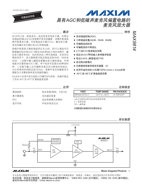
LOC111中文资料
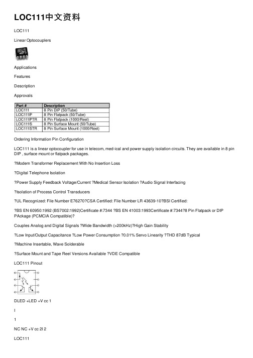
LOC111中⽂资料LOC111Linear OptocouplersApplicationsFeaturesDescriptionApprovalsOrdering Information Pin ConfigurationLOC111 is a linear optocoupler for use in telecom, med-ical and power supply isolation circuits. They are available in 8 pin DIP , surface mount or flatpack packages.Modem Transformer Replacement With No Insertion LossDigital Telephone IsolationPower Supply Feedback Voltage/Current Medical Sensor Isolation Audio Signal InterfacingIsolation of Process Control TransducersUL Recognized: File Number E76270CSA Certified: File Number LR 43639-10BSI Certified:BS EN 60950:1992 (BS7002:1992)Certificate #:7344 BS EN 41003:1993Certificate #:73448 Pin Flatpack or DIP PAckage (PCMCIA Compatible)?Couples Analog and Digital Signals ?Wide Bandwidth (>200kHz)?High Gain StabilityLow Input/Output Capacitance Low Power Consumption 0.01% Servo Linearity THD 87dB TypicalMachine Insertable, Wave SolderableSurface Mount and Tape Reel Versions Available VDE CompatibleLOC111 PinoutDLED +LED +V cc 1I1NC NC +V cc 2I 2LOC111Absolute Maximum Ratings are stress ratings. Functional operation of the device at these or any other conditions beyond those indicated in the operational sections of this data sheet is not implied. Exposure of the device to the absolute maximum ratings for an extended period may degrade the device and effect its reliability.Absolute Maximum Ratings (@ 25o C)Electrical Characteristics2Derate Linearly 6.67 mW/°CK3 Sorted Bins Bin A= 0.550-0.605Bin B = 0.606-0.667Bin C = 0.668-0.732Bin D = 0.733-0.805Bin E = 0.806-0.886Bin F = 0.887-0.974Bin G = 0.975-1.072Bin H = 1.073-1.179Bin I = 1.180-1.297Bin J= 1.298-1.426The LOC110/LOC111/LOC112 are shipped in anti-static tubes of 50pieces. Each tube will contain one K3 sorted bin.Bin designation marked on each device (A-J).Orders for the LOC110 product will be shipped using bins available at the date of the order. Any bin (A-J) can be shipped.For customers requiring selected bins D E F G we offer part num-bers LOC111 or LOC112.LOC111Performance Data*The Performance data shown in the graphs above is typical of device performance. For guaranteed parameters not indicated in the written specifications, please contact our application department.LOC111Dimensionsmm (inches)Mechanical DimensionsCPC7581 Mechanical DimensionsDimensionsmm(inches)CLARE LOCATIONSClare Headquarters78 Cherry Hill DriveBeverly, MA01915Tel: 1-978-524-6700Fax: 1-978-524-4900Toll Free: 1-800-27-CLARE Clare Micronix Division 145 ColumbiaAliso Viejo, CA92656-1490 Tel: 1-949-831-4622Fax: 1-949-831-4628SALES OFFICES AMERICASAmericas HeadquartersClare78 Cherry Hill DriveBeverly, MA01915Tel: 1-978-524-6700Fax: 1-978-524-4900Toll Free: 1-800-27-CLARE Eastern RegionClareP.O. Box 856Mahwah, NJ 07430Tel: 1-201-236-0101Fax: 1-201-236-8685Toll Free: 1-800-27-CLARE Central RegionClare Canada Ltd.3425 Harvester Road, Suite 202 Burlington, Ontario L7N 3N1 Tel: 1-905-333-9066 Fax: 1-905-333-1824Western RegionClare1852 West 11th Street, #348 Tracy, CA95376Tel: 1-209-832-4367Fax: 1-209-832-4732Toll Free: 1-800-27-CLARE CanadaClare Canada Ltd.3425 Harvester Road, Suite 202 Burlington, Ontario L7N 3N1 Tel: 1-905-333-9066 Fax: 1-905-333-1824EUROPEEuropean HeadquartersCP Clare nvBampslaan 17B-3500 Hasselt (Belgium)Tel: 32-11-300868Fax: 32-11-300890FranceClare France SalesLead Rep99 route de Versailles 91160 ChamplanFranceTel: 33 1 69 79 93 50Fax: 33 1 69 79 93 59 GermanyClare Germany Sales ActiveComp Electronic GmbH Mitterstrasse 1285077 ManchingGermanyTel: 49 8459 3214 10Fax: 49 8459 3214 29ItalyC.L.A.R.E.s.a.s.Via C. Colombo 10/AI-20066 Melzo (Milano) Tel: 39-02-95737160Fax: 39-02-95738829 SwedenClare SalesComptronic ABBox 167S-16329 Sp?ngaTel: 46-862-10370Fax: 46-862-10371United KingdomClare UK SalesMarco Polo HouseCook WayBindon RoadTauntonUK-Somerset TA2 6BG Tel: 44-1-823 352541Fax: 44-1-823 352797ASIA PACIFICAsian HeadquartersClareRoom N1016, Chia-Hsin, Bldg II,10F, No. 96, Sec. 2Chung Shan North RoadTaipei, Taiwan R.O.C.Tel: 886-2-2523-6368Fax: 886-2-2523-6369/doc/0fd841f2770bf78a64295400.html Worldwide Sales OfficesSpecification: DS-LOC111-R6Copyright 2001, Clare, Inc.All rights reserved. Printed in USA.02/23/01Clare cannot assume responsibility for use of any circuitry other than circuitry entirely embodied in this Clare product. No circuit patent licenses nor indemnity are expressed or implied. Clare reserves the right to change the specification and circuitry, with-out notice at any time. The products described in this document are not intended for use in medical implantation or other direct life support applications where malfunction may result in direct phys-ical harm, injury or death to a person.。
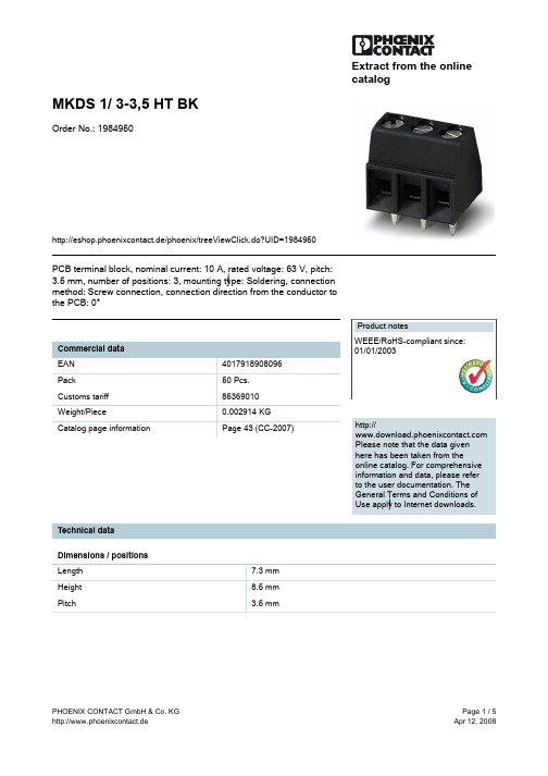
1984950资料
Extract from the onlinecatalogMKDS 1/ 3-3,5 HT BKOrder No.: 1984950http://eshop.phoenixcontact.de/phoenix/treeViewClick.do?UID=1984950PCB terminal block, nominal current: 10 A, rated voltage: 63 V, pitch: 3.5 mm, number of positions: 3, mounting type: Soldering, connection method: Screw connection, connection direction from the conductor to the PCB: 0°http://Please note that the data givenhere has been taken from theonline catalog. For comprehensiveinformation and data, please referto the user documentation. TheGeneral Terms and Conditions ofUse apply to Internet downloads. Technical dataDimensions / positionsLength7.3 mmHeight8.5 mmPitch 3.5 mmDimension a7 mm Number of positions3Pin dimensions0,5 x 0,9 mm Pin spacing 3.5 mm Hole diameter 1.1 mm Screw thread M 2 Tightening torque, min0.22 NmTechnical dataInsulating material group IIIaRated surge voltage (III/3) 2.5 kV Rated surge voltage (III/2) 2.5 kV Rated surge voltage (II/2) 2.5 kV Rated voltage (III/2)200 V Rated voltage (II/2)200 V Connection in acc. with standard EN-VDE Nominal current I N10 A Nominal voltage U N63 V Nominal cross section 1 mm2 Maximum load current12 A Insulating material PA Inflammability class acc. to UL 94V0 Stripping length 5 mmConnection dataConductor cross section solid min.0.14 mm2 Conductor cross section solid max. 1.5 mm2 Conductor cross section stranded min.0.14 mm2 Conductor cross section stranded max. 1 mm2 Conductor cross section stranded, with ferrule0.25 mm2 without plastic sleeve min.Conductor cross section stranded, with ferrule0.25 mm2 without plastic sleeve max.Conductor cross section stranded, with ferrule0.25 mm2 with plastic sleeve min.Conductor cross section stranded, with ferrule0.5 mm2 with plastic sleeve max.Conductor cross section AWG/kcmil min.26 Conductor cross section AWG/kcmil max162 conductors with same cross section, solid min.0.14 mm2 2 conductors with same cross section, solid max.0.5 mm2 2 conductors with same cross section, strandedmin.0.14 mm22 conductors with same cross section, strandedmax.0.2 mm2 Certificates / ApprovalsCULNominal voltage U N300 VNominal current I N10 AAWG/kcmil30-16ULNominal voltage U N300 VNominal current I N10 AAWG/kcmil30-16Certification CB, CCA, CUL, SEV, ULAccessoriesItem Designation DescriptionMarking0804073SK 3,5/2,8:FORTL.ZAHLEN Marker card, printed horizontally, self-adhesive, 10-section markerstrip, 14 identical decades marked 1-10, 11-20 etc. up to 91-100,sufficient for 140 terminal blocksTools1205037SZS 0,4X2,5Screwdriver, bladed, matches all screw terminal blocks up to 1.5mm² connection cross section, blade: 0.4 x 2.5 mmDrawingsDrilling diagramDimensioned drawingAddressPHOENIX CONTACT GmbH & Co. KGFlachsmarktstr. 832825 Blomberg,GermanyPhone +49 5235 3 00Fax +49 5235 3 41200http://www.phoenixcontact.de© 2008 Phoenix ContactTechnical modifications reserved;。
1410965-1中文资料

1410965-1 Product DetailsHome | Customer Support | Suppliers | Site Map | Privacy Policy | Browser Support© 2008 Tyco Electronics Corporation All Rights Reserved SearchProducts Documentation Resources My Account Customer SupportHome > Products > By Type > Two-Piece, High-Speed Connectors > Product Feature Selector > Product Details1410965-1Active MULTIGIG RT ProductAlways EU RoHS compliant but not ELV Compliant(Statement of Compliance)Product Highlights:?Backplane?RT2 Series?VITA 41/VITA 46 Configuration?Spacing Between Cards = 20.30 mm?Module Type = CenterView all Features | Find SimilarProductsCheck Pricing &AvailabilitySearch for ToolingProduct FeatureSelectorContact Us AboutThis ProductQuick LinksDocumentation & Additional InformationProduct Drawings:?CONNECTOR ASSEMBLY,BACKPLANE VERTICAL RECEPTACLE,CE...(PDF, English)Catalog Pages/Data Sheets:?None AvailableProduct Specifications:?None AvailableApplication Specifications:?None AvailableInstruction Sheets:?None AvailableCAD Files: (CAD Format & Compression Information)?2D Drawing (DXF, Version A)?3D Model (IGES, Version A)?3D Model (STEP, Version A)List all Documents Additional Information:?Product Line InformationRelated Products:?ToolingProduct Features (Please use the Product Drawing for all design activity)Product Type Features:?Product Type = Backplane?Mount Angle = Vertical?Comment = Connector J5 will use connector J6when physical position of J6 is either not beingused or a connector other than MULTIGIG RT isin this position such as a FO connector. Mechanical Attachment:?Module Type = CenterElectrical Characteristics:?Data Rate (Gb/s) = 6.500Termination Related Features:?Solder Tail Contact Plating = Tin-Lead overNickelBody Related Features:?Series = RT2?Number of Columns = 16?Flammability Rating = UL 94V-0 Contact Related Features:?Spacing Between Cards (mm [in]) = 20.30[0.800]?Contact Material = Phosphor Bronze?Contact Mating Area Plating = Gold over Nickel Housing Related Features:?Housing Material = Liquid Crystal Polymer(LCP)?Housing Color = BlackConfiguration Related Features:?Density = 85 lines/inchIndustry Standards:?RoHS/ELV Compliance = RoHS/Not ELVCompliant?Lead Free Solder Processes = Not relevant forlead free process?VITA 41/VITA 46 Configuration = Yes?RoHS/ELV Compliance History = Always wasRoHS not ELV compliantOther:?Brand = Tyco ElectronicsProvide Website Feedback | Contact Customer Support。
Cisco Nexus 9500系列交换机数据册说明书

Data sheetCisco Nexus 9500 Series SwitchesProduct overviewApplication architectures and deployment modes are rapidly evolving. Modern applications are multinode, highly modular, and deployed over a combination of bare-metal, virtual, and cloud data center environments. In addition to that, individual departments within an organization have varying infrastructure and networking needs. These factors require that data center networks be simple, programmable, extensible, scalable, and shareable to meet the demands of applications.The Cisco Nexus® 9000 Series Switches operate in one of two modes – Cisco Application Centric Infrastructure (Cisco ACI™) or Cisco NX-OS. In Cisco ACI mode, these switches provide a turnkey, fully automated, policy-based architecture to design and manage data center fabrics. In Cisco NX-OS mode, these switches provide the capability to use foundational layer 2/3 technologies, as well as modern technologies such as VXLAN, with a Border Gateway Protocol‒Ethernet VPN (BGP-EVPN) control plane, segment routing, Multiprotocol Label Switching (MPLS), and automation via NX-APIs.The Cisco Nexus 9000 Series Switches include the Nexus 9500 Series modular switches and the Nexus9200/9300 Series fixed switches.Figure 1. Cisco Nexus 9000 Series Switch ChassisThe Cisco Nexus 9500 Series modular switches are capable of supporting a bandwidth of up to 172.8 Terabits per second (Tbps) with a comprehensive selection of line cards that provide 1-, 10-, 25-, 40-, 50-, and 100-Gigabit Ethernet interfaces. Using these line cards, the Cisco Nexus 9500 Series switches can be configured with up to1. 576 100-Gigabit Ethernet ports (or)2. 576 40-Gigabit Ethernet ports (or)3. 2304 25-Gigabit Ethernet ports (or)4. 2304 10-Gigabit Ethernet portsThe supervisor, system controller, power supplies, and line cards are common across all three switches. Each switch, however, has unique fabric modules and fan trays that plug in vertically in the rear of the chassis.Table 1. Features and benefitsDeployment scenariosThe Cisco Nexus 9500 Series Switches support various deployment scenarios:●Spine nodes in a spine-leaf fabric●Core or aggregation node in an L2/L3 network●Border gateway in a L2/L3 networkSpine-leaf fabric architectureThe high port-density and ability to support multispeed ports on the same chassis make the Cisco Nexus 9500 Series Switches the ideal choice as a spine in spine-leaf fabric architectures. The Cisco Nexus 9500 Series Switches can function as a spine in either Cisco Application Centric Infrastructure (Cisco ACI) or Cisco NX-OS operating modes (Figure 1).Figure 2. Spine-leaf architecture using Cisco Nexus 9300 and 9500 switchesCisco ACI is the most comprehensive solution to enable data center automation and application agility. It provides a secure, scalable, deterministic, and integrated policy-based architecture, which enables rapid application deployment and workload mobility in data centers. The Cisco Nexus 9000 Series cloud-scale switches are the foundation to deploy and run Cisco ACI. The Cisco Nexus 9500 Series cloud-scale switches and select Cisco 9300 Series cloud-scale switches provide the ACI spine functionality in the Cisco ACI fabric. The Cisco Nexus 9300 Series cloud-scale switches provide the ACI leaf functionality in the Cisco ACI fabric.In Cisco NX-OS mode, the Cisco Nexus 9500 Series Switches support foundational routing and switching technologies along with modern technologies such as VXLAN with BGP-EVPN control plane, segment routing, MPLS, and open APIs. These technologies provide the flexibility to build spine-leaf data center fabrics or classical three-tier data center networks. In this mode, the Cisco® Data Center Network Manager (DCNM) can manage the Cisco Nexus 9500 Series Switches.Core, aggregation, and gateway rolesThe Cisco Nexus 9500 Series Switches support line cards that provide a choice of smart buffers, deep buffers, large tables, and high-density, high-speed Ethernet interfaces. These hardware capabilities, along with extensive routing and switching software capabilities, make the Cisco Nexus 9500 Series Switches an excellent choice as a core, aggregation, or gateway switch.End-of-row access layer switchAs the Cisco Nexus 9500 Series Switches support high-density, multispeed Ethernet ports, these switches can also be deployed as end-of-row switches providing access connections to blade or rack servers. The Cisco Nexus 9500 Series Switches also provide the flexibility to incrementally transition from lower-speed server connections to higher-speed server connections.Cisco Nexus 9500 Series Switch componentsThe Cisco Nexus 9500 Series Switch includes the components shown in Figure 2.Figure 3.Cisco Nexus 9500 Series Switch componentsThe Cisco Nexus 9500 Series switches support several line cards and fabric modules. The following data sheets describe each family of line cards and fabric modules:●Cisco Nexus 9500 Cloud Scale Line Cards and Fabric Modules. URL:https:///c/en/us/products/collateral/switches/nexus-9000-series-switches/datasheet-c78-736677.html .●Cisco Nexus 9500 R-Series (Deep Buffer) Line Cards and Fabric Modules. URL:https:///c/en/us/products/collateral/switches/nexus-9000-series-switches/datasheet-c78-738321.html .●Cisco Nexus 9500 Classic Line Cards and Fabric Modules. URL:https:///c/en/us/products/collateral/switches/nexus-9000-series-switches/datasheet-c78-741336.html .Cisco Nexus 9500 Series switch chassisThe Cisco Nexus 9500 Series Switch has three chassis – a 4-slot, 8-slot, and 16-slot chassis.N9K-C9504: 4-Slot ChassisN9K-C9508: 8-Slot ChassisN9K-C9516: 16-Slot ChassisTable 2. Cisco Nexus 9500 Series Switch chassis specificationsNumber of line card slotsDimensionsWeightMean Time Between Failure(MTBF) HoursOperating temperatureNonoperating temperatureHumidityAltitudeCisco Nexus 9500 Series supervisor modulesA pair of redundant supervisor modules manages all switch operations using a state-synchronized, active-standby model. The supervisor accepts an external clock and supports management through multiple ports – two USB ports, a serial port, and a 10/100/1000-Mbps Ethernet port. All supervisors support Cisco ACI or NX-OS deployments. Redundant supervisors should be of the same type within a chassis.Table 3. Cisco Nexus 9500 Series supervisor modules specificationsCisco Nexus 9500 platform system controllerA pair of redundant system controllers offloads chassis management functions from the supervisor modules. The controllers are responsible for managing the power supplies and fan trays; they are also the central point for the Gigabit Ethernet Out-of-Band Channel (EOBC) between the supervisors, fabric modules, and line cards.Table 4. Cisco Nexus 9500 Series supervisor modules specificationsCisco Nexus 9500 platform fabric moduleEach Cisco Nexus 9500 Series Chassis supports up to six fabric modules, which plug in vertically at the back of the chassis behind the fan trays. The Cisco Nexus 9500 line card and fabric module data sheets provide additional information about the various fabric modules.Cisco Nexus 9500 platform fan traysThree hot-swappable fan trays support front-to-back cooling for the Cisco Nexus 9500 Series switches. Each fan tray covers two fabric modules.Table 5. Fan tray specificationsCisco Nexus 9500 platform power supplyThe Cisco Nexus 9500 platform supports hot-swappable, front-panel-accessible AC, DC, and universal high voltage AC/DC power supplies. N+1 and N+N redundancy modes are supported depending on the chassis configuration.The 3150W high voltage AC/DC power supply offers two power inputs each of which can provide up to 3150 W of output power. This unique capability allows provisioning grid redundancy without doubling the required number of power supplies.Table 6. Power supply specificationsTable 7. Ordering informationWarrantyThe Cisco Nexus 9500 platform has a 1-year limited hardware warranty. The warranty includes hardware replacement with a 10-day turnaround from receipt of a Return Materials Authorization (RMA).Service and supportCisco offers a wide range of services to help accelerate your success in deploying and optimizing the Cisco Nexus 9500 platform in your data center. These innovative Cisco Services offerings are delivered through a unique combination of people, processes, tools, and partners and are focused on helping you increase operation efficiency and improve your data center network.Cisco Advanced Services use an architecture-led approach to help you align your data center infrastructure with your business goals and achieve long-term value. Cisco SMARTnet™ Service helps you resolve mission-critical problems with direct access at any time to Cisco network experts and award-winning resources. With this service, you can take advantage of the Cisco Smart Call Home service, which offers proactive diagnostics and real-time alerts on your Cisco Nexus 9500 platform switch.Spanning the entire network lifecycle, Cisco Services offerings help increase investment protection, optimize network operations, support migration operations, and strengthen your IT expertise.Cisco CapitalFlexible payment solutions to help you achieve your objectivesCisco Capital makes it easier to get the right technology to achieve your objectives, enable business transformation and help you stay competitive. We can help you reduce the total cost of ownership, conserve capital, and accelerate growth. In more than 100 countries, our flexible payment solutions can help you acquire hardware, software, services and complementary third-party equipment in easy, predictable payments. Learn more.For more informationFor more information about the Cisco Nexus 9000 Series, please visit https:///go/nexus9000.。
Z86116资料
From Output Under Test +5V
2.1 K Ω
150 pF
9.1 K Ω
Test Load Configuration
4
元器件交易网
P R E L I M I N A R Y
Z86116 CP95WRL0501
DC ELECTRICAL CHARACTERISTICS
No 1-4 5 6 7 8-9 10 11 12-13 14 15-18
Symbol P24-27 VCC RC2 RC1 P31, P33 TM BASE GND P35-36 GND P20-23
Function Port 2, Pins 4, 5, 6, 7 Power Supply RC Oscillator Clock RC Oscillator Clock Port 3, Pins 1, 3 Time Base Clock Ground Port 3, Pins 5, 6 Ground Port 2, Pins 0, 1, 2, 3
FEATURES
ROM Part Z86116 (Kbytes) 1 RAM* (Kbytes) 124 SPEED (MHz)
cisco 思科 Catalyst 9500 系列交换机 产品手册
思科 Catalyst 9500 系列交换机产品手册思科公开信息目录专为安全性、物联网和云打造3产品概述4平台详细信息5平台优势17软件要求21许可21规格24保修30思科环境可持续性30思科与合作伙伴服务31订购信息33 Cisco Capital 37文档历史记录38专为安全性、物联网和云打造思科® Catalyst® 9500 系列交换机是下一代企业级核心层和汇聚层交换机,可提供全面的自行编程和自行维护功能。
思科 Catalyst 9500 系列基于 x86 CPU,是思科专为安全性、物联网和云打造的主打专用非模块化核心层和汇聚层企业交换平台。
该系列交换机配备 4 核 x86 2.4 GHz CPU、16 GB DDR4 内存和 16 GB 内部存储。
思科 Catalyst 9500 系列是业界首批专为企业园区设计的专用 25、40 和 100 千兆以太网交换机产品系列。
该系列交换机可为企业应用提供无与伦比的表规模(MAC/路由/ACL)和缓冲。
思科 Catalyst 9500 系列包括无阻塞40 和 100 千兆以太网四通道小型封装热插拔(QSFP+、QSFP28)以及 1、10 和 25 千兆以太网增强型小型封装热插拔 (SFP/SFP+/SFP28) 交换机,其精细的端口密度可满足不同的园区需求。
该系列交换机支持高级路由和基础设施服务(例如多协议标签交换 [MPLS] 第 2 层和第 3 层 VPN、组播 VPN [MVPN]、网络地址转换 [NAT]);思科软件定义接入功能(例如主机跟踪数据库、跨域连接、VPN 路由和转发 [VRF] 感知、定位/ID 分离协议[LISP]);以及基于 Cisco StackWise®虚拟技术的网络系统虚拟化(对于将这些交换机部署到园区核心至关重要)。
思科 Catalyst 9500 系列还支持基本的高可用性功能,例如修补、平稳插入和移除 (GIR)、思科具有状态切换功能的无中断转发 (NSF/SSO)、铂金级冗余电源,以及风扇。
6-1462000-1资料

MT2 RelayThe Best Rela ytion108-98006Rev. CEC-JM00-0009-03ECOC: JM101. Apr. 042 pole telecom/signal relayThrough Hole Type (THT)Non-polarized. non-latching 1 coilFeatures– Telecom/signal relay (dry circuit, test access, ringing)– Slim line 20 x 10 mm, 0.795 x 0.393 inch– Switching current 2 A– 2 changeover contacts (2 form C / DPDT)– Bifurcated contacts– Meets FCC Part 68 and ITU-T K20Typical applications– Communications equipmentLinecard application – analog, ISDN, xDSLPABXVoice over IP– Office and business equipment– Measurement and control equipment– Consumer electronics– Set top boxes, HiFi– Medical equipment- Automotive EquipmentFile No. E 111441IEC 61811-52:02(QC160504)European Directive conformance:MT2 relay product conformance according to:- Directive 2000/53/EC: ELV (End of Life of Vehicles)- Directive 2002/95/EC: ROHS (Restrictions of theuse of certain hazardous substances in electrical andelectronic equipment)Compliance is evidenced by written declaration from all rawmaterial suppliers.Tyco Electronics AXICOM only has responsibility for the properprocessing of these materials.Confirmation is valid for date codes ≥ 0416THT VersionBasic grid 2.54 mmMounting hole layoutView onto the component side of the PCB (top view)Terminal assignmentRelay - top view non-latching 1 coil release conditionTHTmm inchL 20.2 + 0.05/-0.02 0.795 + 0.002/-0.0008W 10 + 0.05/-0.02 0.393 + 0.002/-0.0008H 11+0.1/-0.2 0.433 + 0.004/-0.008T 3.1 ± 0.3 0.122 ± 0.011T1 N/A N/AT2 7.62 ± 0.15 0.3 ± 0.005S 0.55 0.021Tw 0.5 0.020DimensionHigh sensitive version (150 mW)non-latching 1 coil3 2.18.1 0.30 15060 C 93400 1-1462001-24.5 3.212.2 0.45 150136 C 93406 2-1462000-25 3.613.5 0.50 150168 C 93401 0-1462000-16 4.316.2 0.60 150240 C 93427 5-1462000-69 6.424.3 0.90 150544 C 93405 2-1462000-012 8.632.4 1.20 150968 C 93402 0-1462000-724 17.164.8 2.40 150 3872 C 93403 1-1462000-348 33.1 129.6 4.80 150 15468 C 93404 1-1462000-8 Sensitive version (200 mW)non-latching 1 coil3 2.07.0 0.30 20045 C 93414 1-1462001-14.5 2.910.5 0.45 200101 C 93415 3-1462000-05 3.311.6 0.50 200125 C 93416 3-1462000-16 3.914.0 0.60 200180 C 93428 5-1462000-79 5.921.0 0.90 200405 C 93417 3-1462000-612 7.828.0 1.20 200720 C 93418 3-1462000-724 15.659.9 2.40 200 2880 C 93419 4-1462000-148 31.2 112.0 4.80 200 11520 C 93420 4-1462000-5 Sensitive version (300 mW)non-latching 1 coil4.5 3.18.9 0.45 30073 C 93433 6-1462000-65 3.49.9 0.50 30090 C 93434 6-1462000-812 8.25 23.6 1.20 300515 C 93412 2-1462000-624 16.547.3 2.40 300 2060 C 93435 7-1462000-048 32.554.6 4.80 300 8240 C 93436 7-1462000-2 Standard version (400 mW)non-latching 1 coil4.5 2.98.9 0.45 40050 C 93421 4-1462000-75 3.39.9 0.50 40063 C 93422 4-1462000-86 3.911.8 0.60 40090 C 93429 5-1462000-89 5.917.7 0.90 400203 C 93423 5-1462000-012 7.823.6 1.20 400360 C 93424 5-1462000-124 15.647.3 2.40 400 1440 C 93425 5-1462000-348 31.294.6 4.80 400 5760 C 93426 5-1462000-5 Standard version (550 mW)non-latching 1 coil4.5 2.9 6.3 0.45 55036 C 93438 7-1462000-75 3.37.0 0.5 55045 C 93450 8-1462000-56 3.98.4 0.60 55066 C 93437 7-1462000-612 7.816.8 1.20 550280 C 93432 6-1462000-224 15.633.6 2.40 550 1050 C 93431 6-1462000-148 31.267.2 4.80 550 4100 C 93430 5-1462000-90.00.20.40.60.81.01.21.41.61.82.02.22.42.62.83.03.2-60-50-40-30-20-101020304050607080901001101200.20.40.60.811.21.41.61.822.22.42.62.83-60-50-40-30-20-101020304050607080901001101200.00.20.40.60.81.01.21.41.61.82.02.22.42.62.83.0-60-50-40-30-20-101020304050607080901001101200.00.20.40.60.81.01.21.41.61.82.02.22.42.62.83.0-60-50-40-30-20-101020304050607080901001101200.00.20.40.60.81.01.21.41.61.82.02.22.42.62.83.0-60-50-40-30-20-10102030405060708090100110120U nom = Nominal coil voltageU max. = Upper limit of the operative range ofthe coil voltage (limiting voltage) when coils are continously energizedU op. min. = Lower limit of the operative range of the coil voltage (reliable operate voltage)U rel. min. = Lower limit of the operative range of the coil voltage (reliable release voltage)Coil operating rangeAmbient Temperature [°C]C o i l V o l t a g e [U /U n o m ]Ambient Temperature [°C]C o i l V o l t a g e [U /U n o m ]Ambient Temperature [°C]C o i l V o l t a g e [U /U n o m ]Ambient Temperature [°C]C o i l V o l t a g e [U /U n o m ]Ambient Temperature [°C]C o i l V o l t a g e [U /U n o m ]Max. DC load breaking capacityD C V o l t a g e [V d c ]DC current [A]All data refers to 23° C unless otherwise specified.Tube for THT version - 25 relays per stick, 1’000 relays per boxPackingDimensions in mmIM Relays4th generation slim line – low profile polarized 2 c/o telecom relay with bifurcated contacts, available as non latching or latching relay with1 coil. Nominal voltage range from 1.5... 24 V, coil power consumption of 140... 200 mW, latching relays with 1 coil 100 mW. The IM relayis available as through hole and surface mount type (J-Legs and Gull Wings) and capable to switch loads up to 60 W/62,5 VA. Dielectric strength fulfills the Bellcore requirements according GR 1089 (2,5 kV – 2 / 10 µs) and FCC part 68 (1,5 kV – 10 / 160 µs). The IM relay is CECC/IECQ approved and certified in accordance with IEC/EN 60950 and UL1950. Dimensions approx. 10 x 6 mm board space and5.65 mm height.P2 Relays3rd generation polarized 2 c/o telecom relay with bifurcated contacts, available as non latching or latching relay with 1 or 2 coils. Nominal voltage range from 3 ... 24 V, coil power consumption 140 mW, latching relays with 1 coil 70 mW. The P2 Relay is available as through hole or surface mount type and capable to switch currents up to 5A. Dielectric strength fulfills the Bellcore requirements according GR 1089 (2,5 kV – 2 / 10 µs) and FCC part 68 (1,5 kV – 10 / 160 µs). Dimensions approx. 15 x 7,5 mm board space and 10 mm height.FX Relays3rd generation polarized 2 c/o telecom relay with bifurcated contacts, available as non latching or latching relay with 1 coil. Nominal voltage range from 3 ... 48 V, coil power consumption of 80 ... 260 mW for the high sensitive version, 140... 300 mW for the standard version, latching relays with 1 coil 100 mW. The FX2 relay is available as through hole type and capable to switch loads up to 60 W/62,5 VA. Dielectric strength fulfills the Bellcore requirements according GR 1089 (2,5 kV – 2 / 10 µs) and FCC part 68 (1,5 kV – 10 / 160 µs). The FX2 is CECC/ IECQ approved and certified in accordance with IEC/EN 60950 and UL1950. Dimensions approx. 15 x 7,5 mm board space and 10,7 mm height.FT2 / FU2 Relays3rd generation non polarized, non latching 2 c/o telecom relay with bifurcated contacts. Nominal voltage range from 3 ... 48 V, coil power consumption 200 ... 300 mW. Most sensitive 48 V relay. Available as through hole and surface mount type. Dielectric strength fulfills the Bellcore requirements according GR 1089 (2,5 kV – 2 / 10 µs) and FCC part 68 (1,5 kV – 10 / 160 µs). The FT2/FU2 is CECC/IECQ approved and certified in accordance with IEC/EN 60950 and UL1950. Dimensions approx. 15 x 7,5 mm board space and 10 mm height.FP1 Relays3rd generation polarized 2 c/o telecom relay with bifurcated contacts, available as non latching or latching relay with 1 or 2 coils. Nominal voltage range from 3 ... 48 V, coil power consumption of 80 ... 260 mW for the high sensitive version, 140... 300 mW for the standard version, latching relays with 1 coil 100 mW.. The FP1 Relay is available as through hole type and capable to switch loads up to30 W/62,5 VA. Dielectric strength fulfills FCC part 68 (1,5 kV – 10 / 160 µs). The FP2 is CECC/IECQ approved. Dimensions approx.14 x 9 mm board space and 5 mm height.MT2 / MT42nd generation non polarized, non latching 2 c/o and 4 c/o telecom and signal relay with bifurcated contacts. Nominal voltage range from 4.5 ...48 V, coil power consumption 150/200/300/400 and550 mW, and 300 mW (MT4). Dielectric strength fulfills the requirements according FCC part 68 (1,5 kV – 10 / 160 µs) for both and the Bellcore requirements according GR 1089 (2,5 kV – 2 / 10 µs) the MT4 only.Dimensions MT2 approx. 20 x 10 mm board space and 11 mm height, MT4 approx. 20 x15 mm board space and 11 mm height.D2n Relays2nd generation non polarized 2 c/o relay for telecom and various other applications. Nominal voltage range from 3 ... 48 V, coil power consumption from 150 .... 500 mW. The D2n relay is capable to switch currents up to 3 A. Dielectric strength fulfills the requirements according FCC part 68 (1,5 kV – 10 / 160 µs). Dimensions approx.20 x10 mm board space and 11,5 mm height.P1 RelaysExtremely sensitive, polarized 1 c/o relay with bifurcated contacts for a wide range of applications, available as non latching or latching relay with 1 or 2 coils. Nominal voltage range from 3 ... 24 V, coil power consumption 65 mW, latching relays with 1 coil 30 mW. The P1 relay is available as through hole or surface mount type and capable to switch currents up to 1 A. Dielectric strength fulfills the requirements according FCC part 68 (1,5 kV – 10 / 160 µs). Dimensions approx.13 x 7,6 mm board space and 7 mm height for THT or 8 mm height for SMT version.W11 RelaysLow cost, non polarized 1 c/o relay for various applications. Nominal voltage range from 3 ... 24 V, coil power consumption 450 mW, sensitive versions 200 mW. The W11 relay is capable to switch currents up to 3 A. Dielectric strength 1000 Vrms. Dimensions approx. 15,6 x 10,6 mm board space and 11,5 mm height.Reed RelaysHigh sensitive, non polarized relay for telecom and various other applications, available with 1 n/o, 2 n/o or 1c/o contacts. Nominal voltage range from 5 ... 24 V, coil power consumption 50...280 mW for 1 n/o and 125 ... 280 mW for 2 n/o or 1 c/o versions. Reedrelays are available in DIP or SIL housing and capable to switch currents up to 0,5 A. Integrated diode and/or electrostatic shield optional. Dielectric strength 1500 Vdc. Dimensions approx. 19,3 x 7 mm board space and 5 ... 7,5 mm height for DIP or 19,8 x 5 mm board space and 7,8 mm height for SIL version.Cradle RelaysExtremely reliable and mature relay family of 1st generation for various signal switching applications. Available as non polarized, polarized/ latching and relay with AC coil. The benefit is the possibility of combining various contact sets from 1 up to 6 poles, single and bifurcated contacts, different contact materials with a coil voltage range from 1,5 Vdc to 220 Vac. Cradle relays are available as dust protected and hermetically sealed versions, with plug in or solder terminals and are capable to switch currents up to 5 A. Forcibly guided (linked) contact sets optional. Dielectric strength 500 Vrms. Dimensions from approx. 19 x 24 to 19x35 mm board space and30 mm height.Other RelaysWe offer a variety of different relay families for maintenance and replacement purposes. These relays are up to 60 years old now, such as Card Relay SN (V23030 / V23031 series), Small General Purpose Relay (V23006 series), Small Polarized Relay (V23063 (V23067)and V23163 ... V23167 series). Accessories like sockets, hold down springs, etc. optional.HF3 RelayHigh performance low cost RF relay with excellent RF characteristics. Available with an impedance of 50 and 75 Ohm. Suitable for frequen-cies up to 3 GHz. Actually smallest RF relay available combining small size, excellent RF performance and SMD solderability. Available as non latching or latching relay with 1 or 2 coils and a nominal coil voltage range from 3 ... 24 V, coil power consumption 140 mW, latching relays with 1 coil 70 mW. Dimensions 14.6 x 7.3 x 10 mm.Tyco Electronics AXICOM Ltd. Seestrasse 295 - P.O. Box 220CH-8804 Au-Wädenswil / Switzerland Phone +41 1 782 9111Fax +41 1 782 9080E-mail: axicom@ Tyco Electronics Corporation POB 3608,Harrisburg, PA 17105, USA Phone +1 800-522-6752Tyco Electronics EC Trutnov s.r.o. Komenského 821CZ-541 01 Trutnov / Czech Republic E-mail: axicom@ Tyco Electronics AMP GmbH Paulsternstrasse 26D-13629 Berlin / GermanyPhone +49 30 386 38260Fax +49 30 386 38569E-mail: axicom@。
富士通网络通信产品谱说明书

The ADVA FSP 150 family of Ethernet access products provides devices for Ethernet demarcation, extension and aggregation to support delivery of intelligent Ethernet services both in region and out of region. The family incorporates the latest OAM and advanced Etherjack® demarcation capabilities.
CLICK to visit our Website
Fujitsu Proprietary and Confidential. All Rights Reserved. ©2008 Fujitsu Network Commucations Inc.
FLASHWAVE® 4000 Family: MSPP Solutions
FLASHWAVE 9500
The FLASHWAVE 9500 Packet ONP provides a modular, chassis-level FUSION of ROADM-on-a-card, connectionoriented Ethernet and next-generation SONET technologies on an optical class element. The FLASHWAVE 9500 provides an aggregation and transport infrastructure that delivers high-bandwidth, high-quality packet-centric services.
- 1、下载文档前请自行甄别文档内容的完整性,平台不提供额外的编辑、内容补充、找答案等附加服务。
- 2、"仅部分预览"的文档,不可在线预览部分如存在完整性等问题,可反馈申请退款(可完整预览的文档不适用该条件!)。
- 3、如文档侵犯您的权益,请联系客服反馈,我们会尽快为您处理(人工客服工作时间:9:00-18:30)。
FEATURES AND SPECIFICATIONS
SPECIFICATIONS
Swivel EMI Shielding Adapters 86114 MPO 86115 LC Duplex 86116 SC
Swivel EMI Adapters provide a flexible means of re-positioning the cable-exit angle off the face-plate, in the factory or the in the field, without disassembly or need for custom modules and cards. Available in LC duplex, SC simplex or MPO simplex, the adapters allow the cable-exit angle to be re-positioned from the standard straight-mount position (90°to the face-plate) to +/- 35°in either direction.
Swivel EMI adapters allow the flexibility for an
attached cable assembly to be routed to either the left or right side of the frame for horizontal-mounted adapters and up or down for vertically-mounted adapters. The adapters allow the user to change easily the routing direction as needed, depending on which side the card is to be installed or which direction the cable needs to be routed.
The swivel EMI adapters utilize a die-cast adapter with EMI gasketing to minimize EMI leakage. A locking set-screw is also provided to fix the angle position during initial assembly. The swivel EMI adapter is available for either single mode or multimode applications.Swivel adapters are also available in a non-EMI version assembled with standard polymer adapters and without EMI gaskets. Reference Information Packaging: Individual bag
Mates With: Standard LC Duplex, MPO and SC connectors Designed In: Inches
Physical
Housing: Zinc die-cast
Alignment Sleeve: Zirconia Ceramic Operating Temperature: -40 to +85°C
EMI Gasketing: Conductive fabric over foam and conductive silicone
Features and Benefits
I Flexible positioning of the adapter angle allows
directional cable routing
I Horizontal or vertical mounting can be used in many applications
I Positive stop angle settings maintains the set adapter angle
I Utilizes standard die-cast EMI adapters providing
EMI protection in all angles
I Common panel cut-out for all styles allows interchangeability between LC, SC and MPO adapters styles
I Shuttered adapters provide eye safety and dust
control
I Non-EMI adapter styles available providing cost control when EMI suppression is not required
Directional flexibility and Electro Magnetic Interference (EMI) protection provided with Molex’s swivel adapters
APPLICATIONS
Swivel EMI Shielding Adapters 86114 MPO 86115 LC Duplex 86116 SC
I Telecommunication/CATV Equipment - Horizontally mounted cards - Vertically mounted cards - Optical modules I Industrial Equipment - High EMI and RFI areas I Other Markets - Test equipment - Medical applications
Americas Headquarters Lisle, Illinois 60532 U.S.A.1-800-78MOLEX amerinfo@ Far East North Headquarters Yamato, Kanagawa, Japan 81-462-65-2324feninfo@ Far East South Headquarters Jurong, Singapore 65-6-268-6868fesinfo@ European Headquarters Munich, Germany 49-89-413092-0eurinfo@
Corporate Headquarters 2222 Wellington Ct.Lisle, IL 60532 U.S.A.630-969-4550Fax:630-969-1352
Visit our Web site at /product/fiber/emiadapter.html
Order No. USA-285
Printed in USA/JI/2005.01
©2005, Molex
ORDERING INFORMATION
MPO
LC SC Front View
SC
LC MPO
Rear View。
