JANS1N4576AUR-1中文资料
1N系列二极管
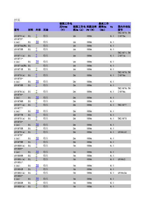
250μ 250μ 250μ
250μ 250μ
250μ 250μ 250μ
250μ 250μ
250μ 250μ 250μ
250μ 250μ
250μ 250μ 250μ
250μ
400m
6.4
2m
400m
6.4
4m
400m
6.4
4m
400m
4m
400m
4m
400m
6.4 6.4 6.4 1N4612
4m
400m
4m
400m
4m
400m
6.4 6.4 6.4 1N4612A
4m
400m
6.4
4m
400m
6.4
4m
400m
6.4
1N4583-
1(A1)
Si 30 稳压
1N4583B Si 7 稳压
)
Si 7
稳压 稳压
1N4616DUR1 Si
1N4617(-1) Si 7
1N4617C(C1
)
Si 7
稳压 稳压
稳压
1N4617CUR1 Si
1N4617D(D1
)
Si 7
稳压 稳压
1N4617DUR1 Si
1N4618(-1) Si 7
1N4618C(C1
)
Si 7
稳压 稳压
稳压
4m 4m 4m
3.6 3.6
3.6 3.6 3.9 MZ4622
3.9 3.9
3.9 3.9 4.3 MZ4623
n457资料
&RQWDFW &RQYHQRU ,62,(& -7& 6& :* 0U (0HODJUDNLV $FKDUQRQ .DWR 3DWLVVLD $7+(16 ± *5((&( 7HO )D[ (PDLO HHP#HORWJU
SOURCE : PROJECT: STATUS :
ITTF JTC 1.02.20.13 The attached table of replies indicates that this DIS has been approved. In accordance with ResolutionM07.24 adopted at the 7WK SC 2 plenary meeting held in Crete, Greece, 1997-07-08/09, the project editor is requested to prepare a disposition of comment report and a revised text For SC 2 consideration and action
元器件交易网
,62,(&-7&6&:*1
元器件交易网
,62,(&-7&6&:*1
元器件交易网
,62,(&-7&6&:*1
元器件交易网
,62,(&-7&6&:*1
元器件交易网
,62,(&-7&6&:*1
Date : 1998-04-15
,62,(&-7&6&:* ELWDQGELWFRGHVDQGWKHLUH[WHQVLRQ 6(&5(7$5,$7(/27
45714中文资料

45911, 45912 P ower andSignal45719, 45714 Power Only 45845, 45844 Signal OnlySPECIFICATIONS ORDERING INFORMATIONFeatures and Benefits n L ow-profile design allows high current transfer in narrow spaces n M ates to a 1.57mm (0.62”) PCB card edge or bus bar n R ated for current interruption hot-plugging requirements n R ugged power and signal contacts reduce the potential for stubbing or damageReference Information Packaging: Tray UL File No.: E29179 CSA File No.: LR19980 TUV: R 72042763Designed In: MillimetersElectricalVoltage: 250V max in standard contact loading (Higher voltages may be accommodated through special contact loading – contact Molex)Current (at 30°C Temperature rise): Power – 40.0A max. Signal – 3.0A max.Contact Resistance (per contact):Initial End of LifePower (milliohms) – 0.5 0.6 max change Signal (milliohms) – 6.24 15 max change Dielectric Withstanding Voltage: 1500V Insulation Resistance: 5000 Megohms min.Current interruption:Power – 40.0A and 50V DC n 2 isolated power contacts or 8 signal contacts per housing segment n A vailable in 2, 3, and 4 segment versions n P ress-fit or solder tail PCB mounting n E nd-to-end stackable to accommodate additional circuit counts on card edgeMechanicalMating Force (max per contact): Power Contacts – 8.87N (2.0 lb) Signal Contacts – 1.4N (0.31 lb)Un-mating Force (max per circuit): Power Contacts – 4.4N (1.0 lb) Signal Contacts – 0.14N (0.031 lb) Durability: 50 cycles Physical Housing: LCP Contact:Power Contacts - Copper Alloy Signal Contacts – Copper Alloy Plating:Contact Area — Select Gold Solder Tail Area — Tin Underplating — Nickel Flammability Rating: UL 94V-0DocumentsSales Drawings: SD-45714-XXXX, SD-45719-XXXX, SD-45844-XXXX, SD-45845-XXXX, SD-45911-XXXX, SD-45912-XXXXProduct Specs: PS-45719-001Connector Series DescriptionPress-Fit Series*Solder Tail Series*Number of SegmentsNumber of Contacts per SegmentSolder Tail Pin Lengths Power only 4571445719 2 to 42 3.19 and 4.33mm Signal only 4584545844 2 to 48 3.19 and 4.33mm Power and Signal45912459112 to 42 Power or 8 Signal3.19 and4.33mm*Complete part numbers can be found at /link/ext-power.htmlThe EXTreme PowerEdge™ Connector incorporates proven Molex design elements of high-performance terminal contacts with redundant interface points for optimum mating of double-sided card edge gold fingers. EXTreme PowerEdge™ offers 40.0A rating per contact, and 157.0 A per inch of PC board real estate. It is an excellent low profile power card edge interface for applications where rugged single piece mating to a cardedge or bus bar is needed and where space is at a premium. EXTreme PowerEdge™ is available in power only, signal only, and power/signal combinations for design flexibility.Current (Amps)706050403020100T -R i s e - (D e g °C )EXTreme PowerEdge™, Dual SidedT-Rise Current Chart1086420-2-4-6EXTreme PowerEdge™ Connector System, DurabilityCumulative Percentage (%)0 10 20 30 40 5060 70 80 90 100C h a n g e i n R e s i s t a n c e (D m V )/link/ext-power.htmlOrder No. 987650-3006USA/KC/2009.03© 2009, MolexFEATURES AND SPECIFICATIONSEXTreme Power ® ProductsEXTreme Power ® ProductsThe need for high-current power interconnect solutions in increasingly smaller space continues to rise rapidly. Solving this power equation on new architectures and system platforms has been a major focus for Molex product development teams. The new Molex EXTreme Power ® family of products is the direct result of listening intently to our customers’ electrical and mechanical design challenges. Since no two applications are the same, the Molex EXTreme Power ® offering is comprised of several product families that cover a wide range of current densities, mechanical envelopes, mating terminations and configuration choices that give system designers the ability to maximize their power interconnect needs.50.0 A / Contact 215.0 A / Sq. in.33.0 A / Sq. cm10.00mm16.0 A / Blade 618.0 A / Sq. in.96.0 A / Sq. cm4.00mm40.0 A / Blade 445.0 A / Sq. in.68.0 A / Sq. cm15.00mm30.0 A / Blade 203.0 A / Sq. in.31.0 A / Sq. cm14.58mm30.0 A / Blade 431.0 A / Sq. in.67.0 A / Sq. cm7.50mm60.0 A / Blade 705.0 A / Sq. in.109.0 A / Sq. cm10.00mm150.0 A / Blade 372.0 A / Sq. in.58.0 A / Sq. cm25.00mmEXTreme MicroPower™EXTreme MicroPower™EXTreme PowerEdge™EXTreme PowerPlus™ (SSI)EXTreme LPHPower™EXTreme Ten60Power™EXTreme PowerMass™。
6187R10KL1.0LF;6187R5KL1.0LF;6187R10KL1.0;6187R5KL1.0;中文规格书,Datasheet资料
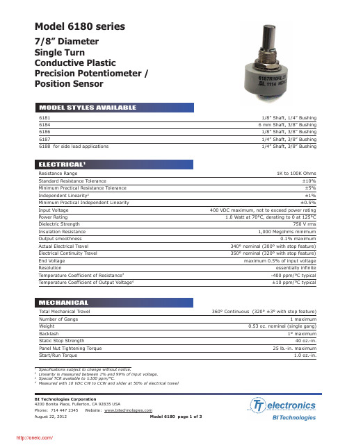
7/8” Diameter Single TurnConductive PlasticPrecision Potentiometer /Position SensorModel 6180 series61811/8” Shaft, 1/4” Bushing 6184 6 mm Shaft, 3/8” Bushing 61861/8” Shaft, 3/8” Bushing 61871/4” Shaft, 3/8” Bushing 6188 for side load applications1/4” Shaft, 3/8” BushingTotal Mechanical Travel 360° Continuous (320° ±3° with stop feature)Number of Gangs 1 maximumWeight 0.53 oz. nominal (single gang)Backlash1° maximumStatic Stop Strength 40 oz.-in.Panel Nut Tightening Torque 25 lb.-in. maximumStart/Run Torque1.0 oz.-in.11Specifications subject to change without notice.2Linearity is measured between 1% and 99% of input voltage.3Special TCR available to ±100 ppm/°C.4Measured with 10 VDC CW to CCW and slider at 50% of electrical travelResistance Range1K to 100K OhmsStandard Resistance Tolerance±10% Minimum Practical Resistance Tolerance ±5%Independent Linearity 2±1%Minimum Practical Independent Linearity ±0.5%Input Voltage 400 VDC maximum, not to exceed power ratingPower Rating 1.0 Watt at 70°C, derating to 0 at 125°CDielectric Strength 750 V rmsInsulation Resistance 1,000 Megohms minimumOutput smoothness 0.1% maximumActual Electrical Travel 340° nominal (300° with stop feature)Electrical Continuity Travel 350° nominal (320° with stop feature)End Voltage maximum 0.5% of input voltageResolutionessentially infinite Temperature Coefficient of Resistance 3-400 ppm/°C typical Temperature Coefficient of Output Voltage 4±10 ppm/°C typicalOperating Temperature Range-40°C to +125°C dynamic, -65°C to +125°C staticTemperature Cycling 5 cycles, -65°C to +125°C, maximum 10% ΔRShock 6 ms Saw-tooth, 100 G’s, 0.1 ms maximum discontinuityVibration10 G’s, 10 to 500 Hz, maximum 2% ΔR, 0.1 ms maximum discontinuityMoisture Resistancefive 24 hour cycles, maximum 25% ΔR High Temperature Exposure 1,000 hours at 125°C, maximum 0.5% ΔV RRotational Life 5 million shaft revolutions Rotational Load Life5 million shaft revolutions, maximum 10% ΔRIngress Protection Rating (IP Code)IP40Model Series Resistance PrefixResistance ValueOptional Feature Code (see table)Optional Non-standard Tolerance6187 R 10K T5 L1.0 xx LFLinearityOptional RoHS Compliant Product CodeSTANDARD RESISTANCE VALUESWhen multiple feature codes are used the P/N shall be in thesame sequence as listed in this table (top to bottom).分销商库存信息:OPTEK-TECHNOLOGY6187R10KL1.0LF6187R5KL1.0LF6187R10KL1.0 6187R5KL1.0。
ATE Corporation AS-05 Antenna Set 30 MHz to 18 GHz

Main Features•30 MHz to 18 GHz frequency range •Excellent Antenna Factor•Tripod adapter for easy vertical-horizontal polarization change •Individual calibration•Robust, rustproof aluminium construction •LightweightAS-05 is a compact size broadband Antenna System composed of a BC-01 Biconical Dipole, LP-04 Log Periodic Dipole Array and DR-01 Double Ridged horn Antenna designed for radiated emissions and immunity testing. It can be used in conjunction with any receiver or spectrum analyzer.Its ideal companion is the EMI Receiver Unit 9060 and 9180 that can be easily mounted on the antenna mast (*).(*)The direct connection between antenna and PMM Receiver Unit eliminates additional sources of uncertainties due to coaxial cable attenuation and scattering. For further information please consult our brochure “Fully CISPR-Compliant Digital EMC/EMI receivers 10 Hz to 18 GHz”.Antenna Set 30 MHz to 18 GHzProvided by: (800)404-ATECAdvanced Test Equipment Rentals®Ordering Information:AS-05 antenna set 30 MHz to 18 GHz with individual calibration reports.AS-05/TC antenna set 30 MHz to 18 GHz with typical calibration reports.Includes: BC-01 biconical antenna; LP-04 Log-periodic antenna; DR-01Double-rideged antenna; TR-01 wooden tripod; RF cable, 6 GHz, N(m)-N(m), 5 m; Soft carrying case; Rigid carrying case (for DR-01), Operating manual; Calibration reports*.* Individual calibration reports are provided with AS-05.AS-05/TC does not include individual calibration but typical antenna factor.Optional accessories:Additional TR-01 Wooden tripod extensible 60 - 180 cm with antenna mounting adapter for fast horizontal to vertical polaritazion changing. Additional RF cable, 3 GHz, N(m)-N(m), 5 m.Sales Office:Via Leonardo da Vinci, 21/2320090 Segrate (Milano) - ITALY Phone: +39 02 2699871Fax: +39 02 26998700Headquarter:Via Benessea, 29/B17035 Cisano sul Neva (SV) - ITALY Phone: +39 0182 58641Fax: +39 0182 586400E-Mail:**************************Internet: www.narda-sts.itRelated ProductsReceiversAntennasCalibrations service• 7010/00: EMI receiver 150 kHz to 1 GHz • 7010/01: EMI receiver 9 kHz to 1 GHz • 7010/03: EMI receiver 9 kHz to 3 GHz • 9010: EMI receiver 10 Hz to 30 MHz • 9010F: EMI receiver 10 Hz to 30 MHz• 9010/03P: EMI receiver 10 Hz to 300 MHz • 9010/30P: EMI receiver 10 Hz to 3 GHz • 9010/60P: EMI receiver 10 Hz to 6 GHz • 9030: EMI Receiver 30 MHz to 3 GHz • 9060: EMI Receiver 30 MHz to 6 GHz •FR-4003: Field Receiver 9 kHz to 30 MHz• LP-02: Log Periodic Antenna 200 MHz to 3 GHz • LP-03: Log Periodic Antenna 800 MHz to 6 GHz • TR-01: Antenna Tripod• VDH-01: Van der Hoofden test-head 20 kHz to 10 MHz • Antenna Set AS-02 (BC01+LP02+TR01)• Antenna Set AS-03 (BC01+LP02+LP03+TR01) • Antenna Set AS-04 (BC01+LP04+TR01)• RA01: Rod Antenna 9 kHz to 30 MHz• RA01-HV: Rod Antenna 150 kHz to 30 MHz •RA01-MIL: Rod Antenna 9 kHz to 30 MHz• Ansi 63,5 Antenna Factor • SAE ARP 958-D• Free-Space Antenna FactorSPECIFICATIONSFrequency range GainAntenna factor Max input power Connector Dimensions (L x H x W)Weight Colour Impedance ConstructionBC-0130 to 200 MHz -15 +2 dBi typical 8 to 14 dB/m typical 100 W N-female 65 x 65 x 137 cm1,8 kg RAL 703550 Ω nominal AluminiumA S 05-F E N -60801 - S p e c i fi c a t i o n s s u b j e c t t o c h a n g e s w i t h o u t p r i o r n o t i c eAS-05Antenna set 30 MHz to 18 GHzLP-04200 MHz to 6 GHz 6 dBi typical 12 to 40 dB/m typical100 W N-female 78 x 10 x 75 cm 1,1 kg RAL 703550 Ω nominal AluminiumDR-016 to 18 GHz 9 to 16 dBi typical 36 to 41 dB/m typical 150 W N-female 55 x 44 x 177 mm 0,25 kg RAL 703550 Ω nominal AluminiumBC-01 - Antenna Factor 106141822A F (d B /m )3090150210MHz MHz MHz MHz LP-04 - Antenna Factor 155253545A F (d B /m )1356GHzGHz GHz GHz DR-01 - Antenna Factor3634384042A F (d B /m )6101418GHzGHz GHz GHz。
UPC4574G2-E1中文资料
UPC4574G2-E1中⽂资料The information in this document is subject to change without notice. Before using this document, please confirm that this is the latest version.Not all products and/or types are available in every country. Please check with an NEC Electronics sales representative for availability and additional information.DATA SHEETDocument No. G15977EJ4V0DS00 (4th edition)Date Published March 2004 N CP(K) Printed in JapanThe mark shows major revised points.1987DESCRIPTIONThe µPC4574 is an ultra low noise, high slew rate quad operational amplifier specifically designed for audio, instrumentation, and communication circuits. The low noise and high frequency capabilities make it ideal for preamps and active filters for instrumentation and professional audio.FEATURESUltra low noise High slew rate Wide bandwidthInternal frequency compensationORDERING INFORMATIONPart NumberPackageµPC4574C µPC4574C(5) 14-pin plastic DIP (7.62 mm (300)) 14-pin plastic DIP (7.62 mm (300)) µPC4574G2 µPC4574G2(5) 14-pin plastic SOP (5.72 mm (225)) 14-pin plastic SOP (5.72 mm (225))EQUIVALENT CIRCUIT (1/4 Circuit)I I I NVVPIN CONFIGURATION (Top View)OUT 4I I4I N4V ?I N3I I3OUT 3OUT 1I I1I N1V +I N2I I2OUT 2PC4574C, 4574C(5), 4574G2, 4574G2(5)µData Sheet G15977EJ4V0DS2ABSOLUTE MAXIMUM RATINGS (T A = 25°C)Parameter SymbolRatings Unit Voltage between V +and V ? Note1V +V0.3 to +36VDifferential Input Voltage V ID ±30 V Input VoltageNote2V IV ??0.3 to V ++0.3 V Output VoltageNote3V OV ??0.3 to V + +0.3VC Package Note4570 mW Power Dissipation G2 PackageNote5P T 550 mW Output Short Circuit DurationNote610 sec Operating Ambient Temperature T A ?20 to +80 °C Storage TemperatureT stg55 to +125°CNotes 1. Reverse connection of supply voltage can cause destruction.2. The input voltage should be allowed to input without damage or destruction. Even during the transition periodof supply voltage, power on/off etc., this specification should be kept. The normal operation will establish when the both inputs are within the Common Mode Input Voltage Range of electrical characteristics.3. This specification is the voltage which should be allowed to supply to the output terminal from externalwithout damage or destructive. Even during the transition period of supply voltage, power on/off etc., this specification should be kept. The output voltage of normal operation will be the Output Voltage Swing of electrical characteristics.4. Thermal derating factor is –7.6 mW/°C when ambient temperature is higher than 50°C.5. Thermal derating factor is –5.5 mW/°C when ambient temperature is higher than 25°C.6. Pay careful attention to the total power dissipation not to exceed the absolute maximum ratings, Note 4 andNote 5.RECOMMENDED OPERATING CONDITIONSParameter Symbol MIN. TYP. MAX. UnitSupply Voltage V ± ±4 ±16 V Output Current I O±10 mASource Resistance R S 50k ?Capacitive Load (A V = +1)C L 100 pFµPC4574C, µPC4574G2±Notes 7. Input bias currents flow out from IC. Because each currents are base current of PNP-transistor on input stage.8.This current flows irrespective of the existence of use.Data Sheet G15977EJ4V0DS 3µPC4574C(5), µPC4574G2(5)±Notes 7. Input bias currents flow out from IC. Because each currents are base current of PNP-transistor on input stage.8.This current flows irrespective of the existence of use.4Data Sheet G15977EJ4V0DSMEASUREMENT CIRCUITFig.1 Total Harmonic Distortion Measurement CircuitnFig.3 Flat Noise Measurement Circuit (FLAT+JIS A)V O = 40 dB x V n100 V n =V O40 dBData Sheet G15977EJ4V0DS 5Data Sheet G15977EJ4V0DS6TYPICAL PERFORMANCE CHARACTERISTICS (T A = 25°C, TYP.) T A - Operating Ambient Temperature - ?CPOWER DISSIPATIONP T - T o t a l P o w e r D i s s i p a t i o n - m W800600400200020*********20406080100120110010 k 1 M 1 k 10100 k 10 Mf - Frequency - HzOPEN LOOP FREQUENCY RESPONSEA V - O p e n L o o p V o l t a g e G a i n - d BV ± = ±15 V202040608021.510.50?0.5?1?1.5?2T A - Operating Ambient Temperature - ?CINPUT OFFSET VOLTAGEV I O - I n p u t O f f s e t V o l t a g e - m V= ±15 VV ±each 5 samples data806040200?20550530510490470450T A - Operating Ambient Temperature - ?CINPUT BIAS CURRENTI B - I n p u t B i a s C u r r e n t - n A= ±15 VV ±f - Frequency - HzLARGE SIGNAL FREQUENCY RESPONSE V o m - O u t p u t V o l t a g e S w i n g - V p -p 01020301001 k 10 k 100 k 1 M 10 MV = ±15 V±R L = 10 k ?I O - Output Current - mAOUTPUT CURRENT LIMITV O - O u t p u t V o l t a g e - V±±5±10±15T A - Operating Ambient Temperature - ?CSUPPLY CURRENTI C C - S u p p l y C u r r e n t - m A12963204020060800V = ±15 V±SUPPLY CURRENTI C C - S u p p l y C u r r e n t - m A12963±10±20V - Supply Voltage - V±Data Sheet G15977EJ4V0DS7COMMON MODE INPUT VOLTAGE RANGE V I C M - C o m m o n M o d e I n p u t V o l t a g e R a n g e - V 20100±10±20V - Supply Voltage - V±VOLTAGE FOLLOWER PULSE RESPONSE V O - O u t p u t V o l t a g e - V10551002468t - Time - sµV = ±15 V ±A V = 1R L = 2 k ?INPUT NOISE VOLTAGE (FLAT + JIS A)V n - I n p u t N o i s e V o l t a g e - V r .m .s .1001010.1101001 k10 k100 kR S - Source Resistance - ?V = ±15 V±µf - Frequency - HzINPUT EQUIVALENT NOISE VOLTAGE DENSITY e n - I n p u t E q u i v a l e n t N o i s e V o l t a g e D e n s i t y - n V / H z20468100 1 k10 k 100 k10±R S = 100 VTOTAL HARMONIC DISTORTIONT H D - T o t a l H a r m o n i c D i s t o r t i o n - %10.0010.010.10.000110100 1 k10 k 100 kf - Frequency - HzV = ±15 V ±V O = 3 V r.m.s.A V = 1R L = 2 k ?Data Sheet G15977EJ4V0DS8PACKAGE DRAWINGS (Unit: mm)14-PIN PLASTIC DIP (7.62 mm (300))ITEM MILLIMETERS A 19.22±0.22.14 MAX.F I J D 1.32±0.12G 3.6±0.3C B 2.54 (T.P.)0.50±0.10R 0~15°H 0.51 MIN.K 7.62 (T.P.)L 6.4±0.23.554.3±0.2N 0.25NOTES1. Each lead centerline is located within 0.25 mm ofits true position (T.P.) at maximum material condition.2. ltem "K" to center of leads when formed parallel.P14C-100-300B1-3M 0.25+0.10?0.05Data Sheet G15977EJ4V0DS9ITEM B C I 14-PIN PLASTIC SOP (5.72 mm (225))D E G H J PMILLIMETERS 1.27 (T.P.)1.42 MAX.A 10.2±0.264.4±0.10.1±0.10.426.5±0.21.49+0.08?0.071.1±0.163°+7°?3°NOTEEach lead centerline is located within 0.1 mm ofits true position (T.P.) at maximum material condition.F 1.59+0.21?0.2K L M N 0.6±0.20.170.10.10+0.08?0.07S14GM-50-225B, C-6RECOMMENDED SOLDERING CONDITIONSThe µPC4574 should be soldered and mounted under the following recommended conditions.For soldering methods and conditions other than those recommended below, contact an NEC Electronics sales representative.For technical information, see the following website.Semiconductor Device Mount Manual (/doc/015a7dda76a20029bd642de6.html/pkg/en/mount/index.html)Type of Surface Mount DeviceµPC4574G2, 4574G2(5): 14-pin plastic SOP (5.72 mm (225))Process ConditionsSymbol Infrared Ray Reflow Peak temperature: 230°C or below (Package surface temperature),Reflow time: 30 seconds or less (at 210°C or higher),Maximum number of reflow processes: 1 time.IR30-00-1Vapor Phase Soldering Peak temperature: 215°C or below (Package surface temperature),Reflow time: 40 seconds or less (at 200°C or higher),Maximum number of reflow processes: 1 time.VP15-00-1Wave Soldering Solder temperature: 260°C or below, Flow time: 10 seconds or less,Maximum number of flow processes: 1 time,Pre-heating temperature: 120°C or below (Package surface temperature).WS60-00-1Partial Heating Method Pin temperature: 300°C or below,Heat time: 3 seconds or less (Per each side of the device).–Caution Apply only one kind of soldering condition to a device, except for "partial heating method", or thedevice will be damaged by heat stress.Type of Through-hole DeviceµPC4574C, 4574C(5): 14-pin plastic DIP (7.62 mm (300))Process ConditionsWave Soldering (only to leads) Solder temperature: 260°C or below, Flow time: 10 seconds or less.Partial Heating Method Pin temperature: 300°C or below,Heat time: 3 seconds or less (per each lead).Caution For through-hole device, the wave soldering process must be applied only to leads, and make sure that the package body does not get jet soldered.Data Sheet G15977EJ4V0DS10The information in this document is current as of March, 2004. The information is subject to change without notice. For actual design-in, refer to the latest publications of NEC Electronics data sheets or data books, etc., for the most up-to-date specifications of N EC Electronics products. N ot all products and/or types are available in every country. Please check with an N EC Electronics sales representative for availability and additional information.No part of this document may be copied or reproduced in any form or by any means without the prior written consent of NEC Electronics. NEC Electronics assumes no responsibility for any errors that may appear in this document.NEC Electronics does not assume any liability for infringement of patents, copyrights or other intellectual property rights of third parties by or arising from the use of NEC Electronics products listed in this document or any other liability arising from the use of such products. No license, express, implied or otherwise, is granted under any patents, copyrights or other intellectual property rights of NEC Electronics or others.Descriptions of circuits, software and other related information in this document are provided for illustrative purposes in semiconductor product operation and application examples. The incorporation of these circuits, software and information in the design of a customer's equipment shall be done under the full responsibility of the customer. NEC Electronics assumes no responsibility for any losses incurred by customers or third parties arising from the use of these circuits, software and information.While NEC Electronics endeavors to enhance the quality, reliability and safety of NEC Electronics products, customers agree and acknowledge that the possibility of defects thereof cannot be eliminated entirely. To minimize risks of damage to property or injury (including death) to persons arising from defects in NEC Electronics products, customers must incorporate sufficient safety measures in their design, such as redundancy, fire-containment and anti-failure features.NEC Electronics products are classified into the following three quality grades: "Standard", "Special" and "Specific".The "Specific" quality grade applies only to NEC Electronics products developed based on a customer-designated "quality assurance program" for a specific application. The recommended applications of an NEC Electronics product depend on its quality grade, as indicated below. Customers must check the quality grade of each NEC Electronics product before using it in a particular application."Standard":Computers, office equipment, communications equipment, test and measurement equipment, audioand visual equipment, home electronic appliances, machine tools, personal electronic equipment and industrial robots. "Special":Transportation equipment (automobiles, trains, ships, etc.), traffic control systems, anti-disastersystems, anti-crime systems, safety equipment and medical equipment (not specifically designed for life support). "Specific":Aircraft, aerospace equipment, submersible repeaters, nuclear reactor control systems, lifesupport systems and medical equipment for life support, etc.The quality grade of NEC Electronics products is "Standard" unless otherwise expressly specified in NEC Electronics data sheets or data books, etc. If customers wish to use NEC Electronics products in applications not intended by NEC Electronics, they must contact an NEC Electronics sales representative in advance to determine NEC Electronics' willingness to support a given application.(Note)(1)"NEC Electronics" as used in this statement means NEC Electronics Corporation and also includes itsmajority-owned subsidiaries.(2)"NEC Electronics products" means any product developed or manufactured by or for NEC Electronics (asdefined above).M8E 02. 11-1。
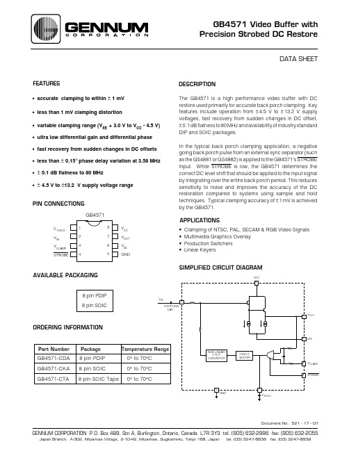
GB4571中文资料
dB
-
µs
±2
mV
3
ms
600
µs
±1
mV
3
µs
VCC-4.5 V
-
V
0.8
V
20
µA
521 - 17 - 00
2
DETAILED DESCRIPTION
The GB4571 is intended for video applications requiring precision DC restoration. The GB4571's signal path consists of a simple Darlington emitter follower for maximum bandwidth performance. With this configuration, the GB4571’s small signal frequency response remains with ± 0.1 dB of 0 dB out to 80 MHz.
The non - linear V to I converter feeds back larger corrective currents to the GB4571's input for larger differences between VCLAMP and VIN than it does for proportionally smaller differences between VCLAMP and VIN voltages. The non-linear V to I converter thus provides for substantially faster recovery from large changes in input signal DC offset while maintaining the overall stability of the device during near-steady-state operation.
1N457A中文资料

1N457/A1N457/A, Rev. A2002 Fairchild Semiconductor CorporationDISCLAIMERFAIRCHILD SEMICONDUCTOR RESERVES THE RIGHT TO MAKE CHANGES WITHOUT FURTHER NOTICE TO ANY PRODUCTS HEREIN TO IMPROVE RELIABILITY , FUNCTION OR DESIGN. FAIRCHILD DOES NOT ASSUME ANY LIABILITY ARISING OUT OF THE APPLICATION OR USE OF ANY PRODUCT OR CIRCUIT DESCRIBED HEREIN; NEITHER DOES IT CONVEY ANY LICENSE UNDER ITS PATENT RIGHTS, NOR THE RIGHTS OF OTHERS.TRADEMARKSThe following are registered and unregistered trademarks Fairchild Semiconductor owns or is authorized to use and is not intended to be an exhaustive list of all such trademarks.LIFE SUPPORT POLICYFAIRCHILD S PRODUCTS ARE NOT AUTHORIZED FOR USE AS CRITICAL COMPONENTS IN LIFE SUPPORTDEVICES OR SYSTEMS WITHOUT THE EXPRESS WRITTEN APPROVAL OF FAIRCHILD SEMICONDUCTOR CORPORATION.As used herein:1. Life support devices or systems are devices orsystems which, (a) are intended for surgical implant intothe body, or (b) support or sustain life, or (c) whosefailure to perform when properly used in accordancewith instructions for use provided in the labeling, can be reasonably expected to result in significant injury to the user.2. A critical component is any component of a life support device or system whose failure to perform can be reasonably expected to cause the failure of the life support device or system, or to affect its safety or effectiveness.PRODUCT STATUS DEFINITIONS Definition of Terms Datasheet Identification Product Status DefinitionAdvance InformationPreliminaryNo Identification Needed Obsolete This datasheet contains the design specifications for product development. Specifications may change in any manner without notice.This datasheet contains preliminary data, andsupplementary data will be published at a later date.Fairchild Semiconductor reserves the right to make changes at any time without notice in order to improve design.This datasheet contains final specifications. Fairchild Semiconductor reserves the right to make changes at any time without notice in order to improve design.This datasheet contains specifications on a product that has been discontinued by Fairchild semiconductor.The datasheet is printed for reference information only.Formative or In Design First ProductionFull ProductionNot In ProductionMICROWIRE OPTOLOGIC OPTOPLANAR PACMAN POPPower247 PowerTrench QFET QSQT Optoelectronics Quiet SeriesFAST FASTr FRFETGlobalOptoisolator GTO HiSeC I 2CISOPLANAR LittleFET MicroFET MicroPakRev. H5âACExBottomless CoolFETCROSSVOLT DenseTrench DOMEEcoSPARK E 2CMOS TM EnSigna TM FACTFACT Quiet SeriesSILENT SWITCHER SMART START SPM STAR*POWER StealthSuperSOT -3SuperSOT -6SuperSOT -8SyncFET TinyLogic TruTranslationâââSTAR*POWER is used under licenseUHC UltraFET VCX â。
PC457L0NIP资料
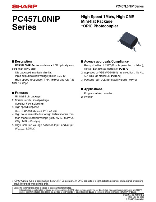
Low level supply current
ICCL
Low level output voltage Current transfer ratio (1)
VOL CTR (1)
*6 Current transfer ratio (2)
CTR (2)
Isolation resistance
RISO
CMH
Conditions IF=16mA VR=5V V=0, f=1MHz IF=0, VCC=5.5V, VO=5.5V
IF=0, VCC=15V, VO=15V
IF=0, VCC=15V, VO=OPEN
IF=16mA, VCC=15V, VO=OPEN IF=16mA, VCC=4.5V, IO=2.4mA
Ptot
100
mW
Operating temperature
Topr −55 to +85 ˚C
Storage temperature
Tstg −55 to +125 ˚C
*4 Isolation voltage
Viso (rms)
3.75
kV
*5 Soldering temperature
Tsol
µs
15
30
− kV/µs
Instantaneous common mode
rejection voltage
CML
(Low level output)
IF=16mA, VCC=5V, VCM=1.0kV(p-p), RL=1.9kΩ
mon mode rejection voltage (CMH : MIN. 15kV/µs, CML : MIN. −15kV/µs) 5. High isolation voltage between input and output (Viso(rms) : 3.75 kV)
2N3506A中文资料

Benefits
Please contact Semicoa for special configurations or (714) 979-1900 Absolute Maximum Ratings Parameter Collector-Emitter Voltage Collector-Base Voltage Emitter-Base Voltage Collector Current, Continuous Power Dissipation, TA = 25OC Derate linearly above 25OC Power Dissipation, TC = 25OC Derate linearly above 25OC Thermal Resistance Operating Junction Temperature Storage Temperature Symbol VCEO VCBO VEBO IC PT PT • Qualification Levels: JAN, JANTX, JANTXV and JANS • Radiation testing available
元器件交易网
2N3506A
Silicon NPN Transistor
Data Sheet
ELECTRICAL CHARACTERISTICS
characteristics specified at TA = 25°C
Off Characteristics Parameter Collector-Base Breakdown Voltage Collector-Emitter Breakdown Voltage Emitter-Base Breakdown Voltage Collector-Emitter Cutoff Current Collector-Emitter Cutoff Current On Characteristics Parameter Symbol hFE1 hFE2 hFE3 hFE4 hFE5 VBEsat1 VBEsat2 VBEsat3 VCEsat1 VCEsat2 VCEsat3 Symbol |hFE| COBO CIBO td tr ts tf Test Conditions IC = 500 mA, VCE = 1 Volts IC = 1.5 A, VCE = 2 Volts IC = 2.5 A, VCE = 3 Volts IC = 3.0 A, VCE = 5 Volts IC = 500 mA, VCE = 2 Volts TA = -55°C IC = 500 mA, IB = 50 mA IC = 1.5 A, IB = 150 mA IC = 2.5 A, IB = 250 mA IC = 500 mA, IB = 50 mA IC = 1.5 A, IB = 150 mA IC = 2.5 A, IB = 250 mA Test Conditions VCE = 5 Volts, IC = 100 mA, f = 20 MHz VCB = 10 Volts, IE = 0 mA, 100 kHZ < f < 1 MHz VEB = 3 Volts, IC = 0 mA, 100 kHZ < f < 1 MHz IC = 1.5 A, IB1 = 150 mA IC = 1.5 A, IB1 = 150 mA IC = 1.5 A, IB1=IB2 = 150 mA IC = 1.5 A, IB1=IB2 = 150 mA Min 50 40 30 25 25 Typ Max 250 200 Units Symbol V(BR)CBO V(BR)CEO V(BR)EBO ICEX1 ICEX2 Test Conditions IC = 100 µA IC = 10 mA IE = 10 µA VCE = 40 Volts, VEB = 4 Volts VCE = 40 Volts, VEB = 4 Volts, TA = 150°C Min 60 40 5 1 1.5 Typ Max Units Volts Volts Volts µA mA
JAN1N5610中文资料

• 1500 Watts for 1 ms Pulse Power Capability • Small Physical Size• Designed for MIL-STD-704A ApplicationsDescriptionZener diodes with a high surge capability qualified to MIL-S-19500/434Absolute Maximum Ratings ( @ 25°C unless noted )1N5610 1N5611 1N5612 1N5613Forward Surge Current, 200 A 200 A 200 A 200 A Zener Surge Current, @ 25C 32.0 A 24.0 A 19.0 A 5.7 A Zener Surge Current @ 150C 5.5 A 4.8 A 3.2 A 1.0 A Storage and Operating Temperature -65C to + 175CZener Voltage See Electrical Characteristics Surge Power See GraphsElectrical Characteristics (T = 25°C unless otherwise noted)Min. Zener Voltage δVz @ 1Ma Max. Zener Voltage λVz @ Is MAX.Reverse LeakageCurrent I R @ V RMAX.Forward V ξ@ 100 ATypical Temp.Coefficient DEVICE TYPEVolts Volts Amps µAVolts Volts % / °C 1N5610*33.047.532.0 5.030.5 4.8.0931N5611*43.763.524.0 5.040.3 4.8.0941N5612*54.078.519.0 5.049.0 4.8.0961N5613*1912655.75.01754.8.100NOTES: * Available as JAN, JANTX and JANTXVδ Duration of applied current ≤300 ms, Duty cycle ≤2%.λ Use a pulse which decays exponentially to 50 % of peak value during 1 ms. (See “ Pulse Waveform “ graph). ξ Peak Sinusoidal surge current of 8.3 ms duration, non repetitivePOWER ZENER RECTIFIERJAN, JANTX, JANTXVApplicationsVoltage transients can be suppressed with series elements, shunt elements or a combination of both. These elements may be passive or active. For low & medium power applications, a series resistor & zener clamp offer several attractive features:1. Simplicity of design.2. High reliability.3. Fast response time.The 1N5610 series will suppress the following transients (defined by MIL-S-704A) without using any series limiting resistance; (except as noted in line #3 below)1. All 600 V transients (category 1 in chart below).2. All 80 V transients except those generated by the main voltage regulator (category 2 in chart below).3. Over-voltage transients from the main voltage regulator (category 3 in chart below) will be suppressed if:a. A 20 ohm series limiting resistor is used, or-b. No series resistance is used & the zener is protected within 500 µs, using (for example) an SCR crowbar.The above statements are based on the source impedances & dv/dt characteristics as given in ARINC* spec# 413; entitled “Guidance for Aircraft Electrical Power Utilization & Transient Protection. This report further defines MIL-STD-704A in regard to large aircraft electrical systems.These surge suppressors are useful in a varierty of other applications where semiconductor devices must function in an environment subject to extremely high, but short term surges.* ARINC stands for Aeronautical Radio Incorporated; Annapolis, Maryland 21401DEVICE OUTLINEDIE OUTLINEFIGURE 1FIGURE 2FIGURE 3。
JAN2N5661资料
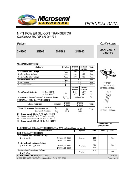
2N5660 2N5661 2N5662 2N5663 200 300 250 400 250 400 6.0 0.5 2.0 2N5660 2N5662 2N5661 2N5663 2.0(1) 1.0(2) (3) 20 15(4) -65 to +200 2N5662 2N5663 6.67 145.8
V(BR)CER V(BR)EBO
Vdc Vdc
6 Lake Street, Lawrence, MA 01841 1-800-446-1158 / (978) 794-1666 / Fax: (978) 689-0803
120101 Page 1 of 2
元器件交易网
SWITCHING CHARACTERISTICS
Turn-On Time VCC = 100 Vdc; IC = 0.5 Adc; IB1 = 15 Adc 2N5660, 2N5662 VCC = 100 Vdc; IC = 0.5 Adc; IB1 = 25 Adc 2N5661, 2N5663 Turn-Off Time VCC = 100 Vdc; IC = 0.5 Adc; IB1 = -IB2 = 15 Adc 2N5660, 2N5662 VCC = 100 Vdc; IC = 0.5 Adc; IB1 = -IB2 = 25 Adc 2N5661, 2N5663
ICBO
ON CHARACTERISTICS (5)
2N5660, 2N5662 2N5661, 2N5663 2N5660, 2N5662 2N5661, 2N5663 All Types All Types
hFE
40 25 40 25 15 5.010 75VCE(sat)
0.4 0.8 1.2 1.5
JAN1N5532-1中文资料
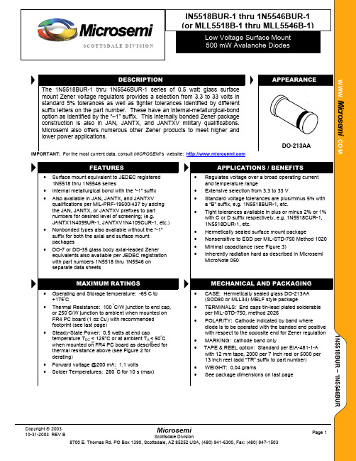
DO-213AA website: APPLICATIONS / BENEFITS1. TOLERANCE AND VOLTAGE DESIGNATION –The JEDEC type numbers without a letter prior to the UR-1 suffix are +/-20% with guaranteed limits for only V Z, I R, and V F.Units with “A” prior to the UR-1 suffix are +/-10% with guaranteed limits for V Z, I R, and V F. Units with guaranteed limits for all six parameters are indicated by a B suffix for +/-5.0% units, C suffix for +/-2.0% and D suffix for +/-1.0% prior to the UR-1 suffix.2. ZENER VOLTAGE (V Z) MEASUREMENT –Nominal zener voltage is measured with the device junction in thermal equilibrium with ambient temperature of 25o C.3. ZENER IMPEDANCE (Z Z) MEASUREMENT –The zener impedance is derived from the 60 Hz ac voltage, which results when an ac current having an rms value equal to 10% of the dc zener current (I ZT) is superimposed on I ZT.4. REVERSE CURRENT (I R) –Reverse currents are guaranteed and are measured at V R as shown on the table.5. MAXIMUM REGULATOR CURRENT (I ZM) –The maximum current shown is as shown in MIL-PRF-19500/437.6. MAXIMUM REGULATION FACTOR (∆V Z) –∆V Z is the maximum difference between V Z at I ZT and V Z at I ZL measured with the device junction in thermal equilibrium.7. PART NUMBER – These may be ordered as either 1N5518BUR-1 thru 1N5546BUR-1 or as MLL5518B-1 thru MLL5546B-1 partnumbers. For military types, use the 1NxxxUR-1 format and also include JAN, JANTX, or JANTXV prefix for desired screening level, e.g. JANTX1N5518BUR-1, JANTXV1N5532BUR-1, JANTXV1N5534CUR-1, JANTXV1N5545DUR-1, etc.Noise density, (N D ) is specified in microvolt-rms per square-root-hertz. Actual measurement is performed using a 1 kHz to 3 kHz frequencybandpass filter at a constant Zener testcurrent (I ZT ) at 25oC ambient temperature.P d R a t e d P o w e r D i s s ip a t i o n(m W )FIGURE 1 Noise DensityMeasurement CircuitT ECT AT EC , End Cap Temperature (oC) or T AAmbient temperature on FR4 PC boardFIGURE 2 Power Derating CurveT y p ic a l C a p a c i t a n c e i n P i c of a r a d s (p f )Zener Voltage V ZFIGURE 4FIGURE 3 Capacitance vs. Zener Voltage (Typical) Zener Diode Characteristics and Symbol IdentificationINCHES MILLIMETERS DIM MIN MAX MIN MAX A 0.063 0.067 1.60 1.70 B 0.130 0.146 3.30 3.70 C0.016 0.022 0.41 0.55 PAD LAYOUT INCHES mmA .200 5.08B .055 1.40C .080 2.03。
inconel各类焊材简介
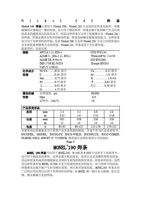
N i c k e l141焊条Nickel 141 焊条主要用于Nickel 200、Nickel 201合金的药皮焊条电弧焊,和镀镍钢材在镀镍层一侧的焊接,也可用于钢的堆焊。
焊缝金属中钛和碳产生反应使游离态的碳降到比较低的水平,因此这种焊条可以用于低碳镍合金(Nickel 201)的焊接。
焊缝金属具有优异的耐蚀性能,特别是耐碱金属腐蚀的能力。
这种焊条也可用于异种材料的焊接,包括Nickel 200合金和Nickel 201合金之间的焊接以及各种铁基和镍基合金的焊接。
Nickel 141 焊条适用于全位置焊接。
能量供给:直流反接规格AWS A 5.11, ENi-1 UNS W82141ASMEⅡ, SFA-5.11, ENi-1 Werkstoff Nr. 2.4156ASME IX, F-No.41 ISO ENi2061DIN 1736 EL-NiTi3 Europe ENiTi3VdTüV 1286.01化学成分Ni+Co……..92.0 最少Cu…………0.25最多范围C…………..0.10 最多Al…………..1.0 最多Mn…………0.75最多Ti………….....1.0-4.0Fe………….0.75最多P…………0.03最多S……….….0.02最多其它………0.50最多Si……….….1.25最多最低机械拉伸强度,psi 60,000性能Mpa 414延伸率,(4d) % 20INCONEL, MONEL, INCOLOY, INCO-WELD, INCOFLUX, INCO-CORED, NI-ROD, NILO, 686CPT和725NDUR 都是超合金国际集团公司的商标。
Page 3MONEL?190焊条MONEL 190焊条可应用于MONEL400,R-405和K-500合金的手工电弧焊中,也可用于钢的表面堆焊。
这种金属可抵抗海水,盐类以及还原酸性物质的侵蚀。
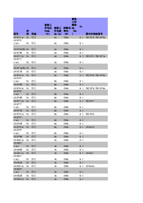
1N系列二极管大全
型号材料用途极限工作电压Vrwm(V)极限工作电流Im(A)耗散功率Pw(W)最高工作频率fm(Hz)Vz国内外相似型号1N4573(A)Si稳压1m400m 6.4THZ4573,THZ4573A 1N4573-1(A1)Si稳压1m400m 6.41N4573AUR1Si稳压1m400m 6.41N4573B Si稳压1m400m 6.41N4574(A)Si稳压1m400m 6.4THZ4574,THZ4574A 1N4574-1(A1)Si稳压1m400m 6.41N4574AUR1Si稳压1m400m 6.41N4574B Si稳压1m400m 6.41N4575(A)Si稳压2m400m 6.4THZ4575,THZ4575A 1N4575-1(A1)Si稳压2m400m 6.41N4575B Si稳压2m400m 6.41N4576(A)Si稳压2m400m 6.4THZ4576,THZ4576A 1N4576-1(A1)Si稳压2m400m 6.41N4576B Si稳压2m400m 6.41N4577(A)Si稳压2m400m 6.4THZ45771N4577-1(A1)Si稳压2m400m 6.41N4577B Si稳压2m400m 6.41N4578(A)Si稳压2m400m 6.4THZ45781N4578-1(A1)Si稳压2m400m 6.41N4578B Si稳压2m400m 6.41N4579(A)Si稳压2m400m 6.41N4611C1N4579-1(A1)Si稳压2m400m 6.41N4579B Si稳压2m400m 6.41N4580(A)Si稳压4m400m 6.41N4580-1(A1)Si稳压4m400m 6.41N4580B Si稳压4m400m 6.41N4581(A)Si稳压4m400m 6.41N46121N4581-1(A1)Si稳压4m400m 6.41N4581B Si稳压4m400m 6.41N4582(A)Si稳压4m400m 6.41N4612A1N4582-1(A1)Si稳压4m400m 6.41N4582B Si稳压4m400m 6.41N4583(A)Si稳压4m400m 6.41N4583-1(A1)Si稳压4m400m 6.41N4583B Si稳压4m400m 6.41N4584(A)Si稳压4m400m 6.41N4612C 1N4584-1(A1)Si稳压4m400m 6.41N4584B Si稳压4m400m 6.41N4611Si稳压2m 6.6NTE5071A 1N4611A Si稳压2m 6.61N4577A 1N4611B Si稳压2m 6.61N4578A 1N4611C Si稳压2m 6.61N4579A 1N4612Si稳压5m 6.6NTE5071A 1N4612A Si稳压5m 6.61N4582A 1N4612B Si稳压5m 6.61N4583A 1N4612C Si稳压5m 6.61N4584A 1N4613Si稳压10m 6.6NTE5071A 1N4613A Si稳压10m 6.61N4582A 1N4613B Si稳压10m 6.61N4584A 1N4613C Si稳压10m 6.61N4614(-1)Si稳压250μ 1.8MZ4614 1N4614C Si稳压250μ 1.81N4614C1Si稳压250μ 1.81N4614CUR1Si稳压250μ 1.81N4614D(D1)Si稳压250μ 1.81N4614DUR1Si稳压250μ 1.81N4615(-1)Si稳压250μ2MZ4615 1N4615C(C1)Si稳压250μ21N4615CUR1Si稳压250μ21N4615D(D1)Si稳压250μ21N4615DUR1Si稳压250μ21N4616(-1)Si稳压250μ 2.2MZ4616 1N4616C(C1)Si稳压250μ 2.21N4616CUR1Si稳压250μ 2.21N4616D(D1)Si稳压250μ 2.21N4616DUR1Si稳压250μ 2.21N4617(-1)Si稳压250μ 2.4MZ4617 1N4617C(C1)Si稳压250μ 2.41N4617CUR1Si稳压250μ 2.41N4617D(D1)Si稳压250μ 2.41N4617DUR1Si稳压250μ 2.41N4618(-1)Si稳压250μ 2.7MZ4618 1N4618C(C1)Si稳压250μ 2.71N4618CUR1Si稳压250μ 2.71N4618D(D1)Si稳压250μ 2.71N4618DUR1Si稳压250μ 2.71N4619(-1)Si稳压250μ3MZ4619 1N4619C(C1)Si稳压250μ31N4619CUR1Si稳压250μ31N4619D(D1)Si稳压250μ31N4619DUR1Si稳压250μ31N4620(-1)Si稳压250μ 3.3MZ4620 1N4620C(C1)Si稳压250μ 3.31N4620CUR1Si稳压250μ 3.31N4620D(D1)Si稳压250μ 3.31N4620DUR1Si稳压250μ 3.31N4621(-1)Si稳压250μ 3.6MZ4621 1N4621C(C1)Si稳压250μ 3.61N4621CUR1Si稳压250μ 3.61N4621D(D1)Si稳压250μ 3.61N4621DUR1Si稳压250μ 3.61N4622(-1)Si稳压250μ 3.9MZ4622 1N4622C(C1)Si稳压250μ 3.91N4622CUR1Si稳压250μ 3.91N4622D(D1)Si稳压250μ 3.91N4622DUR1Si稳压250μ 3.91N4623(-1)Si稳压250μ 4.3MZ4623 1N4623C(C1)Si稳压250μ 4.31N4623CUR1Si稳压250μ 4.31N4623D(D1)Si稳压250μ 4.31N4623DUR1Si稳压250μ 4.31N4624(-1)Si稳压250μ 4.7MZ4624 1N4624C(C1)Si稳压250μ 4.71N4624CUR1Si稳压250μ 4.71N4624D(D1)Si稳压250μ 4.71N4624DUR1Si稳压250μ 4.71N4625(-1)Si稳压250μ 5.1MZ4625 1N4625C(C1)Si稳压250μ 5.11N4625CUR1Si稳压250μ 5.11N4625D(D1)Si稳压250μ 5.11N4625DUR1Si稳压250μ 5.11N4626(-1)Si稳压250μ 5.6MZ4626 1N4626C(C1)Si稳压250μ 5.61N4626CUR1Si稳压250μ 5.61N4626D(D1)Si稳压250μ 5.61N4626DUR1Si稳压250μ 5.61N4627(-1)Si稳压250μ 6.2MZ4627 1N4627C(C1)Si稳压250μ 6.21N4627CUR1Si稳压250μ 6.21N4627D(D1)Si稳压250μ 6.21N4627DUR1Si稳压250μ 6.21N4628Si稳压19m600m 6.8NTE5071A 1N4629Si稳压17m600m7.5NTE138A 1N462C Si稳压0.25m250m 4.71N4630Si稳压15m600m8.2NTE5072A 1N4631Si稳压14m600m9.1NTE139A1N4632Si稳压13m600m10NTE140A 1N4633Si稳压12m600m11NTE5074A 1N4634Si稳压11m600m12NTE142A 1N4635Si稳压9.5m600m13NTE143A 1N4636Si稳压8.5m600m15NTE145A 1N4637Si稳压7.8m600m16NTE5075A 1N4638Si稳压7m600m18CLL5248B 1N4639Si稳压 6.2m600m20CLL5250B 1N4640Si稳压 5.6m600m22CLL5251B 1N4641Si稳压 5.2m600m24CLL5252B 1N4642Si稳压 4.6m600m27CLL5254B 1N4643Si稳压 4.2m600m30CLL5256B 1N4644Si稳压 3.8m600m33CLL5257B 1N4645Si稳压 3.4m600m36CLL5258B 1N4646Si稳压 3.2m600m39CLL5259B 1N4647Si稳压3m600m43CLL5260B 1N4648Si稳压 2.7m600m47CLL5261B 1N4649Si稳压76m1 3.3NTE5066A 1N465Si稳压5m250m 2.61N5223A 1N4650Si稳压69m1 3.6NTE134A 1N4651Si稳压64m1 3.9NTE5067A 1N4652Si稳压58m1 4.3NTE5068A 1N4653Si稳压53m1 4.7LVA1047 1N4654Si稳压49m1 5.1LVA1051 1N4655Si稳压45m1 5.6LVA1056 1N4656Si稳压41m1 6.1LVA1062 1N4657Si稳压37m1 6.8LVA1068 1N4658Si稳压34m17.5LVA1075 1N4659Si稳压31m18.2LVA1082 1N466Si稳压5m250m 3.51N5226A 1N4660Si稳压28m19.1LVA1091 1N4661Si稳压25m110LVA1100 1N4662Si稳压23m111NTE5074A 1N4663Si稳压21m112NTE142A 1N4664Si稳压19m113NTE143A 1N4665Si稳压17m115NTE145A 1N4666Si稳压16m116NTE5075A 1N4667Si稳压14m118NTE5077A 1N4668Si稳压13m120NTE5079A 1N4669Si稳压12m122NTE5080A 1N467Si稳压5m250m 4.11N5230A 1N4670Si稳压11m124NTE5081A 1N4671Si稳压9.5m127NTE146A 1N4672Si稳压8.5m130NTE5084A 1N4673Si稳压7.5m133NTE147A 1N4674Si稳压7m136NTE5085A 1N4675Si稳压 6.5m139NTE5086A1N4676Si稳压6m143NTE5087A 1N4677Si稳压 5.5m147NTE5088A 1N4678Si稳压50μ250m 1.8CMDZ4678 1N4678-1Si稳压50μ250m 1.8MLL4678 1N4678C Si稳压50μ250m 1.81N4678D Si稳压50μ250m 1.81N4679Si稳压50μ250m2LL46791N4679-1Si稳压50μ250m2CMDZ4679 1N4679C Si稳压50μ250m21N4679D Si稳压50μ250m21N468Si稳压5m250m 4.91N5232B 1N4680Si稳压50μ250m 2.2CMZD4680 1N4680-1Si稳压50μ250m 2.2MLL4680 1N4680C Si稳压50μ250m 2.21N4680D Si稳压50μ250m 2.21N4681Si稳压50μ250m 2.4CMDZ4681 1N4681-1Si稳压50μ250m 2.4MLL4681 1N4681C Si稳压50μ250m 2.41N4681D Si稳压50μ250m 2.41N4682Si稳压50μ250m 2.7CMDZ4682 1N4682-1Si稳压50μ250m 2.7MLL4682 1N4682C Si稳压50μ250m 2.71N4682D Si稳压50μ250m 2.71N4683Si稳压50μ250m3CMDZ4683 1N4683-1Si稳压50μ250m3MLL4683 1N4683C Si稳压50μ250m31N4683D Si稳压50μ250m31N4684Si稳压50μ250m 3.3CMDZ4684 1N4684-1Si稳压50μ250m 3.3MLL4684 1N4684C Si稳压50μ250m 3.31N4684D Si稳压50μ250m 3.31N4685Si稳压50μ250m 3.6CMDZ4685 1N4685-1Si稳压50μ250m 3.6MLL4685 1N4685C Si稳压50μ250m 3.61N4685D Si稳压50μ250m 3.61N4686Si稳压50μ250m 3.9CMDZ4686 1N4686-1Si稳压50μ250m 3.9MLL4686 1N4686C Si稳压50μ250m 3.91N4686D Si稳压50μ250m 3.91N4687Si稳压50μ250m 4.3CMDZ4687 1N4687-1Si稳压50μ250m 4.3MLL4687 1N4687C Si稳压50μ250m 4.31N4687D Si稳压50μ250m 4.31N4688Si稳压50μ250m 4.7CMDZ4688 1N4688-1Si稳压50μ250m 4.7MLL4688 1N4688C Si稳压50μ250m 4.71N4688D Si稳压50μ250m 4.71N4689Si稳压50μ250m 5.1CMDZ4689 1N4689-1Si稳压50μ250m 5.1MLL4689 1N4689C Si稳压50μ250m 5.11N4689D Si稳压50μ250m 5.11N469Si稳压5m250m 5.81N5235B 1N4690Si稳压50μ250m 5.6CMDZ4690 1N4690-1Si稳压50μ250m 5.6MLL4690 1N4690C Si稳压50μ250m 5.61N4690D Si稳压50μ250m 5.61N4691Si稳压50μ250m 6.2LL4691 1N4691-1Si稳压50μ250m 6.2MLL4691 1N4691C Si稳压50μ250m 6.21N4691D Si稳压50μ250m 6.21N4692Si稳压50μ250m 6.8LL4692 1N4692-1Si稳压50μ250m 6.81N4692C Si稳压50μ250m 6.81N4692D Si稳压50μ250m 6.81N4693Si稳压50μ250m7.5LL4693 1N4693-1Si稳压50μ250m7.5MLL4693 1N4693C Si稳压50μ250m7.51N4693D Si稳压50μ250m7.51N4694Si稳压50μ250m8.2CMDZ4694 1N4694-1Si稳压50μ250m8.2MLL4694 1N4694C Si稳压50μ250m8.21N4694D Si稳压50μ250m8.21N4695Si稳压50μ250m8.7CMDZ4695 1N4695-1Si稳压50μ250m8.7MLL4695 1N4695C Si稳压50μ250m8.71N4695D Si稳压50μ250m8.71N4696Si稳压50μ250m9.1LL4696 1N4696-1Si稳压50μ250m9.11N4696C Si稳压50μ250m9.11N4696D Si稳压50μ250m9.11N4697Si稳压50μ250m10LL4697 1N4697-1Si稳压50μ250m10MLL4697 1N4697C Si稳压50μ250m101N4697D Si稳压50μ250m101N4698Si稳压50μ250m11CMDZ4698 1N4698-1Si稳压50μ250m11MLL4698 1N4698C Si稳压50μ250m111N4698D Si稳压50μ250m111N4699Si稳压50μ250m12CMDZ4699 1N4699-1Si稳压50μ250m12MLL4699 1N4699C Si稳压50μ250m121N4699D Si稳压50μ250m121N470Si稳压5m250m7.11N4700Si稳压50μ250m13CMDZ47001N4700-1Si稳压50μ250m13MLL4700 1N4700C Si稳压50μ250m131N4700D Si稳压50μ250m131N4701Si稳压50μ250m14CMDZ4701 1N4701-1Si稳压50μ250m14MLL4701 1N4701C Si稳压50μ250m141N4701D Si稳压50μ250m141N4702Si稳压50μ250m15CMDZ4702 1N4702-1Si稳压50μ250m15MLL4702 1N4702C Si稳压50μ250m151N4702D Si稳压50μ250m151N4703Si稳压50μ250m16CMDZ4703 1N4703-1Si稳压50μ250m16MLL4703 1N4703C Si稳压50μ250m161N4703D Si稳压50μ250m161N4704Si稳压50μ250m17CMDZ4704 1N4704-1Si稳压50μ250m17MLL4704 1N4704C Si稳压50μ250m171N4704D Si稳压50μ250m171N4705Si稳压50μ250m18CMDZ4705 1N4705-1Si稳压50μ250m18MLL4705 1N4705C Si稳压50μ250m181N4705D Si稳压50μ250m181N4706Si稳压50μ250m19CMDZ4706 1N4706-1Si稳压50μ250m19MLL4706 1N4706C Si稳压50μ250m191N4706D Si稳压50μ250m191N4707Si稳压50μ250m20CMDZ4707 1N4707-1Si稳压50μ250m20MLL4707 1N4707C Si稳压50μ250m201N4707D Si稳压50μ250m201N4708Si稳压50μ250m22CMDZ4708 1N4708-1Si稳压50μ250m22MLL4708 1N4708C Si稳压50μ250m221N4708D Si稳压50μ250m221N4709Si稳压50μ250m24CMDZ4709 1N4709-1Si稳压50μ250m24MLL4709 1N4709C Si稳压50μ250m241N4709D Si稳压50μ250m241N471Si稳压5m200m 3.51N4710Si稳压50μ250m25CMDZ4710 1N4710-1Si稳压50μ250m25MLL4710 1N4710C Si稳压50μ250m251N4710D Si稳压50μ250m251N4711Si稳压50μ250m27CMDZ4711 1N4711-1Si稳压50μ250m27MLL4711 1N4711C Si稳压50μ250m271N4711D Si稳压50μ250m271N4712Si稳压50μ250m28CMDZ4712 1N4712-1Si稳压50μ250m28MLL4712 1N4712C Si稳压50μ250m281N4712D Si稳压50μ250m281N4713Si稳压50μ250m30CMDZ4713 1N4713-1Si稳压50μ250m30MLL47131N4713C Si稳压50μ250m301N4713D Si稳压50μ250m301N4714Si稳压50μ250m33CMDZ4714 1N4714-1Si稳压50μ250m33MLL4714 1N4714C Si稳压50μ250m331N4714D Si稳压50μ250m331N4715Si稳压50μ250m36LL47151N4715-1Si稳压50μ250m36MLL4715 1N4715C Si稳压50μ250m361N4715D Si稳压50μ250m361N4716Si稳压50μ250m39LL47161N4716-1Si稳压50μ250m39MLL4716 1N4716C Si稳压50μ250m391N4716D Si稳压50μ250m391N4717Si稳压50μ250m43LL47171N4717-1Si稳压50μ250m43MLL4717 1N4717C Si稳压50μ250m431N4717D Si稳压50μ250m431N472Si稳压5m200m 3.51N4728Si稳压76m1 3.3APD3.3A 1N4728A Si稳压76m1 3.3BZX85C3V3 1N4728C Si稳压76m1 3.31N4728D Si稳压76m1 3.31N4729Si稳压69m1 3.6NTE134A 1N4729A Si稳压69m1 3.6BZX85C3V6 1N4729C Si稳压69m1 3.61N4729D Si稳压69m1 3.61N473Si稳压5m200m 3.51N4730Si稳压64m1 3.9NTE5067A 1N4730A Si稳压64m1 3.9BZX85C4V3 1N4730C Si稳压64m1 3.91N4730D Si稳压64m1 3.91N4731Si稳压58m1 4.3NTE5068A 1N4731A Si稳压58m1 4.3BZX8VC4V3 1N4731C Si稳压58m1 4.31N4731D Si稳压58m1 4.31N4732Si稳压53m1 4.7NTE5069A 1N4732A Si稳压53m1 4.7BZX85C4V7 1N4732C Si稳压53m1 4.71N4732D Si稳压53m1 4.71N4733Si稳压49m1 5.1NTE135A 1N4733A Si稳压49m1 5.1BZX85V5V1 1N4733C Si稳压49m1 5.11N4733D Si稳压49m1 5.11N4734Si稳压45m1 5.6NTE136A 1N4734A Si稳压45m1 5.6BZX85C5V6 1N4734C Si稳压45m1 5.61N4734D Si稳压45m1 5.61N4735Si稳压41m1 6.2NTE137A 1N4735A Si稳压41m1 6.2BZX85C6V2 1N4735C Si稳压41m1 6.21N4735D Si稳压41m1 6.21N4736Si稳压37m1 6.8NTE5071A 1N4736A Si稳压37m1 6.8BZX85C6V8 1N4736C Si稳压37m1 6.81N4736D Si稳压37m1 6.81N4737Si稳压34m17.5NTE138A 1N4737A Si稳压34m17.5BZX85V7V5 1N4737C Si稳压34m17.51N4737D Si稳压34m17.51N4738Si稳压31m18.2NTE5072A 1N4738A Si稳压31m18.2BZX85C8V2 1N4738C Si稳压31m18.21N4738D Si稳压31m18.21N4739Si稳压28m19.1NTE139A 1N4739A Si稳压28m19.11N44031N4739C Si稳压28m19.11N4739D Si稳压28m19.11N474Si稳压5m200m 3.51N4740Si稳压25m110NTE140A 1N4740A Si稳压25m110BZX85C10 1N4740C Si稳压25m1101N4740D Si稳压25m1101N4741Si稳压23m111CDLL3021A 1N4741A Si稳压23m111BZX85C11 1N4741C Si稳压23m1111N4405C 1N4741D Si稳压23m1111N4405D 1N4742Si稳压21m112CDLL3022A 1N4742A Si稳压21m112BZX85C12 1N4742C Si稳压21m1121N4164C 1N4742D Si稳压21m1121N4164D 1N4743Si稳压19m113CDLL3023A 1N4743A Si稳压19m113BZX85C13 1N4743C Si稳压19m1131N4407C 1N4743D Si稳压19m1131N4407D 1N4744Si稳压17m115CDLL3024A 1N4744A Si稳压17m115BZX85C151N4744C Si稳压17m1151N4408C 1N4744D Si稳压17m1151N4408D 1N4745Si稳压15m116CDLL3025A 1N4745A Si稳压15m116BZX85C16 1N4745C Si稳压15m1161N4409C 1N4745D Si稳压15m1161N4409D 1N4746Si稳压14m118CDLL3026A 1N4746A Si稳压14m118BZX85C18 1N4746C Si稳压14m1181N4410C 1N4746D Si稳压14m1181N4410D 1N4747Si稳压13m120LL47471N4747A Si稳压13m120BZX85C20 1N4747C Si稳压13m1201N4411C 1N4747D Si稳压13m1201N4411D 1N4748Si稳压12m122LL47481N4748A Si稳压12m122BZX85C22 1N4748C Si稳压12m1221N4413C 1N4748D Si稳压12m1221N4413D 1N4749Si稳压11m124APD24.0A 1N4749A Si稳压11m124BZX85C24 1N4749C Si稳压11m1241N4413C 1N4749D Si稳压11m1241N4413D 1N475Si稳压5m200m 3.51N4750Si稳压9.5m127APD27.0A 1N4750A Si稳压9.5m127APD27.0B 1N4750C Si稳压9.5m1271N4414C 1N4750D Si稳压9.5m1271N4414D 1N4751Si稳压8.5m130NTE5084A 1N4751A Si稳压8.5m130BZX85C30 1N4751C Si稳压8.5m1301N4415C 1N4751D Si稳压8.5m1301N4415D 1N4752Si稳压7.5m133APD33.0A 1N4752A Si稳压7.5m133BZX85C33 1N4752C Si稳压7.5m1331N4416C 1N4752D Si稳压7.5m1331N4416D 1N4753Si稳压7m136APD36.0A 1N4753A Si稳压7m136APD36.0B 1N4753C Si稳压7m1361N4417C 1N4753D Si稳压7m1361N4417D 1N4754Si稳压 6.5m139APD39.0A 1N4754A Si稳压 6.5m139APD39.0B 1N4754C Si稳压 6.5m1391N4418C 1N4754D Si稳压 6.5m1391N4418D 1N4755Si稳压6m143NTE5087A 1N4755A Si稳压6m143BZX85C43 1N4755C Si稳压6m1431N4419C 1N4755D Si稳压6m1431N4419D1N4756Si稳压 5.5m147NTE5088A 1N4756A Si稳压 5.5m147BZX85C47 1N4756C Si稳压 5.5m1471N4420C 1N4756D Si稳压 5.5m1471N4420D 1N4757Si稳压5m151NTE5089A 1N4757A Si稳压5m151BZX85C51 1N4757C Si稳压5m1511N4421C1N4757D Si稳压5m1511N4421D 1N4758Si稳压 4.5m156NTE5090A 1N4758A Si稳压 4.5m156BZX85C56 1N4758C Si稳压 4.5m1561N4480C 1N4758D Si稳压 4.5m1561N4422D 1N4759Si稳压4m162NTE149A 1N4759A Si稳压4m162BZX85C62 1N4759C Si稳压4m1621N4423C 1N4759D Si稳压4m1621N4423D 1N4760Si稳压 3.7m168NTE5092A 1N4760A Si稳压 3.7m168BZX85C68 1N4760C Si稳压 3.7m1681N4424C 1N4760D Si稳压 3.7m1681N4424D 1N4761Si稳压 3.3m175NTE5093A 1N4761A Si稳压 3.3m175BZX85C75 1N4761C Si稳压 3.3m1751N4425C 1N4761D Si稳压 3.3m1751N4183D 1N4762Si稳压3m182NTE150A 1N4762A Si稳压3m182BZX85C82 1N4762C Si稳压3m1821N4426C 1N4762D Si稳压3m1821N4426D 1N4763Si稳压 2.8m191NTE5095A 1N4763A Si稳压 2.8m191BZX85C91 1N4763C Si稳压 2.8m1911N4185C 1N4763D Si稳压 2.8m1911N4185D 1N4764Si稳压 2.5m1100NTE5096A 1N4764A Si稳压 2.5m1100BZX85C100 1N4764C Si稳压 2.5m11001N4486C 1N4764D Si稳压 2.5m11001N4486D 1N4765(A)Si稳压500μ0.259.11N4766(A)Si稳压500μ0.259.1150631N4767(A)Si稳压500μ0.259.11N4768(A)Si稳压500μ0.259.11N4769(A)Si稳压500μ0.259.11N4770(A)Si稳压1m0.259.1SK9V11N4771(A)Si稳压1m0.259.11N4772(A)Si稳压1m0.259.11N4773(A)Si稳压1m0.259.11N4774(A)Si稳压1m0.259.11N4775(A)Si稳压500μ0.258.51N4776(A)Si稳压500μ0.258.51N4777(A)Si稳压500μ0.258.51N4778(A)Si稳压500μ0.258.51N4779(A)Si稳压500μ0.258.51N4780(A)Si稳压1m0.258.51N4781(A)Si稳压1m0.258.51N4782(A)Si稳压1m0.258.51N4783(A)Si稳压1m0.258.51N4784(A)Si稳压1m0.258.51N4831Si稳压28m 1.29.1LMZ91N4831A Si稳压28m 1.29.11N4739 1N4831B Si稳压28m 1.29.11N4739A 1N4832Si稳压25m 1.210LMZ10CA 1N4832A Si稳压25m 1.2101N4740 1N4832B Si稳压25m 1.2101N4740A 1N4833Si稳压23m 1.211LMZ11CA 1N4833A Si稳压23m 1.2111N4741 1N4833B Si稳压23m 1.2111N4741A 1N4834Si稳压21m 1.212LMZ12CA 1N4834A Si稳压21m 1.2121N4742 1N4834B Si稳压21m 1.2121N4742A 1N4835Si稳压19m 1.213LMZ13CA 1N4835A Si稳压19m 1.2131N4743 1N4835B Si稳压19m 1.2131N4743A 1N4836Si稳压17m 1.215LMZ15CA 1N4836A Si稳压17m 1.2151N4744 1N4836B Si稳压17m 1.2151N4744A 1N4837Si稳压16m 1.216LMZ16CA 1N4837A Si稳压16m 1.2161N4745 1N4837B Si稳压16m 1.2161N4745A 1N4838Si稳压14m 1.218LMZ18CA 1N4838A Si稳压14m 1.2181N4746 1N4838B Si稳压14m 1.2181N4746A 1N4839Si稳压13m 1.220LMZ20CA 1N4839A Si稳压13m 1.2201N4747 1N4839B Si稳压13m 1.2201N4747A 1N4840Si稳压11m 1.222LMZ22CA 1N4840A Si稳压11m 1.2221N4748 1N4840B Si稳压11m 1.2221N4748A 1N4841Si稳压11m 1.224LMZ24CA 1N4841A Si稳压11m 1.2241N4749 1N4841B Si稳压11m 1.2241N4749A 1N4842Si稳压9.3m 1.227LMZ27CA 1N4842A Si稳压9.3m 1.2271N4750 1N4842B Si稳压9.3m 1.2271N4750A 1N4843Si稳压8.3m 1.230LMZ30CA 1N4843A Si稳压8.3m 1.2301N47511N4843B Si稳压8.3m 1.2301N4751A 1N4844Si稳压7.5m 1.233LMZ33CA 1N4844A Si稳压7.5m 1.2331N47521N4844B Si稳压7.5m 1.2331N4752A 1N4845Si稳压7m 1.236LMZ36CA 1N4845A Si稳压7m 1.2361N47531N4845B Si稳压7m 1.2361N4753A1N4846Si稳压 6.5m 1.239LMZ39CA 1N4846A Si稳压 6.5m 1.2391N47541N4846B Si稳压 6.5m 1.2391N4754A 1N4847Si稳压 5.8m 1.243LMZ43CA 1N4847A Si稳压 5.8m 1.2431N47551N4847B Si稳压 5.8m 1.2431N4755A 1N4848Si稳压 5.3m 1.247LMZ47CA 1N4848A Si稳压 5.3m 1.2471N47561N4848B Si稳压 5.3m 1.2471N4756A 1N4849Si稳压5m 1.251LMZ51CA 1N4849A Si稳压5m 1.2511N47571N4849B Si稳压5m 1.2511N4757A 1N4850Si稳压 4.5m 1.256LMZ56CA 1N4850A Si稳压 4.5m 1.2561N47581N4850B Si稳压 4.5m 1.2561N4758A 1N4851Si稳压4m 1.262LMZ62CA 1N4851A Si稳压4m 1.2621N47591N4851B Si稳压4m 1.2621N4759A 1N4852Si稳压 3.7m 1.268LMZ68CA 1N4852A Si稳压 3.7m 1.2681N47601N4852B Si稳压 3.7m 1.2681N4760A 1N4853Si稳压 3.3m 1.275LMZ75CA 1N4853A Si稳压 3.3m 1.2751N47611N4853B Si稳压 3.3m 1.2751N4761A 1N4854Si稳压3m 1.282LMZ82CA 1N4854A Si稳压3m 1.2821N47621N4854B Si稳压3m 1.2821N4762A 1N4855Si稳压 2.8m 1.291LMZ91C1N4855A Si稳压 2.8m 1.2911N47631N4855B Si稳压 2.8m 1.2911N4763A 1N4856Si稳压 2.5m 1.2100LMZ100CA 1N4856A Si稳压 2.5m 1.21001N47641N4856B Si稳压 2.5m 1.21001N4764A 1N4857Si稳压 2.3m 1.2110LMZ110CA 1N4857A Si稳压 2.3m 1.21101M110ZS10 1N4857B Si稳压 2.3m 1.21101M110ZS5 1N4858Si稳压 2.1m 1.2120LMZ120CA 1N4858A Si稳压 2.1m 1.21201M120ZS10 1N4858B Si稳压 2.1m 1.21201M120ZS5 1N4859Si稳压 1.9m 1.2130LMZ130CA1N4859A Si稳压 1.9m 1.21301M130ZS10 1N4859B Si稳压 1.9m 1.21301M130ZS5 1N4860Si稳压 1.7m 1.2150LMZ150CA 1N4860A Si稳压 1.7m 1.21501M150ZS10 1N4860B Si稳压 1.7m 1.21501M150ZS5 1N4881Si稳压40m320NTE5135A 1N4882Si稳压20m336NTE5143A 1N4883Si稳压65m312NTE5127A 1N4884Si稳压40m320NTE5135A 1N4889Si稳压20m562C5Z62B1N4890(A)Si稳压7.5m0.4 6.35MZ6401N4891(A)Si稳压7.5m0.4 6.35MZ6401N4892(A)稳压7.5m0.4 6.35MZ6201N4893(A)稳压7.5m0.4 6.35MZ6201N4894(A)稳压7.5m0.4 6.35MZ6101N4895(A)稳压7.5m0.4 6.35MZ6101N4896(A)Si稳压500μ0.412.8NTE142A 1N4897(A)Si稳压500μ0.412.8NTE143A 1N4898(A)Si稳压500μ0.412.8NTE143A 1N4899(A)Si稳压500μ0.412.8NTE143A 1N4900(A)Si稳压1m0.412.8NTE143A 1N4901(A)Si稳压1m0.412.8NTE143A 1N4902(A)Si稳压1m0.412.8NTE143A 1N4903(A)Si稳压1m0.412.8NTE143A 1N4904(A)Si稳压2m0.412.8NTE143A 1N4905(A)Si稳压2m0.412.8NTE143A 1N4906(A)Si稳压2m0.412.8NTE143A 1N4907(A)Si稳压2m0.412.8NTE143A 1N4908(A)Si稳压4m0.412.8NTE143A 1N4909(A)Si稳压4m0.412.8NTE143A 1N4910(A)Si稳压4m0.412.8NTE143A 1N4911(A)Si稳压4m0.412.8NTE143A 1N4912(A)Si稳压7.5m0.412.8NTE143A 1N4913(A)Si稳压7.5m0.412.8NTE143A 1N4914(A)Si稳压7.5m0.412.8NTE143A 1N4915(A)Si稳压7.5m0.412.8NTE143A 1N4916(A)Si稳压500μ0.419.2NTE5078A 1N4917(A)Si稳压500μ0.419.2NTE5078A 1N4918(A)Si稳压500μ0.419.2NTE5078A 1N4919(A)Si稳压1m0.419.2NTE5078A 1N4920(A)Si稳压1m0.419.2NTE5078A 1N4921(A)Si稳压1m0.419.2NTE5078A 1N4922(A)Si稳压2m0.419.2NTE5078A 1N4923(A)Si稳压2m0.419.2NTE5078A 1N4924(A)Si稳压2m0.419.2NTE5078A 1N4925(A)Si稳压4m0.419.2NTE5078A 1N4926(A)Si稳压4m0.419.2NTE5078A1N4927(A)Si稳压4m0.419.2NTE5078A 1N4928(A)Si稳压4m0.419.2NTE5078A 1N4929(A)Si稳压7.5m0.419.2NTE5078A 1N4930(A)Si稳压7.5m0.419.2NTE5078A 1N4931(A)Si稳压7.5m0.419.2NTE5078A 1N4932(A)Si稳压7.5m0.419.2NTE5078A 1N4954Si稳压175m5 6.81N4955Si稳压175m57.51N4956Si稳压150m58.21N4957Si稳压150m59.11N4958Si稳压125m5101N4959Si稳压125m5111N4960Si稳压100m5121N4961Si稳压100m5131N4962Si稳压75m5151N4963Si稳压75m5161N4964Si稳压65m5181N4965Si稳压65m5201N4966Si稳压50m522UZ5722 1N4967Si稳压50m524UZ5724 1N4968Si稳压50m5271N4969Si稳压40m530UZ5730 1N4970Si稳压40m533UZ5733 1N4971Si稳压30m536SX361N4972Si稳压30m539SX391N4973Si稳压30m543SX431N4974Si稳压25m547SX471N4975Si稳压25m551SX511N4976Si稳压20m556SX561N4977Si稳压20m562SX621N4978Si稳压20m568SX681N4979Si稳压20m575SX751N4980Si稳压15m582SX821N4981Si稳压15m591SX911N4982Si稳压12m5100SX1001N4983Si稳压12m5110SX1101N4984Si稳压10m5120SX1201N4985Si稳压10m5130UZ4113 1N4986Si稳压8m5150UZ4115 1N4987Si稳压8m5160UZ4116 1N4988Si稳压5m5180UZ4118 1N4989Si稳压5m52001N4990Si稳压5m52201N4991Si稳压5m52401N4992Si稳压5m52701N4993Si稳压4m53001N4994Si稳压4m53301N4995Si稳压3m53601N4996Si稳压3m53901N5008Si稳压189m 2.5 3.3NTE5111A 1N5008A Si稳压189m 2.5 3.31N4728A 1N5009Si稳压123m 2.5 3.6NTE5112A 1N5009A Si稳压123m 2.5 3.61N4729A 1N5010Si稳压160m 2.5 3.9NTE5113A 1N5010A Si稳压160m 2.5 3.91N4730A 1N5011Si稳压145m 2.5 4.3NTE5114A 1N5011A Si稳压145m 2.5 4.31N4731A 1N5012Si稳压133m 2.5 4.7NTE5115A 1N5012A Si稳压133m 2.5 4.71N4732A 1N5013Si稳压122m 2.5 5.1NTE5116A 1N5013A Si稳压122m 2.5 5.11N4733A 1N5014Si稳压111m 2.5 5.6NTE5117A 1N5014A Si稳压111m 2.5 5.61N4734A 1N5015Si稳压101m 2.5 6.2NTE5119A 1N5015A Si稳压101m 2.5 6.21N4735A 1N5016Si稳压92m 2.5 6.8NTE5120A 1N5016A Si稳压92m 2.5 6.81N4736A 1N5017Si稳压83m 2.57.5NTE5121A 1N5017A Si稳压83m 2.57.51N4737A 1N5018Si稳压76m 2.58.2NTE5122A 1N5018A Si稳压76m 2.58.21N4738A 1N5019Si稳压69m 2.59.1NTE5124A 1N5019A Si稳压69m 2.59.11N4739A 1N5020Si稳压62m 2.510NTE5125A 1N5020A Si稳压62m 2.5101N4740A 1N5021Si稳压57m 2.511NTE5126A 1N5021A Si稳压57m 2.5111N4741A 1N5022Si稳压52m 2.512NTE5127A 1N5022A Si稳压52m 2.5121N4742A 1N5023Si稳压48m 2.513NTE5128A 1N5023A Si稳压48m 2.5131N4743A 1N5024Si稳压45m 2.514NTE5129A 1N5024A Si稳压45m 2.5141M14ZS5 1N5025Si稳压42m 2.515NTE5130A 1N5025A Si稳压42m 2.5151N4744A 1N5026Si稳压39m 2.516NTE5131A 1N5026A Si稳压39m 2.5161N4745A 1N5027Si稳压37m 2.517NTE5132A 1N5027A Si稳压37m 2.5171M17ZS5 1N5028Si稳压35m 2.518NTE5133A 1N5028A Si稳压35m 2.5181N4746A 1N5029Si稳压33m 2.519NTE5134A 1N5029A Si稳压33m 2.5191M19ZS5 1N5030Si稳压31m 2.521NTE5135A1N5030A Si稳压31m 2.5211N4747A 1N5031Si稳压28m 2.522NTE5136A 1N5031A Si稳压28m 2.5221N4748A 1N5032Si稳压26m 2.524NTE5137A 1N5032A Si稳压26m 2.5241N4749A 1N5033Si稳压25m 2.525NTE5138A 1N5033A Si稳压25m 2.5251M25ZS51N5034Si稳压23m 2.527NTE5139A 1N5034A Si稳压23m 2.5271N4750A 1N5035Si稳压21m 2.530NTE5141A 1N5035A Si稳压21m 2.5301N4751A 1N5036Si稳压19m 2.533NTE5142A 1N5036A Si稳压19m 2.5331N4752A 1N5037Si稳压17m 2.536NTE5143A 1N5037A Si稳压17m 2.5361N4753A 1N5038Si稳压16m 2.539NTE5144A 1N5038A Si稳压16m 2.5391N4754A 1N5039Si稳压15m 2.543NTE5145A 1N5039A Si稳压15m 2.5431N4755A 1N5040Si稳压14m 2.545NTE5146A 1N5040A Si稳压14m 2.5451M45ZS5 1N5041Si稳压13m 2.547NTE5146A 1N5041A Si稳压13m 2.5471N4756A 1N5042Si稳压12m 2.550NTE5147A 1N5042A Si稳压12m 2.5501M50ZS5 1N5043Si稳压12m 2.551NTE5147A 1N5043A Si稳压12m 2.5511N4757A 1N5044Si稳压12m 2.552NTE5147A 1N5044A Si稳压12m 2.5521M52ZS5 1N5045Si稳压11m 2.556NTE5148A 1N5045A Si稳压11m 2.5561N4758A 1N5046Si稳压10m 2.562NTE5150A 1N5046A Si稳压10m 2.5621N4759A 1N5047Si稳压9.2m 2.568NTE5151A 1N5047A Si稳压9.2m 2.5681N4760A 1N5048Si稳压8.3m 2.575NTE5152A 1N5048A Si稳压8.3m 2.5751N4761A 1N5049Si稳压7.6m 2.582NTE5153A 1N5049A Si稳压7.6m 2.5821N4762A 1N5050Si稳压 6.9m 2.591NTE5155A 1N5050A Si稳压 6.9m 2.5911N4763A 1N5051Si稳压 6.2m 2.5100NTE5156A 1N5051A Si稳压 6.2m 2.51001N4764A 1N5052Si稳压70015DS1-2-08E 1N5053Si稳压80015DS1-2-08E 1N5054Si稳压100015A14P1N5055Si稳压1001A14A1N5056Si稳压2001NTE5802 1N5057Si稳压300800m A14A1N5058Si稳压400800m NTE5804 1N5059Si稳压2002G1A1N5059GP Si稳压2001BYT51D 1N5060Si稳压4002G1G1N5060GP Si稳压4001BYT51G 1N5061Si稳压6002G1J1N5061GP Si稳压6001BYT51J 1N5062Si稳压8002G1K1N5062GP Si稳压8001S5277L 1N5063Si稳压75m3 6.8C3Z6.8B 1N5064Si稳压75m37.5C3Z7.5B 1N5065Si稳压75m38.2C3Z8.2B 1N5066Si稳压75m39.1C3Z9.1B 1N5067Si稳压75m310C3Z10B 1N5068Si稳压70m311C3Z11B 1N5069Si稳压50m313C3Z13B 1N5070Si稳压50m314C3Z14B 1N5071Si稳压50m315C3Z15B 1N5072Si稳压50m316C3Z16B 1N5073Si稳压40m318C3Z18B 1N5074Si稳压30m322C3Z22B 1N5075Si稳压30m324C3Z24B 1N5076Si稳压25m327C3Z27B 1N5077Si稳压25m330C3Z30B 1N5078Si稳压20m333C3Z33B 1N5079Si稳压20m336C3Z36B 1N5080Si稳压20m339C3Z39B 1N5081Si稳压20m340C3Z39B 1N5082Si稳压15m343C3Z43B 1N5083Si稳压15m345C3Z45B 1N5084Si稳压15m347C3Z47B 1N5085Si稳压15m350C3Z50B 1N5086Si稳压15m351C3Z51B 1N5087Si稳压10m356C3Z56B 1N5088Si稳压10m360C3Z60B 1N5089Si稳压10m362C3Z62B 1N5090Si稳压10m368C3Z68B 1N5091Si稳压10m370C3Z68B 1N5092Si稳压10m375C3Z75B 1N5093Si稳压10m380C3Z80B 1N5094Si稳压10m382C3Z82B 1N5095Si稳压8m391C3Z91B 1N5096Si稳压5m3110C3Z110B 1N5097Si稳压5m3120C3Z120B 1N5098Si稳压5m3130C3Z130B1N5099Si稳压5m3140C3Z140B 1N5100Si稳压4m3160C3Z160B 1N5101Si稳压4m3170C3Z160B 1N5102Si稳压4m3180C3Z180B 1N5103Si稳压4m3190C3Z180B 1N5104Si稳压4m3200C3Z200B 1N5105Si稳压3m32201M110ZSB5 1N5106Si稳压3m32401M120ZSB5 1N5107Si稳压3m32601M130ZSB5 1N5108Si稳压3m32701M135ZSB5 1N5109Si稳压3m32801M140ZSB5 1N5110Si稳压3m33001M150ZSB5 1N5111Si稳压2m33201M160ZSB5 1N5112Si稳压2m33301M165ZSB5 1N5113Si稳压2m33401M170ZSB5 1N5114Si稳压2m33601M180ZSB5 1N5115Si稳压2m33801M190ZSB5 1N5116Si稳压2m33901M195ZSB5 1N5117Si稳压2m34001N5118Si稳压100m514NTE5129A 1N5119Si稳压30m540NTE5144A 1N5120Si稳压30m545NTE5146A 1N5121Si稳压25m550NTE5147A 1N5122Si稳压20m560NTE5149A 1N5123Si稳压20m570NTE5151A 1N5124Si稳压15m580NTE5375B 1N5125Si稳压15m590NTE5155A 1N5126Si稳压8m5140NTE5160A 1N5127Si稳压8m5170NTE5163A 1N5128Si稳压5m5190NTE5165A 1N5129Si稳压5m5260NTE5159A 1N5130Si稳压4m52801N5131Si稳压4m5320NTE5162A 1N5132Si稳压4m5340NTE5163A 1N5133Si稳压4m5380NTE5165A 1N5134Si稳压4m54001N5135Si稳压4m54001N5221Si稳压20m0.5 2.4MLL5221 1N5221A Si稳压20m0.5 2.4MLL5221A 1N5221B Si稳压20m0.5 2.4BZX791N5221C Si稳压20m0.5 2.4MLL5221C 1N5221D Si稳压20m0.5 2.4MLL5221D 1N5222Si稳压20m0.5 2.5NTE5001A 1N5222A Si稳压20m0.5 2.5MLL5222A 1N5222D Si稳压20m0.5 2.51N5223Si稳压20m0.5 2.7NTE5002A 1N5223A Si稳压20m0.5 2.71N5223B Si稳压20m0.5 2.7BZX791N5223C Si稳压20m0.5 2.71N5223D Si稳压20m0.5 2.71N5224Si稳压20m0.5 2.8NTE5003A 1N5224A Si稳压20m0.5 2.81N5224B Si稳压20m0.5 2.8BZX791N5224C Si稳压20m0.5 2.81N5224D Si稳压20m0.5 2.81N5225Si稳压20m0.53NTE5004A 1N5225A Si稳压20m0.531N5225B Si稳压20m0.53BZX791N5225C Si稳压20m0.531N5225D Si稳压20m0.531N5225S Si稳压20m0.331N5225SA Si稳压20m0.331N5225SB Si稳压20m0.331N5226Si稳压20m0.5 3.3NTE5005A 1N5226A Si稳压20m0.5 3.31N5226B Si稳压20m0.5 3.3BZX791N5226C Si稳压20m0.5 3.31N5226D Si稳压20m0.5 3.31N5226S Si稳压20m0.3 3.31N5226SA Si稳压20m0.3 3.31N5226SB Si稳压20m0.3 3.31N5227Si稳压20m0.5 3.6AP3.61N5227A Si稳压20m0.5 3.6CTE3.6 1N5227B Si稳压20m0.5 3.6BZX791N5227C Si稳压20m0.5 3.61N5227D Si稳压20m0.5 3.61N5227S Si稳压20m0.3 3.61N5227SA Si稳压20m0.3 3.61N5227SB Si稳压20m0.3 3.61N5228Si稳压20m0.5 3.9AP3.91N5228A Si稳压20m0.5 3.9CTZ3V9 1N5228B Si稳压20m0.5 3.9BZX791N5228C Si稳压20m0.5 3.91N5228D Si稳压20m0.5 3.91N5228S Si稳压20m0.3 3.91N5228SA Si稳压20m0.3 3.91N5228SB Si稳压20m0.3 3.91N5229Si稳压20m0.5 4.3NTE5008A 1N5229A Si稳压20m0.5 4.3CAZ4.3 1N5229B Si稳压20m0.5 4.3BZX791N5229C Si稳压20m0.5 4.31N5229D Si稳压20m0.5 4.31N5229S Si稳压20m0.3 4.31N5229SA Si稳压20m0.3 4.31N5230Si稳压20m0.5 4.7NTE5009A 1N5230A Si稳压20m0.5 4.7CTZ4V7 1N5230B Si稳压20m0.5 4.7BZX791N5230C Si稳压20m0.5 4.71N5230D Si稳压20m0.5 4.71N5230S Si稳压20m0.3 4.71N5230SA Si稳压20m0.3 4.71N5230SB Si稳压20m0.3 4.71N5231Si稳压20m0.5 5.1NTE5010A 1N5231A Si稳压20m0.5 5.1CTZ5V1 1N5231B Si稳压20m0.5 5.1BZX791N5231C Si稳压20m0.5 5.11N5231D Si稳压20m0.5 5.11N5231S Si稳压20m0.3 5.11N5231SA Si稳压20m0.3 5.11N5231SB Si稳压20m0.3 5.11N5232Si稳压20m0.5 5.6NTE5011A 1N5232A Si稳压20m0.5 5.6CTZ5V6 1N5232B Si稳压20m0.5 5.6BZX791N5232C Si稳压20m0.5 5.61N5232D Si稳压20m0.5 5.61N5232S Si稳压20m0.3 5.61N5232SA Si稳压20m0.3 5.61N5232SB Si稳压20m0.3 5.61N5233Si稳压20m0.56NTE5012A 1N5233A Si稳压20m0.561N5233B 1N5233B Si稳压20m0.56BZX791N5233C Si稳压20m0.561N5233D Si稳压20m0.561N5233S Si稳压20m0.361N5233SA Si稳压20m0.361N5233SB Si稳压20m0.361N5234Si稳压20m0.5 6.2AP6.21N5234A Si稳压20m0.5 6.2CTZ6V2 1N5234B Si稳压20m0.5 6.2BZX791N5234C Si稳压20m0.5 6.21N5234D Si稳压20m0.5 6.21N5234S Si稳压20m0.3 6.21N5234SA Si稳压20m0.3 6.21N5234SB Si稳压20m0.3 6.21N5235Si稳压20m0.5 6.8NTE5014A 1N5235A Si稳压20m0.5 6.81N5235B 1N5235B Si稳压20m0.5 6.8BZX791N5235C Si稳压20m0.5 6.81N5235D Si稳压20m0.5 6.81N5235S Si稳压20m0.3 6.81N5235SB Si稳压20m0.3 6.81N5236Si稳压20m0.57.5NTE5015A 1N5236A Si稳压20m0.57.51N5236B 1N5236B Si稳压20m0.57.5BZX791N5236C Si稳压20m0.57.51N5236D Si稳压20m0.57.51N5236S Si稳压20m0.37.51N5236SA Si稳压20m0.37.51N5236SB Si稳压20m0.37.51N5237Si稳压20m0.58.2NTE5016A 1N5237A Si稳压20m0.58.21N5237B 1N5237B Si稳压20m0.58.2BZX791N5237C Si稳压20m0.58.21N5237D Si稳压20m0.58.21N5237S Si稳压20m0.38.21N5237SA Si稳压20m0.38.21N5237SB Si稳压20m0.38.21N5238Si稳压20m0.58.7NTE5073A 1N5238A Si稳压20m0.58.71N5838B 1N5238B Si稳压20m0.58.7BZX791N5238C Si稳压20m0.58.71N5238D Si稳压20m0.58.71N5238S Si稳压20m0.38.71N5238SA Si稳压20m0.38.71N5238SB Si稳压20m0.38.71N5239Si稳压20m0.59.1NTE5018A 1N5239A Si稳压20m0.59.11N5239B 1N5239B Si稳压20m0.59.1BZX791N5239C Si稳压20m0.59.11N5239D Si稳压20m0.59.11N5239S Si稳压20m0.39.11N5239SA Si稳压20m0.39.11N5239SB Si稳压20m0.39.11N5240Si稳压20m0.510NTE5019A 1N5240A Si稳压20m0.5101N5240B 1N5240B Si稳压20m0.510BZX791N5240C Si稳压20m0.5101N5240D Si稳压20m0.5101N5240S Si稳压20m0.3101N5240SA Si稳压20m0.3101N5240SB Si稳压20m0.3101N5241Si稳压20m0.511NTE5020A 1N5241A Si稳压20m0.5111N5241 1N5241B Si稳压20m0.511BZX791N5241C Si稳压20m0.5111N5241D Si稳压20m0.5111N5241SA Si稳压20m0.3111N5241SB Si稳压20m0.3111N5242Si稳压20m0.512AP121N5242A Si稳压20m0.5121N5242B 1N5242B Si稳压20m0.512BZX791N5242C Si稳压20m0.5121N5242D Si稳压20m0.5121N5242S Si稳压20m0.3121N5242SA Si稳压20m0.3121N5242SB Si稳压20m0.3121N5243Si稳压20m0.513AP131N5243A Si稳压20m0.5131N5243B 1N5243B Si稳压20m0.513BZX791N5243C Si稳压20m0.5131N5243D Si稳压20m0.5131N5243S Si稳压20m0.3131N5243SA Si稳压20m0.3131N5243SB Si稳压20m0.3131N5244Si稳压20m0.514NTE5023A 1N5244A Si稳压20m0.5141N5244B 1N5244B Si稳压20m0.514BZX791N5244C Si稳压20m0.5141N5244D Si稳压20m0.5141N5244S Si稳压20m0.3141N5244SA Si稳压20m0.3141N5244SB Si稳压20m0.3141N5245Si稳压20m0.515AP151N5245A Si稳压20m0.515LL965A 1N5245B Si稳压20m0.515BZX791N5245C Si稳压20m0.5151N5245D Si稳压20m0.5151N5245S Si稳压20m0.3151N5245SA Si稳压20m0.3151N5245SB Si稳压20m0.3151N5246Si稳压20m0.516AP161N5246A Si稳压20m0.5161N5246B 1N5246B Si稳压20m0.516BZX791N5246C Si稳压20m0.5161N5246D Si稳压20m0.5161N5246S Si稳压20m0.3161N5246SA Si稳压20m0.3161N5246SB Si稳压20m0.3161N5247Si稳压20m0.517AP171N5247A Si稳压20m0.517AP17A1N5247B Si稳压20m0.517AP17B1N5247C Si稳压20m0.517。
JAN4N24A中文资料
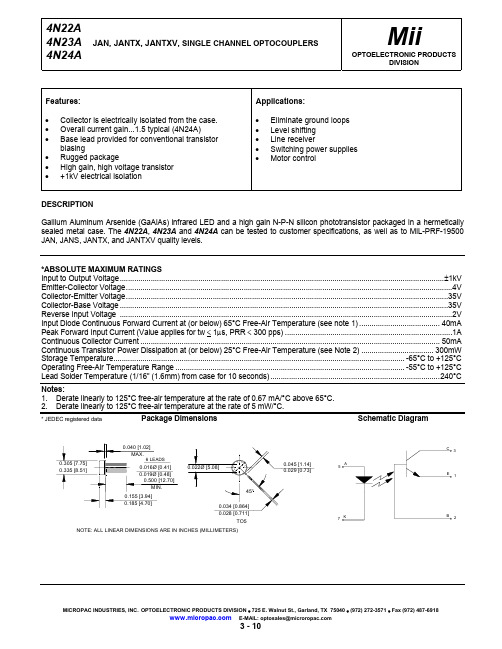
元器件交易网 4N22A, 4N23A, and 4N24A
JAN, JANTX, JANTXV, SINGLE CHANNEL OPTOCOUPLERS
*ELECTRICAL CHARACTERISTICS INPUT LED TA = 25°C Unless otherwise specified
4N22A
1
4N23A
IC(ON)
2.5
4N24A
4
On State Collector Current +100°C
4N22A
1
4N23A
IC(ON)
2.5
4N24A
4
Off State Collector Current Off State Collector Current
+25°C +100°C
V(BR)CBO
35
V(BR)CEO
35
V(BR)EBO
4
MAX
UNITS
V V V
TEST CONDITIONS
IC = 100µA, IB = 0, IF = 0 IC = 1mA, IB = 0, IF = 0 IC = 0, IE = 100µA, IF = 0
NOTE
*COUPLED CHARACTERISTICS TA = 25°C Unless otherwise specified
*ABSOLUTE MAXIMUM RATINGS Input to Output Voltage.............................................................................................................................................................±1kV Emitter-Collector Voltage..............................................................................................................................................................4V Collector-Emitter Voltage............................................................................................................................................................35V Collector-Base Voltage ...............................................................................................................................................................35V Reverse Input Voltage .................................................................................................................................................................2V Input Diode Continuous Forward Current at (or below) 65°C Free-Air Temperature (see note 1) ....................................... 40mA Peak Forward Input Current (Value applies for tw < 1µs, PRR < 300 pps) .................................................................................1A Continuous Collector Current ................................................................................................................................................. 50mA Continuous Transistor Power Dissipation at (or below) 25°C Free-Air Temperature (see Note 2) ................................... 300mW Storage Temperature............................................................................................................................................. -65°C to +125°C Operating Free-Air Temperature Range ............................................................................................................... -55°C to +125°C Lead Solder Temperature (1/16” (1.6mm) from case for 10 seconds) ..................................................................................240°C
欧洲品牌6GN1 1型号气炉焊接缆系列产品说明书
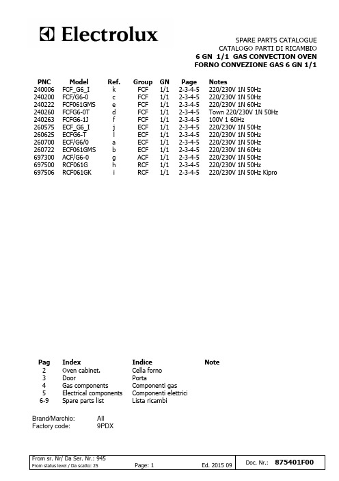
Brand/Marchio: Factory code:
All 9PDX
Note
From sr. Nr/ Da Ser. Nr.: 945
From status level / Da scatto: 25
Page: 1
Ed. 2015 09 Doc. Nr.: 875401F00
From sr. Nr/ Da Ser. Nr.: 945
Page 2-3-4-5 2-3-4-5 2-3-4-5 2-3-4-5 2-3-4-5 2-3-4-5 2-3-4-5 2-3-4-5 2-3-4-5 2-3-4-5 2-3-4-5 2-3-4-5
Notes 220/230V 1N 50Hz 220/230V 1N 50Hz 220/230V 1N 60Hz Town 220/230V 1N 50Hz 100V 1 60Hz 220/230V 1N 50Hz 220/230V 1N 50Hz 220/230V 1N 50Hz 220/230V 1N 60Hz 220/230V 1N 50Hz 220/230V 1N 50Hz 220/230V 1N 50Hz Kipro
Squadretta fissaggio termostato
6 0611804002 002616 Motore per ventola forno
6 0611804601 004083 Motore per ventola forno
7 0850867706 003754 Parete aspirazione
18 0516822400 003685 Controdado per nasello
19 0516827701 003684 Nasello per porta
JANS1N4565AUR-1中文资料
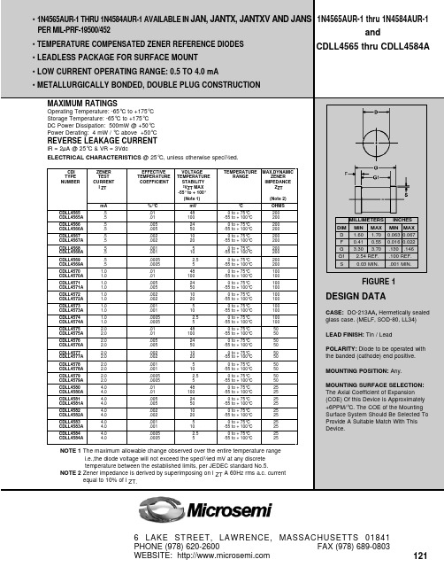
CDLL4565 – CDLL4574
500
CDLL4575 – CDLL4584
ZENER IMPEDANCE ZZT (OHMS)
ZENER IMPEDANCE ZZT (OHMS)
1000 500
100 50
100 50
10
5
10 .25 .5 1.0 1.5 2.0 2.5 3.0 OPERATING CURRENT IZT (mA) 3.5
.8
.9
.25
.5
1.0 1.5 OPERATING CURRENT lZT (mA)
2.0
+.0010 +.0005 0 -.0005 -.0010
CDLL4575 – CDLL4579
CDLL4580 – CDLL4584
0.5
1.0
1.5 2.0 2.5 3.0 3.5 OPERATING CURRENT lZT (mA)
+.0015 +.0010 +.0005 0 CHANGE IN TEMPERATURE COEFFICIENT ( %/°C) -.0005 -.0010 -.0015
CDLL4565 – CDLL4569
CDLL4570 – CDLL4574
.1
.2
.3 .4 .5 .6 .7 OPERATING CURRENT lZT (mA)
1 1.0 2.0 3.0 4.0 5.0 6.0 OPERATING CURRENT IZT (mA)
ZENER IMPEDANCE VS. OPERATING CURRENT
122
1N4565AUR-1 thru 1N4584AUR-1 and CDLL4565 thru CDLL4584A
JANSR2N7391资料
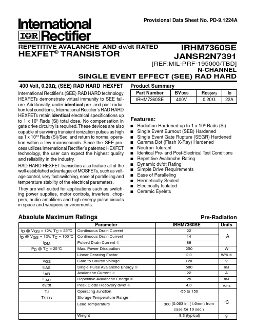
Product SummaryPart Number BV DSS R DS(on)I D IRHM7360SE400V0.20Ω22AFeatures:s Radiation Hardened up to 1 x 10⁵ Rads (Si)s Single Event Burnout (SEB) Hardeneds Single Event Gate Rupture (SEGR) Hardened s Gamma Dot (Flash X-Ray) Hardened s Neutron Tolerants Identical Pre- and Post-Electrical T est Conditions s Repetitive Avalanche Rating s Dynamic dv/dt Ratings Simple Drive Requirements s Ease of Paralleling s Hermetically Sealed s Electrically Isolated sCeramic EyeletsAbsolute Maximum RatingsParameterIRHM7360SEUnits I D @ V GS = 12V , T C = 25°C Continuous Drain Current 22I D @ V GS = 12V , T C = 100°CContinuous Drain Current 14I DMPulsed Drain Current 88P D @ T C = 25°CMax. Power Dissipation 250W Linear Derating Factor 2.0W/K V GS Gate-to-Source Voltage±20V E AS Single Pulse Avalanche Energy 500mJ I AR Avalanche Current22A E AR Repetitive Avalanche Energy 25mJ dv/dt Peak Diode Recovery dv/dt 4.0V/nsT J Operating Junction-55 to 150T STGStorage Temperature Range Lead T emperature 300 (0.063 in. (1.6mm) fromcase for 10 sec.)Weight9.3 (typical)g[REF:MIL-PRF-195000/TBD]N-CHANNELSINGLE EVENT EFFECT (SEE) RAD HARDProvisional Data Sheet No. PD-9.1224APre-Radiation400 Volt, 0.20Ω, (SEE) RAD HARD HEXFETInternational Rectifier’s (SEE) RAD HARD technology HEXFETs demonstrate virtual immunity to SEE fail-ure. Additionally, under identical pre- and post-radia-tion test conditions, International Rectifier’s RAD HARD HEXFETs retain identical electrical specifications up to 1 x 10⁵ Rads (Si) total dose. No compensation in gate drive circuitry is required. T hese devices are also capable of surviving transient ionization pulses as high as 1 x 10¹² Rads (Si)/Sec, and return to normal opera-tion within a few microseconds. Since the SEE pro-cess utilizes International Rectifier’s patented HEXFET technology, the user can expect the highest quality and reliability in the industry.RAD HARD HEXFET transistors also feature all of the well-established advantages of MOSFETs, such as volt-age control, very fast switching, ease of paralleling and temperature stability of the electrical parameters.They are well-suited for applications such as switch-ing power supplies, motor controls, inverters, chop-pers, audio amplifiers and high-energy pulse circuits in space and weapons environments.IRHM7360SE JANSR2N7391REPETITIVE AVALANCHE AND dv/dt RATEDHEXFET ®TRANSISTORo CAThermal ResistanceParameterMin.Typ.Max.UnitsTest ConditionsR thJC Junction-to-Case ——0.50R thJA Junction-to-Ambient ——48K/WRthCSCase-to-Sink—0.21—Typical socket mountSource-Drain Diode Ratings and CharacteristicsParameterMin.Typ.Max.UnitsTest ConditionsI S Continuous Source Current (Body Diode)——22Modified MOSFET symbol showing the I SMPulse Source Current (Body Diode)——88integral reverse p-n junction rectifier.V SD Diode Forward Voltage —— 1.4V T j = 25°C, I S = 22A, V GS = 0V t rr Reverse Recovery Time ——750ns T j = 25°C, I F = 22A, di/dt ≤ 100A/µsQ RR Reverse Recovery Charge ——16µCV DD ≤ 50Vt onForward Turn-On TimeIntrinsic turn-on time is negligible. Turn-on speed is substantially controlled by L S + L D .Electrical Characteristics @ Tj = 25°C (Unless Otherwise Specified)DS = 25Vf = 1.0 MHzIRHM7360SE DevicePre-RadiationATable 2. High Dose Rate1011 Rads (Si)/sec 1012 Rads (Si)/secParameterMin.Typ Max.Min.Typ.Max. Units Test Conditions V DSS Drain-to-Source V oltage——320——320V Applied drain-to-source voltageduring gamma-dotI PP — 6.4—— 6.4—A Peak radiation induced photo-current di/dt ——16—— 2.3A/µsec Rate of rise of photo-current L 120——137——µH Circuit inductance required to limit di/dtTable 3. Single Event EffectsLET (Si)Fluence Range V DS Bias V GS Bias ParameterTyp.UnitsIon(MeV/mg/cm 2)(ions/cm 2)(µm)(V)(V)BV DSS400VNi281 x 105~35320-5Radiation Performance of Rad Hard HEXFETsTable 1. Low Dose RateIRHM7360SEParameter100K Rads (Si)Units Test Conditionsmin.max.BV DSS Drain-to-Source Breakdown Voltage 400—V V GS = 0V , I D = 1.0 mA V GS(th)Gate Threshold Voltage2.5 4.5V GS = V DS , I D = 1.0 mAI GSS Gate-to-Source Leakage Forward —100nA V GS = 20V I GSS Gate-to-Source Leakage Reverse —-100V GS = -20VI DSSZero Gate V oltage Drain Current —50µA V DS = 0.8 x Max Rating, V GS = 0VR DS(on)1Static Drain-to-Source —0.20ΩV GS = 12V , I D =14A On-State Resistance One V SDDiode Forward V oltage—1.35VT C = 25°C, I S = 22A,V GS = 0VInternational Rectifier Radiation Hardened HEX-FETs are tested to verify their hardness capability.The hardness assurance program at International Rectifier uses two radiation environments.Every manufacturing lot is tested in a low dose rate (total dose) environment per MlL-STD-750, test method 1019. International Rectifier has imposed a standard gate voltage of 12 volts per note 6 and a V DSS bias condition equal to 80% of the device rated voltage per note 7. Pre- and post-radiation limits of the devices irradiated to 1 x 10⁵ Rads (Si)are identical and are presented in Table 1. The val-ues in Table 1 will be met for either of the two low dose rate test circuits that are used.Both pre- and post-radiation performance are tested and specified using the same drive circuitry and test conditions in order to provide a direct comparison. It should be noted that at a radiation level of 1 x 10⁵Rads (Si), no change in limits are specified in DC parameters.High dose rate testing may be done on a special request basis, using a dose rate up to 1 x 10¹² Rads (Si)/Sec.International Rectifier radiation hardened HEXFETs have been characterized in neutron and heavy ion Single Event Effects (SEE) environments. Single Event Effects characterization is shown in Table 3.Repetitive Rating; Pulse width limited by maximum junction temperature.Refer to current HEXFET reliability report. @ V DD = 50V, Starting T J = 25°C,E AS = [0.5 * L * (I L 2) * [BV DSS /(BV DSS -V DD )]Peak I L = 22A, V GS = 12V , 25 ≤ R G ≤ 200ΩI SD ≤ 22A, di/dt ≤ 170 A/µs,V DD ≤ BV DSS , T J ≤ 150°C Suggested RG = 2.35ΩPulse width ≤ 300 µs; Duty Cycle ≤ 2%K/W = °C/W W/K = W/°CTotal Dose Irradiation with V GS Bias.12 volt V GS applied and V DS = 0 during irradiation per MIL-STD-750, method 1019.Total Dose Irradiation with V DS Bias.V DS = 0.8 rated BV DSS (pre-radiation)applied and V GS = 0 during irradiation per MlL-STD-750, method 1019.This test is performed using a flash x-raysource operated in the e-beam mode (energy ~2.5 MeV), 30 nsec pulse.Process characterized by independent laboratory.All Pre-Radiation and Post-Radiation test conditions are identical to facilitate direct comparison for circuit applications.WORLD HEADQUARTERS: 233 Kansas St., El Segundo, California 90245, Tel: (310) 322 3331EUROPEAN HEADQUARTERS: Hurst Green, Oxted, Surrey RH8 9BB, UK Tel: ++ 44 1883 732020IR CANADA: 7321 Victoria Park Ave., Suite 201, Markham, Ontario L3R 2Z8, Tel: (905) 475 1897IR GERMANY: Saalburgstrasse 157, 61350 Bad Homburg Tel: ++ 49 6172 96590IR ITALY: Via Liguria 49, 10071 Borgaro, Torino Tel: ++ 39 11 451 0111IR FAR EAST: K&H Bldg., 2F, 3-30-4 Nishi-Ikeburo 3-Chome, Toshima-Ki, Tokyo Japan 171 Tel: 81 3 3983 0086IR SOUTHEAST ASIA: 315 Outram Road, #10-02 Tan Boon Liat Building, Singapore 0316 Tel: 65 221 8371/Data and specifications subject to change without notice.4/96Legend1 - Drain2 - Source3 - Gate Notes:1. Dimensioning and Tolerancing per ANSI Y14.5M-19822. All dimensions are show in millimeters (inches).Conforms to JEDEC Outline TO-254AA Dimensions in Millimeters and (Inches)Legend1 - Drain2 - Source3 - Gate Notes:1. Dimensioning and Tolerancing per ANSI Y14.5M-19822. All dimensions are show in millimeters (inches).3.Leadform is available in either orientation.Dimensions in Millimeters and (Inches)BERYLLIA WARNING PER MIL-PRF-19500Packages containing beryllia shall not be ground, sandblasted,machined, or have other operations performed on them which will produce beryllia or beryllium dust. Furthermore, beryllium oxides packages shall not be placed in acids that will produce fumes containing beryllium.CAUTION。
XN1215资料
60 0.2mA 40 20 0 0 2 4 6 8 10 12 0.1mA
Ta=75˚C
–25˚C
0.3
1
3
10
30
100
1
3
10
30
100
300
பைடு நூலகம்1000
Collector to emitter voltage VCE (V)
Collector current IC (mA)
Collector current IC (mA)
1.5 -0.05 5
0.65±0.15 1
0.95
2.9 -0.05
q
q
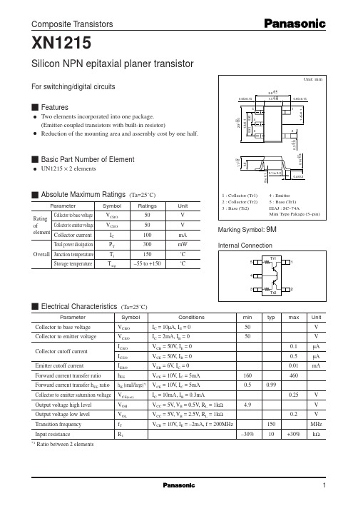
Two elements incorporated into one package. (Emitter-coupled transistors with built-in resistor) Reduction of the mounting area and assembly cost by one half.
Cob — VCB
6
IO — VIN
f=1MHz IE=0 Ta=25˚C 10000 3000 VO=5V Ta=25˚C 100 30
VIN — IO
VO=0.2V Ta=25˚C
Collector output capacitance Cob (pF)
5
Output current IO (µA)
*1
(Ta=25˚C)
Symbol VCBO VCEO ICBO ICEO IEBO hFE hFE (small/large)*1 VCE(sat) VOH VOL fT R1 Conditions IC = 10µA, IE = 0 IC = 2mA, IB = 0 VCB = 50V, IE = 0 VCE = 50V, IB = 0 VEB = 6V, IC = 0 VCE = 10V, IC = 5mA VCE = 10V, IC = 5mA IC = 10mA, IB = 0.3mA VCC = 5V, VB = 0.5V, RL = 1kΩ VCC = 5V, VB = 2.5V, RL = 1kΩ VCB = 10V, IE = –2mA, f = 200MHz –30% 150 10 +30% 4.9 0.2 160 0.5 0.99 0.25 V V V MHz kΩ min 50 50 0.1 0.5 0.01 460 typ max Unit V V µA µA mA
- 1、下载文档前请自行甄别文档内容的完整性,平台不提供额外的编辑、内容补充、找答案等附加服务。
- 2、"仅部分预览"的文档,不可在线预览部分如存在完整性等问题,可反馈申请退款(可完整预览的文档不适用该条件!)。
- 3、如文档侵犯您的权益,请联系客服反馈,我们会尽快为您处理(人工客服工作时间:9:00-18:30)。
4.0
4.5
2.0
2.5
3.0 3.5 4.0 4.5 5.0 OPERATING CURRENT lZT (mA)
5.5
6.0
TYPICAL CHANGE OF TEMPERATURE COEFFICIENT WITH CHANGE IN OPERATING CURRENT
10000 5000 1000
6 LAKE STREET, LAWRENCE, MASSACHUSETTS 01841 PHONE (978) 620-2600 FAX (978) 689-0803 WEBSITE:
121
元器件交易网
CDLL4565 thru CDLL4584A
Operating Temperature: -65°C to +175°C Storage Temperature: -65°C to +175°C DC Power Dissipation: 500mW @ +50°C Power Derating: 4 mW / °C above +50°C lR = 2µA @ 25°C & VR = 3Vdc ELECTRICAL CHARACTERISTICS @ 25°C, unless otherwise speci½ed.
1 1.0 2.0 3.0 4.0 5.0 6.0 OPERATING CURRENT IZT (mA)
ZENER IMPEDANCE VS. OPERATING CURRENT
ቤተ መጻሕፍቲ ባይዱ
122
+.0015 +.0010 +.0005 0 CHANGE IN TEMPERATURE COEFFICIENT ( %/°C) -.0005 -.0010 -.0015
CDLL4565 – CDLL4569
CDLL4570 – CDLL4574
.1
.2
.3 .4 .5 .6 .7 OPERATING CURRENT lZT (mA)
.8
.9
.25
.5
1.0 1.5 OPERATING CURRENT lZT (mA)
2.0
+.0010 +.0005 0 -.0005 -.0010
CDLL4575 – CDLL4579
CDLL4580 – CDLL4584
0.5
1.0
1.5 2.0 2.5 3.0 3.5 OPERATING CURRENT lZT (mA)
CDLL4565 – CDLL4574
500
CDLL4575 – CDLL4584
ZENER IMPEDANCE ZZT (OHMS)
ZENER IMPEDANCE ZZT (OHMS)
1000 500
100 50
100 50
10
5
10 .25 .5 1.0 1.5 2.0 2.5 3.0 OPERATING CURRENT IZT (mA) 3.5
1N4565AUR-1 thru 1N4584AUR-1 and CDLL4565 thru CDLL4584A
REVERSE LEAKAGE CURRENT
mA CDLL4565 CDLL4565A CDLL4566 CDLL4566A CDLL4567 CDLL4567A CDLL4568 CDLL4568A CDLL4569 CDLL4569A CDLL4570 CDLL4570A CDLL4571 CDLL4571A CDLL4572 CDLL4572A CDLL4573 CDLL4573A CDLL4574 CDLL4574A CDLL4575 CDLL4575A CDLL4576 CDLL4576A CDLL4577 CDLL4577A CDLL4578 CDLL4578A CDLL4579 CDLL4579A CDLL4580 CDLL4580A CDLL4581 CDLL4581A CDLL4582 CDLL4582A CDLL4583 CDLL4583A CDLL4584 CDLL4584A .5 .5 .5 .5 .5 .5 .5 .5 .5 .5 1.0 1.0 1.0 1.0 1.0 1.0 1.0 1.0 1.0 1.0 2.0 2.0 2.0 2.0 2.0 2.0 2.0 2.0 2.0 2.0 4.0 4.0 4.0 4.0 4.0 4.0 4.0 4.0 4.0 4.0
元器件交易网
• 1N4565AUR-1 THRU 1N4584AUR-1 AVAILABLE IN JAN, JANTX, JANTXV AND JANS PER MIL-PRF-19500/452 • TEMPERATURE COMPENSATED ZENER REFERENCE DIODES • LEADLESS PACKAGE FOR SURFACE MOUNT • LOW CURRENT OPERATING RANGE: 0.5 TO 4.0 mA • METALLURGICALLY BONDED, DOUBLE PLUG CONSTRUCTION MAXIMUM RATINGS
%/°C .01 .01 .005 .005 .002 .002 .001 .001 .0005 .0005 .01 .01 .005 .005 .002 .002 .001 .001 .0005 .0005 .01 .01 .005 .005 .002 .002 .001 .001 .0005 .0005 .01 .01 .005 .005 .002 .002 .001 .001 .0005 .0005
FIGURE 1
DESIGN DATA
CASE: DO-213AA, Hermetically sealed glass case. (MELF, SOD-80, LL34) LEAD FINISH: Tin / Lead POLARITY: Diode to be operated with the banded (cathode) end positive. MOUNTING POSITION: Any. MOUNTING SURFACE SELECTION: The Axial Coefficient of Expansion (COE) Of this Device is Approximately +6PPM/°C. The COE of the Mounting Surface System Should Be Selected To Provide A Suitable Match With This Device.
NOTE 1 The maximum allowable change observed over the entire temperature range i.e.,the diode voltage will not exceed the speci½ed mV at any discrete temperature between the established limits, per JEDEC standard No.5. NOTE 2 Zener impedance is derived by superimposing on l ZT A 60Hz rms a.c. current equal to 10% of l ZT.
CDI TYPE NUMBER ZENER TEST CURRENT l ZT EFFECTIVE TEMPERATURE COEFFICIENT VOLTAGE TEMPERATURE STABILITY ³VZT MAX -55° to + 100° (Note 1) mV 48 100 24 50 10 20 5 10 2.5 5 48 100 24 50 10 20 5 10 2.5 5 48 100 24 50 10 20 5 10 2.5 5 48 100 24 50 10 20 5 10 2.5 5 TEMPERATURE RANGE MAX.DYNAMIC ZENER IMPEDANCE ZZT (Note 2) °C 0 to + 75°C -55 to + 100°C 0 to + 75°C -55 to + 100°C 0 to + 75°C -55 to + 100°C 0 to + 75°C -55 to + 100°C 0 to + 75°C -55 to + 100°C 0 to + 75°C -55 to + 100°C 0 to + 75°C -55 to + 100°C 0 to + 75°C -55 to + 100°C 0 to + 75°C -55 to + 100°C 0 to + 75°C -55 to + 100°C 0 to + 75°C -55 to + 100°C 0 to + 75°C -55 to + 100°C 0 to + 75°C -55 to + 100°C 0 to + 75°C -55 to + 100°C 0 to + 75°C -55 to + 100°C 0 to + 75°C -55 to + 100°C 0 to + 75°C -55 to + 100°C 0 to + 75°C -55 to + 100°C 0 to + 75°C -55 to + 100°C 0 to + 75°C -55 to + 100°C OHMS 200 200 200 200 200 200 200 200 200 200 100 100 100 100 100 100 100 100 100 100 50 50 50 50 50 50 50 50 50 50 25 25 25 25 25 25 25 25 25 25
