ENG_DS_SR4_DXM_EK1
宏电RTU前置系统安装手册-windows v1.0_hs

ICDPPCNEXUS MPC55xx MPC56xx In-Circuit Debugger
ICDPPCNEXUSMPC55xx / MPC56xx In-Circuit DebuggerQuick Start GuideCopyright 2009, P&E Microcomputer Systems, Inc. All rights reserved.Visit us on the web at Document Version HistoryVersion Date Notes1.0 21 Sep 2009 Initial versionCONTENTS1 Introduction (4)1.1 P&E Compatible Hardware (4)2 Getting Started (5)2.1 Connecting to your Target (5)2.2 Reset Script (6)2.3 Loading Data and Debug Information (7)2.4 CPU and Memory Windows (8)3 Debugging (10)3.1 GOTIL command (10)3.1 Stepping through C instructions (11)3.3 Setting and Reaching Breakpoints (12)3.4 Using Code Window Popup Debug Evaluation Hints (13)3.5 Using the Variables Window (15)3.6 Modifying a Variable (16)3.7 Using the Register Interpreter (17)3.8 Adding Register Field Descriptions to the Variables Window (20)1 IntroductionThis document is a step-by-step guide to using the P&E ICDPPCNEXUS in-circuit debugger software, which is compatible with Freescale MPC55xx / MPC56xx processors. This guide covers the most commonly used features of the debugger: loading binary & debug information, accessing CPU registers & memory, stepping code, setting breakpoints, and monitoring variables.1.1 P&E Compatible HardwareThe following lists the P&E hardware compatible with the ICDPPCNEXUS debugger software.P&E Part Number Interface to host PCCABPPCNEXUS Parallel (LPT) portUSB-ML-PPCNEXUS USB 2.0 (Backwards compatible with USB 1.1 ports) Cyclone MAX Serial (RS232) portUSB 1.1 (Upwards compatible with USB 2.0 ports)Ethernet2 Getting Started2.1 Connecting to your TargetUpon starting the debugger, the connection assistant dialog appears:•Use the “Interface” and “Port” drop-down menus to choose the P&E hardware interface connected between the PC and your target board.•The “Target CPU” setting can safely be left at the “Autodetect” setting for most users. If you experience problems connecting, you can try specifying the exact Freescale device that you are connecting to.• A BDM_SPEED parameter between 2 to 4 can typically be used.Processors running at slower clock speeds will require higher values.Click the Connect button, and ICDPPCNEXUS will attempt to contact the processor. Using the default debugger settings, ICDPPCNEXUS will establish communications and reset the processor.After establishing communications, the main debugger screen will appear, and a debugger reset script macro should automatically execute and complete.2.2 Reset ScriptThis section explains the initialization that the debugger, using a reset script macro file, performs on the processor. The user can view and modify all of the macro file's initialization tasks.The processor Boot Assist Module (BAM) would normally initialize the memory of the processor. However, when running the target application from the debugger, the BAM functionality is disabled. To account for this, the debugger must run a script file on reset. The script initializes the memory of the processor similar to the way in which the BAM would initialize the processor.If ICDPPCNEXUS is launched from the Freescale CodeWarrior IDE, the correct reset script file is automatically selected.If ICDPPCNEXUS is launched stand-alone, the reset script file may need to be configured. Several reset script macros are included with the ICDPPCNEXUS debugger and have a .mac extension. For detailed information, you can view each macro file using a simple text editor such as Notepad. The macro contents will contain useful comments, such as which devices are supported by that particular macro.To configure the debugger reset script macro, select the debugger Configuration menu, Automated Script Options dialog, shown here:2.3 Loading Data and Debug InformationIf ICDPPCNEXUS is launched from the Freescale CodeWarrior IDE, your code will automatically be downloaded to the processor.•RAM projects are loaded into the processor’s internal SRAM.•FLASH projects will invoke the CPROGPPCNEXUS Flash programming software to burn the code into the processor’s internal FLASH.The debug information is also automatically loaded from CodeWarrior, which will allow you to debug using your high level source code and variables.If ICDPPCNEXUS is launched stand-alone, you will need to manually download the code and debug information. Launch the Load Dialog by clicking on the High Level Load button on the debugger tool bar:This dialog allows you to specify the binary/debug file and whether to load into RAM or FLASH. Once you are satisfied with your settings, press the “Process Load Command” button to begin the download process. This step will also load the debug information.2.4 CPU and Memory WindowsThe CPU Window displays all CPU core registers, including the Program Counter (PC) and all general purpose registers.•To modify CPU register contents, double-click the register value. You will be prompted for a new value.The Memory Window displays data at any given memory address. It can be used to view RAM contents, FLASH contents, and values of peripheral registers.•To change the memory address, right-click inside the Memory Window and select “Set Base Address”. You will be prompted for a new address to begin displaying data.•To change the contents in memory, double-click the value in memory that you would like to change. You will be prompted for a new value.3 DebuggingThis section outlines the different debugging capabilities available in the ICDPPCNEXUS debugger once the debug information has been loaded.3.1 GOTIL commandAt this point, your source window will show the assembly language startup code generated by the compiler:If you do not need to debug this section and would like to run the processor until the beginning of your “main” function, you can use the “GOTIL” command.•Type “GOTIL main” in the Status window to tell the debugger to run code until it reaches the “main” function of your code.The “GOTIL” command works with any function in your code.3.1 Stepping through C instructionsStep through the initialization code, or any source code, using the high-level language source step command. Use this feature by typing “HSTEP” in the Status window or by clicking the high-level step button on the debugger tool bar:Each time the HSTEP command executes, the debugger will rapidly single step assembly instructions until it encounters the next source instruction, at which point target execution will cease. When the debugger reaches the next source instruction, all visible windows will be updated with data from the board. After reaching the main function, step through several C language instructions. Notice that some instructions will take longer to step through than others because each C instruction may consist of a greater or fewer number of underlying assembly instructions.3.3 Setting and Reaching BreakpointsIn the source code window, there will be a small red dot and a small blue arrow next to each source instruction that has underlying object code. If a large blue arrow appears on a source line, this indicates that the program counter (PC) currently points to this instruction. If a large red stop sign appears on the source line, this indicates that a breakpoint exists on this line.•Set a breakpoint at an instruction by double-clicking the tiny red dot.•To remove a breakpoint, double-click the large red stop sign.Execution will begin in real-time when you issue the HGO command or click the high-level language GO button on the debugger tool bar:If the debugger encounters a breakpoint, execution will stop on this source line. If it does not encounter a breakpoint, target execution will continue until you press a key or use the stop button on the debugger tool bar:•By double clicking the small blue arrow, you will be issuing a GOTIL command to the address of this source line.A GOTIL command will set a single breakpoint at the desired address, and the processor will begin executing code in real-time from the current program counter (PC). When the debugger encounters the GOTIL address, execution stops. If the debugger does not encounter this location, execution continues until you press akey or use the stop button on the debugger tool bar. Note that all user breakpoints are ignored when the GOTIL command is used.You may also double-click the red and blue symbols in the disassembly window. The disassembly window may display an additional symbol, a small, blue "S" enclosed in a box. This indicates that that a source code instruction begins on this disassembly instruction.3.4 Using Code Window Popup Debug Evaluation HintsWhen debugging source code, it is convenient to view the contents of a variable while viewing your source code. The in-circuit debugger has a feature, debug hints, which displays the value of a variable while the mouse cursor is held over the variable name. The hint may be displayed in any of three locations, as shown below.The three locations for the debug hints are the code window title bar, the status window caption bar, and a popup hint that appears over the variable in source code. You can configure the hints to display in any combination.•Set the locations of debug hints in the configuration menu of the debuggerThe information in the popup hint box is similar to the information displayed in the variables window.The information includes the variable name (i), value ($1), and type (signed long).3.5 Using the Variables WindowThe variables window displays the current value of application variables. The following window shows a display of variables from the example application.Variables that are pointer or reference types are displayed in red. Normal variables are displayed in black.•Add a variable by typing the VAR command, by right clicking the variables window and choosing “Add a variable”, or by hitting the "Add Variable"button in the variables window.When adding a variable using the pop-up menu, the debugger displays the following screen.In the variable field, type the address or name of the variable. Typically, set the type of the variable to “Default”, which means that the variable will be displayed as it is defined in the debugging information. When adding a variable, you may specify the numeric display base of the variable.3.6 Modifying a Variable•To modify the current value of a variable, right-click the variable name in the variables window and select “Modify Variable” to display a dialog.Check the “Modify value” checkbox, and type the variable’s new value. After you click the OK button, the debugger updates the variable value on the target, and the debugger refreshes the variable window to display the new value. Note that the debugger will not edit certain user-defined types, such as enumerated types.•You may also modify a variable’s display properties, such as the type or numeric display base using this dialog.3.7 Using the Register InterpreterThe register interpreter provides a descriptive display of bit fields within the processor’s peripheral registers. The register interpreter allows you easily to change the value of these registers. You may quickly check the current state of a peripheral and examine the configuration of the target device.When you use the register interpreter within the debugger, it reads the current value of the peripheral register, decodes it, and displays it.To launch the register interpreter in the debugger, either use the “R” command or click the view/edit register button on the tool bar:A window will appear that allows you to select a peripheral block to examine.Double clicking the module of choice will launch the register selection window.Double clicking a specific register will launch the edit/display window for that register.The window lists the keystrokes and mouse actions, allowing you to modify the values of each of the fields. After right clicking on a specific field, the register interpreter will display all options for that field.When you quit the register view/edit window by hitting the ESC key, you will be given the opportunity to write the new value into the register, as shown in the following window.3.8 Adding Register Field Descriptions to the Variables WindowAdd register bit fields to the variables window by using the “_TR” command in the debugger or by clicking the "Add Register" button in the variables window. After selecting the register field, the field appears in the debugger variables window, and the debugger will continually update its value.。
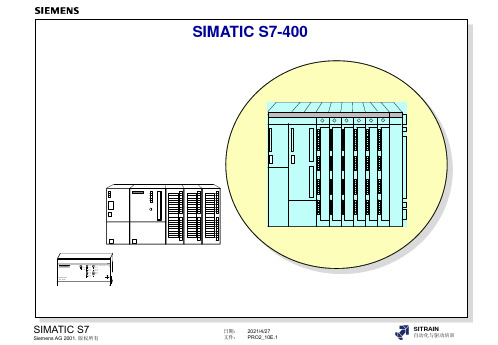
西门子高级编程
P 总线
ER 1/ ER 2
SIMATIC S7
Siemens AG 2001. 版权所有
日期: 2021/4/27 文件: PRO2_10E.5
SITRAIN
自动化与驱动培训
对称多处理器
对称和不对称多处理器
公共 I/O 总线(P 总线)
不对称多处理器
SIMATIC S7
Siemens AG 2001. 版权所有
42/(128)K 128/(384)KB 128/(384)KB
266/533 K 0.8/1.6 MB 0.8/1.6 MB
666 to 2666 K 2 to 8 MB 2 to 8 MB
32(32)/ 32(32 64(64)/64(64) 128(128)/128(
)K
K
128)K
2(2) / 2(2) K 4(4)/4(4)
SIMATIC S7-400
SIEMENS
SIMATIC S7-200
SF RUN STOP
I0.0 I0.1 I0.2 I0.3 I0.4 I0.5 I0.6 I0.7
Q0.0 Mic ro PLC 212 Q0.1 Q0.2 Q0.3 Q0.4 Q0.5
X2 34
SIMATIC S7
Siemens AG 2001. 版权所有
离:600m • 并行 S5 总线连接 • 可能的 S5 扩展单元:
EU 183 U、EU 185 U, ER 701-2、ER 701-3 • 其它 S5 EU • S7-400 CR 上最多 32 个 S5 EU
Send IM
IM314
P C S7 S P CR
U
IM314
S5 EU
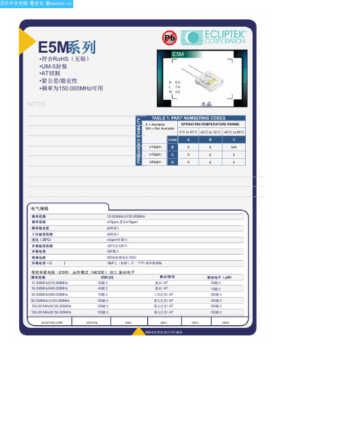
E5M1DBCS-FREQ4-GTR中文资料(ECLIPTEK)中文数据手册「EasyDatasheet - 矽搜」
CR12
.
05/04
规格如有更改,恕不另行通知.
芯片中文手册,看全文,戳
频率公差( 25°C) 2=±10ppm 3= ±15ppm
频率稳定度
B=±10ppm C=±15ppm D=±30ppm
工作温度范围
A = 0°C至50℃ B = -20°C至70℃ C = -40°C至85°C
D
E
4±.1 2±.1
KL
.4±.05 3.9 ±0.1
环境/机械特性
PARAMETER
精细泄漏测试 总泄漏测试 机械冲击 振动 铅完整 可焊性 温度循环 耐焊接热 抗溶剂
SPECIFICATION
MIL-STD-883,方法1014,条件A MIL-STD-883,方法1014,条件C MIL-STD-202,方法213,条件C MIL-STD-883,方法2007条件A MIL-STD-883,2004年法 MIL-STD-883,2002年法 MIL-STD-883,法1010 MIL-STD-202,方法210 MIL-STD-202,方法215
ECLIPTEK CORP.
CRYSTAL
E5M
REEL
R
2.5分钟
M
1.5分钟
S
10分钟
N
O13±.2 40分钟
TU
V 数量/ REEL
30.4马克斯360最大 24.4+2-0 1,000
标记规格
Line 1: E XX.XX Line 2: XX Y ZZ
Frequency in MHz (4 DigitsMaximum + Decimal)
*卷带式仅适用于鸥翼型选项
机械尺寸 ALL DIMENSIONS IN MILLIMETERS
CS5463A
DS-2XS6A46G1 P-IZS C36S80 4 MP ANPR 自动 Number Plat

DS-2XS6A46G1/P-IZS/C36S804 MP ANPR Bullet Solar Power 4G Network Camera KitIt can be used in the areas that are not suitable for laying wired network and electric supply lines, or used for the scenes that feature tough environment and have high demanding for device stability. It can be used for monitoring the farms, electric power cables, water and river system, oil pipelines and key forest areas.It also can be used in the temporary monitoring scenes, such as the large-scale competitions, the sudden public activity, the temporary traffic control and the city construction.Empowered by deep learning algorithms, Hikvision AcuSense technology brings human and vehicle targets classification alarms to front- and back-end devices. The system focuses on human and vehicle targets, vastly improving alarm efficiency and effectiveness.⏹ 80 W photovoltaic panel, 360 Wh chargeable lithium battery⏹ Clear imaging against strong back light due to 120 dB trueWDR technology⏹ Focus on human and vehicle targets classification based ondeep learning⏹Support battery management, battery display, batteryhigh-low temperature protection, charge-dischargeprotection, low-battery sleep protection and remotewakeup ⏹ LTE-TDD/LTE-FDD/WCDMA/GSM 4G wireless networktransmission, support Micro SIM card⏹Water and dust resistant (IP66) *The Wi-Fi module of this product only supports AP mode on Channel 11, and does not support other modes and channels.FunctionRoad Traffic and Vehicle DetectionWith embedded deep learning based license plate capture and recognition algorithms, the camera alone can achieve plate capture and recognition. The algorithm enjoys the high recognition accuracy of common plates and complex-structured plates, which is a great step forward comparing to traditional algorithms. Blocklist and allowlist are available for plate categorization and separate alarm triggering.SpecificationCameraImage Sensor 1/1.8" Progressive Scan CMOSMax. Resolution 2560 × 1440Min. Illumination Color: 0.0005 Lux @ (F1.2, AGC ON), B/W: 0 Lux with light Shutter Time 1 s to 1/100,000 sLensLens Type Auto, Semi-auto, ManualFocal Length & FOV 2.8 to 12 mm, horizontal FOV 107.4° to 39.8°, vertical FOV 56° to 22.4°, diagonal FOV 130.1° to 45.7°8 to 32 mm, horizontal FOV 40.3° to 14.5°, vertical FOV 22.1° to 8.2°, diagonal FOV 46.9° to 16.5°Iris Type Auto-irisLens Mount All In One LensAperture 2.8 to 12 mm: F1.2, 8 to 32 mm: F1.6 DORIDORI 2.8 to 12 mm:Wide: D: 60.0 m, O: 23.8 m, R: 12.0 m, I: 6.0 m Tele: D: 149.0 m, O: 59.1 m, R: 29.8 m, I: 14.9 m 8 to 32 mm:Wide: D: 150.3 m, O: 59.7 m, R: 30.1 m, I: 15.0 m Tele: D: 400 m, O: 158.7 m, R: 80 m, I: 40 mIlluminatorSupplement Light Type IRSupplement Light Range 2.8 to 12 mm: Up to 30 m 8 to 32 mm: Up to 50 mSmart Supplement Light Yes VideoMain Stream Performance mode:50 Hz: 25 fps (2560 × 1440, 1920 × 1080, 1280 × 720) 60 Hz: 30 fps (2560 × 1440, 1920 × 1080, 1280 × 720) Proactive mode:50 Hz: 12.5 fps (2560 × 1440, 1920 × 1080, 1280 × 720) 60 Hz: 15 fps (2560 × 1440, 1920 × 1080, 1280 × 720)Sub-Stream Performance mode:50 Hz: 25 fps (640 × 480, 640 × 360) 60 Hz: 30 fps (640 × 480, 640 × 360) Proactive mode:50 Hz: 12.5 fps (640 × 480, 640 × 360) 60 Hz: 15 fps (640 × 480, 640 × 360)Third Stream 50 Hz: 1 fps (1280 × 720, 640 × 480) 60 Hz: 1 fps (1280 × 720, 640 × 480)Video Compression Main stream: H.264/H.265Sub-stream: H.264/H.265/MJPEGThird Stream: H.265/H.264*Performance mode: main stream supports H.264+, H.265+Video Bit Rate 32 Kbps to 8 MbpsH.264 Type Baseline Profile, Main Profile, High ProfileH.265 Type Main ProfileBit Rate Control CBR/VBRScalable Video Coding (SVC) H.264 and H.265 encodingRegion of Interest (ROI) 4 fixed regions for main streamAudioAudio Compression G.711/G.722.1/G.726/MP2L2/PCM/MP3/AAC-LCAudio Bit Rate 64 Kbps (G.711ulaw/G.711alaw)/16 Kbps (G.722.1)/16 Kbps (G.726)/32 to 192 Kbps (MP2L2)/8 to 320 Kbps (MP3)/16 to 64 Kbps (AAC-LC)Audio Sampling Rate 8 kHz/16 kHz/32 kHz/44.1 kHz/48 kHzEnvironment Noise Filtering YesNetworkSimultaneous Live View Up to 6 channelsAPI Open Network Video Interface (Profile S, Profile G, Profile T), ISAPI, SDK, ISUP, OTAPProtocols TCP/IP, ICMP, HTTP, HTTPS, FTP, DHCP, DNS, DDNS, RTP, RTSP, RTCP, NTP, UPnP, SMTP, SNMP, IGMP, 802.1X, QoS, IPv6, UDP, Bonjour, SSL/TLS, WebSocket, WebSocketsUser/Host Up to 32 users3 user levels: administrator, operator, and userSecurity Password protection, complicated password, HTTPS encryption, 802.1X authentication (EAP-TLS, EAP-LEAP, EAP-MD5), watermark, IP address filter, basic and digest authentication for HTTP/HTTPS, WSSE and digest authentication for Open Network Video Interface, RTP/RTSP over HTTPS, control timeout settings, TLS 1.2, TLS 1.3Network Storage NAS (NFS, SMB/CIFS), auto network replenishment (ANR)Together with high-end Hikvision memory card, memory card encryption and health detection are supported.Client Hik-Connect (proactive mode also supports), Hik-central ProfessionalWeb Browser Plug-in required live view: IE 10+Plug-in free live view: Chrome 57.0+, Firefox 52.0+ Local service: Chrome 57.0+, Firefox 52.0+Mobile CommunicationSIM Card Type MicroSIMFrequency LTE-TDD: Band38/40/41LTE-FDD: Band1/3/5/7/8/20/28 WCDMA: Band1/5/8GSM: 850/900/1800 MHzStandard LTE-TDD/LTE-FDD/WCDMA/GSM ImageWide Dynamic Range (WDR) 120 dBDay/Night Switch Day, Night, Auto, Schedule, Video Trigger Image Enhancement BLC, HLC, 3D DNR, DefogImage Parameters Switch YesImage Settings Saturation, brightness, contrast, sharpness, gain, white balance, adjustable by client software or web browserSNR ≥ 52 dBPrivacy Mask 4 programmable polygon privacy masks InterfaceAudio 1 input (line in), max. input amplitude: 3.3 Vpp, input impedance: 4.7 KΩ, interface type: non-equilibrium,1 output (line out), max. output amplitude: 3.3 Vpp, output impedance: 100 Ω, interface type: non-equilibriumAlarm 1 input, 1 output (max. 12 VDC, 1 A)On-Board Storage Built-in memory card slot, support microSD card, up to 256 GB, Built-in 8 GB eMMC storageReset Key YesEthernet Interface 1 RJ45 10 M/100 M self-adaptive Ethernet portWiegand 1 Wiegand (CardID 26bit, SHA-1 26bit, Hik 34bit, NEWG 72 bit) EventBasic Event Motion detection, video tampering alarm, exception (network disconnected, IP address conflict, illegal login, HDD error)Smart Event Line crossing detection, intrusion detection, region entrance detection, region exiting detection, unattended baggage detection, object removal detection, scene change detection, face detectionLinkage Upload to FTP/NAS/memory card, notify surveillance center, send email, trigger recording, trigger capture, trigger alarm output, audible warningDeep Learning FunctionRoad Traffic and Vehicle Detection Blocklist and allowlist: up to 10,000 records Support license plate recognition License plate recognition rate ≥95%GeneralPower 12 VDC ± 20%, 4-pin M8 waterproof connector1. Standby power consumption: 45 mW2. The average power consumption of 24 hours:3.5 W (4G transmission is excluded).3. The max. power consumption: 7 WMaterial Front cover: metal, body: metal, bracket: metalDimension 816.2 mm × 735.9 mm × 760 mm (32.1" × 28.9" × 29.9") (Max. size of the camera after it is completely assembled)Package Dimension 862 mm × 352 mm × 762 mm (33.9" × 13.9" × 30.0")Weight Approx. 31.885 kg (70.3 lb.)With Package Weight Approx. 25.650 kg (56.5 lb.)Storage Conditions -20 °C to 60 °C (-4 °F to 140 °F). Humidity 95% or less (non-condensing) Startup and OperatingConditions-20 °C to 60 °C (-4 °F to 140 °F). Humidity 95% or less (non-condensing)Language 33 languages: English, Russian, Estonian, Bulgarian, Hungarian, Greek, German, Italian, Czech, Slovak, French, Polish, Dutch, Portuguese, Spanish, Romanian, Danish, Swedish, Norwegian, Finnish, Croatian, Slovenian, Serbian, Turkish, Korean, Traditional Chinese, Thai, Vietnamese, Japanese, Latvian, Lithuanian, Portuguese (Brazil), UkrainianGeneral Function Anti-banding, heartbeat, mirror, flash log, password reset via email, pixel counter BatteryBattery Type LithiumCapacity 360 Wh (90 Wh for each battery)Max. Output Voltage 12.6 V Battery Voltage 10.8 VOperating Temperature Charging: -20 °C to 45 °C (-4 °F to 113 °F) Discharging: -20 °C to 60 °C (-4 °F to 140 °F)Cycle Lifetime Performance mode: 5 days, Proactive mode: 8 days, Standby mode: 80 days *in cloudy/rainy days (25 °C)Battery Life More than 500 cyclesBattery Weight Approx. 2.74 kg (6.0 lb.) (0.685 kg (1.5 lb.) for each battery) ApprovalEMC CE-EMC/UKCA (EN 55032:2015+A11:2020+A1:2020, EN 50130-4:2011+A1:2014); RCM (AS/NZS CISPR 32: 2015);IC (ICES-003: Issue 7)RF CE-RED/UKCA (EN 301908-1, EN 301908-2, EN 301908-13, EN 301511, EN 301489-1, EN 301489-52, EN 62133);ICASA: same as CE-RED;IC ID (RSS-132 Issue 3, RSS-133 Issue 6, RSS-139 Issue 3, RSS-130 Issue 2, RSS-102 Issue 5);MIC (Article 49-6-4 and 49-6-5 the relevant articles and MIC Notice No. 1299 of the Ordinance Regulating Radio Equipment)Safety CB (IEC 62368-1:2014+A11)CE-LVD/UKCA (EN 62368-1:2014/A11:2017) LOA (IEC/EN 60950-1)Environment CE-RoHS (2011/65/EU);WEEE (2012/19/EU);Reach (Regulation (EC) No 1907/2006)Protection Camera: IP66 (IEC 60529-2013)Wind resistance 12 level, up to 40 m/s wind speed resistance⏹Typical ApplicationHikvision products are classified into three levels according to their anti-corrosion performance. Refer to the following description to choose for your using environment.This model has NO SPECIFIC PROTECTION.Level DescriptionTop-level protection Hikvision products at this level are equipped for use in areas where professional anti-corrosion protection is a must. Typical application scenarios include coastlines, docks,chemical plants, and more.Moderate protection Hikvision products at this level are equipped for use in areas with moderate anti-corrosion demands. Typical application scenarios include coastal areas about 2kilometers (1.24 miles) away from coastlines, as well as areas affected by acid rain. No specific protection Hikvision products at this level are equipped for use in areas where no specific anti-corrosion protection is needed.⏹Available ModelDS-2XS6A46G1/P-IZS/C36S80 (2.8-12mm)DS-2XS6A46G1/P-IZS/C36S80 (8-32mm)Dimension。
欧姆龙 协议宏上机手册
串行通信串行通信即通过使用PLC上的串行口(RS-232C口或RS-422/485口)同第三方设备进行通信的过程。
对于PLC上的串行口,它所支持的通信方式有很多种,有连接上位机的上位机通信方式,有连接PLC的1:1PC链接方式,还有连接第三方的通信方式等等。
下面进行一一介绍。
第一节上位机链接通信概要上位机链接系统即Hostlink系统是对于FA系统一种即优化又经济的通信方式,它适合一台上位机与一台或多台PLC进行链接。
上位机可对PLC传送程序,并监控PLC的数据区,以及控制PLC的工作情况。
HOSTLINK系统允许一台上位机通过上位机链接命令向HOSTLINK系统的PLC发送命令,PLC处理来自上位机的每条指令,并把结果传回上位机。
一.HOSTLINK 系统特点通信即可采用RS-232C方式,又可采用RS-422方式,RS-232C方式是基于1:1的通信,距离为15m。
RS-422方式是实现1:N的通信,即一台上位机与多台PLC进行通信,最多可有32台PLC连接到上位机,通信距离最大可达500m。
上位机监控上位机可对PLC的程序进行传送或读取,并可对PLC数据区进行读写操作。
双重检查系统所有通信都将作奇偶检验和帧检验,从而能估计出通信中的错误。
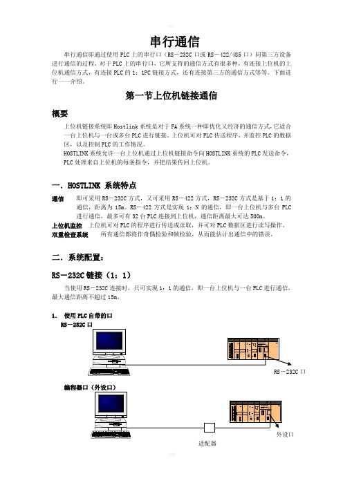
二.系统配置:RS-232C链接(1:1)当使用RS-232C连接时,只可实现1:1的通信,即一台上位机与一台PLC进行通信,最大通信距离不超过15m。
1.使用PLC自带的口RS-232C口编程器口(外设口)注:适配器型号为CPM1-CIF01或CQM1-CIF02,是外设口转RS-232C口的适配器。
2.使用上位链接单元:注:上位链接单元的型号为C200H-LK201,它提供的是一个25芯的RS-232C口。
若连的是CS1系列的PLC,可通过通信模块CS1W-SCU21。
3.使用通信板:RS-422链接(1:N)注:CPM1-CIF11为外设口转RS-422口的适配器。
SINUMERIK 840D sl 软件安装与操作指南说明书
s SINUMERIK 840D sl2016-03-31CNC Software 4.7 SP2 HF4Installation and Operating NotesThe CNC Software 4.7 SP2 HF4 (internal Version 04.07.02.04.005) comprises the following components:Component VersionNCK (incl. NRK) V99.17.07SNCK V02.06.02.00.002SINAMICS V04.70.35.46PLC OpSys (317-3) V32.83.23PLC OpSys (319-3) V32.83.23FB15(sl) 04.07.26CP V02.34.00MCP_CLIENT V01.06.04SINUMERIK Operate V04.07.02.04.002Linux basic system V04.70.80NCK file system driver V04.07.01.01.001NCU-Link Config V03.00.00(SDBs for the configuration of NCU-Link)Profinet FW 14.01.06.04Cycles V04.07.62.03HMIARC Tool 04.05.02.00.003SinIntClient 03.00.04.00.045Requirements:o CNC SW 4.7 SP2 HFx may only be operated on SINUMERIK NCUs 710.3 PN / 710.3B PN, 720.3 PN / 720.3B PN and 730.3 PN / 730.3B PN.o CF card Smart Modular Xceed 8GB. - For the standard version 6FC5851-1XG41-2YA8.o Step 7 version as from V5.5 SP4o Current toolbox from and including V 04.07.23.00o NCU service system from and including V04.70.47o For the use of SINUMERIK Operate internally on NCU, you require the option S00 SINUMERIK Operate on /NCU in combination with real driveso For the use of SINUMERIK Operate externally on PCU or PC, you require the option P87/P88 SINUMERIK Operate on /PCU / PC in combination with real driveso NCU 7x0.3 modules with boot code of PLC version V2.5 (see also the point "Boot code..")**********************************************************************************************************************New options V4.7 SP2 HF1 and higher:6FC5800-0AS14-0YB0 Orientation Offset6FC5800-0AP77-0YB0 CNC user memory expanded6FC5800-0AP80-0YB0 Extended Touch6FC5800-0AP73-0YB0 Run MyRobot /Machining© Siemens AG 2016DF MC R&D 51Page 1 of 12Notes and restrictions:The Software HMI-Pro sl as from including V04.05.03.04 can be used in combination with CNC SW 4.7 SP2 HFx.Additional languages V4.5.2 and V4.7.2.1 are supported. New texts from SW 4.7 SP2 HF1 are possibly displayed in English.The following functions / options have not been released:• F-PLC, that means no 317F or 319F, nor SINUMERIK with dbSI1 either• HTL/TTL encoder in combination with HLA and Safety• The CBA function may only be used together with a declaration regarding the machine-specific approval. • AST from part program (ASTCMD): no support of gantry axes• The Easy-XML functionality included in Operate may not be used by customers for configuring.********************************************************************************************************************** Functional improvements in Operate SW 4.7 SP2 HF4 compared to SW 4.7 SP2 HF3:PR No. 461181 465929 455882 455890 455893Functional improvements in Siemens Cycles SW 4.7 SP2 HF4 compared to SW 4.7 SP2 HF3:PR / RQ 463950 465889 465355Functional improvements in NCK SW 4.7 SP2 HF4 compared to SW 4.7 SP2 HF3:PR No. 454805Functional improvements in Operate SW 4.7 SP2 HF3 compared to SW 4.7 SP2 HF1:PR / RQ 437375 44441 445573 451745Functional improvements in Siemens cycles SW 4.7 SP2 HF3 compared to SW 4.7 SP2 HF1:PR / RQ 435158 441514 441517 436813 451189Functional improvements Linux basic system SW 4.7 SP2 HF3 compared to SW 4.7 SP2 HF1:PR / RQ 408616 427875Functional improvements in NCK SW 4.7 SP2 HF1 compared to SW 4.7 SP1 HF1:PR No. 223981 223983 224078 224176 224329 224590 224719 225480 225635 225760 226113 226134 226226 298293 298481 299426 311840 317281 322349 329598 330513 332500 334927 335256 356081 336706 336721 337226 339418 340140 340469 340814 344404 345306 345306 345762 346665 348212 348713 349183 351642 353091 353472 353606 355123 355443 356904 356907 357128 357174 357822 358272 358656 359001 359007 359927 360178 360543 360550 363495 364464 365308 365574 365731 366094 366094 366166 366484 366717 367592 368094 368634 369953 370430 371206 372680 372954 374197 375457 376765 377148 377151 377151 378642 378767 378869 379143 379474 379474 380340 380731 381765 381791 381959 382053 383143 383202 383208 385000 386211 386315 386315 388342 388342 388836 388926 389770 390300 390330 390364 390847 390847 391660 391807 392293 392304 392400 393820 393820 394144 395547 395852 396459 397177 398392 399256 399309 399812 400045 400273 400639 400854 401008 401503© Siemens AG 2016DF MC R&D 51Page 2 of 12401624 402119 402119 403479 404601 405164 406539 406851 408564 409450 409932 410433 410735 411246 413392 419084 419596 424109 Functional improvements in Operate SW 4.7 SP2 HF1 compared to SW 4.7 SP1 HF1:PR No. 223769 223877 224056 224314 224321 224420 224481 225104 225904 225990 226232 226394 300402 318491 322713 324767 325498 334331 334930 335016 336851 337082 339022 339874 340344 340651 350129 350201 352254 352355 352904 353281 353659 353721 356266 356357 358778 359281 360403 360583 361217 361546 362217 363278 364038 364238 364492 364495 365162 365844 366901 367682 367682 368327 368374 368377 368806 369484 370560 371357 371446 372141 372477 372803 372809 372813 372835 373319 373487 373742 375180 375385 375424 375787 375794 376538 376966 377115 377593 377808 378142 378372 378694 379569 379915 379915 380434 380460 380670 381296 381305 381359 381527 381736 381736 381964 382114 382792 382792 382808 383158 383309 383345 383345 383795 383801 384398 384407 384407 385018 385018 385251 386383 386625 386747 386747 386773 387108 387108 387108 387251 387318 387371 387381 388054 388181 388186 388486 388823 388823 388827 389701 390346 390643 390643 390815 390846 390859 391306 391741 391741 392208 392211 392211 392233 392583 392752 392752 392752 392757 392899 393278 393278 393326 393509 394148 394573 394852 395130 395738 395765 395906 396445 397037 397143 397145 397394 397810 398509 398771 398926 400490 401097 401671 401728 402009 402009 402313 404475 405164 405389 405534 405809 405819 405876 406189 406215 406238 407561 408062 408733 409450 409693 410119 410502 410914 410914 411432 411589 411594 411853 411922 412540 413754 414566 414906 414983 415201 415564 416534 416554 416878 417248 417387 418708 418739 418887 419987 420012 420250 420484 420585 421635 421967 422428 424217 424217 424279 425359 425595 425788 425788 426349 426349 429419 430121 431275 433293 435149 435186 435206 435295 Functional improvements in the Siemens cycles SW 4.7 SP2 HF1 compared to SW 4.7 SP1 HF1:PR No. 223970 224912 225633 226202 287498 307345 310522 311986 327348 333374 339325 345012 345810 347320 348287 350523 359436 359618 360164 364202 364204 371395 371797 375783 376496 376853 377231 377615 377647 378440 379727 379881 380089 380126 380767 380978 381187 381218 381340 381903 383997 385847 385863 386148 388506 389579 389655 390706 392172 392172 392399 392399 392418 392418 392759 392876 392876 392876 393069 393196 393222 393222 394495 394573 396311 396402 397048 398912 399203 399281 399873 399903 400110 400110 400335 400382 401081 401723 401973 402889 402889 405380 408989 409008 409932 409932 409932 410650 411532 412362 413543 414764 416760 420751 424630 426834 428054 431605 Installing the CNC software:The NCU service system >= V04.70.47 is required on a USB stick to install the CNC software.New installations can be performed via the NCU service system and TCU or with WinSCP / AMM /P2P fromV4.6 SP1 HFx.An upgrade or new installation can also be carried out using the tools of the Create MyConfig Version from 4.6 HF1. To do this, a CMC package must be generated that is stored and booted either on a PG, PC, a PCU or a © Siemens AG 2016DF MC R&D 51Page 3 of 12USB stick at the NCU or PCU. The instructions can be found in the Create MyConfig manual.The software may only be installed on a SINUMERIK 8GB CF card – see prerequisites.Boot code of the PLC:Software release 4.7 only starts with PLC boot code V2.5 (or later) internally coded on the NCU hardware.If this PLC boot code has still not been installed, the control will not start (in the 7-segment display"PLC" and SF and DP LED flash red).In this state, the bootcode upgrade can be initiated by actuating the PLC rotary switch. The bootcode is flashed by turning the PLC rotary switch into position 5. This can be identified by the factthat a rotating wheel is displayed in the 7-segment display. This takes approx. 15 seconds. With this procedure, under no circumstances is it permissible that the NCU is switched off! The 7-segment display goes dark after the boot code upgrade has been completed. The PLC rotary switch can now be turned back to position 3 (memory reset) and the system continues to boot.Installing the NCU service system on USB stick:The NCU service system is stored as a USB stick image in directory emergency_bootsys_ncu on the supplied DVD. The copy program installdisk.exe is also included. Connect a USB stick >= 2 GB to your PG resp. PC and determine the relevant drive letters. Call installdisk to copy the NCU service system to the USB stick: installdisk --verbose --blocksize 1m <Image file> <Drive letter:>It is best if the command specified above is executed in a DOS shell.For this, you require administrator rights on your PG / PC.Installation on the NCU:Upon completion of installdisk, remove the USB stick from the PG / PC, boot once an NCU 7x0 from this stick (this boot process takes a little bit longer; a "P" in the 7-segment display of the NCU indicates that the FAT partition of the USB stick is partitioned) and reinsert the stick in the PG / PC. Under Windows, you can now see an empty USB stick. Now copy the desired CNC software (file with extension .tgz) from directory ncu_sw on the DVD supplied to this USB stick.The USB stick can be connected to one of the two USB connectors of the NCU 7x0.3. The NCU will boot from this USB stick after power ON. The system is operated either via a TCU that is connected to the NCU, or via PG / PC using WinSCP under "Open Terminal".Instructions on how to use the NCU service system can be found in documentation /IM7/ on the DVD supplied. We recommend that you use the USB stick "SIMATIC IPC USB Flashdrive, 6ES7648-0DC60-0AA0". Alternatively, the image can be installed using the AccessMyMaschine /P2P tool V4.6 SP1 HFx via the menu item "Write file system image..." dialog.Notes on the CNC software:o The NC option alarm is a Power-On alarm with the standard and export versions.Exception: Simulators without real Drives.o When upgrading the system from V4.5 SPx and having licensed all options, the options P87 and P88 (Operate on PC resp. PCU 50) may have to be licensed subsequently following the upgrade.o Before reading in a data backup, perform a general reset of NC and PLC using the switches NCK / PLC.o Auto Servo Tuning - ASTWhen upgrading your system from CNC SW < V4.5 SP3, the stored AST session files (Auto ServoTuning) are not compatible and the AST settings (strategy, measurement parameters, etc.) get lost.o SinuComARCSeries commissioning archives can no longer be edited with SinuComArc.Alternatively, you can use Create MyConfig (e.g..: also CMC Diff) resp. AMM /P2P V4.6 SP1 HF2: Does not claim to be a compatible successur.© Siemens AG 2016DF MC R&D 51Page 4 of 12o In the screen "Logical drives", display faults regarding the configured USB interfaces may occur.o In the screen "Logical drives ", you should not configure network drives which are not permanently available.o Restrictions with EES:When using a USB stick on the TCU in combination with a PCU, you can currently not edit any files on the USB stick with active EES mode. These files can, however, be executed.If a USB stick on a TCU is accessed by several HMIs / NCUs in parallel, the components are notcoordinated. This entails the danger that a program being processed is modified / destroyed by another component.o When using SinuComNC trace, you must ensure with PLC signals that the configured signals (data blocks, data bytes) are provided in the PLC.o Problem solution for S5_FETCH / S5_WRITE in the CP:As from SW 4.7 SP1, the file cp_param.ini, which contains the following contents, is stored on the CF card in the directory /siemens/sinumerk/cp:[IniFile_ID]Version = 100Type = 'CosCP'Comment = 'Select fetch/write version'################################################################################ #### If you modify this file, ######## - don't remove the section [IniFile_ID] above ######## - check 'cp_param.log' to verify that your settings are accepted. #################################################################################### [FetchWrite]# Selection of the S5 fetch/write implementation# Version = 1 : the previous behavior# Version = 2 : the new as far as possible CP 343 compatible behaviorVersion = 1The problem solution besomes active when recopying this file (possible as manufact) into the directory /user/sinumerik/cp and modifying the entry "Version = 1" in "Version = 2".o When traversing with low speeds alarm 27011 is triggered during traversing motions in the negative direction.The following supplementary conditions must be considered as remedy for the described behavior:The minimum possible resolution (quantization) of the monitoring functions for Safety Integrated is 1increment per monitoring clock cycle [incr/mcc].Two increments per monitoring clock cycle are necessary, so that no speed violation alarm is triggered when the axis is stationary.The minimum speed limit value that can be set for the machine data $MA_SAFE_VELO_LIMIT can be determined as follows:For a rotary axis:$MA_SAFE_VELO_LIMIT[rpm] = 2[incr/mcc] * 60[s/min] / 360[degrees/rev] / 1000[incr/degrees] /MCC[s/mcc]Example 1: Monitoring clock cycle=12ms, LimitMin=2[incr/mcc]$MA_SAFE_VELO_LIMIT = 2[incr/mcc] * 60 [s/min] / 360 [degrees/rev] / 1000 [incr/degrees] / 0.012[s/mcc] = 0.02777.. [rpm] => rounded 0.028[rpm]Example 2: Monitoring clock cycle=8ms, LimitMin=2[incr/mcc]$MA_SAFE_VELO_LIMIT = 2[incr/mcc] * 60 [s/min] / 360 [degrees/rev] / 1000 [incr/degrees] / 0.008[s/mcc] = 0.04166.. [rpm] => rounded 0.042[rpm]With decimal places the value has to be rounded to be entered for the machine data.© Siemens AG 2016DF MC R&D 51Page 5 of 12For a linear axis:$MA_SAFE_VELO_LIMIT[mm/min] = 2[incr/mcc] * 60[s/min] / 1000[incr/mm] / MCC[s/mcc]Example 1: Monitoring clock cycle=12ms, LimitMin=2[incr/mcc]$MA_SAFE_VELO_LIMIT[mm/min] = 2[incr/mcc] * 60[s/min] / 1000[incr/mm] / 0.012[s/mcc] =10[mm/min]Example 2: Monitoring clock cycle=8ms, LimitMin=2[incr/mcc]$MA_SAFE_VELO_LIMIT[mm/min] = 2[incr/mcc] * 60[s/min] / 1000[incr/mm] / 0.008[s/mcc] =15[mm/min]With decimal places the value has to be rounded to be entered for the machine data.Actual speed value:With very low speeds the possible minimum resolution of the actual speed value must also beconsidered; this value depends on the encoder pulses per revolution, the gear ratio and the monitoring clock cycle!SINAMICS display parameters for the speed resolution:The drive provides a display parameter for the speed resolution, which is also visible with ncSIr9732[0..1] SI Motion speed resolutionFor index 0:Display of the safe speed resolution (load side). Specification of speed limits or parameter changes for speeds below this threshold have no effect.For index 1: Display of the safe speed accuracy based on the safe encoder accuracy. Unit: mm/min or rpmUse for ncSI:With a 1-encoder-system the above mentioned display parameter r9732[0..1] “SI Motion velocityresolution” can be used as a basis for the setting of the minimum limit values by the user. Double the value displayed in r9732[0] is necessary for parameterization, so that no speed violation alarm istriggered when the axis is stationary.With a 2-encoder-system the value displayed for r9732 is only valid for the encoder parameterized for SINAMICS. The speed resolution of the encoder for the NCK can vary from this value!As already stated above, this parameter alone does not provide any information on the actual accuracy of the speed measurement. This depends on the type of actual value sensing, the gear ratios and the quality of the encoders used!o Adjustment of the default machine data in the area "Saving of persistent data".With the values set, the number of write processes onto the CF card has been reduced on the CF card.a) Change of the memory default values for saving persistent data on the system CF cardalt newN17610 $MN_DEPTH_OF_LOGFILE_OPT_PF[0]= 10 100N17610 $MN_DEPTH_OF_LOGFILE_OPT_PF[1]= 0 10N17610 $MN_DEPTH_OF_LOGFILE_OPT_PF[2]= 0 30N18232 $MN_MM_ACTFILESYS_LOG_FILE_MEM[0]= 2 400N18232 $MN_MM_ACTFILESYS_LOG_FILE_MEM[1]= 3 50N18232 $MN_MM_ACTFILESYS_LOG_FILE_MEM[2]= 3 30b) In order to keep the preprocess running during the Flush process, the system has been set toasynchronous flush by default.N18234 $MN_MM_MEMORY_CONFIG_MASK= 1Note:After loading the archive, the new default values remain only topical if the “old“ default values are not changed and an archive has been created with© Siemens AG 2016DF MC R&D 51Page 6 of 12MD11210=FFMD11212=1.© Siemens AG 2016DF MC R&D 51Page 7 of 12© Siemens AG 2016 DF MC R&D 51 Page 8 of 12o Safety/Diagnostics: No display of the SAFE.SPF checksumIf, in SAFE.SPF, the line with the variable SAFE_CHECKSUM is not displayed in line 1, no checksum is displayed for SAFE.SPF under Safety/DIAGNOSTICS/checksums.Solution:; SAFE_CHECKSUM = xxxxxxmust be displayed in the first line.o SSH Port 22 on X130 interfaceFor security reasons, the SSH port 22 on the X130 interface is disabled in der firewall as from SW 4.7 SP1. As a consequence, the controller can no longer be accessed from external sources via thisinterface. This concerns, among others, Operate on PCU/IPC/PC (which uses this for several functions), WinSCP and AMM.This port can be permanently activated in Operate (only possible on the NCU) under Commissioning -> Network -> Company network -> Change -> Checkbox “SSH (TCP/22)“, see screenshot:Alternatively, you can make a manual entry in the file /user/system/etc/basesys.ini (such as the ports102 and 5900 are activated).Notes on the Toolbox V04.07.23:With Toolbox V04.07.23 we recommend the use of STEP7 V5.5 SP4 HF7.If no new functions from Software 4.7 are used, you need not upgrade the PLC user program to the basic program Version 4.7. PLC basic user programs Version 4.5 (or later) are functional.When configuring an HLA hardware, you may only change telegrams as from slot (Object) 1 from 136 to 166.S120 drives on the Profinet isochronous:Configuring via the NCU is supported, not via the IO device.With an isochronous alarm of the NCU, select the setting for the Ti/To mode as “fixed“ rather than “in IO device“.© Siemens AG 2016DF MC R&D 51 Page 9 of 12Module replacement STEP7 Hardware Config:With STEP7 5.5 SP4 HF4, you cannot replace an NCU710.3 PN by another NCU in the HW Config. We recommend that you use STEP7 5.5 SP4 HF3 (or lower).Notes on the Toolbox V04.07.22:Upgrading the system SW to 4.7 by using the existing PLC user-program causes a problem to arise with the Toolbox >= 4.7.21 at the call interface of the FB1 in the OB100.Inserting the new parameter "MCP_IF_TCS" results in a change to the call interface of the FB1. Thiscauses the user to receive an error message from Step7 after inserting the blocks from the Toolbox >=4.7.21.The error message only occurs if the OB100 is opened© Siemens AG 2016 DF MC R&D 51 Page 10 of 12This situation has improved in Toolbox V04.07.23, the block call FB1 "RUN_UP" has to be updated once and then the call parameters are displayed without any time stamp conflict.Notes on the use of the Starter:Starter-Version V4.4 SP1 or higher must be used.Notes on SINUMERIK Operate:When using SIMATIC ITC panels, no touch softkey is available for the help function.The mold and die view cannot be used with POLY and G91 statements.The mold and die view cannot be used with BSPLINE statements.Only the elements 0 to max. 65534 can be displayed or changed in GUD arrays, even if the array isgreater in the NC.Function "Programlist" without Option EES (P75):The softkey "Program select" generates a listentry //NC :/....The double point must be deleted:Programlist for …USER“ (in operating area Program manager)System CF /card/user/sinumerik/hmi/plc/programlist/plc_proglist_user.ppl.Programlist für …OEM“ (in operating area Setup)System CF /card/oem/sinumerik/hmi/plc/programlist/plc_proglist_manufacturer.pplThe OEM password is required for these modifications.Mark block, Menu Edit > Call > UpdateNew designA new “skin” (new design) has been added to Operate. This new skin changes the appearances of thesoftkeys incl. the icons on the softkeys, the appearance of the window title bars, various colors (window background colors) and the appearance / behavior of the header – the displays for the operating area and operating mode can be found on the right side of the header line and, with no alarm pending, theheader only shows the Siemens logo.The new skin can be activated via the display MD 9112 HMI_SKIN = 1. After a restart, Operate uses the new skin.With multi-touch operation (e.g. OP015 black / OP019 black) the functions of the user interface have also been expanded. There are six function keys above the vertical softkeys which are always visible for the functions Undo, Redo, Open/close online help, Open/close virtual keyboard, Open/close calculator, Create screenshot.We recommend a color depth of 32 bit for the new design.At the moment, the internal Operate is operated with a color depth of 16 bit. If the color depth is to beincreased to 32 bit for use with the new skin, the entry QWS_DEPTH in the [Environment] section of the run_hmi.ini file must be set to the value 32:[Environment]QWS_DEPTH=32A corresponding file with the name run_hmi_colordepth32.ini is supplied in the template directory. Copythis into the /user/sinumerik/hmi/cfg directory and change the name to run_hmi.ini.When executing part programs from network drives or editing files on network drives, the user mustprovide for a stable, interference-free network connection to the network drives.© Siemens AG 2016DF MC R&D 51Page 11 of 12Cycle packages:CNC SW 4.7 SP2 HFx contains the following cycle packages on the CF card:Standard cycles (technological cycles)Measuring cyclesISO cyclesShopMill cyclesShopTurn cyclesGrinding cyclesAST cyclesAdapting CyclesAll these Siemens cycles are automatically loaded into the NC during the runup of the NCU. The corresponding variables are stored in the definition file PGUD.Note:The “programGUIDE“ in SINUMERIK Operate is based on the cycle packages of CNC SW 4.7 SP1.Cycle calls in part programs for these cycles cannot be recompiled or processed with the cycle support in HMI-Advanced 7.x.For further information and notes, see siemensd/e_appendix_cycles.pdf.© Siemens AG 2016DF MC R&D 51Page 12 of 12。
Series MSI-SR4B 技术数据手册说明书
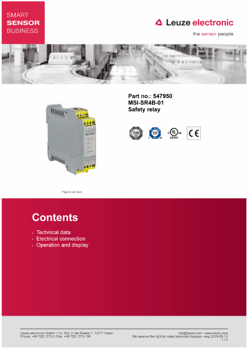
Technical dataBasic dataSeries MSI-SR4BFunctionsFunctions Automatic start/restartContactor monitoring (EDM)Cross circuit monitoringStart/restart interlock (RES), selectable Restart AutomaticManualCharacteristic parametersSIL 3 ,IEC 61508SILCL 3 ,IEC/EN 62061Performance Level (PL) e ,EN ISO 13849-1MTTF d73 years ,EN ISO 13849-1PFH D0.000000021 per hourPFH D2,1E-08 per hourPFH D, nop = 48000.0000000014 per hourPFH D, nop = 288000.0000000045 per hourPFH D, nop = 864000.000000015 per hourMission time T M20 years ,EN ISO 13849-1Category 4 ,EN ISO 13849STOP category0 ,IEC/EN 60204-1B10d at DC13 (inductive load)1,000,000 number of cyclesB10d at AC15 (inductive load)1,400,000 number of cyclesElectrical dataProtective circuit Fuse on switching output, upstream Continuous current per current path, max. 3 AInput current, max.100 mAExternal safeguarding for supply circuit200 mA delay-actionPermissible input line resistance, max.30 ΩPerformance dataSupply voltage U B24 V ,AC/DC ,-20 ... 20 %Current consumption, max.Without external loadPower consumption, max. 3 WOutputsNumber of safety-related switching outputs (OSSDs) 3 Piece(s)Safety-related switching outputsType Safety-related switching output OSSD Voltage type AC/DCSafety-related switching output 1Switching element Relay ,NOSafety-related switching output 2Switching element Relay ,NOSafety-related switching output 3Switching element Relay ,NOTimingResponse time10 msPickup delay, automatic start300 msPickup delay, manual start30 msRegression delay10 msTest pulse acceptance, max. 1 msTime window for signal sequence monitoring20 msConnectionNumber of connections 1 Piece(s) Connection 1Type of connection TerminalFunction Connection to deviceType of terminal Screw terminalNo. of pins16 -pinCable propertiesConnection cross sections0.2 to 2.5 mm²Mechanical dataDimension (W x H x L)22.5 mm x99 mm x114.1 mm Housing material Plastic ,PA66Electrical contact material Silver alloyNet weight170 gHousing color GrayType of fastening Snap-on mounting Mechanical life time10,000,000 actuation cyclesOperation and displayType of display LEDNumber of LEDs 4 Piece(s)Environmental dataAmbient temperature, operation0 ... 55 °CAmbient temperature, storage-25 ... 70 °CCertificationsDegree of protection IP 20 (terminals)IP 40 (housing)Protection class IICertifications c TÜV NRTL USc UL USTÜV SüdClassificationCustoms tariff number85371098*********27371819*********27371819ETIM 5.0EC001449ETIM 6.0EC001449Electrical connectionConnection 1Type of connection TerminalFunction Connection to deviceType of terminal Screw terminalNo. of pins16 -pinTerminal Assignment13Relay contact 1 IN23Relay contact 2 IN33Relay contact 3 IN41Signal contact INA1+24VS35Restart inputS33Sensor supply, contacts 24V OUTS22Sensor inputS12Sensor inputA20 VS34Restart automatic outputS31Sensor input14Relay contact 1 OUT24Relay contact 2 OUT34Relay contact 3 OUT42Signal contact INOperation and displayLEDsLED Display Meaning1Green, continuous light Supply voltage on2Green, continuous light Relay K1 picked up3Green, continuous light Relay K2 picked up4Yellow, continuous light Restart interlock locked。
C2000系统应用协同化开发套件v1.01高压数字电机控制套件快速引导说明书
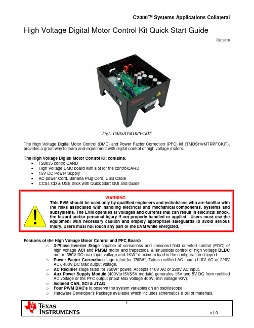
High Voltage Digital Motor Control Kit Quick Start GuideOct 2010Fig1: TMDSHVMTRPFCKITThe High Voltage Digital Motor Control (DMC) and Power Factor Correction (PFC) kit(TMDSHVMTRPFCKIT), provides a great way to learn and experiment with digital control of high voltage motors.The High Voltage Digital Motor Control Kit contains:•F28035 controlCARD•High Voltage DMC board with slot for the controlCARD•15V DC Power Supply•AC power Cord, Banana Plug Cord, USB Cable•CCS4 CD & USB Stick with Quick Start GUI and GuideWARNINGThis EVM should be used only by qualified engineers and technicians who are familiar withthe risks associated with handling electrical and mechanical components, systems andsubsystems. The EVM operates at voltages and currents that can result in electrical shock,fire hazard and/or personal injury if not properly handled or applied. Users must use theequipment with necessary caution and employ appropriate safeguards to avoid seriousinjury. Users must not touch any part of the EVM while energized.Features of the High Voltage Motor Control and PFC Board:o3-Phase Inverter Stage capable of sensorless and sensored field oriented control (FOC) of high voltage ACI and PMSM motor and trapezoidal & sinusoidal control of high voltage BLDCmotor. 350V DC max input voltage and 1KW* maximum load in the configuration shipped.o Power Factor Correction stage rated for 750W*, Takes rectified AC input (110V AC or 220V AC). 400V DC Max output voltage.o AC Rectifier stage rated for 750W* power. Accepts 110V AC or 220V AC input.o Aux Power Supply Module (400Vto15V&5V module) generates 15V and 5V DC from rectified AC voltage or the PFC output (input Max voltage 400V, min voltage 90V).o Isolated CAN, SCI & JTAGo Four PWM DAC’s to observe the system variables on an oscilloscope.o Hardware Developer’s Package available which includes schematics & bill of materials.o Open source software available through controlSUITE for each type of the motor and control type.*For detailed feature list and power ratings and safety related information refer to the kit’s HW Reference guideThe software available with the kit is pre-optimized for the motors that are available with the kit. The software is completely open source, and hence can be easily modified to tune and run a different motor. The following motors are available with the kit:AC Induction Motor (HVACIMTR)(220V , 3 phase AC, 0.25 HP)PMSM Motor (HVPMSMMTR)(200V, 3 Phase AC, 0.4KW)BLDC Motor (HVBLDCMTR)(160-170V, 3 Phase AC)Note: The BLDC motor being shipped with the kit is rated for 160V in regions having mains supply > 140V AC a step down transformer needs to be used. Otherwise the GUI would give an over voltage error and disconnect from the controller.Hardware OverviewFig2: Block Diagram for a typical motor drive system using power factor correctionFig 2, illustrates a typical motor drive system running from AC power and various blocks that make up such a system. All these power/control blocks are present on the TMDSHVMTRPFCKIT board in form of macro blocks. Below is a list of all the macro blocks names and numbers present on the board and a short description of it’s function, Fig 3, shows the location of these block on the motor control board and a few key connector location. HVDMC Main Board [Main]– Consists of controlCARD socket, communications(isoCAN) block,Instrumentation(DAC’s), QEP and CAP connection and routing of signals in b/w the macros and to the control card.AC-Power Entry [M1] – Takes input AC power from mains/wall power supply and rectifies it. This rectified voltage can then be used for input of the PFC stage or used to generate the DC bus for the inverter directly. Aux Power Supply Module [M2]– This module can take up to 400V input and generate 5V and 15V DC power. Rectified AC input can directly be connected to this module or output from the PFC stage cane be used with appropriate jumper settings.Iso-USB-to-JTAG Macro [M3] – Provided on board isolated JTAG connection through USB to the host. Can also be used for SCI(isolated) communication for connection with GUI.PFC-2PhiL Macro [M4] - Two-phase interleaved PFC stage can be used to increase efficiency of operation. Inverter2Ph-HV-3shunt Macro [M5] - Three-phase inverter, provides the inverter stage to enable control of high voltage motors.DC-PwrEntry Macro [M6] - DC power entry, used to generate the 15V, 5V and 3.3V for the board from 15V DC power supply supplied with the kit.Nomenclature : To easily find a component let’s say a jumper they are referred with their macro number in the brackets. For example, [M3]-J1 would refer to the jumper J1 located in the macro M3 and [Main]-J1 would refer to the J1 located on the board outside of the defined macro blocks.Inverter3Ph-HV-Control Card Slot PFC-2PhiL MacroAC-Power EntryAux PowerIso-USB-to-JTAG DC-PwrEntry [Main]-P1[Main]-BS1[Main]-BS5USB Cable connector3Shunt Macro [M5]C2000[M4][M1]Supply Module[M2][M3]Macro [M6]AC Power InputRectified AC Out Inv-BUS Input[Main]-TB3Terminal Block[M3]-JP1Fig3: HVDMCMTRPFCKit Board Macros Quick Start GUIThe kit comes with a GUI which provides a convenient way to evaluate the functionality of the kit and the F28035 device without having to learn and configure the underlying project software or install CCS. The interactive interface using sliders, buttons, textboxes and graphs enables easy demo of sensorless control of ACI, PMSM and BLDC Motor.Hardware SetupNote: Do not apply AC power to board before you have verified these settings!The kit ships with the control card inserted and the jumper and switch settings pre done for connecting with the GUI. However the user must ensure that these settings are valid on the board. To validate these settings and connect the motor the lid of the kit needs to be unscrewed. The lid can be screwed back once these settings are verified.1) Make sure nothing is connected to the board, and no power is being supplied to the board.2) Insert the Control card into the [Main]-J1 controlCARD connector if not already populated.4) Make sure the following jumpers & connector settings are valid i.e.a. [M3]-J4 is populatedb. [Main]-J11,J12 & J13 are populated with jumper b/w 1 and middle pinc. [Main]-J3,J4 & J5, are populatedd. [Main]-J2 is populated with a jumper b/w bridge and the middle pine. Make sure that [M6]-J6,J7,J8 ; [Main]-J9 and [M3]-J1,J3,J5 are not populatedf. Banana cable b/w [Main]-BS1 and [Main]-BS5 is installed5) Make sure that the following switches are set as described below on the F28035 control card to enableboot from flash and connection to the SCIa. SW1 is in the OFF positionb. SW2 on controlCARD, Position 1 = ON, Position 2 = ON6) Connect a USB cable from [M3]-JP1 to the host computer. [M3]-LD1 would light up indicating that theUSB is powered. Windows would then search for a driver for the device. If the computer has CCSv4 or prior versions of it installed which supported XDS100 emulator, Windows should be able to find the driver successfully. If not you would be prompted to install the driver. Installing driver for USB to serial : Do not let Microsoft search for the driver, instead browse to the following location on the USB stick drive shipped with the kit <Drive Name:\CDM 2.06.00 WHQL Certified>, windows should now be able to find the driver and would install it. If Windows still does not find the driver, you may have to repeat the process and point to the location pointed out previously. You may have to reboot the computer for the drivers to come into effect. Once installed you can check if the installation was completed properly by browsing to ControlPanel-> System->Hardware->Device Manager and looking for USB Serial Port under Ports(COM&LPT). Note this port number down.7) Connect the motor you want to spin to the terminal block [Main]-TB3 on the board, (Only the Red, Whiteand Black wire need to be connected to TB3, the Green wire is ground and should not be connected to the [Main]-TB3)8) Re-fit the Lid on the kit.9) Connect one end of the AC cord to [Main]-P1, Do not connect the other end to wall supply. Use anarrangement which allows for a switch b/w the wall supply and the board.Software SetupThe QSG GUI (HVMTRPFCKIT-GUIv1.exe) can be located in the drive that is shipped with the kit or once controlSUITE is installed at the following location:controlSUITE\developement_kits\HVMotorCtrl+PfcKit\~GUI\HVMTRPFCKIT-GUIv1.exeThe GUI is written in C# using Microsoft Visual Studio .NET with the source code located at:controlSUITE\developement_kits\HVMotorCtrl+PfcKit\~GUI\ ~SourceThe GUI requires Microsoft .NET framework 2.0 or higher to run. Please ensure that this software is installed prior to running this program.The kit ships with a F28035 Control Card which is pre-flashed with the code that enables interface to this GUI. The flashed code is optimized for running sensorless FOC on ACI and PMSM motor and sensorless trapezoidal control on BLDC motor that are available with the kit. Note that the performance of the motor with the flashed image is not a metric of quality of control and performance levels achievable using the TI DMC library. Please refer to the individual system software and corresponding literature for details. These can be downloaded through controlSUITE. The flash image can be re-flashed using CCSv4 if need be. The image can be found in the drive shipped with the kit or at the following location:controlSUITE\developement_kits\ HVMotorCtrl+PfcKit\~GUI\ HVMTRPFCKIT-GUI-FlashImagev1.outRunning the GUI1) Make sure all the jumper and connector setting are as described in the Hardware setup section.2) Browse to and double click on HVMTRPFCKIT-GUIv1.exe The GUI window should pop up (Fig 4). If thisis the first time you would have to go through a license agreement. The GUI is divided into the following sections•Motor Select Box: Allows the user to select the motor type that is connected to the board. It also notifies the type of control being used for each type of motor.•Motor Control / Status Box: This box contains sliders, textboxes, checkboxes, buttons and graphs that enable control of the motor and display various system parameters depending on the motortype selected.•Connection Box: Contains control for setting up connection with the board. Clicking on Setup Connection opens a new window which lets you select the serial port and baud rate.Connect/Disconnect switch is used to establish SCI connection with the controller or terminate the connection. A checkbox displays the status of connection i.e. whether the connection is established/ not established or broken.Note: Many variables on the GUI are referenced in per unit scale (pu). This is done as fixed point math is used by the controller to execute the control algorithm.Fig4: GUI Startup3) Now Click on “Setup Connection” and ensure the Baud Rate is set to 57600 and that the Boot onConnect Box is unchecked.4) Now select the appropriate COM port. This can be found out by going toControl Panel->System->Hardware tab->Device Manager->Ports(COM & LPT).And look for the one which is described as USB Serial Port or similar. Hit OK once done.Fig5: GUI Setup Connections5) Return to the GUI screen and now connect the other end of the AC power cord to mains/wall poweroutlet. Use an assembly such that a switch is in place between the mains supply and the board. For example this can achieved using an extension cable.6) Once the mains is connected the board would power up and you would see that the [Main]-LD1 on theboard is green (indicating power) and LD3 (Red) on the board is blinking slowly indicating that code is running on the control card.7) Now press “Connect” on the GUI window. If an incorrect image is flashed on the control card an errormessage on the bottom of the screen would be displayed. In this case it is recommended to switch of the Mains supply and reflash the control card with the correct image. Once the connection is established the LD2(Red) on the control card would start blinking and the Motor Select Panel would become active.8) After the connection is established to the controller the type of motor can be selected by clicking on themotor image. Once the motor is selected the image of the motor and type of control being used would be highlighted and the motor select panel would gray out. If the selection needs to be changed the board needs to be power cycled as the code accepts motor type only once from the GUI for safety reasons in its lifetime. In case of connect disconnect without power cycling the board the previous motor selection is remembered. Also note if BLDC motor is being used with wall supply of >140V AC a step down transformer must be used as the BLDC motor is rated for 160V, otherwise an over voltage condition flag would be displayed.9) The motor control/status box would now become active. The variables being displayed in the box wouldchange depending on the type of motor selected. Following is a description of each of these controls: •DC Bus Voltage Textbox: Textbox displays the rectified AC voltage. This voltage should be around 154V for 110V AC supply but can go as high as 180V depending on line conditions. For 220 AC line this voltage would be close to 311V.•Start / Stop Button: This button can be used to start and stop the motor. The color & text of the button changes depending on what action can be taken. Please provide for enough time for the motor to respond to the command.•Speed Reference Slider & Textbox: Speed of the motor can be varied using this slider and the textbox. The range of speed reference slider changes depending on the motor type selected. By default when the motor is started a 0.3pu speed reference is provided. To change the speed the slider can be moved or a value entered into the textbox. The textbox changes color as value is being typed depending on if it can accept that value. A value can only be entered if it is displayed as green. Once the speed ref is changed the motor ramps up to the reference speed. Time taken for the motor to reach the speed would depend on motor type. Please provide for enough time for motor to ramp up to this speed. Also note that the ramp is deliberately slow in the flashed image, and can be easily modified in the code for desired performance levels and characteristics.•Estimated Speed Textboxes: These text boxes display the speed of the motor as estimated by the sensorless algorithm. Both per unit and absolute rpm values are displayed. Note for different type of motor the rpm speed may vary for the same per unit speed reference as the maximum rated speed of the motors are different.•Park Q & Park D output Textboxes (for ACI and PMSM motors only) These two text boxes display the park Q and park D values as computed by the sensorless algorithm. These can be observed to change as the motor is loaded. Note for the PMSM motor Park D value would remain close to zero.•Graph Windows: Upto Four graph windows can display data captured from the controller.Depending on the motor type this data would change. For example for an ACI motor the graphs would display the estimated flux, estimated angle and the leg currents sensed(Fig 6). For BLDC the back EMF’s sensed would be observed, and for PMSM the Phase voltage, phase Duty, estimated angle and Alpha back emf are displayed.•AutoScale Checkbox: Check this box to autoscale the graph to get more meaningful waveforms.•Dlog Prescalar Textbox: This value is used by the Data Logging module running on the controller to sample the data for plotting. Greater this value more cycles are visible in the graph window.However as fewer points are sampled this reduces the accuracy. This value needs to be changed depending on the motor type and speed reference chosen. By default a value of 5 is pre-selected.•Graph Update Rate Select: This is the rate at which the GUI asks the controller for data to plot on the graphs. Note unless you select a rate the GUI does not ask the controller for any data and hence nothing would be plotted on the graphs. Also note that the data is captured in real time however only a small snapshot of it is displayed on the graph window.•Update Rate Select: This is the rate of how frequently the data for the textboxes, buttons and sliders is updated from the GUI to the controller and vice versa.Fig 6: GUI Running ACI Motor10) Once the start button is clicked the motor accelerates to the speed reference value and the speed loopis closed. The time taken for motor to ramp up to a particular speed would depend on motor type.Hence provide for enough time for the motor to ramp up to the speed set. The speed can be varied by moving the slider or entering value in the textbox. The motor can be stopped and started number of times. Note that each time the motor is stopped you may observe a surge in the DC bus voltage. Note: If LD2 on the control card stops blinking and the GUI stops updating, this indicates that GUI has lost connection to the board. In this case it is recommended to click on the disconnect button, wait for the GUI status to change to disconnected and then click on connect. If the motor was spinning before GUI lost connection a connect would force the motor to stop.11) The parameters in the preflashed image have been tuned for light loads over the range for DC busvoltage generated from 110V AC line or 220v AC line. The motor can be loaded and the result in case of load observed on the GUI.12) Once finished evaluating, click on the stop button to stop the motor. Once motor comes to a full stopclick on disconnect. Now Switch off/ Unplug the AC power. As the capacitors are charged the LED onthe control card may remain ON for a couple of seconds. Do not touch the board unless these LED’s go OFF. You may hear a discharging noise as the capacitors discharge.13) All future updates/enhancements to the GUI and/or Flash image would be made available throughcontrolSUITE.14) Please note that the Flash image is meant for quick demonstration purpose only. For a more detailedexplanation and understanding on the control algorithm being used and tradeoffs refer to the individual project for the motor type and control method being implemented undercontrolSUITE\developement_kits\HVMotorCtrl+PFCKit.ReferencesFor more information please refer to the following:•Download and Install ControlSUITE/controlSUITE•F28xxx User’s Guides/f28xuserguidesAfter controlSUITE install• HighVoltageMotorCtrl+PFC HW Reference Guide – provides detailed information on the High voltage motor control and PFC kit hardware.controlSUITE\development_kits\HVMotorCtrl+PfcKit\~Docs•HighVoltageMotorCtrl+PFC-HWdevPkg – a folder containing various files related to the hardware on the kit board (schematics, bill of materials, Gerber files, PCB layout, etc).controlSUITE\development_kits \HVMotorCtrl+PFCKit\~HVMotorCtrl+PfcKit_HWdevPkg\•HighVoltageMotorCtrl+PFC How to Run Guide- presents more information on the HW setup required and software installation that need to be done for using projects associated with the kit.controlSUITE\development_kits \HVMotorCtrl+PFCKit\~Docs•All the projects for different motors and sensored and sensorless implementations can be found at controlSUITE\development_kits \HVMotorCtrl+PFCKit\ HVACISensorless\ HVACISensored\ HVPMSensorless\ HVPMSensored\ HVBLDCSensorless\ HVBLDCSensored。
SINUMERIK_808D_调试手册
Siemens AG Industry Sector Postfach 48 48 90026 NÜRNBERG 德国
文件订购号: 6FC5397-4EP10-0RA0 Ⓟ 12/2012 本公司保留技术更改的权利
Copyright © Siemens AG 2012. 保留所有权利
目录
1 交付检查 ...........................................................................................................................................7
4.2
PPU 键盘功能 .................................................................................................................... 28
4.3
MCP 操作模式切换............................................................................................................. 29
合格的专业人员
本文件所属的产品/系统只允许由符合各项工作要求的合格人员进行操作。其操作必须遵照各自附带的文件说明,特 别是其中的安全及警告提示。 由于具备相关培训及经验,合格人员可以察觉本产品/系统的风险,并避免可能的危 险。
按规定使用 Siemens 产品
请注意下列说明:
商标 责任免除
警告 Siemens 产品只允许用于目录和相关技术文件中规定的使用情况。如果要使用其他公司的产品和组件,必须得到 Siemens 推荐和允许。正确的运输、储存、组装、装配、安装、调试、操作和维护是产品安全、正常运行的前 提。必须保证允许的环境条件。必须注意相关文件中的提示。
制导雷达 SITRANS LG270 四线制 Modbus 转换器版本 操作说明书

制导雷达SITRANS LG270四线制 Modbus转换器版本,带两个腔室,同轴测量探头 -196 … +280 ℃; -196 … +450 ℃操作说明书 • 04/20162PBD-51041273SITRANS LG270 - 操作说明书44296-ZH-1605273PBD-51041273SITRANS LG270 - 操作说明书44296-Z H -160527目录1关于本文献资料1.1 功能 .............................................................................................................................................................................51.2 对象 .............................................................................................................................................................................51.3 使用的标记.. (52)为了您的安全2.1 获得授权的人员.........................................................................................................................................................62.2 合规使用 .....................................................................................................................................................................62.3 谨防错误使用.............................................................................................................................................................62.4 一般安全提示.............................................................................................................................................................62.5 CE 认证 .......................................................................................................................................................................62.6 NAMUR 推荐 (63)产品说明3.1 结构 .............................................................................................................................................................................73.2 作业方式 .....................................................................................................................................................................83.3 包装、运输和仓储 ....................................................................................................................................................93.4 附件与备件 (104)安装4.1 一般提示 ...................................................................................................................................................................114.2安装提示 (11)5与供电电源和总线系统相连接5.1 准备接线 ...................................................................................................................................................................165.2 连接 ...........................................................................................................................................................................165.3 接线图 .......................................................................................................................................................................185.4 带 DISADAPT 的双腔式壳体................................................................................................................................195.5 附加电子部件...........................................................................................................................................................205.6 启动阶段 . (206)对带有显示和调整模块的传感器进行调试6.1 操作范围 ...................................................................................................................................................................216.2 使用显示和调整模块 ..............................................................................................................................................216.3 操作系统 ...................................................................................................................................................................226.4 参数化 - 快速调试 ..................................................................................................................................................236.5 参数化 - 扩展了的操作功能..................................................................................................................................236.6 对设置的参数数据的存储 .. (387)将传感器和 Modbus 接口连同 PACTware 一起投入使用7.1 连接计算机...............................................................................................................................................................397.2 通过 PACTware 设置参数.....................................................................................................................................407.3 设置仪表地址...........................................................................................................................................................417.4 通过快速调试来投入使用 ......................................................................................................................................427.5 对设置的参数数据的存储 .. (438)诊断与服务8.1 维护 ...........................................................................................................................................................................448.2 诊断储存器...............................................................................................................................................................448.3 状态报告 ...................................................................................................................................................................448.4 排除故障 ...................................................................................................................................................................488.5 更换电子插件...........................................................................................................................................................508.6 软件升级 ...................................................................................................................................................................508.7 需要维修时的步骤 .. (519)拆卸9.1 拆卸步骤 ...................................................................................................................................................................529.2废物清除 (52)4PBD-51041273SITRANS LG270 - 操作说明书44296-ZH-16052710 附件10.1 技术数据 ...................................................................................................................................................................5310.2 Modbus 的依据......................................................................................................................................................6110.3 Modbus 寄存器......................................................................................................................................................6310.4 Modbus RTU 指令 ................................................................................................................................................6510.5 Levelmaster 指令 ..................................................................................................................................................6810.6 典型的 Modbus 主机的配置................................................................................................................................7210.7 尺寸 ...........................................................................................................................................................................7710.8商标 (79)用于防爆区域的安全提示请在将仪表用于防爆应用领域时遵守专门针对防爆的安全说明。
飞思卡尔半导体公司MC33797四通道点火驱动器IC技术数据说明书
飞思卡尔半导体公司 文档编号:MC33797技术数据第6.0版,2014年2月©飞思卡尔半导体公司,2006 - 2014。
保留所有权利。
四通道点火驱动器IC四通道点火驱动器IC 是一款用于汽车安全气囊模块的完整点火诊断和部署接口。
拥有全面的诊断和系统控制功能,可实现故障安全操作。
该器件包含一个兼容串行外设接口(SPI)的8位接口,支持微处理器控制。
该器件可用于标准的四通道点火驱动器IC ,或用于高边和低边点火驱动器位于不同点火驱动器IC 时的交叉耦合状态。
高边和低边的输出驱动器均受到保护,不会受对电池或对地临时短路的影响。
限流阈值由外部电阻设置。
该器件采用SMARTMOS 技术。
特性 • 四通道高边和低边2.0 A FET 开关 • 外部可调的FET 限流功能 • 可调限流范围:0.8至2.0 A • 通过与SPI 通信实现单个通道限流检测以及定时持续时间测量 • 用于诊断和FET 开关激活的8位SPI • 高边安全传感器状态诊断 • 点火装置的电阻和电压诊断 • 点火驱动器IC 可用于交叉耦合驱动器点火应用(将高边和低边FET 开关置于不同的点火驱动器IC 上)EW 后缀(无铅) 98ARH99137A 32引脚SOICW应用 • 汽车安全气囊展开 • 安全带自动锁止• 计算机控制模型火箭点火器 • 远程发射烟花焰火表演• 采矿和建筑施工中计算机控制的雷管点火 •军用或警用武器系统图1. 33797简化应用电路图337972 模拟集成电路器件数据飞思卡尔半导体公司1 可订购部件表1. 可订购部件版本注1. 要订购以带/卷形式提供的零件,请在部件编号后面添加R2后缀。
内部功能框图33797模拟集成电路器件数据飞思卡尔半导体公司3内部功能框图图2.33797简化内部功能框图引脚连接337974 模拟集成电路器件数据飞思卡尔半导体公司引脚连接图3. 引脚功能说明表2. 引脚功能说明引脚连接33797模拟集成电路器件数据飞思卡尔半导体公司5表2. 引脚功能说明(续)电气特性最大额定值337976 模拟集成电路器件数据飞思卡尔半导体公司电气特性最大额定值表3. 最大额定值所有电压都是相对于地而言,除非另有说明。
液位计远程调试指导
854伺服液位调试培训手册1,ENSITE调试软件安装和基本操作:液位计安装完成后,确认接线正确,就可以送电了。
将ENRAF提供的调试软件ENSITE直接COPY到D盘,打开ENSITE 文件夹中的可执行文件ENSITE.EXE,按ALT+回车全屏化。
没点击SCAN后,选择1200(CIU的通讯波特率),COM1,ALL后按OK。
搜索完成后所有的现场仪表都显示在列表中,输入新的文件名,按确认就可以开始调试了。
单击ALL将所有表添加到右侧列表中,单击ENCASE,进入调试界面,按SPLIT=OFF打开显示窗口,SELECT可以任意切换罐,REQUEST是指令输入窗口,SEND送出指令。
指令送出后显示&表示成功,显示!058或者!053表示失败。
当然,调试同样可以使用手操器PET 在罐上进行。
所有指令都完全一一样。
当调试完液位计后,单击左侧的LOG,将液位计的所有设置备份到相应文件下:D:\ENSITE\DAT\文件名\罐名2,液位计基本设置:新的液位计送电后会显示+027.0000,这是出厂的设置。
输入FR停住浮子,检查DC(磁鼓周长是否和磁鼓上刻的是否一致)。
输入:W2=ENRAF2 指令输入密码DW=+.26540000E+03 预设浮子的重量(数值刻在浮子上)(D isplacer W eight)DV=+.20040000E+03 设置浮子体积(数值刻在浮子上)(D isplacer V olume)S1=+.20800000E+03 预设测量液位(I1)时钢丝张力的平衡值(S et point1)S2=+.05000000E+03 设定浮子到罐底(I2)钢丝张力的平衡值(S et point2)TA=03 新的仪表地址(原先是00)(T ransmission A ddress)TI=TK-003 输入罐的编号,空格补齐6位(T ank I dentifier)WT=EDE 力传感器保护(W ire T ension protection)ML=+000.0000 马达低限位由1米改成0。
- 1、下载文档前请自行甄别文档内容的完整性,平台不提供额外的编辑、内容补充、找答案等附加服务。
- 2、"仅部分预览"的文档,不可在线预览部分如存在完整性等问题,可反馈申请退款(可完整预览的文档不适用该条件!)。
- 3、如文档侵犯您的权益,请联系客服反馈,我们会尽快为您处理(人工客服工作时间:9:00-18:30)。
Type 4 pole safety relay
Contact configuration 2 NO + 2 NC contacts
Contact material AgSnO2
3 NO + 1 NC contacts
Coil 5 VDC 6 VDC 9 VDC 12 VDC 18 VDC 21 VDC 24 VDC 36 VDC 40 VDC 48 VDC 60 VDC 85 VDC 110 VDC 5 VDC 6 VDC 9 VDC 12 VDC 18 VDC 21 VDC 24 VDC 36 VDC 40 VDC 48 VDC 60 VDC 85 VDC 110 VDC
General Purpose Relays
Safety Relay SR4 D/M (Continued)
Other coil voltages on request
PCB layout / terminal assignment
Bottom view on solder pins
Insulation
1)
S0413-BA
please contact technical support for washing parameters
Dimensions
S0412-BH
Product key Type Contact configuration D 2 NO + 2 NC contacts M 3 NO + 1 NC contacts Contact material 4 AgSnO2 Coil Coil code = rated coil voltage (e.g. 024=24 VDC) Other types on request
Ie 3 A / Ue 250 VAC (inrush 30 A) Ie 1.5 A / Ue 250 VAC (inrush 15 A) AgSnO2 10 mA / 5 V w 100 mOhm / 1 A / 24 VDC w 20 Ohm / 10 mA / 5 VDC Mechanical endurance 10x106 cycles Rated frequency of operation with / without load 6 min-1 / 150 min-1
S0413-BC
S0413-BB
Other data
RoHS - Directive 2002/95/EC compliant as per product date code 0407 Ambient temperature range -25...+70°C Vibration resistance (function) NO / NC contact > 10 / 2 g, 10....200 Hz Shock resistance (function) NO / NC contact > 10 / 2 g, 11 ms half sine Category of protection RT III 1) Resistance to soldering heat 260°C / 5 s Relay weight 16 g Packaging unit 10 pcs
Insulation resistance coil-contact circuit Dielectric strength coil-contact circuit open contact circuit adjacent contact circuits Clearance / creepage coil-contact circuit adjacent contact circuits adjacent contact circuits (UL840) Material group of insulation parts Tracking index of relay base Insulation to IEC 60664-1 Type of insulation coil-contact circuit open contact circuit adjacent contact circuits Rated insulation voltage Pollution degree Rated voltage system Overvoltage category Insulation to EN 50178 Type of insulation coil-contact circuit adjacent contact circuits > 100x106 Ohm 4000 Vrms 1500 Vrms 2500 Vrms W 10 / 10 mm W 3 / 3.5 mm W 1.3 / 3.5 mm W IIIa CTI 250 reinforced functional basic 250 V 2 230/400 V III reinforced basic 3 NO and 1 NC contacts 2 NO and 2 NC contacts
Applications Emergency shut-off, machine control, elevator and escalator control, light barrier control
F0244-A
Approvals
V REG.-Nr. 40005334, Z E214024, T 968/EL 230.00/03
1
Datasheet Rev. EK1 Issued 2005/11 Dimensions are in mm unless otherwise specified and are shown for reference purposes only. Product specification according to IEC 61810-1. Product data, technical parameters, test conditions and processing information only to be used together with the 'Definitions' at in the ‘Schrack’ section. Specifications subject to change.
General Purpose Relays
Safety Relay SR4 D/M (Continued)
Product key SR4D4005 SR4D4006 SR4D4009 SR4D4012 SR4D4018 SR4D4021 SR4D4024 SR4D4036 SR4D4040 SR4D4048 SR4D4060 SR4D4085 SR4D4110 SR4M4005 SR4M4006 SR4M4009 SR4M4012 SR4M4018 SR4M4021 SR4M4024 SR4M4036 SR4M4040 SR4M4048 SR4M4060 SR4M4085 SR4M4110
S R 4
4ቤተ መጻሕፍቲ ባይዱ
2
Datasheet Rev. EK1 Issued 2005/11 Dimensions are in mm unless otherwise specified and are shown for reference purposes only. Product specification according to IEC 61810-1. Product data, technical parameters, test conditions and processing information only to be used together with the 'Definitions' at in the ‘Schrack’ section. Specifications subject to change.
Coil data
Rated coil voltage range DC coil Coil power DC coil Operative range 5...110 VDC appr. 800 mW 2
Coil versions, DC-coil Coil Rated Operate Release Coil Rated coil code voltage voltage voltage resistance power VDC VDC VDC Ohm mW 005 5 3.8 0.5 31+10% 806 006 6 4.5 0.6 45+10% 800 009 9 6.8 0.9 101+10% 802 012 12 9.0 1.2 180+10% 800 015 15 11.3 1.5 281+10% 801 018 18 13.5 1.8 405+10% 800 021 21 15.8 2.1 551+10% 800 024 24 18.0 2.4 720+10% 800 036 36 27.0 3.6 1620+10% 800 040 40 30.0 4.0 2000+10% 800 048 48 36.0 4.8 2880+10% 800 060 60 45.0 6.0 4500+10% 800 085 85 63.8 8.5 9031+10% 800 110 110 82.5 11.0 15125+10% 800 All figures are given for coil without preenergization, at ambient temperature +23°C
Technical data of approved types on request
