Mathematical Model of Electric Vehicle Power Consumption for Traveling and Air-Conditioning
专业英语--产品介绍
c.Press the INV key and you can raise the constant e (2.7182818) to x powers.
(4)选择合适的翻译技巧遣词造句,重述原文内容; a. Internet is of great help to our work. b.Mankind has always reverenced what Tennyson call “the useful trouble of the rain”.
4)后置定语很常见; The connecting rod, in essence, is a bar or strut with a bearing at each end, whose purpose is to transmit the piston thrust to the crankshaft. 5)名词连用 a. computer programming teaching device manual
What are the chances of a nuclear war in the near future? How many Americans would survive a nuclear attack? Would such an attack make living conditions impossible for the survivors? These and similar questions are being asked by citizens groups throughout this country as they debate the issue of arms control and nuclear disarmament.
数学模型部分词汇翻译

数学模型:[英文]:mathematical model[解释]:对于现实世界的某一特定对象,为了某个特定的目的,通过一些必要的假设和简化后所作的数学描述。
利用模型,通过数学的分析处理,能够对原型的现实性态给出深层次的解释,或预测原型未来的状况或提供处理原型的控制或优化的决策。
它是数学理论和方法用以解决现实世界实际问题的一个重要途径。
例如牛顿第二定律所描述的力和运动的关系 F = ma = md 2 s / dt 2 给出了受外力 F 作用的物体运动的距离 s ( t )与 F 的关系。
它是一个数学上的二阶微分方程,假设物体为一个质点,不存在阻力,摩擦力等的前提下描述了物体的运动与所受外力的依赖关系。
这就是动力学一个最基本的数学模型。
利用它就可以从理论上探讨大量的动力学的现象。
当代由于数学向各门学科的全面渗透,数学不仅仅是物理学的研究工具,它已成为各门学科的一个重要的研究手段,建立数学模型最重要的步骤是首先要把研究对象通过化简,归结出它的数学结构,以便于使用数学理论和方法。
由于数学模型在科学发展中的重要性,它和数学建模已经逐渐从各门学科中独立出来,成为应用数学的一个重要的方向而进入学校的教学计划。
与数学的演绎推理不同,数学模型是运用数学的语言和工具,对现实世界的信息通过假设、化简加以翻译归纳的产物,因此随着研究目的、简化方式的不同,同一个原型的数学模型可以有不同的表现方式,它可以是确定型的,也可以是随机的;可以是连续型的,也可以是离散的。
因此对于同一个原型,可以使用不同的数学分支,通过相应的模型进行研究。
当然通过数学抽象出来的模型较之原型有更宽的覆盖面,甚至于能够描述不同学科有关对象的变化关系。
由于现实世界的复杂性,科学技术发展到今天,还不能给出普遍适用的建立数学模型的准则和技巧。
在一些使用模型较多的研究领域内,已经开始形成了自己的数学模型及建模体系,例如种群生态学中的数学模型,经济学中的数学模型,天气预报的数学模型,当然也包括理论力学——作为物理中运动和力学的数学模型。
插电式混合动力汽车控制策略与建模
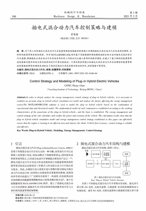
106机械设计与制造Machinery Design & Manufacture第3期2021年3月插电式混合动力汽车控制策略与建模宫唤春(燕京理工学院,北京065201)摘要:为了深入分析插电式混合动力汽车能量管理控制策略就需要建立准确的插电式混合动力汽车仿真测试模型,分析影响能量管理系统的因素。
利用M A T L A B/S I M U L I N K软件基于实验数据和理论模型相结合的方法对插电式混合动力汽车建模,根据插电式混合动力汽车传动系部件的工作特征对应建立各部件的数学模型,并建立了基于规则的能量管理控制策略对整车的动力性与经济性进行计算仿真验证,计算结果表明建立的插电式混合动力汽车仿真糢型和能量管理控制策略能够有效确保发动机处于高效区域运行并改善整车燃油经济性,控制策略可靠有效。
关键词:插电式混合动力汽车;建模;能量管理;控制策略中图分类号:T H16文献标识码:A文章编号:1001-3997(2021)03-0106-04Control Strategy and Modeling of Plug-in Hybrid Electric VehiclesGONG Huan-chun(Yanching Institute of Technology, Beijing 065201, China)Abstract :/n order to deeply analyze the energy management control strategy o f plug-in hybrid vehicles, it is necessary to establish an accurate plug-in hybrid vehicle simulation test model and analyze the factors affecting the energy management systerruThe M A T L A B/S I M U L I N K software is used to model the p lu g—in hybrid vehicle based on the combination of experimented data and theoretical model. The mathematical model o f each component is established according to the working characteristics o f the powertrain o f the p lu g-in hybrid vehicle y and the basis is established. The energy management and control strategy o f the rule calculates and verifies the power and economy o f the vehicle. The calculation results show that the plug—in hybrid vehicle simulation model and energy management control strategy established in this paper can effectively ensure that the engine is running in an efficient area and improve the whole. Vehicle fu el economy, control strategy is reliableand effective.Key Words:Plug-in Hybrid Vehicle; Modeling; Energy Management; Control Strategyl引言插电式混合动力汽车(Plug-in Hybrid Electric Vehicle, P H E V)是基于传统混合动力汽车衍生出的一种车辆,该类型汽车可以直 接接人电网进行充电,纯电动模式下续驶里程更远,同时统发动 机更省油等优点,已经成为电动汽车领域重点研发的产品之一插电式混合动力汽车对动力传动系统的设计及能量管理系统控制等要求较高从而使得其工作模式与传动混合动力汽车相比更为复杂。
mathematical modelling and analysis
mathematical modelling and analysis 数学模型和分析是数学领域中重要的分支。
数学模型是指将实际问题抽象成数学形式,用数学语言和符号表达出来,从而可以对问题进行分析和解决。
数学分析则是指运用数学方法对数学模型进行研究和求解的过程。
数学模型可以应用于各个领域,如物理、生物、经济、工程等。
其作用在于将实际问题抽象成为更为简洁、清晰的数学形式,以便更好地理解问题。
对于物理问题,数学模型可以用来描述物体的运动、热力学过程等;对于生物问题,可以用来描述生物体内的生理过程、遗传变异等;对于经济问题,可以用来描述市场供求关系、企业经营等。
数学模型的应用覆盖面非常广泛,可以帮助我们更好地理解自然和社会现象。
数学分析则是对数学模型进行研究和求解的过程。
在数学分析中,我们需要运用各种数学方法和工具,例如微积分、差分方程、统计分析等,对数学模型进行求解和分析。
通过对数学模型的分析,我们可以预测未来的趋势、优化设计方案、提高生产效率等。
数学模型和分析的应用已经深入到各个领域中,这与数学的广泛性和深度相关。
正是因为数学的广泛性和深度,它才能够应用于各个领域,进一步推动各个领域的发展。
总之,数学模型和分析是数学领域中非常重要的分支。
它们的应用覆盖面非常广泛,可以帮助我们更好地理解和解决实际问题。
与此同时,数学模型和分析也推动了数学领域的发展。
未来,随着科技的
不断进步和社会的不断发展,数学模型和分析的应用也将会不断拓展和深入。
Advanced Mathematical Modeling Techniques
Advanced Mathematical ModelingTechniquesIn the realm of scientific inquiry and problem-solving, the application of advanced mathematical modeling techniques stands as a beacon of innovation and precision. From predicting the behavior of complex systems to optimizing processes in various fields, these techniques serve as invaluable tools for researchers, engineers, and decision-makers alike. In this discourse, we delve into the intricacies of advanced mathematical modeling techniques, exploring their principles, applications, and significance in modern society.At the core of advanced mathematical modeling lies the fusion of mathematical theory with computational algorithms, enabling the representation and analysis of intricate real-world phenomena. One of the fundamental techniques embraced in this domain is differential equations, serving as the mathematical language for describing change and dynamical systems. Whether in physics, engineering, biology, or economics, differential equations offer a powerful framework for understanding the evolution of variables over time. From classical ordinary differential equations (ODEs) to their more complex counterparts, such as partial differential equations (PDEs), researchers leverage these tools to unravel the dynamics of phenomena ranging from population growth to fluid flow.Beyond differential equations, advanced mathematical modeling encompasses a plethora of techniques tailored to specific applications. Among these, optimization theory emerges as a cornerstone, providing methodologies to identify optimal solutions amidst a multitude of possible choices. Whether in logistics, finance, or engineering design, optimization techniques enable the efficient allocation of resources, the maximization of profits, or the minimization of costs. From linear programming to nonlinear optimization and evolutionary algorithms, these methods empower decision-makers to navigate complex decision landscapes and achieve desired outcomes.Furthermore, stochastic processes constitute another vital aspect of advanced mathematical modeling, accounting for randomness and uncertainty in real-world systems. From Markov chains to stochastic differential equations, these techniques capture the probabilistic nature of phenomena, offering insights into risk assessment, financial modeling, and dynamic systems subjected to random fluctuations. By integrating probabilistic elements into mathematical models, researchers gain a deeper understanding of uncertainty's impact on outcomes, facilitating informed decision-making and risk management strategies.The advent of computational power has revolutionized the landscape of advanced mathematical modeling, enabling the simulation and analysis of increasingly complex systems. Numerical methods play a pivotal role in this paradigm, providing algorithms for approximating solutions to mathematical problems that defy analytical treatment. Finite element methods, finite difference methods, and Monte Carlo simulations are but a few examples of numerical techniques employed to tackle problems spanning from structural analysis to option pricing. Through iterative computation and algorithmic refinement, these methods empower researchers to explore phenomena with unprecedented depth and accuracy.Moreover, the interdisciplinary nature of advanced mathematical modeling fosters synergies across diverse fields, catalyzing innovation and breakthroughs. Machine learning and data-driven modeling, for instance, have emerged as formidable allies in deciphering complex patterns and extracting insights from vast datasets. Whether in predictive modeling, pattern recognition, or decision support systems, machine learning algorithms leverage statistical techniques to uncover hidden structures and relationships, driving advancements in fields as diverse as healthcare, finance, and autonomous systems.The application domains of advanced mathematical modeling techniques are as diverse as they are far-reaching. In the realm of healthcare, mathematical models underpin epidemiological studies, aiding in the understanding and mitigation of infectious diseases. From compartmental models like the SIR model to agent-based simulations, these tools inform public health policies and intervention strategies, guiding efforts to combat pandemics and safeguard populations.In the domain of climate science, mathematical models serve as indispensable tools for understanding Earth's complex climate system and projecting future trends. Coupling atmospheric, oceanic, and cryospheric models, researchers simulate the dynamics of climate variables, offering insights into phenomena such as global warming, sea-level rise, and extreme weather events. By integrating observational data and physical principles, these models enhance our understanding of climate dynamics, informing mitigation and adaptation strategies to address the challenges of climate change.Furthermore, in the realm of finance, mathematical modeling techniques underpin the pricing of financial instruments, the management of investment portfolios, and the assessment of risk. From option pricing models rooted in stochastic calculus to portfolio optimization techniques grounded in optimization theory, these tools empower financial institutions to make informed decisions in a volatile and uncertain market environment. By quantifying risk and return profiles, mathematical models facilitate the allocation of capital, the hedging of riskexposures, and the management of investment strategies, thereby contributing to financial stability and resilience.In conclusion, advanced mathematical modeling techniques represent a cornerstone of modern science and engineering, providing powerful tools for understanding, predicting, and optimizing complex systems. From differential equations to optimization theory, from stochastic processes to machine learning, these techniques enable researchers and practitioners to tackle a myriad of challenges across diverse domains. As computational capabilities continue to advance and interdisciplinary collaborations flourish, the potential for innovation and discovery in the realm of mathematical modeling knows no bounds. By harnessing the power of mathematics, computation, and data, we embark on a journey of exploration and insight, unraveling the mysteries of the universe and shaping the world of tomorrow.。
机械专业英语词汇-中英文对照

机械专业英语词汇 陶瓷 ceramics合成纤维 synthetic fibre电化学腐蚀 electrochemical corrosion 车架 automotive chassis 悬架 suspension 转向器 redirector 变速器 speed changer 板料冲压 sheet metal parts 孔加工 spot facing machining 车间 workshop 工程技术人员 engineer 气动夹紧 pneuma lock数学模型 mathematical model 画法几何 descriptive geometry 机械制图 Mechanical drawing 投影 projection 视图 view剖视图 profile chart标准件 standard component 零件图 part drawing 装配图 assembly drawing 尺寸标注 size marking技术要求 technical requirements 刚度 rigidity 内力 internal force 位移 displacement 截面 section疲劳极限 fatigue limit 断裂 fracture塑性变形 plastic distortion脆性材料 brittleness material 刚度准则 rigidity criterion 垫圈 washer 垫片 spacer直齿圆柱齿轮 straight toothed spur gear 斜齿圆柱齿轮 helical-spur gear 直齿锥齿轮 straight bevel gear 运动简图 kinematic sketch 齿轮齿条 pinion and rack 蜗杆蜗轮 worm and worm gear 虚约束 passive constraint 曲柄 crank 摇杆 rackerUn Re gi st er ed凸轮 cams共轭曲线 conjugate curve 范成法 generation method 定义域 definitional domain 值域 range导数\\微分 differential coefficient 求导 derivation定积分 definite integral 不定积分 indefinite integral 曲率 curvature偏微分 partial differential 毛坯 rough游标卡尺 slide caliper 千分尺 micrometer calipers 攻丝 tap二阶行列式 second order determinant 逆矩阵 inverse matrix 线性方程组 linear equations 概率 probability随机变量 random variable排列组合 permutation and combination 气体状态方程 equation of state of gas 动能 kinetic energy 势能 potential energy机械能守恒 conservation of mechanical energy动量 momentum 桁架 truss 轴线 axes 余子式 cofactor逻辑电路 logic circuit触发器 flip-flop脉冲波形 pulse shape数模 digital analogy液压传动机构 fluid drive mechanism 机械零件 mechanical parts 淬火冷却 quench 淬火 hardening 回火 tempering调质 hardening and tempering 磨粒 abrasive grain 结合剂 bonding agent 砂轮 grinding wheelUn Re gi st er ed后角 clearance angle 龙门刨削 planing 主轴 spindle 主轴箱 headstock 卡盘 chuck加工中心 machining center 车刀 lathe tool 车床 lathe 钻削 镗削 bore 车削 turning 磨床 grinder 基准 benchmark 钳工 locksmith 锻 forge 压模 stamping 焊 weld拉床 broaching machine 拉孔 broaching 装配 assembling 铸造 found流体动力学 fluid dynamics 流体力学 fluid mechanics 加工 machining液压 hydraulic pressure 切线 tangent机电一体化 mechanotronics mechanical-electrical integration 气压 air pressure pneumatic pressure 稳定性 stability 介质 medium液压驱动泵 fluid clutch液压泵 hydraulic pump阀门 valve失效 invalidation 强度 intensity 载荷 load 应力 stress安全系数 safty factor 可靠性 reliability 螺纹 thread 螺旋 helix 键 spline 销 pin滚动轴承 rolling bearing 滑动轴承 sliding bearingUn Re gi st er ed弹簧 spring制动器 arrester brake 十字结联轴节 crosshead 联轴器 coupling 链 chain 皮带 strap精加工 finish machining 粗加工 rough machining 变速箱体 gearbox casing 腐蚀 rust 氧化 oxidation 磨损 wear 耐用度 durability 随机信号 random signal 离散信号 discrete signal 超声传感器 ultrasonic sensor 集成电路 integrate circuit 挡板 orifice plate 残余应力 residual stress 套筒 sleeve 扭力 torsion冷加工 cold machining 电动机 electromotor 汽缸 cylinder过盈配合 interference fit 热加工 hotwork 摄像头 CCD camera 倒角 rounding chamfer优化设计 optimal design工业造型设计 industrial moulding design有限元 finite element滚齿 hobbing插齿 gear shaping伺服电机 actuating motor 铣床 milling machine 钻床 drill machine 镗床 boring machine 步进电机 stepper motor 丝杠 screw rod 导轨 lead rail 组件 subassembly可编程序逻辑控制器 Programmable Logic Controller PLC 电火花加工 electric spark machining电火花线切割加工 electrical discharge wire - cuttingUn Re gi st er ed相图 phase diagram 热处理 heat treatment固态相变 solid state phase changes有色金属 nonferrous metal 陶瓷 ceramics合成纤维 synthetic fibre电化学腐蚀 electrochemical corrosion 车架 automotive chassis 悬架 suspension 转向器 redirector 变速器 speed changer 板料冲压 sheet metal parts 孔加工 spot facing machining 车间 workshop 工程技术人员 engineer 气动夹紧 pneuma lock 数学模型 mathematical model 画法几何 descriptive geometry 机械制图 Mechanical drawing 投影 projection 视图 view剖视图 profile chart 标准件 standard component 零件图 part drawing 装配图 assembly drawing 尺寸标注 size marking技术要求 technical requirements 刚度 rigidity内力 internal force位移 displacement截面 section疲劳极限 fatigue limit 断裂 fracture塑性变形 plastic distortion 脆性材料 brittleness material 刚度准则 rigidity criterion 垫圈 washer 垫片 spacer直齿圆柱齿轮 straight toothed spur gear 斜齿圆柱齿轮 helical-spur gear 直齿锥齿轮 straight bevel gear 运动简图 kinematic sketch 齿轮齿条 pinion and rack 蜗杆蜗轮 worm and worm gearUn Re gi st er ed虚约束 passive constraint 曲柄 crank 摇杆 racker 凸轮 cams共轭曲线 conjugate curve 范成法 generation method 定义域 definitional domain 值域 range导数\\微分 differential coefficient 求导 derivation 定积分 definite integral 不定积分 indefinite integral 曲率 curvature偏微分 partial differential 毛坯 rough游标卡尺 slide caliper 千分尺 micrometer calipers 攻丝 tap二阶行列式 second order determinant 逆矩阵 inverse matrix 线性方程组 linear equations 概率 probability随机变量 random variable排列组合 permutation and combination 气体状态方程 equation of state of gas 动能 kinetic energy 势能 potential energy机械能守恒 conservation of mechanical energy 动量 momentum 桁架 truss 轴线 axes余子式 cofactor逻辑电路 logic circuit 触发器 flip-flop脉冲波形 pulse shape 数模 digital analogy液压传动机构 fluid drive mechanism 机械零件 mechanical parts 淬火冷却 quench 淬火 hardening 回火 tempering调质 hardening and tempering 磨粒 abrasive grainUn Re gi st er ed结合剂 bonding agent 砂轮 grinding wheelAssembly line 组装线 Layout 布置图Conveyer 流水线物料板 Rivet table 拉钉机 Rivet gun 拉钉枪 Screw driver 起子Pneumatic screw driver 气动起子 worktable 工作桌 OOBA 开箱检查 fit together 组装在一起 fasten 锁紧(螺丝) fixture 夹具(治具) pallet 栈板 barcode 条码barcode scanner 条码扫描器 fuse together 熔合 fuse machine 热熔机 repair 修理 operator 作业员 QC 品管 supervisor 课长 ME 制造工程师 MT 制造生技cosmetic inspect 外观检查 inner parts inspect 内部检查 thumb screw 大头螺丝 lbs. inch 镑、英寸 EMI gasket 导电条 front plate 前板 rear plate 后板 chassis 基座 bezel panel 面板 power button 电源按键 reset button 重置键Hi-pot test of SPS 高源高压测试 Voltage switch of SPS 电源电压接拉键 sheet metal parts 冲件 plastic parts 塑胶件 SOP 制造作业程序material check list 物料检查表 work cell 工作间 trolley 台车Un Re gi st er edsub-line 支线 left fork 叉车personnel resource department 人力资源部 production department 生产部门 planning department 企划部 QC Section 品管科 stamping factory 冲压厂 painting factory 烤漆厂 molding factory 成型厂 common equipment 常用设备 uncoiler and straightener 整平机 punching machine 冲床 robot 机械手hydraulic machine 油压机 lathe 车床planer |plein|刨床 miller 铣床 grinder 磨床linear cutting 线切割 electrical sparkle 电火花 welder 电焊机staker=reviting machine 铆合机 position 职务 president 董事长 general manager 总经理 special assistant manager 特助 factory director 厂长department director 部长deputy manager | =vice manager 副理section supervisor 课长deputy section supervisor =vice section superisor 副课长 group leader/supervisor 组长 line supervisor 线长 assistant manager 助理to move, to carry, to handle 搬运 be put in storage 入库 pack packing 包装 to apply oil 擦油 to file burr 锉毛刺 final inspection 终检 to connect material 接料 to reverse material 翻料 wet station 沾湿台Un Re gi st er edcleaning cloth 抹布 to load material 上料 to unload material 卸料to return material/stock to 退料 scraped |\\'skr?pid|报废 scrape ..v.刮;削deficient purchase 来料不良 manufacture procedure 制程deficient manufacturing procedure 制程不良 oxidation |\\' ksi\\'dei?n|氧化 scratch 刮伤 dents 压痕defective upsiding down 抽芽不良 defective to staking 铆合不良 embedded lump 镶块feeding is not in place 送料不到位 stamping-missing 漏冲 production capacity 生产力 education and training 教育与训练 proposal improvement 提案改善 spare parts=buffer 备件 forklift 叉车trailer=long vehicle 拖板车 compound die 合模 die locker 锁模器pressure plate=plate pinch 压板 bolt 螺栓administration/general affairs dept 总务部 automatic screwdriver 电动启子 thickness gauge 厚薄规 gauge(or jig)治具power wire 电源线 buzzle 蜂鸣器defective product label 不良标签 identifying sheet list 标示单 location 地点present members 出席人员 subject 主题 conclusion 结论 decision items 决议事项responsible department 负责单位 pre-fixed finishing date 预定完成日approved by / checked by / prepared by 核准/审核/承办Un Re gi st er edPCE assembly production schedule sheet PCE 组装厂生产排配表 model 机锺 work order 工令 revision 版次 remark 备注production control confirmation 生产确认 checked by 初审 approved by 核准 department 部门stock age analysis sheet 库存货龄分析表 on-hand inventory 现有库存 available material 良品可使用 obsolete material 良品已呆滞to be inspected or reworked 待验或重工 total 合计cause description 原因说明 part number/ P/N 料号 type 形态item/group/class 类别 quality 品质prepared by 制表 notes 说明year-end physical inventory difference analysis sheet 年终盘点差异分析表physical inventory 盘点数量 physical count quantity 帐面数量 difference quantity 差异量 cause analysis 原因分析 raw materials 原料 materials 物料finished product 成品semi-finished product 半成品 packing materials 包材good product/accepted goods/ accepted parts/good parts 良品 defective product/non-good parts 不良品 disposed goods 处理品 warehouse/hub 仓库 on way location 在途仓 oversea location 海外仓spare parts physical inventory list 备品盘点清单 spare molds location 模具备品仓 skid/pallet 栈板 tox machine 自铆机 wire EDM 线割 EDM 放电机 coil stock 卷料Un Re gi st er edsheet stock 片料 tolerance 工差 score=groove 压线 cam block 滑块 pilot 导正筒 trim 剪外边 pierce 剪内边 drag form 压锻差pocket for the punch head 挂钩槽 slug hole 废料孔 feature die 公母模 expansion dwg 展开图 radius 半径 shim(wedge)楔子 torch-flame cut 火焰切割 set screw 止付螺丝 form block 折刀 stop pin 定位销round pierce punch=die button 圆冲子 shape punch=die insert 异形子 stock locater block 定位块 under cut=scrap chopper 清角 active plate 活动板 baffle plate 挡块 cover plate 盖板 male die 公模 female die 母模 groove punch 压线冲子air-cushion eject-rod 气垫顶杆spring-box eject-plate 弹簧箱顶板bushing block 衬套insert 入块club car 高尔夫球车 capability 能力 parameter 参数 factor 系数phosphate 皮膜化成 viscosity 涂料粘度 alkalidipping 脱脂 main manifold 主集流脉 bezel 斜视规 blanking 穿落模 dejecting 顶固模demagnetization 去磁;消磁Un Re gi st er edhigh-speed transmission 高速传递 heat dissipation 热传 rack 上料 degrease 脱脂 rinse 水洗 alkaline etch 龄咬 desmut 剥黑膜 D.I. rinse 纯水次 Chromate 铬酸处理 Anodize 阳性处理 seal 封孔 revision 版次part number/P/N 料号 good products 良品 scraped products 报放心品 defective products 不良品 finished products 成品 disposed products 处理品 barcode 条码 flow chart 流程表单 assembly 组装 stamping 冲压 molding 成型spare parts=buffer 备品 coordinate 座标 dismantle the die 折模 auxiliary fuction 辅助功能 poly-line 多义线 heater band 加热片thermocouple 热电偶 sand blasting 喷沙 grit 砂砾derusting machine 除锈机 degate 打浇口 dryer 烘干机 induction 感应 induction light 感应光response=reaction=interaction 感应 ram 连杆edge finder 巡边器 concave 凸 convex 凹 short 射料不足 nick 缺口 speck 瑕??Un Re gi st er edsplay 银纹 gas mark 焦痕 delamination 起鳞 cold slug 冷块 blush 导色 gouge 沟槽;凿槽 satin texture 段面咬花 witness line 证示线 patent 专利 grit 沙砾granule=peuet=grain 细粒 grit maker 抽粒机 cushion 缓冲 magnalium 镁铝合金 magnesium 镁金 metal plate 钣金 lathe 车 mill 锉 plane 刨 grind 磨 drill 铝 boring 镗 blinster 气泡 fillet 镶;嵌边through-hole form 通孔形式 voller pin formality 滚针形式 cam driver 铡楔 shank 摸柄 crank shaft 曲柄轴augular offset 角度偏差 velocity 速度production tempo 生产进度现状 torque 扭矩spline=the multiple keys 花键 quenching 淬火 tempering 回火 annealing 退火 carbonization 碳化tungsten high speed steel 钨高速的 moly high speed steel 钼高速的 organic solvent 有机溶剂 bracket 小磁导 liaison 联络单 volatile 挥发性Un Re gi st er edion 离子 titrator 滴定仪 beacon 警示灯 coolant 冷却液 crusher 破碎机阿基米德蜗杆 Archimedes worm 安全系数 safety factor; factor of safety 安全载荷 safe load 凹面、凹度 concavity 扳手 wrench 板簧 flat leaf spring 半圆键 woodruff key 变形 deformation 摆杆 oscillating bar摆动从动件 oscillating follower摆动从动件凸轮机构 cam with oscillating follower 摆动导杆机构 oscillating guide-bar mechanism 摆线齿轮 cycloidal gear 摆线齿形 cycloidal tooth profile 摆线运动规律 cycloidal motion 摆线针轮 cycloidal-pin wheel 包角 angle of contact 保持架 cage背对背安装 back-to-back arrangement 背锥 back cone ; normal cone 背锥角 back angle背锥距 back cone distance 比例尺 scale比热容 specific heat capacity闭式链 closed kinematic chain闭链机构 closed chain mechanism 臂部 arm变频器 frequency converters变频调速 frequency control of motor speed 变速 speed change变速齿轮 change gear change wheel 变位齿轮 modified gear变位系数 modification coefficient 标准齿轮 standard gear 标准直齿轮 standard spur gear 表面质量系数 superficial mass factor表面传热系数 surface coefficient of heat transfer 表面粗糙度 surface roughnessUn Re gi st er ed并联式组合 combination in parallel 并联机构 parallel mechanism并联组合机构 parallel combined mechanism 并行工程 concurrent engineering 并行设计 concurred design, CD 不平衡相位 phase angle of unbalance 不平衡 imbalance (or unbalance) 不平衡量 amount of unbalance 不完全齿轮机构 intermittent gearing 波发生器 wave generator 波数 number of waves 补偿 compensation参数化设计 parameterization design, PD 残余应力 residual stress操纵及控制装置 operation control device 槽轮 Geneva wheel槽轮机构 Geneva mechanism ; Maltese cross 槽数 Geneva numerate 槽凸轮 groove cam 侧隙 backlash差动轮系 differential gear train差动螺旋机构 differential screw mechanism 差速器 differential常用机构 conventional mechanism; mechanism in common use车床 lathe承载量系数 bearing capacity factor 承载能力 bearing capacity 成对安装 paired mounting尺寸系列 dimension series 齿槽 tooth space 齿槽宽 spacewidth 齿侧间隙 backlash 齿顶高 addendum齿顶圆 addendum circle 齿根高 dedendum 齿根圆 dedendum circle 齿厚 tooth thickness 齿距 circular pitch 齿宽 face width 齿廓 tooth profile 齿廓曲线 tooth curve 齿轮 gear齿轮变速箱 speed-changing gear boxes 齿轮齿条机构 pinion and rackUn Re gi st er ed齿轮插刀 pinion cutter; pinion-shaped shaper cutter 齿轮滚刀 hob ,hobbing cutter 齿轮机构 gear 齿轮轮坯 blank 齿轮传动系 pinion unit 齿轮联轴器 gear coupling 齿条传动 rack gear 齿数 tooth number 齿数比 gear ratio 齿条 rack齿条插刀 rack cutter; rack-shaped shaper cutter 齿形链、无声链 silent chain 齿形系数 form factor齿式棘轮机构 tooth ratchet mechanism 插齿机 gear shaper 重合点 coincident points 重合度 contact ratio 冲床 punch传动比 transmission ratio, speed ratio 传动装置 gearing; transmission gear 传动系统 driven system 传动角 transmission angle 传动轴 transmission shaft 串联式组合 combination in series串联式组合机构 series combined mechanism 串级调速 cascade speed control 创新 innovation creation 创新设计 creation design垂直载荷、法向载荷 normal load 唇形橡胶密封 lip rubber seal磁流体轴承 magnetic fluid bearing从动带轮 driven pulley从动件 driven link, follower从动件平底宽度 width of flat-face 从动件停歇 follower dwell 从动件运动规律 follower motion 从动轮 driven gear 粗线 bold line粗牙螺纹 coarse thread 大齿轮 gear wheel 打包机 packer 打滑 slipping 带传动 belt driving 带轮 belt pulleyUn Re gi st er ed带式制动器 band brake 单列轴承 single row bearing单向推力轴承 single-direction thrust bearing 单万向联轴节 single universal joint 单位矢量 unit vector当量齿轮 equivalent spur gear; virtual gear当量齿数 equivalent teeth number; virtual number of teeth 当量摩擦系数 equivalent coefficient of friction 当量载荷 equivalent load 刀具 cutter 导数 derivative 倒角 chamfer导热性 conduction of heat 导程 lead导程角 lead angle等加等减速运动规律 parabolic motion; constant acceleration and deceleration motion 等速运动规律 uniform motion; constant velocity motion 等径凸轮 conjugate yoke radial cam 等宽凸轮 constant-breadth cam 等效构件 equivalent link 等效力 equivalent force等效力矩 equivalent moment of force 等效量 equivalent 等效质量 equivalent mass等效转动惯量 equivalent moment of inertia等效动力学模型 dynamically equivalent model 底座 chassis 低副 lower pair点划线 chain dotted line (疲劳)点蚀 pitting 垫圈 gasket垫片密封 gasket seal碟形弹簧 belleville spring 顶隙 bottom clearance定轴轮系 ordinary gear train; gear train with fixed axes 动力学 dynamics 动密封 kinematical seal 动能 dynamic energy 动力粘度 dynamic viscosity 动力润滑 dynamic lubrication 动平衡 dynamic balance动平衡机 dynamic balancing machine 动态特性 dynamic characteristics 动态分析设计 dynamic analysis designUn Re gi st er ed动压力 dynamic reaction 动载荷 dynamic load 端面 transverse plane端面参数 transverse parameters 端面齿距 transverse circular pitch 端面齿廓 transverse tooth profile 端面重合度 transverse contact ratio 端面模数 transverse module端面压力角 transverse pressure angle 锻造 forge对称循环应力 symmetry circulating stress 对心滚子从动件 radial (or in-line ) roller follower 对心直动从动件 radial (or in-line ) translating follower 对心移动从动件 radial reciprocating follower对心曲柄滑块机构 in-line slider-crank (or crank-slider) mechanism 多列轴承 multi-row bearing 多楔带 poly V-belt多项式运动规律 polynomial motion 多质量转子 rotor with several masses 惰轮 idle gear 额定寿命 rating life 额定载荷 load rating II 级杆组 dyad发生线 generating line 发生面 generating plane 法面 normal plane法面参数 normal parameters 法面齿距 normal circular pitch 法面模数 normal module法面压力角 normal pressure angle法向齿距 normal pitch法向齿廓 normal tooth profile法向直廓蜗杆 straight sided normal worm 法向力 normal force反馈式组合 feedback combining反向运动学 inverse ( or backward) kinematics 反转法 kinematic inversion 反正切 Arctan范成法 generating cutting 仿形法 form cutting方案设计、概念设计 concept design, CD 防振装置 shockproof device 飞轮 flywheel飞轮矩 moment of flywheelUn Re gi st er ed非标准齿轮 nonstandard gear 非接触式密封 non-contact seal非周期性速度波动 aperiodic speed fluctuation 非圆齿轮 non-circular gear 粉末合金 powder metallurgy分度线 reference line; standard pitch line分度圆 reference circle; standard (cutting) pitch circle 分度圆柱导程角 lead angle at reference cylinder 分度圆柱螺旋角 helix angle at reference cylinder 分母 denominator 分子 numerator分度圆锥 reference cone; standard pitch cone 分析法 analytical method封闭差动轮系 planetary differential 复合铰链 compound hinge 复合式组合 compound combining复合轮系 compound (or combined) gear train 复合平带 compound flat belt 复合应力 combined stress复式螺旋机构 Compound screw mechanism 复杂机构 complex mechanism 杆组 Assur group 干涉 interference刚度系数 stiffness coefficient 刚轮 rigid circular spline 钢丝软轴 wire soft shaft刚体导引机构 body guidance mechanism 刚性冲击 rigid impulse (shock) 刚性转子 rigid rotor刚性轴承 rigid bearing刚性联轴器 rigid coupling高度系列 height series高速带 high speed belt 高副 higher pair格拉晓夫定理 Grashoff`s law 根切 undercutting公称直径 nominal diameter 高度系列 height series 功 work工况系数 application factor 工艺设计 technological design 工作循环图 working cycle diagram 工作机构 operation mechanism 工作载荷 external loadsUn Re gi st er ed工作空间 working space 工作应力 working stress 工作阻力 effective resistance工作阻力矩 effective resistance moment 公法线 common normal line 公共约束 general constraint 公制齿轮 metric gears 功率 power功能分析设计 function analyses design 共轭齿廓 conjugate profiles 共轭凸轮 conjugate cam 构件 link 鼓风机 blower固定构件 fixed link; frame 固体润滑剂 solid lubricant 关节型操作器 jointed manipulator 惯性力 inertia force惯性力矩 moment of inertia ,shaking moment 惯性力平衡 balance of shaking force 惯性力完全平衡 full balance of shaking force 惯性力部分平衡 partial balance of shaking force 惯性主矩 resultant moment of inertia 惯性主失 resultant vector of inertia 冠轮 crown gear广义机构 generation mechanism 广义坐标 generalized coordinate 轨迹生成 path generation 轨迹发生器 path generator 滚刀 hob 滚道 raceway滚动体 rolling element滚动轴承 rolling bearing滚动轴承代号 rolling bearing identification code 滚针 needle roller滚针轴承 needle roller bearing 滚子 roller滚子轴承 roller bearing 滚子半径 radius of roller 滚子从动件 roller follower 滚子链 roller chain滚子链联轴器 double roller chain coupling 滚珠丝杆 ball screw滚柱式单向超越离合器 roller clutch 过度切割 undercuttingUn Re gi st er ed函数发生器 function generator 函数生成 function generation 含油轴承 oil bearing 耗油量 oil consumption耗油量系数 oil consumption factor 赫兹公式 H. Hertz equation合成弯矩 resultant bending moment 合力 resultant force合力矩 resultant moment of force 黑箱 black box 横坐标 abscissa互换性齿轮 interchangeable gears 花键 spline滑键、导键 feather key 滑动轴承 sliding bearing 滑动率 sliding ratio 滑块 slider环面蜗杆 toroid helicoids worm 环形弹簧 annular spring缓冲装置 shocks; shock-absorber 灰铸铁 grey cast iron 回程 return回转体平衡 balance of rotors 混合轮系 compound gear train 积分 integrate机电一体化系统设计 mechanical-electrical integration system design 机构 mechanism机构分析 analysis of mechanism 机构平衡 balance of mechanism 机构学 mechanism机构运动设计 kinematic design of mechanism机构运动简图 kinematic sketch of mechanism 机构综合 synthesis of mechanism 机构组成 constitution of mechanism 机架 frame, fixed link 机架变换 kinematic inversion 机器 machine 机器人 robot机器人操作器 manipulator 机器人学 robotics技术过程 technique process技术经济评价 technical and economic evaluation 技术系统 technique system 机械 machineryUn Re gi st er ed机械创新设计 mechanical creation design, MCD 机械系统设计 mechanical system design, MSD 机械动力分析 dynamic analysis of machinery 机械动力设计 dynamic design of machinery 机械动力学 dynamics of machinery 机械的现代设计 modern machine design 机械系统 mechanical system 机械利益 mechanical advantage 机械平衡 balance of machinery 机械手 manipulator机械设计 machine design; mechanical design 机械特性 mechanical behavior 机械调速 mechanical speed governors 机械效率 mechanical efficiency机械原理 theory of machines and mechanisms 机械运转不均匀系数 coefficient of speed fluctuation 机械无级变速 mechanical stepless speed changes 基础机构 fundamental mechanism 基本额定寿命 basic rating life基于实例设计 case-based design,CBD 基圆 base circle基圆半径 radius of base circle 基圆齿距 base pitch基圆压力角 pressure angle of base circle 基圆柱 base cylinder 基圆锥 base cone急回机构 quick-return mechanism 急回特性 quick-return characteristics急回系数 advance-to return-time ratio 急回运动 quick-return motion 棘轮 ratchet棘轮机构 ratchet mechanism 棘爪 pawl极限位置 extreme (or limiting) position极位夹角 crank angle between extreme (or limiting) positions 计算机辅助设计 computer aided design, CAD计算机辅助制造 computer aided manufacturing, CAM计算机集成制造系统 computer integrated manufacturing system, CIMS 计算力矩 factored moment; calculation moment 计算弯矩 calculated bending moment 加权系数 weighting efficient 加速度 acceleration加速度分析 acceleration analysis 加速度曲线 acceleration diagramUn Re gi st er ed尖点 pointing; cusp尖底从动件 knife-edge follower 间隙 backlash间歇运动机构 intermittent motion mechanism 减速比 reduction ratio减速齿轮、减速装置 reduction gear 减速器 speed reducer 减摩性 anti-friction quality 渐开螺旋面 involute helicoid 渐开线 involute渐开线齿廓 involute profile 渐开线齿轮 involute gear渐开线发生线 generating line of involute 渐开线方程 involute equation 渐开线函数 involute function 渐开线蜗杆 involute worm渐开线压力角 pressure angle of involute 渐开线花键 involute spline 简谐运动 simple harmonic motion 键 key 键槽 keyway交变应力 repeated stress交变载荷 repeated fluctuating load 交叉带传动 cross-belt drive 交错轴斜齿轮 crossed helical gears 胶合 scoring角加速度 angular acceleration 角速度 angular velocity角速比 angular velocity ratio角接触球轴承 angular contact ball bearing角接触推力轴承 angular contact thrust bearing角接触向心轴承 angular contact radial bearing 角接触轴承 angular contact bearing 铰链、枢纽 hinge校正平面 correcting plane 接触应力 contact stress 接触式密封 contact seal 阶梯轴 multi-diameter shaft 结构 structure结构设计 structural design 截面 section 节点 pitch point节距 circular pitch; pitch of teeth 节线 pitch lineUn Re gi st er ed节圆 pitch circle节圆齿厚 thickness on pitch circle 节圆直径 pitch diameter 节圆锥 pitch cone节圆锥角 pitch cone angle 解析设计 analytical design 紧边 tight-side 紧固件 fastener 径节 diametral pitch 径向 radial direction径向当量动载荷 dynamic equivalent radial load 径向当量静载荷 static equivalent radial load径向基本额定动载荷 basic dynamic radial load rating 径向基本额定静载荷 basic static radial load tating 径向接触轴承 radial contact bearing 径向平面 radial plane径向游隙 radial internal clearance 径向载荷 radial load径向载荷系数 radial load factor 径向间隙 clearance 静力 static force 静平衡 static balance 静载荷 static load 静密封 static seal局部自由度 passive degree of freedom 矩阵 matrix矩形螺纹 square threaded form 锯齿形螺纹 buttress thread form矩形牙嵌式离合器 square-jaw positive-contact clutch 绝对尺寸系数 absolute dimensional factor绝对运动 absolute motion绝对速度 absolute velocity均衡装置 load balancing mechanism 抗压强度 compression strength 开口传动 open-belt drive 开式链 open kinematic chain 开链机构 open chain mechanism 可靠度 degree of reliability 可靠性 reliability可靠性设计 reliability design, RD 空气弹簧 air spring空间机构 spatial mechanism 空间连杆机构 spatial linkage 空间凸轮机构 spatial camUn Re gi st er ed空间运动副 spatial kinematic pair 空间运动链 spatial kinematic chain 空转 idle宽度系列 width series 框图 block diagram雷诺方程 Reynolds‘s equation 离心力 centrifugal force 离心应力 centrifugal stress 离合器 clutch离心密封 centrifugal seal 理论廓线 pitch curve理论啮合线 theoretical line of action 隶属度 membership 力 force力多边形 force polygon力封闭型凸轮机构 force-drive (or force-closed) cam mechanism 力矩 moment 力平衡 equilibrium 力偶 couple力偶矩 moment of couple 连杆 connecting rod, coupler 连杆机构 linkage 连杆曲线 coupler-curve 连心线 line of centers 链 chain链传动装置 chain gearing链轮 sprocket sprocket-wheel sprocket gear chain wheel 联组 V 带 tight-up V belt联轴器 coupling shaft coupling两维凸轮 two-dimensional cam 临界转速 critical speed六杆机构 six-bar linkage龙门刨床 double Haas planer 轮坯 blank 轮系 gear train 螺杆 screw 螺距 thread pitch 螺母 screw nut螺旋锥齿轮 helical bevel gear 螺钉 screws 螺栓 bolts 螺纹导程 lead螺纹效率 screw efficiency 螺旋传动 power screwUn Re gi st er ed螺纹 thread (of a screw) 螺旋副 helical pair螺旋机构 screw mechanism 螺旋角 helix angle 螺旋线 helix ,helical line绿色设计 green design design for environment 马耳他机构 Geneva wheel Geneva gear 马耳他十字 Maltese cross脉动无级变速 pulsating stepless speed changes 脉动循环应力 fluctuating circulating stress 脉动载荷 fluctuating load 铆钉 rivet迷宫密封 labyrinth seal 密封 seal 密封带 seal belt 密封胶 seal gum密封元件 potted component 密封装置 sealing arrangement 面对面安装 face-to-face arrangement面向产品生命周期设计 design for product`s life cycle, DPLC 名义应力、公称应力 nominal stress 模块化设计 modular design, MD 模块式传动系统 modular system 模幅箱 morphology box 模糊集 fuzzy set模糊评价 fuzzy evaluation 模数 module 摩擦 friction摩擦角 friction angle 摩擦力 friction force摩擦学设计 tribology design, TD 摩擦阻力 frictional resistance 摩擦力矩 friction moment 摩擦系数 coefficient of friction 摩擦圆 friction circle磨损 abrasion wear; scratching 末端执行器 end-effector 目标函数 objective function 耐腐蚀性 corrosion resistance 耐磨性 wear resistance挠性机构 mechanism with flexible elements 挠性转子 flexible rotor 内齿轮 internal gearUn Re gi st er ed内力 internal force 内圈 inner ring 能量 energy 能量指示图 viscosity逆时针 counterclockwise (or anticlockwise) 啮出 engaging-out啮合 engagement, mesh, gearing 啮合点 contact points啮合角 working pressure angle 啮合线 line of action啮合线长度 length of line of action 啮入 engaging-in 牛头刨床 shaper凝固点 freezing point; solidifying point 扭转应力 torsion stress 扭矩 moment of torque 扭簧 helical torsion spring 诺模图 NomogramO 形密封圈密封 O ring seal 盘形凸轮 disk cam 盘形转子 disk-like rotor 抛物线运动 parabolic motion 疲劳极限 fatigue limit 疲劳强度 fatigue strength 偏置式 offset偏 ( 心 ) 距 offset distance 偏心率 eccentricity ratio偏心质量 eccentric mass 偏距圆 offset circle 偏心盘 eccentric偏置滚子从动件 offset roller follower 偏置尖底从动件 offset knife-edge follower 偏置曲柄滑块机构 offset slider-crank mechanism 拼接 matching评价与决策 evaluation and decision 频率 frequency 平带 flat belt平带传动 flat belt driving 平底从动件 flat-face follower 平底宽度 face width 平分线 bisector平均应力 average stress 平均中径 mean screw diameterUn Re gi st er ed平均速度 average velocity 平衡 balance平衡机 balancing machine 平衡品质 balancing quality 平衡平面 correcting plane 平衡质量 balancing mass 平衡重 counterweight 平衡转速 balancing speed 平面副 planar pair , flat pair 平面机构 planar mechanism 平面运动副 planar kinematic pair 平面连杆机构 planar linkage 平面凸轮 planar cam平面凸轮机构 planar cam mechanism 平面轴斜齿轮 parallel helical gears 普通平键 parallel key其他常用机构 other mechanism in common use 起动阶段 starting period 启动力矩 starting torque 气动机构 pneumatic mechanism 奇异位置 singular position起始啮合点 initial contact , beginning of contact 气体轴承 gas bearing 千斤顶 jack 嵌入键 sunk key强迫振动 forced vibration 切齿深度 depth of cut 曲柄 crank曲柄存在条件 Grashoff`s law曲柄导杆机构 crank shaper (guide-bar) mechanism曲柄滑块机构 slider-crank (or crank-slider) mechanism曲柄摇杆机构 crank-rocker mechanism 曲齿锥齿轮 spiral bevel gear 曲率 curvature曲率半径 radius of curvature 曲面从动件 curved-shoe follower 曲线拼接 curve matching 曲线运动 curvilinear motion 曲轴 crank shaft 驱动力 driving force驱动力矩 driving moment (torque) 全齿高 whole depth 权重集 weight sets 球 ballUn Re gi st er ed。
MathematicalModeling理论建模及实际应用
MathematicalModeling理论建模及实际应用数学建模(Mathematical Modeling)是一种将实际问题转化为数学问题,并通过数学方法对问题进行分析和解决的方法。
它既是数学的一种应用,也是一种研究问题并解决问题的工具。
数学建模在各个领域都有广泛的应用,如物理学、经济学、生物学、环境科学等等。
本文将从理论建模和实际应用两个方面来介绍数学建模的基本概念、方法以及一些实际应用案例。
在数学建模中,理论建模是首要的一步。
理论建模是指对实际问题进行分析和抽象,从中提取出数学模型的基本要素和关系。
对于一个复杂的实际问题,我们需要通过对问题的认识和理解,找出其中的关键因素和变量,并确定它们之间的数学关系。
这些关系可以是线性的、非线性的、离散的或连续的,可以用代数方程、微分方程、差分方程或概率统计等形式来表示。
理论建模需要深入地了解问题的背景和相关领域的知识,同时还需要灵活运用数学方法和工具来描述问题和解决问题。
数学建模的方法主要包括定性分析、定量分析和验证分析。
定性分析是指通过观察和分析问题的特征和特性,对问题进行描述和理解,找出问题的关键因素和变量,并确定它们之间的关系。
定量分析是指通过运用数学方法和工具,对问题进行计算和求解,得出问题的数值结果和解决方案。
验证分析是指对数学模型的有效性和可靠性进行检验和验证,通过与实际数据进行对比和比较,评估模型的拟合程度和预测能力。
这些方法相互补充和支持,共同构建了一个完整的数学建模流程。
数学建模在实际应用中有着广泛的应用。
以物理学为例,物理学中的很多问题都可以通过数学建模来解决。
比如,天体物理学中的行星运动、星系演化等问题可以通过数学建模来描述行星和星系的位置、速度和质量等参数,进而研究它们的运动规律和相互作用。
在经济学中,数学建模可以用来描述和分析经济系统中的供需关系、利润最大化、成本最小化等问题,从而指导经济政策和决策。
在生物学中,数学建模可以用来描述生物种群的增长、遗传变异、物种竞争等问题,为生态保护和资源管理提供科学依据。
罗曼尼亚国防护卫舰T22号改装动力系统的自动化控制说明书
U.P.B. Sci. Bull., Series D, Vol. 83, Iss. 1, 2021 ISSN 1454-2358 AUTOMATION CONTROL FOR REVAMPING THE PROPULSION SYSTEM OF A NAVY FRIGATEFilip NICULESCU1, Claudia BORZEA2, Iulian VLĂDUCĂ3, Andrei MITRU4, Mirela VASILE5, Alexandra ȚĂRANU6, Gabriel DEDIU7The paper presents the replacement of the current propulsion system of a T22 Romanian defence frigate with a Pratt & Whitney turboprop engine. Due to becomingout-of-date and reaching the maximum operation hours and expected lifetime, turbineengines need to be replaced. A ST40M engine of 4 MW power was tested in-house andinstalled on the frigate, replacing one of the Rolls Royce Tyne engines and proving itsreliability. After the revamp, the defence ship will be equipped with two ST40Mengines for cruise speed, and two Rolls Royce Olympus gas turbines for sprint speed.For the control, monitoring and warning functions, a modern automation andelectronic control system was designed and implemented, customised for the ship. Thelocal control panel displays the real time parameters and virtual engine controls. Amathematical model was developed for estimating the maximum power that can beachieved. Bench tests with the engine were performed to assess its behaviour andimplement the automation control program, prior to onboard commissioning tests. Keywords: automatic control system, PLC electronic control, gas turbine, turboprop engine, marine equipment1. IntroductionA marine propulsion system’s purpose is to convert a primary form of energy into mechanical power, and to convey this one to the propulsion system, in order to ensure the necessary torque for driving the propeller. Gas turbine engines experience degradations over time that cause great concern regarding engine reliability, availability, and operating costs [1, 2, 3]. Therefore, after becoming out-of-date and beginning to be unreliable for the precision required in marine ships, these engines need to be replaced.The paper presents the replacement of an out-of-date marine gas turbine engine with a newer propulsion system, on a T22 frigate. The new Pratt & Whitney 1PhDStud.Eng.,ScientificResearcherIII,INCDTCOMOTI,Romania,************************* 2PhDStud.Eng.,ScientificResearcherIII,INCDTCOMOTI,Romania,************************ 3PhDStud.Eng.,ScientificResearcherIII,INCDTCOMOTI,Romania,************************ 4PhDStud.Eng.,ScientificResearcherIII,INCDTCOMOTI,Romania,********************** 5PhDStud.Eng.,ScientificResearcher,INCDTCOMOTI,Romania,***********************6PhDStud.Eng.,ResearchAssistant,INCDTCOMOTI,Romania,**************************7PhDStud.Eng.,ScientificResearcherIII,INCDTCOMOTI,Romania,***********************258 F. Niculescu, Claudia Borzea, I. Vlăducă, A. Mitru, Mirela Vasile, Alexandra Țăranu, G. Dediu ST40M is derived from the PW150A aviation turboprop engine [4]. Its power is the same as the one of the old engine, Rolls Royce Tyne [5], namely 4 MW. However, after the last capital revision of the Tyne engine, the maximum power obtained decreased to less than 3 MW.Fig. 1. T22 frigate to be revamped [6]ST40M is currently being used only on the series of Norwegian small superfast, stealth missile corvettes Skjold, powered by a Combined Gas-and-Gas (CoGaG) propulsion system consisting of four Pratt & Whitney gas turbine engines: two ST18M with output power of 2,000 kW gas turbines for cruise speed, and two larger ST40M turbines of 4,000 kW for sprint speed [7]. These gas turbines have been tailored for marine applications and offer high efficiency and low weight [8].Pratt & Whitney ST18 engines have been used for cogeneration purposes, at Suplacu de Barcău power plant, installed and commissioned by the Romanian Research and Development Institute for Gas Turbines COMOTI. The power plant was built with the aim of studying the efficiency in growing oil production with lower costs for the electrical and thermal energy used in oil field. Each line consists of an electrical generator powered by one aero derivative ST18 turbine engine, a heat recovery steam generator with afterburner, and linked installations. The ST18M proved its efficiency and reliability, with 32,000 hours between overhauls. Operating over 55,000 hours from 2004 to 2008, the two lines of the cogeneration plant provided an efficiency of 85% [9]. These gas turbines are tailored for marine applications, with high efficiency and low weight.2. Mathematical model regarding engine operationFrom energetic point of view, a marine propulsion system consists of the power source (main propulsion engine) and the energy consumer (thruster). Among currently used marine thrusters, propellers best cater for current naval technology, most frequently used, and generally most efficient type of marine propulsion [10].Automation control for revamping the propulsion system of a navy frigate 259 Pratt & Whitney delivers ST40M power prop engine (Figure 2), without the control electronics. For functioning as cruise engine, this one has to be adapted to the specific type of ship.Fig. 2. Section through the 3D CAD model of ST40M gas turbine engine The characteristic curve of ST40M gas turbine, given in the specifications [11] for natural gas fuel operation, shows the relation between the output power at shaft and the exhaust fuel gas flow. Relying on specified characteristic for power in relation with the fuel gas discharge flow, we extracted the data in Table 1, using the exhaust gas flow (G gT), calculated with the relation:G gT=G c∙(α∙L0+1)(1) where: G c–fuel flow in kg/s; α – air excess; L0 – stoichiometric coefficient iterated determining the excess air α used to calculate the power (3728 kW) from Table 1, using natural gas fuel, for which the stoichiometric coefficient L0 is 17.16.Table 1In Table 2 we determined Q cn (exhaust gas flow injected in the combustion chamber of the turboprop engine) and the maximum shaft power in relation to the experimental fuel flow.260 F. Niculescu, Claudia Borzea, I. Vlăducă, A. Mitru, Mirela Vasile, Alexandra Țăranu, G. DediuTable 2cnAt a fuel flow Q cn of 19 l/min, a maximum exhaust gas flow of 13.6 kg/s at a power of 3728.7 kW was calculated iteratively using relation (1). For this shaft power, we also determined the acceleration percentage and the fuel flow. Table 3 shows experimental data acquired, the bolded values being used for computations.Table 3Depending on the propulsion turbine speed NTL, the parabolic variation curves for acceleration (Throttle [%]), and fuel flow Q cn) were determined, which allowed to calculate the acceleration percentage at 9900 rpm, namely 81.8%. The values of the free turbine speed and fuel flow required for acceleration of 81.8% and 100% respectively were determined using the universal characteristic of the turbine given by relation (2) hereinafter.W̅̅̅TP=f(G gT,N TP)(2) where: G gT is the exhaust gas flow and N TP is the propulsion turbine speed.Automation control for revamping the propulsion system of a navy frigate 261The variation curves and their polynomial approximation equations for propulsion turbine speed and fuel flow in relation with throttle opening percentage are represented on the graphs below.a) b) Fig. 3. a) Propulsion turbine speed and b) Fuel flow, depending on throttle opening percentageHaving the temperatures before and after the propulsion turbine, using the actual diesel fuel flow Q cn in (kg/s), we can obtain the free turbine power W TP :W TP =G gT ∙(H ITT −H 6)∙ηT (3)where: H ITT and H 6 are the exhaust gas enthalpies before and after turbine, depending on exhaust gas temperatures and excess air α, consider ed constant.G gt was determined, considering the stoichiometric coefficient of diesel fuel, L 0 = 14.7. The enthalpies were calculated according to the thermodynamic tables for exhaust gases using the excess air coefficient α = 2.991 [12]. Considering turbine efficiency ηT = 0.86, we obtain the real shaft power, W TP-cor in Table 4, along with the enthalpies for ITT and T 6M , with respect to the temperatures from Table 3. The shaft power is also given according to these parameters.Table 4y = 0.0258x 2+ 70.036x + 3921.2020004000600080001000012000020*********N T P [R P M ]THROTTLE OPENING [%]Propulsion turbine speed vs. throttle opening Throttle vs. NTP y = 0.0006x2 + 0.1408x + 3.2733051015202530020406080100F U E L F L O W [L /M I N ]THROTTLE OPENING [%]Fuel flow vs. throttle opening Throttle vs. fuel flow262 F. Niculescu, Claudia Borzea, I. Vlăducă, A. Mitru, Mirela Vasile, Alexandra Țăranu, G. DediuThe subsequent graphs show the power variation with throttle opening and with exhaust gas flow respectively, in the experimental data domain.a) b) Fig. 4. Shaft power variation with: a) throttle opening and b) exhaust gas flowFrom the ST40M data [11], the maximum power is 4040 kW, for fuel flow at 100% operation, at a gas flow of 13.88 kg/s (30.6 lb/s). Thus, at an acceleration of 81.8% we would have a theoretical axis power of 3304.72 kW. The difference between the two power values is:δcalculation =(P theoretical@81.8% − W TP−corrected )Ptheoretical@81.8%∙100 =19.1% (4)It has been demonstrated that changing the fuel from natural gas to diesel can modify the parameters with 2-4%, at the same shaft power [13]. Therefore, since the ship uses diesel, the total maximum difference from the theoretical power would be about 21-22%.The propulsion turbine rotation speed NTP at maximum power would be below 12000 rpm (Figure 3), while the theoretical rotation speed is ~14000 rpm[11]. To sum up, because the lifetime of Tyne turboprop engine has shortened, both the acquired data and computations show that we would have a decrease in the maximum theoretical power with ~20%, down to 3100-3200 kW.3. Automation and electronic control system designChoosing a propulsion system for maritime applications supposes the integration of a large number of elements into a limited functional space, choosing its components (propulsion engine, gear transmission and thruster), and adjusting them according to the imposed constraints and available space, as well as arranging the components in such a configuration so as to comply with the required performance [10, 14]. The advantages of electronic control in terms of accuracy and 020406080100050010001500200025003000T h r o t t l e [%]Power [kW]Power vs. throttle opening02468101214050010001500200025003000F l o w [k g /s ]Power [kW]Power vs. Exhaust gas flowAutomation control for revamping the propulsion system of a navy frigate 263 adaptability to various differing requirements are renowned for a long time. Among the available control systems [15], electronic control currently offers the highest reliability and adaptability, and can easily and rapidly be custom tailored for any arising situation or parameter change [16]. An automated electronic control system with programmable logic controller (PLC) was designed, built, installed and tested together with the ST40 engine for the replacement of the old propulsion system.The gas turbine control is performed from the engines room of the ship, situated on the deck above the hull, where the four propulsion engines of the frigate are installed. The gas turbines control is realized from the Panel PC on the local control cabinet (LCP) interfacing the PLC. This one receives the operator’s command, analyses the cruise mode of the ship, the regimes of the other propulsion systems, and conveys the electronic command to the PLC, which triggers the actuation elements for driving the engines. The PLC also monitors and acquires the parameters for operation in optimum conditions, setting thresholds for a safe and secure operation. The Panel PC offers all the functionalities of a computer, enabling the software program modification on-site, with all sequences and parameter limits.The PLC assembly located in the local control cabinet is connected to the current adapters located in the junction boxes (temperatures – TJB, pressures – PJB, speeds and vibrations– VJB), in close proximity of the engine. The PLC’s central processing unit (CPU) communicates over Ethernet with the Panel PC on the local control cabinet in engines room, and with the control panel and tests computer in the engines control room. Bench tests (Figure 5a) of the engine with the automation system were conducted according to the ones recommended by manufacturer, after which this one was installed in the place of a Tyne on the frigate (Figure 5b).a) b)Fig. 5. ST40M gas turbine: a) on test bench, and b) installed on the ship The block diagram of the automation system hardware physical components is presented in Figure 6 hereinafter. Placing the transducers configuration considered the distance from measured parameter, ease of debugging, and minimizing the environmental influences on the devices (such as a potential salt water penetration inside the ship, humidity, ambient temperature and pressure, etc.).264 F. Niculescu, Claudia Borzea, I. Vlăducă, A. Mitru, Mirela Vasile, Alexandra Țăranu, G. DediuFig. 6. Block diagram of the automation control systemThe designed automation system enables an integrated engine control and monitoring with programmable logic controller. The programmed sequences implemented in Proficy Machine Edition, the software for VersaMax PLCs, are presented hereinafter.•START-UP. The conditions that must be met for the start-up sequence to begin are: Cool engine (inter turbine temperature ITT<150°C); Fuel pressure >0.8 bar; Engine speed <1000 rpm; Deactivated stop valves (stop valves bypass the fuel tray so that it does not get into the engine); An override button is provided, allowing engine start-up overseeing the above two temperature and pressure conditions. There are three start-up possibilities, presented hereinafter.a)Cold start-up– is performed without fuel ignition, only by gradually opening the air inlet valve and, depending on the pressure attained, it is tried to maintain the engine at a speed of 6000 rpm. During in house tests, we obtained an 8 bar pressure, rendering a speed of ~5000 rpm.b)Deco start-up– when it was just taken out of the warehouse (the fuel valve is opened at 15% and the fuel is cleaned of impurities).Automation control for revamping the propulsion system of a navy frigate 265 In cold and deco start-up modes, the engine functions for 45 s and then stops.c)Hot start-up–begins with opening the air inlet valve. When the engine reaches 3200 rpm, the speed is maintained constant by controlling the air valve. When reaching this speed, the spark plugs are ignited. The fuel valve is opened progressively. If 15 seconds after it has reached 3200 rpm, the inter-turbine temperature ITT does not increase over 150°C, the engine is automatically shut down, since not reaching this temperature means that the spark plugs did not ignite.If ITT > 150°C, the opening of the fuel valve is continued and, at 1600 rpm, the spark plugs are turned off and the air valve is closed. The opening of the air valve is being carried on. If within 50 seconds after reaching 3200 rpm, from the moment fuel supply has started, the speed has not reached 19000 rpm, the engine is emergency shut down and the bypass valves are opened. The threshold speed between start-up and normal regime operation is 19700 rpm.•NORMAL REGIME OPERATION. Hereinafter, if the hot start-up sequence finished successfully and all conditions are met, after reaching 20000 rpm, no action is taken for the next 3 minutes, as it is an interval reserved for thermal stabilization. In emergency situations that can arise during frigate operation on sea, this condition can be overridden. After these 3 minutes, the speed can be modified both from the power control lever (PCL) situated in engines control room, as well as by pressing the virtual arrows on the touchscreen panel. The only difference is that propeller angle cannot modified from the operator panel. Initially, the angle is 0°, the blades being in the same plane, perpendicular on the engine shaft. From the lever, the angle can be modified, for allowing ship advancing.The command of ST40M gas turbine engine can thus be performed from the local control panel or from the engine control room. The so-called remote control from engines room is realised by means of the power control lever situated on the ship control board. ST40M also has two surge valves after the second compressor stage, namely valve 2.2 and valve 2.7. Valve 2.2 is gradually closed from the fully opened position at 20900 rpm, to completely closed at 23200 rpm. Valve 2.7 is closed at 21500 rpm, being an all or nothing flow control valve.In the speed domain from 20000 rpm to 29500 rpm, the ship is in normal operation, being ab le to be controlled according to captain’s orders.•SHUTDOWNa)Normal shutdown– can be activated either automatically by exceeding the set limits of less important parameters (such as fuel pressure, oil pressure, oil temperature, vibrations etc.), or manually by pushing the shutdown button (usually for the sprint engines to enter regime or for accosting. The engine is decelerated until reaching 20000 rpm, maintaining it at this idle speed for 5 minutes. During this time, while the engine cools down, in case it was shutdown due to exceeding a parameter limit, there is another override button that cancels the shutdown sequence (for unexpected situations during frigate operations on sea). If the engine shutdown266 F. Niculescu, Claudia Borzea, I. Vlăducă, A. Mitru, Mirela Vasile, Alexandra Țăranu, G. Dediu has not been cancelled during these 5 minutes, the stop valve is opened and the fuel valve is closed, the engine stopping completely in about 1 minute (speed 0).b)Emergency shutdown– occurs when one of the important parameters (such as turbines speeds or ITT exceed the prescribed limits. The fuel is cut, the air valves and surge valves are opened, the air valve is closed, and the spark plugs are closed. It is realised by pushing either of the two emergency shutdown (ESD) buttons – one placed on the local control panel near the engine, and one on the remote control box upstairs in engine control room. In this room where the engines control is performed, there is a switch for controls commutation on deck to the ship’s captain.The tests performed on the ship involved a minimal intervention in the automatic control of engines and propellers. The throttle controlling the power of the old engine was used for the new engine so that this signal is acquired, and depending on it, the engine provides the necessary power to the ship (up to around3.5 MW). The high-pressure compressor signal (throttle position) is converted intoa unified 4-20mA signal by the pressure transducer. Its value is converted, by the implemented software program of the PLC, into the corresponding speed of the high-pressure compressor required for the ST40M gas turbine. Relying on this signal, the position or opening of the fuel valve is regulated automatically, for setting the desired speed of the ship. The main screen with ST40M diagram and real time parameter values displayed on the LCP is presented in Figure 7.Fig. 7. Main screen with gas turbine and important parameters during operationAutomation control for revamping the propulsion system of a navy frigate 267The graph in Figure 8, represented with acquired parameters, shows that during tests the engine reached a speed between ~22,000÷28,800 rpm. By using solely this engine, the ship was driven up to a cruise speed of 8 knots (~22 km/h).Fig. 8. Evolution of the acquired values for the speed of the high-pressure compressorThe inter turbine temperature is considered to be at least 800°C by fuel flow decrease condition (ITT lim = 800°C). At every time increment Δt = 0.4 s, this condition is verified.4. ConclusionsThe evolution of the essential parameters recorded and acquired for ST40M gas turbine engine shows the stability of the engine in every functioning regime (idle and loaded). The implemented automated electronic control system has proved reliable, accomplishing the optimum control of the gas turbine, with the functions of monitoring, displaying and acquiring of the values of operation parameters. The operation was performed in good conditions and a safe and smooth engine characteristic was achieved by setting the temperature limiting protection. The touch screen control panels interfacing the PLC provide an easily and safely controlled operation, facilitating the revamp of the frigates by replacing the out-of-date Rolls Royce Tyne engine with Pratt & Whitney ST40M marine gas turbine engine, together with developing and implementing the afferent electronics tailored for this specific application. The chosen configuration of the system has proved its compatibility with the given naval requirements, also being easily adaptable.AcknowledgementThe work presented herein was funded by the Operational Programme Human Capital of the Ministry of European Funds through the Financial Agreement 51675/09.07.2019, SMIS code 125125.S p e e d [r p m ]Time [s]268 F. Niculescu, Claudia Borzea, I. Vlăducă, A. Mitru, Mirela Vasile, Alexandra Țăranu, G. Dediu We would like to thank our colleague Adrian Săvescu, for his essential contribution of elaborating and implementing the PLC software embedding the operation sequences, and for providing important information for the present paper.R E F E R E N C E S[1]Y.G. Li and P. Nilkitsaranont, "Gas Turbine Performance Prognostic for Condition-BasedMaintenance", Applied Energy 86, no. 10 (2009).[2]P. Laskowski, "Damages to Turbine Engine Components", in Scientific Journal of SilesianUniversity of Technology. Series Transport 94 (2017).[3] D. Burnes, A. Camou, "Impact of Fuel Composition on Gas Turbine Engine Performance", inJournal of Engineering for Gas Turbines and Power 141, no. 10 (2019).[4]"PW100-150 - Pratt & Whitney", Pwc.ca, https://www.pwc.ca/en/products-and-services/products/regional-aviation-engines/pw100-150 [Accessed: 28.04.2020]. [5]"Rolls-Royce Engines: Tyne - Graces Guide", , 2019,https:///Rolls-Royce_Engines:_Tyne. [Accessed 29.04.2020].[6] E. Pascu, "Fregata …Regina Maria”, de 15 ani în serviciul Forțelor Navale Român e",Defenseromania.ro, 2020, https://www.defenseromania.ro/fregata-regina-maria-de-15-ani-in-serviciul-for-elor-navale-romane_602768.html. [Accessed 03.05.2020].[7]"Skjold Class" (Archived report), pdf, 2018, , 2013,https:///archive/disp_pdf.cfm?DACH_RECNO=1014. [8]"P&W to Power Norwegian Navy “Skjold” Patrol Boats", , 2019,/articles-view/release/3/32064/p%26w-turbines-for-%E2%80%98skjold%E2%80%99-boats-(jan.-20).html. [Accessed 30.04.2020].[9]M. Borzea, G. Fetea, R. Codoban, "Implementation and Operation of a Cogeneration Plant forSteam Injection in Oil Field", in Volume 7: Education; Industrial and Cogeneration; Marine;Oil and Gas Applications, 2008.[10]G. Samoilescu, D. Iorgulescu, R. Mitrea, L.D. Cizer, "Propulsion Systems in MarineNavigation", in International Conference Knowledge-based Organization 24, no. 3 (2018). [11]"PW Power Systems ST18/ST40"(Archived report), pdf, 2018, ,2020, https:///archive/disp_pdf.cfm?DACH_RECNO=1327 [Accessed: 28.04.2020].[12]H. Kayadelen, Y. Ust, "Thermodynamic Properties of Engine Exhaust Gas for Different Kindof Fuels", Lecture Notes in Electrical Engineering 307, pp. 247-259, 2014. DOI: 10.1007/978-3-319-03967-1_19.[13]M. Elgohary, I. Seddiek, "Comparison between Natural Gas and Diesel Fuel Oil Onboard GasTurbine Powered Ships", Journal of King Abdulaziz University, vol. 23, no. 2, pp. 109-127, 2012. DOI: 10.4197/mar.23-2.7.[14]C.G. Hodge, "The Integration of Electrical Marine Propulsion Systems", in InternationalConference on Power Electronics Machines and Drives, 2002.[15]B. MacIsaac, R. Langton, "Marine Propulsion Systems", in Gas Turbine Propulsion Systems,2011.[16]F. Niculescu, A. Savescu, "Aspects Regarding the Control and Regulation of an IndustrialTurbine", 11th International Symposium on Advanced Topics in Electrical Engineering, 2019.。
Mathematical Modeling in Physics and Engineering
Mathematical Modeling in Physics andEngineeringIntroductionMathematical modeling is a powerful tool that plays a crucial role in understanding and solving complex problems in various fields, including physics and engineering. It involves the use of mathematical equations and algorithms to describe and predict the behavior of physical systems. In this lesson, we will explore the importance of mathematical modeling in physics and engineering, and discuss its applications in different areas.I. The Role of Mathematical Modeling in PhysicsMathematical modeling is an essential component of physics research and experimentation. It allows physicists to formulate equations that describe the behavior of physical phenomena and predict their outcomes. By using mathematical models, physicists can simulate and analyze complex systems that are difficult or impossible to observe directly. For example, in quantum mechanics, mathematical models are used to describe the behavior of subatomic particles and predict their interactions.A. Classical MechanicsIn classical mechanics, mathematical modeling is used to describe the motion of objects under the influence of forces. The famous equations of motion, such as Newton's second law and the equations of projectile motion, are mathematical models that allow us to predict the behavior of objects in motion. These models are based on fundamental principles, such as conservation of energy and momentum, and have been extensively tested and validated through experiments.B. ElectromagnetismIn electromagnetism, mathematical modeling is used to describe the behavior of electric and magnetic fields, as well as the interactions between them. Maxwell's equations, a set of partial differential equations, form the foundation of mathematical modeling in electromagnetism. These equations describe how electric and magnetic fields are generated by charges and currents, and how they propagate through space. Mathematical models based on Maxwell's equations have been instrumental in the development of technologies such as radio waves, electric motors, and telecommunications.II. Mathematical Modeling in EngineeringMathematical modeling is also widely used in engineering to design and optimize systems, solve engineering problems, and predict the behavior of complex structures and processes. Engineers use mathematical models to simulate and analyze the performance of various systems, ranging from bridges and buildings to aircraft and spacecraft.A. Structural EngineeringIn structural engineering, mathematical modeling is used to analyze the behavior of buildings, bridges, and other structures under different loads and conditions. Finite element analysis (FEA), a mathematical modeling technique, is commonly used to simulate the behavior of structures and predict their response to external forces. By using mathematical models, engineers can optimize the design of structures, ensure their safety, and minimize costs.B. Fluid MechanicsIn fluid mechanics, mathematical modeling is used to describe the behavior of fluids, such as liquids and gases, and predict their flow patterns and properties. Mathematical models based on the Navier-Stokes equations are used to analyze fluid flow in pipes, channels, and other systems. This allows engineers to design efficient and safe transportation systems, such as pipelines and water supply networks, and optimize the performance of devices like pumps and turbines.III. Challenges and Limitations of Mathematical ModelingWhile mathematical modeling is a powerful tool, it also has its challenges and limitations. One of the main challenges is the complexity of real-world systems, which often involve multiple variables, nonlinearities, and uncertainties. Developing accurate mathematical models that capture the behavior of these systems can be a difficult task. Additionally, the accuracy and reliability of mathematical models depend on the quality of the data and assumptions used in their development.ConclusionMathematical modeling is a fundamental tool in physics and engineering that enables scientists and engineers to understand, predict, and solve complex problems. By formulating mathematical equations that describe the behavior of physical systems, researchers can simulate and analyze complex phenomena, design optimal solutions, and make informed decisions. However, mathematical modeling also has its challenges and limitations, and it is important to continuously refine and validate models to ensure their accuracy and reliability.。
制造业中英文对照

机械专业英语词汇陶瓷ceramics合成纤维synthetic fibre电化学腐蚀electrochemical corrosion车架automotive chassis悬架suspension转向器redirector变速器speed changer板料冲压sheet metal parts孔加工spot facing machining 车间workshop工程技术人员engineer气动夹紧pneuma lock数学模型mathematical model画法几何descriptive geometry机械制图Mechanical drawing投影projection视图view剖视图profile chart标准件standard component零件图part drawing装配图assembly drawing尺寸标注size marking技术要求technicalrequirements刚度rigidity内力internalforce位移displacement截面section疲劳极限fatiguelimit断裂fracture塑性变形plasticdistortion脆性材料brittlenessmaterial刚度准则rigiditycriterion垫圈washer垫片spacer直齿圆柱齿轮straight toothedspur gear斜齿圆柱齿轮helical-spur gear直齿锥齿轮straight bevel gear运动简图kinematic sketch齿轮齿条pinionand rack蜗杆蜗轮wormand worm gear虚约束passiveconstraint曲柄crank摇杆racker凸轮cams共轭曲线conjugate curve范成法generationmethod定义域definitional domain值域range导数\\微分differentialcoefficient求导derivation定积分definiteintegral不定积分indefiniteintegral曲率curvature偏微分partialdifferential毛坯rough游标卡尺slidecaliper千分尺micrometercalipers攻丝tap二阶行列式secondorder determinant逆矩阵inversematrix线性方程组linearequations概率probability随机变量randomvariable排列组合permutation andcombination气体状态方程equation of stateof gas动能kineticenergy势能potentialenergy机械能守恒conservation ofmechanical energy动量momentum桁架truss轴线axes余子式cofactor逻辑电路logiccircuit触发器flip-flop脉冲波形pulseshape数模digitalanalogy液压传动机构fluiddrive mechanism机械零件mechanical parts淬火冷却quench淬火hardening回火tempering调质hardeningand tempering磨粒abrasivegrain结合剂bondingagent砂轮grindingwheel后角clearance angle龙门刨削planing主轴spindle主轴箱headstock卡盘chuck加工中心machining center车刀lathe tool车床lathe钻削镗削bore车削turning磨床grinder基准benchmark钳工locksmith锻forge压模stamping焊weld拉床broachingmachine拉孔broaching装配assembling铸造found流体动力学fluiddynamics流体力学fluidmechanics加工machining液压hydraulicpressure切线tangent机电一体化mechanotronicsmechanical-electricalintegration气压air pressurepneumatic pressure稳定性stability介质medium液压驱动泵fluidclutch液压泵hydraulicpump阀门valve失效invalidation强度intensity载荷load应力stress安全系数saftyfactor可靠性reliability螺纹thread螺旋helix键spline销pin滚动轴承rollingbearing滑动轴承slidingbearing弹簧spring制动器arresterbrake十字结联轴节crosshead联轴器coupling链chain皮带strap精加工finish machining粗加工rough machining变速箱体gearbox casing腐蚀rust氧化oxidation磨损wear耐用度durability随机信号random signal离散信号discrete signal超声传感器ultrasonic sensor集成电路integrate circuit挡板orifice plate残余应力residual stress套筒sleeve扭力torsion冷加工cold machining电动机electromotor汽缸cylinder过盈配合interference fit热加工hotwork摄像头CCD camera倒角rounding chamfer优化设计optimal design工业造型设计industrial moulding design有限元finite element滚齿hobbing插齿gear shaping伺服电机actuatingmotor铣床millingmachine钻床drill machine镗床boringmachine步进电机steppermotor丝杠screw rod导轨lead rail组件subassembly可编程序逻辑控制器Programmable LogicController PLC电火花加工electricspark machining电火花线切割加工electrical dischargewire - cutting相图phasediagram热处理heattreatment固态相变solidstate phase changes有色金属nonferrous metal陶瓷ceramics合成纤维syntheticfibre电化学腐蚀electrochemicalcorrosion车架automotivechassis悬架suspension转向器redirector变速器speedchanger板料冲压sheetmetal parts孔加工spot facingmachining车间workshop工程技术人员engineer气动夹紧pneumalock数学模型mathematical model画法几何descriptive geometry机械制图Mechanical drawing投影projection视图view剖视图profile chart标准件standardcomponent零件图partdrawing装配图assemblydrawing尺寸标注sizemarking技术要求technicalrequirements刚度rigidity内力internal force位移displacement截面section疲劳极限fatiguelimit断裂fracture塑性变形plasticdistortion脆性材料brittleness material刚度准则rigiditycriterion垫圈washer垫片spacer直齿圆柱齿轮straight toothed spurgear斜齿圆柱齿轮helical-spur gear直齿锥齿轮straightbevel gear运动简图kinematicsketch齿轮齿条pinionand rack蜗杆蜗轮worm andworm gear虚约束passiveconstraint曲柄crank摇杆racker凸轮cams共轭曲线conjugatecurve范成法generationmethod定义域definitionaldomain值域range导数\\微分differential coefficient求导derivation定积分definiteintegral不定积分indefiniteintegral曲率curvature偏微分partialdifferential毛坯rough游标卡尺slidecaliper千分尺micrometercalipers攻丝tap二阶行列式secondorder determinant逆矩阵inversematrix线性方程组linearequations概率probability随机变量randomvariable排列组合permutation andcombination气体状态方程equation of state ofgas动能kinetic energy势能potentialenergy机械能守恒conservation ofmechanical energy动量momentum桁架truss轴线axes余子式cofactor逻辑电路logiccircuit触发器flip-flop脉冲波形pulseshape数模digitalanalogy液压传动机构fluiddrive mechanism机械零件mechanical parts淬火冷却quench淬火hardening回火tempering调质hardeningand tempering磨粒abrasivegrain结合剂bondingagent砂轮grindingwheelAssembly line 组装线Layout 布置图Conveyer 流水线物料板Rivet table 拉钉机Rivet gun 拉钉枪Screw driver 起子Pneumatic screw driver 气动起子worktable 工作桌OOBA 开箱检查fit together 组装在一起fasten 锁紧(螺丝) fixture 夹具(治具) pallet 栈板barcode 条码barcode scanner 条码扫描器fuse together 熔合fuse machine热熔机repair修理operator作业员QC品管supervisor 课长ME 制造工程师MT 制造生技cosmetic inspect 外观检查inner parts inspect 内部检查thumb screw 大头螺丝lbs. inch 镑、英寸EMI gasket 导电条front plate 前板rear plate 后板chassis 基座bezel panel 面板power button 电源按键reset button 重置键Hi-pot test of SPS 高源高压测试Voltage switch of SPS 电源电压接拉键sheet metal parts 冲件plastic parts 塑胶件SOP 制造作业程序material check list 物料检查表work cell 工作间trolley 台车carton 纸箱sub-line 支线left fork 叉车personnel resourcedepartment 人力资源部productiondepartment生产部门planning department企划部QC Section品管科stamping factory冲压厂painting factory烤漆厂molding factory成型厂common equipment常用设备uncoiler andstraightener整平机punching machine 冲床robot机械手hydraulic machine油压机lathe车床planer |plein|刨床miller铣床grinder磨床linear cutting线切割electrical sparkle电火花welder电焊机staker=revitingmachine铆合机position职务president董事长general manager总经理special assistantmanager特助factory director厂长department director部长deputy manager |=vice manager副理section supervisor课长deputy sectionsupervisor =vicesection superisor副课长groupleader/supervisor组长line supervisor线长assistant manager助理to move, to carry, tohandle搬运be put in storage入库pack packing包装to apply oil擦油to file burr 锉毛刺final inspection终检to connect material接料to reverse material翻料wet station沾湿台Tiana天那水cleaning cloth抹布to load material上料to unload material卸料to returnmaterial/stock to退料scraped |\\'skr?pid|报废scrape ..v.刮;削deficient purchase来料不良manufactureprocedure制程deficientmanufacturingprocedure制程不良oxidation |\\'ksi\\'dei?n|氧化scratch刮伤dents压痕defective upsidingdown抽芽不良defective to staking铆合不良embedded lump镶块feeding is not inplace送料不到位stamping-missing漏冲production capacity生产力education andtraining教育与训练proposalimprovement提案改善spare parts=buffer备件forklift叉车trailer=long vehicle拖板车compound die合模die locker锁模器pressure plate=platepinch压板bolt螺栓administration/general affairs dept总务部automaticscrewdriver电动启子thickness gauge厚薄规gauge(or jig)治具power wire电源线buzzle蜂鸣器defective productlabel不良标签identifying sheet list标示单location地点present members出席人员subject主题conclusion结论decision items决议事项responsibledepartment负责单位pre-fixed finishingdate预定完成日approved by /checked by /prepared by核准/审核/承办PCE assemblyproduction schedulesheet PCE组装厂生产排配表model机锺work order工令revision版次remark备注production controlconfirmation生产确认checked by初审approved by核准department部门stock age analysissheet 库存货龄分析表on-hand inventory现有库存available material良品可使用obsolete material良品已呆滞to be inspected orreworked 待验或重工total合计cause description原因说明part number/ P/N 料号type形态item/group/class类别quality品质prepared by制表notes说明year-end physical inventory difference analysis sheet 年终盘点差异分析表physical inventory盘点数量physical count quantity帐面数量difference quantity差异量cause analysis原因分析raw materials原料materials物料finished product成品semi-finished product 半成品packing materials包材goodproduct/accepted goods/ accepted parts/good parts良品defectiveproduct/non-good parts不良品disposed goods处理品warehouse/hub仓库on way location在途仓oversea location海外仓spare parts physical inventory list备品盘点清单spare molds location 模具备品仓skid/pallet栈板tox machine自铆机wire EDM线割EDM放电机coil stock卷料sheet stock片料tolerance工差score=groove压线cam block滑块pilot导正筒trim剪外边pierce剪内边drag form压锻差pocket for the punchhead挂钩槽slug hole废料孔feature die公母模expansion dwg展开图radius半径shim(wedge)楔子torch-flame cut火焰切割set screw止付螺丝form block折刀stop pin定位销round piercepunch=die button圆冲子shape punch=dieinsert异形子stock locater block定位块under cut=scrapchopper清角active plate活动板baffle plate挡块cover plate盖板male die公模female die母模groove punch压线冲子air-cushion eject-rod气垫顶杆spring-box eject-plate弹簧箱顶板bushing block衬套insert 入块club car高尔夫球车capability能力parameter参数factor系数phosphate皮膜化成viscosity涂料粘度alkalidipping脱脂main manifold主集流脉bezel斜视规blanking穿落模dejecting顶固模demagnetization去磁;消磁high-speedtransmission高速传递heat dissipation热传rack上料degrease脱脂rinse水洗alkaline etch龄咬desmut剥黑膜D.I. rinse纯水次Chromate铬酸处理Anodize阳性处理seal封孔revision版次part number/P/N料号good products良品scraped products报放心品defective products不良品finished products成品disposed products处理品barcode条码flow chart流程表单assembly组装stamping冲压molding成型spare parts=buffer备品coordinate座标dismantle the die折模auxiliary fuction辅助功能poly-line多义线heater band 加热片thermocouple热电偶sand blasting喷沙grit 砂砾derusting machine除锈机degate打浇口dryer烘干机induction感应induction light感应光response=reaction=interaction感应ram连杆edge finder巡边器concave凸convex凹short射料不足nick缺口speck瑕??shine亮班splay 银纹gas mark焦痕delamination起鳞cold slug冷块blush 导色gouge沟槽;凿槽satin texture段面咬花witness line证示线patent专利grit沙砾granule=peuet=grain细粒grit maker抽粒机cushion缓冲magnalium镁铝合金magnesium镁金metal plate钣金lathe车mill锉plane刨grind磨drill铝boring镗blinster气泡fillet镶;嵌边through-hole form通孔形式voller pin formality滚针形式cam driver铡楔shank摸柄crank shaft曲柄轴augular offset角度偏差velocity速度production tempo生产进度现状torque扭矩spline=the multiplekeys花键quenching淬火tempering回火annealing退火carbonization碳化tungsten high speedsteel钨高速的moly high speed steel钼高速的organic solvent有机溶剂bracket小磁导liaison联络单volatile挥发性resistance电阻ion离子titrator滴定仪beacon警示灯coolant冷却液crusher破碎机阿基米德蜗杆Archimedes worm安全系数safety factor;factor of safety安全载荷safe load凹面、凹度concavity扳手wrench板簧flat leaf spring半圆键woodruff key变形deformation摆杆oscillating bar摆动从动件oscillating follower摆动从动件凸轮机构cam with oscillating follower摆动导杆机构oscillating guide-bar mechanism摆线齿轮cycloidal gear摆线齿形cycloidal tooth profile摆线运动规律cycloidal motion摆线针轮cycloidal-pin wheel包角angle of contact 保持架cage背对背安装back-to-back arrangement背锥back cone ;normal cone背锥角back angle背锥距back cone distance比例尺scale比热容specific heat capacity闭式链closed kinematic chain闭链机构closed chain mechanism臂部arm变频器frequency converters变频调速frequency control of motor speed 变速speed change变速齿轮change gearchange wheel变位齿轮modifiedgear变位系数modificationcoefficient标准齿轮standardgear标准直齿轮standardspur gear表面质量系数superficial massfactor表面传热系数surfacecoefficient of heattransfer表面粗糙度surfaceroughness并联式组合combination inparallel并联机构parallelmechanism并联组合机构parallelcombined mechanism并行工程concurrentengineering并行设计concurreddesign, CD不平衡相位phaseangle of unbalance不平衡imbalance (orunbalance)不平衡量amount ofunbalance不完全齿轮机构intermittent gearing波发生器wavegenerator波数number ofwaves补偿compensation参数化设计parameterizationdesign, PD残余应力residualstress操纵及控制装置operation controldevice槽轮Geneva wheel槽轮机构Genevamechanism ;Maltese cross槽数Genevanumerate槽凸轮groove cam侧隙backlash差动轮系differentialgear train差动螺旋机构differential screwmechanism差速器differential常用机构conventionalmechanism;mechanism incommon use车床lathe承载量系数bearingcapacity factor承载能力bearingcapacity成对安装pairedmounting尺寸系列dimensionseries齿槽tooth space齿槽宽spacewidth齿侧间隙backlash齿顶高addendum齿顶圆addendumcircle齿根高dedendum齿根圆dedendumcircle齿厚tooth thickness齿距circular pitch齿宽face width齿廓tooth profile齿廓曲线tooth curve齿轮gear齿轮变速箱speed-changing gear boxes齿轮齿条机构pinionand rack齿轮插刀pinion cutter;pinion-shaped shapercutter齿轮滚刀hob,hobbing cutter齿轮机构gear齿轮轮坯blank齿轮传动系pinion unit齿轮联轴器gearcoupling齿条传动rack gear齿数tooth number齿数比gear ratio齿条rack齿条插刀rack cutter;rack-shaped shapercutter齿形链、无声链silentchain齿形系数form factor齿式棘轮机构toothratchet mechanism插齿机gear shaper重合点coincidentpoints重合度contact ratio冲床punch传动比transmissionratio, speed ratio传动装置gearing;transmission gear传动系统drivensystem传动角transmissionangle传动轴transmissionshaft串联式组合combination in series串联式组合机构seriescombined mechanism串级调速cascadespeed control创新innovationcreation创新设计creationdesign垂直载荷、法向载荷normal load唇形橡胶密封liprubber seal磁流体轴承magneticfluid bearing从动带轮driven pulley从动件driven link,follower从动件平底宽度widthof flat-face从动件停歇followerdwell从动件运动规律follower motion从动轮driven gear粗线bold line粗牙螺纹coarsethread大齿轮gear wheel打包机packer打滑slipping带传动belt driving带轮belt pulley带式制动器bandbrake单列轴承single rowbearing单向推力轴承single-direction thrustbearing单万向联轴节singleuniversal joint单位矢量unit vector当量齿轮equivalent spur gear; virtual gear当量齿数equivalent teeth number; virtual number of teeth当量摩擦系数equivalent coefficient of friction当量载荷equivalent load刀具cutter导数derivative倒角chamfer导热性conduction of heat导程lead导程角lead angle等加等减速运动规律parabolic motion; constant acceleration and deceleration motion等速运动规律uniform motion; constant velocity motion等径凸轮conjugate yoke radial cam等宽凸轮constant-breadth cam等效构件equivalent link等效力equivalent force等效力矩equivalent moment of force等效量equivalent等效质量equivalent mass等效转动惯量equivalent moment of inertia等效动力学模型dynamically equivalent model 底座chassis低副lower pair点划线chain dottedline(疲劳)点蚀pitting垫圈gasket垫片密封gasket seal碟形弹簧bellevillespring顶隙bottomclearance定轴轮系ordinarygear train; gear trainwith fixed axes动力学dynamics动密封kinematicalseal动能dynamic energy动力粘度dynamicviscosity动力润滑dynamiclubrication动平衡dynamicbalance动平衡机dynamicbalancing machine动态特性dynamiccharacteristics动态分析设计dynamicanalysis design动压力dynamicreaction动载荷dynamic load端面transverse plane端面参数transverseparameters端面齿距transversecircular pitch端面齿廓transversetooth profile端面重合度transversecontact ratio端面模数transversemodule端面压力角transversepressure angle锻造forge对称循环应力symmetry circulatingstress对心滚子从动件radial(or in-line ) rollerfollower对心直动从动件radial(or in-line )translating follower对心移动从动件radialreciprocating follower对心曲柄滑块机构in-line slider-crank (orcrank-slider)mechanism多列轴承multi-rowbearing多楔带poly V-belt多项式运动规律polynomial motion多质量转子rotor withseveral masses惰轮idle gear额定寿命rating life额定载荷load ratingII 级杆组dyad发生线generatingline发生面generatingplane法面normal plane法面参数normalparameters法面齿距normalcircular pitch法面模数normalmodule法面压力角normalpressure angle法向齿距normal pitch法向齿廓normal toothprofile法向直廓蜗杆straightsided normal worm法向力normal force反馈式组合feedbackcombining反向运动学inverse (or backward)kinematics反转法kinematicinversion反正切Arctan范成法generatingcutting仿形法form cutting方案设计、概念设计concept design, CD防振装置shockproofdevice飞轮flywheel飞轮矩moment offlywheel非标准齿轮nonstandard gear非接触式密封non-contact seal非周期性速度波动aperiodic speedfluctuation非圆齿轮non-circulargear粉末合金powdermetallurgy分度线reference line;standard pitch line分度圆referencecircle; standard(cutting) pitch circle分度圆柱导程角leadangle at referencecylinder分度圆柱螺旋角helixangle at referencecylinder分母denominator分子numerator分度圆锥referencecone; standard pitchcone分析法analyticalmethod封闭差动轮系planetary differential复合铰链compoundhinge复合式组合compoundcombining复合轮系compound(or combined) geartrain复合平带compoundflat belt复合应力combinedstress复式螺旋机构Compound screwmechanism复杂机构complexmechanism杆组Assur group干涉interference刚度系数stiffnesscoefficient刚轮rigid circularspline钢丝软轴wire softshaft刚体导引机构bodyguidance mechanism刚性冲击rigid impulse(shock)刚性转子rigid rotor刚性轴承rigid bearing刚性联轴器rigidcoupling高度系列height series高速带high speedbelt高副higher pair格拉晓夫定理Grashoff`s law根切undercutting公称直径nominal diameter高度系列height series 功work工况系数application factor工艺设计technological design 工作循环图working cycle diagram工作机构operation mechanism工作载荷external loads工作空间working space工作应力working stress工作阻力effective resistance工作阻力矩effective resistance moment公法线common normal line公共约束general constraint公制齿轮metric gears 功率power功能分析设计function analyses design共轭齿廓conjugate profiles共轭凸轮conjugate cam构件link鼓风机blower固定构件fixed link; frame固体润滑剂solid lubricant关节型操作器jointed manipulator 惯性力inertia force惯性力矩moment ofinertia ,shakingmoment惯性力平衡balance ofshaking force惯性力完全平衡fullbalance of shakingforce惯性力部分平衡partialbalance of shakingforce惯性主矩resultantmoment of inertia惯性主失resultantvector of inertia冠轮crown gear广义机构generationmechanism广义坐标generalizedcoordinate轨迹生成pathgeneration轨迹发生器pathgenerator滚刀hob滚道raceway滚动体rollingelement滚动轴承rollingbearing滚动轴承代号rollingbearing identificationcode滚针needle roller滚针轴承needle rollerbearing滚子roller滚子轴承rollerbearing滚子半径radius ofroller滚子从动件rollerfollower滚子链roller chain滚子链联轴器doubleroller chain coupling滚珠丝杆ball screw滚柱式单向超越离合器roller clutch过度切割undercutting函数发生器functiongenerator函数生成functiongeneration含油轴承oil bearing耗油量oilconsumption耗油量系数oilconsumption factor赫兹公式H. Hertzequation合成弯矩resultantbending moment合力resultant force合力矩resultantmoment of force黑箱black box横坐标abscissa互换性齿轮interchangeablegears花键spline滑键、导键featherkey滑动轴承slidingbearing滑动率sliding ratio滑块slider环面蜗杆toroidhelicoids worm环形弹簧annularspring缓冲装置shocks;shock-absorber灰铸铁grey cast iron回程return回转体平衡balance ofrotors混合轮系compoundgear train积分integrate机电一体化系统设计mechanical-electricalintegration systemdesign机构mechanism机构分析analysis ofmechanism机构平衡balance ofmechanism机构学mechanism机构运动设计kinematic design ofmechanism机构运动简图kinematic sketch ofmechanism机构综合synthesis ofmechanism机构组成constitutionof mechanism机架frame, fixed link机架变换kinematicinversion机器machine机器人robot机器人操作器manipulator机器人学robotics技术过程techniqueprocess技术经济评价technicaland economicevaluation技术系统techniquesystem机械machinery机械创新设计mechanical creationdesign, MCD机械系统设计mechanical systemdesign, MSD机械动力分析dynamicanalysis of machinery机械动力设计dynamicdesign of machinery机械动力学dynamicsof machinery机械的现代设计modern machinedesign机械系统mechanicalsystem机械利益mechanicaladvantage机械平衡balance ofmachinery机械手manipulator机械设计machinedesign; mechanicaldesign机械特性mechanicalbehavior机械调速mechanicalspeed governors机械效率mechanicalefficiency机械原理theory ofmachines andmechanisms机械运转不均匀系数coefficient of speedfluctuation机械无级变速mechanical steplessspeed changes基础机构fundamentalmechanism基本额定寿命basicrating life基于实例设计case-based design,CBD基圆base circle基圆半径radius ofbase circle基圆齿距base pitch基圆压力角pressure angle of base circle基圆柱base cylinder基圆锥base cone急回机构quick-return mechanism急回特性quick-return characteristics急回系数advance-to return-time ratio急回运动quick-return motion棘轮ratchet棘轮机构ratchet mechanism棘爪pawl极限位置extreme (or limiting) position极位夹角crank angle between extreme (or limiting) positions计算机辅助设计computer aided design, CAD计算机辅助制造computer aided manufacturing, CAM 计算机集成制造系统computer integrated manufacturing system, CIMS计算力矩factored moment; calculation moment计算弯矩calculated bending moment加权系数weighting efficient加速度acceleration加速度分析acceleration analysis 加速度曲线acceleration diagram 尖点pointing; cusp 尖底从动件knife-edgefollower间隙backlash间歇运动机构intermittent motionmechanism减速比reduction ratio减速齿轮、减速装置reduction gear减速器speed reducer减摩性anti-frictionquality渐开螺旋面involutehelicoid渐开线involute渐开线齿廓involuteprofile渐开线齿轮involutegear渐开线发生线generating line ofinvolute渐开线方程involuteequation渐开线函数involutefunction渐开线蜗杆involuteworm渐开线压力角pressureangle of involute渐开线花键involutespline简谐运动simpleharmonic motion键key键槽keyway交变应力repeatedstress交变载荷repeatedfluctuating load交叉带传动cross-beltdrive交错轴斜齿轮crossedhelical gears胶合scoring角加速度angularacceleration角速度angularvelocity角速比angularvelocity ratio角接触球轴承angularcontact ball bearing角接触推力轴承angular contactthrust bearing角接触向心轴承angular contact radialbearing角接触轴承angularcontact bearing铰链、枢纽hinge校正平面correctingplane接触应力contactstress接触式密封contactseal阶梯轴multi-diametershaft结构structure结构设计structuraldesign截面section节点pitch point节距circular pitch;pitch of teeth节线pitch line节圆pitch circle节圆齿厚thickness onpitch circle节圆直径pitchdiameter节圆锥pitch cone节圆锥角pitch coneangle解析设计analyticaldesign紧边tight-side紧固件fastener径节diametral pitch径向radial direction径向当量动载荷dynamic equivalentradial load径向当量静载荷staticequivalent radial load径向基本额定动载荷basic dynamic radialload rating径向基本额定静载荷basic static radialload tating径向接触轴承radialcontact bearing径向平面radial plane径向游隙radialinternal clearance径向载荷radial load径向载荷系数radialload factor径向间隙clearance静力static force静平衡static balance静载荷static load静密封static seal局部自由度passivedegree of freedom矩阵matrix矩形螺纹squarethreaded form锯齿形螺纹buttressthread form矩形牙嵌式离合器square-jaw positive-contact clutch绝对尺寸系数absolutedimensional factor绝对运动absolutemotion绝对速度absolutevelocity均衡装置loadbalancing mechanism抗压强度compressionstrength开口传动open-beltdrive开式链openkinematic chain开链机构open chainmechanism可靠度degree ofreliability可靠性reliability可靠性设计reliabilitydesign, RD空气弹簧air spring空间机构spatialmechanism空间连杆机构spatiallinkage空间凸轮机构spatialcam空间运动副spatialkinematic pair空间运动链spatialkinematic chain空转idle宽度系列width series框图block diagram雷诺方程Reynolds‘sequation离心力centrifugalforce离心应力centrifugalstress离合器clutch离心密封centrifugalseal理论廓线pitch curve理论啮合线theoreticalline of action隶属度membership力force力多边形forcepolygon力封闭型凸轮机构force-drive (or force-closed) cam mechanism力矩moment力平衡equilibrium力偶couple力偶矩moment of couple连杆connecting rod, coupler连杆机构linkage连杆曲线coupler-curve连心线line of centers 链chain链传动装置chain gearing链轮sprocket sprocket-wheel sprocket gear chain wheel联组V 带tight-up V belt联轴器coupling shaft coupling两维凸轮two-dimensional cam临界转速critical speed六杆机构six-bar linkage龙门刨床double Haas planer轮坯blank轮系gear train螺杆screw螺距thread pitch螺母screw nut螺旋锥齿轮helical bevel gear螺钉screws螺栓bolts螺纹导程lead 螺纹效率screwefficiency螺旋传动power screw螺旋密封spiral seal螺纹thread (of ascrew)螺旋副helical pair螺旋机构screwmechanism螺旋角helix angle螺旋线helix ,helicalline绿色设计green designdesign forenvironment马耳他机构Genevawheel Geneva gear马耳他十字Maltesecross脉动无级变速pulsating steplessspeed changes脉动循环应力fluctuating circulatingstress脉动载荷fluctuatingload铆钉rivet迷宫密封labyrinthseal密封seal密封带seal belt密封胶seal gum密封元件pottedcomponent密封装置sealingarrangement面对面安装face-to-face arrangement面向产品生命周期设计design for product`slife cycle, DPLC名义应力、公称应力nominal stress模块化设计modulardesign, MD模块式传动系统modular system模幅箱morphologybox模糊集fuzzy set模糊评价fuzzyevaluation模数module摩擦friction摩擦角friction angle摩擦力friction force摩擦学设计tribologydesign, TD摩擦阻力frictionalresistance摩擦力矩frictionmoment摩擦系数coefficient offriction摩擦圆friction circle磨损abrasion wear;scratching末端执行器end-effector目标函数objectivefunction耐腐蚀性corrosionresistance耐磨性wearresistance挠性机构mechanismwith flexible elements挠性转子flexible rotor内齿轮internal gear内齿圈ring gear内力internal force内圈inner ring能量energy能量指示图viscosity逆时针counterclockwise (oranticlockwise)啮出engaging-out啮合engagement,mesh, gearing啮合点contact points啮合角workingpressure angle啮合线line of action啮合线长度length ofline of action啮入engaging-in牛头刨床shaper凝固点freezing point;solidifying point扭转应力torsionstress扭矩moment oftorque扭簧helical torsionspring诺模图NomogramO 形密封圈密封O ringseal盘形凸轮disk cam盘形转子disk-likerotor抛物线运动parabolicmotion疲劳极限fatigue limit疲劳强度fatiguestrength偏置式offset偏( 心) 距offsetdistance偏心率eccentricityratio偏心质量eccentricmass偏距圆offset circle偏心盘eccentric偏置滚子从动件offsetroller follower偏置尖底从动件offsetknife-edge follower偏置曲柄滑块机构offset slider-crankmechanism拼接matching评价与决策evaluationand decision频率frequency平带flat belt平带传动flat beltdriving平底从动件flat-facefollower平底宽度face width平分线bisector平均应力averagestress平均中径mean screwdiameter平均速度averagevelocity平衡balance平衡机balancingmachine平衡品质balancingquality平衡平面correctingplane平衡质量balancingmass平衡重counterweight平衡转速balancingspeed平面副planar pair,flat pair平面机构planarmechanism平面运动副planarkinematic pair平面连杆机构planarlinkage平面凸轮planar cam平面凸轮机构planarcam mechanism平面轴斜齿轮parallelhelical gears普通平键parallel key。
基于模型的混合动力电动汽车系统的设计.
2008-01-0085Model-Based Design for Hybrid Electric Vehicle SystemsSaurabh Mahapatra, Tom Egel, Raahul Hassan, Rohit Shenoy, Michael Carone Copyright © 2008 The MathWorks, Inc.ABSTRACTIn this paper, we show how Model-Based Design can be applied in the development of a hybrid electric vehicle system. The paper explains how Model-Based Design begins with defining the design requirements that can be traced throughout the development process. This leads to the development of component models of the physical system, such as the power distribution system and mechanical driveline. We also show the development of an energy management strategy for several modes of operation including the full electric, hybrid, and combustion engine modes. Finally, we show how an integrated environment facilitates the combination of various subsystems and enables engineers to verify that overall performance meets the desired requirements. 1. INTRODUCTIONIn recent years, research in hybrid electric vehicle (HEV) development has focused on various aspects of design, such as component architecture, engine efficiency, reduced fuel emissions, materials for lighter components, power electronics, efficient motors, and high-power density batteries. Increasing fuel economy and minimizing the harmful effects of the automobile on the environment have been the primary motivations driving innovation in these areas.Governmental regulation around the world has become more stringent, requiring lower emissions for automobiles (particularly U.S. EPA Tier 2 Bin 5, followed by Euro 5). Engineers now must create designs that meet those requirements without incurring significant increases in cost. According to the 2007 SAE’s DuPont Engineering survey, automotive engineers feel that cost reduction and fuel efficiency pressures dominate their work life [1] and will continue to play an important role in their future development work.In this paper, we explore key aspects of hybrid electric vehicle design and outline how Model-Based Design can offer an efficient solution to some of the key issues. Due to the limited scope of the paper, we do not expect to solve the problem in totality or offer an optimal design solution. Instead, we offer examples that will illustrateThe MathWorks, Inc.the potential benefits of using Model-Based Design in the engineering workflow. Traditionally, Model-Based Design has been used primarily for controller development.One of the goals of this paper is to show how Model-Based Design can be used throughout the entire system design process.In section 2, we offer a short primer on HEVs and the various aspects of the design. Section 3 is devoted to Model-Based Design and the applicability of the approach to HEV development. Sections 4, 5, and 6 will focus on examples of using Model-Based Design in a typical HEV design.2. HYBRID ELECTRIC VEHICLE DESIGNCONCEPTA block diagram of one possible hybrid electric vehicle architecture is shown in Figure1. The arrows represent possible power flows. Designs can also include a generator that is placed between the power splitter and the battery allowing excess energy to flow back into thebattery.Figure 1: The main components of a hybrid electric vehicle.Conceptually, the hybrid electric vehicle has characteristics of both the electric vehicle and the ICE (Internal Combustion Engine) vehicle. At low speeds, it operates as an electric vehicle with the battery supplying the drive power. At higher speeds, the engine and the battery work together to meet the drive power demand. The sharing and the distribution of power between thesetwo sources are key determinants of fuel efficiency. Note that there are many other possible designs given the many ways that power sources can work together to meet total demand.DESIGN CONSIDERATIONSThe key issues in HEV design [2] are typical of classical engineering problems that involve multilayer, multidomain complexity with tradeoffs. Here, we discuss briefly the key aspects of the component design: very similar to those of a traditional ICE. Engines used in an HEV are typically smaller than that of a conventional vehicle of the same size and the size selected will depend on the total power needs of the vehicle.design are capacity, discharge characteristics and safety. Traditionally, a higher capacity is associated with increase in size and weight. Discharge characteristics determine the dynamic response of electrical components to extract or supply energy to the battery. motors, AC induction motors, or Permanent Magnet Synchronous Motors (PMSM). Each motor has advantages and disadvantages that determine its suitability for a particular application. In this list, the PMSM has the highest power density and the DC motor has the lowest. [3].splitter that allows power flows from the two power sources to the driveshaft. The engine is typically connected to the sun gear while the motor is connected to the ring gear.aerodynamic drag interactions with weight and gradability factors accounted for in the equations.process of the hybrid powertrain is to study the maximum torque demand of the vehicle as a function of the vehicle speed. A typical graph is shown in Figure 2. Ratings of the motor and the engine are determined iteratively to satisfy performance criteria and constraints. The acceleration capabilities are determined by the peak power output of the motor while the engine delivers the power for cruising at rated velocity, assuming that the battery energy is limited. Power sources are coupled to supply power by the power-splitter, and the gear ratio of the power-splitter is determined in tandem. The next steps include developing efficient management strategies for these power sources to optimize fuel economy and designing the controllers. The final steps focus on optimizing the performance of this system under a variety of operating conditions.Figure 2: Maximum torque demand as a function of vehicle tire speed.3. MODEL-BASED DESIGN OF AN HEVMOTIVATIONIn this section, we outline some of the challenges associated with HEV design and explain the motivation for using Model-Based Design as a viable approach for solving this problem.of an HEV design problem is reflected in the large number of variables involved and the complex nonlinear relationships between them. Analytical solutions to this problem require advanced modeling capabilities and robust computational methods.set of requirements to meet the vehicle performance and functionality goals. Requirements refinement proceeds iteratively and depends on implementation costs and equipment availability.conceptualize the operation of the system’s various components and understand the complex interactions between them. This often requires experimentation with various system topologies. For example, studies may include comparing a series configuration with a parallel configuration. Because the goal is a better understanding of the overallsystem behavior, the models must include the appropriate level of detail. system level to a more detailed implementation, engineers elaborate the subsystem models to realize the complete detailed system model. This can be accomplished by replacing each initial model of a component with the detailed model and observing the effects on performance. Completing this process andrealizing a detailed model of the system requires robust algorithms for solving complex mathematics in a timely fashion.and mechanical components. Typically these components are designed by domain specialists. To speed development, these engineers need to effectively communicate and exchange design ideas with a minimum of ambiguity.typical HEV design is to increase the fuel efficiency of the vehicle while maintaining performance demands. Intuitively, one can look at this problem as finding the optimal use of the power sources as a function of the vehicle internal states, inputs, and outputs satisfying various constraints. This translates to the requirement for switching between various operational “power modes” of the vehicle as a func tion of the states, inputs, and measured outputs [4]. In a true environment for Model-Based Design the power management algorithms co-exist with the physical system models.complexity of the various subsystems, HEV controller design is typically a complex task. A variety of control algorithms specific to each subsystem may be required. For example, the controller that manages the frequency of the input voltage to the synchronous motor will be different from the simple control used for torque control of the same motor. Typically, this will manifest itself as a multistage, multiloop control problem. Successful implementation of the controllers requires deployment of these algorithms on processors that are integrated while interfacing with the physical plant. testing ensures that it continues to meet requirements. Detection of errors early in the process helps reduce costs associated with faulty designs. As design errors trickle down the various workflow stages the costs associated with correcting them increase rapidly[5]. The ability to continually verify and validate that requirements are being satisfied isa key aspect of Model-Based Design.A software development environment for Model-Based Design must be able to address the aforementioned challenges. Additionally, a single integrated environment facilitates model sharing between team members. The ability to create models at various levels of abstraction is needed to optimize the simulation time. A mechanism for accelerating the simulation as the complexity increases will also be important. PROCESS OF MODEL-BASED DESIGNModel-Based Design can be thought of as a process of continually elaborating simulation models in order to verify the system performance. The overall goal is to ensure first pass success when building the physicalprototype. Figure 3 shows the key elements of Model-Based Design.The system model forms the “executable specification” that is used to communicate the desired system performance. This model is handed over to the various specialists who use simulation to design and further elaborate the subsystem models. These specialists refine the requirements further by adding details or modifying them. The detailed models are then integrated back into the system level realization piece by piece and verified through simulation. This goes on iteratively until a convergence to an optimal design that best meets the requirements results. During Model-Based Design, C-code generation becomes an essential tool for verifying the system model. The control algorithm model can be automatically converted to code and quickly deployed to the target processor for immediate testing. Code can also be generated for the physical system to accelerate the simulation and/or to test the controller with Hardwarein the Loop simulation.Figure 3: The key elements of Model-Based Design.4. SYSTEM LEVEL MODELING OF AN HEVIn the first stage of the HEV design, the system-level description of the system is realized. Experimentation enables the system designer to explore innovative solutions in the design space resulting in optimal architectures. Our approach has been inspired by an earlier SAE paper [6]. REQUIREMENTSIn the initial stages of the project, it is not uncommon for the specifications of subsystem components to shift. The requirements are in a preliminary form, and are based on previous designs, if available, or best engineering judgment. Requirements are refined when each of the component models is delivered to component designers for additional refinement. There are, however, certain requirements that the system architect understands fully, and can lock down. As the project moves from requirements gathering to specification, the concepts of the system architects can be included in the model. Collaboration between architects and designers leads to a much better and more complete specification. The system can be expressed as a series of separate models that are to be aggregated into an overall system model for testing. Breaking down the model into components facilitates component-based development and allows several teams to work on individual components in parallel. This kind of concurrent development was facilitated by the parallel configuration we chose for our example, in which the electrical and mechanical power sources supply power in parallel. The broad design goals were:Improve fuel efficiency to consume less than 6.5liters per 100 km (L/100 km) for the driver input profile shown in Figure 4.Cover a quarter mile in 25 seconds from rest. Attain a top speed of 193 kph.Figure 4: Driver input profile as outlined in the requirements document.These and other such requirements are typically captured in a requirements document that engineers can associate with the design models. This provides the ability to trace the requirements throughout the model, a key component of Model-Based Design. VEHICLE DYNAMICSModeling the vehicle dynamics can be a challenging task. When creating any simulation model it is important to consider only the effects that are needed to solve the problem at hand. Superfluous details in a model will only slow down the simulation while providing little or noadditional benefit. Because we are primarily interested in the drive cycle performance, we will limit our vehicle model to longitudinal dynamics only. For example, the vehicle was initially modeled as a simple inertial load on a rotating shaft connected to the drive train. ENGINEA complete engine model with a full combustion cycle is also too detailed for this application. Instead, we need a simpler model that provides the torque output for a given throttle command. Using Simulink® and SimDriveLine™, we modeled a 57kW engine with maximum power delivery at 523 radians per second, as shown in Figure5.Figure 5: Engine modeled using blocks from the SimDriveline™ library. SYNCHRONOUS MOTOR/GENERATORThe synchronous motor and generator present an interesting example of electromechanical system modeling. Standard techniques for modeling synchronous machines typically require complex analysis of equations involving electrical and mechanical domains. Because the input source to this machine drive is a DC battery and the output is AC, this would require the creation of complex machine drive and controller designs – often a significant challenge at this stage.An averaged model that mathematically relates the control voltage input with the output torque and resulting speed is a useful alternative. This simplification allows us to focus on the overall behavior of this subsystem without having to worry about the inner workings. Furthermore, we can eliminate the machine drive by simply feeding the DC voltage directly to this subsystem. With this averaged model, we only need a simple Proportional-Integral (PI) controller to ensure effective torque control. TheMotor/Generator subsystem design will be explored in more detail in the next section. POWER-SPLITTERThe power-splitter component is modeled as a simple planetary gear, as shown in Figure 6. With these building blocks, more complex gear topologies can easily be constructed and tested within the overall system model.Figure 6: Power-splitter modeled as a planetary gear with connections.POWER MANAGEMENTThe power management subsystem plays a critical role in fuel efficiency.The subsystem has three main components:• Mode logic that manages the various operatingmodes of the vehicle.• An energy computation block that computes theenergy required to be delivered by the engine, the motor, or both in response to gas pedal input at any given speed.• An engine controller that ensures the engine is theprimary source of power and provides most of the torque. The motor and generator controllers provide torque and speed control.MODE LOGICFor efficient power management, an understanding of the economics of managing the power flow in the system is required. For example, during deceleration, the kinetic energy of the wheels can be partially converted to electrical energy and stored in the batteries. This implies that the system must be able to operate in different modes to allow the most efficient use of the power sources.We used the conceptual framework shown in Figure 7 to visualize the various power management modes.Algorithm design starts with a broad understanding of the various possible operating modes of the system. In our example, we identified four modes—low speed/start, acceleration, cruising, and braking modes. For each of these modes, we determined which of the power sources should be on and which should be off.The conceptual framework of the mode logic is easily implemented as statechart. Statecharts enable the algorithm designer to communicate the logic in an intuitive, readable form.Figure 7: Mode logic conceptualized for the hybrid vehicle.The Stateflow® chart shown in Figure 8 is a realization of the conceptual framework shown in Figure 7. While very similar to the conceptual framework, the Stateflow chart has two notable differences. The “acceleration” and “cruise” states have been grouped to form the “normal” superstate, and the “low speed/start” and “normal” states have been grouped together to form the “motion” superstate. This grou ping helps organize the mode logic into a hierarchical structure that is simpler to visualize and debug.Figure 8: Mode logic modeled with Stateflow®. SYSTEM REALIZATIONAfter the HEV components have been designed, they can be assembled to form the parallel hybrid system shown in Figure9.Figure 9: System-level model of the parallel HEV.This system model can then be simulated to determine if the vehicle meets the desired performance criteria over different drive cycles. As an example, for the input to the system shown in Figure 4, the corresponding speed and the liters per 100 km (L/100 km) outputs are shown in Figure 10. Once the baseline system performance has been evaluated using the system model, we begin the process of model elaboration. In this process, we add more details to the subsystems models to make them more closely represent the actual implementation. During this process, design alternatives can be explored and decisions made based on the analysis results. This is a highly iterative process that is accelerated using Model-Based Design.5. MODEL ELABORATIONIn the model elaboration stage, the subsystem components undergo elaboration in parallel with requirements refinement.A subsystem block is an executable specification because it can be used to verify that the detailed model meets the original set of requirements.As an example, we show how the generator machine drive undergoes requirements refinement and model elaboration. We assume that the engineer responsible for themachine drive design will carry out the model elaboration of the plant and the associated controller.REQUIREMENTS REFINEMENTThe machine drive is an aggregated model of the machine and the power electronics drive. In the system level modeling phase, the key specification is the torque-speed relationship and the power loss. This information was sufficient to define an abstract model to meet the high-level conceptual requirements.Figure 10: Output speed and L/100 km metric for the averaged model.As additional design details are specified, the model must become more detailed to satisfy the subsystem requirements. For example, the generator model will need parameters such as the machine circuit equivalent values for resistance and inductance. Engineers can use this specification as the starting point towards the construction of an electric machine customized for this HEV application.In the case of the generator drive, as the machine model is elaborated from an averaged model to a full three phase synchronous machine implementation, the controller must also be elaborated. PLANT ELABORATIONThe machine model for the synchronous generator is elaborated using SimPowerSystems™ blocks that represent detailed models of power system components and drives. For this model, the electrical and mechanical parts of the machine are each represented by a second-order state-space model. Additionally, the internal flux distribution can be either sinusoidal or trapezoidal. This level of modeling detail is needed to make design decisions as the elaboration process progresses.Figure 11: Detailed PMSM model parameters.The details of this model are captured in the model parameters shown in Figure 11, which specify the effects of internal electrical and magnetic structures.CONTROL ELABORATIONThe controller used in the averaged model of the AC machine drive is a simple PI controller. In model elaboration of the synchronous machine plant, a DC battery source supplies energy to the AC synchronous machine via an inverter circuit that converts DC to AC. These changes in plant model structure and detail require appropriate changes to the controller model to handle different control inputs and implement a new strategy. For example, the power flow to the synchronous machine is controlled by the switching control of the three phase inverter circuit. This added complexity was not present in the initial model of the machine drive because we focused on its behavior rather than its structure. We implemented a sophisticated control strategy, shown in Figure 12, that included cascaded speed and vector controllers [7]. The controllers were developed using Simulink® Control Design™ to satisfy stability and performance requirements.VERIFICATION AND VALIDATIONAt every step of the model elaboration process, the model is verified and validated. Figure 13 shows the averaged and detailed models as they are tested in parallel.Figure 12: Controller elaboration as we move from averaged (top) to detailed (below) model.The test case is a 110 radians per second step input to the machine. The response, shown in Figure 14, reveals comparable performance of both models. This serves as a visual validation that the detailed model is performing as desired. More elaborate testing schemes and formal methods can be devised with test case generation and error detection using assertion blocks from Simulink® Verification and Validation™ [8].Figure 13: Testing of the averaged and the detailed models for speed control with a 1000 rpm step input.SYSTEM INTEGRATIONAfter the component model elaboration and testing is complete, the subsystem containing the averaged model is replaced with the detailed model and the overall system is simulated again.Figure 14: Comparison between the averaged andthe detailed models of the machine drive. This integration will proceed, one component at a time, until the overall system level model contains all the detailed models for each component. This ensures each component is tested and verified in the system model. A single modeling environment for multidomain modeling facilitates the integration. In our example, we used Simulink for this purpose. In Figure 15, we compare the results of the averaged and the detailed models for the driver input profile shown in Figure 4. The detailed model shows deterioration in the speed and L/100 km performance metrics, which can be attributed to the additional detail incorporated into the model.4. CONTROLLER DEPLOYMENTThe electronic control unit (ECU) layout, deployment, and implementation are challenging problems that require innovative thinking. Typically, this requires exploration of the design space to optimize various criteria.Once the design of the system controllers is complete, ECU layout strategy must be considered. In a typical vehicle, we would likely keep some of the controllers inside a centralized ECU, while distributing the others throughout the car.One potential layout would implement the controller for the synchronous motor on a dedicated floating point microcontroller situated closer to the machine, instead of incorporating the controller as part of the centralized ECU. Such a strategy would allow for faster response times from the motor controller for efficient control. If a mix of centralized and distributed controller architecture is under consideration, then the extra layer of complexity introduced by the communication networkshould be accounted for in the modeling.Figure 15: Speed and L/100 km metric comparisons for averaged and detailed models for the HEV. Cost and performance considerations will drive design decisions regarding the selection of floating point or fixed point implementation of each controller. For example, one may consider implementing the controller for the synchronous generator on a fixed-point processor to lower the cost of the overall architecture.6. SIMULATION PERFORMANCEThe final system-level model of the HEV will contain detailed lower-level models of the various components. As model complexity increases, it will take longer to simulate the model in the software environment. This behavior is expected because the model contains more variables, equations, and added components which incur an additional computational cost. Intuitively, this can be visualized as an inverse relationship between simulation performance and complexity of the model as shown in Figure 16.Running the simulations in a high-performance computing environment can offset the increase in simulation times that comes with increased complexity. . With the advent of faster, multicore processors, it is possible to run large simulations without having to investin supercomputer technology.Figure 16: Simulation performance deteriorates with increasing model complexity. We used Simulink simulation modes that employ code generation technology [9] to accelerate the simulation of our model. The improvements in the simulation performance are shown in Figure 17.Figure 17: Comparison of Simulink® simulation modes for the detailed HEV model.CONCLUSIONIn this paper, we first described a typical HEV design and gave an overview of the key challenges. We discussed how the multidomain complications arise from the complex interaction between various mechanical and electrical components—engine, battery, electric machines, controllers, and vehicle mechanics. This complexity, combined with the large number of subsystem parameters, makes HEV design a formidable engineering problem.We chose Model-Based Design as a viable approach for solving the problem because of its numerous advantages, including the use of a single environment for managing multidomain complexity, the facilitation of iterative modeling, and design elaboration. Continuous validation and verification of requirements throughout the design process reduced errors and development time.Our first step in the development process was the realization of a system-level model of the entire HEV. The subsystem components were averaged models, which underwent model elaboration with requirements refinement and modifications in parallel. We showed how statecharts can be used to visualize the operating modes of the vehicle. After each component model was elaborated, we integrated it into the system-level model, compared simulation results of the averaged and detailed models, and noted the effect of model elaboration on the outputs. When simulation times grew long as we moved towards a fully detailed model, we introduced techniques to alleviate this issue. ACKNOWLEDGMENTSThe authors would like to acknowledge the following fellow MathWorks staff who contributed towards the development of the HEV models used in this paper and the writing of this paper. In alphabetical order—Bill Chou, Craig Buhr, Jason Ghidella, Jeff Wendlandt, Jon Friedman, Rebecca Porter, Rick Hyde, and Steve Miller. REFERENCES1. L. Brooke, “Cost remains the boss”, AutomotiveEngineering International, April 2007, SAE International.2. Iqbal Husain, “Electric and Hybrid Vehicles—DesignFundamentals”, 1st E dition, © 2003 CRC Press.3. S J. Chapman, “Electric Machinery Fundamentals”,4th Edition, © 2004 McGraw-Hill Inc.4. Han, Zhang, Yuan, Zhu, Guangyu, Tian andQuanshi, Chen, “Optimal energy management strategy for hybrid electric vehicles”, SAE Paper 2004-01-0576. 5. P. F. Smith, S. Prabhu, and J. Friedman, “Best。
mathematical modeling 09数学建模
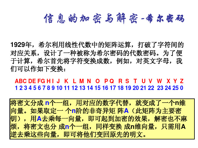
(二)建模案例
1. 2. 3. 4.
赌博问题 信与信封的配对问题 报童的策略 机器任务的分配问题
19
赌博问题
均匀正方体骰子的六个面分别刻有1,2,3,4,5,6 的字样,将一对骰子抛25次决定胜负。问将赌注押 在“至少出现一次双六”或“完全不出现双六”的哪一种 上面有利?
20
问题分析
------骰子是均匀的立方体,所以在一对掷骰子的36种可能结果
如 取 原 整 数 45086273, 可 以 得 到 第 一 个 随 机 数 0.45086273; 将 45086273 右 移 三 位 得 00045086 , 将 45086273 与 00045086按位相加得45021259,将45021259左移四位得 12590000, 将 12590000 与 45021259 按 位 相 加 得 57511259,于是得到第二个随机数0.5751129; 再将 57511259与右移三位的数按位相加得57568760, 将57568760与左移四位的数相加得整数34168760,这就得 到第三个随机数0.34168760。按此规律一直重复下去,可以 得到一个随机数序列。 15
结论 故选取“至少出现一个双六”比较有利。
22
计算机仿真模拟算法
把区间[0,1]等分成6个子区间,使它们与骰子的6六个面一一对应
在[0,1]区间上产生25对均匀分布的随机数x与y 对每对随机数,若它们同时属于第6个子区间,则 认为“出现了双六” 判断25对随机数是否“至少出现了一次双六” 重复上述过程10000次,求“25对随机数中‘至少出 现了一次双六’”的频率,该频率即接近于“至少出现一 次双六”的概率
6
例
取A =
⎡1 ⎢0 ⎣
基于Modelica纯电动汽车用永磁同步电机仿真_陈承鹤

第44卷2011年第11期11月MICROMOTORSVol.44.No.11Nov.2011收稿日期:2011-03-16基金项目:粤港关键领域重点突破资助项目(2007A010301010);广东省国际合作项目(2008A050200008)。
作者简介:陈承鹤(1985),男,硕士研究生,主要研究方向为电动汽车多领域仿真。
熊会元(1973),男,博士,主要研究方向为电动汽车多领域仿真。
基于Modelica 纯电动汽车用永磁同步电机仿真陈承鹤,熊会元,宗志坚,陈业函(中山大学工学院,广州510006)摘要:电动汽车是多领域耦合的复杂物理系统。
基于多领域统一建模语言Modelica 建模,可实现各系统参数无缝求解与优化。
在对电动汽车整车性能仿真分析中,电机驱动系统是电动汽车核心部件,其准确性和实用性占据十分重要位置。
采用Modelica 语言,基于Dymola 平台建立永磁同步电机驱动系统仿真模型,结合电机及驱动系统台架测试实验,对电机驱动系统进行检验和校正。
在此基础上,以实验纯电动汽车整车仿真验证模型,仿真结果与台架测试结果接近,验证了其正确性与可行性。
关键词:电动汽车;永磁同步电机;Modelica ;Dymola 中图分类号:TP391.9;TM341;TM351文献标志码:A文章编号:1001-6848(2011)11-0027-04Simulation of Permanent Magnet Synchronous Motor inElectric Vehicles Based on ModelicaCHEN Chenghe ,XIONG Huiyuan ,ZONG Zhijian ,CHEN Yehan (College of Engineering ,Sun Yat-sen University ,Guangzhou 510006,China )Abstract :Electric vehicles is a complex multi-domain coupled physical system.Based on the multi-domainunified modeling language modelica ,models'parameters of various system can achieve a seamless solution and optimization.In the electric vehicle performance simulation analysis ,electric vehicle motor drive systemis the core components and its accuracy and usefulness occupy a very important position.In this paper ,Mod-elica language was used ,based on Dymola platform ,permanent magnet synchronous motor drive system sim-ulation model was builted and in combination with motor and drive system test bench experiment ,the motordrive system was inspected and corrected.On this basis ,the motor drive system model was tested with an ex-perimental pure electric vehicle simulation ,simulation results close to the results of test bench ,and the cor-rectness and feasibility of this article were verified.Key words :electric vehicle ;PMSM ;Modelica ;Dymola0引言纯电动汽车具有低噪声、零排放、高效及能源多样化等优点,成为各国汽车行业的热点,而电机驱动系统是电动汽车核心部分。
电动汽车电池热管理系统基于模糊控制设计说明书
A Design of Battery Thermal Management SystemBased on Fuzzy ControlZhixiang Xia1, Xiao Ma1, Danfeng Qiu1,*, Gang Bu1, Yongjun Xia1, Bin Zhao2, Zixia Lin2 and Yi Shi21Key Laboratory of Radar Imaging and Microwave Photonics (Nanjing Univ. Aeronaut. Astronaut.), Ministry of Education, College of Electronic and Information Engineering, Nanjing University of Aeronautics and Astronautics, Nanjing, China2National Laboratory of Microstructures and School of Electronic Science and Engineering, Nanjing University, Nanjing, China*Corresponding authorAbstract—Because of the large capacity and high energy density, lithium-ion batteries are often used as power source in electric vehicles. However, in the process of batteries, temperature will significantly adverse the battery, such as shorten the battery life, reduce the battery performance and so on. Therefore, the power battery thermal management system has great influence on the reliable operation of electric vehicles. This paper presents a scheme of battery thermal management system and simulates it through SIMULINK. Simulation results show the effectiveness of the scheme.Keywords—battery thermal management system; electric vehicles; power batteryI.I NTRODUCTIONAs the popularization of automobiles, the problems of environmental pollution and energy shortage caused by traditional diesel locomotive are becoming more and more serious. Therefore, every country in the world is actively and diligently developing electric cars[1-3]. Electric cars are less dependent on fossil fuels than conventional diesel cars, and therefore less polluting.Because of the differences when mass battery production, the erosion of environment, the aging of battery and such irreversible matters, the performance of battery will gradually get worse, even lead to security problems. So battery management system (BMS) is designed as the connection between power battery and electric car, to ensure the safety of power battery[2-5].During the operation of battery, a large amount of heat will be generated, resulting in excessive temperature and uneven distribution of the battery, which will affect the performance and life of the battery. Therefore, it is essential to design a system which can automatically control the temperature of the battery. Such systems are called as battery thermal management system (BTMS), which is an important part of battery management system (BMS)[6-8].In this paper, a battery thermal management system that can make alarm of abnormal battery temperature will be designed, and will be simulated with MATLAB/SIMULINK.II.A D ESIGN OF BATTERY THERMAL M ANAGEMENTS YSTEMThe temperature of battery is nonlinear and time-varying. This kind of system control process is generally complex and the classical control can not achieve satisfactory control effect. Therefore, the fuzzy control method is more suitable for this kind of system. With enough empirical data, a fuzzy mathematical model applicable to fuzzy controller design can be constructed.Human operator's control experience of complex system is summarized into a set of qualitative description of conditional statements, and fuzzy set theory is carried on to quantitatively analyze these statements. This fuzzy controller has the ability to simulate the operation steps of people, just as the replication of human experience[9-10]. Figure I shows the basic structure of fuzzy controller: fuzzification, logic judgment, knowledge base, defuzzification.(1) Fuzzification: change the exact amount of input into the corresponding fuzzy quantity.(2) Logic judgment: simulate the fuzzy concept of person in the process of thinking to obtain the signal of fuzzy control.(3) Knowledge base: provide relevant definitions of fuzzy data and describe control objectives and strategies.(4) Defuzzification: reconvert the inference result into the accurate quantity.E, EC and U are selected as the fuzzy language variables of deviation e, deviation change rate ec and control volume u. Domain is generally set as [-6,6], and the quantification factor Ke, Kc and scale factor Ku can be determined[11-13]. Select a variable-value language E, EC, U: negative big(NB), negative middle (NM), negative small(NS), zero(ZO), positive small(PS), positive middle(PM), positive big(PB) respectively on the theory of domain of fuzzy subset membership functions are triangles. Table I shows the fuzzy control strategy table which is designed according to the manual operation strategy.2018 International Conference on Computer Modeling, Simulation and Algorithm (CMSA 2018)FIGURE I. THE BASIC STRUCTURE OF FUZZY CONTROLLERTABLE I. THE STRATEGY TABLE OF FUZZY CONTROLEU NB NM NS ZO PS PM PBEC NB NB NB NM NM NS NS ZENM NBNM NM NSNS ZEPS NS NM NM NS NS ZE PS PS ZO NM NS NS ZE PS PS PM PS NS NS ZE PS PS PM PM PM NS ZE PS PS PM PM PBPB ZE PS PS PM PM PB PBFigure II shows the battery thermal management system which is related to the fuzzy control theory. The output is detected, and the result is recorded in real time. This research focuses on simulation of the output to determine the condition of the system especially under abnormal temperature. When the input temperature is given, the system can automatically start the adjustment. Temperature data are directly obtained from sensor readings on the battery[14]. Based on the characteristicsof the lithium-ion battery, the temperature must have a maximum value of 40℃ to ensure the safety of the battery.FIGURE II. BATTERY THERMAL MANAGEMENT SYSTEM RELATED TO FUZZY CONTROL THEORYIII. S IMULATION AND A NALYSISTemperature is added as inputs to the battery thermalmanagement system to simulate the heating of the battery. Figure III(a) shows the temperature rise of the battery. It simulates the slow heating of the battery, and at about 100 second, temperature of the battery exceeds the ideal temperature of the lithium battery by 40℃, and then continues to grow slowly. Without the protection of the battery thermal management system, the battery temperature will continue to grow and seriously threaten the safety of the battery. Figure III(b) shows the change of battery temperature in the case of the intervention of battery thermal management system. As canbe seen from the figure, when the battery temperature is greater than 40℃, the battery thermal management system starts and adjusts the temperature automatically. At 120 second, the battery temperature recovered to about 40℃, and has been fluctuating around the temperature since then, demonstrating the effectiveness of the system.(a)(b)FIGURE III.TEMPERATURE OF THE BATTERYIV.C ONCLUSIONAccording to the fuzzy control theory, a reasonable and reliable battery thermal management system is designed, and the system is simulated by MATLAB/SIMULINK. When the battery temperature is higher than the ideal temperature, the system will automatically feed back the data to the cloud, initiate cooling measures, and effectively protect the safety of the battery.A CKNOWLEDGMENTThis work was supported by the National Natural Science Foundation of China (nos 61471195 and 61404087), the Fundamental Research Funds for the Central Universities (NJ20150017 and NS2014040), Aeronautical Science Foundation of China(No. 20152052025).R EFERENCE[1]Pesaran A A. Battery thermal models for hybrid vehicle simulations[J].Journal of Power Sources, 2002, 110(2):377-382.[2]Ge R, Li Y Y. Key Technologies of Thermal Management System forLithium Ion Power Battery[J]. The world of Power Supply, 2017;12:41-47.[3]Zhou Y, Wang Y, Huang C D. Introduction of Battery Pack ThermalManagement System and Its Design Process[J]. Shanghai Auto,2014;06:7-10.[4]Yang G S, Research On Electric Vehicle Battery Thermal ManagementSystem[J]. Science and Technology Innovation Herald, 2015;04:178-180.[5]N. Takami, et al., High-power and long-life Li-ion batteries usinglithium titanium oxide anode for automotive and stationary powerapplications, in:16th International Meeting on Lithium Batteries, ICC Jeju, Korea, 2012.[6]Zhang Y C, Zhu H. Study of electric vehicle battery thermalmanagement system, in: 2011 International Conference on Education Science and Management Engineering, ESME, China, 2011.[7]Lei Z G, Zhang C N. Research development on thermal managementsystem of EVs battery package[J], Chinese Journal of Power Sources, 2011, 12:1609-1612.[8]Tang Z J, Zhu Z Q. Research on thermal management technology forpower batteries[J]. Chinese Journal of Power Sources, 2013, 01:103-106.[9]Wang S Z, Yang S G, Sun G F, Liu Q L. Based on the fuzzy control ofself-tuning fuzzy PID design and simulation, in 2017 Chinese Automation Congress, CAC2017, China, 2017.[10]Dou Y Y, Qian L, Feng J L. Design and Simulation of Fuzzy PIDControl System Based on Matlab[J]. Electronic Science and Technology, 2015, 02:119-122.[11]Zhang E Q, Shi S J, Gao W H, Weng Z X. Recent researches anddevelopment on fuzzy control system[J].Control Theory & Applications, 2001, 02:7-11.[12]Wang H O, Tanaka K., Griffin M.F. An approach to fuzzy control ofnonlinear systems: stability and design issues[J]. IEEE Transactions on Fuzzy Systems, 1996, 02:14-23.[13]Chen J, Xu C F, Wu C S, Xu W H. Adaptive Fuzzy Logic Control ofFuel-Cell-Battery Hybrid Systems for Electric Vehicles[J]. IEEE Transaction on Industrial Informatics, 2018, 01:292-300.[14]Notten P, Bergveld H, Kruijt W. Battery management systems: designby modeling. Boston: Kluwer Academic Publisher; 2002.。
数学模型与数学建模(Mathematical model and mathematical modeling)
数学模型与数学建模(Mathematical model and mathematicalmodeling)Edit reference materials for this competitionCompetition reference bookL, Chinese Undergraduate Mathematical Contest in modeling, edited by Li Daqian, higher education press (1998).2, mathematical modeling contest tutorials, (a) (two) (three), edited by Ye Qixiao, Hunan Education Publishing House (199319971998).3, mathematical modeling education and international mathematics modeling contest "Engineering Mathematics" album, leaves its filial., "Engineering Mathematics" magazine, 1994).Two, domestic teaching materials, books1, mathematical model, Jiang Qiyuan, higher education press (1987 edition, 1993 second edition; the first edition heldin 1992 by the National Education Committee, the second national outstanding teaching award won the "national outstanding teaching award"), mathematical model and computer simulation of.2, Jiang Yuzhao and Xin Pei love series, electronic science and Technology University Press, (1989).3, a mathematical model about selection (to mathematics from the book), Hua Luogeng, Wang Yuan, Wang Ke, Hunan education press; (1991) with the example of.4, mathematical modeling method, Shou Jilin et al, Xi'an Jiao Tong University press (1993),.5 model, Dongpu set country, edited by Tian Yuwen, Southeast University press (1994) the mathematical model of.6.., Zhu Siming, Li Shanglian, Zhongshan University press, 7 (1995), mathematical model,edited by Chen Yihua, Chongqing University press, (1995) 8, mathematical modeling analysis, edited by Cai Changfeng, Science Press,.9 (1995), mathematical modeling contest tutorials, edited by Li Shangzhi, Jiangsu Education Press, (1996).10, mathematical modeling entry, Xu Quanzhi, Yang Jinhao, Chengdu Electronic Science and Technology Press, 11. (1996), mathematical modeling, Shen Jihong, Shi Jiuyu, Gao Zhenbin Zhang Xiaowei, ed., Harbin Engineering University press, 12. (1996), mathematical models, edited by Wang Shuhe, University of Science & Technology China press, 13. (1996), mathematical model method, Jihuan edited, China University of science and Technology Press, (1996).14, mathematical modeling and experiment, Nanjing Engineering College Mathematical Modeling and Industrial Mathematics discussion class, Hohai University press, (1996).15, mathematical model and mathematical modeling, Liu Laifu and Zeng literary series, Beijing Division Fan Du University Press (1997).16. mathematical modeling, Yuan Zhendong, Hong Yuan, Lin Wuzhong, Jiang Lumin, East China NormalUniversity press, 17. Mathematical model, Tan Yongji, Yu Wenpi, Fudan University press, (1997).18, the mathematical model of practical course, Fei Peizhi, Yuan layer process editor, Sichuan University press, (1998).19, mathematical modeling the outstanding cases (Base Construction Engineering Mathematics Series), edited by Wang Guoqiang, South China University of Technology press, (1998).20, economic mathematical model (Second Edition) (construction engineering mathematics base, Hong Yi, He Dehua, Cong Books), edited by Chang Zhihua, South China University of Technology press, (1999).21, the mathematical model of lectures, Gongyan Lei, (Peking University press 1999).22,mathematical modeling cases, edited by Zhu Daoyuan, Southeast University press, (1999), 23, solve the problemof the mathematical model, Liu Laifu, once wrote, theBeijing Normal University press, (1999).24, mathematical modeling theory and practice, Wu Xiang, Ng Man Tat, Cheng Ortega ed., National University of Defense Technology press, (1999).25 analysis, mathematical modeling case, Bai Qi Ling, editor, Ocean Press,.26 (2000, Beijing) (College of mathematics experiment, the selection of teaching materials, Xie Yunsun Zhang Zhirang Series), ed., Science Press,.27 (2000), Fu Peng, Gong Lei, mathematical experiment, Liu Qiongsun, He Zhong, ed., Science Press, (2000).Three. Foreign reference books (Chinese version)1. Introduction to mathematical model, E.A. Bender, Zhu Yaochen, Xu Weixuan, Popular Science Press (1982). 2, the mathematical model, [door] Kondo Jiro, Guan Rong Zhang: Mechanical Industry Press, (1985).3, the differential equation model (model series volume first), beauty editor of]W.F.Lucas, Zhu Yumin et al., National University of Defense Technology press, (1988),.4 (political and related models, the application of mathematical model series Vol. second) [W.F.Lucas, beauty editor, Wang Guoqiu et al., National University of Defense Technology press, (1996).5, and the discrete system model (model series volume third), beauty editor of w.F.Lucas, a Ortega et al., National University of Defense Technology press, (1996) model,.6 (Life Sciences, applied mathematics model in fourth volumes), beauty editor of 1W.F.Lucas, ZhaiXiaoyan et al., National University of Defense Technology press, (1996).7, the mathematical model of continuous dynamical system, and discrete dynamical systems,1H.B.Grif6ths and A.01dknow [English, Xiao Li, Zhijun (compiler, Science Press, 1 996).8, mathematical modeling -- case study from four industries in the United Kingdom, (Applied Mathematics Series No. fourth), theBritish]D.Burglles, Ye Qixiao, Wu Qingbao, World Book Inc, (1997)Four, professional reference books1, the water environment mathematical model,de]W.KinZE1bach, Yang Rujun, Liu Zhaochang, editor, China Architecture Industry Press, (1987) the mathematical model of.2 science and technology engineering, Humphreys Anqi ed., Railway Press (1988), 3 biomedical model, Qingyi science edited by Hunan science and Technology Press (1990) model and application of.4, crop pest management mathematics, Pu Zhelong ed., Guangdong science and Technology Press (1990),.5 in system science and mathematics model, editedby Ouyang Liang E, Shandong University press, (1995) the mathematical modeling and research of.6, population ecology, Ma Temple, Anhui Education Press, 7, (1996), modeling new progress in the transformation, optimization, comprehensive method, structure of Sui Yunkang, Dalian University of Technology press, 8, (1986) the genetic model analysis method, Zhu Jun, agriculture press China (1 997). (editedby Wang Shousong, Department of mathematics, Zhongshan University, April 2001)Editing the format requirements of this paragraphA team from A,B in the optional one, group B teams from C, D choose a topic. The white A4 paper printed on one side;on each side set aside at least 2.5 cm from the left margin; binding. The first page of the paper is a commitment, and the specific content and format are shown in the secondpage of this specification. The second page number for the special page, front and back for the regional and national review of the paper number, specific content and format see page third of this specification. The title and abstract of the paper are written on the third page of the paper, starting from the fourth page, and the main body of the paper. The paper starts with third pages, the page number must be located in the middle of each page footer, with Arabia number from "1" start serial number. There is no header in the paper, and there is no sign in the paper that can show the identity of the person who answers the question. The title of this paper is "three" boldface, and the first title is in boldface No. four, and centered. This paper adopts four other Chinese characters Song typeface, with single spaced pages, print should be avoided in color printing. Abstract: draw attention should be a detailed summary of the concise and to the point (including keywords), occupies an important weight in the whole paper review, please carefully write (note the length of no more than one page, and there is no need to be translated into English). The review will first according to the quality of the paper and the overall structure of the thesis and overview of the preliminary screening. The quotation ofother's achievements or other public information (includingthe data found on the Internet) must be clearly listed in the references and references in accordance with the provisions of the reference. The reference in the text uses square brackets to mark the reference number, such as[1][3], etc., and the book must also point out the page number. The references are listed in the quotation order of the text, in which the book is expressed as: author, title, publication place, publishing house, publishing year. The methods of expression of journal articles in reference books are: author, paper name, Journal name,Volume number, page number, year of publication. The reference resources in the literature are: author, resource title, URL, access time (month, date). In the premise of not breaking the regulations, each division can increase the other requirements (such as adding other pages and other information on the first page of this specification before or at the end of this paper add blank page etc.); from the beginning to the end of the undertaking, the division shall not have any other requirements of this specification the (or null). The right of interpretation belongs to the Organizing Committee of the National Mathematical Contest for modeling students. [note] division marking the papers before the first page take preservation, and to establish "division marking numbers in the first and second pages" (by the way, "the provisions of division number) division table can be used for marking the record review (division each division to decide whether to use the form in review). After review, the division sent to the national review papers to establish a national unified numbering in the second page "(numbering by the organizingcommittee, and last year the same format), and then sent to the national review. The second page (page number) preserved by the National Organizing Committee review before take off, and the establishment of the national review number on page second". The National College Mathematical Contest in modeling was revised in September 12, 2008Edit the competition GuideWhat is mathematical model and mathematical modeling?Simply put: mathematical models are a mathematical expression of practical problems. Specifically, the mathematical model is an abstract, simplified mathematical structure of some real world for some purpose. Rather, the mathematical model is for a specific object to a specific target, according to the unique inherent laws, make some simplifying assumptions necessary, using appropriate mathematical tools, a mathematical structure is obtained. Mathematical structures can be mathematical formulas, algorithms, tables, diagrams, etc.. Mathematical modeling is the establishment of mathematical models, the process of establishing mathematical models is the process of mathematical modeling (see mathematical modeling process flow chart). Mathematical modeling is a mathematical thinking method, is the use of mathematical language and methods, through the abstract and simplify the establishment of an approximate description and "solve" practical problems of a powerful mathematical means.First, the mechanism analysis method: the model is deduced from the basic physical law and the structural data of the system. 1. scale analysis -- the most basic and most commonly used method to establish the functional relationship among variables. 2. algebraic method -- the main method for solving discrete problems (discrete data, symbols and graphs). 3. logic method is an important method of mathematical theory research. It is widely used in the fields of sociology and economics, in decision-making, countermeasures and other disciplines. 4. ordinary differential equation - to solve the law of variation between two variables, the key is to establish the expression of "instantaneous rate of change". 5. partial differential equation -- solving the law of variation between dependent variable and more than two independent variables. Two. Data analysis method establishes mathematical model by using statistical method from a large number of observation data. 1. regression analysis - a set of observations (Xi, FI) i=1,2 for function f (x)... N, which determines the expression of a function, is called a mathematical statistical method because it is a static independent data. 2. time series analysis deals with dynamic related data, also known as process statistics. 3. regression analysis - a set of observations (Xi, FI) i=1,2 for function f (x)... N, which determines the expression of a function, is called a mathematical statistical method because it is a static independent data. 4. time series analysis deals with dynamic related data, also known as process statistics. Three, simulation and other methods 1. computer simulation (simulation) - essentially statistical estimation method, equivalent to the sampling test.Discrete system simulation - there is a set of state variables. Continuous system simulation with analytic expression or system structure diagram. 2. factor test method -- local test on the system, then according to the test results for continuous analysis and modification,The required model structure is obtained. 3. artificial reality method, based on the understanding of the past behavior of the system and the desired future goals, and taking into account the possible changes in the relevant factors of the system, artificially forming a system. (see: Qi Huan, mathematical modeling method, Huazhong University of science and Technology Press, 1996)IV. types of questionsMatch questions structure has the following parts: background, problems involving wide 1. - social, economic, management, life, environment, natural phenomena, engineering technology, modern science in the new issue. 2. generally, there is a definite practical problem. Two, some assumptions are as follows: 1. only the process and rules of qualitative assumptions, no specific quantitative data;2. are some survey or statistics;3. gives a number of parameters or graphics;4. contains some assumptions of mobility, can play, or players can according to their own collection or simulated data. Three, asked to answer the question often have several problems (generally not only answer: 1.) more definitive answers (basic answers); 2. more detailed or high-level discussion results (often is the optimal scheme formulation and results).Competition answer paperTo submit a paper, the basic content and format is roughly divided into three parts: first, the title, abstract part:1. topics - write a more precise topic (not only write A,B). 2. Abstract --200-300 words, including the main features of the model, modeling methods and main results.3., when there is more content, it is better to have a directory. Two, the central part: 1. problem raised, problem analysis. 2. models: the complementary hypothesis, clear concept, the introduction of the model parameters; form (with multiple models); for the model; the model of nature; the realization of computer design and calculation method of the 3.4. result analysis and test.5. discuss the advantages and disadvantages of the model, improve the direction, and promote new ideas.6. references -- attention format. Three. Appendix: 1. calculation program, block diagram. 2. solving the calculus and calculating the intermediate result. 3. various graphics and forms.Edit this paragraph competition questions collection1992 (A) fertilizer effect analysis problem (Ye Qixiao: Beijing Institute of Technology) (B) experimental data decomposition (East China University of Science and Technology: Yu Wen; Fudan University: Tan Yongji) 1993 (A) frequency design problem of nonlinear intermodulation (Peking University: Xie Zhongjie) (B) football ranking problem (Tsinghua University: Cai Dayong) 1994 (A) of cut paths through mountains (He Dake: Xi'an Electronic andScience University) (B) the problem of packing locks (Fudan University: Tan Yongji, East China University of Scienceand Technology: Yu Wenci) 1995 (A) flight management problems (Fudan University: Tan Yongji, East ChinaUniversity of Science and Technology: Yu Wenci) (B) scheduling problem of crane and smelting furnace (Zhejiang University: Liu Xiangguan, Li Ji Luan) 1996 (A) the problem of optimal fishing strategy (Beijing Normal University: Liu Laifu) (B) of water-saving washing machine ask Question (Chongqing University: Fu Li) in 1997 (A) design parameters of parts (Tsinghua University: Jiang Qiyuan) (B) cutoff problem (Fudan University: Tan Yongji,East China University of Science and Technology: Yu Wenci) 1998 (A) risk and return of investment (Chen Shuping: Zhejiang University) (B) routing problem (disaster tour of Shanghai Maritime University: Ding Songkang) 1999 (A) automatic lathe management problems (Peking University: Sun Shanze) (B) drilling layout problem (Zhengzhou University: Lin Yixun) (C) of coal accumulation gangue (Taiyuan University of Technology: Jia Xiaofeng) (D) drilling layout (Zhengzhou University: Lin Yixun) 2000 (A) DNA sequence classification (Meng Dazhi: Beijing University of Technology) (B) order and transportation of steel tubes (Wuhan University: Fei Fusheng) (C) over the Arctic problem (Fudan University: Tan Yongji) (D) (Northeast Dianli University: the problem of detecting cavity the letter of 2001) (A) 3D reconstruction of vessels (Zhejiang University, Wang Guozhao) (B) bus scheduling problem (Tsinghua University: Tan Zeguang) (C) the problem of using funds (Southeast University: Chen Enshui) (D) bus schedulingproblem (Tsinghua University: Tan Zeguang) 2002 (A) the optimization problem of the headlight design (Tan Yongji: Fudan University, East China University of Science and Technology: Yu Wenci) (B) (mathematical problems in lottery The PLA Information Engineering University: Han g) (C) the optimization problem of the headlight design (Tan Yongji: Fudan University, East China University of Science and Technology: Yu Wen) (D) schedule problem (Tsinghua University: Jiang Qiyuan) 2003 (A) spread SARS (LOC) (B) vehicle scheduling problems in open-pit mine production (the Jilin University: Peichen (party) the problem of SARS (C) communication committee) (D) crossing Yangtze River (Huazhong Agricultural University: Yin Jiansu) 2004 (A) Temporary Supermarket Design Problems (Beijing University of Technology: Meng Dazhi) (B) power transmission congestion management (Zhejiang University: Liu Kangsheng) (C) drunk driving problem (Tsinghua University: Jiang Qiyuan) (D) recruitment problem (The PLA Information Engineering University: Han Zhonggeng) 2005 (A) evaluation of water quality of Yangtze River and prediction problem (Han Zhonggeng: The PLA Information Engineering University) (B) DVD online leasing problem (Tsinghua University: Xie Venus) (C) evaluation of rainfall forecast methods (Tan Yongji: Fudan University) (D) DVD online leasing problem (Tsinghua University: Xie Venus, 2006) (A) (Beijing University of Technology press the issue of resource allocation: Meng Dazhi) (B) the prediction problem of AIDS therapy evaluation and the effect of (Tianjin University: Fu Ping) (C) to optimize the cans The problem of designing (Beijing Institute of Technology: Ye Qixiao) (D) monitoring and control of coal mine gas and coal dust (The PLAInformation Engineering University: Han Zhonggeng) 2007 (A) China population growth forecast (B) bus, look at the Olympic Games (C) mobile phone packages preferential geometric (D) body test schedule in 2008 (A) digital camera positioning (B), the standard of higher education tuition, ground search (C), (D) analysis and evaluation of the NBA Calendar 2009 (A) control method of the brake test rig (B) reasonable arrangement for ophthalmic beds (C) satellites and spacecraft tracking control (D) Conference 2010 (A) storage tank the identification and calibration of tank capacity table (B) quantitative assessment of World Expo's influence in Shanghai in 2010 (C) pipeline layout (D) for students The evaluation of dormitory design: C, D is the junior college group competitionEdit this paragraph competition significance1, cultivate innovative consciousness and creative ability of rapid access to information and data of 2, 3, exercise training to quickly understand and master new knowledge and skills training 4, teamwork and team spirit 5, enhance writing skills and typesetting technology of 6, won the National Award for Paul sent 7 graduate students, won the international level the reward is beneficial to apply for studying abroad 8, more important is the training oflogical thinking and open way of thinkingThe social application of editing the mathematical modeling contestThe application of mathematical modeling is a great impetusand impetus for the contest of mathematical modeling. At present, the first domestic mathematical modeling company - Beijing Noah Mathematical Modeling Technology Co., Ltd. was established in Beijing. Wei Yongsheng, a doctoral student, worked with two other like-minded students in the field of entrepreneurial modeling, from the domain of mathematical modeling that they were familiar with. Wei Yongsheng three people set up a mathematical modeling contest team in April 2003, then won the two prize of state, in 2005 won thefirst prize in the international contest of mathematical modeling, the same year in October registered the mathematical modeling in mathematical modeling enthusiasts website, to society, to the direction of the application, they formally established in June last year to the application mathematical modeling for entrepreneurial direction, the formation of entrepreneurial team, opened the road of entrepreneurship. Earlier this month, Beijing's mathematical modeling technology limited company officially registered, Wei Yongsheng entrepreneurial team officially on track. At present, Noah mathematical modeling is its specialization from the perspective of business to expand its strength, mathematical modeling and mathematical model and actively involved in the railway transportation, highway transportation, logistics management and other related solutions and consulting services. Wei Yongsheng explained to reporters, maybe a lot of people do not understand what is the use of mathematical modeling, he cited an example of a train station, to calculate how long a car can not only ensure the passengers were taken away, and to the greatest degree of cost savings, the mathematical model can be calculated by the optimal scheme.Wei Yongsheng said that their mathematical modeling team has been 6 years of history, with each other, very tacit understanding, but also made dozens of large and small projects. Their business philosophy is to provide a hitherto unknown mathematical modeling and mathematical model of optimal solutions for the direct and potential customers, minimize production cost, realize investment income for the customers. More Atlas。
数学模型MathematicalModeling精品文档39页

例2 某人第一天由 A地去B地,第二天由 B地沿原路返回 A 地。问:在什么条件下, 可以保证途中至少存在一地,此人在两天 中的同一时间到达该地。
分析 本题多少 有点象 数学中 解的存在 性条件 及证明,当 然 ,这里的情况要简单得多。
Requirements(1)
模型报告书写
符合规范 文字,图表清晰 数据说明
Requirement(3)
独立完成 相互帮助 团队合作 绝不允许抄袭!
Q&A
一些简单实例
§1.5 一些简单实例
•例1 某人平时下班总是按预定时间到达某处,然 然后他妻子开车接他回家。有一天,他比平时提早 了三十分钟到达该处,于是此人就沿着妻子来接他 的方向步行回去并在途中遇到了妻子,这一天,他 比间平?请时思提考前一了下十,解载天十会 段 开 达 五分本合路5会分了 着 他 分分钟点的合钟题换 显。 他 就 钟钟,缘点。然到一假 开 不 时。解又故,是种如 往 会 间而似家从,故答由想此他 会 提 从乎会故相于,人法的 合 前 何中合由遇节条提,妻 地 回 而问点相时省隐前件问子 点 家 来返遇他了此了含不回点已题遇 , 了 ?从三相到步人就到 那 。相够了十遇会行遇迎他 么 提分哦共哪点合了点刃后 这 前钟这点二步到。仍 一 的而些到一需十。行假了设多长?时
第一章 建立数学模型
开设本课程的目的: 引起注意、激发兴趣、介绍方法、 培养能力
数学?
数学有没有用?
数学不是没有用,而是不够用 现有的数学工具不能解决所有实际问题
怎么用?
解决实际问题 数学模型 ☺
数学模型与数学建模
➢ 数学模型(Mathematical Model)
是用数学符号、数学式子、程序、图形等对实际课题 本质属性的抽象而又简洁的刻划,它或 能解释某些客观 现象,或能预测未来的发展规律,或能为控制某一现象 的发展提供某种意义下的最优策略或较好策略。
mathematical modeling

说明:任何改变铺设方式的努力都是徒劳
棋子颜色的变化
任意拿出黑白两种颜色的棋子共八个,排成一个圆圈. 然后在两颗颜色相同的棋子中间放一颗黑色棋子,在两 颗颜色不同的棋子中间放一颗白色棋子,放完后撤掉原 来所放的棋子.再重复以上的过程,这样放下一圈后就拿 走前次的一圈棋子,问这样重复进行下去各棋子的颜色 会怎样变化呢?
仍设扣除反应时间后为t= 3.9秒,代入式(1)求得
h≈69.9(米)
则回声传回时间为
t2 =h/340 ≈0.21(秒)
故 求得
t1 =t-t2 ≈3.69 h≈62.3 (米)
动物体重的变化问题
某动物从食物中每天得到2500卡的热量,其中 1200卡用于基本的新陈代谢,每天每公斤的体重 需要再消耗16卡。假如它每增加1公斤体重需要 10000卡的热量。问该动物的体重怎样变化?
d 2h dh m 2 = mg − r dt dt dh 令k→ 0 + ,即可得出前面 h(0) = 0, | t = 0 = 0 dt 不考虑空气阻力时的结果
令k=r/m,解得
g g − kt g h(t ) = t + 2 e − 2 k k k
(1)
若设k=0.05,并仍设 t=4秒,则可求得h ≈米。
我有一只具有跑 表功能的计算器。
简单想法
记崖高为h 假定空气阻力不计,可以利用自由落体运动的公式来计 算。
1 h = gt 2
2
例如, 设测得时间为t=4秒,
g=9.81米/秒2,则可求得
h ≈78.5 (米)
我学过微积分,我可以做 得更好,呵呵。
进一步考虑
除去地球吸引力外,对石块下落影响最大的当属空气 阻力。根据力学知识,此时可设空气阻力正比于石块下落 的速度,阻力系数 r 为常数。 由牛顿第二定律可得:
基于wltc工况的电动汽车能量流测试与分析

【摘要】为研究电动汽车的能量流,首先对比了WLTC 工况与NEDC 工况,证明了WLTC 工况更能反映整车行驶过程中的能耗特性,然后基于WLTC 工况,依据电能部分的能量流测试方案,综合考虑车辆行驶过程中机械能、电能的流动方向和大小,建立纯电动汽车行驶过程中的能量流数学模型,最后,根据模型中各系统或零部件输入与输出的瞬时值与累计值计算其能量传递效率,从而从整车级、系统级、零部件级全面评价测试车辆能耗特性。
主题词:NEDC 工况WLTC 工况能量流测试数学模型中图分类号:U469.72文献标识码:ADOI:10.19620/ki.1000-3703.20181071Energy Flow Test and Analysis of Electric Vehicle Based on WLTCModeZhang Wei 1,Xu Jinbo 2,3,Wang Xu 2,Yang Tian 2(1.The Development Center of Equipment Industry of Ministry of Industry and Information Technology,Beijing 100846;2.China Automotive Technology Research Center Co.,Ltd.,Tianjin 300300;3.Chang ’an University,Xi ’an 710064)【Abstract 】To study the energy flow of electric vehicle,this paper firstly compares the WLTC cycle with the NEDCcycle,and proves that the WLTC cycle can reflect the energy consumption characteristics of the vehicle in driving betterthan the NEDC cycle.Then,the energy flow mathematical model of battery electric vehicle is established based on WLTC cycle and according to energy flow test plan of electric power,comprehensively considering flow direction and size of mechanical energy and electric power of vehicle in driving.Finally the energy transfer efficiency is calculated according tothe instantaneous value and cumulative value of input and output of each system or component in the energy flow mathematical model,thus the energy consumption characteristics from the vehicle level,system level and component level are evaluated and tested.Key words:NEDC cycle,WLTC cycle,Energy flow test,Mathematical model张微1徐金波2,3王旭2杨天2(1.工业和信息化部装备工业发展中心,北京100846;2.中国汽车技术研究中心有限公司,天津300300;3.长安大学,西安710064)基于WLTC 工况的电动汽车能量流测试与分析汽车技术·Automobile Technology1前言纯电动汽车续驶里程是制约其发展的重要因素之一,动力电池是纯电动汽车唯一的动力源,其能量利用效率直接影响整车的续驶里程。
foc 开环强拖原理
foc 开环强拖原理The problem at hand is to understand and explain the principle of "foc (field-oriented control) open-loop strong dragging" in the context of electric motor control. This principle is commonly used in the field of robotics, automation, and electric vehicles to achieve precise and efficient control of electric motors. In order to meet the requirements of this task, I will provide a comprehensive explanation in multiple paragraphs from different perspectives.From a technical perspective, foc open-loop strong dragging refers to a control strategy that aims to achieve high torque and speed control accuracy in electric motors. It involves controlling the stator current of the motor to align with the rotor magnetic field, which results in improved motor performance. By using a mathematical model of the motor and its control algorithms, the control system can accurately predict and adjust the stator current to achieve the desired torque and speed response. This controlstrategy is particularly effective in applications where high torque and precise control are required, such as industrial robotics and electric vehicles.From a practical standpoint, foc open-loop strong dragging offers several advantages over other control strategies. Firstly, it provides high torque density, meaning that it can deliver a high level of torque output relative to the motor size. This is crucial in applications where space is limited, such as in compact robots or electric vehicles. Secondly, it enables precise control of motor speed and torque, allowing for smooth and accurate motion control. This is particularly important in tasksthat require precise positioning or high-speed operation. Additionally, foc open-loop strong dragging is known forits efficiency, as it minimizes energy losses and heat generation in the motor, resulting in improved overall system efficiency and longer operational life.From a user's perspective, the principle of foc open-loop strong dragging translates into improved performance and reliability of electric motor-driven systems. Forexample, in an industrial robot, the precise control of motor torque and speed provided by this principle allowsfor smooth and accurate movement, enabling the robot to perform complex tasks with high precision. Similarly, in an electric vehicle, the high torque density and efficient control offered by foc open-loop strong dragging contribute to improved acceleration, range, and overall driving experience. These benefits enhance user satisfaction and enable the development of advanced applications that rely on electric motor control.From a societal perspective, the principle of foc open-loop strong dragging aligns with the global trend towards clean and sustainable energy solutions. Electric motors are widely used in various industries, and by improving their performance and efficiency, we can reduce our dependence on fossil fuels and decrease harmful emissions. The precise control provided by foc open-loop strong dragging also enables the development of more sophisticated and autonomous systems, such as self-driving cars or advanced industrial automation, which can contribute to increased productivity and safety. Moreover, the widespread adoptionof this principle can drive technological advancements and create new job opportunities in the field of electric motor control and related industries.In conclusion, the principle of foc open-loop strong dragging is a control strategy that aims to achieve high torque and speed control accuracy in electric motors. It offers advantages such as high torque density, precise control, and improved efficiency. From a user's perspective, it translates into improved performance and reliability in electric motor-driven systems. From a societal perspective, it aligns with the global trend towards clean energy solutions and can drive technological advancements. By understanding and utilizing this principle, we can unlock the full potential of electric motor control and contribute to a more sustainable and advanced future.。
驻车制动参考文献
驻车制动参考文献驻车制动是汽车安全性能中非常重要的一部分,它的目的是在汽车停放过程中确保车辆停稳,防止车辆滑动或者移动。
驻车制动通常由制动器、缓速器以及相关控制系统组成。
为了确保驻车制动系统正常工作,需要进行充分的研究和测试。
在文献中有很多关于驻车制动的相关研究和测试的参考内容。
以下是一些重要的参考内容:1. Tony, Q.et.al. (2012). "A Study on the Performance of Parking Brake Control for Electric Parking Brake (EPB)". International Journal of Automotive Technology. 13(1), pp. 71-78.这篇论文主要研究了电子驻车制动(EPB)系统的性能。
通过实验和测试,作者评估了EPB的刹车动态特性和制动性能。
研究结果表明,EPB系统能够提供更好的刹车控制和稳定性。
2. Radik, A.et.al. (2015). "Analysis of parking brake pads wear rate". Archives of Transport. 36(1), pp. 111-120.这篇研究主要分析了驻车制动刹车片的磨损情况。
作者通过实验测试,评估了刹车片的磨损速率和影响因素。
结果表明,驻车制动刹车片的磨损速率与使用条件和材料特性密切相关。
3. Célio, Z.et.al. (2018). "Development of a Mathematical Modelfor Assessment of the Roller Brake Tester Used in Vehicle Safety Inspections". SAE International Journal of Vehicle Dynamics, Stability, and NVH. 2(1), pp. 9-18.这篇论文开发了一个数学模型,用于评估驻车制动系统的滚筒式刹车测试机。