GB160160BNYBBMDB-V00中文资料
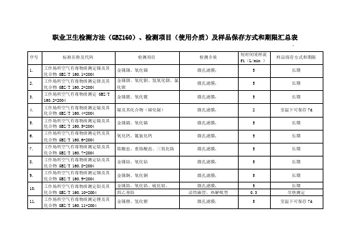
职业卫生检测方法GBZ160检测项目使用介质及样品保存方式和期限汇总表
微孔滤膜,
5
长期
24.
工作场所空气有毒物质测定钒及其 化合物GBZ/T 160.24-2004
钒铁合金、五氧化二钒
微孔滤膜,
5
长期
25.
工作场所空气有毒物质测定锌及其 化合物GBZ/T 160.25-2004
金属锌、氧化锌、氯化锌
微孔滤膜,
5
长期
26.
工作场所空气有毒物质测定锆及其
化合物GBZ/T 160.26-2004
微孔滤膜,
5
长期
3.
工作场所空气有毒物质测定GBZ/T 160.2-2004
金属镀、氧化镀
微孔滤膜,
5
长期
4.
工作场所空气有毒物质测定铋及其 化合物GBZ/T 160.4-2004
铋及其化合物(碲化铋)
微孔滤膜,
2
室温下可保存7d
5.
工作场所空气有毒物质测定镉及其 化合物GBZ/T 160.5-2004
金属镉、氧化镉
微孔滤膜,
5
长期
6.
工作场所空气有毒物质测定钙及其
化合物GBZ/T 160.6-2004
氧化钙、氰氨化钙
微孔滤膜,
5
长期
7.
工作场所空气有毒物质测定铭及其 化合物GBZ/T 160.7-2004
铭酸盐、重铬酸盐、三氧化铬
微孔滤膜,
5
长期
8.
工作场所空气有毒物质测定钻及其 化合物GBZ/T 160.8-2004
苯、甲苯、二甲苯、乙苯、苯乙 烯
活性炭管,溶剂解吸型
0.1
冰箱内至少可保存14d
活性炭管,热解吸型
对-特丁基甲苯
活性炭管,溶剂解吸型
GBZ160现场采样参数及方法汇总表

一氧化碳
GBZ/T 160.28-2004无机含碳化合物
-
20
30
-
注射器,100ml,2ml
在采样点,用空气样品抽洗100ml注射器3次,然后抽取100ml空气样品。
立即封闭进气口后,垂直放置,置清洁容器内运输和保存,尽快测定。
二氧化碳
同上
非高原
-
9000
18000
-
铝塑采气袋,0.5-1L
2.
镉及其化合物
GBZ/T 160.5-2004
镉及其化合物
-
0.01
0.02
G1
同上
同上
同上
3.
钙及其化合物
GBZ/T 160.6-2004
镉及其化合物
-
2
-
-
同上
同上
同上
4.
铬及其化合物
GBZ/T 160.07-2004铬及其化合物
-
0.05
-
G1
同上
同上
同上
5.
铜及其化合物
GBZ/T 160.09-2004铜及其化合物
现场采样参数及方法汇总表
序号
名称
检测标准(方法)名称及编号(含年号)
MAC
PC-TWA
PC-STEL
备注
采样器
采样方法
样品保存
1.
钡及其化合物
GBZ/T 160.2-2004
钡及其化合物
-
0.5
1.5
-
微孔滤膜,孔径0.8μm
采样夹,滤料直径40mm
小型塑料采样夹,滤料直径25mm
空气采样器,流量0-3L/mi和0-10L/min
在采样点,用一直装有5.0ml吸收液的多孔玻板吸收管,置于冰浴内,以0.5L/min流量采集15min空气样品。
GB160160BNYABMDB-V00中文资料
JEWEL HILL ELECTRONIC CO.,LTDJEWEL HILL ELECTRONIC CO.,LTD.SPECIFICATIONS FORLCD MODULEModule No. GB160160BOffice Address: Rm. 518,5/F., 101 Shangbu Industrial District,HuaqiangNorthRoad, Shenzhen, ChinaTEL : (86)-755-83362489 83617492FAX: (86)-755-83286396 83365871E-mail: sales@jhlcd@Website: TABLE OF CONTENTSLCM NUMBER SYSTEM (2)1. GENERAL DESCRIPTION (3)2. FEATURES (3)3. MECHANICAL SPECIFICATION (3)4. MECHANICAL DIMENSION (4)5. MAXIMUM RATINGS (5)6. ELECTRICAL CHARACTERISTICS (5)7. MODULE FUNCTION DESCRIPTION (6)8. ELECTRO-OPTICAL CHARACTERISTICS (13)9. RELIABILITY (17)10. PRECAUTIONS FOR USING LCD MODULES (18)11. USING LCD MODULES (20)12. REVISION HISTORY (22)SAMPLE APPROVED REPORT (23)LCM Number SystemNUMBER OF CHAR. PER LINE F: FSTN; X: OTHER VERSION NUMBER: V00~V99IC TYPE:VIEWING DIRECTION:TEMPERATURE RANGE:BACKLIGHT TYPE:SERIAL NUMBER: A~ZGRAPHIC MODULEs: NUMBER OF COMMONs GRAPHIC MODULEs:NUMBER OF SEGMENTs COB & SMT LCM BACKLIGHT COLOR:CHARACTER MODULEs:CHARACTER MODULEs: NUMBER OF LINE G: REFLECTIVE,NONE BACKLIGHT A: TRANSFLECTIVE, EL BACKLIGHT B: TRANSMISSIVE, EL BACKLIGHT C: TRANSFLECTIVE, LED BACKLIGHT D: TRANSMISSIVE, LED BACKLIGHT E: TRANSFLECTIVE, CCFL BACKLIGHT F: TRANSMISSIVE, CCFL BACKLIGHT A: AMBER; B: BLUE; Y: YELLOW-GREEN R: RED; W: WHITE; O: THER COLOR N: NORMAL TEMPERATURE RANGE U: UPPER(12:00); D: DOWN(6:00)L: LEFT(9:00); R: RIGHT(3:00);A: BONDING IC, WITH CONTROLLER B: BONDING IC, WITHOUT CONTROLLER C: SMT IC, WITH CONTROLLER D: SMT IC, WITHOUT CONTROLLER O: OTHER TYPEW: BLACK-WHITE; O: OTHER G: GRAY; Y: YELLOW-GREEN; B: BLUE; LCD COLOR MODE:N: TN; H: HTN; S: STN LCD TYPE:S: SUPER WIDE TEMPERATURE RANGE W: WIDE TEMPERATURE RANGEM: MIDDLE TEMPERATURE RANGE1. GENERAL DESCRIPTIONThe GB160160B is a 160 x 160 Dots Graphics LCD module. It has a STN panel composed of160segments and 160 commons. The LCM can be easily accessed by micro-controller via parallel interface.2. FEATURESTransflective and PositiveDisplay ModeSTN(Y-G) moduleDisplay Format Graphic 160 x 160 dotsInput Data Parallel data input from MCUMultiplexing Ratio 1/160 DutyBiasBias 1/12Viewing Direction 6 O’clock(Yellow-Green)Backlight LED3. MECHANICAL SPECIFICATIONItem Specifications Unit Dimensional outline 89.2 x 85.0 x 14.6(max) mmResolution 160segs x 160coms dotsActive area 60.775(W) x 60.775(H) mmDots pitch 0.38(W)×0.38(H) mmDots size 0.355(W)×0.355 (H) mm4. MECHANICAL DIMENSION5. MAXIMUM RATINGSItem Symbol Min Max Unit NoteV DD - V ss -0.3 5.5 V Supply voltage V LCD -0.3 24.0 V Input Voltage V IN -0.3 V DD +0.3 VOperating temperature T OPR 0 +50 Storage temperature T STR -10 +60Humidity --- --- 90 %RH6. ELECTRICAL CHARACTERISTICSItem SymbolCondition Min. Typ. Max. UnitSupply Voltage Logic V DD ------ 5.0 --- VH level V IH 0.8V DD --- V DDInput VoltageL levelV IL --- V SS --- 0.2V DDVCurrent Consumption(LCD DRIVER)I DD V DD =5.0V; V LCD =19.0V, T amb =25 ;--- --- 1.5 mALCD Driving Voltage V LCDBias=1/13V LCD =V DD -V 518.7 19.0 19.3 VCurrent Consumption (With LED BackLight)I LEDV DD =5.0V;V LED =4.2V,T amb =25 ;--- --- TBD mA7. MODULE FUNCTION DESCRIPTION7.1. PIN DESCRIPTIONINTERFACE WITH CN1 & CN2:PinSymbol Description No.1 VSSPower supply for Ground (0V)2 MAC Signal for LCD Driver Output3 FLMData Input for Common ICs4 CL1Data Latch Colok5 CL2Data Shift Colok6 D37 D2Display Data Input Terminal for Segment ICs8 D19 D010 VEE Power Supply for Negative V oltage11 VDD Power supply for positive (+5V)12 V0 VLCD V oltage Regulation Terminal13 /DISPOFF Display OFF Control14 K Power Supply for LED BackLight Negative15 A Power Supply for LED BackLight Positive7.2 TIMING CHARACTERISTICS7.3 APPLICATION OF LCMLED-LED+VDD VSS VEE V0D0-D4CL1CL2M FLMCircuit Block Diagram8. ELECTRO-OPTICAL CHARACTERISTICSItem Symbol Condition Temp Min Typ. Max UnitsNote--- 19.5 ---25 18.7 19.0 19.3 LCD driving voltageV LCD = = 050 --- 18.0 --- V NOTE1Rise Time (Tr) --- --- -- Decay Time (Tf)0 --- ---- --- Rise Time (Tr) --- 225 340Decay Time (Tf) 25 --- 240 360Rise Time (Tr) --- --- -- Response TimeDecay Time (Tf)= = 0 50 --- --- --msec NOTE2Contrast Ratio Cr= = 0 255 10 --- --- NOTE4Viewing AngleRange( = 0°)(6”) = 90°(3”) =180°(12”) =270°(9”)(25 ) CR ≥245 35 25 35DegNOTE3z For panel only․Electro-Optical Characteristics Measuring Equipment(DMS501)SystemIllumination (D65)․Note 1. Definition of Driving Voltage( Vlcd) :․Note 3. Definition of Viewing Angle and :․Note 4. Definition of Contrast ratio( CR) :Brightness of Non-selected Segment (B2)Brightness of Selected Segment (B1)CR =V,maxCR,maxDriving VoltageB r i gh t n e s s (%)Brightness Curve forSelected Segment0%=90 =270Viewing Direction 6 O’clock DirectionNormal :9. RELIABILITY9.1. MTBFThe LCD module shall be designed to meet a minimum MTBF value of 50000 hours with normal. (25°C in the room without sunlight)9.2. TESTSNO. ITEM CONDITION CRITERION 1 High Temperature Operating 50 120Hrs2 Low Temperature Operating 0 120Hrs3 High Temperature/Humidity Non-Operating50 ,90%RH ,120 Hrs4 High TemperatureNon-Operating60 120Hrs5 Low TemperatureNon-Operating-10 120Hrs6 Temperature CyclingNon-Operating 0 (30Min )↔ 50 (30Min)10 CYCLESNo Defect OfOperational Function InRoom Temperature AreAllowable.IDD of LCM inPre-and post-test shouldfollow specificationNotes: Judgments should be mode after exposure in room temperature for two hours.10. PRECAUTIONS FOR USING LCD MODULES10.1. HANDLING PRECAUTIONS(1) The display panel is made of glass. Do not subject it to a mechanical shock or impact by droppingit.(2) If the display panel is damaged and the liquid crystal substance leaks out, be sure not to get any inyour mouth. If the substance contacts your skin or clothes, wash it off using soap and water.(3) Do not apply excessive force to the display surface or the adjoining areas since this may cause thecolor tone to vary.(4) The polarizer covering the display surface of the LCD module is soft and easily scratched. Handlethis polarizer carefully.(5) If the display surface becomes contaminated, breathe on the surface and gently wipe it with a softdry cloth. If it is heavily contaminated, moisten a cloth with one of the following solvents: - Isopropyl alcohol- Ethyl alcohol(6) Solvents other than those above mentioned may damage the polarizer.Especially, do not use the following:- Water- Ketone- Aromatic solvents(7) Extra care to minimize corrosion of the electrode. Water droplets, moisture condensation or acurrent flow in a high-humidity environment accelerates corrosion of the electrode.(8) Install the LCD Module by using the mounting holes. When mounting the LCD Module, makesure it is free of twisting, warping and distortion. In particular, do not forcibly pull or bend the I/Ocable or the backlight cable.(9) Do not attempt to disassemble or process the LCD Module.(10) NC terminal should be open. Do not connect anything.(11) If the logic circuit power is off, do not apply the input signals.(12) To prevent destruction of the elements by static electricity, be careful to maintain an optimumwork environment.- Be sure to ground the body when handling he LCD Module.- Tools required for assembling, such as soldering irons, must be properly grounded.-To reduce the amount of static electricity generated, do not conduct assembling and other workunder dry conditions.-The LCD Module is coated with a film to protect the display surface. Exercise care when peeling off this protective film since static electricity may be generated.10.2. STORAGE CONDITIONSWhen storing, avoid the LCD module to be exposed to direct sunlight of fluorescent lamps. For stability, to keep it away form high temperature and high humidity environment (The best condition is : 23±5°C, 45±20%RH). ESD protection is necessary for long-term storage also.10.3. OTHERSLiquid crystals solidify under low temperature (below the storage temperature range) leading to defective orientation or the generation of air bubbles (black or white). Air bubbles may also be generated if the module is subject to a low temperature.If the LCD Module have been operating for a long time showing the same display patterns the display patterns may remain on the screen as ghost images and a slight contrast irregularity may also appear.A normal operating status can be recovered by suspending use for some time. It should be noted that this phenomenon does not adversely affect performance reliability.To minimize the performance degradation of the LCD Module resulting from destruction caused by static electricity etc. exercise care to avoid holding the following sections when handling the modules.- Exposed area of the printed circuit board.- Terminal electrode sections.11. Using LCD modules11.1 LIQUID CRYSTAL DISPLAY MODULESLCD is composed of glass and polarizer. Pay attention to the following items when handling.(1) Please keep the temperature within specified range for use and storage. Polarization degradation,bubble generation or polarizer peel-off may occur with high temperature and high humidity.(2) Do not touch, push or rub the exposed polarizers with anything harder than a HB pencil lead (glass,tweezers, etc).(3) N-hexane is recommended for cleaning the adhesives used to attach front/rear polarizers andreflectors made of organic substances, which will be damaged by chemicals such as acetone, toluene, toluene, ethanol and isopropyl alcohol.(4) When the display surface becomes dusty, wipe gently with absorbent cotton or other soft materiallike chamois soaked in petroleum ether. Do not scrub hard to avoid damaging the display surface.(5) Wipe off saliva or water drops immediately, contact with water over a long period of time maycause deformation or color fading.(6) Avoid contacting oil and fats.(7) Condensation on the surface and contact with terminals due to cold will damage, stain orpolarizers. After products are tested at low temperature they must be warmed up in a container before coming is contacting with room temperature air.(8) Do not put or attach anything on the display area to avoid leaving marks on.(9) Do not touch the display with bare hands. This will stain the display area and degrade insulationbetween terminals (some cosmetics are determinate to the polarizers).(10)As glass is fragile, it tends to become or chipped during handling especially on the edges. Pleaseavoid dropping or jarring.11.2 INSTALLING LCD MODULEAttend to the following items when installing the LCM.(1) Cover the surface with a transparent protective plate to protect the polarizer and LC cell.(2) When assembling the LCM into other equipment, the spacer to the bit between the LCM and thefitting plate should have enough height to avoid causing stress to the module surface, refer to the individual specifications for measurements. The measurement tolerance should be ±0.1mm.11.3 ELECTRO-STATIC DISCHARGE CONTROLSince this module uses a CMOS LSI, the same careful attention should be paid for electrostatic discharge as for an ordinary CMOS IC.(1) Make certain that you are grounded when handing LCM.(2) Before removing LCM from its packing case or incorporating it into a set, be sure the module andyour body have the same electric potential.(3) When soldering the terminal of LCM, make certain the AC power source for the soldering irondoes not leak.(4) When using an electric screwdriver to attach LCM, the screwdriver should be of groundpotentiality to minimize as much as possible any transmission of electromagnetic waves produced sparks coming from the commutator of the motor.(5) As far as possible, make the electric potential of your work clothes and that of the workbenches tothe ground potential.(6) To reduce the generation of electro-static discharge, be careful that the air in the work is not toodried. A relative humidity of 50%-60% is recommended.11.4 PRECAUTIONS FOR OPERATION(1) Viewing angle varies with the change of liquid crystal driving voltage (Vo). Adjust Vo to showthe best contrast.(2) Driving the LCD in the voltage above the limit will shorten its lifetime.(3) Response time is greatly delayed at temperature below the operating temperature range. However,this does not mean the LCD will be out of the order. It will recover when it returns to the specified temperature range.(4) If the display area is pushed hard during operation, the display will become abnormal. However, itwill return to normal if it is turned off and then on.(5) Condensation on terminals can cause an electrochemical reaction disrupting the terminal circuit.Therefore, this product must be used and stored within the specified condition of 23±5°C, 45±20%RH.(6) When turning the power on, input each signal after the positive/negative voltage becomes stable.11.5 SAFETY(1) It is recommended to crush damaged or unnecessary LCDs into pieces and wash them off withsolvents such as acetone and ethanol, which should later be burned.(2) If any liquid leaks out of a damaged glass cell and comes in contact with the hands, wash offthoroughly with soap and water.12. REVISION HISTORYrecord Date Version Reviseversion 06-05-241.0 Original2.0 Change contact mode 06-08-04SAMPLE APPROVED REPORT。
万马产品包装标准

存性
新品 新品 新品 新品 新品 新品 新品 新品 新品 新品 新品 新品 新品 新品 新品 新品 新品 新品 新品 新品 新品 新品 新品 新品 新品 新品 新品 新品 新品 新品 新品 新品 新品 新品 新品 新品 新品 新品 新品 新品 新品 新品 新品 新品 新品 新品 新品 新品 新品
包装尺寸
633*371*425/4 550*500*445/3 603*553*485/3 547*197*470 663*628*400/3 370*315*770 370*315*770 225*225*345 790*528*290/6 790*528*290/6
670*535*375/6 670*535*400/6 720*542*360/69/6 725*520*355/6 732*518*380/6 684*539*369/6 212*195*265
第1页
6-15日盘点表
50 51 52 53 54 55 56 57 58 59 60 61 62 63 64 65 66 67 68 69 70 71 72 73 74 75 76 77 78 79 80 81 82 83 84 85 86 87 88 89 90 91 92 93 94 95 96 97 98 99 100 101 102 103 104 105 106 107 108 109 201009900082 201009900084 201009900085 201009900086 201009900115 201111900001 201111900002 201113100001 201113100002 201211400003 201309800005 201309800022 201309800023 201309800024 201309800030 201309900030 201309900031 201309900042 202502701052 202502701053 202502701054 202503300008 202503300029 202503301055 202503400002 202503400004 202503400005 202503400702 202503401271 203002700004 203002700009 203002700010 203002700011 203002700012 203002700013 203002700571 203003500005 203303300004 203303300005 203303300016 203900200053 204111500027 204111500028 204111500029 204111500030 204111500031 204111500032 204111500033 204111500034 204111500035 204111500036 204408500002 204408500007 204408500011 204408500132 204408500391 204802200005 204802200007 204802200056 204802200076 小鸭脱水机T70-278C 小鸭洗衣机XPB15-1801 小鸭洗衣机XPB28-1805 小鸭洗衣机XPB36-1803 小鸭脱水机T75-278B 德生收音机R909 德生收音机R910 皇威按摩棒H-506A 皇威按摩棒H-509A 飞利浦电熨斗GC1920 海尔冰箱 BCD-539WT 海尔冰箱BCD-216SD 海尔冰箱BCD-206TCZL 海尔冰箱BCD-196TMZL 海尔冰箱BCD-206TMZL 海尔波轮洗衣机XQB60-Z918 FM 海尔波轮洗衣机XQS50-Z9288FM 海尔洗衣机 XQB58-KS828家家喜 金士顿DT101 G2 4G U盘 金士顿DT101 G2 8G U盘 惠普V125 4G U盘 惠普V135 8G U盘 惠普V135 4G U盘 惠普V125 8G U盘 金士顿4G SD卡 金士顿 4G TF卡 金士顿 8G SD卡 金士顿8G TF卡 TF卡套 品胜2300毫安电池(2发装) 品胜屏幕保护贴(2.5寸) 品胜屏幕保护贴(2.7寸) 品胜屏幕保护贴(3.0寸) 品胜屏幕保护贴(3.5寸) 品胜数码万用充 品胜高级镜头纸 品胜多功能读卡器 联想T180 4G优盘 联想 T180 8G优盘 联想闪存盘T180 2G 三星R428-DS0Y笔记本电脑 楚豹电剃须刀TP-SR839 楚豹电剃须刀TP-SR709 楚豹电剃须刀TP-SR86 楚豹电剃须刀TP-SR850 楚豹电剃须刀TP-SR851 楚豹电剃须刀TP-SR860 楚豹电剃须刀TP-SR628 楚豹电剃须刀TP-SR788 楚豹电剃须刀TP-T3 楚豹电剃须刀TP-SR739 诺基亚5130手机(红色) 诺基亚手机2690(黑色) 诺基亚手机3208c(黑色) 诺基亚手机N7230(黑色) 诺基亚手机X2-00(黑红色) 联想A2010光电鼠标 联想LS-2100伸缩光电鼠标 联想M4806光电鼠标 联想S201黑色世博版鼠标 新品 新品 新品 新品 新品 新品 新品 新品 新品 新品 新品 新品 新品 新品 新品 新品 新品 新品 新品 新品 新品 新品 新品 新品 新品 新品 新品 新品 新品 新品 新品 新品 新品 新品 新品 新品 新品 新品 新品 新品 新品 新品 新品 新品 新品 新品 新品 新品 新品 新品 新品 新品 新品 新品 新品 新品 新品 新品 新品 新品 445*440*765 385*360*470 390*390*565 430*430*640 445*440*765
GBZ160检测方法汇总表

二、磷酸-高碘 酸钾分光光度法
空气中锰及其化合物用微孔滤膜采集,消解后,在磷酸溶液 中,锰离子被高碘酸钾氧化成紫红色高锰酸盐;在530nm 波 长下测量吸光度,进行定量
微孔滤膜,0.8μ m,消解,530nm
短时间采样5L/min, 长时间采样1L/min
短时间采样5L/min, 长时间采样1L/min
法
长下,用发射光谱法测定氢化锂的含量
m,洗脱,670.8nm 长时间采样1L/min
GBZ/T 160.12
—
镁及其 物.doc
化
合
镁及其化合物
火焰原子吸收光 空气中镁及其化合物用微孔滤膜采集,消解后,在285.2nm 微孔滤膜,0.8μ
谱法
波长下,用乙炔-空气火焰原子吸收光谱法测定
m,消解,285.2nm
铅尘、铅烟 GBZ/T 铅 及 其 化 合 160.10 — 物.doc 2004
二、双硫腙分光 光度法
度,进行定量 混色法:用双硫腙氯仿溶液提取后,在绿色双硫腙与红色双硫 腙铅共存下比色定量。
微孔滤膜,0.8μ m,消解,520nm
单色法:在双硫腙氯仿溶液提取后,用洗除液洗去剩余的双硫
腙后,比色定量
GBZ/T 铍 160.3 — (Beryllium) 2004 及其化合物
金属铍、氧化 铍
桑色素荧光分光 空气中铍及其化合物用微孔滤膜采集,消解后,铍离子与桑色 微孔滤膜,0.8μ
光度法
素反应生成黄绿色荧光络合物;测量荧光强度,进行定量 m,消解
短时间采样5L/min, 长时间采样1L/min
GBZ/T 160.4
标 准 有害因素 典型物质
方
法
原理
采样方法
组合式金属氧化物避雷器(过电压保护器)及主要技术参数

型 号
图 号
TBP-A-3.8F/85
2- 12 2- 12
A
B
C
A
B
C
图(3) TBP-□-□F/□
图(4) TBP-□-□F/□
A
B
C
D
M10
M10
图(5) TBP-□-42F/310
图(6) TBP-□-□F/200
2- 12 2- 12
A
B
CAຫໍສະໝຸດ BC6KV 10KV组合式避雷器
表三 电机中性点过电压保护器
保护器持续 型 号 运行电压 KV (有效值) TBP-O-2.13F 2.13
电机额定 电压 KV (有效值) 3.15
雷电冲击 电流残压 KV 不大于 6
直流 1mA 参考电压 KV 不小于 3.4 2 图号
表二 复合外套有串联间隙金属氧化物避雷器
避雷器 产 型 品 号 额定电 压 系统 额定 电压 持续 运行 电压 工频放 电电压 不小于 1.2/50 us 冲击放电 电压 100 A 操作 冲击电流 残压 500 A 操作 冲击电流 残压 标称放 电电流 备注 下残压 KV(有效值) HY5 CS1-10/27×2 HY5 CS1-17/45×2 HY5 CZ1-10/24×2 HY5 CZ1-17/41×2 HY5 CZ1-51/124×2 HY2.5 CD1-8/18.7×2 HY2.5 CD1-13.5/31×2 HY2.5 CD1-7.6/17×2 HY2.5 CD1-12.7/27×2 10 17 10 17 51 8 13.5 7.6 12.7 6 10 6 10 35 6 10 6.3 10.5 8 13.6 8 13.6 40.8 6.3 10.5 6.3 10.5 15 25 15 25 85 15 25 15 25 27 50 24 41 124 18.7 31 17 27 峰值 ≯ KV 20 33 18 30.2 91 13.7 23 13 20.5 22 36 19.5 33 98.6 14.8 24.8 14 22 27 45 24 电站 41 型 124 18.7 31 17 27 保护 旋转 电动 机 配电 型
PM-160说明书

REV 3.7
上海泗博自动化技术有限公司
SiboTech Automation Co., Ltd.
技术支持热线:021-3126 5138 E-mail: .................................................................................................................................................... 3 1.1 产品功能 ................................................................................................................................................. 3 1.2 产品特点 ................................................................................................................................................. 3 1.3 技术指标 ................................................................................................................................................. 3 1.4 电磁兼容性能........................................................................................................................................ 5 1.4.1 高频干扰试验(GB/T15153.1 classⅢ) .................................................................................. 5 1.4.2 快速瞬变脉冲群试验(GB/T17626.4 classⅢ) .................................................................... 5 1.4.3 静电放电干扰(GB/T 17626.2 classⅢ) ................................................................................. 5 1.4.4 辐射电磁场(GB/T 17626.3 classⅢ) ..................................................................................... 5
避雷器技术标准说明.docx
附件 8 :110(66 )kV ~750kV 避雷器技术标准(附编制说明)国家电网公司目录1总则 (1)2引用标准 (1)3避雷器类型 (2)3.1金属氧化物避雷器 (2)3.2碳化硅阀式避雷器 (2)4使用环境条件 (2)4.1正常使用环境条件 (2)4.2异常使用环境条件 (3)5避雷器选择的一般程序 (3)6技术要求 (4)6.1无间隙金属氧化物避雷器 (4)6.2带串联间隙金属氧化物避雷器 (14)6.3碳化硅阀式避雷器 (18)7技术资料 (21)7.1招标前用户和制造厂所需提供的技术资料 (21)7.2合同签订后供货方所需提供的技术资料 (21)7.3设备供货时应提供以下资料 (21)8试验 (22)8.1无间隙金属氧化物避雷器 (22)8.2带串联间隙金属氧化物避雷器 (24)8.3碳化硅阀式避雷器 (26)8.4试验方法 (27)9标志、包装、贮存和运输 (29)9.1标志 (29)9.2包装 (30)9.3随产品提供的技术文件 (31)9.4运输和贮存 (31)10技术服务 (31)10.1项目管理 (31)10.2设备监造 (31)10.3现场服务 (31)10.4售后服务 (31)附录 A 无间隙金属氧化物避雷器的典型参数 (32)附录 B 避雷器用橡胶密封件的结构型式及系列参数 (34)附录 C 绝缘子金属附件热镀锌层技术要求 (37)附录 D 碳化硅阀式避雷器的电气特性 (38)附录 E 碳化硅阀式避雷器直流泄漏电流要求 (39)附录 F 碳化硅阀式避雷器用碳化硅技术要求 (40)110 (66 )kV ~ 750kV 避雷器技术标准1总则1.1为适应电网的发展要求,提高设备运行的安全可靠性,加强输变电设备技术管理,特制定本技术标准。
1.2本标准是依据国家和国际的有关标准、规程和规范并结合近年来国家电网公司输变电设备评估分析、生产运行情况分析以及设备运行经验而制定的。
GB160160BNGBBMUB-V00中文资料

JEWEL HILL ELECTRONIC CO.,LTDJEWEL HILL ELECTRONIC CO.,LTD.SPECIFICATIONS FORLCD MODULEModule No. GB160160BOffice Address: Rm. 518,5/F., 101 Shangbu Industrial District,HuaqiangNorthRoad, Shenzhen, ChinaTEL : (86)-755-83362489 83617492FAX: (86)-755-83286396 83365871E-mail: sales@jhlcd@Website: TABLE OF CONTENTSLCM NUMBER SYSTEM (2)1. GENERAL DESCRIPTION (3)2. FEATURES (3)3. MECHANICAL SPECIFICATION (3)4. MECHANICAL DIMENSION (4)5. MAXIMUM RATINGS (5)6. ELECTRICAL CHARACTERISTICS (5)7. MODULE FUNCTION DESCRIPTION (6)8. ELECTRO-OPTICAL CHARACTERISTICS (13)9. RELIABILITY (17)10. PRECAUTIONS FOR USING LCD MODULES (18)11. USING LCD MODULES (20)12. REVISION HISTORY (22)SAMPLE APPROVED REPORT (23)LCM Number SystemNUMBER OF CHAR. PER LINE F: FSTN; X: OTHER VERSION NUMBER: V00~V99IC TYPE:VIEWING DIRECTION:TEMPERATURE RANGE:BACKLIGHT TYPE:SERIAL NUMBER: A~ZGRAPHIC MODULEs: NUMBER OF COMMONs GRAPHIC MODULEs:NUMBER OF SEGMENTs COB & SMT LCM BACKLIGHT COLOR:CHARACTER MODULEs:CHARACTER MODULEs: NUMBER OF LINE G: REFLECTIVE,NONE BACKLIGHT A: TRANSFLECTIVE, EL BACKLIGHT B: TRANSMISSIVE, EL BACKLIGHT C: TRANSFLECTIVE, LED BACKLIGHT D: TRANSMISSIVE, LED BACKLIGHT E: TRANSFLECTIVE, CCFL BACKLIGHT F: TRANSMISSIVE, CCFL BACKLIGHT A: AMBER; B: BLUE; Y: YELLOW-GREEN R: RED; W: WHITE; O: THER COLOR N: NORMAL TEMPERATURE RANGE U: UPPER(12:00); D: DOWN(6:00)L: LEFT(9:00); R: RIGHT(3:00);A: BONDING IC, WITH CONTROLLER B: BONDING IC, WITHOUT CONTROLLER C: SMT IC, WITH CONTROLLER D: SMT IC, WITHOUT CONTROLLER O: OTHER TYPEW: BLACK-WHITE; O: OTHER G: GRAY; Y: YELLOW-GREEN; B: BLUE; LCD COLOR MODE:N: TN; H: HTN; S: STN LCD TYPE:S: SUPER WIDE TEMPERATURE RANGE W: WIDE TEMPERATURE RANGEM: MIDDLE TEMPERATURE RANGE1. GENERAL DESCRIPTIONThe GB160160B is a 160 x 160 Dots Graphics LCD module. It has a STN panel composed of160segments and 160 commons. The LCM can be easily accessed by micro-controller via parallel interface.2. FEATURESTransflective and PositiveDisplay ModeSTN(Y-G) moduleDisplay Format Graphic 160 x 160 dotsInput Data Parallel data input from MCUMultiplexing Ratio 1/160 DutyBiasBias 1/12Viewing Direction 6 O’clock(Yellow-Green)Backlight LED3. MECHANICAL SPECIFICATIONItem Specifications Unit Dimensional outline 89.2 x 85.0 x 14.6(max) mmResolution 160segs x 160coms dotsActive area 60.775(W) x 60.775(H) mmDots pitch 0.38(W)×0.38(H) mmDots size 0.355(W)×0.355 (H) mm4. MECHANICAL DIMENSION5. MAXIMUM RATINGSItem Symbol Min Max Unit NoteV DD - V ss -0.3 5.5 V Supply voltage V LCD -0.3 24.0 V Input Voltage V IN -0.3 V DD +0.3 VOperating temperature T OPR 0 +50 Storage temperature T STR -10 +60Humidity --- --- 90 %RH6. ELECTRICAL CHARACTERISTICSItem SymbolCondition Min. Typ. Max. UnitSupply Voltage Logic V DD ------ 5.0 --- VH level V IH 0.8V DD --- V DDInput VoltageL levelV IL --- V SS --- 0.2V DDVCurrent Consumption(LCD DRIVER)I DD V DD =5.0V; V LCD =19.0V, T amb =25 ;--- --- 1.5 mALCD Driving Voltage V LCDBias=1/13V LCD =V DD -V 518.7 19.0 19.3 VCurrent Consumption (With LED BackLight)I LEDV DD =5.0V;V LED =4.2V,T amb =25 ;--- --- TBD mA7. MODULE FUNCTION DESCRIPTION7.1. PIN DESCRIPTIONINTERFACE WITH CN1 & CN2:PinSymbol Description No.1 VSSPower supply for Ground (0V)2 MAC Signal for LCD Driver Output3 FLMData Input for Common ICs4 CL1Data Latch Colok5 CL2Data Shift Colok6 D37 D2Display Data Input Terminal for Segment ICs8 D19 D010 VEE Power Supply for Negative V oltage11 VDD Power supply for positive (+5V)12 V0 VLCD V oltage Regulation Terminal13 /DISPOFF Display OFF Control14 K Power Supply for LED BackLight Negative15 A Power Supply for LED BackLight Positive7.2 TIMING CHARACTERISTICS7.3 APPLICATION OF LCMLED-LED+VDD VSS VEE V0D0-D4CL1CL2M FLMCircuit Block Diagram8. ELECTRO-OPTICAL CHARACTERISTICSItem Symbol Condition Temp Min Typ. Max UnitsNote--- 19.5 ---25 18.7 19.0 19.3 LCD driving voltageV LCD = = 050 --- 18.0 --- V NOTE1Rise Time (Tr) --- --- -- Decay Time (Tf)0 --- ---- --- Rise Time (Tr) --- 225 340Decay Time (Tf) 25 --- 240 360Rise Time (Tr) --- --- -- Response TimeDecay Time (Tf)= = 0 50 --- --- --msec NOTE2Contrast Ratio Cr= = 0 255 10 --- --- NOTE4Viewing AngleRange( = 0°)(6”) = 90°(3”) =180°(12”) =270°(9”)(25 ) CR ≥245 35 25 35DegNOTE3z For panel only․Electro-Optical Characteristics Measuring Equipment(DMS501)SystemIllumination (D65)․Note 1. Definition of Driving Voltage( Vlcd) :․Note 3. Definition of Viewing Angle and :․Note 4. Definition of Contrast ratio( CR) :Brightness of Non-selected Segment (B2)Brightness of Selected Segment (B1)CR =V,maxCR,maxDriving VoltageB r i gh t n e s s (%)Brightness Curve forSelected Segment0%=90 =270Viewing Direction 6 O’clock DirectionNormal :9. RELIABILITY9.1. MTBFThe LCD module shall be designed to meet a minimum MTBF value of 50000 hours with normal. (25°C in the room without sunlight)9.2. TESTSNO. ITEM CONDITION CRITERION 1 High Temperature Operating 50 120Hrs2 Low Temperature Operating 0 120Hrs3 High Temperature/Humidity Non-Operating50 ,90%RH ,120 Hrs4 High TemperatureNon-Operating60 120Hrs5 Low TemperatureNon-Operating-10 120Hrs6 Temperature CyclingNon-Operating 0 (30Min )↔ 50 (30Min)10 CYCLESNo Defect OfOperational Function InRoom Temperature AreAllowable.IDD of LCM inPre-and post-test shouldfollow specificationNotes: Judgments should be mode after exposure in room temperature for two hours.10. PRECAUTIONS FOR USING LCD MODULES10.1. HANDLING PRECAUTIONS(1) The display panel is made of glass. Do not subject it to a mechanical shock or impact by droppingit.(2) If the display panel is damaged and the liquid crystal substance leaks out, be sure not to get any inyour mouth. If the substance contacts your skin or clothes, wash it off using soap and water.(3) Do not apply excessive force to the display surface or the adjoining areas since this may cause thecolor tone to vary.(4) The polarizer covering the display surface of the LCD module is soft and easily scratched. Handlethis polarizer carefully.(5) If the display surface becomes contaminated, breathe on the surface and gently wipe it with a softdry cloth. If it is heavily contaminated, moisten a cloth with one of the following solvents: - Isopropyl alcohol- Ethyl alcohol(6) Solvents other than those above mentioned may damage the polarizer.Especially, do not use the following:- Water- Ketone- Aromatic solvents(7) Extra care to minimize corrosion of the electrode. Water droplets, moisture condensation or acurrent flow in a high-humidity environment accelerates corrosion of the electrode.(8) Install the LCD Module by using the mounting holes. When mounting the LCD Module, makesure it is free of twisting, warping and distortion. In particular, do not forcibly pull or bend the I/Ocable or the backlight cable.(9) Do not attempt to disassemble or process the LCD Module.(10) NC terminal should be open. Do not connect anything.(11) If the logic circuit power is off, do not apply the input signals.(12) To prevent destruction of the elements by static electricity, be careful to maintain an optimumwork environment.- Be sure to ground the body when handling he LCD Module.- Tools required for assembling, such as soldering irons, must be properly grounded.-To reduce the amount of static electricity generated, do not conduct assembling and other workunder dry conditions.-The LCD Module is coated with a film to protect the display surface. Exercise care when peeling off this protective film since static electricity may be generated.10.2. STORAGE CONDITIONSWhen storing, avoid the LCD module to be exposed to direct sunlight of fluorescent lamps. For stability, to keep it away form high temperature and high humidity environment (The best condition is : 23±5°C, 45±20%RH). ESD protection is necessary for long-term storage also.10.3. OTHERSLiquid crystals solidify under low temperature (below the storage temperature range) leading to defective orientation or the generation of air bubbles (black or white). Air bubbles may also be generated if the module is subject to a low temperature.If the LCD Module have been operating for a long time showing the same display patterns the display patterns may remain on the screen as ghost images and a slight contrast irregularity may also appear.A normal operating status can be recovered by suspending use for some time. It should be noted that this phenomenon does not adversely affect performance reliability.To minimize the performance degradation of the LCD Module resulting from destruction caused by static electricity etc. exercise care to avoid holding the following sections when handling the modules.- Exposed area of the printed circuit board.- Terminal electrode sections.11. Using LCD modules11.1 LIQUID CRYSTAL DISPLAY MODULESLCD is composed of glass and polarizer. Pay attention to the following items when handling.(1) Please keep the temperature within specified range for use and storage. Polarization degradation,bubble generation or polarizer peel-off may occur with high temperature and high humidity.(2) Do not touch, push or rub the exposed polarizers with anything harder than a HB pencil lead (glass,tweezers, etc).(3) N-hexane is recommended for cleaning the adhesives used to attach front/rear polarizers andreflectors made of organic substances, which will be damaged by chemicals such as acetone, toluene, toluene, ethanol and isopropyl alcohol.(4) When the display surface becomes dusty, wipe gently with absorbent cotton or other soft materiallike chamois soaked in petroleum ether. Do not scrub hard to avoid damaging the display surface.(5) Wipe off saliva or water drops immediately, contact with water over a long period of time maycause deformation or color fading.(6) Avoid contacting oil and fats.(7) Condensation on the surface and contact with terminals due to cold will damage, stain orpolarizers. After products are tested at low temperature they must be warmed up in a container before coming is contacting with room temperature air.(8) Do not put or attach anything on the display area to avoid leaving marks on.(9) Do not touch the display with bare hands. This will stain the display area and degrade insulationbetween terminals (some cosmetics are determinate to the polarizers).(10)As glass is fragile, it tends to become or chipped during handling especially on the edges. Pleaseavoid dropping or jarring.11.2 INSTALLING LCD MODULEAttend to the following items when installing the LCM.(1) Cover the surface with a transparent protective plate to protect the polarizer and LC cell.(2) When assembling the LCM into other equipment, the spacer to the bit between the LCM and thefitting plate should have enough height to avoid causing stress to the module surface, refer to the individual specifications for measurements. The measurement tolerance should be ±0.1mm.11.3 ELECTRO-STATIC DISCHARGE CONTROLSince this module uses a CMOS LSI, the same careful attention should be paid for electrostatic discharge as for an ordinary CMOS IC.(1) Make certain that you are grounded when handing LCM.(2) Before removing LCM from its packing case or incorporating it into a set, be sure the module andyour body have the same electric potential.(3) When soldering the terminal of LCM, make certain the AC power source for the soldering irondoes not leak.(4) When using an electric screwdriver to attach LCM, the screwdriver should be of groundpotentiality to minimize as much as possible any transmission of electromagnetic waves produced sparks coming from the commutator of the motor.(5) As far as possible, make the electric potential of your work clothes and that of the workbenches tothe ground potential.(6) To reduce the generation of electro-static discharge, be careful that the air in the work is not toodried. A relative humidity of 50%-60% is recommended.11.4 PRECAUTIONS FOR OPERATION(1) Viewing angle varies with the change of liquid crystal driving voltage (Vo). Adjust Vo to showthe best contrast.(2) Driving the LCD in the voltage above the limit will shorten its lifetime.(3) Response time is greatly delayed at temperature below the operating temperature range. However,this does not mean the LCD will be out of the order. It will recover when it returns to the specified temperature range.(4) If the display area is pushed hard during operation, the display will become abnormal. However, itwill return to normal if it is turned off and then on.(5) Condensation on terminals can cause an electrochemical reaction disrupting the terminal circuit.Therefore, this product must be used and stored within the specified condition of 23±5°C, 45±20%RH.(6) When turning the power on, input each signal after the positive/negative voltage becomes stable.11.5 SAFETY(1) It is recommended to crush damaged or unnecessary LCDs into pieces and wash them off withsolvents such as acetone and ethanol, which should later be burned.(2) If any liquid leaks out of a damaged glass cell and comes in contact with the hands, wash offthoroughly with soap and water.12. REVISION HISTORYrecord Date Version Reviseversion 06-05-241.0 Original2.0 Change contact mode 06-08-04SAMPLE APPROVED REPORT。
南方电网设备标准技术标书-10kV架空绝缘线

10kV架空绝缘导线标准技术标书编号:2011060520212502中国南方电网有限责任公司2011年06月中国南方电网有限责任公司10kV架空绝缘导线标准技术标书目录1总则 (1)2工作范围 (1)2.1范围和界限 (1)2.2服务范围 (1)3 应遵循的主要标准 (2)4使用条件 (3)4.1 环境条件 (3)4.2系统条件要求 (4)5 技术要求 (4)5.1基本参数 (4)5.2设计和结构要求 (5)6试验 (9)7 产品对环境的影响 (10)8 企业VI标识 (11)9 技术文件要求 (11)9.1图纸资料 (11)9.2技术服务 (11)9.3 设计联络 (12)10 监造、包装、运输、安装及质量保证 (12)10.1监造 (12)10.2包装 (12)10.3运输 (13)11 设备技术参数和性能要求响应表 (13)12 备品备件及专用工具 (14)12.1必备的备品备件、专用工具和仪器仪表 (14)12.2 推荐的备品备件、专用工具和仪器仪表 (14)13 主要元器件来源 (14)14 技术差异表 (14)15 投标方需说明的其他问题 (15)附录A 表A.1 架空绝缘铝线的结构和技术参数附录B 表B 架空绝缘钢芯铝绞线的结构和技术参数1总则1.1 本招标技术文件适用于中国南方电网公司电网建设工程项目采购的10kV架空绝缘线,它提出了该设备本体及附属设备的功能设计、结构、性能、安装和试验等方面的技术要求。
1.2 本设备招标技术文件提出的是最低限度的技术要求。
凡本招标技术文件中未规定,但在相关设备的行业标准、国家标准或IEC标准中有规定的规范条文,投标方应按相应标准的条文进行设备设计、制造、试验和安装。
对国家有关安全、环保等强制性标准,必须满足其要求。
1.3 如果投标方没有以书面形式对本招标技术文件的条文提出异议,则意味着投标方提供的设备完全符合本招标技术文件的要求。
如有异议,不管是多么微小,都应在报价书中以“对招标技术文件的意见和同招标技术文件的差异”为标题的专门章节中加以详细描述。
中国南方电网有限责任公司10kV柱上真空负荷开关成套设备技术规范书(通用部分)

中国南方电网有限责任公司10kV柱上真空负荷开关成套设备技术规范书(通用部分)中国南方电网有限责任公司10kV柱上真空负荷开关成套设备技术规范书(通用部分)版本号:2016版V1.1编号:中国南方电网有限责任公司年3月2016本规范对应的专用技术规范目录序号名称编号1 10kV柱上真空负荷开关成套设备技术规范书(专用部分) 2016版V1.110kV柱上真空负荷开关成套设备技术规范书使用说明1. 本技术规范书分为通用部分、专用部分。
2. 项目单位根据需求选择所需设备的技术规范,技术规范通用部分条款及专用部分固化的参数原则上不能更改。
3. 项目单位应按实际要求填写“项目需求部分”。
如确实需要改动相关技术条件,项目单位应填写专用部分“表2.7 项目单位技术差异表”并加盖本单位公章,提交物资招标组织部门。
物资招标组织部门及时将“表2.7 项目单位技术差异表”移交给技术标书审查会。
技术标书审查会确认“表2.7 项目单位技术差异表”内容的可行性并书面答复。
具体包括:1) 改动通用部分条款及专用部分固化的参数;2) 项目单位要求值超出标准技术参数值;3) 需要修正污秽、温度、海拔等条件。
当发生需求变化时,需由技术规范组织编写部门组织的标书审查会审核通过后,对专用部分的修改形成“项目单位技术差异表”,放入专用部分中,随招标文件同时发出并视为有效,否则将视为无差异。
4. 对扩建工程,项目单位应在专用部分提出与原工程相适应的一次、二次接口要求。
5. 技术规范的页面、标题、标准参数值等均为统一格式,不得随意更改。
6. 投标人逐项响应技术规范专用部分中“1 标准技术参数”、“2 项目需求部分”和“3 投标人响应部分”三部分相应内容。
填写“2 项目需求部分”时,应严格按“项目单位要求值”一栏填写相应的招标文件投标人响应部分的表格。
投标人填写技术参数和性能要求时,如有偏差除填写“表3.2投标人技术偏差表”外,必要时应提供相应试验报告。
户外成套电气设备国标标准
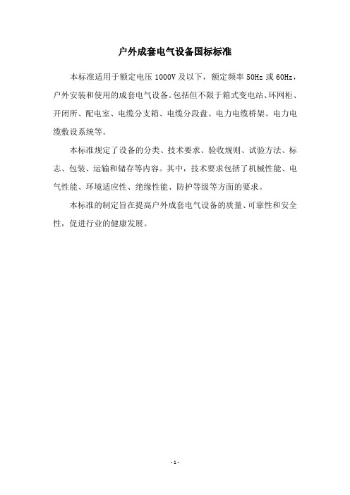
户外成套电气设备国标标准
本标准适用于额定电压1000V及以下,额定频率50Hz或60Hz,户外安装和使用的成套电气设备。
包括但不限于箱式变电站、环网柜、开闭所、配电室、电缆分支箱、电缆分段盘、电力电缆桥架、电力电缆敷设系统等。
本标准规定了设备的分类、技术要求、验收规则、试验方法、标志、包装、运输和储存等内容。
其中,技术要求包括了机械性能、电气性能、环境适应性、绝缘性能、防护等级等方面的要求。
本标准的制定旨在提高户外成套电气设备的质量、可靠性和安全性,促进行业的健康发展。
- 1 -。
160计算说明书

:同时系数;该公式来源于《煤矿电工手册(第二分册)下》第348页。
###############################################################################
=36.17<260 (A);
按计算选电缆为MCP-3X95,长度为:280 m。校验结果:合格。
6、电缆FL01的长时负荷电流计算与校验:
=190.93<260 (A);
按计算选电缆为MCP-3X95,长度为:280 m。校验结果:合格。
GL04
MYPTJ-3X50
20
6
600.5
170
(1)、按持续工作电流计算与校验
= = 61.91<170(A);校验结果:合格
(2)、按电压损失绝对值计算与校验
= = 0.733(V);
回路电压总损失: =59.848<300(V);校验结果:合格
3、高压电缆GL05的计算与校验
编号
型号
长度km
1130
6
781
170
(1)、按持续工作电流计算与校验
= = 62.77<170(A);校验结果:合格
(2)、按电压损失绝对值计算与校验
= = 47.882(V);
回路电压总损失: =106.997<300(V);校验结果:合格
3、高压电缆GL04的计算与校验
编号
型号
长度km
电压KV
负荷功率KW
长时载流量A
2、电缆DL02的长时负荷电流计算与校验:
=214.44<260 (A);
氧化锌避雷器测试仪校验标准

氧化锌避雷器测试仪校验标准一、前言在长期工作电压作用下,氧化锌避雷器阀片会出现老化现象,老化的结果是导致阻性电流和功率损耗的增加,同时阀片受潮等原因也会导致阻性电流和功率损耗增加。
因此通过检测流过氧化锌避雷器阀片的阻性电流和功率损耗,即可反映出氧化锌避雷器的劣化程度。
由于氧化锌阀片具有非线性特征的电阻,在工作电压下流过氧化锌避雷器阀片的电流具有较丰富的谐波分量,主要包括有3、5、7次等奇次波。
因此人们采用了各种方法设计的仪器来测量氧化锌避雷器的阻性电流和有功损耗,其中主要有基波法、三次谐波法、谐波法等。
由于采用的测量方法、原理不尽相同,导致各种氧化锌避雷器测试仪测量结果的可比性较差,因此有必要设计一套氧化锌避雷器测试仪检验标准,依据氧化锌避雷器阀片阻性电流和有功损耗测量的基本原理,对氧化锌避雷器测试仪进行检验,确定其测量误差。
二、设计原理HX022氧化锌避雷器测试仪校验标准采用标准源法,即有该标准器提供输出一个已知阻性电流、容性电流的标准全电流信号,同时也提供输出一个相关的标准电压信号,供给被校验避雷器测试仪测量,其测量值与标准值之差即为被检测仪器的误差。
整体标准由一台笔记本电脑通过USB接口连接到标准器上,实现对检测软件操作和下位机的控制,实现标准信号的产生、计算、显示、保存,通过高精度的D/A转换,将数字信号转换为两路模拟信号,再两路功率放大器,将信号放大(由高精密元件组成),提供电压源和电流源给被检测仪器测量。
产生标准信号的数字模型有两种。
一种数学模型是参照DL/Txxx-200x 《交流无间隙金属氧化锌避雷器阻性电流测试仪通用技术条件》,设计了一种理想的电压、电流信号。
其中电压信号为正弦波电压,f=50Hz,电流信号由阻性基波电流,阻性三次谐波电流和容性电流合成。
u=U m sinωt …..①.I=I R1sinωt+I R3sin(3ωt+π)+I C sin(ωt+π/2) …...②可根据通常U m、I R1、I R3、I C的测量范围,设定其值,通过软件计算可得电压、电流的有效值、峰值以及有功损耗。
避雷器技术标准说明
附件8:110(66)kV~750kV避雷器技术标准(附编制说明)国家电网公司目录1 总则 (1)2 引用标准 (1)3 避雷器类型 (2)3.1 金属氧化物避雷器 (2)3.2 碳化硅阀式避雷器 (2)4 使用环境条件 (2)4.1 正常使用环境条件 (2)4.2 异常使用环境条件 (3)5 避雷器选择的一般程序 (3)6 技术要求 (4)6.1 无间隙金属氧化物避雷器 (4)6.2 带串联间隙金属氧化物避雷器 (14)6.3 碳化硅阀式避雷器 (18)7 技术资料 (21)7.1 招标前用户和制造厂所需提供的技术资料 (21)7.2 合同签订后供货方所需提供的技术资料 (21)7.3 设备供货时应提供以下资料 (21)8 试验 (22)8.1 无间隙金属氧化物避雷器 (22)8.2 带串联间隙金属氧化物避雷器 (24)8.3 碳化硅阀式避雷器 (26)8.4 试验方法 (27)9 标志、包装、贮存和运输 (30)9.1 标志 (30)9.2 包装 (31)9.3 随产品提供的技术文件 (31)9.4 运输和贮存 (31)10 技术服务 (31)10.1 项目管理 (31)10.2 设备监造 (31)10.3 现场服务 (31)10.4 售后服务 (31)附录A无间隙金属氧化物避雷器的典型参数 (33)附录B避雷器用橡胶密封件的结构型式及系列参数 (34)附录C绝缘子金属附件热镀锌层技术要求 (37)附录D碳化硅阀式避雷器的电气特性 (38)附录E碳化硅阀式避雷器直流泄漏电流要求 (39)附录F碳化硅阀式避雷器用碳化硅技术要求 (40)110(66)kV~750kV避雷器技术标准1 总则1.1 为适应电网的发展要求,提高设备运行的安全可靠性,加强输变电设备技术管理,特制定本技术标准。
1.2 本标准是依据国家和国际的有关标准、规程和规范并结合近年来国家电网公司输变电设备评估分析、生产运行情况分析以及设备运行经验而制定的。
百科特奥品牌除湿机机型归类总结

百科特奥品牌除湿机机型归类总结百科特奥品牌中心,环境湿度控制技术专家,专业从事干燥通风空气处理,除湿、加湿、消毒、防潮等开发、生产,从业10余年的专业技术团队,专业设计生产除湿机,家用除湿机,工业除湿机,防爆除湿机,防爆空调,特种除湿机,百科特奥品牌中心,引进来自日本的先进的室内环境湿度控制技术和生产工艺,为你提供打造干燥舒适的室内空间环境的优质除湿机,百科特奥除湿机,具有外形高雅大方,设计新颖和具有安装维修方便等特点,百科特奥除湿机采用丹甫斯、松下、日立、大金、三菱等名牌压缩机、微电脑控制、噪声低、湿度显示、直观了然、性能优越、操作简便等众多优点。
家用、实验室、库房、车间、档案室等场所防潮除湿,抽湿袪霉,袪霉杀菌,袪霉净化最佳的选择!百科特奥除湿机执行标准:国家GB4706.32-2012、GB4706.1-2005,GB4343.1-2009,GB17625.1-2012标准,2013年10月起开始执行!百科特奥家用除湿机系列特点及参数:1.全塑设计,美观大方 2.移动万向轮,轻便放置 3.无触点水位开关,水满自动报警 4.3公斤的水箱,水满自动停机 5.自动除霜 6.环保家用型,名牌往压缩机(丹甫斯)型号除湿面积除湿量规格DH-820B 机械型20-35M2 20升/天310*280*580(mm) DH-818E 液晶型20-35M2 18升/天613×345×245(mm DH-826E 液晶型20-40M2 26升/天613×345×245(mm DH-826D 液晶型20-40M226升/天310*280*580(mm) DH-838E数码型40-65m2 38升/天440×330×640(mm) DH-858E数码型60-90m2 58升/天440×330×640(mm)百科特奥商用除湿机系列特点及参数:往复式压缩机,旋转式压缩机,脚底装有四角万向轮,可以移动自如、上前吹式出风口,下前进风口、数字显示,湿度自由控制、自动化霜功能、在环境温度低于18度一下自动化霜(合资品牌:蓝海压缩机,日立压缩机)型及号除湿面积除湿量规格DH-838D 液晶型40-65m2 38升/天440*330*640(mm)DH-858D 液晶型60-90m2 58升/天440*330*640(mm)DH-890C 数码型90-130m2 90升/天420*480*960(mm)DH-890D 液晶型90-130m2 90升/天420*480*960(mm)DH-8138C 数码型100-160M2138升/天420*480*1030(mm)DH-8138D 液晶型100-160M2138升/天420*480*1030(mm)百科特奥工业除湿机系列特点及参数:采用国际名牌大金压缩机、三菱压缩机,脚底装有四角万向轮,可以移动自如、上前吹式出风口、正前出风口,下前进风口、数码显示,湿度自由控制、自动化霜功能、在环境温度低于18度以下自动化霜北京除湿机专卖,顺义除湿机,海淀除湿机,大兴除湿机,百科特奥朝阳除湿机专卖型号除湿面积除湿量规格DH-8150C 数码型150-230m2 150升/天500*600*1020(mm) DH-8150D 液晶型150-230M2 150升/天600*600*1020(mm) DH-8168C 数码型200-280M2 168升/天405*605*1620(mm) DH-8168D 液晶型200-280M2 168升/天650*600*1950(mm) DH-8192C 数码型260-320M2 192升/天405*605*1620(mm) DH-8240C 数码型300-400M2 240升/天470*770*1700(mm) DH-8360C 数码型400-600M2360升/天520*1200*1745mm DH-8480C 数码型600-800M2480升/天520*1200*1745mm百科特奥除湿机产品型号详解:DH是除湿机英文单词:Dehumidifevs的缩写,8是我公司所有除湿机的序列编号的通用字(8喻意谐音发财),8后面的数字代表除湿机的24小时标准工况(温度30°,湿度RH80%)的除湿量,B、C、D、E只是做了产品的开发先后顺序的区分。
- 1、下载文档前请自行甄别文档内容的完整性,平台不提供额外的编辑、内容补充、找答案等附加服务。
- 2、"仅部分预览"的文档,不可在线预览部分如存在完整性等问题,可反馈申请退款(可完整预览的文档不适用该条件!)。
- 3、如文档侵犯您的权益,请联系客服反馈,我们会尽快为您处理(人工客服工作时间:9:00-18:30)。
JEWEL HILL ELECTRONIC CO.,LTDJEWEL HILL ELECTRONIC CO.,LTD.SPECIFICATIONS FORLCD MODULEModule No. GB160160BOffice Address: Rm. 518,5/F., 101 Shangbu Industrial District,HuaqiangNorthRoad, Shenzhen, ChinaTEL : (86)-755-83362489 83617492FAX: (86)-755-83286396 83365871E-mail: sales@jhlcd@Website: TABLE OF CONTENTSLCM NUMBER SYSTEM (2)1. GENERAL DESCRIPTION (3)2. FEATURES (3)3. MECHANICAL SPECIFICATION (3)4. MECHANICAL DIMENSION (4)5. MAXIMUM RATINGS (5)6. ELECTRICAL CHARACTERISTICS (5)7. MODULE FUNCTION DESCRIPTION (6)8. ELECTRO-OPTICAL CHARACTERISTICS (13)9. RELIABILITY (17)10. PRECAUTIONS FOR USING LCD MODULES (18)11. USING LCD MODULES (20)12. REVISION HISTORY (22)SAMPLE APPROVED REPORT (23)LCM Number SystemNUMBER OF CHAR. PER LINE F: FSTN; X: OTHER VERSION NUMBER: V00~V99IC TYPE:VIEWING DIRECTION:TEMPERATURE RANGE:BACKLIGHT TYPE:SERIAL NUMBER: A~ZGRAPHIC MODULEs: NUMBER OF COMMONs GRAPHIC MODULEs:NUMBER OF SEGMENTs COB & SMT LCM BACKLIGHT COLOR:CHARACTER MODULEs:CHARACTER MODULEs: NUMBER OF LINE G: REFLECTIVE,NONE BACKLIGHT A: TRANSFLECTIVE, EL BACKLIGHT B: TRANSMISSIVE, EL BACKLIGHT C: TRANSFLECTIVE, LED BACKLIGHT D: TRANSMISSIVE, LED BACKLIGHT E: TRANSFLECTIVE, CCFL BACKLIGHT F: TRANSMISSIVE, CCFL BACKLIGHT A: AMBER; B: BLUE; Y: YELLOW-GREEN R: RED; W: WHITE; O: THER COLOR N: NORMAL TEMPERATURE RANGE U: UPPER(12:00); D: DOWN(6:00)L: LEFT(9:00); R: RIGHT(3:00);A: BONDING IC, WITH CONTROLLER B: BONDING IC, WITHOUT CONTROLLER C: SMT IC, WITH CONTROLLER D: SMT IC, WITHOUT CONTROLLER O: OTHER TYPEW: BLACK-WHITE; O: OTHER G: GRAY; Y: YELLOW-GREEN; B: BLUE; LCD COLOR MODE:N: TN; H: HTN; S: STN LCD TYPE:S: SUPER WIDE TEMPERATURE RANGE W: WIDE TEMPERATURE RANGEM: MIDDLE TEMPERATURE RANGE1. GENERAL DESCRIPTIONThe GB160160B is a 160 x 160 Dots Graphics LCD module. It has a STN panel composed of160segments and 160 commons. The LCM can be easily accessed by micro-controller via parallel interface.2. FEATURESTransflective and PositiveDisplay ModeSTN(Y-G) moduleDisplay Format Graphic 160 x 160 dotsInput Data Parallel data input from MCUMultiplexing Ratio 1/160 DutyBiasBias 1/12Viewing Direction 6 O’clock(Yellow-Green)Backlight LED3. MECHANICAL SPECIFICATIONItem Specifications Unit Dimensional outline 89.2 x 85.0 x 14.6(max) mmResolution 160segs x 160coms dotsActive area 60.775(W) x 60.775(H) mmDots pitch 0.38(W)×0.38(H) mmDots size 0.355(W)×0.355 (H) mm4. MECHANICAL DIMENSION5. MAXIMUM RATINGSItem Symbol Min Max Unit NoteV DD - V ss -0.3 5.5 V Supply voltage V LCD -0.3 24.0 V Input Voltage V IN -0.3 V DD +0.3 VOperating temperature T OPR 0 +50 Storage temperature T STR -10 +60Humidity --- --- 90 %RH6. ELECTRICAL CHARACTERISTICSItem SymbolCondition Min. Typ. Max. UnitSupply Voltage Logic V DD ------ 5.0 --- VH level V IH 0.8V DD --- V DDInput VoltageL levelV IL --- V SS --- 0.2V DDVCurrent Consumption(LCD DRIVER)I DD V DD =5.0V; V LCD =19.0V, T amb =25 ;--- --- 1.5 mALCD Driving Voltage V LCDBias=1/13V LCD =V DD -V 518.7 19.0 19.3 VCurrent Consumption (With LED BackLight)I LEDV DD =5.0V;V LED =4.2V,T amb =25 ;--- --- TBD mA7. MODULE FUNCTION DESCRIPTION7.1. PIN DESCRIPTIONINTERFACE WITH CN1 & CN2:PinSymbol Description No.1 VSSPower supply for Ground (0V)2 MAC Signal for LCD Driver Output3 FLMData Input for Common ICs4 CL1Data Latch Colok5 CL2Data Shift Colok6 D37 D2Display Data Input Terminal for Segment ICs8 D19 D010 VEE Power Supply for Negative V oltage11 VDD Power supply for positive (+5V)12 V0 VLCD V oltage Regulation Terminal13 /DISPOFF Display OFF Control14 K Power Supply for LED BackLight Negative15 A Power Supply for LED BackLight Positive7.2 TIMING CHARACTERISTICS7.3 APPLICATION OF LCMLED-LED+VDD VSS VEE V0D0-D4CL1CL2M FLMCircuit Block Diagram8. ELECTRO-OPTICAL CHARACTERISTICSItem Symbol Condition Temp Min Typ. Max UnitsNote--- 19.5 ---25 18.7 19.0 19.3 LCD driving voltageV LCD = = 050 --- 18.0 --- V NOTE1Rise Time (Tr) --- --- -- Decay Time (Tf)0 --- ---- --- Rise Time (Tr) --- 225 340Decay Time (Tf) 25 --- 240 360Rise Time (Tr) --- --- -- Response TimeDecay Time (Tf)= = 0 50 --- --- --msec NOTE2Contrast Ratio Cr= = 0 255 10 --- --- NOTE4Viewing AngleRange( = 0°)(6”) = 90°(3”) =180°(12”) =270°(9”)(25 ) CR ≥245 35 25 35DegNOTE3z For panel only․Electro-Optical Characteristics Measuring Equipment(DMS501)SystemIllumination (D65)․Note 1. Definition of Driving Voltage( Vlcd) :․Note 3. Definition of Viewing Angle and :․Note 4. Definition of Contrast ratio( CR) :Brightness of Non-selected Segment (B2)Brightness of Selected Segment (B1)CR =V,maxCR,maxDriving VoltageB r i gh t n e s s (%)Brightness Curve forSelected Segment0%=90 =270Viewing Direction 6 O’clock DirectionNormal :9. RELIABILITY9.1. MTBFThe LCD module shall be designed to meet a minimum MTBF value of 50000 hours with normal. (25°C in the room without sunlight)9.2. TESTSNO. ITEM CONDITION CRITERION 1 High Temperature Operating 50 120Hrs2 Low Temperature Operating 0 120Hrs3 High Temperature/Humidity Non-Operating50 ,90%RH ,120 Hrs4 High TemperatureNon-Operating60 120Hrs5 Low TemperatureNon-Operating-10 120Hrs6 Temperature CyclingNon-Operating 0 (30Min )↔ 50 (30Min)10 CYCLESNo Defect OfOperational Function InRoom Temperature AreAllowable.IDD of LCM inPre-and post-test shouldfollow specificationNotes: Judgments should be mode after exposure in room temperature for two hours.10. PRECAUTIONS FOR USING LCD MODULES10.1. HANDLING PRECAUTIONS(1) The display panel is made of glass. Do not subject it to a mechanical shock or impact by droppingit.(2) If the display panel is damaged and the liquid crystal substance leaks out, be sure not to get any inyour mouth. If the substance contacts your skin or clothes, wash it off using soap and water.(3) Do not apply excessive force to the display surface or the adjoining areas since this may cause thecolor tone to vary.(4) The polarizer covering the display surface of the LCD module is soft and easily scratched. Handlethis polarizer carefully.(5) If the display surface becomes contaminated, breathe on the surface and gently wipe it with a softdry cloth. If it is heavily contaminated, moisten a cloth with one of the following solvents: - Isopropyl alcohol- Ethyl alcohol(6) Solvents other than those above mentioned may damage the polarizer.Especially, do not use the following:- Water- Ketone- Aromatic solvents(7) Extra care to minimize corrosion of the electrode. Water droplets, moisture condensation or acurrent flow in a high-humidity environment accelerates corrosion of the electrode.(8) Install the LCD Module by using the mounting holes. When mounting the LCD Module, makesure it is free of twisting, warping and distortion. In particular, do not forcibly pull or bend the I/Ocable or the backlight cable.(9) Do not attempt to disassemble or process the LCD Module.(10) NC terminal should be open. Do not connect anything.(11) If the logic circuit power is off, do not apply the input signals.(12) To prevent destruction of the elements by static electricity, be careful to maintain an optimumwork environment.- Be sure to ground the body when handling he LCD Module.- Tools required for assembling, such as soldering irons, must be properly grounded.-To reduce the amount of static electricity generated, do not conduct assembling and other workunder dry conditions.-The LCD Module is coated with a film to protect the display surface. Exercise care when peeling off this protective film since static electricity may be generated.10.2. STORAGE CONDITIONSWhen storing, avoid the LCD module to be exposed to direct sunlight of fluorescent lamps. For stability, to keep it away form high temperature and high humidity environment (The best condition is : 23±5°C, 45±20%RH). ESD protection is necessary for long-term storage also.10.3. OTHERSLiquid crystals solidify under low temperature (below the storage temperature range) leading to defective orientation or the generation of air bubbles (black or white). Air bubbles may also be generated if the module is subject to a low temperature.If the LCD Module have been operating for a long time showing the same display patterns the display patterns may remain on the screen as ghost images and a slight contrast irregularity may also appear.A normal operating status can be recovered by suspending use for some time. It should be noted that this phenomenon does not adversely affect performance reliability.To minimize the performance degradation of the LCD Module resulting from destruction caused by static electricity etc. exercise care to avoid holding the following sections when handling the modules.- Exposed area of the printed circuit board.- Terminal electrode sections.11. Using LCD modules11.1 LIQUID CRYSTAL DISPLAY MODULESLCD is composed of glass and polarizer. Pay attention to the following items when handling.(1) Please keep the temperature within specified range for use and storage. Polarization degradation,bubble generation or polarizer peel-off may occur with high temperature and high humidity.(2) Do not touch, push or rub the exposed polarizers with anything harder than a HB pencil lead (glass,tweezers, etc).(3) N-hexane is recommended for cleaning the adhesives used to attach front/rear polarizers andreflectors made of organic substances, which will be damaged by chemicals such as acetone, toluene, toluene, ethanol and isopropyl alcohol.(4) When the display surface becomes dusty, wipe gently with absorbent cotton or other soft materiallike chamois soaked in petroleum ether. Do not scrub hard to avoid damaging the display surface.(5) Wipe off saliva or water drops immediately, contact with water over a long period of time maycause deformation or color fading.(6) Avoid contacting oil and fats.(7) Condensation on the surface and contact with terminals due to cold will damage, stain orpolarizers. After products are tested at low temperature they must be warmed up in a container before coming is contacting with room temperature air.(8) Do not put or attach anything on the display area to avoid leaving marks on.(9) Do not touch the display with bare hands. This will stain the display area and degrade insulationbetween terminals (some cosmetics are determinate to the polarizers).(10)As glass is fragile, it tends to become or chipped during handling especially on the edges. Pleaseavoid dropping or jarring.11.2 INSTALLING LCD MODULEAttend to the following items when installing the LCM.(1) Cover the surface with a transparent protective plate to protect the polarizer and LC cell.(2) When assembling the LCM into other equipment, the spacer to the bit between the LCM and thefitting plate should have enough height to avoid causing stress to the module surface, refer to the individual specifications for measurements. The measurement tolerance should be ±0.1mm.11.3 ELECTRO-STATIC DISCHARGE CONTROLSince this module uses a CMOS LSI, the same careful attention should be paid for electrostatic discharge as for an ordinary CMOS IC.(1) Make certain that you are grounded when handing LCM.(2) Before removing LCM from its packing case or incorporating it into a set, be sure the module andyour body have the same electric potential.(3) When soldering the terminal of LCM, make certain the AC power source for the soldering irondoes not leak.(4) When using an electric screwdriver to attach LCM, the screwdriver should be of groundpotentiality to minimize as much as possible any transmission of electromagnetic waves produced sparks coming from the commutator of the motor.(5) As far as possible, make the electric potential of your work clothes and that of the workbenches tothe ground potential.(6) To reduce the generation of electro-static discharge, be careful that the air in the work is not toodried. A relative humidity of 50%-60% is recommended.11.4 PRECAUTIONS FOR OPERATION(1) Viewing angle varies with the change of liquid crystal driving voltage (Vo). Adjust Vo to showthe best contrast.(2) Driving the LCD in the voltage above the limit will shorten its lifetime.(3) Response time is greatly delayed at temperature below the operating temperature range. However,this does not mean the LCD will be out of the order. It will recover when it returns to the specified temperature range.(4) If the display area is pushed hard during operation, the display will become abnormal. However, itwill return to normal if it is turned off and then on.(5) Condensation on terminals can cause an electrochemical reaction disrupting the terminal circuit.Therefore, this product must be used and stored within the specified condition of 23±5°C, 45±20%RH.(6) When turning the power on, input each signal after the positive/negative voltage becomes stable.11.5 SAFETY(1) It is recommended to crush damaged or unnecessary LCDs into pieces and wash them off withsolvents such as acetone and ethanol, which should later be burned.(2) If any liquid leaks out of a damaged glass cell and comes in contact with the hands, wash offthoroughly with soap and water.12. REVISION HISTORYrecord Date Version Reviseversion 06-05-241.0 Original2.0 Change contact mode 06-08-04SAMPLE APPROVED REPORT。