Miltefosine_58066-85-6_DataSheet_MedChemExpress
美国安全数据表300001009080-酮化剂ME-588BK产品说明说明书

USA SAFETY DATA SHEET1. CHEMICAL PRODUCT AND COMPANY IDENTIFICATIONProduct name:THERMOSET ME-588 BKProduct Use/Class: EncapsulantLORD Corporation111 LORD DriveCary, NC 27511-7923 USATelephone: 814 868-3180Non-Transportation Emergency: 814 763-2345Chemtrec 24 Hr Transportation Emergency No.800 424-9300 (Outside Continental U.S. 703 527-3887)EFFECTIVE DATE: 02/26/20212. HAZARDS IDENTIFICATIONGHS CLASSIFICATION:Acute toxicity DermalCategory 4 - 92.0% of the mixture consists of ingredient(s) of unknown toxicity.Skin corrosion/irritation Category 2Serious eye damage/eye irritation Category 2ASkin sensitization Category 1Carcinogenicity Category 2Hazardous to the aquatic environment - chronic hazard Category 2GHS LABEL ELEMENTS:Symbol(s)Signal WordW ARNINGHazard StatementsHarmful in contact with skin.Causes skin irritation.Causes serious eye irritation.May cause an allergic skin reaction.Suspected of causing cancer.Toxic to aquatic life with long lasting effects.Precautionary StatementsPreventionObtain special instructions before use.Do not handle until all safety precautions have been read and understood.Wear protective gloves/protective clothing/eye protection/face protection.Use personal protective equipment as required.Avoid breathing dust/fume/gas/mist/vapors/spray.Wash thoroughly after handling.Contaminated work clothing should not be allowed out of the workplace.Avoid release to the environment.ResponseCall a POISON CENTER or doctor/physician if you feel unwell.Specific treatment (see supplemental first aid instructions on this label).300001009080IF ON SKIN: Wash with plenty of soap and water.If skin irritation or rash occurs: Get medical advice/attention.IF IN EYES: Rinse cautiously with water for several minutes. Remove contact lenses, if present and easy to do.Continue rinsing.Take off contaminated clothing and wash before reuse.Collect spillage.StorageStore locked up.Disposal:Dispose of contents/container in accordance with waste/disposal aws and regulations of your country or particular locality.Other Hazards:This product contains component(s) which have the following warnings; however based on the GHS classification criteria of your country or locale, the product mixture may be outside the respective category(s).Acute: May cause respiratory tract irritation. May cause allergic respiratory reaction.May be harmful if swallowed.Ingestion is not an expected route of entry in industrial or commercial uses.Chronic: Contains an epoxy resin which is a possible mutagen, based on animal data. Prolonged exposure to the silica-containing sanding dust of this product could cause long-term lung damage. Crystalline silica is classified by IARC and NTP as a known human carcinogen as a respirable dust. The silica in LORD products is not in a form that can be inhaled and presents no risk to the end user. No exposure is expected during normal use of this product.Sanding or abrading the cured materials is not recommended. Wear appropriate respiratory protection if exposure to dusts is possible.withheld.FIRST AID - EYE CONTACT: Flush eyes immediately with large amount of water for at least 15 minutes holding eyelids open while flushing. Get prompt medical attention.FIRST AID - SKIN CONTACT: Flush contaminated skin with large amounts of water while removing contaminated clothing. Wash affected skin areas with soap and water. Get medical attention if symptoms occur.FIRST AID - INHALATION: Move person to fresh air. Restore and support continued breathing. If breathing is difficult, give oxygen. Get immediate medical attention.FIRST AID - INGESTION: If swallowed, do not induce vomiting. Call a physician or poison control center immediately for further instructions. Never give anything by mouth if victim is rapidly losing consciousness, unconscious or convulsing.SUITABLE EXTINGUISHING MEDIA: Carbon Dioxide, Dry Chemical, Foam, Water FogUNSUITABLE EXTINGUISHING MEDIA: Not determined for this product.SPECIFIC HAZARDS POSSIBLY ARISING FROM THE CHEMICAL: Keep containers tightly closed. Closed containers may rupture when exposed to extreme heat. Use water spray to keep fire exposed containers cool. During a fire, irritating and/or toxic gases and particulate may be generated by thermal decomposition or combustion.SPECIAL PROTECTIVE EQUIPMENT AND PRECAUTIONS FOR FIRE-FIGHTERS: Wear full firefighting protective clothing, including self-contained breathing apparatus (SCBA). If water is used, fog nozzles are preferable.PERSONAL PRECAUTIONS, PROTECTIVE EQUIPMENT AND EMERGENCY PROCEDURES: Avoid breathing vapors. Avoid contact. Use appropriate respiratory protection for large spills or spills in confined area.ENVIRONMENTAL PRECAUTIONS: Do not contaminate bodies of water, waterways, or ditches, with chemical or used container.METHODS AND MATERIALS FOR CONTAINMENT AND CLEANUP: Notify appropriate authorities if necessary. Avoid contact. Keep non-essential personnel away from spill area. Scoop spilled material into an appropriate container for proper disposal. (If necessary, use inert absorbent material to aid in containing the spill).HANDLING: Keep closure tight and container upright to prevent leakage. Avoid skin and eye contact. Wash thoroughly after handling. Do not handle until all safety precautions have been read and understood. Empty containers should not be re-used. Use with adequate ventilation.STORAGE: Store only in well-ventilated areas. Keep container closed when not in use. Avoid excessive heat. Avoid moisture contamination. Product should be stored frozen for best shelf life. See LORD Technical Datasheet for product specific storage instructions.INCOMPATIBILITY: Strong acids and bases.Engineering controls: Sufficient ventilation in pattern and volume should be provided in order to maintain air contaminant levels below recommended exposure limits.PERSONAL PROTECTION MEASURES/EQUIPMENT:RESPIRATORY PROTECTION: Use a NIOSH approved air-purifying organic vapor respirator if occupational limits are exceeded. For emergency situations, confined space use, or other conditions where exposure limits may be greatly exceeded, use an approved air-supplied respirator. For respirator use observe OSHA regulations (29CFR 1910.134) or use in accordance with applicable laws and regulations of your country or particular locality.SKIN PROTECTION: Use neoprene, nitrile, or rubber gloves to prevent skin contact.EYE PROTECTION: Use safety eyewear including safety glasses with side shields and chemical goggles where splashing may occur.OTHER PROTECTIVE EQUIPMENT: Use disposable or impervious clothing if work clothing contamination is likely. Remove and wash contaminated clothing before reuse.HYGIENIC PRACTICES: Wash hands before eating, smoking, or using toilet facility. Food or beverages should not be consumed anywhere this product is handled or stored. Wash thoroughly after handling.Typical values, not to be used for specification purposes.ODOR: Characteristic VAPOR PRESSURE: N.D.APPEARANCE: Black VAPOR DENSITY: Heavier than Air PHYSICAL STATE: Paste LOWER EXPLOSIVE LIMIT: Not ApplicableUPPER EXPLOSIVE LIMIT: Not ApplicableFLASH POINT:≥ 201 °F, 93 °CSetaflash Closed CupBOILING RANGE: N.A.EVAPORATION RATE: Slower than n-butyl-acetate AUTOIGNITION TEMPERATURE:N.D.DENSITY: 1.53 g/cm3 (12.77 lb/gal) DECOMPOSITION TEMPERATURE:N.D. VISCOSITY, DYNAMIC: ≥18,350 mPa.s @ 25 °C ODOR THRESHOLD: N.D.VISCOSITY, KINEMATIC: ≥11,993 mm2/s @ 25 °CSOLUBILITY IN H2O: Insoluble VOLATILE BY WEIGHT: 0.02 %pH: N.A.VOLATILE BY VOLUME: 0.03 %FREEZE POINT: N.D. VOC CALCULATED: 0 lb/gal, 0 g/l COEFFICIENT OF WATER/OILN.D.DISTRIBUTION:LEGEND: N.A. - Not Applicable, N.E. - Not Established, N.D. - Not DeterminedHAZARDOUS POLYMERIZATION: Hazardous polymerization will not occur under normal conditions.STABILITY: Product is stable under normal storage conditions.CONDITIONS TO AVOID: Moisture.; High temperatures.; Storage temperatures above 40F will cause the material to react and solidify.INCOMPATIBILITY: Strong acids and bases.HAZARDOUS DECOMPOSITION PRODUCTS: Carbon monoxide, carbon dioxide, oxides of nitrogen, Organic acid vapors, Aldehydes, Hydrogen cyanideEXPOSURE PATH: Refer to section 2 of this SDS.SYMPTOMS:Refer to section 2 of this SDS.TOXICITY MEASURES:Germ cell mutagenicity: No classification proposedCarcinogenicity: Category 2 - Suspected of causing cancer.Components contributing to classification: Epoxy resin.Reproductive toxicity: No classification proposedPERSISTENCE AND DEGRADABILITY:Not determined for this product.BIOACCUMULATIVE: Not determined for this product.MOBILITY IN SOIL: Not determined for this product.OTHER ADVERSE EFFECTS: Not determined for this product.DISPOSAL METHOD: Disposal should be done in accordance with Federal (40CFR Part 261), state and local environmental control regulations. If waste is determined to be hazardous, use licensed hazardous waste transporter and disposal facility.US DOT RoadProper Shipping Name: Environmentally hazardous substances, liquid, n.o.s.Hazard Class: 9SECONDARY HAZARD: NoneUN/NA Number: 3082Packing Group: IIIEmergency Response Guide Number: 171For US DOT non-bulk road shipments this material may be classified as NOT REGULATED. For the most accurate shipping information, refer to your transportation/compliance department regarding changes inpackage size, mode of shipment or other regulatory descriptors.IATA CargoPROPER SHIPPING NAME: Environmentally hazardous substance, liquid, n.o.s.Hazard Class: 9HAZARD CLASS: NoneUN NUMBER: 3082PACKING GROUP: IIIEMS: 9LIMDGPROPER SHIPPING NAME: Environmentally hazardous substance, liquid, n.o.s.Hazard Class: 9HAZARD CLASS: NoneUN NUMBER: 3082PACKING GROUP: IIIEMS: F-AThe listed transportation classification applies to non-bulk shipments. It does not address regulatory variations due to changes in package size, mode of shipment or other regulatory descriptors. For the most accurate shipping information, refer to your transportation/compliance department.U.S. FEDERAL REGULATIONS: AS FOLLOWS:SARA SECTION 313This product contains the following substances subject to the reporting requirements of Section 313 of Title III of the Superfund Amendment and Reauthorization Act of 1986 and 40 CFR part 372.:NoneTOXIC SUBSTANCES CONTROL ACT:INVENTORY STATUSThe chemical substances in this product are on the TSCA Section 8 Inventory.EXPORT NOTIFICATIONThis product contains the following chemical substances subject to the reporting requirements of TSCA 12(B) if exported from the United States:Chemical Name CAS NumberEpoxy resin PROPRIETARYUnder HazCom 2012 it is optional to continue using the HMIS rating system. It is important to ensure employees have been trained to recognize the different numeric ratings associated with the HazCom 2012 and HMIS schemes.HMIS RATINGS - HEALTH: 2* FLAMMABILITY: 1 PHYSICAL HAZARD: 1* - Indicates a chronic hazard; see Section 2Revision: Section 1, Section 2, Section 3, Section 8, Section 11, Section 12Effective Date: 02/26/2021The information contained herein is, to the best of our knowledge and belief, accurate. However, since the conditions of handling and use are beyond our control, we make no guarantee of results, and assume no liability for damages incurred by use of this material. It is the responsibility of the user to comply with all applicable federal, state and local laws and regulations.。
Memosens Wave CAS80E 全光谱传感器说明书
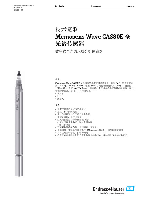
应用Memosens Wave CAS80E 全光谱传感器支持多参数测量,包括SAC、光谱衰减系数、TOCeq、CODeq、BODeq、浊度(TU)、悬浮颗粒物浓度(TSS)、硝酸盐(NO3-N)、色度(APHA Hazen)等参数。
全光谱传感器可靠输出测量值,高效实施过程监测,适用于下列应用场合:•饮用水•污水•地表水优势•针对过程条件优化传感器设计•提供三种不同的光程•钛材传感器可以在严苛工况中使用•蓝宝石窗口,长使用寿命•全光谱传感器自带数据处理功能:•信号传输几乎不受干扰因素的影响•响应时间短•不间断检测峰值负载,早期识别,无延迟•开箱即用:支持标准通信协议(Memosens 技术),传感器即插即用•采用压缩空气清洗,长维护周期•按照特定应用要求和用户需求执行传感器标定,实验室和现场标定均可行Products Solutions Services技术资料Memosens Wave CAS80E 全光谱传感器数字式全光谱水质分析传感器TI01522C/28/ZH/03.22-00715973202022-04-25Memosens Wave CAS80E 全光谱传感器2Endress+Hauser功能与系统设计测量原理全光谱传感器由以下部件组成:•电源•频闪光源高压发生器•氙气频闪光源•监测二极管•测量池•光谱计:紫外光(UV)/可见光(VIS),波长范围200 … 800 nm •微处理器1产品设计1光谱分析单元2透镜3监测二极管4光源5测量池光源发射光线,波束穿透透镜,射向介质。
测量池中注有待分析的样品。
进入光谱分析单元的波束经处理,转换成可测量的电信号。
双波束工作原理,补偿光源变化→ 1, 2。
全光谱传感器基于物质吸收特定波长的电磁辐射的原理工作,分析记录的光谱,测定测量参数。
2不同参数对应吸收光谱范围λ波长范围A 吸光度B 紫外光(UV)C 可见光(VIS)a 254 nm,SAC,SSK 1硝酸盐2水质指标:BODeq、CODeq、TOCeq、DOCeq 3色度、浊度、悬浮颗粒物浓度Memosens Wave CAS80E 全光谱传感器Endress+Hauser 3每种分子都有特定的吸收光谱。
Mellanox QSFP+ 直接附接铜线(DAC)线缆商品介绍说明书

Mellanox ® QSFP+ direct attach copper (DAC) cables provide robust connections for leading edge 56Gb/s InfiniBand or 40GbE Ethernet systems. The cables consist of four lanes each operating at data rates of up to 14.0625Gb/s.Passive copper cables require no additional power to ensure quality connectivity. The cables are compliant with SFF-8685 specifications and provide connectivity between devices using QSFP+ ports. Each QSFP+ port comprises an EEPROM providing product information, which can be read by the host system.This integrated cable solution provides reliable transport for aggregate data rates of up to 56Gb/s Virtual Protocol Interconnect (VPI). Optimizing systems to operate with Mellanox’s 56Gb/s passive copper cables significantly reduces power consumption and EMI emission, eliminating the use of enterprise data center (EDC) hosts.Mellanox’s unique quality passive copper cable solutions provide power-efficient connectivity for short distance interconnects. They enable higher port bandwidth, density and configurability at a low cost and reduced power requirement in the data centers.Rigorous cable production testing ensures best out-of-the-box installation experience, performance and durability.Table 1 - Absolute Maximum RatingsTable 2 - Operational Specifications56Gb/s and 40GbE QSFP + Direct Attach Copper CablesINTERCONNECT PRODUCT BRIEFMC22061xx-00x | MC22071xx-0xx | MC22101xx-00x | MCP170L-F0xx | MCP1700-B0xxx†T able 3 - Electrical SpecificationsT able 4 - Cable Mechanical SpecificationsNote 1. See Figure 1 for the cable length definition.Note 2: *The pulltab color is black, instead of the standard blue pulltab.Note 3: The minimum bending space is the distance from the system panel to the edge of the cable bend with the minimum assembly bending radius. This corresponds to the distance from the switch panel to the rack door.Note 4: The minimum assembly bending radius (close to the connector) is 10x the cable’s outer diameter. The repeated bend (far from the connector) is also 10x the cable’s outer diameter. The single bend (far from the connector) is 5x the cable’s outer diameter.Figure 1. Cable Length DefinitionMechanical Schematics350 Oakmead Parkway, Suite 100, Sunnyvale, CA 94085Tel: 408-970-3400 • Fax: © Copyright 2018. Mellanox Technologies. All rights reserved.Mellanox, Mellanox logo and LinkX are registered trademarks of Mellanox Technologies, Ltd. Warranty InformationMellanox LinkX direct attach copper cables include a 1 year limited hardware warranty, which covers parts repair or replacement.Table 5 - Part Numbers and DescriptionsNote: The standard pulltab color is blue; cables with a black pulltab are indicated accordingly.。
Omron K8AB-PA 三相偏差、相序、失相保护器说明书

c All Rights Reserved
9419061-9 C
Precautions for Safe Use
Make sure to follow the instructions below to ensure safety.
1. Do not use or keep this product in the following environments.
ʢ6ʣThe type K8AB-PA can only detect phase interrupt -ion when the interruption occurs on the side where power supply exists from the point of connection, and interruption on the loading side cannot be detected.
install switches or circuit breakers that conform to relevant requirements of IEC60947-1 and IEC60947-3, and label them appropriately. 11. For DC input, use a SELV power-supply capable of overcurrent protection. Specifically, a SELV powersupply has a double or reinforced insulation for input and output, and output voltage of 30Vr.m.s with 42.4V at peak or DC60V maximum. Recommended power-supply : Model S8VS-06024˘ (Omron product) 12. Do not turn a setting volume beyond the scope of movement.
特克莫瑞克580系列双脉冲采样波形显示器说明书

RETIREMENT TRUST BLDG .
3.W. MILLIKAN WAY
Tek Traffic Manager To Serve On Panel At Pacific
Harold Fritzler , Freight Traffic man ager , will serve on a panel at the April 2 meeting of the 8th Annual Business Sem inar . The seminar , sponsored by the Busi ness Economics department of Pacific university , is titled " The Best Moves in Transportation .” The panel will discuss Traffic Management Problems in Indus
In are
Uanviatsila. blSei.x
other
vertical
plug- in
units
Tektronix Display
Tekweek Vol . 2 , No. 50 Tektronix , Inc. , Beaverton , Oregon March 30 , 1962
The annual IRE show, the electronics
Emerson Wireless THUM 适配器数据手册说明书
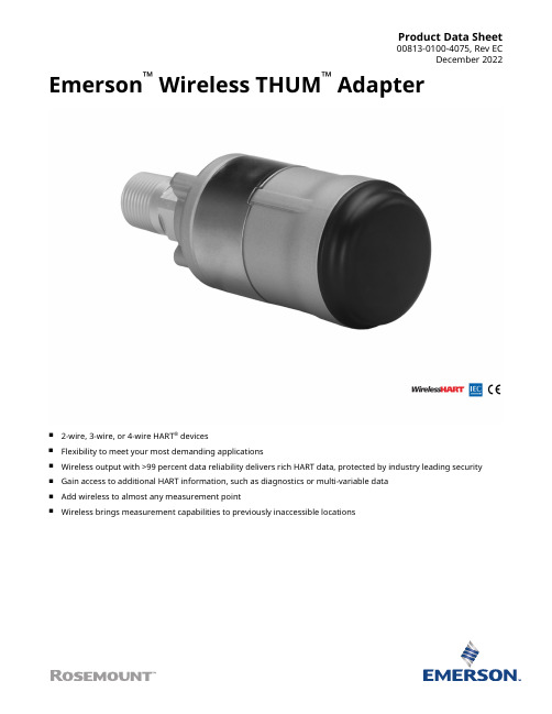
Product Data Sheet00813-0100-4075, Rev ECDecember 2022 Emerson™ Wireless THUM™ Adapter■2-wire, 3-wire, or 4-wire HART® devices■Flexibility to meet your most demanding applications■Wireless output with >99 percent data reliability delivers rich HART data, protected by industry leading security■Gain access to additional HART information, such as diagnostics or multi-variable data■Add wireless to almost any measurement point■Wireless brings measurement capabilities to previously inaccessible locationsIEC 62591(Wireless HART®)...the industry standardSelf-organizing, adaptive mesh routing■No wireless expertise required. Devices automatically find the best communication paths.■Network continuously monitors paths for degradation and repairs itself.■Adaptive behavior provides reliable, hands-off operation and simplifies network deployments, expansion, and reconfiguration.■Supports both star and mesh topologies. Industry standard radio with channel hopping■Standard IEEE 802.15.4 radios■ 2.4 GHz ISM band sliced into 16 radio channels■Continually “hop” across channels to avoid interference and increase reliability■Direct sequence spread spectrum (DSSS) technology delivers high reliability in challenging radio environmentSelf-healing network■The self-organizing, self-healing network manages multiple communication paths for any given device. If an obstruction is introduced into the network, data will continue to flow because the device already has other established paths. The network will then lay in more communication paths as needed for that device. Seamless integration to existing hosts■Transparent and seamless integration■Same control system applications■Gateways connect using industry protocolsContentsIEC 62591(Wireless HART®)...the industry standard. (2)Wireless THUM Adapter (3)Ordering Information (4)Specifications (7)Product Certifications (10)Dimensional Drawings (15)THUM Adapter December 2022Wireless THUM AdapterDevice specifications■Approvals: FM, CSA, ATEX, IECEx■Input: Either 2-wire, 3-wire, or 4-wire HART 5.0 device■SmartPower™: Power scavenging technology (no battery required)■Minimum load on loop 250 OhmsEnable enhanced valve capabilities■Online, in-service valve testing through AMS ValveLink SNAP-ON™Application.■Monitor alerts such as travel deviation with AMS Device Manager, supply pressure, and electronics health.■Trend actual valve position.Gain access to advanced instrument diagnostics■Rosemount™ 3051S with Advanced Process Diagnostics■Micro Motion™ Coriolis Meter Verification with optional AMS Meter Verification SNAP-ON■Rosemount Radar Echo Curve■Rosemount Magnetic Flow Meter Verification with AMS Device ManagerEfficiently gather data from multivariable devices■Rosemount 3051S MultiVariable™ Transmitter and Rosemount 3095 Mass Flow Transmitters■Rosemount 3300 and 5300 Radar Level Transmitters■Micro Motion Coriolis Meters■Rosemount TankRadar™ Rex and TankRadar Pro■Rosemount Magnetic Flow Meter■Rosemount MultiVariable Vortex Flow MeterMake any HART device wireless access new measurement information ■Level■Flow■Valves■Liquid and Gas Analytical■Pressure■TemperatureRemotely manage devices and monitor health with AMS Device Manager■Reduce troubleshooting time■As found, as left data■Calibration trackingDecember 2022THUM AdapterOrdering InformationOnline product configuratorMany products are configurable online using our Product Configurator. Select the Configure button or visit our website to start. With this tool's built-in logic and continuous validation, you can configure your products more quickly and accurately.Specifications and optionsSee the Specifications and options section for more details on each configuration. Specification and selection of product materials, options, or components must be made by the purchaser of the equipment. See the Material selection section for more information.Model codesModel codes contain the details related to each product. Exact model codes will vary; an example of a typical model code is shown in Figure 1.Figure 1: Model Code Example1.Required model components (choices available on most)2.Additional options (variety of features and functions that may be added to products)Optimizing lead timeThe starred offerings (★) represent the most common options and should be selected for the fastest delivery times.The nonstarred offerings are subject to additional delivery lead time.Required model components ModelRequires THUM Connection Box.THUM AdapterDecember 2022December 2022THUM Adapter OutputHousingMounting connectionPlantWeb functionalityCertificationTHUM Adapter December 2022Wireless update rate, operating frequency, and protocolOmni-directional antenna and SmartPower™ solutionsAccessoriesDecember 2022THUM Adapter SpecificationsFunctional specificationsInputAny 2-wire, 3-wire, or 4-wire HART powered deviceOutputIEC 62591 (Wireless HART®)Humidity limits0 - 100% relative humidityUpdate rateUser selectable, eight seconds to 60 minutesPhysical specificationsMaterial selectionEmerson provides a variety of Rosemount products with various product options and configurations, including materials of construction that can be expected to perform well in a wide range of applications. The Rosemount product information presented is intended as a guide for the purchaser to make an appropriate selection for the application. It is the purchaser’s sole responsibility to make a careful analysis of all process parameters (such as all chemical components, temperature, pressure, flow rate, abrasives, contaminants, etc.), when specifying product, materials, options, and components for the particular application. Emerson is not in a position to evaluate or guarantee the compatibility of the process fluid or other process parameters with the product, options, configuration, or materials of construction selected.Electrical connectionsThe THUM Adapter is connected into a powered 4–20 mA loop, powering itself by scavenging power. The THUM Adapter causes a voltage drop across the loop. The drop is linear from 2.25 V at 3.5 mA to 1.2 V at 25 mA, but does not effect the 4–20 mA signal on the loop. Under fault conditions, the maximum voltage drop is 2.5 V.Power supplyMinimum load on loop 250 OhmsTo maintain normal operating functions of the sub-device, the power in the loop must have at least a 2.5 V margin at a 250 Ω load.Limit the power supply to 0.5 A maximum.Limit the power supply to 30 Vdc maximum.Field Communicator connectionsUtilize wired device HART connectionsTHUM Adapter December 2022 Materials of constructionEnclosure■Housing option D: Low-copper aluminum■Housing option E: 316 SST■Paint: Polyurethane■M20 conduit adapter: SST■M20 conduit adapter O-ring: Buna-NAntennaPolybutadine terephthalate (PBT)/Polycarbonate (PC) integrated omni directional antennaWeight■THUM Adapter only AL: 0.65 lb (0.29 kg)■THUM Adapter only SST: 1.1 lb (0.5 kg)■AL THUM Adapter with AL remote kit: 3.2 lb (1.45 kg)■SST THUM Adapter with SST remote kit: 5.8 lb (2.65 kg)■AL THUM Adapter with M20 conduit adapter: 0.85 lb (0.038 kg)■SST THUM Adapter with M20 conduit adapter: 1.3 lb (0.59 kg)Enclosure ratingsHousing option code D and remote mount kits are enclosure Type 4X and IP66.MountingThe THUM Adapter may be attached directly to the conduit of any 2-wire or 4-wire HART device or mounted remotely by using remote mount kit.December 2022THUM Adapter Performance specificationsElectroMagnetic Compatibility (EMC)Meets all industrial environments of EN61326 and NAMUR NE-21 when installed with shielded wiring. The sub-device must also use shielded wiring for installation. Maximum deviation ≤1% span during EMC disturbance(1).Vibration effectOutput unaffected when tested per the requirements of IEC60770-1 field with general application or pipeline with low vibration level (10–60 Hz 0.15 mm displacement peak amplitude/60–500 Hz 2 g).When the THUM Adapter is used on wired devices that are subject to vibration levels greater than 2 g, it is recommended that the THUM Adapter be remotely mounted using the remote mount kit.Temperature limitsAmbient temperature-40 to 85 °C (-40 to 185 °F)Storage temperature-40 to 85 °C (-40 to 185 °F)(1)During the surge event, device may exceed maximum EMC deviation limit or reset; however, device will self-recover and return to normaloperation within specified start-up time.THUM Adapter December 2022 Product CertificationsRev 2.9European Directive InformationA copy of the EU Declaration of Conformity can be found at the end of the Quick Start Guide. The most recent revision of the EU Declaration of Conformity can be found at /Rosemount.Ordinary location certification from FM ApprovalsAs standard, the transmitter has been examined and tested to determine that the design meets the basic electrical, mechanical, and fire protection requirements by FM Approvals, a nationally recognized test laboratory (NRTL) as accredited by the Federal Occupational Safety and Health Administration (OSHA).Telecommunication compliance (for wireless products only)All wireless devices require certification to ensure that they adhere to regulations regarding the use of the RF spectrum. Nearly every country requires this type of product certification.Emerson is working with governmental agencies around the world to supply fully compliant products and remove the risk of violating country directives or laws governing wireless device usage.FCC and IC (for wireless products only)This device complies with Part 15 of the FCC Rules. Operation is subject to the following conditions: This device may not cause harmful interference. This device must accept any interference received, including interference that may cause undesired operation. This device must be installed to ensure a minimum antenna separation distance of 20 cm from all persons.Installing equipment in North AmericaThe US National Electrical Code® (NEC) and the Canadian Electrical Code (CEC) permit the use of Division marked equipment in Zones and Zone marked equipment in Divisions. The markings must be suitable for the area classification, gas, and temperature class. This information is clearly defined in the respective codes.USAE5 USA ExplosionproofCertificate CSA 2174201Standards FM Class 3600 - 2011, FM Class 3615 - 2006, ANSI/UL 61010-1 3rd EditionMarkings Class I, Division 1, Groups A, B, C and D; T5, T6; Type 4X and IP66 (–50 °C≤ T a≤ +70 °C)December 2022THUM Adapter I5 USA Intrinsically Safe (IS) and Non-incendiveCertificate3036224Standards FM Class 3600 - 1998, FM Class 3610 - 2007, FM Class 3611 - 2004, FM Class 3810 - 2005, NEMA 250 -2003, IEC 60529 - 2004Markings IS CL I, DIV 1, GP A, B, C, D; CL II, DIV 1, GP E, F, G; Class III; Class 1, Zone 0, AEx ia IIC T4; NI CL I, DIV 2, GP A, B, C, D T4; T4(–50 °C≤ T a≤ +70 °C) when connected per Rosemount drawing 00775-0010;Type 4X/IP66CanadaE6 Canada ExplosionproofCertificate CSA 2174201Standards CAN/CSA C22.2 No. 0-M91, CSA Std. C22.2 No. 30-M1986, CAN/CSA-C22.2 No. 94-M91, CAN/CSA-C22.2 No.61010-1-12, CSA Std. C22.2 No. 60529Markings Class I, Division 1, Groups A, B, C and D; T5, T6; Type 4X and IP66 (–50 °C≤ T a≤ +70 °C)I6 Canada Intrinsically SafeCertificate2174201Standards CAN/CSA C22.2 No. 0-M91 (R2001), CAN/CSA C22.2 No. 94-M91 (R2001), CSA Std C22.2 No. 142-M1987, CAN/CSA C22.2 No.157-92, CSA Std C22.2 No. 213-M1987, C22.2 No. 60529Markings Intrinsically Safe Class I, Division 1, Groups A, B, C, D T3C; Suitable for use in Class I, Division 2, Groups A, B, C, D T3C; T3C(–50 °C≤ T a≤ +70 °C) when installed per Rosemount drawing 00775-0012;Type 4X/IP66EuropeI1 ATEX Intrinsic SafetyCertificate Baseefa09ATEX0125XStandards IEC 60079-0:2011; EN60079-11:2012;Markings≤ T a≤ +70 °C)Special Conditions for Safe Use (X):1.The surface resistivity of the antenna is greater than 1GΩ. To avoid electrostatic charge build-up, it must not berubbed or cleaned with solvents or dry cloth.2.The Rosemount 775 enclosure may be made of aluminum alloy and given a protective polyurethane paint finish;however, care should be taken to protect it from impact or abrasion if located in zone 0.N1 ATEX Type nCertificate Baseefa09ATEX0131Standards IEC 60079-0:2012 + A11:2013, EN 60079-15:2010;THUM Adapter December 2022 Markings≤ T a≤ +70 °C) IP66InternationalI7 IECEx Intrinsic SafetyCertificate IECEx BAS 09.0050XStandards IEC 60079-0:2011, IEC 60079-11:2011Markings Ex ia IIC T4 Ga, T4(–50 °C≤ T a≤ +70 °C) IP66Special Conditions for Safe Use (X):1.The surface resistivity of the antenna is greater than 1 GΩ. To avoid electrostatic charge build-up, it must not berubbed or cleaned with solvents or dry cloth.2.The Rosemount 775 enclosure may be made of aluminum alloy and given a protective polyurethane paint finish;however, care should be taken to protect it from impact or abrasion if located in zone 0.N7 IECEx Type nCertificate IECEx BAS 09.0058Standards IEC 60079-0:2011, IEC 60079-15:2010;Markings Ex nA IIC T4 Gc, T4(–50 °C≤ T a≤ +70 °C) IP66BrazilI2 INMETRO Intrinsic SafetyCertificate UL-BR 15.0089XStandards ABNT NBR IEC 60079-0:2013, ABNT NBR IEC 60079-11:2013Markings Ex ia IIC T4 Ga (–50 °C≤ T a≤ +70 °C), IP66Special Conditions for Safe Use (X):1.The surface resistivity of the antenna is greater than 1 GΩ. To avoid electrostatic charge build-up, it must not berubbed or cleaned with solvents or dry cloth.2.The enclosure may be made of aluminum alloy and given a protective polyurethane paint finish; special caremust be taken to minimize the risk of impact or friction of the housing which can cause the generation ofsparks.N2 INMETRO Type nCertificate UL-BR 15.0027Standards ABNT NBR IEC 60079-0:2008 + Errata 1:2011, IEC 60079-15:2012Markings Ex nA IIC T4 Gc (–50 °C≤ T a≤ +70 °C) IP66December 2022THUM Adapter ChinaI3 NEPSI Instrinsic SafetyCertificate:GYJ20.1388XStandards:GB3836.1 – 2010, GB3836.4 – 2010, GB3836.20-2010Markings:Ex ia IIC T4 Ga, -50 ~ +70 °CSpecial Conditions for Safe Use (X):1.See certificate for special conditions.JapanI4 CML Intrinsically SafeCertificate CML19JPN2107XMarkings Ex ia IIC T4 Ga, -50 °C~ +70 °CSpecial Conditions for Safe Use (X):1.See certificate for special conditions.EAC - Belarus, Kazakhstan, RussiaIM Technical Regulation Customs Union (EAC) Intrinsic SafetyCertificate TC RU C-US.AA87.B.00993Markings0Ex ia IIC T4 Ga X; T4 (–50 °C≤ T a≤ +70 °C) IP66Special Conditions for Safe Use (X):1.See certificate for special conditions.NM Technical Regulation Customs Union (EAC) Type nCertificate TC RU C-US.AA87.B.00993Markings2Ex nA IIC T4 Gc X; T4 (–50 °C≤ T a≤ +70 °C) IP66Special Conditions for Safe Use (X):1.See certificate for special conditions.THUM Adapter December 2022 Republic of KoreaIP Korea (KOSHA) Intrinsic SafetyCertificate10-KB4BO-0010XMarkings Ex ia IIC T4Special Conditions for Safe Use (X):1.See certificate for special conditions.IndiaIW India (CCOE) Intrinsic SafetyCertificates A/P/HQ/MH/104/4259(P366317)Markings Ex ia IIC T4CombinationsKM Combination of IM and NMDimensional DrawingsFigure 2: THUM Adapter ½ NPT2.0(50.6)Dimensions are in inches (millimeters).Figure 3: THUM Adapter with M20 Conduit AdapterDimensions are in inches (millimeters).Figure 4: THUM Adapter with Remote Mount KitDimensions are in inches (millimeters).December 2022THUM Adapter00813-0100-4075Rev. ECDecember 2022For more information: ©2022 Emerson. All rights reserved.Emerson Terms and Conditions of Sale are availableupon request. The Emerson logo is a trademark andservice mark of Emerson Electric Co. Rosemount is amark of one of the Emerson family of companies. Allother marks are the property of their respective owners.。
Lorex MPX HDSe

3.
2. Clic Droit: • En mode visionnement en direct :
Contrôle des caméras PTZ (non incluses) Ajuste les réglages de la couleur et de l’image de la caméra Voir les informations du système Démarrer/arrêter le mode séquence Esactiver l’alarme sonore
6: EN MARCHE
Bip
Si le système émet un signal sonore au démarrage, le câble Ethernet n’est peut-être pas branché, ou le système n’est peut-être pas connecté à Internet. Pour arrêter le signal sonore : 1. Brancher un câble Ethernet du système au routeur et redémarrer le système. OU 2. Cliquer avec le bouton droit et cliquer sur Disable Beep.
Cliquer sur et sélectionner SETTING
4. Cliquer sur GENERAL et sélectionner l’onglet Date&Time.
英飞凌汽车电子器件选型

Lowbeam Indicator Park Optional Fog
55W
27W 10W 2x 55W
Park Indicator Lowbeam Highbeam
10W 27W 55W
65W
Highbeam 65W
Lowbeam 55W
Indicator 27W
Left Front-Light
Control
Right Front-Light
Control
LEDs
Relays
m n
Low-Side Driver
HITFET ™ BTS3110/18
BTS3134 BTS3160D
Interior Light
LED Driver
Basic LED Driver without Status
BCR40x
Basic LED Driver TLE424x
Power System ICs
C Smart Power C System Integration
– ABS/Airbag – Powertrain – Body
Infineon® Embedded Power ICs
C Single Package C Smart Power and
Controller Integration
System Basis Chip TLE826xE TLE826x-2E
Optional: DC/DC Regulator
TLF50281
Single or Dual High-Side Driver
Supply
Communication
32-bit Multicore/Lockstep
美高勤8542E和8546A EMI 测试接收器数据手册说明书

Frequency ReferenceAging <±1 x 10⁻⁷/year Settability <±1 x 10⁻⁸Temperature stability <±1 x 10–885422E/85462A9 kHz to 2.9 GHz (to 6.5 GHz*)Frequency Span AccuracyBands 1 and 2Band 3 and Bypass Span ≤10 MHz ±2% of span + 10 Hz ±4% of span Frequency Readout AccuracySpan > 10 MHz ±3% of span ±6% of span±(frequency readout x frequency reference error** +85422E/85462A 1% of span + 20% of IF bandwidth + span accuracy + 100 Hz)Span ≤10 MHz ±2% of span + 10 Hz Span > 10 MHz±3% of spanMarker Count AccuracyFrequency spans ≤10 MHz±(marker frequency x Counter Resolutionfrequency reference Frequency spans ≤10 MHz Selectable from 10 Hz to 100 kHz error** + counter Frequency spans > 10 MHz Selectable from 100 Hz to 100 kHzresolution + 100 Hz)Sweep TimeFrequency spans > 10 MHz±(marker frequency x Range20 ms to 100 sfrequency reference Sweep triggerfree run, single, line, video, externalerror** + counter resolution + 1 kHz)* For 8546A EMI receiver only** Frequency reference error = (aging rate x period of time since lastadjustment + initial achievable accuracy + temperature stability)SpecificationsAll specifications apply over 0 °C to +55 °C. The EMI receiver will meet its specifications after 2 hours of storage at a con-stant temperature, within the operating temperature range, 30minutes after the analyzer is turned on, and after CAL ALL has been run.1981Amplitude SpecificationsCharacteristic Noise Indication with CISPR Measurement Bands(0 dB attenuation, 50 Ωinput termination) Band A, 9 to 150 kHz (200 Hz BW)Peak Quasi-Peak AveragePreamp off 15 to –15 dBµV 6 to –25 dBµV 3 to –27 dBµVPreamp on 2 to –28 dBµV –7 to –29 dBµV–9 to –31 dBµVBand B, 150 kHz to 30 MHz (9 kHz BW)Preamp off –3 dBµV–11 dBµV–18 dBµVPreamp on–8 dBµV–15 dBµV–21 dBµVBand C, 30 MHz to 1 GHz (120 kHz BW)Preamp off 9 dBµV 2 dBµV–5 dBµVPreamp on 4 dBµV –2 dBµV –10 dBµVSystem Amplitude Accuracy Band 1Band 2Band 3*9 kHz to 50 MHz20 MHz to 2.9 GHz 1 to 6.5 GHzSpecification ±2 dB±2 dBCharacteristic±1 dB±1 dB±3 dBLinear to Log Scale Switching Uncertainty85422E/85462A±0.25 dB at reference levelDisplay Scale Fidelity85422E/85462ALog maximum cumulative(0 to –66 dB from reference level, 0 to –64 dB for Band 3 only)3 kHz to 3 MHz IF BW ±(0.3 dB + 0.01 x dB from reference level)≤1 kHz IF BW±(0.4 dB + 0.01 x dB from reference level)Log incremental accuracy±0.4 dB/4 dB(0 to –56 dB from reference level; 0 to –54 dB for Band 3 only )Linear scale ±3% of reference levelGain Compression(Specification is derived from measured distortion with a total power at the input mixer of –10 dBm.If the IF BW ≤300 Hz, this applies only if signal separation ≥4 kHz and the signal amplitude is ≤reference level + 10 dB.)Band 1Band 2Band 3*9 kHz to 50 MHz20 MHz to 2.9 GHz 1 to 6.5 GHz200 kHz ≤f0<10 MHz < 0.75 dB< 0.75 dB< 0.75 dBf0≥10 MHz < 0.5 dB < 0.5 dB < 0.5 dBCharacteristic 1 dB compression point8542E/8546A( f0 ≥10 MHz)Preamp off89 dBµV 89 dBµV102 dBµVPreamp on 77 dBµV 77 dBµV77 dBµV(9 kHz <f0 <10 MHz)Preamp off85 dBµVPreamp on 72 dBµV85422E/85462A( f0 >10 MHz)(No bands)Preamp off102 dBµVPreamp on 75 dBµV(9 kHz ≤f0 ≤10 MHz)Preamp off95 dBµVPreamp on 68 dBµVThird Order Intercept Point Band 1Band 2Band 3* Bypassf0> 200 kHz, signal separation >50 kHz9 kHz to20 MHz to 1 to9 kHz to 8542E/8546A50 MHz 2.9 GHz 6.5 GHz 2.9 GHz Preamp off 97 dBµV97 dBµV112 dBµV 112 dBµVPreamp on85 dBµV85 dBµV85 dBµV85 dBµV 85422E/85462A(No Bands)Preamp off 112 dBµVPreamp on 85 dBµV* For 8546A EMI receiver only3Second Harmonic Band 1Band 2Band 3*Intercept Point9 kHz to20 MHz to 1 to 8542E/8546A 50 MHz 2.9 GHz 6.5 GHz 100 kHz ≤f 0≤1.8 GHz, > 2.9 GHzPreamp off 122 dBµV 122 dBµV 134 dBµV Preamp on 110 dBµV 110 dBµV100 dBµV1.8 GHz < f 0 ≤2.9 GHzPreamp off 105 dBµV Preamp on 105 dBµV 85422E/85462A (No bands)f 0 > 200 kHzPreamp off 134 dBµV Preamp on 100 dBµVAmplitude Specifications (continued)Other Input Related Spurious –65 dBc (Band 1, Band 2, and Band 3*)Residual Responses (0 dB attenuation, 50 Ωinput termination, preamp on)8542E/8546A < 30 kHz < –2 dBµV > 30 kHz< –10 dBµV 85422E/85462A 9 to 150 kHz< +2 dBµV 150 kHz to 2.9 (or 6.5 GHz*)< –8 dBµV85422E/85462Af 0≤400 kHzf 0> 400 kHzPreamp off ≤–18 dBµV Preamp on≤–39 dBµV* For 8546A EMI receiver onlyIF and Display SpecificationsIF BandwidthsMeasurement (6 dB) 200 Hz, 9 kHz, 120 kHz(conforms to CISPR Publication 16) Bandwidth accuracy 1 MHz, 6 dB BW ±10%Diagnostic (3 dB) 30 Hz to 300 kHz in 1-3-10 steps(±20% characteristic), also 3 MHzand 5 MHz Demodulation AM and FMInputs and Outputs SpecificationsFront Panel Inputs8542E/8546ALow frequency Type-N female, 50 ΩnominalHigh frequency Type-N female, 50 Ωnominal85422E/85462A Type-N female, 50 Ωnominal Maximum Safe Input Level8542E/8546Adc voltage0 VAverage continuous power9 kHz to 2.9 GHz137 dBµV (30 dBm)1 GHz to 6.5 GHz*137 dBµV (30 dBm) with ≥10 dBinput attenuationPeak pulsed powerBand 1 ( 9 kHz to 50 MHz) 2 kW peak for 10 µs, > 20 dBinput attenuationBand 2 (20 MHz to 2.9 GHz)100 W peak for < 10 µs, <1% dutycycle and > 30 dB input attenuation 85422E/85462Adc voltage0 V (dc coupled), 50 V (ac coupled) Average continuous power9 kHz to 2.9 GHz137 dBµV (30 dBm)2.9 GHz to 6.5 GHz*137 dBµV (30 dBm) with 10 dBinput attenuationPeak pulsed power 50 dBm (100 W) for 10 µs pulsewidth and 1% duty (Preamp off)cycle, input attenuation ≥30 dB Input Attenuation8542E/8546AInput attenuator 0 to 50 dB in 10 dB stepsLinearity test attenuator 4 dB85422E/85462AInput attenuator 0 to 70 dB in 10 dB steps9 to 74 kHz fixed74 to 198 kHz fixed198 to 525 kHz fixed525 to 1025 kHz fixed1 to2 MHz fixed2 to 6 MHz tunable (20%3 dB bandwidth)6 to 17 MHz tunable (10% 3 dB bandwidth)17 to 29 MHz tunable (7% 3 dB bandwidth)29 to 52 MHz tunable (8% 3 dB bandwidth)52 to 98 MHz tunable (6% 3 dB bandwidth)98 to 152 MHz tunable (6% 3 dB bandwidth)152 to 216 MHz tunable (6% 3 dB bandwidth)216 to 330 MHz tunable (5% 3 dB bandwidth)330 to 500 MHz tunable (5% 3 dB bandwidth)0.5 to 1 GHz tunable (4% 3 dB bandwidth)1 to 2.9 GHz fixed2.9 to 6.5 GHz*fixed Averaging Bandwidths30 Hz to 1 MHz in 1-3-10 steps(±30% characteristic) and 3 MHz.Post-detection single polelow-pass filters. 1, 3 and 10 Hzdigital filters with anti-aliasing DetectorsMeasurement Peak, Quasi-Peak and AverageQuasi-Peak time constantsconform with CISPR Publication 16 Overload8542E/8546A Broadband RF (Bands1 and2 only) and IF85422E/85462A IFPreamplification8542E/8546ABands 1 and 2 12 dBBand 3* and BYPASS 27 dB ±4 dB85422E/85462A27 dB ±1.5 dB ≤500 MHz,±4 dB > 500 MHzInput VSWR0 dB input attenuation≤1.0 GHz 2 : 11.0 GHz < f0≤2.9 GHz 2.5 : 110 dB input attenuation≤1.2 GHz 1.2 : 11.2 GHz< f0≤1.7 GHz 1.3 : 11.7 GHz< f0≤2.9 GHz 1.6 : 1Front Panel OutputsTracking generator Type-N female, 50 Ωnominal85422E/85462A onlyProbe power +15 Vdc ±7% at 150 mA max–12.6 Vdc ±10% at 150 mA max Earphone jack1/8 in monoaural jackCalibrator signal Type-N female, 50 Ωnominal,300 MHz, –20 dBm ±0.4 dB External ALC negative detectorRear Panel Inputs and Outputs10 MHz REF OUTPUT BNC female, 50 ΩOutput amplitude> 0 dBmEXT REF IN BNC femaleFrequency 10MHzInput amplitude range -2 to 10 dBm* For 8546A EMI receiver onlyInput Filter Bandwidths(all 3 dB bandwidths are characteristics) 4Inputs and Outputs Specifications (continued)AUX IF OUTBNC female, 50 ΩFrequency21.4 MHzAmplitude range –10 to –60 dBm AUX VIDEO OUT BNC femaleAmplitude range 0 to 1 V (uncorrected)EXT KEYBOARDInterface compatible with HP C1405A Option ABA keyboard and most IBM/AT non auto-switching keyboards EXT TRIG INPUT BNC femaleTrigger levelPositive edge initiates sweep in EXT TRIG mode (TTL)LO OUTPUTSMA female, 50 ΩFrequency range 3.0 to 6.8214 GHz HI-SWEEP IN/OUT 85422E/85462ASMA female, Outputhigh=sweep,low=retrace (TTL)Input open collector, low stops sweep 85420E/85460ASMA female Outputhigh=sweep,low=retrace (TTL)Tracking Generator SpecificationsOutput Frequency Range 9 kHz to 2.9 GHz Output Power LevelRange –1 to –66 dBm Resolution 0.1 dB VernierRange 9 dB Accuracy (25 °±10 °C)(–20 dBm at 300 MHz, 16 dB attenuation)±0.2 dB / dB Incremental cumulative ±0.5 dB total Output attenuator range 0 to 56 dB in 8 dB steps Output Power SweepRangeResolution 0.1 dBGeneral SpecificationsEMI CompatibilityMeasurement characteristics are in compliance with CISPR Publication 16-1. IF has 6 dB meas-urement bandwidths of use above or below 1 GHz. Receiver is compliant with CISPR 11/1990,Group 1, Class B and EN 50082-1/1992Storage Media Internal 3.5-inch disk drive. 1.44 MByte DOS and LIF format Temperature RangeOperating0 to 55 °C Storage Media 5 to 45 °C Storage–20 to 65 °C Power RequirementsVoltagePower Consumption 8542E/8546A90 to 132 V rms’47 to 440 Hz On<615 VA; <265 W 198 to 264 V rms’47 to 66 Hz Off<5 WReceiver RF section 90 to 132 V rms’47 to 440 Hz On<500 VA; <180 W 198 to 264 V rms’47 to 66 Hz Off<5 WRF filter section90 to 132 V rms’47 to 440 Hz On<115 VA; <85 W 198 to 264 V rms’47 to 66 HzOff=0 WSWEEP INPUT/OUTPUT 85422E/85462A SMA female Output0 to 10 V ramp 85420E/85460A SMA female Input0 to 10 VREMOTE INTERFACE 85422E/85462A GPIB Option 023RS-23285420E/85460AGPIB compatible service port (for use by qualified repairpersonnel only)MONITOR OUTPUTR,G, B (composite video on G)25 kHz horizontal rate 60 Hz vertical rate AUX INTERFACE85422E/85462A only9-pin subminiature “D”5(–10 to –1 dBm)-(source attenuator setting)Related Literature Pub. Number Agilent 85875A Commercial Conducted EMIMeasurement Software 5964-1968E Agilent 85876A Commercial Radiated EMIMeasurement Software 5962-9450E Agilent 85878A EMI Report Generator 5965-6473E Agilent 85869PC EMI Measurement Software 5965-2885E Agilent Technologies’ Test and MeasurementSupport, Services, and AssistanceAgilent Technologies aims to maximize the value you receive, while minimizing your risk and problems. We strive to ensure that you get the test and measurement capabilities you paidfor and obtain the support you need. Our extensive support resources and services can help you choose the right Agilent products for your applications and apply them successfully. Every instrument and system we sell has a global warranty. Support is available for at least five years beyond the produc-tion life of the product. Two concepts underlie Agilent’s overall support policy: “Our Promise” and “Your Advantage.”Our Promise“Our Promise” means your Agilent test and measurement equip-ment will meet its advertised performance and functionality. When you are choosing new equipment, we will help you with product information, including realistic performance specifica-tions and practical recommendations from experienced test engineers. When you use Agilent equipment, we can verify that it works properly, help with product operation, and provide basic measurement assistance for the use of specified capabili-ties, at no extra cost upon request. Many self-help tools are available.Your Advantage“Your Advantage” means that Agilent offers a wide range of additional expert test and measurement services, which you can purchase according to your unique technical and business needs. Solve problems efficiently and gain a competitive edge by contracting with us for calibration,extra-cost upgrades, out-of-warranty repairs, and on-site education and training, as well as design, system integration, project management, and other professional services. Experienced Agilent engineers and tech-nicians worldwide can help you maximize your productivity, optimize the return on investment of your Agilent instruments and systems, and obtain dependable measurement accuracyfor the life of those products.Get assistance with all your test and measurement needs at: /find/assistProduct specifications and descriptions in thisdocument subject to change without notice.Copyright © 1997, 2000 Agilent TechnologiesPrinted in U.S.A. 5/005965-7096E。
夏弗纳集团Ecosine max系列用户和安装手册说明书
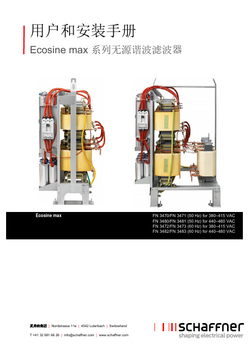
夏弗纳集团 | Nordstrasse 11e | 4542 Luterbach | Switzerland T +41 32 681 66 26 |******************| 用户和安装手册Ecosine max 系列无源谐波滤波器FN 3470/FN 3471 (50 Hz) for 380–415 VACFN 3480/FN 3481 (50 Hz) for 440–480 VACFN 3472/FN 3473 (60 Hz) for 380–415 VAC FN 3482/FN 3483 (60 Hz) for 440–480 VAC版权所有©2020 Schaffner International Ltd. 保留所有权利。
本用户手册和安装手册(“手册”)的所有权利,包括但不限于内容、信息和数字,均由夏弗纳国际有限公司(“夏弗纳”)独家拥有和保留。
本说明书仅适用于ecosine 滤波器的操作或使用。
未经夏弗纳事先书面许可,禁止对本手册的全部或部分进行任何处置、复制、传播、复制、修改、翻译、摘抄或使用。
鉴于夏弗纳将持续改进和开发产品,本手册中的信息可随时进行更改,而没有义务通知任何人此类修改或更改。
夏弗纳将尽一切可能的努力确保本手册的准确性和完整性。
夏弗纳否认任何形式的明示或隐含的保证、保证或承诺,包括但不限于手册的完整性、完整性、准确性、非侵权性、适销性或适用于某一特定目的。
1/68 2/68版本:02 (2020年10月)本文件(PDF 格式)的最新版本可以从您与夏弗纳组织的联系人处获取,也可以从 在线获得我们产品的其他技术文件也可以从网站 /downloads 的下载区域中找到文件名称:User and Installation Manual ecosine max Rev02.pdf适用于 ecosine 版本:FN 3470/FN 3471 (50 Hz) for 380–415 VAC FN 3480/FN 3481 (50 Hz) for 440–480 VAC FN 3472/FN 3473 (60 Hz) for 380–415 VAC FN 3482/FN 3483 (60 Hz) for 440–480 VAC版本历史版本日期描述01 2020年2月初版02 2020年10月整个文件的表格格式(从数据表粘贴为图片的表格被转换为真实可编辑的表格,以便于更好地翻译文件和未来可能的更新)纠正打字错误更好地统一文件内部和产品线之间的技术术语第3.1至3.4节绝缘等级SCH-155(F)规范已删除(文件错误),所有版本均使用绝缘等级SCH-200(N)第3.6.1节表20增加了AWG/kcmil中的横截面,并根据UL要求进行了更新增加了第3.6.2节,以满足陷波器断开跨接端子电缆要求增加第3.6.3节-辅助电缆要求增加第3.8节-热开关规范第3.9节表24参考柜零件的增加(第6至8行)第3.10节冷却的新要求,包括气流、进气口和机柜底部和背面适当开启要求的附加图片3/68 4/68i. Ecosine max 无源谐波滤波器Ecosine max 产品亮点夏弗纳 ecosine max 系列无源谐波滤波器是可配置的产品,可为3相非线性负载的电流谐波抑制的每个特定问题,提供定制的解决方案。
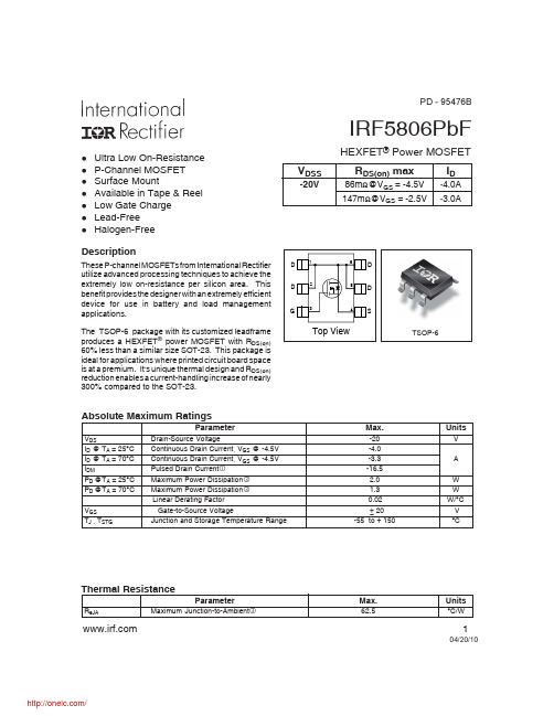
IRF5806TRPBF;中文规格书,Datasheet资料
-VDS , Drain-to-Source Voltage (V)
4
Fig 7. Typical Source-Drain Diode Forward Voltage
Fig 8. Maximum Safe Operating Area
10
ID = -4.0A
VDS =-16V
8
C,
Ciss
6
400
4
200
Coss Crss
1 10 100
2
0
0
-VDS , Drain-to-Source Voltage (V)
0
4
8
12
16
QG , Total Gate Charge (nC)
Fig 5. Typical Capacitance Vs. Drain-to-Source Voltage
Max.
-20 -4.0 -3.3 -16.5 2.0 1.3 0.02 ± 20 -55 to + 150
Units
V A W W W/°C V °C
Thermal Resistance
Parameter
RθJA Maximum Junction-to-Ambient
Max.
62.5
Units
°C/W
D D
1 6 2
A D
5
D
G
3
4
S
Top View
TSOP-6
Absolute Maximum Ratings
Parameter
VDS ID @ TA = 25°C ID @ TA = 70°C IDM PD @TA = 25°C PD @TA = 70°C VGS TJ , TSTG Drain-Source Voltage Continuous Drain Current, VGS @ -4.5V Continuous Drain Current, VGS @ -4.5V Pulsed Drain Current Maximum Power Dissipation Maximum Power Dissipation Linear Derating Factor Gate-to-Source Voltage Junction and Storage Temperature Range
艾特顿 198556 产品说明书

Eaton 198556Eaton Moeller® series Rapid Link - Speed controller, 4.3 A, 1.5 kW, Sensor input 4, 400/480 V AC, AS-Interface®, S-7.4 for 31 modules, HAN Q5General specificationsEaton Moeller® series Rapid Link Speed controller198556RASP5-4404A31-5120000S14015081964314157 mm 270 mm 220 mm 3.41 kgUL approval CE RoHSIEC/EN 61800-5-1 UL 61800-5-1Product NameCatalog NumberModel CodeEANProduct Length/Depth Product Height Product Width Product Weight Certifications Catalog Notes can be switched over from U/f to (vector) speed control Connection of supply voltage via adapter cable on round or flexible busbar junction Diagnostics and480 VIs the panel builder's responsibility. The specifications for the switchgear must be observed.480 V AC, 3-phase400 V AC, 3-phaseMeets the product standard's requirements.1.5 kW500 VMeets the product standard's requirements.-40 °C380 VInternal DC linkPC connectionKey switch position AUTOSelector switch (Positions: REV - OFF - FWD)Two sensor inputs through M12 sockets (max. 150 mA) for quick stop and interlocked manual operationThermo-click with safe isolationKey switch position OFF/RESETKey switch position HANDPTC thermistor monitoringFour fixed speedsIGBT inverterControl unit0 Hz200 %, IH, max. starting current (High Overload), For 2 seconds every 20 seconds, Power section Electromagnetic compatibility (EMC)Configuration to Rockwell PLC for Rapid LinkGeneration Change RA-SP to RASP5Generation change from RA-SP to RASP 4.0Connecting drives to generator suppliesGeneration change RAMO4 to RAMO5Generation change from RA-MO to RAMO 4.0Generation Change RASP4 to RASP5Rapid Link 5 - brochureDA-SW-drivesConnect - InstallationshilfeDA-SW-drivesConnect - installation helpDA-SW-USB Driver PC Cable DX-CBL-PC-1M5DA-SW-Driver DX-CBL-PC-3M0DA-SW-drivesConnect USB Driver DX-COM-PCKITDA-SW-USB Driver DX-COM-STICK3-KITDA-SW-drivesConnectMaterial handling applications - airports, warehouses and intra-logisticsProduct Range Catalog Drives EngineeringProduct Range Catalog Drives Engineering-ENDA-DC-00004184.pdfDA-DC-00004514.pdfDA-DC-00003964.pdfDA-DC-00004508.pdfeaton-bus-adapter-rapidlink-speed-controller-dimensions-003.eps eaton-bus-adapter-rapidlink-speed-controller-dimensions-002.eps eaton-bus-adapter-rapidlink-speed-controller-dimensions-004.eps eaton-bus-adapter-rapidlink-speed-controller-dimensions.epsETN.RASP5-4404A31-5120000S1.edzIL034085ZUMains voltage - max10.11 Short-circuit ratingRated operational voltage10.4 Clearances and creepage distancesOutput at quadratic load at rated output voltage - max Output voltage - max10.2.3.1 Verification of thermal stability of enclosures Ambient storage temperature - minMains voltage - minFitted with:Output frequency - minStarting current - max Application notes BrochuresCatalogs Certification reports DrawingseCAD model Installation instructions10 kA40 °CAS-Interface2 HP500 Hz8 kHz, 4 - 32 kHz adjustable, fPWM, Power section, Main circuitParameterization: drivesConnectDiagnostics and reset on device and via AS-Interface Parameterization: FieldbusParameterization: KeypadParameterization: drivesConnect mobile (App)-10 °C≤ 0.6 A (max. 6 A for 120 ms), Actuator for external motor brakeDoes not apply, since the entire switchgear needs to be evaluated.4.3 ADoes not apply, since the entire switchgear needs to be evaluated.Does not apply, since the entire switchgear needs to be evaluated.Speed controller Rapid Link 5MN034004EN MZ040046_EN MN040003_ENramo5_v19.dwg rasp5_v19.stpRated conditional short-circuit current (Iq)Ambient operating temperature - maxCommunication interfaceAssigned motor power at 115/120 V, 60 Hz, 1-phase Output frequency - maxSwitching frequencyFeaturesAmbient operating temperature - minBraking currentNumber of HW-interfaces (serial TTY)10.6 Incorporation of switching devices and components Nominal output current I2N10.2.6 Mechanical impact10.3 Degree of protection of assembliesProduct categoryRadio interference class Installation videos Manuals and user guidesmCAD modelC1: for conducted emissions onlyC2, C3: depending on the motor cable length, the connected load, and ambient conditions. External radio interference suppression filters (optional) may be necessary.Heat dissipation capacity Pdiss0 WRated control voltage (Uc)24 V DC (-15 %/+20 %, external via AS-Interface® plug) 400/480 V AC (external brake 50/60 Hz)Assigned motor power at 460/480 V, 60 Hz, 3-phase2 HPNumber of HW-interfaces (RS-422)Mains current distortion120 %ProtocolAS-Interface profile cable: S-7.4 for 31 modulesASI10.9.2 Power-frequency electric strengthIs the panel builder's responsibility.Overvoltage categoryIIIDegree of protectionIP65NEMA 12Ambient storage temperature - max70 °CRated impulse withstand voltage (Uimp)2000 VConnectionPlug type: HAN Q5Overload currentFor 60 s every 600 sAt 40 °CFunctionsFor actuation of motors with mechanical brakeOutput at linear load at rated output voltage - max1.5 kWMains voltage tolerance380 - 480 V (-10 %/+10 %, at 50/60 Hz)Leakage current at ground IPE - max3.5 mAConverter typeU converter10.2.2 Corrosion resistanceMeets the product standard's requirements.Supply frequency50/60 Hz10.2.4 Resistance to ultra-violet (UV) radiationMeets the product standard's requirements.10.2.7 InscriptionsMeets the product standard's requirements.Shock resistance15 g, Mechanical, According to IEC/EN 60068-2-27, 11 ms, Half-sinusoidal shock 11 ms, 1000 shocks per shaftApplication in domestic and commercial area permittedYesNumber of inputs (analog)Number of phases (output)310.12 Electromagnetic compatibilityIs the panel builder's responsibility. The specifications for the switchgear must be observed.10.2.5 LiftingDoes not apply, since the entire switchgear needs to be evaluated.Number of HW-interfaces (RS-485)1Number of HW-interfaces (industrial ethernet)Efficiency98 % (η)System configuration typeCenter-point earthed star network (TN-S network)AC voltagePhase-earthed AC supply systems are not permitted.10.8 Connections for external conductorsIs the panel builder's responsibility.ProtectionFinger and back-of-hand proof, Protection against direct contact (BGV A3, VBG4)Braking voltage400/480 V AC -15 % / +10 %, Actuator for external motor brakeApplication in industrial area permittedYesClimatic proofing< 95 %, no condensationIn accordance with IEC/EN 5017810.9.3 Impulse withstand voltageIs the panel builder's responsibility.Overload current IL at 150% overload6.5 AInput current ILN at 150% overload4.1 ANumber of HW-interfaces (RS-232)Number of inputs (digital)4Current limitationAdjustable, motor, main circuit0.4 - 4.3 A, motor, main circuitCable lengthC2 ≤ 5 m, maximum motor cable lengthC1 ≤ 1 m, maximum motor cable lengthC3 ≤ 25 m, maximum motor cable length10.5 Protection against electric shockDoes not apply, since the entire switchgear needs to be evaluated.Mounting positionVerticalMains switch-on frequencyMaximum of one time every 60 seconds10.13 Mechanical functionThe device meets the requirements, provided the information in the instruction leaflet (IL) is observed.10.9.4 Testing of enclosures made of insulating materialIs the panel builder's responsibility.Heat dissipation per pole, current-dependent Pvid0 WElectromagnetic compatibility1st and 2nd environments (according to EN 61800-3)Resolution0.1 Hz (Frequency resolution, setpoint value)Assigned motor power at 460/480 V, 60 Hz2 HPRelative symmetric net voltage tolerance10 %Rated operational current (Ie)4.3 A at 150% overload (at an operating frequency of 8 kHz and an ambient air temperature of +40 °C)Number of outputs (analog)Rated operational power at 380/400 V, 50 Hz, 3-phase1.5 kWNumber of HW-interfaces (USB)Operating modeU/f controlBLDC motorsSensorless vector control (SLV)Synchronous reluctance motorsPM and LSPM motorsRated frequency - min45 HzDelay time< 10 ms, Off-delay< 10 ms, On-delayNumber of outputs (digital)Power consumption46 W10.2.3.2 Verification of resistance of insulating materials to normal heatMeets the product standard's requirements.10.2.3.3 Resist. of insul. mat. to abnormal heat/fire by internal elect. effectsMeets the product standard's requirements.Number of HW-interfaces (other)1Rated frequency - max66 HzVibrationResistance: According to IEC/EN 60068-2-6Resistance: 57 Hz, Amplitude transition frequency on accelerationResistance: 10 - 150 Hz, Oscillation frequencyResistance: 6 Hz, Amplitude 0.15 mmShort-circuit protection (external output circuits)Type 1 coordination via the power bus' feeder unit, Main circuit10.7 Internal electrical circuits and connectionsIs the panel builder's responsibility.Braking torque≤ 30 % (I/Ie)Adjustable to 100 % (I/Ie), DC - Main circuitRelative symmetric net frequency tolerance10 %10.10 Temperature riseThe panel builder is responsible for the temperature rise calculation. Eaton will provide heat dissipation data for the devices.Number of HW-interfaces (parallel)Assigned motor power at 230/240 V, 60 Hz, 1-phase2 HPInterfacesMax. total power consumption from AS-Interface® power supply unit (30 V): 190 mANumber of slave addresses: 31 (AS-Interface®) Specification: S-7.4 (AS-Interface®)Number of phases (input)3Eaton Corporation plc Eaton House30 Pembroke Road Dublin 4, Ireland © 2023 Eaton. All Rights Reserved. Eaton is a registered trademark.All other trademarks areproperty of their respectiveowners./socialmedia32.3 W at 25% current and 0% speed 33.2 W at 25% current and 50% speed 35.2 W at 50% current and 90% speed 36.2 W at 50% current and 0% speed 37.6 W at 50% current and 50% speed 46.3 W at 100% current and 90% speed 48.7 W at 100% current and 0% speed 48.7 W at 100% current and 50% speed 0Max. 2000 mAbove 1000 m with 1 % performance reduction per 100 mHeat dissipation at current/speed Number of interfaces (PROFINET)Altitude。
洛美E 2当地电流分离器和信号分离器SIL3 SIL2,HART透明度说明书
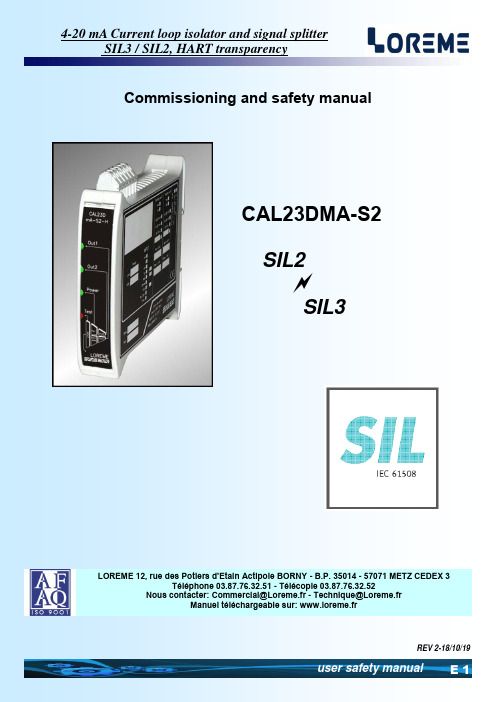
E 1user safety manualLOREME 12, rue des Potiers d'Etain Actipole BORNY - B.P. 35014 - 57071 METZ CEDEX 3Téléphone 03.87.76.32.51 - Télécopie 03.87.76.32.52Nouscontacter:******************************@Loreme.frManuel téléchargeable sur: www.loreme.frREV 2-18/10/19CAL23DMA-S2SIL2 SIL3Commissioning and safety manual4-20 mA Current loop isolator and signal splitterSIL3 / SIL2, HART transparencySommaire1 Introduction E3 1.1 General Information E3 1.2 Functions and intended uses E3 1.3 Standards and Guidelines E32 Safety function and safety state E4 2.1 Safety function E4 2.2 Safety fallback position E43 Safety Recommendation E4 3.1 Interfaces E4 3.2 Configuration / Calibration E4 3.3 Useful lifetime E44 Installation, commissioning and replacement E5 4.1 Front panel description E5 4.2 Electrical connection E6 4.3 Wiring E65 Commissioning and periodic proof E7 5.1 control steps E7 5.2 proof interval E7Annex 1: EMC consideration E8 Annex 2 : terms et definitions.E9 E 2LOREME 12, rue des Potiers d'Etain - 57071 Metz 03.87.76.32.51-Fax03.87.76.32.52-Email:******************************@Loreme.frSOMMAIRE4-20 mA Current loop isolator and signal splitterSIL3 / SIL2, HART transparency1 Introduction1.1 General InformationThis manual contains necessary information for product integration to ensure the functional safety of related loops.All the failure modes and the HFT of the module are specified in the FMEA analysis referenced AMDEC_CAL23DmA Revision A1Other documents:Technical datasheet CAL23DmA- EMC conformity declaration CAL23DmA- FMEA analysis CAL23DmAThe mentioned documents are available on www.loreme.frThe assembly, installation, commissioning and maintenance can only be performed by trained personnelqualified and have read and understood the instructions in this manual.When it is not possible to correct the defects, the equipment must be decommissioned, precaution must be taken to pro-tect against accidental use. Only the manufacturer can bring the product to be repaired.Failure to follow advice given in this manual can cause a deterioration in security features, and damage to property, en-vironment or people.1.2 Functions and intended usesThe transducer CAL23DmA-S2 provides isolation and duplication of analog current loop 4 ....20mAIt also allows the transmission of HART signals between input and output 1.an auxiliary power supply for a loop powered sensor is available.The devices are designed, manufactured and tested according to security rules.They should be used only for the purposes described and in compliance with environmental conditionscontained in the data sheet: http://www.loreme.fr/fichtech/CAL23DmA_eng.pdf1.3 Standards and GuidelinesThe devices are evaluated according to the standards listed below:• Functional safety according to IEC 61508, 2000 edition:Standard for functional safety of electrical / electronic / programmable electronic .The evaluation of the material was performed by "failure modes and effects analysis"(IEC 60812 - Issue 2 - 2006)to determine the device safe failure fraction (SFF)The FMEA is based on (IEC 62380-2004)Reliability data handbook. Universal model for reliability prediction of electronics components, PCBs and equipment1.4 Manufacturer informationLOREME SAS12, rue des potiers d'étain 57071 Actipole Metz Bornywww.loreme.frE 3SOMMAIRE4-20 mA Current loop isolator and signal splitterSIL3 / SIL2, HART transparency2 Safety function and safety state2.1 Safety functionThe safety function of the device is completed, as long as the outputs reproduce the input current(4 ... 20 mA) with a tolerance of + / -2%.The operation range of the output signal goes from 3.8 mA to 20.5 mA2.2 Safety fallback positionThe safety fallback state is defined by output current outside the range of 3.6 mA to 21mA.• Either an output current <3.6 mA• Either an output current> 21 mAThe application should always be configured to detect the current value out of range(<3.6 mA -> 21 mA) and considered "faulty ".Thus, in the FMEA study, this condition is not considered dangerous.The reaction time for all safety functions is <30 ms.3 Safety Recommendation3.1 InterfacesThe device has the following interfaces.• safety interfaces: input, output 1, output 2, simulation link (at rear the front panel)• not safety interfaces : noHART communication is not relevant for functional safety3.2 Configuration / Calibrationno hardware configuration is needed, the calibration is only possible by factory return .no changes should be made to the device3.3 Useful lifetimeAlthough a constant failure rate is assumed by the probabilistic estimation,that it applies only to the useful lifetime of components.Beyond this lifetime, the probability of failure is increasing significantly with time.The useful lifetime is very dependent components themselvesand operating conditions such as temperature, particularly(Electrolytic capacitors are very sensitive to temperature).This assumption of a constant failure rate is based on the bathtub curve,which shows the typical behavior of electronic components.Therefore, the validity of this calculation is limited to the useful life of each component.It is assumed that early failures are detected for a very high percentage during the burn inand the installation period, assuming a constant failure rate during the useful life remains valid.according to IEC 61508-2, a useful lifetime based on the feedback, must be considered.Experience has shown that the useful lifetime is between 15 and 20 years, and may be higherif there are no components with reduced lifetime in security function.(Such as electrolytic capacitors, relays, flash memory, opto coupler)and if the ambient temperature is well below 60 °C.Note:The useful lifetime corresponds to constant random failure rate of the device.The effective lifetime may be higher.user must ensure that the device is no longer necessary for the security before its disposal.E 4LOREME 12, rue des Potiers d'Etain - 57071 Metz ☎03.87.76.32.51-Fax03.87.76.32.52-Email:******************************@Loreme.frSOMMAIRE4-20 mA Current loop isolator and signal splitterSIL3 / SIL2, HART transparency4 Installation, commissioning and replacementOperating capacity and current error reporting should be checkedduring commissioning (validation) see section: "commissioning and periodic proof"and at appropriate intervals recommended in paragraph: " proof interval "Any device that does not satisfy the commissioning control must be replaced.WARNING!No user maintenance should be conducted, a defective device must be replaced by a new device of the same type.For a repair return or recalibration, it is very important that all types of equipment failures are reportedto allow the company to take corrective action to prevent systematic errors.4.1 Front panel descriptionConvention:- The green LED indicate correct operation.- Red LED indicate a warning or a defect.Output 1 current passes through the Green led andindicates that the output loop is closed. (Current flow)the green LED goes OFF when opening the output loopand when using test terminals located under the frontpanelOutput 2 current passes through the Green led andindicates that the output loop is closed. (Current flow)the green LED goes OFF when opening the output loopand when using test terminals located under the frontpanelGreen power supply LED indicates that the device isproperly powered.flashes when the power goes into protection.(under voltage , thermal overload or short circuit )Red "test" LEDindicates that the module is in simulation mode.(Insertion of the jack underneath the front face)the device transmits input current injected on the simu-lation cable.(The led goes off when the simulation link is removedand the device return in normal operation)Jack socket (simulation link) located under the frontpanel allows the switching in test mode for the periodicloop control.(Use only the cable provided by LOREMEfor this purpose)E 5SOMMAIRE4-20 mA Current loop isolator and signal splitterSIL3 / SIL2, HART transparency4.2 Electrical connection* Device power supply :between terminal K + and terminal L - , The module is insensitive to power polarityThe polarity is given as a guide for the implementation of schemes.* Output 1: Two modes of operation are possible (active mode and loop powered mode)- Active Mode (device supplied the output current) between terminal G + and terminal H -- Loop powered mode (the device regulates the current of a loop with his own power supply) between terminal H + and terminal J - (Loop powered output is protected against reverse polarity)(Hart protocol transparency is ensured between the input and output 1)* Output 2: Two modes of operation are possible (active mode and loop powered mode)- Active Mode (device supplied the output current) between terminal P + and terminal Q -- Loop powered mode (the device regulates the current of a loop with his own power supply) between terminal Q+ and terminal O - (Loop powered output is protected against reverse polarity)WARNING !Do not wire loop with its own power supply on the active output otherwise the device can be damaged .Do not exceed the technical specifications to ensure output safe operation.- In Loop powered mode , the output loop voltage must be between 10 volts and 35 volts- In Active mode, the output load resistance must be between 0 ohms and 750 ohms.Input : two modes of operation are possible (active mode and passive mode)- passive input (the sensor must provide the device input current) Terminal D+ and Terminal E-- active input (the device provides power supply to the input loop powered sensor) Terminal C (+22 V) and Terminal D - WARNING !- Do not short the sensor power supply (terminal C) otherwise the device can be damaged- During a input simulation on the test jack (red LED 'test' on) the safety function of the unit is not maintained,(the unit does not repeat the signal from the input terminal, but the signal injected into the test lead.4.3 WiringE 6LOREME 12, rue des Potiers d'Etain - 57071 Metz ☎03.87.76.32.51-Fax03.87.76.32.52-Email:******************************@Loreme.frSOMMAIRE4-20 mA Current loop isolator and signal splitterSIL3 / SIL2, HART transparency5 Commissioning and periodic proofThe periodic test procedure is defined by LOREMEand must be followed by the end user to ensure and guarantee the SIL level over time.Periodic testing should be performed following the procedure defined belowand at the intervals defined under paragraph " proof interval "5.1 control stepsPeriodic proof allows detection of possible product internal failure and loop calibration.environmental conditions and a minimum heating time of 5 minutes must be respected.Isolator test and complete output Loop control (the system is unavailable during the test)1. If necessary, bypass the security system and / or take appropriate provision to ensure safety during the test.2. raise the front hood off the device3. Using the jack cable and a simulator (current generator * Note 1) set the input current to high alarm value (≥ 21.0 mA).(The insertion of the jack must turn on the red LED "test")4. Check if the current of each output reaches this value at +/-2%5. Set the input current to the low alarm value (≤ 3.6 mA)6. Check if the signal from each output reaches this value at +/-2%7. Set the output current to a median value (= 12 mA)8. Check if the signal from each output reaches this value at +/-2% (linearity check and the transfer function)9. Remove the simulation link (red LED goes OFF "test"), close the front panel hood.10. Remove the bypass on the safety controller system or return to a normal operating condition11. After testing, the results should be documented and archived.Any device that does not satisfy the control needs to be replaced.Note 1: The current generator must be calibrated (according to the state of the art and practice)5.2 proof intervalAccording table 2 from CEI 61508-1 the PFDavg ,for systems operating in low demand mode,must be between ≥ 10-3 and <10-2for SIL2 safety functions and between ≥ 10-4 and <10-3 for SIL3 safety functions .λsafeλdangerous = PFH SFF305 FIT 1.8 FIT 99.4%temperature conditions 45°CPFD avg value depending proof intervalT[Proof] = 1 an T[Proof] = 5 ans T[Proof] = 10 ans T[Proof] = 20 ans PFD avg=7.88E-06PFD avg=3.94E-05PFD avg=7.88E-05PFD avg=1.57E-04approximation : PFDavg = λdangerous x T[Proof] /2 (error caused by approximation < 3%)Fields marked in green means that the calculated values of PFDavg are within the limits allowed for SIL 3Summary:fault probability PFD = 7.88 E-6 x Tproof [year]either for : Tproof = 10 years 8 % from SIF and for Tproof = 20 years 16 % from SIF in SIL3Remarks :- Test intervals should be determined according to the PFDavg required .- The SFF , PFDavg and PFH must be determined for the entire safety instrumented function (SIF)ensuring that the " out of range current values" are detected at system leveland they actually lead to the safety position.E 7SOMMAIRE4-20 mA Current loop isolator and signal splitterSIL3 / SIL2, HART transparencyAnnex 1: EMC consideration1) Introduction:In order to satisfy its policy of Electromagnetic compatibility, based on the EU Directive 89/336/EC,LOREME company takes into account the standards relative to this directive early in the design of each product.All tests performed on devices designed to work in industrial environment, are compliant to EN 50081-2 and EN 50082-2 in order to establish the EMC compliance certificate. The devices being in some typical configurations during the test, it is impossible to guarantee results in all possible configurations.To ensure optimum operation of each device ,it would be judicious to comply with several recommendations of use.2) Recommendations:2.1) General information:- Comply with the mounting recommendations (mounting direction, devices spacing ...) specified in the datasheet.- Follow the recommendations of use (temperature range, protection) specified in the datasheet.- Avoid dust and excessive moisture, corrosive gases, sources of heat.- Avoid disturbed environments and disruptive phenomena.- If possible, group together the instrumentation devices in a zone separated from the power and relay circuits.- Avoid close proximity with remote switches for high power, contactors, relays, SCR ,...- Do not approach within two feet of a device with a walkie-talkie ( 5 W output power),because it creates a electromagnetic field with an intensity greater than 10 V / M for a distance of less than 50 cm.2.2 ) Power supply:- Observe the characteristics specified in the datasheet (Voltage and frequency tolerance).- It is preferable that the power comes from a system with section switches equipped with fuses forinstrumentation components, and the supply line is the most direct route possible from the section switch.Avoid using this power supply to control relays, contactors, solenoid valves, …- If the power circuit is heavily disturbed by SCR switching , motor, inverter, ...it may be necessary to install an isolation transformer specifically for instrumentationand connecting the screen to ground.- It is also important that the installation has a good grounding, and preferable that the voltagecompared to neutral does not exceed 1V, and the ground resistance less than 6 ohms.- If the installation is located near high frequency generators or arc welding, itis preferable to mount adequate power line filter.2.3) Inputs / Outputs:- In harsh conditions, it is advisable to use sheathed twisted cables whose ground braid will be grounded at on point.- It is advisable to separate the input/output lines from the power supply lines in order to avoid the coupling phenomena. - It is also advisable to minimize the lengths of data cables.E 8LOREME 12, rue des Potiers d'Etain - 57071 Metz ☎03.87.76.32.51-Fax03.87.76.32.52-Email:******************************@Loreme.frSOMMAIRE4-20 mA Current loop isolator and signal splitterSIL3 / SIL2, HART transparencyCertification to a Safety Integrity LevelThe International Electrotechnical Commission's (IEC) standard IEC 61508, defines SIL using requirements grouped into two broad categories: hardware safety integrity and systematic safety integrity.A device or system must meet the requirements for both categories to achieve a given SIL.The SIL requirements for hardware safety integrity are based on a probabilistic analysis of the device. To achieve a given SIL, the device must meet targets for the maximum probability of dangerous failure and a minimum Safe Failure Fraction. The concept of'dangerous failure' must be rigorously defined for the system in question, normally in the form of requirement constraints whose integ-rity is verified throughout system development. The actual targets required vary depending on the likelihood of a demand, the com-plexity of the device(s), and types of redundancy used.PFD (Probability of Failure on Demand) and RRF (Risk Reduction Factor) of low demand operation for different SILs as defined in IEC EN 61508 are as follows:For continuous operation, these change to the following.Hazards of a control system must be identified then analyzed through risk analysis. Mitigation of these risks continues until their over-all contribution to the hazard are considered acceptable. The tolerable level of these risks is specified as a safety requirement in the form of a target 'probability of a dangerous failure' in a given period of time, stated as a discrete SIL level.Abbreviation DescriptionHFT Hardware Fault Tolerance, capability of a functional unit to continue the execution of the demanded function when faults or anomalies exist.MTBF Mean interval between two failuresMTTR Mean interval between the occurrence of the failure in a device or system and its repairPFD Likelihood of dangerous safety function failures occurring on demandPFDavg Average likelihood of dangerous safety function failures occurring on demandSIL Safety Integrity Level, the international standard IEC 61508 defines four discrete safety integrity levels (SIL1 to SIL4).Each level corresponds to a specific probability range with respect to the failure of a safety function.The higher the integrity level of the safety-related system,the lower the likelihood of the demanded safety functions not occurring.SFF Safe Failure Fraction, the proportion of failures without the potential to put the safety-related system intoa dangerous or impermissible functional state.TProof In accordance with IEC 61508-4, chapter 3.5.8,TProof is defined as the periodic testing to expose errors in a safety-related system.XooY Classification and description of the safety-related system with respect to redundancyand the selection procedure used. "Y" indicates how often the safety function is carried out (redundancy)."X" determines how many channels must work properly.λsd und λsu λsd Safe detected + λsu Safe undetected Safe failure (IEC 61508-4, chapter 3.6.8):A safe failure is present when the measuring system switches to the defined safe stateor the fault signaling mode without the process demanding it.λdd +λdu λdd Dangerous detected + λdu Dangerous undetected Unsafe failure (IEC 61508-4, chapter 3.6.7):Generally a dangerous failure occurs if the measuring systemswitches into a dangerous or functionally inoperable condition.λdu λdu Dangerous undetected A dangerous undetected failure occurs if the measuring system does not switch into a safeE 9。
台湾制造DUAL INPUT RTD 四位数数字温度计说明书

MADE IN TAIWANOPERATING INSTRUCTIONSHH804UDUAL INPUT RTD THERMOMETERINTRODUCTION This instrument is a 4_digit,compact-sized portable digital thermometer designed to use external 100_Platinum RTD as temperature sensor.Tem-perature indication follows Reference Temperature/Resistance Tables (Pt385for European Curve,Alpha=.00385.Pt3926for American Curve,Al pha=.003926. Pt3916 for Japan Curve, Alpha=.003916.)SAFETY INFORMATIONIt is recommended that you read the safety and operation instructions before using the thermometer.WARNINGTo avoid electrical shock, do not use this instrument when working voltagesat the measurement surface over 24V AC or DC.WARNINGTo avoid damage or burns, do not take temperature measurements in micro-wave ovens.ENVIRONMENTALAmbient Operating Ranges:0°C to 50°C (32°F to 122°F) <70% R.H.Storage Temperature:-20°C to 60°C (-4°F to 140°F) <80% R.H.GENERALDisplay:4_ digit liquid crystal display (LCD) with maximum reading of 19999Overload:“----.-“ or “OL” is display.Battery:1.5V x 4 PCS (SIZE AAA) R03P.Battery Life:200 hours typical with carbon zinc battery Auto power off: 30 minutes Dimensions:160mm(H) x83mm(W) x 38mm(D)Weight:Approx. 255g including batteries.SPECIFICATIONSELECTRICALTemperature Scale: Celsius or Fahrenheit user-selectable Measurement Range:Pt385(100_) -200°C to 800°C, (-328°F to 1472°F)Pt3916/Pt3926(100_) -200°C to 630°C, (-328°F to 1166°F)Resolution:0.1°C or 0.2°F Accuracy:Accuracy is specified for operating temperatures over the range of 18°C to 28°C (64°F to 82°F), for 1 year, not including RTD probe error.±(0.05% rdg + 0.2°C) on °C scale ±(0.05% rdg + 0.4°F) on °F scale Temperature Coefficient:0.1 times the applicable accuracy specification per °C from 0°C to 18°C and 28°C to 50°C (32°F to 64°F and 82°F to 122°F).Input Protection:24V dc or 24V ac rms maximum input voltage on any combination of input pins.Maximum Differential Common Mode Voltage (Maximum Voltage be-tween T1 and T2 during measurement): 1volt.Reading Rate: 1sample/second.Input Connector:Accepts 4 pin mini-DIN connectors.OPERATING INSTRUCTIONS1.Power ButtonThebutton turns the thermometer on or off. In the SET mode the unit cannot be powered off. Exit the SET mode to power off.APO function modePress “”power button for more than 6seconds to disable auto power function. The display will show “APO OFF”.2.°C/°F Selecting the Temperature Scale (Main display)Readings are displayed in either degrees Celsius(°C) or degrees Fahren-heit(°F). When the thermometer is turned on, it is set to the temperature scale that was in use when the thermometer was last turned off. To change the temperature scale, press the °C/°F key.3. “ ” Display Back-LightPress the “ ” key to turn on or turn off the back light.4. T1 T2/T1-T2 Main display Input SelectionThe input selection button determines which input is shown on the display;T1,T2or the difference between the two probes (T1-T2).When thermometer is turned on, it is set to T1.5. TYPE(Pt385/Pt3926/Pt3916) Input RTD Probe Select (Main display)The TYPE button selects the RTD curve to use for the input currently shown.When the thermometer is turned on,it is set to the curve that selected when the thermometer was last turned off.6. MIN MAX with Time record Mode (only Main display)Press MIN MAX key to enter the MIN MAX Recording mode,(displays Maximum reading with time,Minimum reading with time and Average reading stored in recording mode).In the this mode the automatic power-off feature is disabledand key,°C/°F key,REL key,SET key,Hi/Lo Li key and main display T1T2T1-T2key,TYPE key are disabled.beeper emits a tone when a new minimum or maximum value is recorded.Push MIN MAX key to cycle through the MAX, MIN and AVG readings.If an overload is recorded,the averaging function is Stopped.In the mode,press HOLD key to stop the recording of readings,all values are zen,press again to restart recording.To prevent accidental loss of MAX and AVG data,in this mode can only be cancelled by pressing hold down the MIN MAX key for 2seconds to exit and erased recorded readings.7. REL Relative mode (only Main display)Press REL key to enter the Relative mode,zero the display,and store displayed Reading as a reference value and annunciator REL is displayed.Press REL key again to exit the relative mode.The relative value can be entered by the user.(See “SET mode”later in this manual.)When the sired Relative value has been entered,press REL key to enter the Relative mode,press SET key use set Relative value as a reference value.Press key again to exit the relative mode.In the Relative mode,the value (can >±1999.9counts)shown on the LCD is always the difference between stored reference and the present reading.8.HOLD Mode (only Main display)Press the HOLD key to enter the Data Hold mode,the “HOLD”annunciator is displayed.When HOLD mode is selected,the thermometer held the sent readings and stops all further measurements.Press the HOLD again to cancel HOLD mode causing thermometer to resume taking ureents.In the MIN/MAX recording mode,press HOLD key to stop the cording.Press HOLD key again to resume recording.(Previously recorded read are not erased).9. SET mode (Relative value set, Time set and Hi/Lo Limits value set)Press SET key to enter Relative values SET mode (Press ENTER key escape relative values set mode),REL set mode.====.=is displayed main display.Relative value is entered via overlay numbers,thenHH804UOMEGAnet ®On-Line ServiceInternet e-mail **************Czech Republic:Frystatska 184, 733 01 Karvina ´, Czech Republic Tel: +420 (0)59 6311899FAX: +420 (0)59 6311114Toll Free: 0800-1-66342e-mail:*****************Germany/Austria:Daimlerstrasse 26, D-75392 Deckenpfronn, Germany Tel: +49 (0)7056 9398-0 FAX: +49 (0)7056 9398-29TollFreeinGermany************e-mail:*************Servicing Europe:U.S.A. and Canada:Sales Service: 1-800-826-6342/1-800-TC-OMEGA Customer Service: 1-800-622-2378/1-800-622-BEST Engineering Service: 1-800-872-9436/1-800-USA-WHEN U.S.A.: ISO 9001 Certified One Omega Drive, Box 4047Stamford, CT 06907-0047Tel: (203) 359-1660FAX: (203) 359-7700e-mail:**************Servicing North America:For immediate technical or application assistance:Mexico:En Espan~ol: (001) 203-359-7803FAX: (001) 203-359-7807e-mail:*******************************.mxUnited Kingdom ISO 9002 Certified One Omega DriveRiver Bend Technology Centre Northbank, Irlam Manchester M44 5BD United KingdomTel: +44 (0)161 777 6611 FAX: +44 (0)161 777 6622Toll Free in United Kingdom: 0800-488-488e-mail:**************.ukCanada:976 BergarLaval (Quebec) H7L 5A1, Canada Tel: (514) 856-6928FAX: (514) 856-6886e-mail:*************Where Do I Find Everything I Need for Process Measurement and Control?OMEGA…Of Course!Shop online at M4501/0607TEMPERATUREⅪߜThermocouple, RTD & ThermistorProbes, Connectors, Panels &Assemblies ⅪߜWire: Thermocouple, RTD &Thermistor ⅪߜCalibrators & Ice Point References ⅪߜRecorders, Controllers & ProcessMonitors ⅪߜInfrared PyrometersPRESSURE, STRAIN AND FORCEⅪߜTransducers & Strain GagesⅪߜLoad Cells & Pressure Gages ⅪߜDisplacement Transducers ⅪߜInstrumentation & AccessoriesFLOW/LEVELⅪߜRotameters, Gas Mass Flowmeters &Flow Computers ⅪߜAir Velocity Indicators ⅪߜTurbine/Paddlewheel Systems ⅪߜTotalizers & Batch ControllerspH/CONDUCTIVITYⅪߜpH Electrodes, Testers & Accessories ⅪߜBenchtop/Laboratory Meters ⅪߜControllers, Calibrators, Simulators &Pumps ⅪߜIndustrial pH & ConductivityEquipmentDATA ACQUISITIONⅪߜData Acquisition & EngineeringSoftware ⅪߜCommunications-Based AcquisitionSystems ⅪߜPlug-in Cards for Apple, IBM &Compatibles ⅪߜDatalogging Systems ⅪߜRecorders, Printers & PlottersHEATERSⅪߜHeating CableⅪߜCartridge & Strip Heaters ⅪߜImmersion & Band Heaters ⅪߜFlexible Heaters ⅪߜLaboratory HeatersENVIRONMENTALMONITORING AND CONTROLⅪߜMetering & Control InstrumentationⅪߜRefractometers ⅪߜPumps & TubingⅪߜAir, Soil & Water Monitors ⅪߜIndustrial Water & Wastewater Treatment ⅪߜpH, Conductivity & Dissolved OxygenInstrumentsRETURN REQUESTS/INQUIRIESDirect all warranty and repair requests/inquiries to the OMEGA Customer Service Department.BEFORE RETURNING ANY PRODUCT(S) TO OMEGA, PURCHASER MUST OBTAIN AN AUTHORIZED RETURN (AR) NUMBER FROM OMEGA’S CUSTOMER SERV ICE DEPARTMENT (IN ORDER TO AV OID PROCESSING DELAYS). The assigned AR number should then be marked on the outside of the return package and on any correspondence.The purchaser is responsible for shipping charges, freight, insurance and proper packaging to prevent breakage in transit.FOR WARRANTY RETURNS, please have the following information available BEFORE contacting OMEGA:1.Purchase Order number under which the product was PURCHASED,2.Model and serial number of the product under warranty, and3.Repair instructions and/or specific problems relative to the product.FOR NON-WARRANTY REPAIRS,consult OMEGA for current repair charges. Have the following information available BEFORE contacting OMEGA:1. Purchase Order number to cover the COST of the repair,2.Model and serial number of the product, and3.Repair instructions and/or specific problems relative to the product.WARRANTY/DISCLAIMEROMEGA ENGINEERING, INC. warrants this unit to be free of defects in materials and workmanship for a period of 13 months from date of purchase. OMEGA’s WARRANTY adds an additional one (1) month grace period to the normal one (1) year product warranty to cover handling and shipping time. This ensures that OMEGA’s customers receive maximum coverage on each product.If the unit malfunctions, it must be returned to the factory for evaluation. OMEGA’s Customer Service Department will issue an Authorized Return (AR) number immediately upon phone or written request. Upon examination by OMEGA, if the unit is found to be defective, it will be repaired or replaced at no charge. OMEGA’s WARRANTY does not apply to defects resulting from any action of the purchaser, including but not limited to mishandling,improper interfacing, operation outside of design limits, improper repair, or unauthorized modification. This WARRANTY is VOID if the unit shows evidence of having been tampered with or shows evidence of having been damaged as a result of excessive corrosion; or current, heat, moisture or vibration; improper specification; misapplication; misuse or other operating conditions outside of OMEGA’s control. Components in which wear is not warranted, include but are not limited to contact points, fuses, and triacs.OMEGA is pleased to offer suggestions on the use of its various products.However, OMEGA neither assumes responsibility for any omissions or errors nor assumes liability for any damages that result from the use of its products in accordance with information provided by OMEGA, either verbal or written.OMEGA warrants only that the parts manufactured by the company will be as specified and free of defects. OMEGA MAKES NO OTHER W ARRANTIES OR REPRESENTATIONS OF ANY KIND W HATSOEVER, EXPRESSED OR IMPLIED,EXCEPT THAT OF TITLE, AND ALL IMPLIED W ARRANTIES INCLUDING ANY WARRANTY OF MERCHANTABILITY AND FITNESS FOR A PARTICULAR PURPOSE ARE HEREBY DISCLAIMED. LIMITATION OF LIABILITY: The remedies of purchaser set forth herein are exclusive, and the total liability of OMEGA with respect to this order, whether based on contract, warranty, negligence, indemnification, strict liability or otherwise, shall not exceed the purchase price of the component upon which liability is based. In no event shall OMEGA be liable for consequential,incidental or special damages.CONDITIONS: Equipment sold by OMEGA is not intended to be used, nor shall it be used: (1)as a “Basic Component” under 10 CFR 21 (NRC), used in or with any nuclear installation or activity; or (2) in medical applications or used on humans. Should any Product(s) be used in or with any nuclear installation or activity, medical application, used on humans, or misused in any way, OMEGA assumes no responsibility as set forth in our basic WARRANTY /DISCLAIMER language, and, additionally, purchaser will indemnify OMEGA and hold OMEGA harmless from any liability or damage whatsoever arising out of the use of the Product(s) in such a manner.he policy of OMEGA Engineering, Inc. to comply with all worldwide safety and EMC/EMI ations that apply. OMEGA is constantly pursuing certification of its products to thepean New Approach Directives. OMEGA will add the CE mark to every appropriate device certification.nformation contained in this document is believed to be correct, but OMEGA accepts no ty for any errors it contains, and reserves the right to alter specifications without notice.NING: These products are not designed for use in, and should not be used for, human cations.OMEGAʼs policy is to make running changes, not model changes, whenever an improvement is possible. This affords our customers the latest in technology and engineering.OMEGA is a registered trademark of OMEGA ENGINEERING, INC.© Copyright 2007 OMEGA ENGINEERING, INC. All rights reserved. This document may not be copied, photocopied, reproduced, translated, or reduced to any electronic medium or machine-readable form, in whole or in part, without the prior written consent of OMEGA ENGINEERING, INC.overlay ENTER key, stored the relative value, enter Time set mode.Time set mode,(Press ENTER key can escape Time set mode)=.===:==is displayed in second and third display.Time (hours,minutes,seconds)value is entered via overlay numbers,then press overlay ENTER key.Time start from set time value, enter Hi/Lo Limits value set mode.Hi Limit value set mode,(Press ENTER key can escape Hi Limit value set mode),====.=is displayed in main display,Hi Limit value is entered via overlay numbers,then press overlay ENTER key,stored the Hi Limit value,enter Lo Limit value set mode (Press ENTER key can escape Lo Limit value set mode).====.=is displayed in main display,Lo Limit value is entered via overlay numbers,then press overlay ENTER key,stored the Lo Limit value and exit SET mode.When the thermometer is turned on.The Relative set value and Hi/Lo Limits set value that was in use when thermometer was last turned off set values.T1/T2 T1-T2 second display Input Selectionhe input selection button determines which input is shown on the second splay;T1,T2or the difference between the two probes (T1-T2).When the ermometer is turned on, it is set to T2.TYPE(Pt385/Pt3926/Pt3916) Input RTD Probe select (second display)he TYPE button selects the RTD curve to use for the input currently own.When the thermometer is turned on,it is set to the curve that was lected when the thermometer was last turned off.Hi/Lo Limits mode (only Main display)ess the Hi/Lo Limits button to enter the Hi/Lo Limits comparative mode,hen the input temperature exceeds the Hi or Lo Limits value,the beeper mits a continuous pulse tone.Press the Hi/Lo Limits button again to exit e Hi/Lo Limits mode.TD PROBE CONNECTIONMPERATURE VS RESISTANCE TABLE(ITS90)°C Pt385Pt3926Pt3916-200°C 18.521_16.996_17.057_-100°C 60.256_59.479_59.565_0°C 100.000_100.000_100.000_100°C 138.505_139.272_139.171_200°C 175.856_177.362_177.155_300°C 212.052_214.275_213.957_400°C 247.092_250.018_249.584_500°C 280.977_284.591_284.036_600°C 313.708_317.994_317.313_700°C 345.280_--800°C 375.700_--OPERATOR MAINTENANCEWARNINGTo avoid possible electrical shock, disconnect the thermocouple connectorsfrom the thermometer before removing the cover.Battery Replacement1. Power is supplied by 4pcs 1.5V (SIZE AAA) R03P.2. The “” appears on the LCD display when replacement is needed. Toreplace battery remove screw from back of meter and lift off the battery cover.3. Remove the battery from battery contacts and replace.4. When not in use for long periods the batteries should be removed.5. Do not store in locations with high temperatures, or high humidity.CleaningPeriodically wipe the case with a damp cloth and detergent, do not use abra sives or solvents.V1. 040307。
iTEMP TMT82 HART ATEX、IECEx:Ex ia IIC T6 Ga、Ex ib
Products Solutions ServicesSafety Instructions iTEMP TMT82HART®ATEX, IECEx: Ex ia IIC T6 Ga, Ex ib [ia Ga] IIC T6 Gb Safety instructions for electrical apparatus in explosion-hazardous areasXA00102T/09/EN/20.22-00715813352022-07-28iTEMP TMT82XA00102TiTEMP TMT82HART®Table of contentsAbout this document (4)Associated documentation (4)Supplementary documentation (4)Manufacturer´s certificates (5)Manufacturer address (5)Safety instructions: (6)Safety instructions: Installation (7)Safety instructions: Head transmitter (8)Safety instructions: DIN rail transmitter (8)Safety instructions: Zone 1 and Zone 2 (8)Safety instructions: Zone 0 (only for head transmitters) (8)Temperature tables (9)Electrical connection data (9)Endress+Hauser3XA00102T iTEMP TMT824Endress+HauserAbout thisdocumentThis document has been translated into several languages. Legally determined is solely the English source text.The document translated into EU languages is available:•In the download area of the Endress+Hauser website: -> Downloads -> Manuals and Datasheets ->Type: Ex Safety Instruction (XA) -> Text Search: …•In the Device Viewer: -> Product tools ->Access device specific information -> Check device features If not yet available, the document can be ordered.Associated documentationThis document is an integral part of the following Operating Instructions:•Operating instructions: BA01028T •Brief operating instructions: KA01095T •Technical information: TI01010T Supplementary documentationExplosion-protection brochure: CP00021Z/11The Explosion-protection brochure is available:•In the download area of the Endress+Hauser website: -> Downloads -> Brochures and Catalogs -> Text Search: CP00021Z •On the CD for devices with CD-based documentationiTEMP TMT82XA00102T Endress+Hauser 5Manufacturer´s certificates IECEx certificateCertificate number: IECEx EPS 17.0039XAffixing the certificate number certifies conformity with the followingstandards (depending on the device version)•IEC 60079-0 : 2017•IEC 60079-11: 2011ATEX certificate Certificate number: EPS 17 ATEX 1 074 X EU Declaration of Conformity Declaration number: EC_00727UKCA certificate Certificate number: CML 21UKEX2997X UKCA Declaration of Conformity Declaration number: UK_00431Manufacturer addressEndress+Hauser Wetzer GmbH + Co. KG Obere Wank 187484 Nesselwang, GermanyXA00102T iTEMP TMT826Endress+HauserSafety instructions:Hazardous areaZone 0, 1, 2EPL Ga, Gb, Gc Non-hazardous area e .g . R T D o r T C s e n s o r(s i m p l e a p p a r a t u s )m o u n t e d d i r e c t l y o r r e m o t e l y .O p t i o n a l l y t w o -c h a n n e lC o n n e c t i o n f o r c e r t i f i e di n t r i n s i c a l l y s a f e d i s p l a y T I D 10Associated intrinsicallysafe devices with max.connection values fromthe following table(head transmitter)Certified associatedinstrinsically safe device,e.g. RN221NA00504931Installation of the head transmitteriTEMP TMT82XA00102T Endress+Hauser 71/+2/-6 7 83 4 5Certified associatedintrinsically safe device,e.g RN221NArea Zone 1, 2EPL Gb, Gc e . g . R T D o r T C s e n s o r(s i m p l e a p p a r a t u s )m o u n t e d r e m o t e l y ,o p t i o n a l l y t w o -c h a n n e l Non-hazardous area Hazardous areaZone 0, 1, 2EPL Ga, Gb, Gc Associated intrinsicallysafe devices with max.connection values fromthe following table(DIN rail transmitter) A00505032Installation of the DIN rail transmitterSafety instructions:Installation •Comply with the installation and safety instructions in the Operating Instructions.•Install the device according to the manufacturer's instructions and any other valid standards and regulations (e.g. EN/IEC 60079-14).•When installing the unit note that the housing ingress protection classification IP20 according to EN/IEC 60529 is upheld.•When connecting the measurement unit with a certified circuit of category “ib” into an IIC or IIB hazardous area the ignition class changes to: Ex ib IIC or Ex ib IIB.•In hazardous areas it is not permitted to use the CDI interface for configuration.XA00102T iTEMP TMT828Endress+HauserSafety instructions:Head transmitter•The device (connection head) must be connected to the potential compensation cable.•The certified TID10 display may only be installed in zone 1/EPL Gb or zone 2/EPL Gc.•The permissible ambient temperatures for the display, type TID10,are to be observed.Safety instructions: DIN rail transmitterOn installation please make sure that the spacing between the intrinsically safe and non intrinsically safe circuits is at least 50 mm.Safety instructions: Zone 1 and Zone 2•According to the specifications of the manufacturer, this apparatus can be operated in zone 1 (category 2)/EPL Gb or zone 2(category 3) /EPL Gc.•The sensor current circuit may be introduced into zone 0 (category 1)/EPL Ga.Safety instructions: Zone 0 (only for head transmitters)(These instructions are only valid if the unit is to be installed directly in the zone 0 (category 1)/EPL Ga.)•Explosive moisture/air mixtures are only allowed to occur under atmospheric conditions.•–52 °C ≤ Ta ≤ +60 °C •0.8 bar ≤ p ≤ 1.1 bar If there is no explosive mixture present or the additional measures according to EN 1127-1 are upheld the unit can also be operated outside the atmospheric conditions according to the manufacturers specification.•The restricted ambient temperatures as per EN 1127-1 6.4.2 must be observed (see table).•The power circuit to be supplied must meet the specifications for explosion protection Ex ia IIC (EN/IEC 60079-14 12.3).•The devices can only be used in fluids if the process-wetted materials are sufficiently resistant to such fluids.•If the entire device is operated in Zone 0/EPL Ga, the compatibility of the device materials with the fluids has to be ensured. (Housing:polycarbonate (PC), potting: silicone).•It is not permitted to mount the TID10 display in zone 0/EPL Ga.•The temperature transmitter must be installed in such a way that electrostatic charge cannot occur, e.g. installation in grounded metallic head or grounded housing.iTEMP TMT82XA00102T Endress+Hauser 9Temperature tablesElectrical connection dataXA00102T iTEMP TMT8210Endress+Hauser*71581335*71581335。
lis2dh12tr

This is information on a product in full production. May 2017DocID025056 Rev 61/53MEMS digital output motion sensor:ultra-low-power high-performance 3-axis "femto" accelerometerDatasheet - production dataFeatures∙Wide supply voltage, 1.71 V to 3.6 V∙Independent IO supply (1.8 V) and supplyvoltage compatible∙Ultra-low power consumption down to 2 μA∙±2g /±4g /±8g /±16g selectable full scales∙I 2C/SPI digital output interface∙ 2 independent programmable interruptgenerators for free-fall and motion detection∙6D/4D orientation detection∙“Sleep-to-wake” and “return-to-sleep” functions∙Free-fall detection∙Motion detection∙Embedded temperature sensor∙Embedded FIFO∙ECOPACK ®, RoHS and “Green” compliant Applications∙Motion-activated functions∙Display orientation∙Shake control∙Pedometer∙Gaming and virtual reality input devices∙Impact recognition and loggingDescriptionThe LIS2DH12 is an ultra-low-power high-performance three-axis linear accelerometerbelonging to the “femto” family with digital I 2C/SPIserial interface standard output.The LIS2DH12 has user-selectable full scales of ±2g /±4g /±8g /±16g and is capable of measuring accelerations with output data rates from 1 Hz to 5.3 kHz.The self-test capability allows the user to check the functionality of the sensor in the final application.The device may be configured to generate interrupt signals by detecting two independent inertial wake-up/free-fall events as well as by the position of the device itself. The LIS2DH12 is available in a small thin plastic land grid array package (LGA) and is guaranteed to operate over an extended temperature range from -40 °C to +85 °C.找Memory 、FPGA 、二三极管、连接器、模块、光耦、电容电阻、单片机、处理器、晶振、传感器、 滤波器上美光存储技术LIS2DH12List of figures List of figuresFigure 1.Block diagram. . . . . . . . . . . . . . . . . . . . . . . . . . . . . . . . . . . . . . . . . . . . . . . . . . . . . . . . . . . .8 Figure 2.Pin connections . . . . . . . . . . . . . . . . . . . . . . . . . . . . . . . . . . . . . . . . . . . . . . . . . . . . . . . . . .8 Figure 3.SPI slave timing diagram . . . . . . . . . . . . . . . . . . . . . . . . . . . . . . . . . . . . . . . . . . . . . . . . . .13 Figure 4.I2C slave timing diagram . . . . . . . . . . . . . . . . . . . . . . . . . . . . . . . . . . . . . . . . . . . . . . . . . .14 Figure 5.LIS2DH12 electrical connections . . . . . . . . . . . . . . . . . . . . . . . . . . . . . . . . . . . . . . . . . . . .20 Figure 6.Read and write protocol . . . . . . . . . . . . . . . . . . . . . . . . . . . . . . . . . . . . . . . . . . . . . . . . . . .27 Figure 7.SPI read protocol . . . . . . . . . . . . . . . . . . . . . . . . . . . . . . . . . . . . . . . . . . . . . . . . . . . . . . . .28 Figure 8.Multiple byte SPI read protocol (2-byte example). . . . . . . . . . . . . . . . . . . . . . . . . . . . . . . .28 Figure 9.SPI write protocol . . . . . . . . . . . . . . . . . . . . . . . . . . . . . . . . . . . . . . . . . . . . . . . . . . . . . . . .29 Figure 10.Multiple byte SPI write protocol (2-byte example). . . . . . . . . . . . . . . . . . . . . . . . . . . . . . . .29 Figure 11.SPI read protocol in 3-wire mode . . . . . . . . . . . . . . . . . . . . . . . . . . . . . . . . . . . . . . . . . . . .30 Figure 12.LGA-12: package outline and mechanical data . . . . . . . . . . . . . . . . . . . . . . . . . . . . . . . . .49 Figure 13.Carrier tape information for LGA-12 package. . . . . . . . . . . . . . . . . . . . . . . . . . . . . . . . . . .50 Figure 14.LGA-12 package orientation in carrier tape . . . . . . . . . . . . . . . . . . . . . . . . . . . . . . . . . . . .50 Figure 15.Reel information for carrier tape of LGA-12 package. . . . . . . . . . . . . . . . . . . . . . . . . . . . .51DocID025056 Rev 67/53Block diagram and pin description LIS2DH128/53DocID025056 Rev 61 Block diagram and pin description1.1 Block diagram1.2 Pin descriptionLIS2DH12IMPORTANT NOTICE – PLEASE READ CAREFULLYSTMicroelectronics NV and its subsidiaries (“ST”) reserve the right to make changes, corrections, enhancements, modifications, and improvements to ST products and/or to this document at any time without notice. Purchasers should obtain the latest relevant information on ST products before placing orders. ST products are sold pursuant to ST’s terms and conditions of sale in place at the time of order acknowledgement.Purchasers are solely responsible for the choice, selection, and use of ST products and ST assumes no liability for application assistance or the design of Purchasers’ products.No license, express or implied, to any intellectual property right is granted by ST herein.Resale of ST products with provisions different from the information set forth herein shall void any warranty granted by ST for such product.ST and the ST logo are trademarks of ST. All other product or service names are the property of their respective owners.Information in this document supersedes and replaces information previously supplied in any prior versions of this document.© 2017 STMicroelectronics – All rights reservedDocID025056 Rev 653/53。
MF-MilliporeTM滤芯数据表说明书
D A T A S HE E TMF-Millipore TMFiltersÂA biologically inert mixture of cellulose acetate and cellulose nitrateFor more than 40 years,MF-Millipore* filters have foundnumerous uses in the laboratory. Our wide selection allows you to choose the pore size, diameter, and color that best suits your application. If you have questions about which filter to use,contact your nearest Millipore office.We also offer a complete line of filter holders, pressure vessels, and other filtration accessories.* Also referred to as mixed cellulose esters or MCE filters.Notes to TableFlow ratesInitial flow rates for a liquid of1 centipoise viscosity at the startof filtration before filter plugging is detectable (based on measure-ments with clean water and air). Actual initial flow rates may vary from the average values given here.Water flow ratesMilliliters per minute per cm2of filtration area at 20 °C witha differential pressure of 0.7 bar(10 psi).Air flow rateLiters per minute per cm2of filtra-tion area at 20 °C with a differen-tial pressure of 0.7 bar (10 psi). Bubble pointThe differential pressure requiredto force air through the pores ofthe filter when wet with water. Water extractables5% or less1. Monitor refills that include thin absorbentpads (AP1003700) for aerosol monitoring.2. Matched weight filter pairs.3. Developed for asbestos monitoring.Membranes are cut from selected and con-trolled stockto avoid contamination by fibers.4. Monitor refills that include thick absorbentpads (AP30034P0) for liquid monitoring.5. Matched weight pairs (monitor refills) withthick absorbent pads for liquid monitoring;50 pair.6. Matched weight pairs; 50 pair.Product Selection GuideApplications GuidePore Size (µm)0.0250.050.10.220.30.450.450.650.80.81.2358 Membrane Type VS VM VC GS PH HA HA DA AA AA RA SS SM SCwhite black white black Air monitoring s s s s sLife scienceBioassays s s s sClarification of aqueoussolutions s sFluorescent assays sFluorescent bacteriologicalanalysis sMicrodialysis of DNAand proteins s s sSterilizing filtration s sMicrobiologyDairy microbiology sMicrobiological analysis*sMonitoring and clarificationFluid monitoring s s s Particle collection andanalysis s s s Particle monitoring s s s s sParticle removal s s s sQC of fluid holding tanks s s s Retention of yeasts,molds, algae s*For a complete selection of filters for microbiological QC, contact Millipore.Millipore and MF-Millipore are trademarks of Millipore Corporation.BigDye is a trademark of Perkin-Elmer Corporation.Lit. No. PF1595EN00 Printed in U.S.A. 11/01 01-163© 2001 Millipore Corporation, Bedford, MA. All rights reserved.ÂNow you can buy Millipore products online @/purecommerceTo Place an Order or Receive Technical AssistanceFor additional information call your nearest Millipore office:In the U.S. and Canada,call toll-free 1-800-MILLIPORE (1-800-645-5476)In the U.S., Canada and Puerto Rico, fax orders to 1-800-MILLIFX (1-800-645-5439)Internet: Tech Service/techserviceMillipore WorldwideAUSTRALIATel.1 800 222 111or (02) 9888 8999Fax (02) 9878 0788AUSTRIATel.(01) 877-8926Fax (01) 877-1654BALTIC COUNTRIESTel.+358 9 804 5110Fax +358 9 256 5660BELGIUM AND LUXEMBOURGTel.+32 2 726 88 40Fax +32 2 726 98 84BRAZILTel.(011) 5548-7011Fax (011) 5548-7923CANADATel.1-800-645-5476Fax 1-800-645-5439CHINA, PEOPLE'S REPUBLIC OFBeijing:Tel.(8610) 8519 1250(8610) 6518 1058Fax (8610) 8519 1255Guangzhou:Tel.(8620) 8755 4049Fax (8620) 8752 0172Hong Kong:Tel.(852) 2803 9111Fax (852) 2513 0313Shanghai:Tel.(8621) 5306 9100Fax (8621) 5306 0838CZECH REPUBLICTel.02-2051 3841Fax 02-2051 4298DENMARKTel.70 10 00 23Fax 70 10 13 14EASTERN EUROPE, C.I.S., AFRICA, MIDDLE EAST AND GULFLife Sciences Division:Tel.+33 3 88 38 9536Fax +33 3 88 38 9539BioPharmaceutical Division:Tel.+43 1 877-8926Fax +43 1 877-1654Laboratory Water Division:Tel.+33 1 30 12 7000Fax +33 1 30 12 7180FINLANDTel.(09) 804 5110Fax (09) 256 5660FRANCETel.01 30 12 7000Fax 01 30 12 7180GERMANYTel.(06196) 494-0Fax (06196) 43901HUNGARYTel.1-205 9784Fax 1-205 9792INDIATel.(91) 80-839 46 57Fax (91) 80-839 63 45IRELANDLife Sciences andLaboratory Water Divisions:Tel.+44 1923 816375Fax +44 1923 818297BioPharmaceutical Division:Tel.(021) 883 666Fax (021) 883 048ITALYVimodrone (Milano):Tel.(02) 25.07.81Fax (02) 26.50.324Roma:Tel.(06) 52.03.600Fax (06) 52.95.735JAPANTel.(03) 5442-9711Fax (03) 5442-9736 Life Sciences 9737 BioPharm.9734 Lab WaterKOREATel.(822) 551-0990Fax (822) 551-0228MALAYSIATel.603-757 1322Fax 603-757 1711MEXICOTel.(525) 576-9688Fax (525) 576-8706THE NETHERLANDSTel.076-5022000Fax 076-5022436NORWAYTel.22 67 82 53Fax 22 66 04 60POLANDTel.22-669 12 2522-663 70 31Fax 22-663 70 33PUERTO RICOTel.(787) 273-8495Fax (787) 747-6553SINGAPORETel.(65) 842 1822Fax (65) 842 4988SPAIN AND PORTUGALTel.+34 917 283 960Fax +34 917 292 909SWEDENTel.08-628 6960Fax 08-628 6457SWITZERLANDVolketswil:Tel.(01) 908-30-60Fax (01) 908-30-80Lausanne:Tel.(021) 641 2550Fax (021) 641 2551TAIWANTaipei:Tel.(886-2) 700-1742Fax (886-2) 755-3267Hsin Chu City:Tel.(886-3) 571-0178Fax (886-3) 572-9520U.K.Tel.01923 816375Fax 01923 818297U.S.A.Tel.(781) 533-6000Fax (781) 533-3110IN ALL OTHER COUNTRIESMillipore Intertech (U.S.A.)Tel.+1 (781) 533-8622Fax +1 (781) 533-8630。
E-FLY 用户手册说明书

E-FLY™user manualELATION | E-FLY ™ | user manual©2015 ELATION PROFESSIONAL all rights reserved. I nformation, specifications, diagrams, images, and instructions herein are subject to change without notice. ELATI ON PROFESSI ONAL logo and identifying product names and numbers herein are trademarks of ELATION PROFESSIONAL. Copyright protection claimed includes all forms and matters of copyrightable materials and information now allowed by statutory or judicial law or hereinafter granted. Product names used in this document may be trademarks or registered trademarks of their respective companies and are hereby acknowledged. All non-ELATION brands and product names are trademarks or registered trademarks of their respective companies.ELATION PROFESSIONAL and all affiliated companies hereby disclaim any and all liabilities for property, equipment, building, and electrical damages, injuries to any persons, and direct or indirect economic loss associated with the use or reliance of any information contained within this document, and/or as a result of the improper, unsafe, insufficient and negligent assembly, installation, rigging, and operation of this product.D O C U ME N T V E R S I O NPlease check for the latest revision/update of this manual.Date DocumentVersionNotes8/24/151Removed wireless address channel #15.Elation Professional B.V . | Junostraat 2 | 6468 EW Kerkrade, The Netherlands+31 45 546 85 66 | +31 45 546 85 96 fax | www.elationlighting.eu |***********************Elation Professional USA | 6122 S. Eastern Ave. | Los Angeles, CA. 90040323-582-3322 | 323-832-9142 fax | |************************C O N T E N T SGeneral Information 4Warranty 6Safety Guidelines 7Battery Precautions 8Overview 9Installation 10Operation 11Set Up 13Technical Specifications 15Optional Accessories 16Notes 17G E N E R A L I N F O R M A T I O NINTRODUCTIONThis wireless DMX transceiver (transmitter/receiver) device has been designed to perform reliably for years when the guidelines in this booklet are followed. Please read and understand the instructions in this manual carefully and thoroughly before attempting to operate this device. These instructions contain important information regarding safety during use and maintenance.UNPACKINGEvery device has been thoroughly tested and has been shipped in perfect operating condition. Carefully check the shipping carton for damage that may have occurred during shipping. If the carton appears to be damaged, carefully inspect your device for damage and be sure all accessories necessary to operate the device have arrived intact. In the event damage has been found or parts are missing, please contact our customer support team for further instructions. Please do not return this device to your dealer without first contacting customer support at the number listed below. Please do not discard the shipping carton in the trash. Please recycle whenever possible.BOX CONTENTS(1) 12V DC Power Supply(1) Mounting Bracket & (2) ScrewsManual & Warranty CardCUSTOMER SUPPORTElation Professional® provides a customer support line, to provide set up help and to answer any question should you encounter problems during your set up or initial operation. You may also visit us on the web at for any comments or suggestions. For service related issue please contact Elation Professional®.ELATION SERVICE USA - Monday - Friday 8:00am to 5:00pm PSTVoice: 323-582-3322Fax: 323-832-9142E-mail: ***************************ELATION SERVICE EUROPE - Monday - Friday 08:30 to 17:00 CETVoice: +31 45 546 85 30 Fax: +31 45 546 85 96E-mail: **************************WARRANTY REGISTRATIONPlease complete and mail in the enclosed warranty card or register online: /Login.aspx to validate your purchase. All returned service items whether under warranty or not, must be freight pre-paid and accompany a return authorization (R.A.) number. The R.A. number must be clearly written on the outside of the return package. A brief description of the problem as well as the R.A. number must also be written down on a piece of paper and included in the shipping container. If the unit is under warranty, you must provide a copy of your proof of purchase invoice. Items returned without a R.A. number clearly marked on the outside of the package will be refused and returned at customer’s expense. You may obtain a R.A. number by contacting customer support.I M P O R T A N T N O T I C E!There are no user serviceable parts inside this device. Do not attempt any repairsyourself; doing so will void your manufactures warranty. Damages resulting frommodifications to this fixture and/or the disregard of safety and general userinstructions found in this user manual void the manufactures warranty and arenot subject to any warranty claims and/or repairs.L I M I T E D W A R R A N T YA. Elation Professional® hereby warrants, to the original purchaser, Elation Professional® products to be free of manufacturing defects in material and workmanship for a period of two years (730 days), and Elation Professional® product rechargeable batteries to be free of manufacturing defects in material and workmanship for a period of six months (180 days), from the original date of purchase. This warranty excludes discharge lamps and all product accessories. This warranty shall be valid only if the product is purchased within the United States of America, including possessions and territories. It is the owner’s responsibility to establish the date and place of purchase by acceptable evidence, at the time service is sought.B. For warranty service, send the product only to the Elation Professional® factory. All shipping charges must be pre-paid. If the requested repairs or service (including parts replacement) are within the terms of this warranty, Elation Professional® will pay return shipping charges only to a designated point within the United States. If any product is sent, it must be shipped in its original package and packaging material. No accessories should be shipped with the product. I f any accessories are shipped with the product, Elation Professional® shall have no liability what so ever for loss and/or or damage to any such accessories, nor for the safe return thereof.C. This warranty is void if the product serial number and/or labels are altered or removed; if the product is modified in any manner which Elation Professional® concludes, after inspection, affects the reliability of the product; if the product has been repaired or serviced by anyone other than the Elation Professional® factory unless prior written authorization was issued to purchaser by Elation Professional®; if the product is damaged because not properly maintained as set forth in the product instructions, guidelines and/or user manual.D. This is not a service contract, and this warranty does not include any maintenance, cleaning or periodic check-up. During the periods as specified above, Elation Professional® will replace defective parts at its expense, and will absorb all expenses for warranty service and repair labor by reason of defects in material or workmanship. The sole responsibility of Elation Professional® under this warranty shall be limited to the repair of the product, or replacement thereof, including parts, at the sole discretion of Elation Professional®. All products covered by this warranty were manufactured after January 1, 1990, and bare identifying marks to that effect.E. Elation Professional® reserves the right to make changes in design and/or performance improvements upon its products without any obligation to include these changes in any products theretofore manufactured.F. No warranty, whether expressed or implied, is given or made with respect to any accessory supplied with the products described above. Except to the extent prohibited by applicable law, all implied warranties made by Elation Professional® in connection with this product, including warranties of merchantability or fitness, are limited in duration to the warranty periods set forth above. And no warranties, whether expressed or implied, including warranties of merchantability or fitness, shall apply to this product after said periods have expired. The consumer’s and/or dealer’s sole remedy shall be such repair or replacement as is expressly provided above; and under no circumstances shall Elation Professional® be liable for any loss and/or damage, direct and/or consequential, arising out of the use of, and/or the inability to use, this product.G. This warranty is the only written warranty applicable to Elation Professional® products and supersedes all prior warranties and written descriptions of warranty terms and conditions heretofore published.S A F E TYI NS T R U C T I O N SThis device is an extremely sophisticated piece of electronic equipment. To guarantee a smooth operation, it is important to follow the guidelines in this manual. The manufacturer of this device will not accept responsibility for damages resulting from the misuse of this device due to the disregard ofthe information printed in this manual.I N D O O R S U S E O N L Y ! DO NOT EXPOSE DEVICE TO RAIN AND MOISTURE!D O N O TE X P O S E D E V I C E T O H E A T O RF I R E !DO NOT REMOVE EXTERNAL COVER/HOUSING! DO NOT PLUG DEVICE INTO A DIMMER PACK!D O N O T U SE D E V I C E IF T H E B A T T E R Y I S D A M AG E D , D E F O R M E D , O RH A S A N O D O R ! D O N O T DI S A S S E M B L E T H E B A T T E R Y ! DISPOSE OF BATTERY PROPERLY ACCORDING TO LOCAL, STATE, AND COUNTRY REGULATIONS!B A T T E R Y P R EC A U T I O N SPLACING BATTERY ON A CONDUCTIVE SURFACE MAY CAUSE A SHORT CIRCUIT! The battery may easily short circuit by placing it on conductive surface, which may lead to heat build up, leakage, harmful fumes, and explosion damage.DROPPING OR IMPACTING DEVICE MAY CAUSE PREMATURE FAILURES!Drops or impacts to the device may affect the battery performance and/or life.DIRECT SOLDERING OF BATTERY WIRE LEADS IS NOT ALLOWED!Tampering with the battery in any form is not allowed and any damage as a result from doing so will void the manufacturers warranty.DO NOT DISASSEMBLE THE BATTERY!Tampering with the battery in any form is not allowed and any damage as a result from doing so will void the manufacturers warranty.DO NOT USE DEVICE IF BATTERY IS DAMAGED, DEFORMED, OR HAS AN ODOR!If the battery appears damaged including deformations to the plastic casing of the battery, smells, leaks, or other issue, D O N O T U S E T H E B A T T E R Y!BATTERY STORAGEWhen storing the device / battery, it should be stored at room temperature, with a charge of at least 50%. It is recommended that during long periods of storageand/or non-use, the battery should be charged every 6 months. This will prolong the life of the battery and will also ensure the battery does not over discharge and fall below 30%.BATTERY WARRANTYThe internal rechargeable battery is warranted to be free of manufacturing defects in material and workmanship for a period of six months (180 days), from the original date of purchase. This warranty applies to the original purchaser.BATTERY DISPOSALDispose of battery properly according to local, state, and country regulations. BATTERY REPLACEMENTContact Customer Support to order a replacement battery.O V E R V I E W1. Power Save Button6. 3pin DMX Output 2. Battery Life Indicator7. 5pinDMX Input3. E-FLY ™Signal Indicator8. 3pinDMX Input 4. E-FLY ™ Address Dip Switch 9. 12V DC Power Input 5. 5pin DMX Output 10. Battery Power Switch11. E-FLY ™ Antenna111 2356I N S T A L L A T I O NF L A M M A B L E M A T E R I A L W A R N I N GKeep device at least 5.0 ft. (1.5m) away from any flammable materials, decorations, pyrotechnics, etc.E L E C T R I C A L C O N N E C T I O N SA qualified electrician should be used for all electrical connections and/or installations.C A U T I O N SFor added protection, mount the device in areas outside walking paths, seatingareas, or in areas were unauthorized personnel might reach the device. Before mounting the device to any surface, make sure the installation area canhold a minimum point load of 10 times the weight of the device.Device installation must always be secured with a secondary safety attachment,such as an appropriate safety cable.Never stand directly below the device when mounting, removing or servicing.INSTALLATION OPTIONSDevice can be installed on any flat surface, attached to a metal surface via the magnet on the back panel, or attached to truss using the included mounting bracket and an optional wrap around clamp (not included). (See images below)INCLUDED MOUNTING BRACKET INSTALLED ON BACK ATTACHED TO TRUSS WITH OPTIONAL CLAMP (CLAMP NOT INCLUDED)O P E R A T I O NP O W E RThe device can be operated by DC power or via the internal rechargeable battery.DC POWERPlug the included 12V DC Power Supply into the device first, then plug DC Power Supply into an appropriate power source, then flip the BATTERY SWITCH to OFF. BATTERY POWERUnplug the DC Power Supply from the device and flip the BATTERY SWITCH to ON.B A T T E R Y L I F EThe internal rechargeable battery life is 20-25 hours with a full charge of 4 hours. Actual battery life may vary depending on several factors including but not limited to: environmental conditions, power/voltage, and usage patterns.B A T T E R Y L I F E I N D IC A T O RThe Battery Life Indicator will display the current battery life. Each bar indicates 10% battery life. For example, when 3 Battery Life indicator bars are displayed, this means the battery is at 30% life.B A T T E R YC H A R G I N GTo charge the internal battery, plug the included 12V DC Power Supply into the device first, plug DC Power Supply into an appropriate power source, and then flip the BATTERY SWITCH to ON. The Battery Life Indicator bars will pulse on as the battery is being charged. The battery is fully charged when all the bars on the Battery Life Indicator are illuminated.DO NOT CHARGE THE BATTERY MORE THAN 4 HOURS!Overcharging may affect the battery performance and/or life.DO NOT LET BATTERY CHARGE FALL BELOW 30%!Keeping the device with less than a 30% charge will shorten the life of the battery.O P E R A T I O N[c o n t i n u e d]P O W E R S A V EPress and hold the Power Save button for 3 seconds to toggle between the indicator displays ON/OFF. The indicator displays will flash 2 or 3 times confirm each change. When set to ON, the displays will remain illuminated in any situation.When set to OFF, the illumination brightness of the displays will decrease after 5 seconds and turn OFF after 10 seconds of no device operation.E-F L Y™S I G N A L I N D I C A T O RThe E-FLY™ Signal Indicator will display the current wireless DMX signal strength being received. The more bars the indicator displays, the stronger the wireless DMX signal is. Signal strength may vary depending on the location of the E-FLY™ device and the fixture it is connected to, and the visible line of sight between them.The first bar on the E-FLY™ signal strength indicator will flash SLOWLY when the E-FLY™ device is transmitting a DMX signal.The first bar on the E-FLY™ signal strength indicator will flash QUCIKLY when the E-FLY™ device is NOT receiving a DMX signal.E-F L Y™A D D R E S S C H A N N E LThe E-FLY™ device address can be set to (15) different channels (0-14) by switching the corresponding E-FLY™ Address Dip Switch. (See chart below)0 1 2 3 4 5 6 7DIP SWITCHES ON None 1 2 1, 2 3 1, 3 2, 3 1, 2, 38 9 10 11 12 13 14DIP SWITCHES ON 4 1, 4 2, 4 1, 2, 4 3, 4 1, 3, 4 2, 3, 4S E T U PThis E-FLY™ device can TRANSMIT or RECEIVE a wireless DMX signal to and from another E-FLY™ compatible device or fixture.TRANSMIT WIRELESS DMX SIGNAL1. Power device by connecting DC Power Supply or flipping Battery Switch ON.If using DC power, ensure the Battery Switch is OFF.If using battery power, ensure the device is charged more than 30%.2. Set the E-FLY™transmitting device address (channel 0-14) by adjusting the Address Dip Switch accordingly. (See channel chart on previous page)3. Connect the DMX OUTPUT cable from the DMX signal source/controller to the E-FLY™device DMX NPUT. The first bar of the E-FLY™Signal Indicator will flash SLOWLY when the E-FLY™ device is transmitting a wireless DMX signal. However the first bar of the E-FLY™ Signal Indicator will flash QUICKLY if there is no DMX signal input to the E-FLY™ device.RECEIVE WIRELESS DMX SIGNAL1. Power device by connecting DC Power Supply or flipping Battery Switch ON.If using DC power, ensure the Battery Switch is OFF.If using battery power, ensure device is charged more than 30%.2. Set the E-FLY™receiving device address (channel 0-14) to match the same address (channel 0-14) of the E-FLY™ transmitting device by adjusting the Address Dip Switch accordingly. (See channel chart on previous page)3. Connect the DMX OUTPUT cable from the E-FLY™ receiving device to the DMX INPUT of the fixture. The E-FLY™Signal I ndicator will display the current received E-FLY™wireless DMX signal strength. The more bars the indicator displays, the stronger the wireless DMX signal is. The first bar of the E-FLY™ Signal Indicator will flash QUICKLY if there is no DMX signal being received.S E T U P[c o n t i n u e d]ANTENNA POSITIONThis position of the E-FLY™antenna (Up or Down) must match the positions of all other E-FLY™ compatible device antennas (Up or Down) connected in the same group. This helps to ensure a strong line of sight wireless DMX signal between all connected E-FLY™ devices in the same group. Repositioning an E-FLY™ device or fixture will usually improve the signal strength.T E C H N I C A L S P E C I F I C A T I O N SFEATURESWireless DMX Transceiver (Transmitter/Receiver In One)Rechargeable Battery Life - Up To 20-25 hours From a 4 Hour ChargeBattery Life and Signal Strength Indicator DisplayWireless Range Up to 2,500 ft (762m) Open Line of SightTransmit To Multiple Receivers On Same Radio ChannelSupports Up To (15) DMX-512 Universes(15) Radio Channels (1 DMX universe per channel)Auto Paring FeatureWireless Frequency: 2.4 GHz ISMCONTROL / CONNECTIONSBattery SwitchPower Save Button3pin and 5pin DMX In/Out12VDC Power Supply InputSIZE / WEIGHTLength: 6.0” (152.7mm)Width: 5.3” (134.4mm)Vertical Height: 1.6” (62mm)Weight: 1.3 lbs. (0.6kg)ELECTRICAL / THERMAL12VDC, 1A (AC or DC powered)APPROVALS / RATINGSCEINCLUDED ITEMS12VDC Power SupplyBack Panel Magnet for Easy Metal Surface MountingMini Omega Bracket For Clamp/Truss Mounting (Clamp not included)DIMENSIONAL DRAWINGSPlease Note: Specifications and improvements in the design of this unit and this manual are subject to change without any prior written notice.OPTIONAL ACCESSORIESITEMNARROW CLAMP PRO 2" Wrap Around Style Clamp AC3PDMX5PRO 5 ft. (1.5m) 3pin PRO DMX Cable AC5PDMX5PRO 5 ft. (1.5m) 5pin PRO DMX CableAdditional Cable Lengths AvailableN O T E S。
- 1、下载文档前请自行甄别文档内容的完整性,平台不提供额外的编辑、内容补充、找答案等附加服务。
- 2、"仅部分预览"的文档,不可在线预览部分如存在完整性等问题,可反馈申请退款(可完整预览的文档不适用该条件!)。
- 3、如文档侵犯您的权益,请联系客服反馈,我们会尽快为您处理(人工客服工作时间:9:00-18:30)。
Product Name:
Miltefosine CAS No.:
58066-85-6Product Data Sheet
Cat. No.:
HY-13685MWt:
407.57Formula:
C21H46NO4P Purity :
>98%
Solubility:Mechanisms:
Biological Activity:
Pathways:Anti-infection; Target:Antiparasitic DMSO
g y
Miltefosine is an alkylphosphocholine drug.
Target: Antiparasitic Miltefosine is an alkylphosphocholine drug with demonstrated activity against various parasite species and cancer cells as well as some pathogenic bacteria and fungi. The pharmacokinetics of miltefosine are mainly characterized by its long residence time in the body, resulting in extensive drug accumulation during treatment and long elimination half-lives [1]. Miltefosine proved to have in vitro ovicidal, schistolarvicidal and lethal activity on adult worms of both Schistosoma species and has considerable molluscicidal activity on their snail hosts [2]. Milt reduces replication of HIV-1 in References:
[1]. Dorlo, T.P., et al., Miltefosine: a review of its pharmacology and therapeutic efficacy in the
treatment of leishmaniasis. J Antimicrob Chemother, 2012. 67(11): p. 2576-97.[2]. Eissa, M.M., S. El Bardicy, and M. Tadros, Bioactivity of miltefosine against aquatic stages of Schistosoma mansoni, Schistosoma haematobium and their snail hosts, supported by scanning y []p
cocultures of human dendritic cells (DCs) and CD4(+) T cells [3]....
pp y g
electron microscopy. Parasit Vectors, 2011. 4: p. 73.[3]. Garg, R. and M.J. Tremblay, Miltefosine represses HIV-1 replication in human dendritic cell/T-
cell cocultures partially by inducing secretion of type-I interferon. Virology, 2012. 432(2): p. 271-6.Caution: Not fully tested. For research purposes only
Medchemexpress LLC
18 W i l k i n s o n W a y , P r i n c e t o n , N J 08540,U S A
E m a i l : i n f o @m e d c h e m e x p r e s s .c o m W e b : w w w .m e d c h e m e x p r e s s .c o
m。