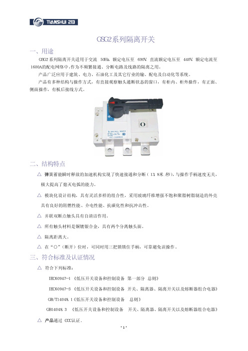
GSH2系列转换开关
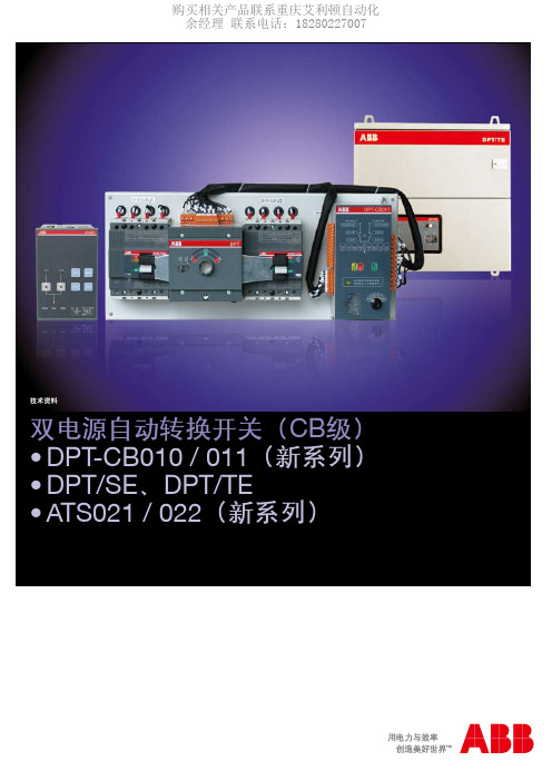
ABB DPT ATS电源自动转换开关
次/min
10
机械寿命
操作次数
次
10000
工作环境温度
℃
- 5 ~ +40
储存温度
℃
- 40 ~ +70
接线端子螺栓拧紧力矩
Nm 2.8
7
8
转换断路器操作力矩
Nm 2
4
重量(不带附件)
2极断路器
kg 7.6
-
-
3极断路器
kg 7.9
10.3
11.5
4极断路器 1)为断路器参数(不包括电动操作机构)。
√
√
-
√
√
√
√
√
√
√
手动 / 自动 / 合Ⅰ/ 双分 / 合Ⅱ
自投自复 / 互为备用
3A / 250Va.c.(28Vd.c.)
≤ 2000
-25 ~ +55
-40 ~ +70
DPT-CB的转换时间
型号
转换动作时间 1)
总动作时间 2)
DPT63 - CB010_C_ _
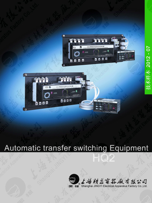
HQ2系列自动转换开关
型号
最小总转换 动作时间 (Tmin)
分闸延时 t1
合闸延时 t2
HQ2 R(S、F)-63~250 HQ2 R(S、F)-400
HQ2 R(S、F)-630、800
2.0s
0.5s~60s (连续可调)
0.5s~60s (连续可调)
技术说明: 1)总转换动作时间T=t1+t2+tg(tg为固有动作时间)。 2)ATSE 出 厂 时 , 其 总 转 换 动 作 时 间 调 整 在 Tmin=2.0s 。 最 小 总 转 换 动 作 时 间 Tmin 是 在 t1=0.5s,t2=0.5s条件下测得的。
控制器的工作原理简述如下: 控制器对常用电源和备用电源的三相电压同时进行检测,当电源出现偏差(欠电压、过电压、缺相)时,内部电 路对六个电压幅值及相位的检测结果进行判断,处理结果通过延时后,驱动相应的指令继电器向电动操作机构发 出分闸、合闸指令。上述处理结果用 12 个发光二极管在面板上显示。通过面板上的四个按钮开关可以设定四种 工作模式(“自动控制”、“常用电源”、“备用电源”、“断电(再扣)”)、分闸延时时间 t1、合闸延时 时间 t2 及欠电压动作值可以通过面板上相应的调节电位器进行调节。HQ2 自动转换开关的电气原理图见二次回 路接线图。
使用寿命表 型号
HQ2-63~250 HQ2-400
HQ2-630、800
机械寿命 5000 3000 2500
电寿命 1000 1000 500
使用寿命总次数 6000 4000 3000
主要技术数据及性能表
型号
配用的 断路器型号
额定电流 Ie(A)
额定绝缘 电压 Ui (V)
额定工作 电压 Ue (V)
施耐德万高双电源自动转换开关
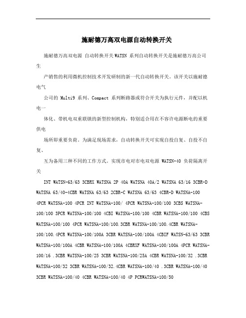
施耐德万高双电源自动转换开关施耐德万高双电源自动转换开关WATSN 系列自动转换开关是施耐德万高公司生产销售的利用微机控制技术开发研制的新一代自动转换开关。
该开关以施耐德电气公司的 Multi9 系列、Compact 系列断路器或符合开关为执行元件,并配以机电一体化、带机电双重联锁的新型控制机构,特别适合用在不容许电源断电的重要供电场所即重要负荷。
为满足现场需求,自动转换开关可实现自投自复、自投不自复、互为备用三种不同的工作方式。
实现市电对市电双电源 WATSN-40 负荷隔离开关INT WATSN-63/63 3CBRX WATSNA 2P 40A WATSNA 40A/2 WATSNA 63/16 3CBR-D WATSNA 63/40-4CBR WATSNA 63/63 2CBR-C WATSNA 63/63 4CBR-D WATSNA-1004PCR WATSNA-100 4PCR INT WATSNA-100/ 4PCR WATSNA-100/100 3CBS WATSNA-100/100 3PCR WATSNA-100/100 4CBI WATSNA-100/100 4CBR WATSNA-100/100 4CBS WATSNA-100/100 4PCR WATSNA-100/100.3CBR WATSNA-100/100.4CBR WATSNA-100/100.4PCR WATSNA-100/100A 3CBR WATSNA-100/100A 4CBIF WATSN-63/63 3CBR WATSNA-100/100A 4CBR WATSNA-100/100A 4CBRXF WATSNA-100/100A 4PCR WATSNA-100/16 .3CBR WATSNA-100/25 3CBR WATSNA-100/25A 4CBR WATSNA-100/32 .3CBR WATSNA-100/32 3CBR WATSNA-100/32.4CBR WATSNA-100/40 .3CBR WATSNA-100/40 3CBR WATSNA-100/40 4CBR WATSNA-100/40 4P PCRWATSNA-100/503CBRWATSNA-100/50.4CBRWATSNA-100/50A 4CBRWATSNA-100/63 3CBRWATSNA-100/63 4CBRWATSNA-100/63 4PPCRWATSNA-100/63.3CBRWATSNA-100/63A 4CBRWATSNA-100/63A 4CBTRWATSNA-100/63A 4PCRWATSNA-100/80 4CBRWATSNA-100/80 4CBR XFWATSNA-100/80 4PCRWATSNA-100/80.3CBRWATSNA-100/80.3CBSWATSNA-100/80.4CBRWATSNA-100/80A 3CBRWATSNA-100/80A4CBRWATSNA-100/80A.3CBR-XWATSNA-100-100-3CBIWATSNA-100-100-4PCRWATSNA-100-40-3CBRSTR22SEWATSNA-100A4PCRWATSNA-125/3RWATSNA-125A/4PCRWATSNA-16/162CBRWATSNA-160.4CBRWATSNA-160/1004PCRWATSNA-160/100.4CBRWATSNA-160/100A 4CBRWATSNA-160/100A4PCRWATSNA-160/125 4CBRWATSNA-160/125.3CBRWATSNA-160/125A 4CBRWATSNA-160/125A 4PCRWATSNA-160/160 3CBIWATSNA-160/160 3CBRWATSNA-160/160 4CBRWATSNA-160/160.3CBRWATSNA-160/160.3CBSWATSNA-160/160.3CBS手柄WATSNA-160/160.3PCIF WATSNA-160/160.4CBR WATSNA-160/160.4PCR WATSNA-160/160-4CBR WATSNA-160/160A 3PCR WATSNA-160/160A 4CBR WATSNA-160/160A 4CBRXF WATSNA-160/160A 4PCR WATSNA-160-125-3CBI WATSNA-160-40-3CBI WATSNA-160A/120A 3CBR WATSNA-160N/125-3CBR WATSNA-200A/4PCR WATSNA-250/125 4CBR WATSNA-250/160 4PCR WATSNA-250/200 4PCR WATSNA-250/200.3CBR WATSNA-250/200.4CBR WATSNA-250/200.4CBS WATSNA-250/200A 4CBR WATSNA-250/250 3CBS WATSNA-250/250 4BCR WATSNA-250/250 4PCR WATSNA-250/250.4CBR WATSNA-250/250A 4CBR WATSNA-250/250A.3CBR WATSNA-250/H200A 3CBR WATSNA-250/H250A 3CBR双电源是指:一种由微处理器控制,用于电网系统中网电与网电或网电与发电机电源启动切换的装置,可使电源连续源供电。
欣灵 ( CB级)双电源自动切换开关系列 说明书
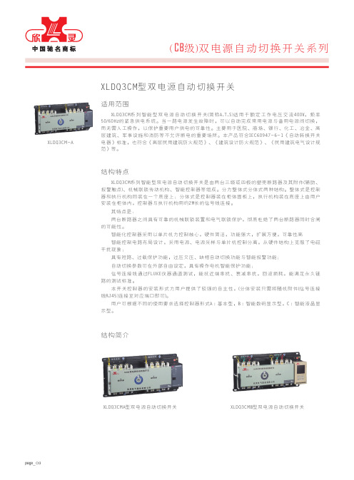
适用范围XLDQ3CM型双电源自动切换开关XLDQ3CM系列智能型双电源自动切换开关(简称A.T.S)适用于额定工作电压交流400V,频率50/60Hz的紧急供电系统。
当一路电源发生故障时,可以自动完成常用电源与备用电源间切换,而无需人工操作,以保护重要用户供电的可靠性。
主要用于医院、商场、银行、化工、冶金、高层建筑、军事设施和消防等不允许断电的重要场所。
本产品符合IEC60947-6-1《自动转换开关电器》标准,也符合《高层民用建筑防火规范》、《建筑设计防火规范》、《民用建筑电气设计规范》等。
结构特点XLDQ3CM系列智能型双电源自动切换开关是由两台三级或四极的塑壳断路器及其附件(辅助、报警触点)、机械联锁传动机构、智能控制器等组成。
分为整体式分体式两种结构。
整体式是控制器和执行机构同装在一个底座上;分体式是控制器装在柜体面板上,执行机构装在底座上由用户安装在柜体内,控制器与执行机构用约2M长的信号线连接。
其特点是:两台断路器之间具有可靠的机械联锁装置和电气联锁保护,彻底杜绝了两台断路器同时合闸的可能性。
智能化控制器采用以单片机为控制核心,硬件简洁,功能强大,扩展方便,可靠性高 智能控制电路布局设计,采用电源、电源采样与单片机控制分离,从硬件结构上克服了电磁干扰现象;具有短路、过载保护功能,过压欠压、缺相自动切换功能与智能报警功能;自动切换参数可在外部自由设定,具有操作电机智能保护功能;信号连接线通过FLUKE仪器通道测试,能抗近端串扰、衰减串扰,回波损耗,能满足永久链路的测试标准。
本开关控制器的安装形式为用户提供了较强的自主性,(分体安装只需将随机附件(信号连接线RJ45)连接至对应端口即可)。
用户可根据不同的使用要求选择控制器形式A :基本型,B :智能数码显示型,C :智能液晶显示型。
结构简介XLDQ3CMA型双电源自动切换开关XLDQ3CMB型双电源自动切换开关page _09XLDQ3CM-A(CB 级)双电源自动切换开关系列低压配电产品选型LOW-VOLTAGE POWER-DISTRIBUTION PRODUCTS CATALOGUE 周围空气温度:a. 上限值不超过+40℃;b. 下限值不超过-10℃;c. 24h平均值不超过+35℃;海拔:安装地点的海拔不超过2000m;大气条件:大气的相对湿度在周围最高温度+40℃ 时不超过50%,在较低的温度下可以有较高的湿度,在最湿月的月平均最低温度+25℃时,该月的平均最大相对湿度为90%,并考虑到因温度变化在表面上的凝露。
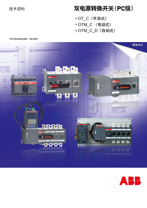
双电源转换开关-PC级
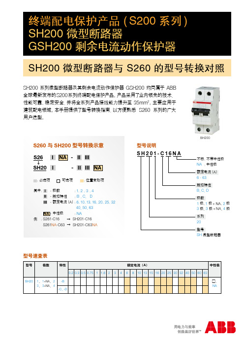
SH200-GSH200
ዐࡔఢഋ 830002
ዐࡔဇูᇱ 030002
ႎࣀٷন 66 ࡽ
ߛႎਸ݀൶ߛႎୟ
ዐୟ 86 ࡽ
ުဇন 69 ࡽ
ాࠟࡔाٷ৶ ی23 ֫
ߛႎࡔाฆခዐ႐ຕஓٷေ 16 ֫ ዐආ࠽ ׇ6 ୍ Bፗ
ဇࡔाஹᅟዐ႐ဇ୍ 10 ֫ 1009Aࡽ
ࣆۉ: (0471) 6916 330
ዐᇱဇୟ 220 ࡽ ᇧࡔٳाஹᅟዐ႐ A ፗ 1006
ࣆۉ: (0531) 8609 2726 دኈ : (0531) 8609 2724
70 ࣆۉ70 : (0731) 8268 308582 52 دኈ : (0731) 847404 575019 70
ࣆۉ: دኈ52:
型号说明
GSH201□AC□-C63/0.03□
特殊应用 不标 :无
GSH200
AP-R:抑制瞬态干扰型
(动作时间:10 - 200ms)
额定剩余电流(A)
0.01、0.03、0.1、0.3
额定电流(A)
6 - 63
脱扣特性
B、C、D
动作特性及时间
不标 :瞬动型(<100ms)
S :选择型(130 - 500ms)
防护等级 隔离指示 认证信息
上下端子可连接汇流排 U 形接线端子 IP20 手柄 CCC、RoHS、CE、CB
外形尺寸图(mm)
S260 S260-B、C、D S260NA - C、D
1、1+NA、2、3、4 B、C、D、K 0.5 - 63 A 6 kA (B、C、D) 6 kA (K) 0.75 - 25 ( ≤ 40 A) 0.75 - 35 ( 50、63 A) 上下端子可同时接导线及汇流排 U 形接线端子
甘肃省工业和信息化委员会关于公布2011年度甘肃省优秀新产品新技术名单的通知
甘肃省工业和信息化委员会关于公布2011年度甘肃省优秀新产品新技术名单的通知文章属性•【制定机关】甘肃省工业和信息化委员会•【公布日期】2012.11.23•【字号】甘工信发[2012]947号•【施行日期】2012.11.23•【效力等级】地方规范性文件•【时效性】现行有效•【主题分类】企业正文甘肃省工业和信息化委员会关于公布2011年度甘肃省优秀新产品新技术名单的通知(甘工信发〔2012〕947号)各市、州工信委,有关单位:为加大技术创新成果宣传力度,促进新产品新技术的研发和推广应用,进一步调动广大企事业单位研发新产品新技术的积极性,充分发挥技术创新对工业经济发展的支撑作用,在各市州、有关行业协会及部分中央和省属企业申报的基础上,经审查筛选并组织专家评审,认定“GSC3-09~95Z系列直流操作交流接触器”等69项新产品新技术为2011年度甘肃省优秀新产品新技术。
现将名单予以公布(见附件),并对研发生产单位及主要研发人员颁发荣誉证书。
甘肃省优秀新产品新技术为省部级奖励,获奖证书可作为研发人员评定职称、晋升职务的依据。
研发单位可根据本单位实际,对研发人员予以适当奖励,奖励资金可纳入生产成本。
希望各获奖单位发扬成绩,继续努力,进一步加大创新工作力度,争取更大成效。
全省广大企业和科技工作者要学习先进单位的典型做法和成功经验,建立健全创新体系,完善创新机制,加大创新投入,切实加强新产品新技术的研发与推广应用,提高生产技术水平,增强企业核心竞争力,为全省工业经济又好又快发展做出应有贡献。
附件:2011年度甘肃省优秀新产品新技术名单甘肃省工业和信息化委员会2012年11月23日。
3 ABB选型价格查询手册 转换开关 低压产品
1 断路器类产品 空气断路器 - Emax...................................................................................................1/1 塑壳断路器 - Tmax XT、Tmax................................................................................1/14
连接装置 - 接线端子 - 螺钉卡箍连接、弹簧连接、ADO绝缘移位连接...............................2/60 - 工业连接器........................................................................................................2/69
双电源转换开关(PC级) - OT_C(手动式)................................................................................................3/3 - OTM_C(电动式).............................................................................................3/6 - OTM_C_D(自动式).........................................................................................3/6
GS-Hydro

GS-Hydro 中国预制
• • • 31名拥有丰富船厂工作经验的管道工 5名能说英语的现场安装主管 预制机(1台),弯管机(12台),扩口 机(12台),Walform机(8台),沟槽 机(1台),冲洗机(5台),耐压测试 机(1台) 在中国数以千记的成功项目经验
•
服务
为新建项目提供的服务
GS-Hydro 为新建项目提供广泛的服务: • • • • • • 现场测量 设计 预制 项目管理 安装与监督 冲洗和压力测试
•
•
•
GS-Hydro 无焊接技术
Walform接头连接42毫米以下
• • • • DIN 2353 本体和螺母 WF-WD 24° 密封面 公制管
•
管径在42mm以下
GS-Hydro 全方案提供
设计
工程
GS-Hydro 可以提供所有的工程服务 • • • • • • • 布置图 安装图纸 车间预制图纸 管道选择方案 管道支架图纸 管道压力分析计算(FEM-分析) 法兰压力分析计算
服务的好处包括,项目交付及时,良好的 质量和有效的成本控制。
海洋工程的售后服务
GS-Hydro正在建立其优质的售后市场服务, 包括以下内容的全面产品: • • • 现场调研 液压系统可靠性评估 软管管理 – 软管管理设定 – 预防性的更换 – 紧急更换 修改 – 少量的修改,如停机维修 – 主要的修改,如重新升级
•
• •
无焊接管道解决方案的优势
节省整个系统全生命周期的成本 1. 降低总安装系统成本,缩短的安装时间 2. 降低冲洗时间和成本 3. 减少维修和保养的需求 4. 缩短在生产过程中的维修与保养时间 5. 更少的影响生产 卓越的技术 - 公认的质量,无泄漏 1. 多个船级社批准 2. 连贯的品质源于机器加工和组件预制 3. 简便,可靠和安全 4. 快速,灵活的安装 5. 适用于不同的材料 6. 环保
直流接触器GSZ2
400
24
48
0.3 0Leabharlann 25 0.1 0.3
0.1
0.3
0.1
±20%US
20 ± 5OO C 冷态 动作 电压
吸合 Vmax 释放 V
18
28
18
28
18
28
18
28
6.5 ~ 2.4
12 ~4.8
6.5 ~ 2.4
12 ~4.8 6.5 ~ 2.4
-1-
参 数 规 格
绝缘电压 (Ui )V
约定发热电流 lth (A)
主电 路 DC
额定工作电压 Ue (V)
额定工作电流 le (A)
触 点 接 触 压 降
线圈额定电压 (VDC )
控制 电路 DC
20 OC 额定电压下 线圈电流 (A DC )
电源电压波动范围 (最高环境温度
40O C )
GSZ2- 5 0D/24V
GSZ2
GSZ2- 50S/2
4V
GSZ2- 5 0S/48V
50
50
不大于 80mV (额定负载下 )
24
48
0.3
0.25 0.1
GSZ2- 1 00D/24
V
GSZ2- 100
GSZ2- 1 00S/24
V
GSZ2- 1 00S/48
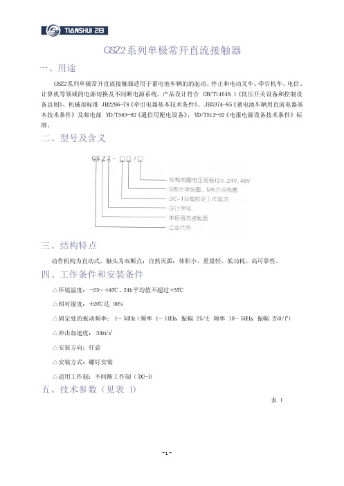
二、型号及含义
三、结构特点
动作机构为直动式,触头为双断点;自然灭弧;体积小、重量轻、低功耗、高可靠性。
四、工作条件和安装条件
△环境温度:-25~+40℃,24h 平均值不超过+35℃ △相对湿度:+20℃达 90% △固定处的振动频率:1~50Hz(频率 1~10Hz,振幅 25/f;频率 10~50Hz,振幅 250/f2) △冲击加速度:30m/s2 △安装方向:任意 △安装方式:螺钉安装 △适用工作制:不间断工作制(DC-1)
ATS系列自动转换开关

MX250控制器
N
E
1 P2
L 瞬间并联转换型
ZTS系列双旁路型ATS
应用
旁路隔离型ATS设计用于关键电力场合,如数据中心、机场、金融、通信、半导体工厂等, 其最大的优点在于提前或现场规避ATS机械故障导致的断电风险:当ATS发生机械故障 并需要停电维护时,越来越多的重要电力场合如数据中心并不支持长时间断电,同时 受限于UPS的后备时间(一般不大于30分钟),GE Zenith为客户提供了旁路隔离型ATS 产品,当ATS发生故障需要现场维护时,可提前将负载手动转换至旁路开关,故障的 ATS可通过导轨或ATS自带滑轮轻松移出进行维护,完成维护后,转换开关可重新移 入测试位置进行功能测试、并恢复正常供电,整个维护过程从旁路负载、转换开关 维护、转换开关功能测试与恢复正常运行,负载均能保持正常供电。
MX60微处理器控制面板 MX90微处理器控制面板
1
ZTG系列自动转换开关
应用
ZTG系列致力于满足更高要求的关键电力场合,广泛应用于机场、酒店、通信、电厂 等低压柜双电源切换,设计上具有以下特点: • 额定电流可达3200安培,满足常规容量需求 • 采用MX150控制,配备大屏幕液晶面板,所有参数现场可调 • 引入GE独特可控硅整流方式,使线圈的激磁控制更加精准、可靠 • ZTG系列提供两种转换方式开关:标准转换ZGS型与中间位延时转换ZGD型
开启此功能可实现同步转换可选rs485通讯卡方便后台监控系统集成技术规范额定电流a短路电流耐受值配合断路器406310035ka16020050ka26032040065ka现场参数设定常用备用电源欠压检测7595失效可调75100恢复可调常用备用电源过压检测7595失效可调75100恢复可调发电机启动延时p0999秒可调转换至备用侧延时w0999秒可调回切至常用侧延时t0999秒可调发电机冷却时间u0999秒可调额定电流a极数尺寸高h宽w深d开关本体40634p3p2302161941151004p3p2302822521151602004p3p2303182781152603204004p3p287423363152mx60微处理器控制面板mx90微处理器控制面板ztg系列自动转换开关应用ztg系列致力于满足更高要求的关键电力场合广泛应用于机场酒店通信电厂等低压柜双电源切换设计上具有以下特点
货物组件材料配置表
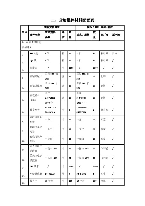
二、货物组件材料配置表项目货物需求投标人(唯一确定)响应序号元件名称型式规格,参数单位数量型式、规格数量原厂商原产地1、本体(写明物资描述)1.HDMI线3米根303米30秋叶原日本2.vga线3米根303米30秋叶原/ 3.窗帘钩 / 个1000 / 1000 / /4. 自钻钻尾丝直径5MM 长2CM盒10直径5MM 长2CM10北塔/5. 自钻钻尾丝直径5MM 长3CM盒10直径5MM 长3CM10北塔/6. 自攻螺丝(黑)直径3.5*25MM1000个盒10直径3.5*25MM1000个10北塔/7. 转换开关LAY3-11X2660V/10A个2LAY3-11X2660V/10A2德力西/8. 有线电视分配器一分二个10一分二10西蒙/9. 有线电视分配器一分三个10一分三10西蒙/10. 有线电视分配器一分四个10一分四10西蒙/11. 荧光灯电子镇流器一拖一 40W个20一拖一 40W20飞利浦/12. 荧光灯电子镇流器一拖二 40W个20一拖二 40W20飞利浦/13.LED线卡 / 个2000 / 2000 / / 14.小便感应器FU-613AC套5FU-613AC5九牧/ 15.线鼻子16平方个10016平方100凤凰/序号元件名称型式规格,参数单位数量型式、规格数量原厂商原产地16.线鼻子25平方个10025平方100凤凰/ 17.线鼻子35平方个10035平方100凤凰/ 18.五孔面板10A个17010A170罗格朗/ 19.投光灯50W LED个550W LED5佛山/ 20.头灯1566个515665公狼/ 21.铜球阀DN15个20DN1520巨泉/ 22.铜球阀DN20个20DN2020巨泉/ 23.塑铜线4MM 100米盘24MM 100米2昆仑/24. 塑铜线 2.5MM 100米盘22.5MM 100米2昆仑/25.塑铜线6MM 100米盘26MM 100米2昆仑/ 26.塑铜线10MM 100米盘210MM 100米2昆仑/ 27.塑铜线16MM 100米盘216MM 100米2昆仑/28. 塑壳断路器3P 200A250F个13P 200A250F1施耐德/29.四联开关 / 个10 / 10飞利浦/ 30.四极插头16A个216A2公牛/ 31.水龙头7116-183个107116-18310九牧/32. 双联双控开关Q8个40Q840飞利浦/33.双联开关Q8个20Q820飞利浦/ 34.双联开关Q8 212-2个20Q8 212-220飞利浦/ 35.声控开关继电器型个20继电器型20松本/序号元件名称型式规格,参数单位数量型式、规格数量原厂商原产地36.生料带 / 卷50 / 50潜水艇/ 37.射灯杯12V35W个3012V35W30雷士/ 38.空白面板 / 个50/ 50 / / 39.三联开关Q8个10Q810飞利浦/ 40.三孔面板16A个1016A10罗格朗/ 41.三极插头10A个4010A40公牛/ 42.三极插头16A个4016A40公牛/ 43.日光灯管36W根15036W150飞利浦/ 44.日光灯管30W根15030W150飞利浦/ 45.启辉器C1O 220v个50C1O 220v50飞利浦/ 46.启辉器C1O 110V个50C1O 110V50飞利浦/ 47.灭蝇灯30W套3030W30佛山/48. 面盆高管冷热水龙头32189-205个332189-2053朝阳/49. 面盆单冷水龙头7613-080套37613-0803九牧/50.门插不锈钢材质个25不锈钢材质25巨泉/ 51.螺旋节能灯8W个3008W300欧司朗/ 52.螺旋节能灯15W个30015W300欧司朗/ 53.螺旋节能灯23W个30023W300欧司朗/ 54.铝塑管DN25米20DN2520日丰/ 55.漏电开关3P 32A个103P 32A10ABB/序号元件名称型式规格,参数单位数量型式、规格数量原厂商原产地56.漏电断路器1P+N 16A个201P+N 16A20ABB/ 57.漏电断路器1P+N 25A个201P+N 25A20ABB/58. 漏电断路器GSH202-C2020A 2P个20GSH202-C2020A 2P20ABB/59. 漏电断路器GSH202-C1010A 2P个20GSH202-C1010A 2P20ABB/60.漏电断路器4P 100A个204P 100A20ABB/ 61.漏电断路器4P 60A个204P 60A20ABB/ 62.漏电断路器16A 220V 3P个2016A 220V 3P20ABB/ 63.漏电断路器25A 220V 3P个2025A 220V 3P20ABB/ 64.漏电断路器32A 220V 3P个2032A 220V 3P20ABB/ 65.淋浴软管H2101 200CM根50H2101 200CM50九牧/66. 淋浴器组件CF-9071.100.50套3CF-9071.100.503美标/67.淋浴器组件H200AR套3H200AR3科勒/68. 淋浴喷头(含管)DM707CFR套30DM707CFR30TOTO/69.冷热水龙头801-1套15801-115樱花/ 70.冷热水龙头L169套15L16915朝阳/71. 宽胶带5.3cm 大卷透明米黄色卷505.3cm 大卷透明米黄色50天泰/72.空气断路器1P/16A个201P/16A20ABB/ 73.空气断路器1P/10A个201P/10A20ABB/ 74.空气断路器1P/25A个201P/25A20ABB/序号元件名称型式规格,参数单位数量型式、规格数量原厂商原产地75.空气断路器3P/16A个203P/16A20ABB/ 76.空气断路器3P/25A个203P/25A20ABB/77. 空调液晶温控器HL108DB2个20HL108DB220海林/78.空调电机25W台3025W30伟华/ 79.进水阀B3800E个5B3800E5威迪亚/ 2、必备的备品备件1.节能灯8W只3008W300飞利浦/ 2.节能灯3U 8W个3003U 8W300飞利浦/ 3.节能灯3U 14W个3003U 14W300飞利浦/ 4.节能灯3U 18W个3003U 18W300飞利浦/ 5.节能灯6U 105W套206U 105W20飞利浦/ 6.节能灯65W 白光只5065W 白光50飞利浦/ 7.节能灯3U 23W个1503U 23W150飞利浦/ 8.交流接触器220V 25A个10220V 25A10施耐德/ 9.交流接触器220V 20A个10220V 20A10施耐德/ 10.换气扇BPT12-13C台30BPT12-13C30正野/ 11.环形镇流器32W个2032W20飞利浦/12. 环形灯管镇流器22W22W个2022W22W20佛山/13.环形灯管32W只2032W20飞利浦/ 14.环形灯管22W根2022W20飞利浦/序号元件名称型式规格,参数单位数量型式、规格数量原厂商原产地15. 护套线3芯*2.5MM100米盘53芯*2.5MM100米5昆仑/16. 护套线3芯*6MM100米盘53芯*6MM100米5昆仑/17.滚刷 / 把50 / 50多乐士/18. 方形灯镇流器21W个2021W20佛山/19.方形灯管21W根2021W20佛山/ 20.电子镇流器40W个1540W15四通/ 21.电子镇流器一拖二 20W个20一拖二 20W20飞利浦/ 22.电子变压器60W个560W5飞利浦/ 23.电视面板 / 个10/ 10罗格朗/ 24.电视AV线1分三根101分三10叶秋源/25. 电缆10平方 100米盘210平方 100米2小猫/26.电话线4芯盘24芯2安普/ 27.地漏T202个20T20220坦克/ 28.灯珠12V 35W个2012V 35W20飞利浦/ 29.灯泡40W个5040W50飞利浦/ 30.灯管T8 18W根30T8 18W30佛山/ 31.灯管T8 36W根30T8 36W30佛山/32. 灯管T5 24W根30T5 24W30三雄极光/33.单联开关Q8个20Q820飞利浦/序号元件名称型式规格,参数单位数量型式、规格数量原厂商原产地34. 不锈钢丝进水管30CM根530CM5恒一/35. 百叶排气风扇FA-B-350台10FA-B-35010百丽/36.八字阀A123个40A12340朝阳/37. T5节能灯管T5 28W 支100 T5 28W 100三雄极光/38. T5灯架(含灯管)T5 24W套50T5 24W50欧司朗/39. T5灯架(含灯管)T5 28W套50T5 28W50欧司朗/40. T5灯架(含灯管)T5 21W套100T5 21W100 /41. T4灯架(含灯管)14W套5014W50三雄极光/42. T4灯架(含灯管)12W套5012W50三雄极光/43. T4灯架(含灯管)11W套5011W50三雄极光/44.PVC弯头DN110个30DN11030联塑/ 45.pvc管DN50米20DN5020联塑/ 46.pvc管DN200米20DN20020联塑/ 47.pvc管DN110米20DN11020联塑/48. PVC变径直接160变110个10160变11010联塑/49.PPR水管直径15MM米20直径15MM20联塑/50. LED一体灯(灯管+支架)T5 16W套40T5 16W40三雄极光/序号元件名称型式规格,参数单位数量型式、规格数量原厂商原产地51. LED一体灯(灯管+支架)T8 16W套40T8 16W40三雄极光/52. led吸顶灯(声光控)16W套516W5飞利浦/53. LED灯带插头(防水)220V个45220V45ABB/54.LED灯12V12W个2012V12W20飞利浦/ 55.LED灯12V30W个2012V30W20飞利浦/ 56.LED灯12V16W个2012V16W20飞利浦/ 57.LED灯带(高亮)8W米800(高亮)8W800飞利浦/ 58.LED草坪灯 个20 20 /59. LED平板吸顶灯 套20 20 /60. 自喷漆400ML 12瓶/箱瓶20400ML 12瓶/箱20三合/61.云石胶4L桶54L5大力士/ 62.云石胶1L桶51L5大力士/ 63.万能胶 1.8L桶6 1.8L6哥俩好/ 64.脱漆剂 3.5KG桶5 3.5KG5三合/ 65.涂料17L桶1017L10立邦/ 66.塑钢土500G袋2500G2嘉诚信/ 67.木蜡油 2.5L桶10 2.5L10简诺/ 68.光油自喷漆400ML瓶10400ML10三合/ 69.防锈漆(铁16KG桶216KG2京狮/序号元件名称型式规格,参数单位数量型式、规格数量原厂商原产地红)70. 防锈漆(灰色)16KG桶216KG2泰利/71.防锈漆15KG桶215KG2泰利/ 72.防锈剂500ML瓶5500ML5三合/ 73.堵漏灵5KG袋205KG20三棵树/ 74.堵漏灵2KG袋202KG20雨虹/ 75.电镀喷漆350ML瓶2350ML2三合/76. 玻璃胶24桶/箱白色桶7024桶/箱白色70三棵树/77. 玻璃胶24桶/箱透明桶7024桶/箱透明70三棵树/78.玻璃胶180ML 737支50180ML 73750道康宁/ 79.玻璃胶黑色支50黑色50恒硅/ 80.pvc胶1KG桶301KG30联塑/ 81.ab胶40G支1040G10哥俩好/ 82.502胶40g个5040g50502/ 83.铁丝8#斤2008#200 / 84.铁丝16#斤20016#200 / 85.腻子粉25KG袋525KG5美巢/ 86.腻子粉18KG袋518KG5美巢/87. 镀锌管DN15 国标6米根20DN15 国标6米20利达/88. 镀锌管DN20 国标6米根20DN20 国标6米20利达/序号元件名称型式规格,参数单位数量型式、规格数量原厂商原产地89. sbs防水卷材4MM卷24MM2雨虹/3、专用工具和仪器仪表1.相序表UT-262套5UT-2625优利德/ 2.水压力表 1.6MPA块5 1.6MPA5京水/3. 数字钳形万用表UT204A个10UT204A10优利德/4.麻花钻头19只装盒8019只装80博士/ 5.冲击钻头直径6MM根10直径6MM10博士/ 6.冲击钻头直径8MM根10直径8MM10博士/ 7.冲击钻头直径10MM根10直径10MM10博士/ 8.冲击钻头直径12MM根10直径12MM10博士/ 9.冲击钻头直径14MM根10直径14MM10博士/ 10.冲击钻头直径16MM根10直径16MM10博士/ 11.羊角锤92331把109233110世达/ 12.压线钳91119把5911195世达/ 13.外卡弹簧钳72001把5720015世达/ 14.三角锉3994把539945世达/15. 全抛光两用扳手套装9026套590265世达/16.偏口钳70615A把1070615A10世达/17. 内六角扳手套装(球头)09106 12件套套309106 12件套3世达/序号元件名称型式规格,参数单位数量型式、规格数量原厂商原产地18. 内六角扳手套装(球头)09124 9件套套309124 9件套3世达/19.内六角扳手84318把5843185世达/ 20.内六角扳手9107套391073世达/ 21.内卡弹簧钳72005把5720055世达/ 22.抹泥刀95201把5952015世达/23. 螺丝刀(一字)62213把206221320世达/24. 螺丝刀(一字)61314把206131420世达/25. 螺丝刀(十字)62313把206231320世达/26. 螺丝刀(十字)61213把206121320世达/27.螺丝刀66206把206620620世达/ 28.螺丝刀62308把206230820世达/29. 六角风动套筒(16件)34605-34620套234605-346202世达/30.两用扳手9027套290272世达/ 31.拉铆枪90502把2905022世达/ 32.克丝钳72203/8寸把1072203/8寸10世达/ 33.卡簧钳9251套10925110世达/ 34.绝缘偏口钳72615把207261520世达/ 35.绝缘尖嘴钳72610把207261020世达/序号元件名称型式规格,参数单位数量型式、规格数量原厂商原产地36.绝缘钢丝钳72626把207262620世达/ 37.锯弓93414把109341410世达/ 38.锯弓93405把109340510世达/39. 金刚石锉刀套装165405套21654052老A/40.角磨机GWS8-100C台2GWS8-100C2博士/ 41.尖嘴钳72402/8寸把2072402/8寸20世达/42. 活动扳手47203200MM把1047203200MM10世达/43.活动扳手47252把104725210世达/ 44.活动扳手34605-34620套234605-346202世达/ 45.活动扳手47253把104725310世达/ 46.黄油枪97204把2972042世达/47. 花形内六角扳手09715 9件套套509715 9件套5得力/48.盒尺3米把103米10世达/ 49.管钳70824 300MM把870824 300MM8世达/ 50.管钳70825 350MM把870825 350MM8世达/ 51.管钳70827把8708278世达/52. 工具套装(56件)9536套295362世达/53. 工具套装(27件)6005套260052优利德/54. 非接触性电笔UT-12C支3UT-12C3世达/序号元件名称型式规格,参数单位数量型式、规格数量原厂商原产地55. 多功能螺丝刀9346套10934610老A/56. 多功能测电笔剥线钳二合一LA515001套10LA51500110世达/57.断线钳93507把109350710老A/ 58.电烙铁SI-131G把5SI-131G5世达/ 59.电缆切割钳72502把107250210世达/ 60.锉刀9910套10991010世达/ 61.锉刀3803套10380310世达/ 62.锉刀3830套10383010世达/ 63.锉刀3802套10380210博士/64. 充电电钻TSR1080-2-1i个5TSR1080-2-1i5博士/65.充电电钻TSR1440-LI个2TSR1440-LI2博士/ 66.充电电钻GSR12-2-1I把2GSR12-2-1I2世达/ 67.测电笔62602支206260220老A/68. 不锈钢防磁镊子81350套158135015世达/69.剥线钳91108把5911085世达/ 70.玻璃胶枪90510/9寸把1090510/9寸10世达/ 71.玻璃胶枪90511/15寸把1090511/15寸10得力/ 72.壁纸刀架DL004把10DL00410世达/ 73.壁纸刀93430把209343020世达/序号元件名称型式规格,参数单位数量型式、规格数量原厂商原产地74.半圆锉刀121001把1012100110世达/ 75.扳手套筒9510套195101得力/ 76.扳手300MM/12寸个10300MM/12寸10世达/ 77.扳手47251把104725110世达/78. vde绝缘螺丝批(可换头)09301A 7件套套1009301A 7件套10世达/编制说明:1、请抄录已发送邮件的招标文件技术规范书《货物组件材料配置表》或《供货范围一览表》的数据、信息或表述,填写本表对应条目“项目货物需求”栏,并在规定位置逐条逐项对应作出应答。
FAS系统的组网方式
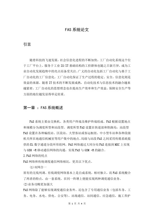
FAS系统论文引言随着科技的飞速发展,社会信息化进程的不断加快,工厂自动化系统这个位于工厂平台上,服务于工业IS/IT基础结构的工控群体也随之日新月异,成为工业自动化发展趋势中的亮点而备受关注。
广义的自动化包括工厂自动化与基于工厂自动化的工厂信息化,工厂自动化保证了生产过程的稳定、安全,信息化则是效益的来源。
随着IT技术的不断发展成熟,自动化技术与信息技术的融合越来越紧密,工厂自动化的思想理念也在提高生产效率和生产效益,保障安全生产等方面的地位越发显得举足轻重。
第一章:FAS系统概述FAS系统主要由交换机、各类用户终端及维护终端组成。
FAS根据设置地点和规模分为调度所型和站段型。
调度所型FAS设置在快道部和铁路局;站段型FAS设置在各种编组站、区段站、大型客站或客运枢纽、中小型车站和各种段级机关所在地通信机械室等用户集中的地点。
局级与站段FAS之间采用传箱系統提供的E1数字通道分段环形组网,PAS网络通过大同分局FAS连接到MSC上实现与GSH -R移动通信网络的沟通,实现FAS与GSM -R的融合。
2.FAS网络的忧点FAS网络和传统调度通信网络相比,更具以下优点。
(1)双网合一原有的无线列调、有线调度网络基本上是自成系统,相对独立,而FAS系统酸合了两者的特点,由一套系统。
在同一终增上便能实现两种调度通信业务。
(2)业务功鲍更加强大FAS网络除了能够实现调度通信业务外。
还包含了专用通信业务(包括车务、工务、电务、水电、供电。
公安等),站场通信。
站间通信、应急通信,施工养护通信和道口通信等。
(3)链路时隙利用率更高数字调度通信系统中路局与站段设备之间的通道资源采用固定时隙的分配方式给用户终端。
而FAS网络的终墙用户则采用拔号方式抢占链路时隙。
并且根据通信的优先级别拌队等候来保证如紧急呼叫、列车调度通信等饭别较高的业务。
实现了通道资源共享,有效的提高了链路的利用率[1]。
(4)呼叫方式多样化GSM -R调度通信中可以采用多种呼叫方式,如ISDN呼叫、SISDN呼叫、功能号呼叫、短号码呼叫等等。
ASCO 230系列自动转换开关

Emission, Class A • EN61000-3-2: Harmonic Current Emission,
Class A • EN61000-3-3: Limits of Voltage fluctuation
I
图例 1 132A-132C 示意图
II 0
I
图例 2 132D-132F 示意图
5
保障您的重要数据不因停电而丢失
230 系列 ATS 外形尺寸及重量 *
32A、40A⋯⋯160A
78 104 117 184 126 221
181.6 100 116 126 130 150.5
A
200A、225A、250A
100A
125A
160A
200A
225A
250A
315A
400A
220V
230V
240V
380V
400V
415V C1000 控制器
C2000 控制器
没有附件
有附件,比如:辅助触头132A〜132F,160A短接排132JA〜 132JC,详见第五页
没有外箱
4
附件说明
160A短接排 132 J A
32 40 50 63 80 100 125 160 200 225 250 315 400
800
800
800
8
12
12
220, 230, 240, 380, 400, 415
50 / 60
极数
2, 3, 4
额定短时耐受电流 Icw (kA, RMS)
额定短路接通能力 Icm (kA 峰值 )
钮子开关

产品执行标准:军品:Q/MA20054A-2008代替Q/MA20054-2001
贯标:KN1A-202 ZZR-Q/MA20023A-2001
KN1A-102-M ZZR-Q/MA20191-2009
KN1A-202-M ZZR-Q/MA20219-2010
KN1-417 KN1-417-L
KN1-405 KN1-405-L
KN1-427 KN1-427-L
KN1-415 KN1-415-L
KN1-408 KN1-408-L
注:mom—瞬动
地址:贵州省凯里市华联路146号联系电话:0855-8249063
续表
型号
钮柄在此位置时的电路状态
型号
钮柄在此位置时的电路状态
7
W3
注:钮子开关型号命名见钮子开关简介。
地址:贵州省凯里市华联路146号联系电话:0855-8249063
钮子开关钮柄代号
图示及特征
我厂代号
D
K
K(光套)
φ3.04(2.92)
10.5(10.41)
12.19
S
φ3.3
16.26
18.03
L1
φ3.3
13.97
15.75
L2
φ3.3
21.34
23.11
地址:贵州省凯里市华联路146号联系电话:0855-8249063
KN1系列密封及非密封钮子安装开孔尺寸
KN1系列密封及非密封钮子开关规格表
型号
钮柄在此位置时的电路状态
型号
钮柄在此位置时的电路状态
键一侧
中间位置
键对侧
键一侧
GSH1系列转换开关
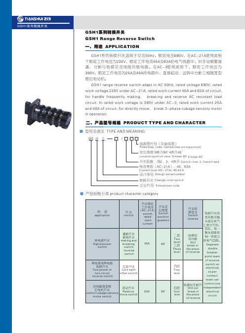
六、结构型式 STRUCTURE TYPE
本产品采用组合式结构,由定位、限位、接触系统及面板、手柄构成,接触系统为桥式双断点结构,并由各自的凸轮控制其通断。定位系统采用棘轮棘爪式结构,更换不同的定位棘轮和配以相应的凸轮,开关可获得不同的旋转角度,从而实现相应的开关状态。
通断开关(代号:TD)
Making and breaking switch (code:TD)
图()1 GSH1-40A、63A转换开关外形尺寸
Picture 2 GSH1-40A、63A Outline ion of
Picture Reverse Switch
△ 换相开关(代号:HX) Change phase switch (code: HX)
开关层数 switch level 234
H(mm)GSH1-40、6390max 111max 132max
图()2 GSH1-40A、40、63转换开关安装孔尺寸
Picture 2 GSH1-40A、40、63 reverse switch installation hole size
Picture 接线图 wiring picture
The product use modular structure, composed by positioning, spacing, contact system, panels and handle, contact system is double breakpoint bridge structure, and their cam control making and breaking. Positioning system uses ratchet pawl structure, replace different positioning ratchet and support corresponding cam, switch can reach different rotate angles, so as to achieve corresponding switch state.
GSG2
5500 750 500 250 14.5
4000 600 400 200 27
4000 600 400 200 27
3000 450 300 150 27
重量 (Kg)
3极 4极
1
1
2
2
3.5
3.5
4
4
10.5 10.5
16
1.5
250A/4 230 170 138 35 98 86 5.5 210 210 90 115 50 25 30 3.5 140 11 25 76 15
315A/3 230 240 170 50 135 110 7 210 210 140 145 65 32 40 5 206 11 37 94 20
GSG2-160~ 630/JK 柜 外 操 作
底板尺寸
I
M
Z
W
Q
60
6.5
85
190
218
60
6.5
85
190
218
60
6.5
110
220
245
60
6.5
110
220
245
60
6.5
135
240
270
60
6.5
135
240
270
500A/4 290 260 170 50 135 110 7 270 270 140 145 65 40 50 5 220 13 37 94 20
630A/3 230 260 170 50 135 110 7 210 210 140 145 65 40 50 5 220 13 37 94 20
abb-gsh200

标题:abb-gsh200
一:触器适用于建筑业和工业领域,如:电机控制、保暖和通风、空调、水泵、提升设备、照明和校正功率因数等。
ABB接触器的规格包括4和5.5KW的微型接触器、高达400kW的接触器组(AC3),建筑用接触器(家用和工业用),拍合式接触器,热过载继电器和电子继电器,以及完整的附件,确保选择灵活性和满足客户需求,公司制造工厂位于海西经济区的核心----美丽的鹭岛厦门。
二:ABB断路器可为快速恢复运行条件(防止故障发生),并提供最好的解决方案,同时可提供最优的电气安装保护。
从微型断路器到高分断能力的塑壳/空气断路器
三:小型断路器多级:ABB断路器可为快速恢复运行条件(防止故障发生),并提供最好的解决方案,同时可提供最优的电气安装保护。
从微型断路器到高分断能力的塑壳/空气断路器
四:变频器主要用于控制和调节三相交流异步电机的速度,并以其稳定的性能、丰富的组合功能、高性能的矢量控制技术、低速高转矩输出、良好的动态特性及超强的过载能力,在变频器市场占据
着重要的地位。
TKQ2 双电源自动切换开关Series Dual Power Automatic Transfer Switches
TKQ2 Series Dual Power Automatic Transfer SwitchesⅠUsing OccasionTKQ2 Series Intellectual dual power automatic transfer switches (A.T.S for short) is one of the newest scientific technology products. It is used in 50Hz, 400V AC power supplying system, with the function of automatic transfer between the normal power supply (N) and the reserved one (R), guarantee the reliability and safety of supplying power. This product is produced according to the standard of GB/T14048.00-2002、IEC60947-6-1 《Automatic Transfer Switch Electric》and 《Water-proof Norms of Tall Residential Building》, 《Fire-proof Norms of Building Design 》, 《Urgent Lighting Design Enchiridion》, 《Electric Design Norms of Residential Building》etc. It can be used widely in the places where the power cut is not allowed, such as hospital, shopping malls, bank, chemical plant, tall building, military device, fire protection etc.ⅡCharacterTKQ2 series A.T.S is different from the previous transfer switches, such as the power-load switch which combined with load-switches, transfer switches which combined with contactors. TKQ2 series A.T.S is made of two new-generation molded case circuit breakers (MCCB), which have high breaking capacity, with its own accessories; the single electricity machinery drive with mechanical interlock and intellectual controller.It has the capacity of short circuit and over-load protection; over-voltage, under-voltage, lack of phase automatic transfer function, to guarantee the electricity distribution series operating reliably. It has the following characters:1. There is a double-protection between the two circuit breakers. One is reliable mechanical interlocking mechanism; the other is the intellectual electric interlocking which core is MOTOROLA Single Chip Micyoco (SCM).2. Over-load, under-load, lacking phase automatic transfer and intellectual alarm function.3. Electricity machinery operating protection4. The parameter can be set freely at the outside.5. Small volume, easy to fit and use.6. Energy saving, no noise running.7. The switch has electric fire fighting controller. When the fire fighting center give a control signal to the auto controller, the two circuit breakers will come to the open state.8. It has the computer interface, so it has the function of remote control, remote regulation, remote communicate and remote transport.ⅢWorking Condition1. Ambient air temperature:1) Upper limit:≤+40℃2) Lower limit:≥-10℃The average temperature in 24 hours is not exceed +35℃.2. Altitude: the altitude of install place is not exceed 2000m3. Atmosphere condition: the relative humidity of the atmosphere is not exceed 50% when theambient temperature is +40℃, and the lower temperature is, the higher humidity will be. When the lowest average temperature is 25℃ in the moistest month, the highest average humidity of this month is 90%, and the dew on the switch surface is also considered for the temperature changed.Ⅳ. Model and SignificationTK Q 2rated current of circuit breakergrade frame current of circuit breaker R: self-input and self-recover S: self-input without self-recover F: utility-generator B: combineddesign sequence number dual power Automatic Transfer Switches enterprise codeⅤ SpecificationThe main specifications are listed in sheet 1, and the special types can be communicated.Ⅵ Main technology parameter1. Rated working voltage of intellectual controller: AC 230V2. The life time of the switch (N-R-N circulation) and character parameter are listed as sheet 2.Ⅶ. Externality and Installation dimensionThe picture1 and picture2 are the externality, picture3 is the divided controller panel, and the installation dimension is list in sheet3.The externality of holistic controller and installation dimension (picture1 and sheet3).Picture1The externality of divided controller and installation dimension (picture2 and sheet3).Picture2The dimension of divided controller (picture3)Picture3ⅧMain structure and the working principleTKQ3 series dual power automatic transfer switch is made of two molded case circuit breakers (MCCB), transporting structure electricity machinery with mechanical interlocks, intellectual controller etc, all the devices are installed on one panel. And the controller interior is intellectualauto controlling circuit, made of MOTOROLA single chip micyoco (SCM) and advanced, reliable electronic component.1. Working principle of auto controllerThe auto controller tests the three phases voltage of normal and reserved power supply in the same time, when the numerical is 110% higher than the rated one, the controller views it as over-voltage, 60~85% lower than the rated one is under-voltage (the user can set the specific parameter freely). The internal circuit judges the test result of the timely phase for six voltages margin. When the result passes the relay, it drives the related relay give the open and close orders to the electricity machinery operating structure. And the above test result will be showed by some LEDs on the panel. There are four working ways (“automatic and manual”, “normal power supply”, reserved power supply”, “release <reclose>”), transfer delay time and the under-voltage numerical can be set through six push button switches. The switches are installed on the panel.2. Test and control function of auto controller2.1 self-input and self-recover auto controllerTKQ2 is used for the auto transforming between the normal power supply and reserved power supply. In usual time, the power was supplied by the normal power supply, and when it become abnormal (any single phase is over-voltage, under-voltage, interrupted phase), the reserved power supply will work after the appropriate delay; when the normal power supply refined, it will work once again automatically.Make sure the reserved power supply is no damaged. When it has some abnormal situation, the related LED on the panel will turn yellow, and the internal buzzer will offer an alarming signal to tell the user to restore.The function of the self-input and self-recover auto controller (sheet 4)2.2 自投不自复式auto controllerTKQ2 is used for the auto transforming between the normal power supply and reserved power supply. In usual time, the power was supplied by the normal power supply, and when it become abnormal (any single phase is over-voltage, under-voltage, interrupted phase), the reserved power supply will work after the appropriate delay; when the normal power supply refined, it can’t work once again automatically, unless the reserved power supply has some problem. The situation is also fit for the contrary condition.Make sure the reserved power supply is no damaged. When it has some abnormal situation, therelated LED on the panel will turn yellow, and the internal buzzer will offer an alarming signal to tell the user to restore.The function of the 自投不自复式auto controller (sheet 5)2.3 power grid generating auto controllerTKQ2 is used for the auto transforming between the normal power supply and reserved power supply. In usual time, the power was supplied by the normal power supply, and when it becomes abnormal (any single phase is over-voltage, under-voltage, interrupted phase), the intellectual controller orders to release the electricity by offering a controlling request as well as a unloading order (when the generator’s capacity is limited, user can unload the unimportant section). When the generating voltage is up to 85% of the rated one, the power of power grid will be cut automatically after some delay, and after some other delays, the generating power supply will work automatically. When the normal power supply recovers, it will work automaticallyThe function of the电网发电式auto controller (sheet 6)Q N-the normal power supply’s circuit breaker closeQ R-the reserved power supply’s circuit breaker closet1- delay for open (the longest delay is 60s, the shortest is 0.5s, producing setting 1.5s)t2- delay for close (the longest delay is 60s, the shortest is 0.5s, producing setting 1.5s)3. the wiring map of the second circuit (according to the map)TKQ2-R (S.F) second circuit wiring map (100-225 type)Notice:the picture is for the reclose-open positionQ N-the normal power supply’s circuit breakerQ R-the reserved power supply’s circuit breakerR1-normal fuseR2: reserved fuseM: operating electricity machineryPG: cable joint wireK1, K2: micro switchJX: terminals (picture a: wring map for indicator lamp)JXN: special terminals for three-phase null lineFire control and alarm control are used for R.S typeGenerating control and unload order are used for F typeN (null line) must be jointed; otherwise the intellectual controller will be damaged.Users joint the circuit showed by dotted line, the others have been jointed.When need the fire control cut the power urgently, please joint the on-off signal which showed by the fire center to the intellectual controller’s terminals.picture aNormal reservedIndicator lamp joint portTKQ2-R (S.F) second circuit wiring map (400-800 type)Notice:The picture is for reclose-open position本图在再扣分闸位置Q N-the normal power supply’s circuit breakerQ R-the reserved power supply’s circuit breakerR1-normal fuseR2: reserved fuseM: operating electricity machineryPG: cable joint wireK1, K2: micro switchJX1: terminals of exterior indicative lamp (picture b)JXN: special terminals for three-phase null lineFire control and alarm control are used for R.S typeGenerating control and unload order are used for F typeN (null line) must be jointed; otherwise the intellectual controller will be damaged.Users joint the circuit showed by dotted line, the others have been jointed.When need the fire control cut the power urgently, please joint the on-off signal which showed by the fire center to the intellectual controller’s terminals.Picture bnormal normal reserved reservedIndicator lamp joint portⅨ. Installation and Regulationinstall the switchTo protect yourself and the electric device safety, please make sure to do the following things before use the ATS:read the instruction carefully before installing and using A TS.ATS must be used in the normal working condition.Check the circuit breaker, to see if their specifications are complied with the work condition before installation.Before installing, measure the insulating resistance of the circuit breakers with 500V (Katherine Ohm meter)兆欧表(please note that, when measuring the insulating resistance, please cut the second circuit lead which jointed to the circuit breaker, otherwise the auto transfer controller will be damaged). The resistance should not be less than 10MΩ when the ambient temperature is 20℃±5℃ and relative humidity is 50%~70%. Otherwise the circuit breaker must be dryinged, to make sure the insulating resistance achieve the standard require.When installing, the safety distance of ATS must be complied with GB14048.1.When installing, make sure there is no conductive abnormal things on the circuit breaker.When installing, the conductive bus bar which connected to the ATS’s circuit breaker must be smooth. No attached mechanical strength is allowed to impose on the circuit breaker, avoiding to damage them and their motion character.After install the switch, choose the leads with suitable section to joint the circuit breaer’s output and input terminals, according to the rated current. The four-pole circuit breaker can joint no lead, only to joint the input terminal. Make sure the null line must be joint correct, otherwise the intellectual controller and motor operating structure will be damaged. As for three-pole circuit breaker, there in a N line must be jointed to the N terminal on the switch body bracket.Notice: the phase of the two circuit breakers must be coincident, and the switch body must be connected to the earth reliably.2. manual control and regulation (self-input and self-recover)When the normal, reserved and controller power supply are connected, the digital tube on the top of controller panel shows two numerical value rows; phase indicative lamps (A,B,C) flash circularly; state indicative lamps (three colors) show the normal power supply green (close), reserved power supply red (open), that means the A TS works under the good condition. If the state indicate lamps are yellow, there is a fault exist in the relative circuit. (three colors of the state indicative lamp respectively means three state: close-green; open-red; fault-yellow)Press the “normal power supply” button, Q N circuit breaker close.Press the “reserved power supply”button, Q N circuit breaker open, and Q R circuit breaker will close after delay t2.Press the “normal power supply”button, Q R circuit breaker open, and Q N circuit breaker close after delay t2. then press “cut (reclose)”button, the circuit breaker will be open instantly if it is close before electrifying.Press “auto” button, it will come to the auto controlling state according to the using power supply. And the closing indicative lamp should be lighted or put out in the operating process.The released indicative lamp can be tested if necessary. Open the transfer switch’s veil after circuit breaker is close, then press the urgent released button, the released indicative lamp on the intellectual controller will be lighted after the circuit breaker is 脱扣, and it will be put out after reclosing.Notice: when a circuit breaker is 脱扣, the controller must be transferred to mutual, press “cut (reclose)” button to make the released circuit breaker reclose, then can be transferred to auto state, let the circuit close.Ⅹ. Using methodAfter the above regulating, the normal TKQ2 system can be used. Before operating, if choose “self-input and self-recover”, only to press “auto” button, the auto indicative lamp on the panel will light, and the normal power supply is the preferential supply; if choose “self-input without self-recover”, you can select any one circuit power supply to work, only to press its button.The usage of the function key:1. power supply key: cut and connect the power supply which is on the main panel.2. set key: press this key, the system can be transferred among three states: norma l→showin g→set under-voltage percentage(A-1)→set cutting delay time(A-2)→set close delay time(A-3) →showing normally3. auto key: press this key, the indicative lamp light, the system can be set at the self-input and self-recover state.4. normal power supply key: press this key, the normal power supplier offer the power to the system, and it is at the self-input without self-recover state.5. reserved power supply key: press this key, the reserved power supplier offer the power to the system, and it is at the self-input without self-recover state.6. release key: press this key, the system will be released.7. under the set state, the normal power supply key is used to add the set numeral (+key), and the reserved power supply is used for reduce the set numeral (-key).Ⅺ. Analysis and remove the faultIf no response offered when start the switch, and the mechanical interlocking driver has no motion after pressing the indicative button, please check the power supply and connection of circuit breakers. Three-phase power supply and the N line must be jointed correctly; intellectual controller socket must be screw down, well contact.When controller was power supplied, but the mechanical interlocking driver has no motion, please check the fuse of the auto controller, to see if it is burned-up for over-current of the motor operating structure. Please retry after taking another suitable fuse.The fuse is burned-up frequently, please check the mechanical interlocking driver to see if it is locked. Please retry after some adjustment.Ⅻ. Other notice:1. Check and maintain the switch termly according to the circuit breaker and mechanical interlocking driver.2. Take the intellectual controller away before testing the switch’s frequency pressure.3. If the switch is unused for a long time, it must be humidity-proof and dust-proof. Before it works, make sure regulate it as the above using method, and guarantee it can work normally.4. Specific requests please tell the manufacturer, and note them when order.5. This product has a 18 months labor warranty after outgoing. In this time, customers must regulate, use and maintain it under the set using condition. But if it is for the product quality problem, our company guarantees to mend, change, and even take it back.ⅩⅢ. Order noticeUsers must inform us the following requests:1. name and type of the dual power transfer switch2. rated current of the dual power transfer switch3. the using way of dual power transfer switch (grid-grid or grid-generator)4. installation way of the intellectual controller (combined or divided )5. if need combined fire protect motion(消防联动) , please point it out.6. quantityExample:order TKQ2-225L (three-poles) doulb-power supply auto transferred device.rated current: 220A, grid-grid, combined controller, 60 sets. The order format should be written: TKQ2-BR 2250L-220A/3PA, 60 sets.TKQ2系列双电源自动切换开关使用说明书一. 适用范围TKQ2系列智能型双电源自动切换开关(简称A.T.S)是我公司采用最新技术开发的高新科技产品,适用于交流50HZ, 400V的双电源供电系统,可以完成常用电源(N)与备用电源(R)之间的自动切换,以保证供电的可靠性和安全性.本产品符合GB/T14048.11-2002, IEC60947-6-1《自动转换开关电器》标准, 也符合《高层民用建筑防水规范》,《建设设计防火规范》,《应急照明设计指南》,《民用建筑电气设计规范等》.广泛应用于医院,商场,银行,化工,高层建筑,军事设施,消防等不允许断电的重要场合.二. 产品特点TKQ2系列的A.T.S不同于以往的电源切换开关,如由负荷开关组成的电源负荷开关,接触器组成的电源切换开关.TKQ2系列A.T.S是由两台具有高分断能力的新一代塑壳断路器和其内部附件、带机械联锁的单电机传动机构,智能化控制器等组成.具有短路、过载保护、过压、欠压、缺相自动切换功能,以保证配电系统的高可靠性运行,其特点是:1. 两台断路器之间有可靠的机械联锁机械和以MOTOROLA单片机为核心的智能电气联锁双重保护.2. 具有过压、欠压、缺相自动切换和智能报警功能.3. 具有操作电机智能保护功能.4. 参数可在外部自由设定.5. 体积小巧, 安装使用方便.6. 节能、无噪音运行.7. 本开关备有消防控制电器,当消防控制中心给一控制信号进入自动控制器,两台断路器都进入分闸状态.8. 留有与计算机联网的接口,以备实现遥控、遥调、遥信、遥传.三. 正常工作条件周围空气温度: 上限值不超过+40℃; 下限值不超过-10℃; 24小时的平均值不超过+35℃. 海拔: 安装地点的海拔不超过2000m大气条件: 大气的相对湿度在周围最高温度+40℃时不超过50%, 在较低的温度下可以有较高的湿度,在最湿月的平均最低温度+25℃时,该月的平均最大相对湿度为90%, 并考虑到因温度变化在表面上的凝露.四. 型号及含义五. 产品规格主要规格如表1所示,特殊要求可协商供货.表1六. 主要技术参数智能控制器的额定工作电压为AC230V开关的使用寿命(N-R-N循环)及性能参数见表2.七. 外形和安装尺寸外形见图1、图2, 分体式控制器面板见图3,安装尺寸见表3. 整体式外形与安装尺寸图(见图1和表3)图1分体式外形与安装尺寸图(见图2和表3) 图2分体式控制器尺寸图(见图3)图3八. 主要结构和工作原理TKQ2双电源自动切换开关由两台塑壳断路器,带机械联锁电机传动机构、智能化控制器等组成,所有器件安装在一块金属底板上,控制器内部采用MOTOROLA单片机和先进可靠的电子元器件组成的智能化自动控制电路.1.自动控制器的工作原理简述如下:自动控制器对常用电源和备用电源的三相电同时进行检测,高于额定值的110%即判为过电压,低于60~85%(具体参数由用户自行设定)则按欠压处理.内部电路对六个电压幅值及进性相位的检测结果进行判断,处理结果通过延时后,驱动相应的指令继电器向电动操作机构发出分闸、合闸指令.上述检测结果同时用若干个发光二极管在面板上显示.通过面板上的六个按钮开关可以设定四种工作模式(“自动手动”、“常用电源”、“备用电源”、“脱扣(再扣)”)、转换延时时间及欠电压值.2.自动控制器的检测与控制功能如下:自投自复式自动控制器TKQ2用于常用电源和备用电源之间的自动切换.平时由常用电源供电,当常用电源发生异常(任一相电压过电压、欠电压、断相)时,经适当延时切换到备用电源供电;当常用电源恢复正常后,则又自动返回换接到正常电源供电.备用电源平时必须正常完好,当备用电源出现异常时,自动控制器面板上对应的发光二极管变成黄色,并由内部蜂鸣器向外部发出报警信号,提醒用户必须立即修复.自投自复式自动控制器的功能见表4表4TKQ2用于常用电源和备用电源之间的自动切换.平时由常用电源供电,当常用电源发生异常(任一相电压过电压、欠电压、断相)时,经适当延时切换到备用电源供电;当常用电源恢复正常后,不能自动返回换接到正常电源供电;除非备用电源出现异常才进行切换,反之亦然.备用电源平时必须正常完好,当备用电源出现异常时,自动控制器面板上对应的发光二极管变成黄色,并由内部蜂鸣器向外部发出报警信号,提醒用户必须立即修复.自投不自复式自动控制器的功能见表5电网发电式自动控制器TKQ2用于常用电源和备用电源之间的自动切换.平时由常用电源供电,当常用电源发生异常(任一相电压过电压、欠电压、断相)时,智能控制器发出发电控制指令请求发电,并发出卸载指令(在发电机容量不够时,由用户选择卸去部分非重要负载),当发电电压达到额定电压的85%时,经一定的延时后自动切断电网电源,再经延时自动切换到发电电源供电;当常用电源恢复正常后,则又自动返回换接到正常电源供电.电网发电式自动控制器的功能见表6表6注:Q N合表示常用电源的断路器合闸;Q R分表示备用电源的断路器分闸;t1: 分闸延时(最长延时60秒,最短延时0.5秒,出厂整定1.5秒)t2: 合闸延时(最长延时60秒,最短延时0.5秒,出厂整定1.5秒)3. 二次回路接线图(见图)TKQ2-R(S.F)二次回路接线图(100-225型)注: 本图在再扣分闸位置Q N: 常用电源断路器JX: 接线端子(指示灯接线见图形a)Q R: 备用电源断路器JXN: 三极零线专用端子R1: 常用保险丝消防控制、报警信号用于R.S型R2: 备用保险丝发电控制、卸载指令用于F型M: 操作电机N中线必须接妥,否则会对智能控制器造成损害PG: 电缆连接线虚线中由用户连接,其它导线已接好K1、K2: 微动开关需要消防控制紧急断电时,请将消控中心输出的开关信号接入智能控制器的端子.100-225型指示灯接线端图aTKQ2-R(S.F)二次回路接线图(400-800型)注: 本图在再扣分闸位置Q N: 常用电源断路器JX1: 外接指示灯接线端子(见图b)Q R: 备用电源断路器JXN: 三极零线专用端子R1: 常用保险丝消防控制、报警信号用于R.S型R2: 备用保险丝发电控制、卸载指令用于F型M: 操作电机N中线必须接妥,否则会对智能控制器造成损害PG: 电缆连接线虚线中由用户连接,其它导线已接好K1、K2: 微动开关需要消防控制紧急断电时,请将消控中心输出的开关信号接入智能控制器的端子.400-800型指示灯接线端图b九. 安装与调整1.开关的安装为了保证您的人身安全及电气设备的安全,A TS在投入运行前,请用户务必做到:1)ATS在安装使用前必须认真阅读本使用说明书2)ATS必须在正常工作条件下投入使用3)安装前先检查ATS上使用的断路器规格是否符合使用要求4)安装前先用500V兆欧表测量A TS上使用的断路器的绝缘电阻(请注意:测量绝缘电阻时,应断开连在断路器上的二次回路导线,否则将会损坏自动切换控制器),在周围空气温度20℃±5℃和相对湿度50%~70%下应不小于10MΩ. 否则断路器必须烘干,待绝缘电阻达到规定要求后方能使用.5)安装时,ATS的安全距离应符合GB14048.1国家标准6)安装时,请注意不能有导电的异物落入A TS上的断路器上7)安装时,与ATS上的断路器连接的导电母线,在连接时应平整,不能有附加的机械应力强制在断路器上,以免损坏断路器及动作特征.8)开关安装后,应根据额定电流的大小选用合适截面积的导线将断路器的输入、输出端子接好.对于四极断路器不必再另外接线,只要将断路器输入端子接妥,整个TKQ2的工作电源就接好了.但是必须注意,N线不能接错,否则将会烧坏智能控制器及电动操作机构.对于三极断路器则还需加一根N线到开关本体支架的N端子上.注意: 两个断路器输入端子的相序必须一致,开关本体的保护接地可靠接妥.2. 手动控制器调试(以自投自复为例)接通常用电源和备用电源及控制器电源,此时控制器面板上部的数码管显示两组数值;相位指示灯(A、B、C)循环闪烁;状态指示灯(三色)显示常用电源为绿色(合闸),备用电源为红色(分闸),表示智能控制器检测到六相电压均在正常范围内,A TS正常工作.若状态指示灯显示为黄色,则表明该路电源故障.(注:状态指示灯的三种颜色分别对应三种状态: a 合闸-绿色; b 分闸-红色; c 故障-黄色; 后面的说明里不再提示灯的颜色变化,请用户仔细对照) 按一下“常用电源”按钮, QN断路器合闸按一下“备用电源”按钮,QN断路器分闸,经t2延时后QR断路器合闸再按一下“常用电源”按钮,QR断路器分闸,经t2延时后QN断路器合闸.按一下“断电(再扣)”按钮,如果通电前有某个断路器处于合闸位置,则该断路器立即分闸.按一下“自动”按钮,则根据当时使用的电源进入自动控制状态.上述操作过程中合闸指示灯应正确的点亮或熄灭.必须时还可以作脱扣指示灯的测试,即断路器合闸后打开切换开关的面罩,按下该断路器的紧急脱扣按钮,断路器脱扣后智能控制器上的脱扣报警指示灯应点亮,再扣后指示灯熄灭.注意: 当一台断路器脱扣后,必须将控制器上的功能转换至手动状态,操作“断电(再扣)”按钮,使脱扣的断路器再扣,然后才可转换至自动状态将断路器合闸.十使用方法经过上述调试,工作正常的TKQ2系统即可投入使用.正式投入使用前,若是选择自投自复状态,则须按下“自动”键,面板上自动指示灯点亮,这是常用电源是优先电源;若是选择自投不自复状态,则可以选择一路电源供电,按一下该电路电源的按钮即可.功能键用途如下:1电源键: 此键可切断和打开主控板供电电源.2设定键: 按下此键,可依次使系统在三个状态之间切换正常---显示----设定欠压百分比(A-1)----设定切断延时时间(A-2)----设定合闸延时时间(A-3)----正常显示.3自动键: 按下此键,指示灯亮,可使系统设定在自投自复状态.4常用电源键: 按下此键,可使系统切换在常用电源供电,并使系统设定在自投不自复状态. 5备用电源键: 按下此键,可使系统切换在备用电源供电,并使系统设定在自投不自复状态. 6脱扣键: 按下此键,使系统供电脱扣.7在设定状态下, 常用电源用来加大设定值(+键)备用电源用来减少设定值(-键)十一故障分析与排除开机后无反应,按指令按钮后机械连锁传动机构不动作,请检查断路器的电源及接线情况.三相电源及中性线必须接妥,智能控制器上的接插件应插紧拧牢,接触良好.通电后控制器有电,但机械连锁传动机构不动作时,请检查自动控制器上的熔丝管是否因电动机构电流太大而烧毁.用合适的熔丝管更换后再试.经常烧毁熔丝请检查机械连锁传动机构是否有卡死现象,适当调整后再试.十二其他注意事项应根据所选用的断路器及机械连锁传动机构的要求定期检查与保养.若要求对开关进行工频耐压实验,请将智能控制器脱离后进行/长期不使用的产品应注意防潮,防尘,在使用前应按前述内容进行调试.正常动作后方可投入进行.用户如有特殊要求,请与制造商联系,并在定货时说明.本产品自出厂之日起18个月内实行保修,保修期内用户按本产品规定使用要求进行调整,使用与维护保养,但因产品本身质量问题而无法使用时,本厂负责修理,更换甚至退货.十三定货须知用户定货时必须说明:a)双电源切换装置的名称及型号;b)双电源切换装置的额定电流(A)c)双电源切换装置的使用方式(电网-电网或电网-发电机);d)智能型控制器的安装方式(连体式或分体式);e)若需消防联动,请说明f)数量.例: 订购TKQ2---225L(三级) 双电源自动切换装置, 额定电流200A, 电网-电网,控制器为联体式, 60台,应写为:TKQ2 B R 225L---200A/33PA 60台.。
- 1、下载文档前请自行甄别文档内容的完整性,平台不提供额外的编辑、内容补充、找答案等附加服务。
- 2、"仅部分预览"的文档,不可在线预览部分如存在完整性等问题,可反馈申请退款(可完整预览的文档不适用该条件!)。
- 3、如文档侵犯您的权益,请联系客服反馈,我们会尽快为您处理(人工客服工作时间:9:00-18:30)。
电流等级 Current level
设计序号 Design serial number
转换开关 Reverse Switch
企业代号 Enterprises code
■ 注(Note): △ 定位角度代号为:3(30°) ;4(45°);6 (60°);9 (90°)。转动档位数、定位角
度及操作方式代号分别见“操动器位置代号及对应组合图”;其中定位型产品 操作方式位为空。 Location point of view, code-named: 4(45°) ;6 (60°) ;9 (90°). Median of rotating file, location point of view and operation code respectively "parade actuators corresponding combination code and location of the map"; one-
△ 安装地点海拔高度不超过2000米。 Elevation≤2000m.
四、型号规格说明 MECHANICAL LIFE AND ELECTRICAL LIFE
G S H 2 - □/□ □ □/□/□
操作方式 Operation 接点图编号 Contact plan No. 定位角度 The stable place of angle 转动档位数 The rotate grade of digit 开关层数 Switch-rise
GSH2系列转换开关
GSH2系列转换开关 GSH2 Range Reverse Switch
一、用途 APPLICATION
GSH2转 换 开 关 主 要 用 于 交 流 50Hz、 额 定 工 作 电 压 400V以 下 , 直 流 电 压 2 3 0 V以 下 , 供 手 动 不 频 繁 接 通 、 分 断 或 转 换 交 流 直 流 负 载 电 路 , 也 可 以 直 接 控 制 三相异 步 电 动 机或作 主 令 电 路 控 制 用,大 规 格 转 换 开 关 后 端 可 加 小 电 流 转 换 开 关,做辅助开关。
产品符合标准GB 14048.3 及IEC 60947-3 Products meet the standard GB 14048.3 and IEC 60947-3 二、工作条件 WORK CONDITION
△ 周围空气温度不超过+40℃,不低于-5℃ ,24小时平均温度不超过+35℃。 Ambient temperature: -5℃~+40℃, average temperature ≤+35℃ in 24H;
△ 最高温度为+40℃时,空气的相对湿度不超过50%,在较低温度下可允许有较高 的相对湿度。对于温度偶尔产生的凝露现象,应采取特殊的措施。 Relative humidity is not exceeding 50% at the maximum ambient temperature 40℃ . With lower temperature, higher humidity would be permitted. Should give consideration to the dews on the goods surface, which would appear due to temperature change.
GSH2 switch for the exchange of 50Hz, rated voltage 400V below, the following 230V DC voltage for frequent manual does not get through, breaking the conversion or exchange of load DC Circuit, directly and asynchronous motor control of the three main control circuit , The standard back-end switch may be a small current change-over switch, do auxiliary switch.
GSH2系列转换开关pr源自duct operation targeting empty spaces; △ 接点图编号见节点图举例,其编号规则:
Figure contact numbers see map, for example, the number of its rules: A.接点图用4位数字表示。Figure contact numbers said 4-digit. B.数字的第一位含义:1表示UPS中使用;2表示多档开关(双掷、三档、四档、 五 档 、 步 进 和 调 档 ) ;3表 示 电 动 机 中 使 用 ;4表 示 电 压 、 电 流 测 量 用 ;5表 示 电 容柜中使用;9表示其它。 The first meaning of the figures: 1, said the use of UPS; that more than 2 file switch (double throw, third gear, fourth gear, five gear, stepping and gear shift); 3 that the use of electric motors; 4, said voltage and current measurement use; 5 counter that the use of capacitor; 9, said other. C .后3位 数 用 流 水 号 表 示 , 每 一 种 接 点 时 序 一 个 流 水 号 ( 多 档 开 关 的 流 水 号 规 则 可参照节点图)。 After the 3-digit serial number with that of a timing point of each serial number (serial number of multi-profile switch node in the light of the rules can map). △ 操作方式:① 定位型;② 自复型;③ 定位自复型; Operation: ①location; ② self-rehabilitation; ③ location self-rehabilitation △ 定位型有1-8节,自复型有1-3节,直接控制电动机用有1-6节。 Locations are 1-8 section, self-rehabilitation are1-3 section, the direct control of motors are 1-6 section.
