1N5400GP中文资料
1N5400-1N5408整流二极管中文资料
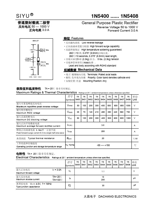
1.1V 1N 54011N 54021N 54031N 54041N 54051N 54061N 54071020030μA pF1N5400 ...... 1N54081N 54081N 5400SIYUR极限值和温度特性 TA = 25℃ 除非另有规定。
普通塑封整流二极管反向电压 50 --- 1000 V正向电流 3.0 AGeneral Purpose Plastic RectifierReverse Voltage 50 to 1000 VForward Current 3.0 AI RCj最大正向电压 I F = 3.0A最大反向电流 TA= 25℃典型结电容 V R = 4.0V, f = 1MHzMaximum forward voltageMaximum reverse current Type junction capacitanceV F符号Symbols 单位Unit电特性 TA = 25℃ 除非另有规定。
Electrical Characteristics Ratings at 25℃ ambient temperature unless otherwise specified.TA=100℃ 大昌电子 DACHANG ELECTRONICS特征 Features·反向漏电流低 Low reverse leakage·正向浪涌承受能力较强 High forward surge capability·高温焊接保证 High temperature soldering guaranteed:260℃/10 秒, 0.375" (9.5mm)引线长度。
260℃/10 seconds, 0.375" (9.5mm) lead length,·引线可承受5 磅 (2.3kg) 拉力。
5 lbs. (2.3kg) tension 机械数据 Mechanical Data·端子: 镀锡轴向引线 Terminals: Plated axial leads·极性: 色环端为负极 Polarity: Color band denotes cathode end ·安装位置: 任意 Mounting Position: Any·引线和管体皆符合ROHS标准 。
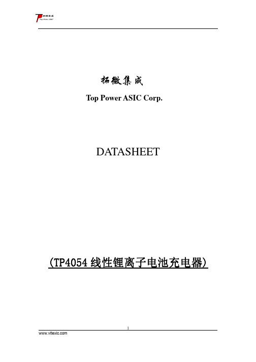
TP4054中文手册_替代LTC4054
0.8
1.8
4
ms
IPROG
PROG 引脚上拉电流
2.5
μA
3
南京拓微集成电路有限公司
典型性能特征
恒定电流模式下 PROG 引脚 电压与电源电压的关系曲线
PROG 引脚电压与温度的 关系曲线
充电电流与 PROG 引脚电 压的关系曲线
PROG 引脚上拉电流与温度 和电源电压的关系曲线
PROG 引脚电流与 PROG 引脚 电压的关系曲线(上拉电流)
1000V
1000V
R=
PROG
I
, ICHG = R
CHG
PROG
从 BAT 引 脚 输 出 的 充 电 电 流 可 通 过 监 视 PROG 引脚电压随时确定,公式如下:
V
I BAT
=
PROG
R
• 1000
PROG
至设定值的 1/10 时,充电循环被终止。该条
件是通过采用一个内部滤波比较器对 PROG
在电池的充电过程中,由一个内部 N 沟道
MOSFET 将 CHRG 引脚拉至低电平。当充
电循环结束时,一个约 20μA 的弱下拉电流
源被连接至 CHRG 引脚,指示一个“AC 存
在”状态。当 TP4054 检测到一个欠压闭锁
条件时,CHRG 引脚被强制为高阻抗状态。
GND(引脚 2):地 BAT(引脚 3):充电电流输出。该引脚向电 池提供充电电流并将最终浮充电压调节至 4.2V。该、引脚的一个精准内部电阻分压器 设定浮充电压,在停机模式中,该内部电阻 分压器断开。 VCC(引脚 4):正输入电源电压。该引脚向 充电器供电。VCC 的变化范围在 4.25V 至 6.5V 之间,并应通过至少一个 1μF 电容器 进行旁路。当 VCC 降至 BAT 引脚电压的 30mV 以内,TP4054 进入停机模式,从而使
PLG微型热敏打印机开发手册V1.3
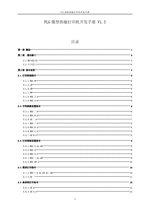
PLG微型热敏打印机开发手册V1.3目录第一章概述----------------------------------------------------------------------------------------1第二章通讯接口-----------------------------------------------------------------------------------22.1RS-232接口--------------------------------------------------------------------------------22.2红外接口-----------------------------------------------------------------------------------3第三章指令说明------------------------------------------------------------------------------------43.1打印控制指令-----------------------------------------------------------------------------------53.1.1ESC@------------------------------------------------------------------------------------53.1.2LF---------------------------------------------------------------------------------------53.1.3CR---------------------------------------------------------------------------------------53.1.4FF---------------------------------------------------------------------------------------53.1.5ESC J n----------------------------------------------------------------------------------63.1.6ESC d n----------------------------------------------------------------------------------6 3.2字符参数设置指令-------------------------------------------------------------------------------63.2.1ESC!N----------------------------------------------------------------------------------63.2.2ESC M n----------------------------------------------------------------------------------73.2.3GS!n-----------------------------------------------------------------------------------73.2.4ESC-n----------------------------------------------------------------------------------83.2.5ESC E n----------------------------------------------------------------------------------83.2.6ESC G n----------------------------------------------------------------------------------83.2.7GS B n-----------------------------------------------------------------------------------8 3.3打印排版设置指令-------------------------------------------------------------------------------93.3.1ESC$nL nH------------------------------------------------------------------------------93.3.2ESC2------------------------------------------------------------------------------------93.3.3ESC3n----------------------------------------------------------------------------------93.3.4ESC\nL nH------------------------------------------------------------------------------93.3.5ESC SP n--------------------------------------------------------------------------------10 3.4图形打印指令----------------------------------------------------------------------------------103.4.1ESC*m nL nH d1…dk--------------------------------------------------------------------103.4.2GS'------------------------------------------------------------------------------------11 3.5条形码打印命令--------------------------------------------------------------------------------123.5.1GS k------------------------------------------------------------------------------------123.5.2GS h n----------------------------------------------------------------------------------123.5.3GS w n----------------------------------------------------------------------------------123.5.4GS H n----------------------------------------------------------------------------------133.5.5GS f n----------------------------------------------------------------------------------13 3.6汉字打印指令----------------------------------------------------------------------------------133.6.1FS&------------------------------------------------------------------------------------143.6.2FS.------------------------------------------------------------------------------------14附录----------------------------------------------------------------------------------------------15 A英文字符集-----------------------------------------------------------------------------15 B预印刷黑标说明-------------------------------------------------------------------------15第一章概述PLG微型热敏打印机是一款便携式热敏打印机,使用可充电电池供电,可带机充电,使用RS-232接口和IrDA红外接口,可用于各种仪器仪表、手持设备的数据打印。
6MBI225U-120中文资料
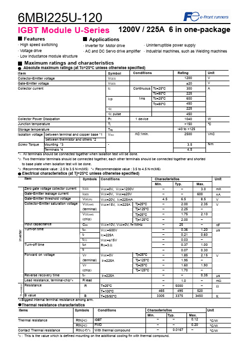
6MBI225U-1201200V / 225A 6 in one-packageFeatures· High speed switching· Voltage drive· Low inductance module structureApplications · Inverter for Motor drive· AC and DC Servo drive amplifierMaximum ratings and characteristicsThermal resistance characteristicsThermal resistanceContact Thermal resistance––0.12––0.20–0.0167 –IGBTFWDWith thermal compound°C/W°C/W°C/W*2 : Two thermistor terminals should be connected together, each other terminals should be connected together and shortedto base plate when isolation test will be done.*3 :Recommendable value : 2.5 to 3.5 N·m(M5) *4 :Recommendable value : 3.5 to 4.5 N·m(M6)Rth(j-c)Rth(j-c)Rth(c-f)*5IGBT Module U-Series*5 : This is the value which is defined mounting on the additional cooling fin with thermal compound.4Items Symbols Conditions Characteristics UnitMin.Typ. Max.· Uninterruptible power supply· Industrial machines, such as Welding machinesCharacteristics (Representative)VGE=0V, f= 1MHz, Tj= 25°CVcc=600V, I=225A, Tj= 25°CCollector current vs. Collector-Emitter voltage (typ.)Tj= 125°C / chipCapacitance vs. Collector-Emitter voltage (typ.)Dynamic Gate charge (typ.)Collector current vs. Collector-Emitter voltage (typ.)Tj= 25°C / chipCollector current vs. Collector-Emitter voltage (typ.)VGE=15V / chipTj=25°C / chipCollector-Emitter voltage vs. Gate-Emitter voltage (typ.)010020030040050060012345C o l l e c t o r c u r r e n t : I c [A ]VGE=20V15V12V10V8V010020030040050060012345C o l l e c t o r c u r r e n t : I c [A ]VGE=20V 15V12V10V8V010020030040050060001234C o l l e c t o r c u r r e n t : I c [A ]Tj=125°CTj=25°C246810510152025C o l l e c t o r - E m i t t e r v o l t a g e : V C E [ V ]Ic=450A Ic=225A Ic= 112.5A0.11.010.0100.0102030C a p a c i t a n c e : C i e s , C o e s , C r e s [ n F ]200400600800100012001400C o l l e c t o r -E m i t t e r v o l t a g e : V C E [ 200V /d i v ]G a t e - E m i t t e r v o l t a g e : V G E [ 5V /d i v]Vcc=600V, Ic=225A, VGE=±15V, Tj= 25°CStray inductance <= 100nHSwitching loss vs. Collector current (typ.)Vcc=600V, VGE=±15V, Rg=3ΩVcc=600V, Ic=225A, VGE=±15V, Tj= 125°C+VGE=15V,-VGE <= 15V, RG >= 3Ω ,Tj <= 125°CSwitching time vs. Collector current (typ.)Vcc=600V, VGE=±15V, Rg=3Ω, Tj=125°CSwitching time vs. Gate resistance (typ.)Switching time vs. Collector current (typ.)Vcc=600V, VGE=±15V, Rg=3Ω, Tj= 25°CReverse bias safe operating area (max.)Switching loss vs. Gate resistance (typ.)10100100010000100200300400S w i t c h i n g t i m e : t o n , t r , t o f f , t f [ n s e c ]Collector current : Ic [ A ]10100100010000100200300400S w i t c h i n g t i m e : t o n , t r , t o f f , t f [ n s e c ]Collector current : Ic [ A ]10100100010000110100S w i t c h i n g t i m e : t o n , t r , t o f f , t f [ n s e c ]Gate resistance : Rg [ Ω ]trtftoffton 01020304050100200300400500S w i t c h i n g l o s s : E o n , E o f f , E r r [ m J /p u l s e ]Collector current : Ic [ A ]Eon(125°C)Eon(25°C)Eoff(125°C)Err(125°C)Err(25°C)Eoff(25°C)0255075100125150110100S w i t c h i n g l o s s : E o n , E o f f , E r r [ m J /p u l s e ]Gate resistance : Rg [ Ω ]EoffErrEon0100200300400500600200400600800100012001400C o l l e c t o r c u r r e n t : I c [ A ]Collector - Emitter voltage : VCE [ V ]Transient thermal resistance (max.)Reverse recovery characteristics (typ.)Vcc=600V, VGE=±15V, Rg=3ΩForward current vs. Forward on voltage (typ.)chipTemperature characteristic (typ.)01002003004005006001234F o r w a r d c u r r e n t : I F [ A ]Forward on voltage : VF [ V ]Tj=125°CTj=25°C101001000100200300400500R e v e r s e r e c o v e r y c u r r e n t : I r r [ A ]R e v e r s e r e c o v e r y t i m e : t r r [ n s e c ]Forward current : IF [ A ]Irr (125°C)Irr (25°C)trr (125°C)trr (25°C)0.0010.0100.1001.0000.0010.0100.1001.000T h e r m a l r e s i s t a n s e : R t h (j -c ) [ °C /W ]Pulse width : Pw [ sec ]0.1110100-60-40-20020406080100120140160180Temperature [°C ]R e s i s t a n c e : R [ k Ω ]Outline Drawings, mmM6296MBI225U-120IGBT ModuleEquivalent Circuit Schematic[Thermister]135111210987246[Inverter]。
PG5404中文资料

PG5400 THRU PG5408GLASS PASSIVA TED JUNCTION PLASTIC RECTIFIER VOLTAGE - 50 to 1000 Volts CURRENT - 3.0 AmperesFEATURESl Plastic package has Underwriters Laboratory Flammability Classification 94V-O utilizing Flame Retardant Epoxy Molding Compoundl Glass passivated junction in DO-201AD packagel 3.0 ampere operation at T A =55¢J with no thermal runaway l Exceeds environmental standards of MIL-S-19500/228l Low reverse leakage current MECHANICAL DA TA Case: Molded plasticTerminals: Axial leads, solderable per MIL-STD-202, Method 208Mounting Position: Any Weight: 0.04 ounce, 1.1 gramMAXIMUM RA TINGS AND ELECTRICAL CHARACTERISTICS Ratings at 25¢J ambient temperature unless otherwise specified.Single phase, half wave, 60 Hz, resistive or inductive load.For capacitive load, derate current by 20%.PG5400PG5401PG5402PG5404PG5406PG5407PG5408UNITSMaximum Recurrent Peak Reverse Voltage501002004006008001000V Maximum RMS Voltage3570140280420560700V Maximum DC Blocking Voltage501002004006008001000V Maximum Average Forward Rectified Current .375"(9.5mm) lead length at T A =55¢J3.0APeak Forward Surge Current, 8.3ms single half sine-wave superimposed on rated load(JEDEC method)150A Maximum Forward Voltage at 3.0A1.2V Maximum Reverse Current at T a =25¢J At Rated DC Blocking Voltage T a =100¢J5.0100£g A £g A Typical Junction capacitance (Note 1)30P F Typical Thermal Resistance R £K JA(Note 2)20¢J /W Typical Reverse Recovery Time(Note 3)2£g S Operating and Storage T emperature Range T A-55 to +150¢JNOTES:1. Measured at 1 MHz and applied reverse voltage of 4.0 VDC2. Thermal resistance from junction to ambient and from junction to lead at 0.375”(9.5mm) lead length P.C.B mounted3. Reverse Recovery T est Conditions: I F =.5A, I R =1A, Irr=2.5ADO-201ADRATING AND CHARACTERISTIC CURVES PG5400 THRU PG5408PERCENT OF RATED PEAK REVERSE VOLTAGEAMBIENT TEMPERATURE, ¢JFig. 1-TYPICAL REVERSE CHARACTERISTICS Fig. 2-FORWARD DERATING CURVEAMBIENT TEMPERATURE, ¢JMAXIMUM FORWARD VOLTAGE-VFM(VpK)Fig. 3-FORWARD CURRENT DERATING CURVE Fig. 4-TYPICAL JUNCTION CAPACITANCENO. OF CYCLES AT 60HzFig. 5-MAXIMUM OVERLOAD SURGE CURRENT。
1n5408中文资料_数据手册_参数
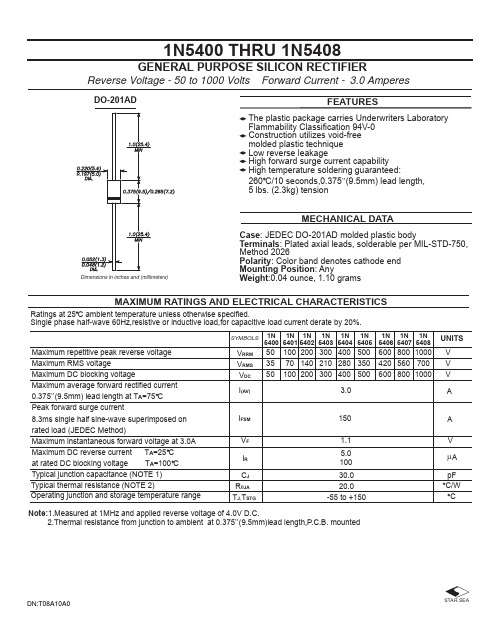
Dimensions in inches and (millimeters)
MECHANICAL DATA
Case: JEDEC DO-201AD molded plastic body Terminals: Plated axial leads, solderable per MIL-STD-750, Method 2026 Polarity: Color band denotes cathode end Mounting Position: Any Weight:0.04 ounce, 1.10 grams
DN:T08A10A0
STAR SEA
万联芯城-电子元器件采购网,提供一站式配套, 解决物料烦恼,万联芯城-以良心做好良芯,专为终端工厂企业客户 提供电子元器件一站式配套报价服务,客户提交物料清单,商城即可 整单报价,整单下单有优惠,客户整单采购可节约采购时间,节省采购 成本,万联芯城产品体系能够满足多种电子元器件物料需求, 点击进入万联芯城。
150
120
90
60
30 8.3ms SINGLE HALF SINE-WAVE (JEDEC Method)
0
1
10
100
NUMBER OF CYCLES AT 60 Hz
FIG. 4-TYPICAL REVERSE CHARACTERISTICS
1,000
100 TJ=150 C
10 TJ=100 C
10
1
0.1
1.0
10
100
REVERSE VOLTAGE,VOLTS
皮拉尼真空计_PGD400中文说明书
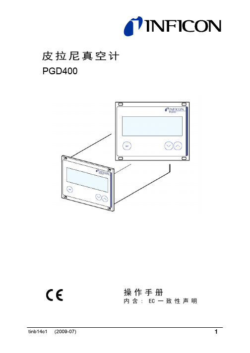
PGD400
tinb14c1 (2009-07)
操作手册
内 含 : EC 一 致 性 声 明
1
产品标识
与 INFICON 公司联系时,请告知产品标牌上的信息。为便于参考, 请将产品信息记录在以下的空格中。
PGD400 Made in China
100-240V 50/60Hz 30VA
关闭PGD400真空计 电源开关拨至OFF将 PGD400真空计电源关闭 (如仪器安装在控制柜机架上, 应通过中央配电箱开关)。
在再次启动 PGD400 电源前,至少等待 10 秒钟 仪器本机初始化。
tinb14c1 (2009-07)
19
4.3 运行模式
PGD400真空计工作于下列运行模式:
• 测量模式 用于显示测量值或状态信息 (→ 21)
测量模式
参数模式
单位
电源 on
>5 秒
阈值
22
tinb14c1 (2009-07)
选择参数 设置参数值
参数的名称 例如:
(单位) 按下键或至少1 秒钟后显示, 接着,显示当前有效的参数值。
按键 <1 秒: 值增大 / 减小 1; 按键 >1 秒: 值连续增大 / 减小;
保存修改的参数值;
tinb14c1 (2009-07)
必须不超过允许的 最高室温 (→ 9) 并具备良好的通风。
为降低面板上的机械应力,应在适当位置对仪器进行支撑。 将 PGD400 滑入控制柜的开口中 …
… 接着用四个 M3 或等效的螺丝进行紧固。
tinb14c1 (2009-07)
13
3.2 电源连接
危险
危险: 线电压 确保产品已经安全接地,否则出现故障是十分危 险的.仅推荐使用带保护接地的 3 芯电源电缆 (3×1.5 毫米2)。 电源线插头必须插入带保护接地的插座中,不能使 用无保护接地的延伸电缆。
74系列芯片功能大全

74系列芯片功能大全74系列芯片功能大全7400 2输入端四与非门7401 集电极开路2输入端四与非门7402 2输入端四或非门7403 集电极开路2输入端四与非门7404 六反相器7405 集电极开路六反相器7406 集电极开路六反相高压驱动器7407 集电极开路六正相高压驱动器7408 2输入端四与门7409 集电极开路2输入端四与门7410 3输入端3与非门74107 带清除主从双J-K触发器74109 带预置清除正触发双J-K触发器7411 3输入端3与门74112 带预置清除负触发双J-K触发器7412 开路输出3输入端三与非门74121 单稳态多谐振荡器74122 可再触发单稳态多谐振荡器74123 双可再触发单稳态多谐振荡器74125 三态输出高有效四总线缓冲门74126 三态输出低有效四总线缓冲门7413 4输入端双与非施密特触发器74132 2输入端四与非施密特触发器74133 13输入端与非门74136 四异或门74138 3-8线译码器/复工器74139 双2-4线译码器/复工器7414 六反相施密特触发器74145 BCD—十进制译码/驱动器7415 开路输出3输入端三与门74150 16选1数据选择/多路开关74151 8选1数据选择器74153 双4选1数据选择器74154 4线—16线译码器74155 图腾柱输出译码器/分配器74156 开路输出译码器/分配器74157 同相输出四2选1数据选择器74158 反相输出四2选1数据选择器7416 开路输出六反相缓冲/驱动器74160 可预置BCD异步清除计数器74161 可予制四位二进制异步清除计数器74162 可预置BCD同步清除计数器74163 可予制四位二进制同步清除计数器74164 八位串行入/并行输出移位寄存器74165 八位并行入/串行输出移位寄存器74166 八位并入/串出移位寄存器74169 二进制四位加/减同步计数器7417 开路输出六同相缓冲/驱动器74170 开路输出4×4寄存器堆74173 三态输出四位D型寄存器74174 带公共时钟和复位六D触发器74175 带公共时钟和复位四D触发器74180 9位奇数/偶数发生器/校验器74181 算术逻辑单元/函数发生器74185 二进制—BCD代码转换器74190 BCD同步加/减计数器74191 二进制同步可逆计数器74192 可预置BCD双时钟可逆计数器74193 可预置四位二进制双时钟可逆计数器74194 四位双向通用移位寄存器74195 四位并行通道移位寄存器74196 十进制/二-十进制可预置计数锁存器74197 二进制可预置锁存器/计数器7420 4输入端双与非门7421 4输入端双与门7422 开路输出4输入端双与非门74221 双/单稳态多谐振荡器74240 八反相三态缓冲器/线驱动器74241 八同相三态缓冲器/线驱动器74243 四同相三态总线收发器74244 八同相三态缓冲器/线驱动器74245 八同相三态总线收发器74247 BCD—7段15V输出译码/驱动器74248 BCD—7段译码/升压输出驱动器74249 BCD—7段译码/开路输出驱动器74251 三态输出8选1数据选择器/复工器74253 三态输出双4选1数据选择器/复工器74256 双四位可寻址锁存器74257 三态原码四2选1数据选择器/复工器74258 三态反码四2选1数据选择器/复工器74259 八位可寻址锁存器/3-8线译码器7426 2输入端高压接口四与非门74260 5输入端双或非门74266 2输入端四异或非门7427 3输入端三或非门74273 带公共时钟复位八D触发器74279 四图腾柱输出S-R锁存器7428 2输入端四或非门缓冲器74283 4位二进制全加器74290 二/五分频十进制计数器74293 二/八分频四位二进制计数器74295 四位双向通用移位寄存器74298 四2输入多路带存贮开关74299 三态输出八位通用移位寄存器7430 8输入端与非门7432 2输入端四或门74322 带符号扩展端八位移位寄存器74323 三态输出八位双向移位/存贮寄存器7433 开路输出2输入端四或非缓冲器74347 BCD—7段译码器/驱动器74352 双4选1数据选择器/复工器74353 三态输出双4选1数据选择器/复工器74365 门使能输入三态输出六同相线驱动器74365 门使能输入三态输出六同相线驱动器74366 门使能输入三态输出六反相线驱动器74367 4/2线使能输入三态六同相线驱动器74368 4/2线使能输入三态六反相线驱动器7437 开路输出2输入端四与非缓冲器74373 三态同相八D锁存器74374 三态反相八D锁存器74375 4位双稳态锁存器74377 单边输出公共使能八D锁存器74378 单边输出公共使能六D锁存器74379 双边输出公共使能四D锁存器7438 开路输出2输入端四与非缓冲器74380 多功能八进制寄存器7439 开路输出2输入端四与非缓冲器74390 双十进制计数器74393 双四位二进制计数器7440 4输入端双与非缓冲器7442 BCD—十进制代码转换器74352 双4选1数据选择器/复工器74353 三态输出双4选1数据选择器/复工器74365 门使能输入三态输出六同相线驱动器74366 门使能输入三态输出六反相线驱动器74367 4/2线使能输入三态六同相线驱动器74368 4/2线使能输入三态六反相线驱动器7437 开路输出2输入端四与非缓冲器74373 三态同相八D锁存器74374 三态反相八D锁存器74375 4位双稳态锁存器74377 单边输出公共使能八D锁存器74378 单边输出公共使能六D锁存器74379 双边输出公共使能四D锁存器7438 开路输出2输入端四与非缓冲器74380 多功能八进制寄存器7439 开路输出2输入端四与非缓冲器74390 双十进制计数器74393 双四位二进制计数器7440 4输入端双与非缓冲器7442 BCD—十进制代码转换器74447 BCD—7段译码器/驱动器7445 BCD—十进制代码转换/驱动器74450 16:1多路转接复用器多工器74451 双8:1多路转接复用器多工器74453 四4:1多路转接复用器多工器7446 BCD—7段低有效译码/驱动器74460 十位比较器74461 八进制计数器74465 三态同相2与使能端八总线缓冲器74466 三态反相2与使能八总线缓冲器74467 三态同相2使能端八总线缓冲器74468 三态反相2使能端八总线缓冲器74469 八位双向计数器7447 BCD—7段高有效译码/驱动器7448 BCD—7段译码器/内部上拉输出驱动74490 双十进制计数器74491 十位计数器74498 八进制移位寄存器7450 2-3/2-2输入端双与或非门74502 八位逐次逼近寄存器74503 八位逐次逼近寄存器7451 2-3/2-2输入端双与或非门74533 三态反相八D锁存器74534 三态反相八D锁存器7454 四路输入与或非门74540 八位三态反相输出总线缓冲器7455 4输入端二路输入与或非门74563 八位三态反相输出触发器74564 八位三态反相输出D触发器74573 八位三态输出触发器74574 八位三态输出D触发器74645 三态输出八同相总线传送接收器74670 三态输出4×4寄存器堆7473 带清除负触发双J-K触发器7474 带置位复位正触发双D触发器7476 带预置清除双J-K触发器7483 四位二进制快速进位全加器7485 四位数字比较器7486 2输入端四异或门7490 可二/五分频十进制计数器7493 可二/八分频二进制计数器7495 四位并行输入\输出移位寄存器7497 6位同步二进制乘法器型号器件名称厂牌备注CD4000 双3输入端或非门+单非门 TICD4001 四2输入端或非门 HIT/NSC/TI/GOL CD4002 双4输入端或非门 NSCCD4006 18位串入/串出移位寄存器 NSC CD4007 双互补对加反相器 NSCCD4008 4位超前进位全加器 NSCCD4009 六反相缓冲/变换器 NSCCD4010 六同相缓冲/变换器 NSCCD4011 四2输入端与非门 HIT/TICD4012 双4输入端与非门 NSCCD4013 双主-从D型触发器 FSC/NSC/TOS CD4014 8位串入/并入-串出移位寄存器 NSCCD4015 双4位串入/并出移位寄存器 TICD4016 四传输门 FSC/TICD4017 十进制计数/分配器 FSC/TI/MOTCD4018 可预制1/N计数器 NSC/MOTCD4019 四与或选择器 PHICD4020 14级串行二进制计数/分频器 FSCCD4021 08位串入/并入-串出移位寄存器PHI/NSCCD4022 八进制计数/分配器 NSC/MOTCD4023 三3输入端与非门 NSC/MOT/TICD4024 7级二进制串行计数/分频器 NSC/MOT/TICD4025 三3输入端或非门 NSC/MOT/TICD4026 十进制计数/7段译码器 NSC/MOT/TICD4027 双J-K触发器 NSC/MOT/TICD4028 BCD码十进制译码器 NSC/MOT/TICD4029 可预置可逆计数器 NSC/MOT/TICD4030 四异或门 NSC/MOT/TI/GOLCD4031 64位串入/串出移位存储器 NSC/MOT/TICD4032 三串行加法器 NSC/TICD4033 十进制计数/7段译码器 NSC/TICD4034 8位通用总线寄存器 NSC/MOT/TICD4035 4位并入/串入-并出/串出移位寄存 NSC/MOT/TI CD4038 三串行加法器 NSC/TICD4040 12级二进制串行计数/分频器 NSC/MOT/TICD4041 四同相/反相缓冲器 NSC/MOT/TICD4042 四锁存D型触发器 NSC/MOT/TICD4043 4三态R-S锁存触发器("1"触发) NSC/MOT/TICD4044 四三态R-S锁存触发器("0"触发) NSC/MOT/TI CD4046 锁相环 NSC/MOT/TI/PHICD4047 无稳态/单稳态多谐振荡器 NSC/MOT/TICD4048 4输入端可扩展多功能门 NSC/HIT/TICD4049 六反相缓冲/变换器 NSC/HIT/TICD4050 六同相缓冲/变换器 NSC/MOT/TICD4051 八选一模拟开关 NSC/MOT/TICD4052 双4选1模拟开关 NSC/MOT/TICD4053 三组二路模拟开关 NSC/MOT/TICD4054 液晶显示驱动器 NSC/HIT/TICD4055 BCD-7段译码/液晶驱动器 NSC/HIT/TICD4056 液晶显示驱动器 NSC/HIT/TICD4059 “N”分频计数器 NSC/TICD4060 14级二进制串行计数/分频器 NSC/TI/MOT CD4063 四位数字比较器 NSC/HIT/TICD4066 四传输门 NSC/TI/MOTCD4067 16选1模拟开关 NSC/TICD4068 八输入端与非门/与门 NSC/HIT/TICD4069 六反相器 NSC/HIT/TICD4070 四异或门 NSC/HIT/TICD4071 四2输入端或门 NSC/TICD4072 双4输入端或门 NSC/TICD4073 三3输入端与门 NSC/TICD4075 三3输入端或门 NSC/TICD4076 四D寄存器CD4077 四2输入端异或非门 HITCD4078 8输入端或非门/或门CD4081 四2输入端与门 NSC/HIT/TICD4082 双4输入端与门 NSC/HIT/TICD4085 双2路2输入端与或非门CD4086 四2输入端可扩展与或非门CD4089 二进制比例乘法器CD4093 四2输入端施密特触发器 NSC/MOT/ST CD4094 8位移位存储总线寄存器 NSC/TI/PHICD4095 3输入端J-K触发器CD4096 3输入端J-K触发器CD4097 双路八选一模拟开关CD4098 双单稳态触发器 NSC/MOT/TICD4099 8位可寻址锁存器 NSC/MOT/STCD40100 32位左/右移位寄存器CD40101 9位奇偶较验器CD40102 8位可预置同步BCD减法计数器CD40103 8位可预置同步二进制减法计数器CD40104 4位双向移位寄存器CD40105 先入先出FI-FD寄存器CD40106 六施密特触发器 NSC\TICD40107 双2输入端与非缓冲/驱动器 HAR\TI CD40108 4字×4位多通道寄存器CD40109 四低-高电平位移器CD40110 十进制加/减,计数,锁存,译码驱动 ST CD40147 10-4线编码器 NSC\MOTCD40160 可预置BCD加计数器 NSC\MOTCD40161 可预置4位二进制加计数器 NSC\MOT CD40162 BCD加法计数器 NSC\MOTCD40163 4位二进制同步计数器 NSC\MOTCD40174 六锁存D型触发器 NSC\TI\MOTCD40175 四D型触发器 NSC\TI\MOTCD40181 4位算术逻辑单元/函数发生器CD40182 超前位发生器CD40192 可预置BCD加/减计数器(双时钟) NSC\TICD40193 可预置4位二进制加/减计数器 NSC\TICD40194 4位并入/串入-并出/串出移位寄存 NSC\MOT CD40195 4位并入/串入-并出/串出移位寄存 NSC\MOT CD40208 4×4多端口寄存器型号器件名称厂牌备注CD4501 4输入端双与门及2输入端或非门CD4502 可选通三态输出六反相/缓冲器CD4503 六同相三态缓冲器CD4504 六电压转换器CD4506 双二组2输入可扩展或非门CD4508 双4位锁存D型触发器CD4510 可预置BCD码加/减计数器CD4511 BCD锁存,7段译码,驱动器CD4512 八路数据选择器CD4513 BCD锁存,7段译码,驱动器(消隐)CD4514 4位锁存,4线-16线译码器CD4515 4位锁存,4线-16线译码器CD4516 可预置4位二进制加/减计数器CD4517 双64位静态移位寄存器CD4518 双BCD同步加计数器CD4519 四位与或选择器CD4520 双4位二进制同步加计数器CD4521 24级分频器CD4522 可预置BCD同步1/N计数器CD4526 可预置4位二进制同步1/N计数器CD4527 BCD比例乘法器CD4528 双单稳态触发器CD4529 双四路/单八路模拟开关CD4530 双5输入端优势逻辑门CD4531 12位奇偶校验器CD4532 8位优先编码器CD4536 可编程定时器CD4538 精密双单稳CD4539 双四路数据选择器CD4541 可编程序振荡/计时器CD4543 BCD七段锁存译码,驱动器CD4544 BCD七段锁存译码,驱动器CD4547 BCD七段译码/大电流驱动器CD4549 函数近似寄存器CD4551 四2通道模拟开关CD4553 三位BCD计数器CD4555 双二进制四选一译码器/分离器CD4556 双二进制四选一译码器/分离器CD4558 BCD八段译码器CD4560 "N"BCD加法器CD4561 "9"求补器CD4573 四可编程运算放大器CD4574 四可编程电压比较器CD4575 双可编程运放/比较器CD4583 双施密特触发器CD4584 六施密特触发器CD4585 4位数值比较器CD4599 8位可寻址锁存器74系列芯片功能大全7400 TTL 2输入端四与非门7401 TTL 集电极开路2输入端四与非门7402 TTL 2输入端四或非门7403 TTL 集电极开路2输入端四与非门7404 TTL 六反相器7405 TTL 集电极开路六反相器7406 TTL 集电极开路六反相高压驱动器7407 TTL 集电极开路六正相高压驱动器7408 TTL 2输入端四与门7409 TTL 集电极开路2输入端四与门7410 TTL 3输入端3与非门74107 TTL 带清除主从双J-K触发器74109 TTL 带预置清除正触发双J-K触发器7411 TTL 3输入端3与门74112 TTL 带预置清除负触发双J-K触发器7412 TTL 开路输出3输入端三与非门74121 TTL 单稳态多谐振荡器74122 TTL 可再触发单稳态多谐振荡器74123 TTL 双可再触发单稳态多谐振荡器74125 TTL 三态输出高有效四总线缓冲门74126 TTL 三态输出低有效四总线缓冲门7413 TTL 4输入端双与非施密特触发器74132 TTL 2输入端四与非施密特触发器74133 TTL 13输入端与非门74136 TTL 四异或门74138 TTL 3-8线译码器/复工器74139 TTL 双2-4线译码器/复工器7414 TTL 六反相施密特触发器74145 TTL BCD—十进制译码/驱动器7415 TTL 开路输出3输入端三与门74150 TTL 16选1数据选择/多路开关74151 TTL 8选1数据选择器74153 TTL 双4选1数据选择器74154 TTL 4线—16线译码器74155 TTL 图腾柱输出译码器/分配器74156 TTL 开路输出译码器/分配器74157 TTL 同相输出四2选1数据选择器74158 TTL 反相输出四2选1数据选择器7416 TTL 开路输出六反相缓冲/驱动器74160 TTL 可预置BCD异步清除计数器74161 TTL 可予制四位二进制异步清除计数器74162 TTL 可预置BCD同步清除计数器74163 TTL 可予制四位二进制同步清除计数器74164 TTL 八位串行入/并行输出移位寄存器74165 TTL 八位并行入/串行输出移位寄存器74166 TTL 八位并入/串出移位寄存器74169 TTL 二进制四位加/减同步计数器7417 TTL 开路输出六同相缓冲/驱动器74170 TTL 开路输出4×4寄存器堆74173 TTL 三态输出四位D型寄存器74174 TTL 带公共时钟和复位六D触发器74175 TTL 带公共时钟和复位四D触发器74180 TTL 9位奇数/偶数发生器/校验器74181 TTL 算术逻辑单元/函数发生器74185 TTL 二进制—BCD代码转换器74190 TTL BCD同步加/减计数器74191 TTL 二进制同步可逆计数器74192 TTL 可预置BCD双时钟可逆计数器74193 TTL 可预置四位二进制双时钟可逆计数器74194 TTL 四位双向通用移位寄存器74195 TTL 四位并行通道移位寄存器74196 TTL 十进制/二-十进制可预置计数锁存器74197 TTL 二进制可预置锁存器/计数器7420 TTL 4输入端双与非门7421 TTL 4输入端双与门7422 TTL 开路输出4输入端双与非门74221 TTL 双/单稳态多谐振荡器74240 TTL 八反相三态缓冲器/线驱动器74241 TTL 八同相三态缓冲器/线驱动器74243 TTL 四同相三态总线收发器74244 TTL 八同相三态缓冲器/线驱动器74245 TTL 八同相三态总线收发器74247 TTL BCD—7段15V输出译码/驱动器74248 TTL BCD—7段译码/升压输出驱动器74249 TTL BCD—7段译码/开路输出驱动器74251 TTL 三态输出8选1数据选择器/复工器74253 TTL 三态输出双4选1数据选择器/复工器74256 TTL 双四位可寻址锁存器74257 TTL 三态原码四2选1数据选择器/复工器74258 TTL 三态反码四2选1数据选择器/复工器74259 TTL 八位可寻址锁存器/3-8线译码器7426 TTL 2输入端高压接口四与非门74260 TTL5输入端双或非门74266 TTL 2输入端四异或非门7427 TTL 3输入端三或非门74273 TTL 带公共时钟复位八D触发器74279 TTL 四图腾柱输出S-R锁存器7428 TTL 2输入端四或非门缓冲器74283 TTL 4位二进制全加器74290 TTL 二/五分频十进制计数器74293 TTL 二/八分频四位二进制计数器74295 TTL 四位双向通用移位寄存器74298 TTL 四2输入多路带存贮开关74299 TTL 三态输出八位通用移位寄存器7430 TTL 8输入端与非门7432 TTL 2输入端四或门74322 TTL 带符号扩展端八位移位寄存器74323 TTL 三态输出八位双向移位/存贮寄存器7433 TTL 开路输出2输入端四或非缓冲器74347 TTL BCD—7段译码器/驱动器74352 TTL 双4选1数据选择器/复工器74353 TTL 三态输出双4选1数据选择器/复工器74365 TTL 门使能输入三态输出六同相线驱动器74365 TTL 门使能输入三态输出六同相线驱动器74366 TTL 门使能输入三态输出六反相线驱动器74367 TTL 4/2线使能输入三态六同相线驱动器74368 TTL 4/2线使能输入三态六反相线驱动器7437 TTL 开路输出2输入端四与非缓冲器74373 TTL 三态同相八D锁存器74374 TTL 三态反相八D锁存器74375 TTL 4位双稳态锁存器74377 TTL 单边输出公共使能八D锁存器74378 TTL 单边输出公共使能六D锁存器74379 TTL 双边输出公共使能四D锁存器7438 TTL 开路输出2输入端四与非缓冲器74380 TTL 多功能八进制寄存器7439 TTL 开路输出2输入端四与非缓冲器74390 TTL 双十进制计数器74393 TTL 双四位二进制计数器7440 TTL 4输入端双与非缓冲器7442 TTL BCD—十进制代码转换器74352 TTL 双4选1数据选择器/复工器74353 TTL 三态输出双4选1数据选择器/复工器74365 TTL 门使能输入三态输出六同相线驱动器74366 TTL 门使能输入三态输出六反相线驱动器74367 TTL 4/2线使能输入三态六同相线驱动器74368 TTL 4/2线使能输入三态六反相线驱动器7437 TTL 开路输出2输入端四与非缓冲器74373 TTL 三态同相八D锁存器74374 TTL 三态反相八D锁存器74375 TTL 4位双稳态锁存器74377 TTL 单边输出公共使能八D锁存器74378 TTL 单边输出公共使能六D锁存器74379 TTL 双边输出公共使能四D锁存器7438 TTL 开路输出2输入端四与非缓冲器74380 TTL 多功能八进制寄存器7439 TTL 开路输出2输入端四与非缓冲器74390 TTL 双十进制计数器74393 TTL 双四位二进制计数器7440 TTL 4输入端双与非缓冲器7442 TTL BCD—十进制代码转换器74447 TTL BCD—7段译码器/驱动器7445 TTL BCD—十进制代码转换/驱动器74450 TTL 16:1多路转接复用器多工器74451 TTL 双8:1多路转接复用器多工器74453 TTL 四4:1多路转接复用器多工器7446 TTL BCD—7段低有效译码/驱动器74460 TTL 十位比较器74461 TTL 八进制计数器74465 TTL 三态同相2与使能端八总线缓冲器74466 TTL 三态反相2与使能八总线缓冲器74467 TTL 三态同相2使能端八总线缓冲器74468 TTL 三态反相2使能端八总线缓冲器74469 TTL 八位双向计数器7447 TTL BCD—7段高有效译码/驱动器7448 TTL BCD—7段译码器/内部上拉输出驱动74490 TTL 双十进制计数器74491 TTL 十位计数器74498 TTL 八进制移位寄存器7450 TTL 2-3/2-2输入端双与或非门74502 TTL 八位逐次逼近寄存器74503 TTL 八位逐次逼近寄存器7451 TTL 2-3/2-2输入端双与或非门74533 TTL 三态反相八D锁存器74534 TTL 三态反相八D锁存器7454 TTL 四路输入与或非门74540 TTL 八位三态反相输出总线缓冲器7455 TTL 4输入端二路输入与或非门74563 TTL 八位三态反相输出触发器74564 TTL 八位三态反相输出D触发器74573 TTL 八位三态输出触发器74574 TTL 八位三态输出D触发器74645 TTL 三态输出八同相总线传送接收器74670 TTL 三态输出4×4寄存器堆7473 TTL 带清除负触发双J-K触发器7474 TTL 带置位复位正触发双D触发器7476 TTL 带预置清除双J-K触发器7483 TTL 四位二进制快速进位全加器7485 TTL 四位数字比较器7486 TTL 2输入端四异或门7490 TTL 可二/五分频十进制计数器7493 TTL 可二/八分频二进制计数器7495 TTL 四位并行输入\输出移位寄存器7497 TTL 6位同步二进制乘法器常用74系列标准数字电路的中文名称资料器件代号器件名称 74 74LS 74HC00 四2输入端与非门√ √ √01 四2输入端与非门(OC) √ √02 四2输入端或非门√ √ √03 四2输入端与非门(OC) √ √04 六反相器√ √ √05 六反相器(OC) √ √06 六高压输出反相器(OC,30V) √ √07 六高压输出缓冲,驱动器(OC,30V) √ √ √08 四2输入端与门√ √ √09 四2输入端与门(OC) √ √ √10 三3输入端与非门√ √ √11 三3输入端与门√ √12 三3输入端与非门(OC) √ √ √14 六反相器√ √ √15 三3输入端与门(OC) √ √16 六高压输出反相器(OC,15V) √17 六高压输出缓冲,驱动器(OC,15V) √20 双4输入端与非门√ √ √21 双4输入端与门√ √ √22 双4输入端与非门(OC) √ √25 双4输入端或非门(有选通端) √ √ √26 四2输入端高压输出与非缓冲器√ √ √27 三3输入端或非门√ √ √28 四2输入端或非缓冲器√ √ √30 8输入端与非门√ √ √32 四2输入端或门√ √ √33 四2输入端或非缓冲器(OC) √ √37 四2输入端与非缓冲器√ √38 四2输入端与非缓冲器(OC) √ √40 双4输入端与非缓冲器√ √ √42 4线-10线译码器(BCD输入) √ √43 4线-10线译码器(余3码输入) √44 4线-10线译码器(余3葛莱码输入) √48 4线-7段译码器√49 4线-7段译码器√50 双2路2-2输入与或非门√ √ √51 2路3-3输入,2路2-2输入与或非门√ √ √52 4路2-3-2-2输入与或门√53 4路2-2-2-2输入与或非门√54 4路2-3-3-2输入与或非门√ √60 双4输入与扩展器√ √61 三3输入与扩展器√62 4路2-3-3-2输入与或扩展器√64 4路4-2-3-2输入与或非门√65 4路4-2-3-2输入与或非门(OC) √70 与门输入J-K触发器√71 与或门输入J-K触发器√72 与门输入J-K触发器√74 双上升沿D型触发器√ √78 双D型触发器√ √85 四位数值比较器√86 四2输入端异或门√ √ √87 4位二进制原码/反码√95 4位移位寄存器√101 与或门输入J-K触发器√102 与门输入J-K触发器√107 双主-从J-K触发器√108 双主-从J-K触发器√109 双主-从J-K触发器√110 与门输入J-K触发器√111 双主-从J-K触发器√ √112 双下降沿J-K触发器√113 双下降沿J-K触发器√114 双下降沿J-K触发器√116 双4位锁存器√120 双脉冲同步驱动器√121 单稳态触发器√ √ √122 可重触发单稳态触发器√ √ √123 可重触发双稳态触发器√ √ √125 四总线缓冲器√ √ √126 四总线缓冲器√ √ √128 四2输入端或非线驱动器√ √ √132 四2输入端与非门√ √ √。
2N5401中文资料(motorola)中文数据手册「EasyDatasheet - 矽搜」
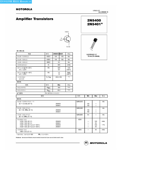
INCHES
DIM MIN MAX A 0.175 0.205 B 0.170 0.210 C 0.125 0.165 D 0.016 0.022 F 0.016 0.019 G 0.045 0.055 H 0.095 0.105 J 0.015 0.020 K 0.500 ––– L 0.250 ––– N 0.080 0.105 P ––– 0.100 R 0.115 ––– V 0.135 –––
小信号特性
电流 - 增益 - 带宽产品 (IC = 10 MADC,VCE = 10伏直流,F = 100兆赫)
输出电容
(VCB = 10 VDC,IE = 0,F = 1.0兆赫)
小信号电流增益
(IC = 1.0 MADC,VCE = 10伏直流,F = 1.0千赫)
噪声系数
(IC = 250 µAdc, VCE = 5.0伏,RS = 1.0千欧,F = 1.0千赫)
IC
600
PD
625
5.0
器件总功耗@ TC = 25°C 减免上述25℃
PD
1.5
12
工作和存储结 温度范围
TJ, Tstg - 55到+150
热特性
特性
符号
Max
热阻,结到环境 热阻,结到外壳
电气特性
RqJA
200
RqJC
83.3
(TA = 25°C除非另有说明)
特性
断特性
集电极 - 发射极击穿电压(1) (IC = 1.0 mAdc, IB = 0)
0.1
0 0.1 0.2 0.3 0.5 1.0 2.0 3.0 5.0
10 20 30 50 100
IC,集电极电流(mA)
2N5400G;2N5400RLRP;2N5400RLRPG;2N5400;中文规格书,Datasheet资料

2N5400Preferred DeviceAmplifier TransistorsPNP SiliconFeatures•Pb−Free Packages are Available*MAXIMUM RATINGSRating Symbol Value Unit Collector − Emitter Voltage V CEO120Vdc Collector − Base Voltage V CBO130Vdc Emitter − Base Voltage V EBO 5.0Vdc Collector Current − Continuous I C600mAdcT otal Device Dissipation @ T A = 25°C Derate above 25°C P D6255.0mWmW/°CT otal Device Dissipation @ T C = 25°C Derate above 25°C P D 1.512WmW/°COperating and Storage JunctionT emperature RangeT J, T stg−55 to +150°C THERMAL CHARACTERISTICSCharacteristic Symbol Max Unit Thermal Resistance, Junction−to−Ambient R q JA200°C/W Thermal Resistance, Junction−to−Case R q JC83.3°C/W Stresses exceeding Maximum Ratings may damage the device. Maximum Ratings are stress ratings only. Functional operation above the Recommended Operating Conditions is not implied. Extended exposure to stresses above the Recommended Operating Conditions may affect device reliability.*For additional information on our Pb−Free strategy and soldering details, pleasedownload the ON Semiconductor Soldering and Mounting T echniques Reference Manual, SOLDERRM/D.Preferred devices are recommended choices for future use and best overall value.See detailed ordering and shipping information in the package dimensions section on page 2 of this data sheet.ORDERING INFORMATIONELECTRICAL CHARACTERISTICS (T A = 25°C unless otherwise noted)Characteristic Symbol Min Max Unit OFF CHARACTERISTICSCollector−Emitter Breakdown Voltage (Note 1)(I C = 1.0 mAdc, I B = 0)V(BR)CEO120−VdcCollector−Base Breakdown Voltage(I C = 100 m Adc, I E = 0)V(BR)CBO130−VdcEmitter−Base Breakdown Voltage(I E = 10 m Adc, I C = 0)V(BR)EBO 5.0−VdcCollector Cutoff Current(V CB = 100 Vdc, I E = 0)(V CB = 100 Vdc, I E = 0, T A = 100°C)I CBO−−100100nAdcm AdcEmitter Cutoff Current(V EB = 3.0 Vdc, I C = 0)I EBO−50nAdc ON CHARACTERISTICS (Note 1)DC Current Gain(I C = 1.0 mAdc, V CE = 5.0 Vdc)(I C = 10 mAdc, V CE = 5.0 Vdc)(I C = 50 mAdc, V CE = 5.0 Vdc)h FE304040−180−−Collector−Emitter Saturation Voltage(I C = 10 mAdc, I B = 1.0 mAdc)(I C = 50 mAdc, I B = 5.0 mAdc)V CE(sat)−−0.20.5VdcBase−Emitter Saturation Voltage(I C = 10 mAdc, I B = 1.0 mAdc)(I C = 50 mAdc, I B = 5.0 mAdc)V BE(sat)−−1.01.0VdcSMALL−SIGNAL CHARACTERISTICSCurrent−Gain — Bandwidth Product(I C = 10 mAdc, V CE = 10 Vdc, f = 100 MHz)f T100400MHzOutput Capacitance(V CB = 10 Vdc, I E = 0, f = 1.0 MHz)C obo− 6.0pFSmall−Signal Current Gain(I C = 1.0 mAdc, V CE = 10 Vdc, f = 1.0 kHz)h fe30200−Noise Figure(I C = 250 m Adc, V CE = 5.0 Vdc, R S = 1.0 k W, f = 1.0 kHz)NF−8.0dB 1.Pulse T est: Pulse Width ≤ 300 m s, Duty Cycle ≤ 2.0%.ORDERING INFORMATIONDevice Package Shipping†2N5400TO−925000 Unit / Bulk2N5400G TO−92(Pb−Free)5000 Unit / Bulk2N5400RLRP TO−922000 T ape & Reel2N5400RLRPG TO−92(Pb−Free)2000 T ape & Reel†For information on tape and reel specifications, including part orientation and tape sizes, please refer to our Tape and Reel Packaging Specifications Brochure, BRD8011/D.Figure 1. DC Current GainI C , COLLECTOR CURRENT (mA)30100150h , C U R R E N T G A I NF E 7050Figure 2. Collector Saturation RegionI B , BASE CURRENT (mA)1.00.10.5 2.0100.21.05.020500.90.80.70.60.50.40.30.20.100.0050.010.020.05Figure 3. Collector Cut−Off RegionV BE , BASE−EMITTER VOLTAGE (VOLTS)V C E , C O L L E C T O R −E M I T T E R V O L T A G E (V OL T S ), C O L L E C T O R C U R R E N T ( A )μI C 1030.10.30.210210110010−110−210−300.10.20.30.40.50.60.7Figure 4. “On” Voltages I C , COLLECTOR CURRENT (mA)0.40.60.71.00.2Figure 5. Temperature CoefficientsI C , COLLECTOR CURRENT (mA)V , V O L T A G E (V O L T S )2.50.5102050100C , C A P A C I T A N C E (p F )100Figure 6. Switching Time Test Circuit V R , REVERSE VOLTAGE (VOLTS)0.90.80.50.30.10.330V , T E M P E R A T U R E C O E F F I C I E N T (m V /C )°θFigure 7. CapacitancesoutValues Shown are for I C @ 10 mA 0.51020501000.3302.01.51.00.50−0.5−1.0−1.5−2.0−2.51.02.03.05.07.010********t , T I M E (n s )100010020030050070010203050700.510200.33050100200I C , COLLECTOR CURRENT (mA)Figure 8. Turn−On Time t , T I M E (n s )20001002003005007002030700.20.51.02.0 5.010200.3 3.03050100200I C , COLLECTOR CURRENT (mA)Figure 9. Turn−Off Time1000PACKAGE DIMENSIONSTO−92 (TO−226)CASE 29−11ISSUE AMNOTES:1.DIMENSIONING AND TOLERANCING PER ANSI Y14.5M, 1982.2.CONTROLLING DIMENSION: INCH.3.CONTOUR OF PACKAGE BEYOND DIMENSION R IS UNCONTROLLED.4.LEAD DIMENSION IS UNCONTROLLED IN P AND BEYOND DIMENSION K MINIMUM.PLANEDIM MIN MAX MIN MAX MILLIMETERSINCHES A 0.1750.205 4.45 5.20B 0.1700.210 4.32 5.33C 0.1250.165 3.18 4.19D 0.0160.0210.4070.533G 0.0450.055 1.15 1.39H 0.0950.105 2.42 2.66J 0.0150.0200.390.50K 0.500−−−12.70−−−L 0.250−−− 6.35−−−N 0.0800.105 2.04 2.66P −−−0.100−−− 2.54R 0.115−−− 2.93−−−V0.135−−−3.43−−−NOTES:1.DIMENSIONING AND TOLERANCING PER ASME Y14.5M, 1994.2.CONTROLLING DIMENSION:MILLIMETERS.3.CONTOUR OF PACKAGE BEYOND DIMENSION R IS UNCONTROLLED.4.LEAD DIMENSION IS UNCONTROLLED IN P AND BEYOND DIMENSION K MINIMUM.DIM MIN MAX MILLIMETERS A 4.45 5.20B 4.32 5.33C 3.18 4.19D 0.400.54G 2.40 2.80J 0.390.50K 12.70−−−N 2.04 2.66P 1.50 4.00R 2.93−−−V3.43−−−STYLE 1:PIN 1.EMITTER2.BASE3.COLLECTORON Semiconductor and are registered trademarks of Semiconductor Components Industries, LLC (SCILLC). SCILLC reserves the right to make changes without further notice to any products herein. SCILLC makes no warranty, representation or guarantee regarding the suitability of its products for any particular purpose, nor does SCILLC assume any liability arising out of the application or use of any product or circuit, and specifically disclaims any and all liability, including without limitation special, consequential or incidental damages. “Typical” parameters which may be provided in SCILLC data sheets and/or specifications can and do vary in different applications and actual performance may vary over time. All operating parameters, including “Typicals” must be validated for each customer application by customer’s technical experts. SCILLC does not convey any license under its patent rights nor the rights of others. SCILLC products are not designed, intended, or authorized for use as components in systems intended for surgical implant into the body,or other applications intended to support or sustain life, or for any other application in which the failure of the SCILLC product could create a situation where personal injury or death may occur. Should Buyer purchase or use SCILLC products for any such unintended or unauthorized application, Buyer shall indemnify and hold SCILLC and its officers, employees,subsidiaries, affiliates, and distributors harmless against all claims, costs, damages, and expenses, and reasonable attorney fees arising out of, directly or indirectly, any claim of personal injury or death associated with such unintended or unauthorized use, even if such claim alleges that SCILLC was negligent regarding the design or manufacture of the part.SCILLC is an Equal Opportunity/Affirmative Action Employer. This literature is subject to all applicable copyright laws and is not for resale in any manner.PUBLICATION ORDERING INFORMATION分销商库存信息:ONSEMI2N5400G2N5400RLRP2N5400RLRPG 2N5400。
in4007中文资料_数据手册_参数
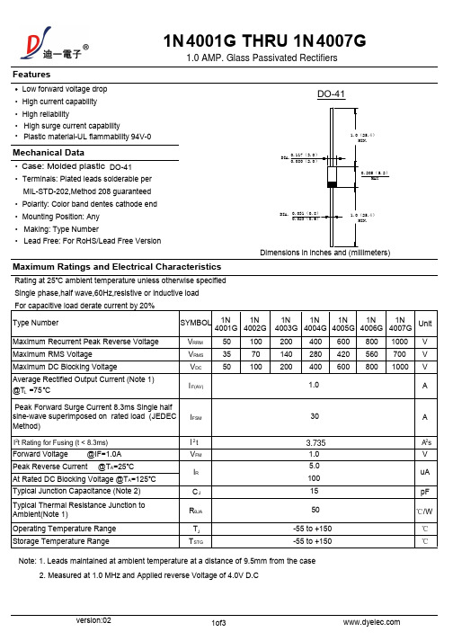
, PEAK FORWARD SURGE (A)
version:02
2of3
1N 4 ant Notice and Disclaimer
•Reproducing and modifying information of the document is prohibited without permission
•Since DIYI uses lot number as the tracking base, please provide the lot number for tracking when complaining.
version:02
3of3
万联芯城-电子元器件采购网,提供一站式配套,解决物料 烦恼,万联芯城销售电子元器件范围包括 IC 集成电路,电 阻电容,二三极管,可进行一站式 BOM 表配单,BOM 配 单整单采购可享优惠价,提交 BOM 表报价,最快可当天发 货,电子元器件一站式采购,满足客户多样化物料需求, 点击进入万联芯城。
SYMBOL 1N
1N
4001G 4002G
1N 4003G
1N 4004G
1N 4005G
1N 4006G
1N 4007G
Unit
VRRM
50
100 200 400 600 800 1000 V
VRMS
35
70
140 280 420 560 700 V
VDC
50 100 200 400 600 800 1000 V
•The products shown herein are not designed and authorized for equipments requiring high level of reliability or relating to human life and for any applications concerning life-saving or life-sustaining, such as medical instruments, transportation equipment, aerospace machinery et cetera. Customers using or selling these products for use in such applications do so at their own ris k andagree to fully indemnify DIYI for any damages resulting from such improper use or sale.
SNJ5400J中文资料

PACKAGING INFORMATIONOrderable Device Status(1)PackageType PackageDrawingPins PackageQtyEco Plan(2)Lead/Ball Finish MSL Peak Temp(3)JM38510/00104BCA ACTIVE CDIP J141None Call TI Level-NC-NC-NC JM38510/00104BDA ACTIVE CFP W141None Call TI Level-NC-NC-NC JM38510/07001BCA ACTIVE CDIP J141None Call TI Level-NC-NC-NC JM38510/07001BDA ACTIVE CFP W141None Call TI Level-NC-NC-NC JM38510/30001B2A ACTIVE LCCC FK201None Call TI Level-NC-NC-NC JM38510/30001BCA ACTIVE CDIP J141None Call TI Level-NC-NC-NC JM38510/30001BDA ACTIVE CFP W141None Call TI Level-NC-NC-NC JM38510/30001SCA ACTIVE CDIP J141None Call TI Level-NC-NC-NC JM38510/30001SDA ACTIVE CFP W141None Call TI Level-NC-NC-NC SN5400J ACTIVE CDIP J141None Call TI Level-NC-NC-NC SN54LS00J ACTIVE CDIP J141None Call TI Level-NC-NC-NC SN54S00J ACTIVE CDIP J141None Call TI Level-NC-NC-NCSN7400D ACTIVE SOIC D1450Pb-Free(RoHS)CU NIPDAU Level-2-260C-1YEAR/Level-1-235C-UNLIMSN7400DR ACTIVE SOIC D142500Pb-Free(RoHS)CU NIPDAU Level-2-260C-1YEAR/Level-1-235C-UNLIMSN7400N ACTIVE PDIP N1425Pb-Free(RoHS)CU NIPDAU Level-NC-NC-NC SN7400N3OBSOLETE PDIP N14None Call TI Call TISN7400NSR ACTIVE SO NS142000Pb-Free(RoHS)CU NIPDAU Level-2-260C-1YEAR/Level-1-235C-UNLIMSN74LS00D ACTIVE SOIC D1450Pb-Free(RoHS)CU NIPDAU Level-2-260C-1YEAR/Level-1-235C-UNLIMSN74LS00DBLE OBSOLETE SSOP DB14None Call TI Call TISN74LS00DBR ACTIVE SSOP DB142000Pb-Free(RoHS)CU NIPDAU Level-2-260C-1YEAR/Level-1-235C-UNLIMSN74LS00DR ACTIVE SOIC D142500Pb-Free(RoHS)CU NIPDAU Level-2-260C-1YEAR/Level-1-235C-UNLIMSN74LS00J OBSOLETE CDIP J14None Call TI Call TISN74LS00N ACTIVE PDIP N1425Pb-Free(RoHS)CU NIPDAU Level-NC-NC-NCSN74LS00NSR ACTIVE SO NS142000Pb-Free(RoHS)CU NIPDAU Level-2-260C-1YEAR/Level-1-235C-UNLIMSN74LS00PSR ACTIVE SO PS82000Pb-Free(RoHS)CU NIPDAU Level-2-260C-1YEAR/Level-1-235C-UNLIMSN74S00D ACTIVE SOIC D1450Pb-Free(RoHS)CU NIPDAU Level-2-260C-1YEAR/Level-1-235C-UNLIMSN74S00DR ACTIVE SOIC D142500Pb-Free(RoHS)CU NIPDAU Level-2-260C-1YEAR/Level-1-235C-UNLIMSN74S00N ACTIVE PDIP N1425Pb-Free(RoHS)CU NIPDAU Level-NC-NC-NC SN74S00N3OBSOLETE PDIP N14None Call TI Call TISN74S00NSR ACTIVE SO NS142000Pb-Free(RoHS)CU NIPDAU Level-2-260C-1YEAR/Level-1-235C-UNLIMSN74S00PSR ACTIVE SO PS82000Pb-Free(RoHS)CU NIPDAU Level-2-260C-1YEAR/Level-1-235C-UNLIMSNJ5400J ACTIVE CDIP J141None Call TI Level-NC-NC-NCOrderable Device Status(1)PackageType PackageDrawingPins PackageQtyEco Plan(2)Lead/Ball Finish MSL Peak Temp(3)SNJ5400W ACTIVE CFP W141None Call TI Level-NC-NC-NCSNJ5400WA OBSOLETE CFP WA14None Call TI Level-NC-NC-NC SNJ54LS00FK ACTIVE LCCC FK201None Call TI Level-NC-NC-NC SNJ54LS00J ACTIVE CDIP J141None Call TI Level-NC-NC-NC SNJ54LS00W ACTIVE CFP W141None Call TI Level-NC-NC-NC SNJ54S00FK ACTIVE LCCC FK201None Call TI Level-NC-NC-NCSNJ54S00J ACTIVE CDIP J141None Call TI Level-NC-NC-NCSNJ54S00W ACTIVE CFP W141None Call TI Level-NC-NC-NC(1)The marketing status values are defined as follows:ACTIVE:Product device recommended for new designs.LIFEBUY:TI has announced that the device will be discontinued,and a lifetime-buy period is in effect.NRND:Not recommended for new designs.Device is in production to support existing customers,but TI does not recommend using this part in a new design.PREVIEW:Device has been announced but is not in production.Samples may or may not be available.OBSOLETE:TI has discontinued the production of the device.(2)Eco Plan-May not be currently available-please check /productcontent for the latest availability information and additional product content details.None:Not yet available Lead(Pb-Free).Pb-Free(RoHS):TI's terms"Lead-Free"or"Pb-Free"mean semiconductor products that are compatible with the current RoHS requirements for all6substances,including the requirement that lead not exceed0.1%by weight in homogeneous materials.Where designed to be soldered at high temperatures,TI Pb-Free products are suitable for use in specified lead-free processes.Green(RoHS&no Sb/Br):TI defines"Green"to mean"Pb-Free"and in addition,uses package materials that do not contain halogens, including bromine(Br)or antimony(Sb)above0.1%of total product weight.(3)MSL,Peak Temp.--The Moisture Sensitivity Level rating according to the JEDECindustry standard classifications,and peak solder temperature.Important Information and Disclaimer:The information provided on this page represents TI's knowledge and belief as of the date that it is provided.TI bases its knowledge and belief on information provided by third parties,and makes no representation or warranty as to the accuracy of such information.Efforts are underway to better integrate information from third parties.TI has taken and continues to take reasonable steps to provide representative and accurate information but may not have conducted destructive testing or chemical analysis on incoming materials and chemicals.TI and TI suppliers consider certain information to be proprietary,and thus CAS numbers and other limited information may not be available for release.In no event shall TI's liability arising out of such information exceed the total purchase price of the TI part(s)at issue in this document sold by TI to Customer on an annual basis.元器件交易网元器件交易网IMPORTANT NOTICETexas Instruments Incorporated and its subsidiaries (TI) reserve the right to make corrections, modifications,enhancements, improvements, and other changes to its products and services at any time and to discontinueany product or service without notice. Customers should obtain the latest relevant information before placingorders and should verify that such information is current and complete. All products are sold subject to TI’s termsand conditions of sale supplied at the time of order acknowledgment.TI warrants performance of its hardware products to the specifications applicable at the time of sale inaccordance with TI’s standard warranty. T esting and other quality control techniques are used to the extent TIdeems necessary to support this warranty. Except where mandated by government requirements, testing of allparameters of each product is not necessarily performed.TI assumes no liability for applications assistance or customer product design. Customers are responsible fortheir products and applications using TI components. T o minimize the risks associated with customer productsand applications, customers should provide adequate design and operating safeguards.TI does not warrant or represent that any license, either express or implied, is granted under any TI patent right,copyright, mask work right, or other TI intellectual property right relating to any combination, machine, or processin which TI products or services are used. Information published by TI regarding third-party products or servicesdoes not constitute a license from TI to use such products or services or a warranty or endorsement thereof.Use of such information may require a license from a third party under the patents or other intellectual propertyof the third party, or a license from TI under the patents or other intellectual property of TI.Reproduction of information in TI data books or data sheets is permissible only if reproduction is withoutalteration and is accompanied by all associated warranties, conditions, limitations, and notices. Reproductionof this information with alteration is an unfair and deceptive business practice. TI is not responsible or liable forsuch altered documentation.Resale of TI products or services with statements different from or beyond the parameters stated by TI for thatproduct or service voids all express and any implied warranties for the associated TI product or service andis an unfair and deceptive business practice. TI is not responsible or liable for any such statements.Following are URLs where you can obtain information on other Texas Instruments products and applicationsolutions:Products ApplicationsAmplifiers Audio /audioData Converters Automotive /automotiveDSP Broadband /broadbandInterface Digital Control /digitalcontrolLogic Military /militaryPower Mgmt Optical Networking /opticalnetworkMicrocontrollers Security /securityTelephony /telephonyVideo & Imaging /videoWireless /wirelessMailing Address:Texas InstrumentsPost Office Box 655303 Dallas, Texas 75265Copyright 2005, Texas Instruments Incorporated。
Star针式打印机AR-5400+技术手册

Star针式打印机AR-5400+简体中文技术手册[第二版]引言本手册对于AR-5400+打印机作出了介绍,它是用作周期性检查和维謢的参考手册。
这是一本技术手册而不是普通用户的使用说明书。
●本手册分成如下章节:第一章一般规格第二章操作原理第三章调校第四章部份替换第五章维謢和润滑第六章故障检修第七章器件清单●第一版:2001年12月●第二版:2002年7月第一章一般规格1. 一般规格2. 外观及结构3. 控制面板3-1 开关组合功能3-2 EDS模式设定4. 并行接口4-1 一般规格4-2 接口信号5. 串行接口(可选件)5-1 一般规格5-2 接口信号5-3 DIP开关设置6. EE-PROM模式6-1 概述6-2 特殊控制码的说明6-3 EE-PROM图表6-4 重写EE-PROM1. 一般规格*** 表示半角。
耗电10W (等候状态)42W (草稿英数打印)寿命打印头2亿点/ 针色带LZ24HD:400万字符以上(草稿) 理想打印区域页首:1/6” (4.23mm)页尾:1/6” (4.23mm)彷真状态OKI5330SC (标准)ESC/P (可选)IBM PPDS (可选)操作环境温度:5℃~ 40℃湿度:10% ~ 80% (非结霜状态)MTBF:5000 P.O.H噪音:小于55 dB图1-1 整体尺寸2. 外观及结构图1-2 打印机前视图图1-3 打印机后视图图1-4 揭开面盖前视图图1-5 内部结构图3. 控制面版3-1. 开关组合功能图1-6 面板按钮组合功能3-2. EDS模式设置按住[頁首] 键开机则进入問答主式的EDS模式。
AR5400有三種彷真模式,它們的EDS功能如下:4. 并行接口4-1. 一般规格项目规格接口Centronics兼容同步方式通过外部提供的STROBE脉冲I/F协议通过ACK及BUSY信号逻辑电平与TTL电平相兼容图1-7 并行接口步进图4-2. 接口信号5. 串行接口(可选件)当使用串行接口时,串行-并行转换器应连接上打印机。
NCP1400ASN27T1G资料

NCP1400A100 mA, Fixed Frequency PWM Step−Up Micropower Switching RegulatorThe NCP1400A series are micropower step−up DC to DC converters that are specifically designed for powering portable equipment from one or two cell battery packs. These devices aredesigned to startup with a cell voltage of 0.8 V and operate down to less than 0.2 V. With only four external components, this series allows a simple means to implement highly efficient converters that are capable of up to 100 mA of output current.Each device consists of an on−chip fixed frequency oscillator, pulse width modulation controller, phase compensated error amplifier that ensures converter stability with discontinuous mode operation, soft−start, voltage reference, driver, and power MOSFET switch with current limit protection. Additionally, a chip enable feature is provided to power down the converter for extended battery life.The NCP1400A device series are available in the Thin SOT23−5 package with seven standard regulated output voltages. Additional voltages that range from 1.8 V to 4.9 V in 100 mV steps can be manufactured.Features•Extremely Low Startup V oltage of 0.8 V•Operation Down to Less than 0.2 V•Only Four External Components for Simple Highly Efficient Converters•Up to 100 mA Output Current Capability•Fixed Frequency Pulse Width Modulation Operation •Phase Compensated Error Amplifier for Stable Converter Operation •Chip Enable Power Down Capability for Extended Battery Life •Pb−Free Packages are AvailableTypical Applications•Cellular Telephones•Pagers•Personal Digital Assistants•Electronic Games•Digital Cameras•Camcorders•Handheld Instruments•White LED Torch LightTHIN SOT23−5SN SUFFIXCASE 483PIN CONNECTIONS ANDMARKING DIAGRAM13GNDCE2OUTNC4LX5(Top View)xxx= MarkingA= Assembly LocationY= YearW= Work WeekG= Pb−Free PackageSee detailed ordering and shipping information in the ordering information section on page 2 of this data sheet.ORDERING INFORMATIONVFigure 1. Typical Step−Up ConverterApplicationxxxAYWGG(Note: Microdot may be in either location)ORDERING INFORMATIONDevice OutputVoltageSwitchingFrequency Marking Package Shipping†NCP1400ASN19T1 1.9 V180 KHz DAI Thin SOT23−53000 / Tape & Reel(7 Inch Reel)NCP1400ASN19T1G 1.9 V DAI Thin SOT23−5 (Pb−Free)NCP1400ASN22T1 2.2 V DCN Thin SOT23−5NCP1400ASN22T1G 2.2 V DCN Thin SOT23−5 (Pb−Free)NCP1400ASN25T1 2.5 V DAV Thin SOT23−5NCP1400ASN25T1G 2.5 V DAV Thin SOT23−5 (Pb−Free)NCP1400ASN27T1 2.7 V DAA Thin SOT23−5NCP1400ASN27T1G 2.7 V DAA Thin SOT23−5 (Pb−Free)NCP1400ASN30T1 3.0 V DAB Thin SOT23−5NCP1400ASN30T1G 3.0 V DAB Thin SOT23−5 (Pb−Free)NCP1400ASN33T1 3.3 V DAJ Thin SOT23−5NCP1400ASN33T1G 3.3 V DAJ Thin SOT23−5 (Pb−Free)NCP1400ASN38T1 3.8 V DBK Thin SOT23−5NCP1400ASN38T1G 3.8 V DBK Thin SOT23−5 (Pb−Free)NCP1400ASN45T1 4.5 V DBL Thin SOT23−5NCP1400ASN45T1G 4.5 V DBL Thin SOT23−5 (Pb−Free)NCP1400ASN50T1 5.0 V DAD Thin SOT23−5NCP1400ASN50T1G 5.0 V DAD Thin SOT23−5 (Pb−Free)NOTE:The ordering information lists seven standard output voltage device options. Additional devices with output voltage ranging from1.8 V to 5.0 V in 100 mV increments can be manufactured. Contact your ON Semiconductor representative for availability.†For information on tape and reel specifications, including part orientation and tape sizes, please refer to our Tape and Reel Packaging Specifications Brochure, BRD8011/D.ABSOLUTE MAXIMUM RATINGSRating Symbol Value Unit Power Supply Voltage (Pin 2)V OUT−0.3 to 6.0V Input/Output PinsLX (Pin 5)LX Peak Sink Current V LXI LX−0.3 to 6.0400VmACE (Pin 1)Input Voltage Range Input Current Range V CEI CE−0.3 to 6.0−150 to 150VmAThermal Resistance Junction to Air R q JA250°C/W Operating Ambient Temperature Range (Note 2)T A−40 to +85°C Operating Junction Temperature Range T J−40 to +125°C Storage Temperature Range T stg−55 to +150°C Stresses exceeding Maximum Ratings may damage the device. Maximum Ratings are stress ratings only. Functional operation above the Recommended Operating Conditions is not implied. Extended exposure to stresses above the Recommended Operating Conditions may affect device reliability.1.This device series contains ESD protection and exceeds the following tests:Human Body Model (HBM) $2.0 kV per JEDEC standard: JESD22−A114.Machine Model (MM) $200 V per JEDEC standard: JESD22−A115.2.The maximum package power dissipation limit must not be exceeded.P D+T J(max)*T Aq JAtchup Current Maximum Rating: $150 mA per JEDEC standard: JESD78.4.Moisture Sensitivity Level (MSL): 1 per IPC/JEDEC standard: J−STD−020A.ELECTRICAL CHARACTERISTICS(For all values T A = 25°C, unless otherwise noted.)Characteristic Symbol Min Typ Max Unit OSCILLATORFrequency (V OUT = V SET x 0.96, Note 5)f OSC144180216kHz Frequency Temperature Coefficient (T A = −40°C to 85°C)D f−0.11−%/°C Maximum PWM Duty Cycle (V OUT = V SET x 0.96)D MAX687582% Minimum Startup Voltage (I O = 0 mA)V start−0.80.95V Minimum Startup Voltage Temperature Coefficient (T A = −40°C to 85°C)D V start−−1.6−mV/°C Minimum Operation Hold Voltage (I O = 0 mA)V hold0.3−−V Soft−Start Time (V OUT u 0.8 V)t SS0.5 2.0−ms LX (PIN 5)LX Pin On−State Sink Current (V LX = 0.4 V) Device Suffix:19T122T125T127T130T133T138T145T150T1I LX8080801001001001001001009090120125130135145155160−−−−−−−−−mAVoltage Limit (V OUT = V CE = V SET x 0.96, V LX “L’’ Side)V LXLIM0.650.8 1.0V Off−State Leakage Current (V LX = 5.0 V, T A = −40°C to 85°C)I LKG−0.5 1.0m A5.V SET means setting of output voltage.6.CE pin is integrated with an internal 150 nA pullup current source.ELECTRICAL CHARACTERISTICS (continued) (For all values T A = 25°C, unless otherwise noted.)Characteristic UnitMaxTypMinSymbolCE (PIN 1)CE Input Voltage (V OUT = V SET x 0.96)High State, Device Enabled Low State, Device Disabled V CE(high)V CE(low)0.9−−−−0.3VCE Input Current (Note 6)High State, Device Enabled (V OUT = V CE = 5.0 V) Low State, Device Disabled (V OUT = 5.0 V, V CE = 0 V)I CE(high)I CE(low)−0.5−0.50.150.50.5m ATOTAL DEVICEOutput Voltage (V IN = 0.7 x V OUT, I O = 10 mA) Device Suffix:19T122T125T127T130T133T138T145T150T1V OUT1.8532.1452.4382.6332.9253.2183.7054.38754.8751.92.22.52.73.03.33.84.55.01.9482.2552.5632.7683.0753.3833.8954.61255.125VOutput Voltage Temperature Coefficient (T A = −40°C to +85°C) Device Suffix:19T122T125T127T130T133T138T145T150T1D V OUT−−−−−−−−−100100100100100100150150150−−−−−−−−−ppm/°COperating Current 2 (V OUT = V CE = V SET +0.5 V, Note 5)I DD2−7.015m A Off−State Current (V OUT = 5.0 V, V CE = 0 V, T A = −40°C to +85°C, Note 6)I OFF−0.6 1.5m AOperating Current 1 (V OUT = V CE = V SET x 0.96, f OSC = 180 kHz) Device Suffix:19T122T125T127T130T133T138T145T150T1I DD1−−−−−−−−−2327323237374453705060606060606575100m A5.V SET means setting of output voltage.6.CE pin is integrated with an internal 150 nA pullup current source.2.01.9V O U T , O U T P U T V O L T A G E (V )1.8V O U T , O U T P U T V O L T A G E (V )Figure 6. NCP1400ASN30T1 Efficiency vs.Output Current I O , OUTPUT CURRENT (mA)Figure 7. NCP1400ASN50T1 Efficiency vs.Output CurrentI O , OUTPUT CURRENT (mA)E F F I C I E N C Y (%)1.71.61.00.80.60.40.2010080604020080706050I D D 1, O P E R A T I N G C U R R E N T (m A )403020100I D D 1, O P E R A T I N G C U R R E N T (m A )Figure 12. NCP1400ASN30T1 V LX Voltage Limitvs. Temperature T A , AMBIENT TEMPERATURE (°C)Figure 13. NCP1400ASN50T1 V LX Voltage Limitvs. TemperatureT A , AMBIENT TEMPERATURE (°C)V L X L I M , V L X , V O L T A G E L I M I T (V )D M A X , M A X I M U M D U T Y C Y C LE (%)V O U T , O U T P U T V O L T A G E (V )f O S C , O S C I L L A T O R F R E Q U E N C Y (k H z )Figure 18. NCP1400ASN30T1 Maximum DutyCycle vs. Temperature T A , AMBIENT TEMPERATURE (°C)Figure 19. NCP1400ASN50T1 Maximum DutyCycle vs. TemperatureT A , AMBIENT TEMPERATURE (°C)Figure 24. NCP1400ASNXXT1 LX Pin On−StateCurrent vs. Output Voltage V OUT , OUTPUT VOLTAGE (V)1401201008016018060I L X , L X P I N O N −S T A T E C U R R E N T (m A )V s t a r t , V h o l d , S T A R T U P A N D H O L D V O L T A G E (V )1.53.53.04.05.54.55.0Figure 25. NCP1400ASNXXT1 LX Switch On−Resistance vs. Output Voltage2.52.01.53.53.04.05.54.55.02.52.0V OUT , OUTPUT VOLTAGE (V)(V )I L X , L X P I N O N −S T A T E C U R R E N T (m A )806040201.60.601.61.41.21.0V s t a r t /V h o l d , S T A R T U P /H O L D V O L T A G E (V )0.80.60.40.20V s t a r t /V h o l d , S T A R T U P /H O L D V O L T A G E (V )Figure 30. NCP1400ASN30T1 Ripple Voltagevs. Output Current I O , OUTPUT CURRENT (mA)Figure 31. NCP1400ASN50T1 Ripple Voltagevs. Output CurrentI O , OUTPUT CURRENT (mA)1.41.01.20.80.40.2)V r i p p l e , R I P P L E V O L T A G E (m V )V OUT = 3.0 V, V IN = 1.2 V, I O = 10 mA., L = 22 m H, C OUT = 68 m F1.V LX,2.0 V/div2.V OUT, 20 mV/div, AC coupled3.I L, 100 mA/divFigure 32. Operating Waveforms (Medium Load)2 m s/divV OUT = 3.0 V, V IN = 1.2 V, I O = 25 mA., L = 22 m H, C OUT = 68 m F1.V LX,2.0 V/div2.V OUT, 20 mV/div, AC coupled3.I L, 100 mA/divFigure 33. Operating Waveforms (Heavy Load)2 m s/divV IN = 1.2 V, L = 22 m H1.V OUT =1.9 V (AC coupled), 50 mV/div2.I O=3.0 mA to 30 mAFigure 34. NCP1400ASN19T1Load Transient ResponseV IN = 1.2 V, L = 22 m H1.V OUT =1.9 V (AC coupled), 50 mV/div2.I O= 30 mA to3.0 mAFigure 35. NCP1400ASN19T1Load Transient ResponseV IN = 1.5 V, L = 22 m H1.V OUT =3.0 V (AC coupled), 50 mV/div2.I O=3.0 mA to 30 mAFigure 36. NCP1400ASN30T1Load Transient ResponseV IN = 1.5 V, L = 22 m H1.V OUT = 3.0 V (AC coupled), 50 mV/div2.I O= 30 mA to3.0 mAFigure 37. NCP1400ASN30T1Load Transient ResponseV IN = 1.5 V, L = 22 m H1.V OUT =5.0 V (AC coupled), 50 mV/div2.I O=3.0 mA to 30 mAFigure 38. NCP1400ASN50T1Load Transient ResponseV IN = 1.5 V, L = 22 m H1.V OUT = 5.0 V (AC coupled), 50 mV/div2.I O= 30 mA to3.0 mAFigure 39. NCP1400ASN50T1Load Transient ResponseLX5GND4NC3OUT2Figure 40. Representative Block DiagramPIN FUNCTION DESCRIPTIONPin #Symbol Pin Description1CE Chip Enable Pin(1) The chip is enabled if a voltage equal to or greater than 0.9 V is applied.(2) The chip is disabled if a voltage less than 0.3 V is applied.(3) The chip is enabled if this pin is left floating.2OUT Output voltage monitor pin and also the power supply pin for the device.3NC No internal connection to this pin.4GND Ground pin.5LX External inductor connection pin to power switch drain.DETAILED OPERATING DESCRIPTIONOperationThe NCP1400A series are monolithic power switching regulators optimized for applications where power drain must be minimized. These devices operate as fixed frequency, voltage mode boost regulator and is designed to operate in the discontinuous conduction mode. Potential applications include low powered consumer products and battery powered portable products.The NCP1400A series are low noise fixed frequency voltage−mode PWM DC−DC converters, and consist of soft−start circuit, feedback resistor, reference voltage, oscillator, loop compensation network, PWM control circuit, current limit circuit and power switch. Due to the on−chip feedback resistor and loop compensation network, the system designer can get the regulated output voltage from 1.8 V to 5.0 V with a small number of external components. The quiescent current is typically 32 m A (V OUT = 2.7 V), and can be further reduced to about 1.5 m A when the chip is disabled (V CE t 0.3 V).Soft−StartThere is a soft−start circuit in NCP1400A. When power is applied to the device, the soft−start circuit pumps up the output voltage to approximately 1.5 V at a fixed duty cycle, the level at which the converter can operate normally. What is more, the startup capability with heavy loads is also improved.OscillatorThe oscillator frequency is internally set to 180 kHz at an accuracy of "20% and with low temperature coefficient of 0.11%/°C. Figures 16 and 17 illustrate oscillator frequency versus temperature.Regulated Converter Voltage (V OUT)The V OUT is set by an internal feedback resistor network. This is trimmed to a selected voltage from 1.8 V to 5.0 V range in 100 mV steps with an accuracy of "2.5%. Note: When the duty cycle is less than about 12%, the regulator will skip switching cycles to maintain high efficiency at light loads. The regulated output will be raised by 3 to 4% under this pensationThe device is designed to operate in discontinuous conduction mode. An internal compensation circuit was designed to guarantee stability over the full input/output voltage and full output load range. Stability cannot be guaranteed in continuous conduction mode.Current LimitThe NCP1400A series utilizes cycle−by−cycle current limiting as a means of protecting the output switch MOSFET from overstress and preventing the small value inductor from saturation. Current limiting is implemented by monitoring the output MOSFET current build−up during conduction, and upon sensing an overcurrent conduction immediately turning off the switch for the duration of the oscillator cycle.The voltage across the output MOSFET is monitored and compared against a reference by the VLX limiter. When the threshold is reached, a signal is sent to the PWM controller block to terminate the output switch conduction. The current limit threshold is typically set at 350 mA.Enable/Disable OperationThe NCP1400A series offer IC shutdown mode by chip enable pin (CE pin) to reduce current consumption. An internal 150 nA pull−up current source tied the CE pin to OUT pin by default, i.e., user can float the pin CE for permanent “On’’. When voltage at pin CE is equal or greater than 0.9 V, the chip will be enabled, which means the regulator is in normal operation. When voltage at pin CE is less than 0.3 V, the chip is disabled, which means IC is shutdown.Important: DO NOT apply a voltage between 0.3 V to 0.9 V to pin CE as this voltage will place the IC into an undefined state and the IC may drain excessive current from the supply.APPLICATION CIRCUIT INFORMATIONFigure 41. Typical Step−Up Converter ApplicationV OUT V IN m FStep−up Converter Design Equations General step−up DC−DC converter designed to operate in discontinuous conduction mode can be defined by:D −Duty cycleI PK −Peak inductor current I O −Desired dc output currentV IN −Nominal operating dc input voltage V OUT −Desired dc output voltage V F −Diode forward voltageAssume saturation voltage of the internal FET switch is negligible.External Component SelectionInductorInductance values between 18 m H and 27 m H are the best suitable values for NCP1400A. In general, smaller inductance values can provide larger peak inductor current and output current capability, and lower conversion efficiency, and vice versa. Select an inductor with smallest possible DCR, usually less than 1.0 W , to minimize loss. It is necessary to choose an inductor with saturation current greater than the peak current which the inductor will encounter in the application. The inductor selected should be able to handle the worst case peak inductor current without saturation.DiodeThe diode is the largest source of loss in DC−DC converters. The most importance parameters which affect their efficiency are the forward voltage drop, V F , and the reverse recovery time, trr. The forward voltage drop creates a loss just by having a voltage across the device while a current flowing through it. The reverse recovery time generates a loss when the diode is reverse biased, and the current appears to actually flow backwards through the diode due to the minority carriers being swept from the P−N junction. A Schottky diode with the following characteristics is recommended:Small forward voltage, V F t 0.3 V Small reverse leakage currentFast reverse recovery time/switching speed Rated current larger than peak inductor current,I rated u I PKReverse voltage larger than output voltage,V reverse u V OUTInput CapacitorThe input capacitor can stabilize the input voltage and minimize peak current ripple from the source. The value of the capacitor depends on the impedance of the input source used. Small Equivalent Series Resistance (ESR) Tantalum or ceramic capacitor with value of 10 m F should be suitable.Output CapacitorThe output capacitor is used for sustaining the output voltage when the internal MOSFET is switched on and smoothing the ripple voltage. Low ESR capacitor should be used to reduce output ripple voltage. In general, a 47 m F to 68 m F low ESR (0.15 W to 0.30 W ) Tantalum capacitor should be appropriate.An evaluation board of NCP1400A has been made in the small size of 23 mm x 20 mm and is shown in Figures 42and 43. Please contact your ON Semiconductorrepresentative for availability. The evaluation boardschematic diagram, the artwork and the silkscreen of thesurface mount PCB are shown below:Figure 42. NCP1400A PWM Step−up DC−DC Converter Evaluation Board SilkscreenFigure 43. NCP1400A PWM Step−up DC−DC Converter Evaluation Board Artwork (Component Side)1Components SupplierPartsSupplierPart Number DescriptionPhone Inductor, L1Sumida Electric Co. Ltd.CR54−220MC Inductor 22 m H/1.11 A(852) 2880−6688Schottky Diode, D1ON Semiconductor Corp.MBR0520LT1Schottky Power Rectifier(852) 2689−0088Output Capacitor, C2KEMET Electronics Corp.T494D686K010AS Low ESR Tantalum Capacitor68 m F/10 V(852) 2305−1168Input Capacitor, C1KEMET Electronics Corp.T491C106K016ASLow Profile Tantalum Capacitor10 m F/16 V(852) 2305−1168PCB Layout HintsGroundingOne point grounding should be used for the output power return ground, the input power return ground, and the device switch ground to reduce noise as shown in Figure 44, e.g.:C2 GND, C1 GND, and U1 GND are connected at one point in the evaluation board. The input ground and output ground traces must be thick enough for current to flow through and for reducing ground bounce.Power Signal TracesLow resistance conducting paths should be used for the power carrying traces to reduce power loss so as to improveefficiency (short and thick traces for connecting the inductor L can also reduce stray inductance), e.g. short and thick traces listed below are used in the evaluation board:1.Trace from TP1 to L12.Trace from L1 to Lx pin of U13.Trace from L1 to anode pin of D14.Trace from cathode pin of D1 to TP2Output CapacitorThe output capacitor should be placed close to the output terminals to obtain better smoothing effect on the output ripple.D1MBR0520LT1Figure 44. NCP1400A Evaluation Board Schematic DiagramPACKAGE DIMENSIONSTHIN SOT23−5SN SUFFIX CASE 483−02ISSUE Cǒmm inchesǓSOLDERING FOOTPRINT**For additional information on our Pb−Free strategy and solderingdetails, please download the ON Semiconductor Soldering and Mounting Techniques Reference Manual, SOLDERRM/D.NOTES:1.DIMENSIONING AND TOLERANCING PER ANSI Y14.5M, 1982.2.CONTROLLING DIMENSION: MILLIMETER.3.MAXIMUM LEAD THICKNESS INCLUDES LEAD FINISH THICKNESS. MINIMUM LEAD THICKNESS IS THE MINIMUM THICKNESS OF BASE MATERIAL.4. A AND B DIMENSIONS DO NOT INCLUDE MOLD FLASH, PROTRUSIONS, OR GATE BURRS.DIM MIN MAX MIN MAX INCHES MILLIMETERS A 2.90 3.100.11420.1220B 1.30 1.700.05120.0669C 0.90 1.100.03540.0433D 0.250.500.00980.0197G 0.85 1.050.03350.0413H 0.0130.1000.00050.0040J 0.100.260.00400.0102K 0.200.600.00790.0236L 1.25 1.550.04930.0610M 0 10 0 10 S 2.50 3.000.09850.1181____ON Semiconductor and are registered trademarks of Semiconductor Components Industries, LLC (SCILLC). SCILLC reserves the right to make changes without further notice to any products herein. SCILLC makes no warranty, representation or guarantee regarding the suitability of its products for any particular purpose, nor does SCILLC assume any liability arising out of the application or use of any product or circuit, and specifically disclaims any and all liability, including without limitation special, consequential or incidental damages.“Typical” parameters which may be provided in SCILLC data sheets and/or specifications can and do vary in different applications and actual performance may vary over time. All operating parameters, including “Typicals” must be validated for each customer application by customer’s technical experts. SCILLC does not convey any license under its patent rights nor the rights of others. SCILLC products are not designed, intended, or authorized for use as components in systems intended for surgical implant into the body, or other applications intended to support or sustain life, or for any other application in which the failure of the SCILLC product could create a situation where personal injury or death may occur. Should Buyer purchase or use SCILLC products for any such unintended or unauthorized application, Buyer shall indemnify and hold SCILLC and its officers, employees, subsidiaries, affiliates,and distributors harmless against all claims, costs, damages, and expenses, and reasonable attorney fees arising out of, directly or indirectly, any claim of personal injury or death associated with such unintended or unauthorized use, even if such claim alleges that SCILLC was negligent regarding the design or manufacture of the part. SCILLC is an Equal Opportunity/Affirmative Action Employer. This literature is subject to all applicable copyright laws and is not for resale in any manner.PUBLICATION ORDERING INFORMATION。
EPM240GT100C4N中文资料(Altera)中文数据手册「EasyDatasheet - 矽搜」
由MAX II系列支持.
表1-5 显示外部电源电压
表 1-5. MAX II外接电源电压
设备
多电压内核外部电源电压(V 多电压I / O接口电压电平(V 须知 表 1-5: (1)MAX IIG和MAX IIZ器件只接受1.8 V他们 (2)MAX II器件在1.8 V内部操作
) (2) )
EPM 240 EPM 570 EPM 1270 EPM 2210
3.3 V / 2.5 V或1.8 V ■ 多电压I / O接口,支持3.3 V,2.5 V,1.8 V和1.5 V逻辑电平 ■ 总线型架构,包括可编程摆率,驱动能力,
总线防护持,和可编程上拉电阻
■ 施密特触发器能够容忍噪声输入(每个引脚可编程)
■ I / O是完全符合外围组件互连特别 兴趣小组(PCI SIG)PCI本地总线规范,修订2.2 3.3 V 工作在66兆赫
100-Pin FineLine
BGA
100-Pin TQFP
0.5
0.5
1
0.5
25
36
121
256
5×5
6×6
11 × 11 16 × 16
144-Pin TQFP
0.5 484 22 × 22
144-Pin Micro FineLine BGA
256-Pin Micro FineLine BGA
256-Pin FineLine
BGA
324-Pin FineLine
BGA
0.5
0.5
1
1
49
121
289
361
7×7
11 × 11 17 × 17 19 × 19
芯片中文手册,看全文,戳
EPM9320LC84-15N中文资料(Altera)中文数据手册「EasyDatasheet - 矽搜」
84-Pin 208-Pin 240-Pin 280-Pin 304-Pin 356-Pin
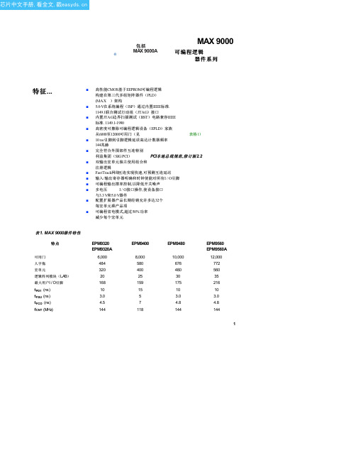
PLCC RQFP RQFP PGA RQFP BGA
EPM9320 60 (2)
132
–
168
–
168
EPM9320A 60 (2)
132
–
–
–
168
EPM9400 59 (2)
139
159
–
–
–
EPM9480
Note: (1) 内部逻辑阵列模块显示(LAB)性能.括号内数字显示,从行外部延迟
输入端子排I / O引脚.
速度等级
-15 118 118 118 7.9 (15) 10.9 (18)
-20
100 100 100 10 (20) 16 (26)
在MAX 9000架构支持系统级逻辑功能高密度集成.它很容易集成多个 可编程逻辑器件,从好朋友,GAL和22V10s到现场可编程门阵列(FPGA) 器件和EPLD中.
图1
示出MAX 9000体系结构框图.
5
–
146
175
–
–
–
EPM9560
–
153
191
216
216
216
EPM9560A
–
153
191
–
–
216
注意事项: (1) MAX 9000器件封装类型包括塑料J引线芯片载体(PLCC),功率四方扁平封装(
RQFP),陶瓷针栅阵列(PGA),和球栅阵列(BGA)封装.
(2) 犯设计这种设备之前执行完整热分析
Units
MHz MHz MHz ns ns
3
SINAMICS G150 样本(中文)
C lo s e d -Io o p -c o n tr o l
D ia g n o s is
H e lp
ESC
OK
首先,选择所使用的电机类型 (技术数据符合标准 IEC 或 NEMA)。
Select Motortype ( IEC/ NEMA)
1 2 3
4
5
操作面板 1 通电指示灯 (绿色) 2 报警指示灯 (黄色) 3 故障指示灯 (红色) 4 数字键盘 5 键盘锁 6 显示 7 功能键 F1 - F5 8 本地 / 远程优先级的选择 9 驱动控制小键盘
1
变频调速柜
SINAMICS G150
■ 特性 (续)
• 结构紧凑,模块化设计,极易维护 • 无故障设计 • 易于连接,装配简单 • 调试快速,菜单提示,无需复杂参数化 • 舒适型图形化操作面板,操作简便,一目了然,测量值以纯
文本或准模拟条形图显示
质量
SINAMICS G150 变频调速柜是按最高质量标准和要求监造。 产品具有最大的可靠性、可用性和功能性。
A&D Mall 网址: /automation/mall
DA 12 DA 21.1 DA 22 DA 63 DA 65.10 M 11 SD 01 CA 01
SINAMICS G150 变频调速柜 订货样本 D 11
2004 年 6 月
本样本所及产品和系统 均为最高质量监造,获得 德国 DQS 认证,符合标 准 DIN EN ISO 9001。 DQS 认证为所有 EQ Net 获得国际认可。
110 kW - 560 kW (~800kW)
SINAMICS G150 变频调速柜,结构紧凑,模块化设计,维修 方便。
丰富的电气和机械选件,可使驱动系统优化用于各种应用。
SGL40N150D中文资料
Electrical Characteristics of DIODE T C= 25°C unless otherwise notedI GESG-E Leakage CurrentV GE = V GES , V CE = 0V----± 100nAOn CharacteristicsV GE(th)G-E Threshold Voltage I C = 40mA, V CE = V GE 3.5 5.07.5V V CE(sat)Collector to Emitter Saturation VoltageI C = 40A , V GE = 15V-- 3.74.7VDynamic CharacteristicsC ies Input Capacitance V CE = 10V , V GE = 0V, f = 1MHz--4000--pF C oes Output Capacitance--700--pF C resReverse Transfer Capacitance--300--pFSwitching Characteristicst d(on)Turn-On Delay Time V CC = 600V, I C = 40A,R G = 51Ω, V GE = 15V,Resistive Load, T C = 25°C --90200ns t r Rise Time--230700ns t d(off)Turn-Off Delay Time --245400ns t f Fall Time--230400ns Q g Total Gate Charge V CE = 600V, I C = 40A,V GE = 15V--140170nC Q ge Gate-Emitter Charge --2525nC Q gcGate-Collector Charge--4560nCSymbol ParameterTest ConditionsMin.Typ.Max.Units V FM Diode Forward Voltage I F = 10A-- 1.3 1.8V t rrDiode Reverse Recovery TimeI F = 10A, di/dt = 200A/us--170300nsTRADEMARKSThe following are registered and unregistered trademarks Fairchild Semiconductor owns or is authorized to use and is not intended to be an exhaustive list of all such trademarks.DISCLAIMERFAIRCHILD SEMICONDUCTOR RESERVES THE RIGHT TO MAKE CHANGES WITHOUT FURTHER NOTICE TO ANY PRODUCTS HEREIN TO IMPROVE RELIABILITY, FUNCTION OR DESIGN. FAIRCHILD DOES NOT ASSUME ANY LIABILITY ARISING OUT OF THE APPLICATION OR USE OF ANY PRODUCT OR CIRCUIT DESCRIBED HEREIN;NEITHER DOES IT CONVEY ANY LICENSE UNDER ITS PATENT RIGHTS, NOR THE RIGHTS OF OTHERS.LIFE SUPPORT POLICYFAIRCHILD’S PRODUCTS ARE NOT AUTHORIZED FOR USE AS CRITICAL COMPONENTS IN LIFE SUPPORT DEVICES OR SYSTEMS WITHOUT THE EXPRESS WRITTEN APPROVAL OF FAIRCHILD SEMICONDUCTOR CORPORATION.As used herein:1. Life support devices or systems are devices or systems which, (a) are intended for surgical implant into the body,or (b) support or sustain life, or (c) whose failure to perform when properly used in accordance with instructions for use provided in the labeling, can be reasonably expected to result in significant injury to the user.2. A critical component is any component of a life support device or system whose failure to perform can be reasonably expected to cause the failure of the life support device or system, or to affect its safety or effectiveness.PRODUCT STATUS DEFINITIONS Definition of TermsDatasheet Identification Product Status DefinitionAdvance InformationFormative or In Design This datasheet contains the design specifications for product development. Specifications may change in any manner without notice.PreliminaryFirst ProductionThis datasheet contains preliminary data, andsupplementary data will be published at a later date.Fairchild Semiconductor reserves the right to make changes at any time without notice in order to improve design.No Identification Needed Full ProductionThis datasheet contains final specifications. Fairchild Semiconductor reserves the right to make changes at any time without notice in order to improve design.Obsolete Not In ProductionThis datasheet contains specifications on a product that has been discontinued by Fairchild semiconductor.The datasheet is printed for reference information only.STAR*POWER is used under licenseACEx™Bottomless™CoolFET™CROSSVOLT ™DenseTrench™DOME™EcoSPARK™E 2CMOS™EnSigna™FACT™FACT Quiet Series™FAST ®FASTr™FRFET™GlobalOptoisolator™GTO™HiSeC™I 2C™ISOPLANAR™LittleFET™MicroFET™MicroPak™MICROWIRE™OPTOLOGIC™OPTOPLANAR™PACMAN™POP™Power247™PowerTrench ®QFET™QS™QT Optoelectronics™Quiet Series™SLIENT SWITCHER ®SMART START™SPM™STAR*POWER™Stealth™SuperSOT™-3SuperSOT™-6SuperSOT™-8SyncFET™TinyLogic™TruTranslation™UHC™UltraFET ®VCX™。
液晶常用电源管理芯片
1200AP40 1200AP60、1203P60 200D6、203D6 DAP8A 可互代203D6/1203P6 DAP8A 2S0680 2S0880 3S0680 3S0880 5S0765 DP104、DP704 8S0765C DP704加24V的稳压二极管ACT4060 ZA3020LV/MP1410/MP9141 ACT4065 ZA3020/MP1580 ACT4070 ZA3030/MP1583/MP1591MP1593/MP1430 ACT6311 LT1937 ACT6906 LTC3406/AT1366/MP2104 AMC2576 LM2576 AMC2596 LM2596 AMC3100 LTC3406/AT1366/MP2104 AMC34063A AMC34063 AMC7660 AJC1564 AP8012 VIPer12A AP8022 VIPer22A DAP02 可用SG5841 /SG6841代换DAP02ALSZ SG6841 DAP02ALSZ SG6841 DAP7A、DP8A 203D6、1203P6 DH321、DL321 Q100、DM0265R DM0465R DM/CM0565R DM0465R/DM0565R 用cm0565r代换〔取掉4脚的稳压二极管〕DP104 5S0765 DP704 5S0765 DP706 5S0765 DP804 DP904 FAN7601 LAF0001 LD7552 可用SG6841代〔改4脚电阻〕LD7575PS 203D6改1脚100K电阻为24K OB2268CP OB2269CP OB2268CP SG6841改4脚100K电阻为20-47K OCP1451 TL1451/BA9741/SP9741/AP200 OCP2150 LTC3406/AT1366/MP2104 OCP2160 LTC3407 OCP2576 LM2576 OCP3601 MB3800 OCP5001 TL5001 OMC2596 LM2596/AP1501 PT1301 RJ9266 PT4101 AJC1648/MP3202 PT4102 LT1937/AJC1896/AP1522/RJ9271/MP1540 SG5841SZ SG6841DZ/SG6841D SM9621 RJ9621/AJC1642 SP1937 LT1937/AJC1896/AP1522/RJ9271/MP1540 STR-G5643D STR-G5653D、STR-G8653D TEA1507 TEA1533 TEA1530 TEA1532对应引脚功能接入THX202H TFC719 THX203H TFC718S TOP246Y TOP247Y VA7910 MAX1674/75 L6920 AJC1610 VIPer12AVIPer22A [audio01]ICE2A165(1A/650V.31W);ICE2A265(2A/650V.52W);ICE2B0565(0.5A/6 50V.23W):ICE2B165(1A/650V.31W);ICE2B265(2A/650V.52W);ICE2A180(1A/800V.29W);ICE2 A280(2A/800.50W).KA5H0365R, KA5M0365R, KA5L0365R, KA5M0365RN# u) t! u1 W1 B) R, PKA5L0365RN, KA5H0380R, KA5M0380R, KA5L0380R1、KA5Q1265RF/RT〔大小两种体积〕、KA5Q0765、FSCQ1265RT、KACQ1265RF、FSCQ0765RT、FSCQ1565Q这是一类的,这些型号的引脚功能全都一样,只是输出功率不一样。
- 1、下载文档前请自行甄别文档内容的完整性,平台不提供额外的编辑、内容补充、找答案等附加服务。
- 2、"仅部分预览"的文档,不可在线预览部分如存在完整性等问题,可反馈申请退款(可完整预览的文档不适用该条件!)。
- 3、如文档侵犯您的权益,请联系客服反馈,我们会尽快为您处理(人工客服工作时间:9:00-18:30)。
1N5400GP THRU 1N5408GP
3 Amp Glass Passivated Rectifier 50 - 1000 Volts
DO-201AD
Low Current Leakage Metalurgically Bonded Construction Low Forward Voltage High Current Capability Glass Passivated Junction
D
1N5400GP 1N5401GP 1N5402GP 1N5404GP 1N5406GP 1N5407GP 1N5408GP
---------------
35V 70V 140V 280V 420V 560V 700V
A Cathode Mark B
D
Electrical Characteristics @ 25°C Unless Otherwise Specified
MCC
Figure 5 Peak Forward Surge Current
2
8 10 Cycles
20
40
60 80 100
Peak Forward Surge Current - Amperesversus Number Of Cycles At 60Hz - Cycles
1N5400GP thru 1N5408GP
Figure 1 Typical Forward Characteristics 20 10 6 4 2.5 2 Amps 1 .6 .4 .2 25°C .1 .06 .04 .02 .01 .4 .6 .8 Volts Instantaneous Forward Current - Amperesversus Instantaneous Forward Voltage - Volts 1.0 1.2 1.4 0 .5 Amps 1.0 2 3.0
MCC
Figure 2 Forward Derating Curve
1.5
Single Phase, Half Wave 60Hz Resistive or Inductive Load 0 50 75 100 °C Average Forward Rectified Current - Amperes versus Ambient Temperature - °C 125 150 175
C
DIMENSIONS INCHES MIN ----.048 1.000 MM MIN ----1.20 25.40
DIM A B C D
MAX .370 .250 .052 ---
MAX 9.50 6.40 1.30 ---
NOTE
元器件交易网
Average Forward IF(AV) 3.0A TA = 105°C Current Peak Forward Surge IFSM 200A 8.3ms, half sine Current Maximum 1.1V IFM = 3.0A; Instantaneous VF Forward Voltage TJ = 25°C* Maximum DC Reverse Current At IR 5.0µA TJ = 25°C Rated DC Blocking 50µA TJ = 125°C Voltage Typical Junction CJ 40pF Measured at Capacitance 1.0MHz, VR=4.0V *Pulse test: Pulse width 300 µsec, Duty cycle 1%
Figure 3 Junction Capacitance
100 60 40 20 pF 10 6 4 2 1 .1 .2 .4 1 Volts 2 4 10 20 40 100 200 400 1000 TJ=25°C
Junction Capacitance - pFversus Reverse Voltage - Volts
元器件交易网
1N5400GP thru 1N5408GP
Figure 4 Typical Reverse Characteristics 100 60 40 20 10 6 4 2 µAmps 1 .6 .4 .2 .1 .06 .04 .02 .01 20 40 60 80 Volts Instantaneous Reverse Leakage Current - MicroAmperes versus Percent Of Rated Peak Reverse Voltage - Volts 100 120 140 TA=25°C Amps 300 250 200 150 100 50 0 1 4 6
• • •
Maximum Ratings
Operating Temperature: -55°C to +150°C Storage Temperature: -55°C to +150°C Maximum Thermal Resistance; 30 °C/W Junction To Lead MCC Catalog Number Device Marking Maximum Recurrent Peak Reverse Voltage 50V 100V 200V 400V 600V 800V 1000V Maximum RMS Voltage Maximum DC Blocking Voltage 50V 100V 200V 400V 600V 800V 1000V
元器件交易网
MCC
Features
• • • • •
omponents 21201 Itasca St% !"#
