AM335x:ARM Cortex—A8微处理器开发方案
TI AM3358 ARM Cortex-A8微处理器测试评估和开发解决方案

TI AM3358 ARM Cortex-A8微处理器测试评估和开发解决方案关键字:工业控制,家庭和工业自动化,售货机,智能收费系统;消费类电子,游戏机外设,玩具TI 公司的TMDXEVM3358是AM335x ARM Cortex-A8微处理器的评估模块,能对AM335x 处理器(AM3352, AM3354, AM3356, AM3358) 进行测试评估和开发,包括EVM基板,子板和LCD显示模块,主要用于游戏机外设,售货机,家庭和工业自动化,称重仪,消费类医疗设备,教育控制台,打印机,高挡玩具和智能收费系统.本文介绍了AM335x 主要特性,方框图,AM335x评估模块(EVM)系统框图,基板和子板方框图,电路图以及PCB布局图.TIThe AM335x microprocessors, based on the ARM Cortex-A8, are enhanced with image, graphics processing, peripherals and industrial interface options such as EtherCAT and PROFIBUS. The device supports the followinghigh-level operating systems (HLOSs) that are available free of charge from TI: • Linux®• Windows® CE• Android™The AM335x microrocessor contains these subsystems:• Microprocessor unit (MPU) subsystem based on the ARM Cortex-A8 microprocessor.• POWERVR SGX™ Graphics Accelerator subsystem for 3D graphics acceleration to support display and gaming effects.• Programmable Real-Time Unit Subsystem (PRUSS) enables the user to create a variety of digital resources beyond native peripherals of the device. In addition, the PRUSS is separate from the ARM core. This allows independent operation and clocking to give the device greater flexibility in complex system solutions.AM335x 主要特性:AM335x 应用:• Gaming Peripherals• Connected Vending Machines • Home and Industrial Automation • Weighing Scales• Consumer Medical Appliances • Educational Consoles• Printers• Advanced Toys• Smart Toll Systems图1.AM335x 功能方框图AM335x评估模块(EVM)The AM335x Evaluation Module (EVM) enables developers to immediately start evaluating AM335x processors (AM3352, AM3354, AM3356, AM3358) and begin building applications such as portable navigation, portable gaming and home/building automation, among others.The AM335x general purpose EVM is a standalone test, development, and evaluation module system that enables developers to write software and develop hardware around an AM335x processor subsystem.The main elements of the AM335x subsystem are already available on the base board of the EVM, which gives developers the basic resources needed for most general purpose type projects that encompass the AM335x as themain processor. Additional typical type peripherals are built into the EVM such as memory, sensors, LCD, Ethernet PHY, etc. so that prospective systems can be modeled quickly without significant additional hardware resources.The System View of the AM335x General Purpose EVM consists the baseboard, daughterboard, and LCD display board stacked together and connected through standard throughhole connectors. See the pictures below of the EVM.图2.AM335x评估模块(EVM)外形图图3.AM335x评估模块(EVM)系统框图图4.AM335x 15x15 基板方框图图5.AM335x通用子板方框图图6.AM335x 15x15 基板电路图(1)图7.AM335x 15x15 基板电路图(2)图8.AM335x 15x15 基板电路图(3)图9.AM335x 15x15 基板电路图(4)图10.AM335x 15x15 基板电路图(5)图11.AM335x 15x15 基板电路图(6)图12.AM335x 15x15 基板电路图(7)图13.AM335x 15x15 基板电路图(8)图14.AM335x 15x15 基板电路图(9)图15.AM335x 15x15 基板电路图(10)图16.AM335x 15x15 基板电路图(11)图17.AM335x 15x15 基板电路图(12)图18.AM335x 15x15 基板电路图(13)图19.AM335x 15x15 基板电路图(14)图20.AM335x EVM通用子板电路图(1)图21.AM335x EVM通用子板电路图(2)图22.AM335x EVM通用子板电路图(3)图23.AM335x EVM通用子板电路图(4)图24.AM335x EVM通用子板电路图(5)图25.AM335x EVM通用子板电路图(6)图26.AM335x EVM通用子板电路图(7)图27.AM335x EVM通用子板电路图(8)图28.AM335x EVM通用子板电路图(9)图29.AM335x EVM通用子板电路图(10)图30.AM335x EVM通用子板电路图(11)图31.AM335x EVM通用子板电路图(12)图32.AM335x EVM通用子板电路图(13)图33.AM335x EVM基板PCB元件布局图:顶层图34.AM335x EVM基板PCB元件布局图:底层图35.AM335x EVM通用子板PCB元件布局图:顶层图36.AM335x EVM通用子板PCB元件布局图:底层。
03 AM335x处理器
• EMIF0 SDRAM
– 0x8000_0000 0xBFFF_FFFF, 1GB 8-/16-bit External Memory, (ex/e/w)
北京交通大学
国家电工电子教学基地
Main processor
ARM Cortex-A8 MPU子系统
• MPU 子系统处理 ARM A8核心 , L3 互联和中断控制 器 (INTC)之间的 数据交换. • MPU把A8处理器 和其他附加逻辑 集成在一起,实 现协议转换、仿 真、中断处理和 调试增强功能。
L3 Slow clock domain
目标模块 : 只能响应 r/w请求
To L4 interconnect
北京交通大学国家电工电子教学基地 Main processor
L4 互联结构*
北京交通大学
国家电工电子教学基地
Main processor
片上模块 (驱动开发相关)
• cache : 高速缓存 • mDDR: 移动双倍速率同步动态随机存储器 • PRU-ICSS: 可编程实时单元和工业用通信子系统
• AXI2OCP桥
– 支持OCP 2.2.
– 在两个端口实现单次请求多个数据协议。 – 多个目标,包括三个 OCP ports (128-bit, 64-bit and 32-bit).
• 中断控制器
– 最多支持128个中断请求
• 仿真/调试
– 与CoreSight结构兼容
• 时钟产生
– 通过PRCM(电源、复位、时钟微控制器)
北京交通大学
国家电工电子教学基地
Main processor
存储器子系统: GPMC
• GPMC 为器件提供访问NAND Flash, NOR Flash和其他异步/同步接 口外设 的手段.
TI-am335x_处理器全面介绍(AM3358-AM3359-AM3354-AM3352)

• Home/Building/Industrial automation
• Consumer Electronics • Control Solutions • Educational consoles
4
AM335x Cortex™-A8 based processors
Benefits
• • High performance Cortex-A8 at ARM9/11 prices Rich peripheral integration reduces system complexity and cost
Full function and low cost development platforms fit your evaluation and cost requirements
3
AM335x microprocessors are ideal for:
• Portable Navigation • Advanced toys • Connected vending machines Network Connectivity Graphical User Interface Interface Options Affordable Tools Design Flexibility
EMAC 2port 10/100/1G w/1588 & switch (MII,RMII, RGMII)
Power Estimates
Schedule and packaging
• Samples: Today; Production: 2Q’12 • Dev. Tools: Today • Docs: Today • Packaging: 13x13, 0.65mm via channel array 15x15, 0.8mm
飞凌AM335x开发板Linux用户手册

飞凌AM335x开发板Linux用户手册OK335X-Linux用户手册第一章OK335X简介OK335X开发板基于TI AM335X处理器,运行主频最高720M,支持Linux,WinCE,Android三大操作系统,可用于工业产品设计。
OK335X有核心板和底板组成,核心板主要芯片有:CPU,NandFlash,Memory,PowerManage。
使用我们的核心板,只需要根据您的业务需求开发自己的底板,这样可加速您的产品上市时间,让您从平台搭建的复杂环境中脱离。
下面我们具体描述OK335X核心板和底板资源。
OK335X产品图片如下所示:核心板硬件资源:1CPU主频:720M(支持AM3352,AM3354,AM3356,AM3357,AM3358,AM3359)2NandFlash:256M(Micro SLC)3Memory:265M(Micro DDR2)4PowerManage IC:TPS65217B(TI AM335X专用电源IC)底板资源:14路串口(2个232电平,2个TTL电平,232电平已经使用DB9座子引出,其中COM0作为调试串口使用,注意:OK335X-V1底板中UART4暂时不能使用,下一硬件版本将修正这个问题)。
21路100M网口3音频接口(1路Phone输出,1路Line-in输入)41个SD卡接口56个用户按键63路I2C接口71个LCD接口(支持RGB888模式,支持电阻触摸和电容触摸。
默认标配7寸电阻屏)81路PWM接口,用于蜂鸣器测试。
91路Can接口101路SDIO接口11多路用户IO接口12四路USB2.0接口,一路USB2.0OTG(目前板子为一路USB Host接口,后续会增加到四路USB HUB)131路SPI接口148路AD(其中4路用于电阻触摸,1路用于滑动变阻器AD测试,其余3路通过插针引出,另外滑动变阻器端有跳线设置,通过跳线可以设置这路AD用于插针引出,还是用于可调电阻测试)15引出总线接口(缺省未焊接底座)161个RESET按钮,用于系统复位。
珠海鼎芯 AM335x EVM硬件用户手册
A8_RGMII1_MDIO_CLK
7
A8_RGMII1_MDIO_DATA
8
A8_RGMII1_RXCLK
9~12
A8_RGMII1_RXD[0..3]
13~16
A8_RGMII1_TXD[0..3]
17
A8_RGMII1_TXCLK
18
A8_RGMII1_TXEN
19
A8_RGMII1_RXDV
系列
Up to 720MHz ARM Cortex™-A8 32bit RISC内核
NEON™SIMD协处理器
Power VR SGX™5303D图形加速处理引擎
RAM
256MByte DDR3
PMIC
TPS 65910
电源
5V DC
晶振
24MHz主时钟
32.768KHz RTC时钟
LED
2个运行指示灯
3.2.1处理器
AM335x作为开发板的核心处理器,提供高达720MHz的主频速度。AM335x支持mDDR/DDR2/DDR3,并配有NEON™SIMD协处理器、SGX5303D图形引擎。同时AM335x提供了丰富的接口资源。极高的性价比,使得它能适用性极广。开发板围绕AM335x设计的资源,为开发者提供了基于AM335x系列的硬件和软件开发的所有可能性。
TPS65910
AM335x
Voltage
VAUX2
VDDSHV6
3.3V
VMMC
VDDSHV2,3,4,5,VDDA3P3V_USB0/1
3.3V
VDD2 SMPS
VDD_CORE
1.1V
VDD1 SMPS
VDD_MPU
1.2V
飞凌嵌入式AM335x产品规格书-2014-09-18

第 3页
OK335x 产品规格书 2014-09-18
第一章 产品说明
1.1 产品总述
OK335x 系列产品是由飞凌自主设计、生产和发行销售的高性能,工业级开发平台。开 发平台采用了 TI 公司的 AM335X Cortex-A8 处理器,运行主频高达 1GHz,AM335X 处理器集 成了两个千兆网卡,集成了 CAN 总线控制器,IIC 控制器,LCD 控制器,集成了 PowerVR SGX530 图形处理器,非常适合工业控制,多媒体终端等应用领域。
第四章 OK335xS-II 产品................................................................................................................20 4.1 产品概述............................................................................................................................20 4.1.1 FET335xS-II 概述................................................................................................... 20 4.1.2 OK335xS-II 概述.....................................................................................................21 4.2 产品参数............................................................................................................................22 4.2.1 FET335xS-II 硬件参数........................................................................................... 22 4.2.2 FET335xS-II 软件参数........................................................................................... 22 4.2.3 OK335xS-II 接口说明............................................................................................24 4.3 OK335xS-II 尺寸说明....................................................................................................25 4.3.1 FET335xS-II 核心板尺寸说明图........................................................................... 25 4.3.2 OK335xS-II 底板尺寸说明图.................................................................................25
AM335x的linux内核移植

摘要随着时代的发展,人们的生活越来越离不开电子产品,特别是嵌入式电子产品。
嵌入式的发展越来越好,得益于硬件的发展和各类嵌入式系统的进步。
在众多的嵌入式系统中,最为让人熟悉的就是linux了。
所以,这次的课题就以linux 内核为主题,使用的开发板是TI的beaglebone white。
关键词:Linux移植,嵌入式,arm目录1.嵌入式系统的概念 (4)1.1嵌入式系统定义 (4)1.2ATMEL9200开发平台 (4)2.BootLoader简介 (4)2.1 Boot Loader概念 (4)2.2 Boot Loader启动过程 (5)2.3 常用的Bootloader…………………………………………… .52.4 u-boot移植…………………………………………………… .53.嵌入式linux操作系统 (7)3.1 嵌入式Linux (7)3.2 嵌入式Linux的特点 (7)3.3 从Linux到嵌入式Linux (8)4. 基于BeagleBone的嵌入式linux系统移植 (9)4.1 移植概念 (9)4.2 Linux与移植相关内核结构 (9)4.3 嵌入式Linux 操作系统移植 (9)5 文件系统构建 (9)6 把u-boot、linux内核、文件系统下载到SD卡中 (11)7启动开发板,链接pc,查看效果 (11)8 参考文献 (13)1.嵌入式系统的概念1.1嵌入式系统定义在信息科学技术爆炸式增长的今天,嵌入式系统早已经融入了我们生活的方方面面。
美国汽车大王福特公司的高级经理曾宣称,“福特出售的‘计算能力’已超过了IBM”。
这并不是一个哗众取宠或者夸张的说法,在真正感受这句话的震撼力之前,让我们先了解一下嵌入式系统(Embedded Systems)的定义:以应用为中心、以计算机技术为基础、软件硬件可裁剪、适应应用系统对功能、可靠性、成本、体积、功耗严格要求的专用计算机系统。
基于AM335X平台的Ethercat实现
Application Report Lit. Number – Month Year12基于AM335X平台的Ethercat实现1 EtherCAT 简介EtherCAT(以太网控制自动化技技)是一种用于确定性以太网的高性能技业通信协议,它扩展了IEEE 802.3以太网标准,使得数据传输中具有可预测性定时及高精度同步等特点。
这个开放性标准作为IEC 61158的组成部分,常用于机械设计及运动控制等应用中。
EtherCAT 采用标准的IEEE802-3以太网帧,帧结构如图1。
EtherCAT 协议直接用标准以太网的帧格嵌传输数据,并不修改其基本结构。
图1 EtherCAT 数据帧数据帧EtherCAT 实现了CANOpen 协议,在CANOpen 中周期性的数据通过PDO(过技数据对象)来传输,PDO 优先级比较高用于实时传输。
非周期性的数据比如配置参数等则通过SDO(服务数据对象)来传输。
每个PDO 都包含单个或多个从设备的地址,这种数据加地址的结构(附带用于校验的传输计数位)组成了EtherCAT 的报文。
每个Ethernet 帧可能包含数个报文,而一个周期中可能需摘多帧来传送所需的所有报文。
传统的以太网通信解决方案从站先接受以太网数据包,然后解释和复制过技数据,最后转发数据。
而EtherCAT 以太网帧在特殊的硬件模块的帮助下可以实现在传输的同时被处处。
在每个从节点都有FMMU(现场总线存储管处单元),FMMU 会对经过的数据包进行地址分析,发现是本节点的数据就会读取,同时报文转发给下一个设备。
同样在报文通过的时候也可以插嵌数据。
读取/插嵌/转发数据的整个过技报文只有几纳秒的延迟。
如图2所示,设想以太网的帧就像行驶中的火车,EtherCAT 报文是每节火车车厢,PDO 数据的比特就是车厢内的乘客,这些数据可以被提取并插嵌到合适的从设备中。
整辆火车不停止地穿越所有从设备,在末端从设备处又掉头,重新反向穿越所有从设备。
AM335x核心板
2
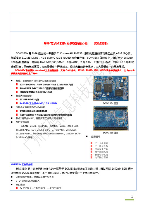
基于 TI AM335x 处理器的核心板——SOM335x
SOM335x 是 EMA 推出的一款基于 TI Cortex-A8 AM335x 系列处理器的低功耗工业级 ARM 核心板, 板载高达 512MB DDR3,4GB eMMC /1GB NAND 大容量存储。SOM335x 体积极小,通过两个 2x50pin B2B 插针连接器,将多路 UART/IIC/SPI/MMC、8 路 ADC、2 路 CAN、2 路千兆 MAC、24bit LCD 等外设 全部引出,系统集成度高,有效降低客户开发成本。提供完善的参考设计,大大降低客户的开发周期。
1
1xRS485(DB9接口) 1x 3.3V TTL UART(TJC3接口) n n n n n n n n n n n 1x DCAN 2.0B(DB9接口) 1x 千兆网口 1x WIFI Module(可选) 8x 12-bit ADC/TSC 1x 24bit LCD接口 2x USB 2.0 Host 2x SPI总线接口 1x 蜂鸣器 1x6-bit 启动拨码开关 1x14针JTAG标准接口 音频接口 1x双声道扬声器输出接口 1x双声道麦克风输入接口 n 按钮 1x复位按键 1x自定义按键 n n MMC/SD/SDIO/SDHC卡槽,最高支持32GByte 扩展功能接口 1x GPMC总线接口 2x USB 2.0 Host接口 2x USB 2.0 OTG接口 1x Reset信号线 1x MDIO总线 Linux 操作系统 Bootloader:u-boot 2011.9, 支持从 SD Card/eMMC/NAND 启动,支持串口和网络下载 内核版本:Linux3.2,文件系统:UBIFS 相关驱动:eMMC,CAN, Serial port, RTC, Ethernet, LCD, McSPI, EEPROM, Touch screen, MMC/SD , USB OTG, USB , Audio input/output 等 Android 操作系统 Android 版本:Android4.0 内核版本:Linux3.2 I-Android 工业控制套件: 支持 CAN 总线、RS232、RS485、I2C、GPIO 设备等设备接入
AM335x Sitara

ProductFolderSample &BuyTechnical Documents Tools &SoftwareSupport &Community Reference DesignAM3359,AM3358,AM3357,AM3356,AM3354,AM3352ZHCS488H –OCTOBER 2011–REVISED MAY 2015AM335x Sitara™处理器1器件概述中的PRU-ICSS 、AVS 、和DVFS 列表项1.1特性•8KB 带有单位检错(奇偶校验)的指令RAM •高达1GHz Sitara™ARM ®Cortex ®-A832位精简指令集计算机(RISC)处理器•8KB 带有单位检错(奇偶校验)的数据RAM –NEON™单指令流多数据流(SIMD)协处理器•具有64位累加器的单周期32位乘法器–32KB L1指令和32KB 带有单位检错(奇偶校•增强型GPIO 模块为外部信号提供移入/移出验)的数据缓存支持以及并行锁断–带有错误校正码(ECC)的256KB L2缓存–12KB 带有单位检错(奇偶校验)的共享RAM –176KB 片载启动ROM –三个120字节寄存器组,可被每个PRU 访问–64KB 专用RAM –用于处理系统输入事件的中断控制器模块(INTC)–仿真和调试-JTAG–用于将内部和外部主机连接到PRU-ICSS 内部资源的本地互连总线–中断控制器(最多可控制128个中断请求)–PRU-ICSS 内的外设:•片上存储器(共享L3RAM )•一个带有流控制引脚的通用异步收发器–64KB 通用片上存储器控制器(OCMC)随机存取(UART)端口,支持高达12Mbps 的数据速率存储器(RAM)•一个增强型捕捉(eCAP)模块–可访问所有主机•两个MII 以太网端口,支持工业以太网(例如–支持保持以实现快速唤醒EtherCAT )•外部存储器接口(EMIF)•一个MDIO 端口–mDDR(LPDDR)、DDR2、DDR3、DDR3L 控制•电源、复位和时钟管理(PRCM)模块器:–控制待机模式和深度休眠模式的进入和退出•mDDR :200MHz 时钟(400MHz 数据速率)–负责休眠排序、电源域关闭排序、唤醒排序和电•DDR2:266MHz 时钟(532MHz 数据速率)源域打开排序•DDR3:400MHz 时钟(800MHz 数据速率)–时钟•DDR3L :400MHz 时钟(800MHz 数据速•集成了15MHz 至35MHz 的高频振荡器,用率)于为各种系统和外设时钟生成参考时钟•16位数据总线•支持子系统和外设的单独时钟使能和禁用控•1GB 全部可寻址空间制,帮助降低功耗•支持一个x16或两个x8存储器件配置•五个用于生成系统时钟(MPU 子系统、DDR –通用存储器控制器(GPMC)接口、USB 、外设[MMC 和SD 、UART 、•灵活的8位和16位异步存储器接口,具有多SPI 、I 2C]、L3、L4、以太网、GFX达七个片选(NAND 、NOR 、复用NOR 和[SGX530]以及LCD 像素时钟)的ADPLL SRAM )–电源•使用BCH 代码,支持4位、8位或16位•两个不可切换的电源域(实时时钟[RTC]和ECC唤醒逻辑[WAKEUP])•使用海明码来支持1位ECC •3个可切换电源域(MPU 子系统–错误定位器模块(ELM)[MPU],SGX530[GFX],外设和基础设施•与GPMC 一起使用时,可通过BCH 算法确[PER])定所生成的伴随多项式中数据错误的地址•执行SmartReflex™2B 类,基于芯片温度、•根据BCH 算法,支持4位、8位和16位每过程变化和性能实现内核电压调节(自适应电512字节块错误定位压调节[AVS])•可编程实时单元子系统和工业通信子系统(PRU-•动态电压频率缩放(DVFS)ICSS)•实时时钟(RTC)–支持EtherCAT ®、PROFIBUS 、PROFINET 、–实时日期(年、月、日和星期几)和时间(小EtherNet/IP™等协议时、分钟和秒)信息–2个可编程实时单元(PRU)–内部32.768kHz 振荡器,RTC 逻辑和1.1V 内部•32位可运行在200MHz 的负载/存储RISC 处理低压降稳压器(LDO)器–独立的加电复位(RTC_PWRONRSTn)输入AM3359,AM3358,AM3357,AM3356,AM3354,AM3352ZHCS488H–OCTOBER2011–REVISED –用于外部唤醒事件的专用输入引脚(EXT_•DMTIMER1是用于操作系统(OS)节拍的WAKEUP)1ms定时器–可编程警报可用于生成PRCM内部中断(用于唤•DMTIMER4–DMTIMER7为引脚输出醒)或Cortex-A8内部中断(用于事件通知)–一个安全装置定时器–可编程警报可与外部输出(PMIC_POWER_EN)–SGX5303D图形引擎一起用来使能电源管理IC,从而恢复非RTC电•拼图架构每秒可提供最多2000万个多边形源域•通用可扩展着色引擎(USSE)是一款包含像素•外设和顶点着色功能的多线程引擎–多达两个带有集成PHY的USB2.0高速OTG•超过Microsoft VS3.0、PS3.0和OGL2.0的端口高级着色功能集–多达两个工业千兆位以太网MAC(10、100和•Direct3D Mobile、OGL-ES1.1和2.0、1000Mbps)OpenVG1.0以及OpenMax的行业标准API •集成开关支持•每个MAC都支持MII、RMII、RGMII和•精细的任务切换、负载均衡和电源管理MDIO接口•高级几何DMA驱动型操作,最大程度地减少•以太网MAC和交换机可独立于其它功能运行CPU交互•IEEE1588v2精密时间协议(PTP)•可编程高质量图像防锯齿–多达2个控制器局域网(CAN)端口•用于统一存储器架构中操作系统运行的完全虚•支持CAN版本2部分A和B拟化存储器寻址–多达两个多通道音频串行端口(McASP)–LCD控制器•高达50MHz的发送和接收时钟•多达24位数据输出;每像素8位(RGB)•每个具有独立TX和RX时钟的McASP端口•分辨率最高可达2048×2048(具有最高对应多达四个串行数据引脚126MHz的像素时钟)•支持时分多路复用(TDM)、内部IC声音•集成LCD接口显示驱动器(LIDD)控制器(I2S)和类似格式•集成光栅控制器•支持数字音频接口传输(SPDIF、IEC60958-•集成DMA引擎可通过中断或固件定时器从外1和AES-3格式)部帧缓冲器获取数据,无需加重处理器的负担•用于发送和接收的FIFO缓冲器(256字节)•512字深内部FIFO–最多6个UART•支持的显示类型:•所有UART支持IrDA和CIR模式–字符显示器-使用LIDD控制器对这些显•所有UART支持RTS和CTS流量控制示器进行编程•UART1支持完整的调制解调器控制–无源矩阵LCD显示-使用LCD光栅显示控制器来为到无源显示的持续图形刷新提供–多达两个主从McSPI串行接口定时和数据•最多2个芯片选择–有源矩阵LCD显示-使用外部帧缓冲器空•高达48MHz间和内部DMA引擎来驱动到控制面板的–多达三个MMC、SD和SDIO端口流数据•1位、4位和8位MMC、SD和SDIO模式–12位逐次逼近寄存器(SAR)ADC •MMCSD0具有专用于1.8V或3.3V操作的电•每秒采集200K个样本源轨•可从8:1模拟开关复用的八个模拟输入中任意•高达48MHz的数据传输速率选择输入•支持卡检测和写保护•可配置为用作4线、5线或8线电阻式触摸•符合MMC4.3、SD和SDIO2.0规范屏控制器(TSC)接口–多达三个I2C主从接口–多达三个32位eCAP模块•标准模式(高达100kHz)•可配置为三个捕捉输入或者三个备用PWM输•快速模式(高达400kHz)出–多达四组通用I/O(GPIO)引脚–多达三个增强型高分辨率PWM模块(eHRPWM)•每组包含32个GPIO引脚(与其他功能引脚•具有时间和频率控制功能的16位专用时基计复用)数器•GPIO引脚可作为中断输入(每组多达两个中•可配置为6个单端,6个双边对称,或者3断输入)个双边不对称输出–多达三个外部直接存储器访问(DMA)事件输入也–多达3个32位增强型正交编码脉冲(eQEP)模可用作中断输入块–八个32位通用定时器•器件标识AM3359,AM3358,AM3357,AM3356,AM3354,AM3352 ZHCS488H–OCTOBER2011–REVISED MAY2015–包含电子熔丝组(FuseFarm),其中一些位厂家可•处理器间通信(IPC)编程–集成了基于硬件的IPC邮箱,以及用于Cortex-A8、PRCM和PRU-ICSS之间进程同步的•生产IDSpinlock•器件部件号(唯一的JTAG ID)•生成中断的邮箱寄存器•设备版本(可由主机ARM读取)–4个初启程序(Cortex-•调试接口支持A8,PRCM,PRU0,PRU1)–用于ARM(Cortex-A8和PRCM)和PRU-•自旋锁具有128个软件指定的锁寄存器ICSS调试的JTAG和cJTAG•安全性–支持器件边界扫描–密码硬件加速器(AES,SHA,PKA,RNG)–支持IEEE1500•启动模式•DMA–通过锁存在PWRONRSTn输入引脚上升沿上的–片上增强型DMA控制器(EDMA)搭载三个第三启动配置引脚来选择启动模式方传送控制器(TPTC)和一个第三方通道控制器(TPCC),支持多达64个可编程逻辑通道和8个•封装:QDMA通道。
MYD-AM335X 快速使用手册
图 1-1
1.3 产品特性
以下简单列出 MYD-AM335X 开发板的一些基本特性。 第3页
MYD-AM335X 快速使用手册
电气参数: 工作温度: 工业级:-40℃ ~+85℃ 商业级:0℃ ~+ 70℃ 工作相对湿度:20%~90%,非冷凝 电气指标: 底板:+5V/2A 电源供电 核心板:3.3V/0.8A 电源供电 PCB 板层: 底板,4 层,喷锡工艺生产,独立的接地信号层,无铅 核心板,6 层,沉金工艺生产,独立的接地信号层,无铅 机械尺寸: 底板:【130*100】mm,厚 1.6mm 核心板:【70*50】mm,厚 1.6mm
音频接口: 一个音频 3.5mm 输入接口 一个双声道音频 3.5mm 输出接口
液晶触摸屏接口: 16 位真彩色 默认 480 x 272 分辨率(4.3 寸屏),支持 7 寸屏(800 x 480),芯片支持最大分辨 率 1366 x 768
2.2.1 CPU......................................................................................................................... 8 2.2.2 DDR3 SDRAM....................................................................................................... 9 2.2.3 NANDFLASH 模块................................................................................................ 9 2.2.4 ETHERNET 模块................................................................................................. 10 2.3 底板介绍 ..................................................................................................................... 10 2.3.1 系统供电模块与按键模块 .................................................................................. 12 2.3.2 CAN 收发器.......................................................................................................... 13 2.3.3 RS485 收发器...................................................................................................... 14 2.3.4 排针接口 ............................................................................................................... 15 2.3.5 音频模块 ............................................................................................................... 16 2.3.6 USB 模块.............................................................................................................. 17 2.3.7 SP3232 串口........................................................................................................ 19 2.4 跳线设置 ..................................................................................................................... 19 2.5 硬件勘误 ..................................................................................................................... 20 第 3 章 软件资源介绍 ........................................................................................................21 3.1 Linux 软件资源............................................................................................................ 21 3.2 Android 软件资源........................................................................................................ 22 3.3 Windows Embedded Compact 7 ............................................................................. 22 第 4 章 启动开发板 ............................................................................................................24
德州仪器 Sitara AM335x ARM Cortex-A8硬件说明

Sitara™AM335x ARM®Cortex™-A8 Microprocessors(MPUs)Silicon Revisions2.1,2.0,1.0 Silicon ErrataLiterature Number:SPRZ360FOctober2011–Revised November2013Contents 1Introduction (3)1.1AM335x Device and Development Support Tool Nomenclature (3)1.2Revision Identification (4)2All Errata Listed With Silicon Revision Number (6)3Usage Notes and Known Design Exceptions to Functional Specifications (8)3.1Usage Notes (8)3.1.1LCD:Color Assignments of LCD_DATA Terminals (8)3.1.2DDR3:JEDEC Compliance for Maximum Self-Refresh Command Limit (8)3.1.3Boot:USB Boot ROM Code Uses Default DATAPOLARITY (9)3.1.4Boot:Multiplexed Signals GPMC_WAIT0,GMII2_CRS,and RMII2_CRS_DV Cause NAND BootIssue (9)3.1.5Pin Multiplexing:Valid IO Sets and Restrictions (10)3.1.6Boot:Multiplexed Signals GPMC_WAIT0and GMII2_CRS Cause NAND Boot Issue (10)3.1.7OSC1:RTC_XTALIN Terminal Has an Internal Pull-up Resistor When OSC1is Disabled (11)3.2Known Design Exceptions to Functional Specifications (12)Revision History (38)2Table of Contents SPRZ360F–October2011–Revised November2013Submit Documentation FeedbackCopyright©2011–2013,Texas Instruments IncorporatedSilicon ErrataSPRZ360F–October2011–Revised November2013Sitara™AM335x ARM®Cortex™-A8Microprocessors(MPUs)(Silicon Revision2.1,2.0,1.0)1IntroductionThis document describes the known exceptions to the functional specifications for the Sitara™AM335x ARM®Cortex™-A8Microprocessors(MPUs).[See the Sitara AM335x ARM Cortex-A8Microprocessors (MPUs)data manual(literature number SPRS717).]For additional information,see the latest version of the Sitara AM335x ARM Cortex-A8Microprocessors (MPUs)Technical Reference Manual(literature number SPRUH73).1.1AM335x Device and Development Support Tool NomenclatureTo designate the stages in the product development cycle,TI assigns prefixes to the part numbers of all microprocessors(MPUs)and support tools.Each device has one of three prefixes:X,P,or null(no prefix) (for example,XAM3358ZCE).Texas Instruments recommends two of three possible prefix designators for its support tools:TMDX and TMDS.These prefixes represent evolutionary stages of product development from engineering prototypes(TMDX)through fully qualified production devices and tools(TMDS).Device development evolutionary flow:X—Experimental device that is not necessarily representative of the final device's electrical specifications and may not use production assembly flow.P—Prototype device that is not necessarily the final silicon die and may not necessarily meet final electrical specifications.null—Production version of the silicon die that is fully qualified.Support tool development evolutionary flow:TMDX—Development-support product that has not yet completed Texas Instruments internal qualification testing.TMDS—Fully-qualified development-support product.X and P devices and TMDX development-support tools are shipped against the following disclaimer:"Developmental product is intended for internal evaluation purposes."Production devices and TMDS development-support tools have been characterized fully,and the quality and reliability of the device have been demonstrated fully.TI's standard warranty applies.Predictions show that prototype devices(X or P)have a greater failure rate than the standard production devices.Texas Instruments recommends that these devices not be used in any production systembecause their expected end-use failure rate still is undefined.Only qualified production devices are to be used.Sitara is a trademark of Texas Instruments.Cortex is a trademark of ARM Ltd or its subsidiaries.ARM is a registered trademark of ARM Ltd or its subsidiaries.All other trademarks are the property of their respective owners.3 SPRZ360F–October2011–Revised November2013Sitara™AM335x ARM®Cortex™-A8Microprocessors(MPUs)(SiliconRevision2.1,2.0,1.0) Submit Documentation FeedbackCopyright©2011–2013,Texas Instruments IncorporatedLot Trace CodeDevice RevisionLot Trace Code Device RevisionIntroduction 1.2Revision IdentificationThe device revision can be determined by the symbols marked on the top of the package.Figure 1provides an example of the AM335x device markings.Figure 1.Example of Device Revision Codes for the AM335x MicroprocessorNOTES:(A)Non-qualified devices are marked with the letters "X"or "P"at the beginning of the device name,while qualified devices have a "blank"at the beginning of the device name.(B)The AM3352and AM3359devices shown in this device marking example are two of several valid part numbers for the AM335x family of devices.(C)The device revision code is the device revision (A,B,and so on).(D)YM denotes year and month.(E)LLLL denotes Lot Trace Code.(F)962is a generic family marking ID.(G)G1denotes green,lead-free.(H)ZCE or ZCZ is the package designator.(I)S denotes Assembly Site Code.(J)On some "X"devices,the device speed may not be shown.4SPRZ360F–October 2011–Revised November 2013Sitara™AM335x ARM ®Cortex™-A8Microprocessors (MPUs)(Silicon Revision 2.1,2.0,1.0)Submit Documentation FeedbackCopyright ©2011–2013,Texas Instruments Incorporated Introduction Silicon revision is identified by a code marked on the package.The code is of the format AM3352x orAM3358x,where"x"denotes the silicon revision.Table1lists the information associated with each silicon revision for each device type.For more details on device nomenclature,see the device-specific datamanual.Table1.Production Device Revision CodesDEVICE REVISION CODE SILICON REVISION COMMENTS(blank) 1.0Silicon revision is newA 2.0Silicon revision2.0B 2.1Silicon revision2.1Each silicon revision uses a specific revision of TI's ARM®Cortex™-A8processor.The ARM Cortex-A8 processor variant and revision can be read from the Main ID Register.The DEVREV field(bits31-28)of the Device_ID register located at address0x44E10600provides a4-bit binary value that represents the device revision.The ROM code revision can be read from address2BFFCh.The ROM code versionconsists of two decimal numbers:major and minor.The major number is always22,minor number counts ROM code version.The ROM code version is coded as hexadecimal readable values;for example,ROM version22.02is coded as00002202h.Table2shows the ARM Cortex-A8Variant and Revision,Device Revision,and ROM Code Revision values for each silicon revision of the device.Table2.Silicon Revision VariablesSILICON ARM CORTEX-A8DEVICE ROMREVISION VARIANT AND REVISION REVISION REVISION1.0r3p2000022.022.0r3p2000122.032.1r3p2001022.035 SPRZ360F–October2011–Revised November2013Sitara™AM335x ARM®Cortex™-A8Microprocessors(MPUs)(SiliconRevision2.1,2.0,1.0) Submit Documentation FeedbackCopyright©2011–2013,Texas Instruments IncorporatedAll Errata Listed With Silicon Revision Number 2All Errata Listed With Silicon Revision NumberAdvisories are numbered in the order in which they were added to this document.Some advisory numbers may be moved to the next revision and others may have been removed because the design exception was fixed or documented in the device-specific data manual or peripheral user's guide.When items are moved or deleted,the remaining numbers remain the same and are not re-sequenced.Table3.All Usage NotesSILICON REVISION AFFECTED NUMBER TITLE1.02.0 2.1Section3.1.1LCD:Color Assignments of LCD_DATA Terminals X X XDDR3:JEDEC Compliance for Maximum Self-RefreshSection3.1.2X X XCommand LimitSection3.1.3Boot:USB Boot ROM Code Uses Default DATAPOLARITY X X XBoot:Multiplexed Signals GPMC_WAIT0,GMII2_CRS,andSection3.1.4XRMII2_CRS_DV Cause NAND Boot IssueSection3.1.5Pin Multiplexing:Valid IO Sets and Restrictions X X XBoot:Multiplexed Signals GPMC_WAIT0and GMII2_CRSSection3.1.6X XCause NAND Boot IssueOSC1:RTC_XTALIN Terminal Has an Internal Pull-upSection3.1.7X X XResistor When OSC1is DisabledTable4.All Design Exceptions to Functional SpecificationsSILICON REVISION AFFECTED NUMBER TITLE1.02.0 2.1DDR2,DDR3,mDDR PHY:Control and Status RegistersAdvisory1.0.1X X XConfigured for Write OnlyDebug Subsystem:EMU[4:2]Signals Are Not Available byAdvisory1.0.2X X XDefault After ResetDebug Subsystem:Internal Inputs Tied-off to the WrongAdvisory1.0.3X X XValueAdvisory1.0.4PRU-ICSS:Clock Domain Crossing(CDC)Issue XAdvisory1.0.5RTC:32.768-kHZ Clock is Gating Off XEXTINTn:Input Function of the EXTINTn Terminal isAdvisory1.0.6XInvertedAdvisory1.0.7Boot:Ethernet Boot ROM Code PHY Link Speed Detection XBoot:Ethernet Boot ROM Code Sends an Incorrect VendorAdvisory1.0.8XClass Identifier in BOOTP PacketEthernet Media Access Controller and Switch Subsystem:Advisory1.0.9C0_TX_PEND and C0_RX_PEND Interrupts Not Connected Xto ARM Cortex-A8GMII_SEL Register:RGMII1_IDMODE andAdvisory1.0.10RGMII2_IDMODE Bits Reset to Non-supported Mode of XOperationUSB:Attached Non-compliant USB Device that RespondsAdvisory1.0.11Xto Spurious Invalid Short Packet May Lock Up BusUART:Extra Assertion of FIFO Transmit DMA Request,Advisory1.0.12X X XUARTi_DMA_TXUSB:Data May be Lost When USB Subsystem is OperatingAdvisory1.0.13in DMA Mode and More Than One Endpoint is Transferring XDataGMII_SEL and CPSW Related Pad Control Registers:Advisory1.0.14Context of These Registers is Lost During Transitions of XPD_PERARM Cortex-A8:OPP50Operation on MPU Domain NotAdvisory1.0.15XSupported6SPRZ360F–October2011–Revised November2013 Sitara™AM335x ARM®Cortex™-A8Microprocessors(MPUs)(Silicon Revision2.1,2.0,1.0)Submit Documentation FeedbackCopyright©2011–2013,Texas Instruments Incorporated All Errata Listed With Silicon Revision Number Table4.All Design Exceptions to Functional Specifications(continued)SILICON REVISION AFFECTED NUMBER TITLE1.02.0 2.1RMII:50-MHz RMII Reference Clock Output Does NotAdvisory1.0.16X X XSatisfy Clock Input Requirements of RMII Ethernet PHYsAdvisory1.0.17VDDS_DDR:High-Power Consumption During DeepSleep0XROM:Ethernet Boot Code Does Not Change DefaultAdvisory1.0.18Direction of RMII1Reference Clock When Booting from XEthernet Using RMIIDDR3:Fully-Automated Hardware READ and WRITEAdvisory1.0.19X X XLeveling Not SupportedBoot:USB Boot ROM Code Overlapping Data in TXFIFOAdvisory1.0.20Xand RXFIFOSmartReflex:Limited Support Due to Issue Described inAdvisory1.0.21XAdvisory1.0.15EMIF:Dynamic Voltage Frequency Scaling(DVFS)is NotAdvisory1.0.22X X XSupportedEthernet Media Access Controller and Switch Subsystem:Advisory1.0.23X X XReset Isolation Feature is Not SupportedBoot:System Boot is Not Reliable if Reset is AssertedAdvisory1.0.24X X XWhile Operating in OPP50Boot:System Boot Temporarily Stalls if an Attempt to BootAdvisory1.0.25X X Xfrom Ethernet is Not SuccessfulAdvisory1.0.26I2C:SDA and SCL Open-Drain Output Buffer Issue X XAdvisory1.0.27LCDC:LIDD DMA Mode Issue X X XLCDC:Raster Mode,Hardware Auto Underflow RestartAdvisory1.0.28X X XDoes Not WorkLatch-up Performance:Latch-up Performance Limits forAdvisory1.0.29X XSilicon Revsions1.0and2.0OSC0and OSC1:Noise Immunity Improved When CrystalAdvisory1.0.30X X XCircuit is Connected Directly to PCB Digital GroundAdvisory1.0.31TSC_ADC:False Pen-up Interrupts X X XTSC_ADC:Terminals May be Temporarily ConnectedAdvisory1.0.32Together Through Internal Paths During Power-up X X XSequenceUSB Host:USB Low-Speed Receive-to-Transmit Inter-Advisory1.0.33X X XPacket DelayUSB2PHY:Register Accesses After a USB Subsystem SoftAdvisory1.0.34X X XReset May Lock Up the Entire SystemUART:Transactions to MDR1Register May CauseAdvisory1.0.35X X XUndesired Effect on UART OperationEMU0and EMU1:Terminals Must Be Pulled High BeforeAdvisory1.0.36X X XICEPick Samples7 SPRZ360F–October2011–Revised November2013Sitara™AM335x ARM®Cortex™-A8Microprocessors(MPUs)(SiliconRevision2.1,2.0,1.0) Submit Documentation FeedbackCopyright©2011–2013,Texas Instruments Incorporated2322212019181716151413121110987654321PIXEL_nR[7:3]G[7:2]B[7:3]16-bit panel24-bit panel23222120191817161514131211109876543210PIXEL_nB[0]G[0]R[0]B[1]G[1]R[1]B[2]R[2]B[7:3]G[7:2]R[7:3]16-bit panel24-bit panel3Usage Notes and Known Design Exceptions to Functional Specifications 3.1Usage NotesThis document contains Usage age Notes highlight and describe particular situations where the device's behavior may not match presumed or documented behavior.This may include behaviors that affect device performance or functional correctness.These notes may be incorporated into futuredocumentation updates for the device (such as the device-specific data manual),and the behaviors they describe may or may not be altered in future device revisions.3.1.1LCD:Color Assignments of LCD_DATA TerminalsThe blue and red color assignments to the LCD data pins are reversed when operating in RGB888(24bpp)mode compared to RGB565(16bpp)mode.In order to correctly display RGB888data from the SGX,or any source formatted as RGB in memory,it is necessary to connect the LCD panel as shown in Figure ing the LCD Controller with this connection scheme limits the use of RGB565mode.Any data generated for the RGB565mode requires the red and blue color data values be swapped in order to display the correct color.Figure 2.RGB888Mode LCD Controller Output Pin Mapping (LCD_DATA[23:0])When operating the LCD Controller in RGB565mode the LCD panel should be connected as shown in Figure ing the LCD Controller with this connection scheme limits the use of RGB888mode.Any data generated for the RGB888mode requires the red and blue color data values be swapped in order to display the correct color.Figure 3.RGB565Mode LCD Controller Output Pin Mapping (LCD_DATA[23:0])3.1.2DDR3:JEDEC Compliance for Maximum Self-Refresh Command LimitWhen using DDR3EMIF Self-Refresh,it is possible to violate the maximum refresh command requirement specified in the JEDEC standard DDR3SDRAM Specification (JESD79-3E,July 2010).This requirement states that the DDR3EMIF controller should issue no more than 16refresh commands within any 15.6-μs interval.To avoid this requirement violation,when using the DDR3EMIF and Self-Refresh (setting LP_MODE =0x2field in the PMCR),the SR_TIM value in the PMCR must to be programmed to a value greater than or equal to 0x9.8SPRZ360F–October 2011–Revised November 2013Sitara™AM335x ARM ®Cortex™-A8Microprocessors (MPUs)(Silicon Revision 2.1,2.0,1.0)Submit Documentation FeedbackCopyright ©2011–2013,Texas Instruments Incorporated3.1.3Boot:USB Boot ROM Code Uses Default DATAPOLARITYThe AM335x USB PHYs supports a DATAPOLARITY feature that allows the data plus(DP)and dataminus(DM)data signals to be swapped.This feature was added to simplify PCB layout.In some cases,the DP and DM data signals may need to cross over each other to connect to therespective USB connector pins.Crossing these signals on the PCB may cause signal integrity issues if not implemented properly since they must be routed as high-speed differential transmission lines.TheDATAPOLARITY feature in the USB PHYs can be used resolve this issue.The DATAPOLARITY feature is controlled by DATAPOLARITY_INV(bit23)of the respective USB_CTRL register.The USB boot ROM code uses the default value for DATAPOLARITY_INV when booting from USB.Therefore,the PCB must be designed to use the default DATAPOLARITY if the system must support USB boot.3.1.4Boot:Multiplexed Signals GPMC_WAIT0,GMII2_CRS,and RMII2_CRS_DV Cause NAND BootIssueThe AM335x device multiplexes the GPMC_WAIT0,GMII2_CRS,and RMII2_CRS_DV signals on thesame terminal.This causes a problem when the system must support NAND boot while an MII or RMII Ethernet PHY is connected to port2of the Ethernet media access controller and switch(CPSW).TheGPMC_WAIT0signal is required for NAND boot.The GMII2_CRS or RMII2_CRS_DV signal is required by the respective MII or RMII Ethernet PHY and the only pin multiplexing option for these signals isGPMC_WAIT0.In this case,there are two sources that need to be connected to the GPMC_WAIT0terminal.The NAND READY or BUSY output must source the GPMC_WAIT0terminal during NAND boot and the MII CRS or RMII CRS_DV output must source the GPMC_WAIT0terminal when the application software is using port 2of the CPSW.Therefore,a GPIO-controlled external2-to-1multiplexer must be implemented in thesystem to select between the two sources.The GPIO selected to control the2-to-1multiplexer needs to have an internal or external resistor that selects the NAND READY or BUSY output as soon as power is applied and remains in that state until the application software initializes the CPSW.The TI TS5A3157SPDT analog switch is an example device that can be used as a2-to-1multiplexer.This device inserts minimum propagation delay to the signal path since it is an analog switch.Thepropagation delay inserted by the2-to-1multiplexer must be analyzed to confirm it does not cause timing violations for the respective interface.The NAND,Ethernet PHY,AM335x VDDSHV1,AM335x VDDSHV3(when using the ZCZ package),and 2-to-1multiplexer IO power supply domains may need to operate at the same voltage since they share common signals.9 SPRZ360F–October2011–Revised November2013Sitara™AM335x ARM®Cortex™-A8Microprocessors(MPUs)(SiliconRevision2.1,2.0,1.0) Submit Documentation FeedbackCopyright©2011–2013,Texas Instruments Incorporated3.1.5Pin Multiplexing:Valid IO Sets and RestrictionsThe AM335x device contains many peripheral interfaces.In order to reduce package size and loweroverall system cost while maintaining maximum functionality,many of the AM335x terminals can multiplex up to eight signal functions.Although there are many combinations of pin multiplexing that are possible, only a certain number of sets,called IO Sets,are valid due to timing limitations.These valid IO Sets were carefully chosen to provide many possible application scenarios for the user.Texas Instruments has developed a Windows®-based application called Pin Mux Utility that helps asystem designer select the appropriate pin-multiplexing configuration for their AM335x-based productdesign.The Pin Mux Utility provides a way to select valid IO Sets of specific peripheral interfaces toensure the pin multiplexing configuration selected for a design only uses valid IO Sets supported by the AM335x device.A few IO Sets have additional restrictions not defined in the Pin Mux Utility.These additional restrictionsare described below:•MMC0,MMC1,MMC2Interfaces–Only Standard(STD)and High Speed(HS)modes are supported.SDR12,SDR25,SDR50modes as defined in SD3.0specification are not supported.•GEMAC_CPSW Interface–Operation of GEMAC_CPSW is not supported for OPP50.3.1.6Boot:Multiplexed Signals GPMC_WAIT0and GMII2_CRS Cause NAND Boot IssueThe AM335x device multiplexes the GPMC_WAIT0and GMII2_CRS signals on the same terminal.This causes a problem when the system must support NAND boot while an MII Ethernet PHY is connected to port2of the Ethernet media access controller and switch(CPSW).The GPMC_WAIT0signal is required for NAND boot.The GMII2_CRS signal is required by the MII Ethernet PHY and the only pin multiplexing option for these signals is GPMC_WAIT0.In this case,there are two sources that need to be connected to the GPMC_WAIT0terminal.The NAND READY or BUSY output must source the GPMC_WAIT0terminal during NAND boot and the MII CRSoutput must source the GPMC_WAIT0terminal when the application software is using port2of theCPSW.Therefore,a GPIO-controlled external2-to-1multiplexer must be implemented in the system to select between the two sources.The GPIO selected to control the2-to-1multiplexer needs to have an internal or external resistor that selects the NAND READY or BUSY output as soon as power is applied and remains in that state until the application software initializes the CPSW.The TI TS5A3157SPDT analog switch is an example device that can be used as a2-to-1multiplexer.This device inserts minimum propagation delay to the signal path since it is an analog switch.Thepropagation delay inserted by the2-to-1multiplexer must be analyzed to confirm it does not cause timing violations for the respective interface.The NAND,Ethernet PHY,AM335x VDDSHV1,AM335x VDDSHV3(when using the ZCZ package),and 2-to-1multiplexer IO power supply domains may need to operate at the same voltage since they share common signals.10SPRZ360F–October2011–Revised November2013 Sitara™AM335x ARM®Cortex™-A8Microprocessors(MPUs)(SiliconRevision2.1,2.0,1.0)Submit Documentation FeedbackCopyright©2011–2013,Texas Instruments Incorporated3.1.7OSC1:RTC_XTALIN Terminal Has an Internal Pull-up Resistor When OSC1is DisabledThe RTC_XTALIN terminal has an internal pull-up resistor that is turned on when OSC1is disabled.OSC1 is disabled by default after power is applied.This internal pull-up resistor was not properly documented in data sheet revisions D and earlier.These early data sheet revisions recommended an external pull-down resistor to be connected to theRTC_XTALIN terminal if OSC1was not used.The recommendation should have been to leave thisterminal open-circuit when not using OSC1.Connecting an external pull-down to the RTC_XTALIN terminal may cause unexpected leakage current.The current recommendation is to remove any external pull-down resistor from the RTC_XTALIN terminal and leave this terminal open-circuit when not using OSC1.3.2Known Design Exceptions to Functional SpecificationsThe following advisories are known design exceptions to functional specifications.Advisories arenumbered in the order in which they were added to this document.Some advisory numbers may bemoved to the next revision and others may have been removed because the design exception was fixed or documented in the device-specific data manual or peripheral user's guide.When items are moved or deleted,the remaining numbers remain the same and are not re-sequenced.Advisory1.0.1DDR2,DDR3,mDDR PHY:Control and Status Registers Configured for Write Only Revisions Affected 2.1,2.0,1.0Details The DDR2,DDR3,mDDR PHY control and status registers mapped in address range 0x44e12000-0x44E123FF are configured for write-only operations,so the contents ofthese register cannot be read.These registers must be configured by performing write-only operations.Workarounds There is no workaround for this issue.Advisory1.0.2Debug Subsystem:EMU[4:2]Signals Are Not Available by Default After Reset Revisions Affected 2.1,2.0,1.0Details All Debug subsystem components should remain unchanged when warm reset isasserted.For example,warm reset should not affect export of debug trace messages onthe EMU[4:0]signals.The AM335x EMU[4:2]signals can not be used to export trace messages from theDebug subsystem since AM335x does support warm reset and the EMU[4:2]signals arenot assigned to pins after reset is asserted.Workarounds Do not assert warm reset while performing trace functions.Advisory1.0.3Debug Subsystem:Internal Inputs Tied-off to the Wrong ValueRevisions Affected 2.1,2.0,1.0Details Internal inputs dbg_dpio_attr_dp_app_owner[4:0]and dbg_dpio_attr_dp_debug_only[4:0] to the Debug subsystem are used to report which EMU[4:0]signals can currently beused to export trace messages.These inputs were tied-off to the wrong value.The tie-offvalues used always indicates EMU[4:2]signals are not available and EMU[1:0]signalsare available to export trace messages.This should not cause a problem for EMU[4:2]since these signals can not be used toexport trace messages for the reason explained in advisory1.3.However,the AM335xpins used for EMU[1:0]signals may be configured as GPIO.The Debug subsystemwould not know these signals are not available for exporting trace messages when thesepins are configured as GPIO.Workarounds Do not configure the AM335x EMU[1:0]pins to operate as GPIO if you need to export trace messages.Advisory1.0.4PRU-ICSS:Clock Domain Crossing(CDC)IssueRevisions Affected 1.0Details The PRU-ICSS has a clock domain crossing issue when the MII receive multiplexer is configured to connect PR1_MII1signals to PRU0and PR1_MII0signals to PRU1.The multiplexer logic always uses the PR1_MII_MR0_CLK input to synchronize thePRU0MII receive signals and the PR1_MII_MR1_CLK input to synchronize the PRU1MII receive signals.This cause the wrong clock to be used when the MII receivemultiplexer is configured to connect PR1_MII1signals to PRU0and PR1_MII0signals toPRU1.As a result of this issue,support for EtherCAT media redundancy is not available. Workarounds There is no workaround for this issue.Advisory1.0.5RTC:32.768-kHZ Clock is Gating OffRevisions Affected 1.0Details The RTC has a clock gating issue that stops the internal32.768-kHz clock when theVDD_CORE voltage domain drops below the recommended operating range or thePWRONRSTn input terminal is held low.This issue has the following side effects:•The RTC counters stop incrementing when the32.768-kHz clock is gated.Thiscauses the RTC to lose time while the clock is gated.•A wakeup event applied to the EXT_WAKEUP input terminal is masked if theEXT_WAKEUP_DB_EN bit in the RTC PMIC register(0x98)is set to1which enablesthe de-bounce function for the EXT_WAKEUP input.This occurs because the32.768-kHz clock is being used to clock the de-bounce circuit.Workarounds Do not turn off the VDD_CORE power source or source a logic low to the PWRONRSTn input while expecting RTC to keep an accurate time.Do not enable the de-bounce circuit on the EXT_WAKEUP input if an external wakeupevent needs to be detected while the32.768-kHz clock is gated.Advisory1.0.6EXTINTn:Input Function of the EXTINTn Terminal is InvertedRevisions Affected 1.0Details The EXTINTn input is active high.Workarounds Use an active high interrupt source or use an external inverter to change the polarity of any active low interrupt source.Advisory1.0.7Boot:Ethernet Boot ROM Code PHY Link Speed DetectionRevisions Affected 1.0Details The device ROM code relies on the external PHY's Control Register(Register0),specifically bits0.6[Speed Selection(MSB)]and0.13[Speed Selection(LSB)],todetermine the operating speed of the link.If the external PHY does not update its link speed selection bits to reflect the currentoperating speed,the ROM code incorrectly assumes the PHY is operating at the speedindicated by the link speed selection bits and configure the device Ethernet MAC to thewrong speed.For example,if the default value of the PHY link speed selection bitsindicates100Mbps,when the PHY is actually operating at1Gbps,the ROM incorrectlyconfigures the device Ethernet MAC for100Mbps mode.The IEEE802.3specification states:When the Auto-Negotiation Enable(bit0.12)isenabled,bits0.6and0.13can be read or written to,but the state of bits0.6and0.13have no effect on the link configuration,and it is not necessary for bits0.6and0.13toreflect the operating speed of the link when it is read.While some PHYs update the linkspeed in these bits to reflect the current operating speed,other PHYs do not updatethese bits because it is not mandatory according to the specification.Workarounds When using Ethernet boot,an external PHY that updates the Register0link speedselection bits(0.6and0.13)to reflect the current operating speed is required.Advisory1.0.8Boot:Ethernet Boot ROM Code Sends an Incorrect Vendor Class Identifier inBOOTP PacketRevisions Affected: 1.0Details:When using Ethernet boot,the device ROM code should send a BOOTP request with a unique identifier to distinguish itself from other devices on the same network.Instead,the ROM code sends the same identifier,"DM814x ROM v1.0",for all devices(DM814x,DM816x,and AM335x);hence,the download host attempting to bootstrap the devicescan no longer determine which device is requesting the code to be downloaded.Applications using the DM814x,DM816x,and AM335x devices cannot coexist in thesame network if they are booted from Ethernet.Workaround:There is no workaround for this issue.For some applications,it might be necessary to uniquely identify and service BOOTPpackets from a client.The recommended approach to uniquely identify clients is to usethe MAC address.Every device comes with a unique MAC address.A list of MACaddresses and the device type can be made available to the host in advance,so that thehost can take device-specific action when it receives a BOOTP packet from a MACaddress on the host's list.。
工业、军用级别arm基于TI AM335x平台介绍
(自适应电压缩放(AVS))• 动态电压频率调整 实时时钟 (RTC)
- 实时的日期(日/月/年/天的周)和时间(小时/分钟/秒)的信息 - 内部 32.768 khz 振荡器,RTC 逻辑和 1.1 - v 内部 LDO - 独立的 Power-on-Reset (RTC_PWRONRSTn) 输入 - 为外部唤醒事件预留的专用输入针脚 - 可编程报警可以用来生成内部中断给 PRCM (唤醒) 或者 Cortex-A8 (事件通知) - 可编程报警可以使用外部输(PMIC_POWER_EN) 使电源管理 IC 恢复成非实时时
微处理器子系统:
275-MHz, 500-MHz, 600-MHz, 或者 720-MHz ARM® Cortex™-A8 32-Bit RISC 微处理器 - NEON™ SIMD 协处理器 - 具有单一错误检测(奇偶校验)的 32KB 的 L1 指令缓存 - 具有单一错误检测(奇偶校验)的 32KB 的 L1 数据缓存 - 具有 ECC 的 256KB L2 缓存 - 176KB 板载 Boot ROM
RTC:实时时钟 RTC 串口:
- 两个区域网络端口控制器 - 6 个 UARTs,2 个 McASPs,2 个 McSPI,3 个 I2C 接口 - 12bit 逐次逼近寄存器型模数转换器 - 3 个 32bit 增强捕获模块 - 3 个增强的高分辨率 PWM 模块 - 加密硬件加速器(AES,SHA,PKA,RNG) 以太网:两个支持工业以太网的 MII 以太网接口
- 控制进入和退出的备用和深度睡眠模式 - 负责睡眠测序,电力领域关闸测序,唤醒测序和电力领域接通测序 - 时钟 集成 15 35 MHz 高频振荡器用于生成一个基准时钟为各种系统和外围时钟 支持单个时钟启用/禁用控制子系统和外设,有利于降低功耗 五个 ADPLLs 生成系统时钟(微控制器子系统,DDR 接口,USB 和外围设备(MMC / SD,UART,SPI、I2C,等等。),L3、L4,以太网,GFX[SGX530],液晶像素时钟) 供电 - 两个非可切换的电力域(实时时钟(RTC),唤醒逻辑[唤醒]) - 三个可切换的电力域(微控制器子系统(微处理器),SGX530[GFX]、外围设备和
TIAM335X中控显示人机交互平台
TI AM335X 中控显示人机交互平台
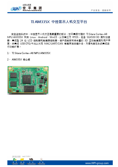
安全监控系统中,中控显示人机交互是最重要的部分,世平集团代理的TI Sitara Cortex-A8 MPU AM335X 支持Linux、Android、WinCE,以及第三方RTOS,包含SGX530 3D 图形加速器,集成型24 位LCD 控制器和触摸屏控制器,使产品能够支持丰富的3D 互动触摸图形用户界面,并集成USB OTG/千兆以太网MAC/UART/CAN 等高灵活关键外设,方便与其他系统集成进行功能扩展。
1、TI Sitara Cortex-A8 MPU AM335X
2、AM335X 核心板
3、AM335X EVM Block Diagram
4、实物
android4.1.2 linux3.2.0 特性:
同时支持android4.1.2和linux3.2.0 特性:
以上TI AM335X 核心板,由世平集团IDH 技术合作伙伴成都嵌智捷科技有限公司()提供,AM335X 开发板,由世平集团提供。
AM335x ARM Cortex-A8核心板中文资料
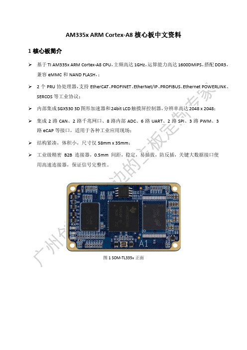
AM335x ARM Cortex-A8核心板中文资料1核心板简介➢基于TI AM335x ARM Cortex-A8 CPU,主频高达1GHz,运算能力高达1600DMIPS,搭配DDR3,兼容eMMC和NAND FLASH,;➢2个PRU协处理器,支持EtherCAT、PROFINET、EtherNet/IP、PROFIBUS、Ethernet POWERLINK、SERCOS等工业协议;➢内部集成SGX530 3D图形加速器和24bit LCD触摸屏控制器,分辨率高达2048 x 2048;➢集成2路CAN、2路千兆网口、8路内部ADC、6路UART、2路SPI、3路PWM、3路eCAP等接口,适用于各种工业应用现场;➢结构紧凑,体积小,尺寸仅58mm x 35mm;➢工业级精密B2B 连接器,0.5mm 间距,稳定,易插拔,防反插,关键大数据接口使用高速连接器,保证信号完整性。
图1 SOM-TL335x正面图2 SOM-TL335x背面由广州创龙自主研发的SOM-TL335x是体积极小的AM335x Cortex-A8工业级核心板。
采用沉金无铅工艺的八层板设计,专业的PCB Layout保证信号完整性的同时,经过严格的质量控制,满足工业各种极端环境应用,不仅提供丰富的Demo程序,还提供详细的开发教程,协助进行底板设计和调试以及软件开发。
2典型运用领域●工业及楼宇自动化●消费类医疗器械●机器人●智能收费系统●充电桩计费控制单元●称重系统●电力仪表3软硬件参数系统框图图3 AM335x功能框图软件参数表 2(2)系统烧写镜像、内核驱动源码、文件系统源码,以及丰富的Demo程序;(3)完整的平台开发包、入门教程,节省软件整理时间,上手容易;(4)基于广州创龙AM335x开发板的Qt界面开发教程;开发例程主要包括:➢TI-RTOS开发例程➢Linux开发例程➢Qt开发例程➢PRU开发例程图5 SOM-TL335x机械尺寸图。
