rsa6.1j4
二极管选型——精选推荐
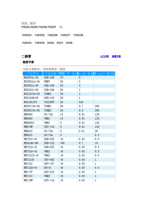
26.190 23.720
21.540
19.520 17.560 15.850 14.340 12.910 11.740 10.760 9.770 8.850 8.020 7.280 6.650 6.060 5.490 4.980 4.550 4.170 3.890 3.600 35.360 32.790 30.320 27.700 24.970 22.610 20.640 18.630 16.820 15.250 13.890 12.550 11.440 10.500 9.410 8.570 7.780
SOT-323 40
SOT-323 45
S0T-346 45
S0T-346 40
S0D-323 30
TUMD2
30
TSMD5
30
SOT-416 30
SOT-416 30
SOT-363 30
SOT-363 30
SOD-523 45
SOD-523 30
VMD2
30
VMN2
30
SOD-523 40
VMN2
0.5
50
RB225T100
T O220FN 100
30
400
RB225T-60
T O220FN 60
30
600
RB215T-90
T O220FN 90
20
400
RB215T-60
T O220FN 60
20
600
RB215T-40
T O220FN 40
20
500
RB205T-90
T O220FN 90
6
160
RB095T-60
T O220FN 60
信息安全工程师案例分析真题考点:RSA密钥长度、明文长度和密文长度

信息安全工程师案例分析真题考点:RSA密钥长度、明
文长度和密文长度
目前主流密钥长度至少都是1024bits以上,低于1024bit的密钥已经不建议使用(安全问题)
RSA算法本身要求加密内容也就是明文长度m必须0<m<n,也就是说内容这个大整数不能超过n,否则就出错。
< p=""></m<n,也就是说内容这个大整数不能超过n,否则就出错。
<>
密文长度就是给定符合条件的明文加密出来的结果位长,这个可以确定,加密后的密文位长跟密钥的位长度是相同的。
对明文进行比特串分组,使得每个分组对应的十进制数小于n,然后依次对每个分组m做一次加密,所有分组的密文构成的序列就是原始消息的加密结果,即m满足0<=m<n,则加密算法为:< p=""></n,则加密算法为:<> c≡m^e mod n; c为密文,且0<=c<n。
< p=""></n。
<>
相关真题:2020年信息安全工程师下午案例分析真题,第二大题,问题6【在RSA密码中,消息m的取值有什么限制?】。
RSA加密算法的基本原理

RSA加密算法的基本原理首先,我们需要理解两个基本概念:公钥和私钥。
在RSA算法中,公钥是可以公开的,用于加密数据,而私钥是保密的,用于解密数据。
RSA算法的基本原理如下:1.选择两个不相等的大素数p和q,计算n=p*q。
这个n就是我们所谓的RSA模数,它将作为公钥和私钥的一部分。
2.计算欧拉函数φ(n)=(p-1)*(q-1),欧拉函数表示小于n且与n互质的正整数的个数。
3.选择一个整数e,使得1<e<φ(n)且e与φ(n)互质。
e就是我们所谓的加密指数,它将作为公钥的一部分。
4.计算e关于φ(n)的模反元素d,即满足(d*e)%φ(n)=1的整数d。
d就是我们所谓的解密指数,它将作为私钥的一部分。
5.公钥由模数n和加密指数e组成,私钥由模数n和解密指数d组成。
6.假设要加密的明文为M,加密后得到密文C,那么加密的过程可以用公式C=M^e%n来表示。
这个过程中,e和n是公钥的一部分。
7.假设要解密的密文为C,解密后得到明文M,那么解密的过程可以用公式M=C^d%n来表示。
这个过程中,d和n是私钥的一部分。
对于一个需要使用RSA加密的通信双方,可以通过公开自己的公钥和自己保留的私钥来实现加密和解密的过程。
发送方使用接收方的公钥来加密消息,并将加密后的消息发送给接收方。
接收方则使用自己的私钥来解密接收到的消息。
在整个过程中,只需要保护好私钥的安全性,就可以确保通信过程的安全性。
即使公钥被截获,攻击者也无法通过公钥本身来计算出私钥。
总结来说,RSA加密算法的基本原理就是利用大素数分解困难和欧拉函数计算的性质,通过公钥和私钥的配对来实现加密和解密的过程。
这种非对称加密算法能够在保证安全性的同时方便地实现安全通信。
rsa算法原理
rsa算法原理
RSA算法原理。
RSA算法是一种非对称加密算法,它的安全性基于大数分解的困难性。
RSA
算法的原理主要涉及到两个大素数的选择、密钥的生成、加密和解密过程。
首先,我们需要选择两个大素数p和q,它们的乘积n就是RSA算法中的模数。
然后,我们计算n的欧拉函数φ(n)=(p-1)(q-1)。
接下来,我们选择一个整数e,使
得e和φ(n)互质,并且1<e<φ(n)。
e就是公钥中的指数。
然后,我们计算e的模
φ(n)的逆元d,d就是私钥中的指数。
有了公钥(e, n)和私钥(d, n)之后,我们就可以进行加密和解密操作了。
假设我
们有一段明文M,它的长度不超过n。
加密过程就是将明文M的e次方对n取模
得到密文C,C≡M^e(mod n)。
解密过程就是将密文C的d次方对n取模得到明文M,M≡C^d(mod n)。
RSA算法的安全性基于大数分解的困难性。
也就是说,如果我们能够迅速地分解n为p和q的乘积,那么我们就可以很容易地计算出φ(n),从而得到私钥d。
但是,目前没有有效的算法能够在合理的时间内对大数进行分解,这就保证了RSA
算法的安全性。
总的来说,RSA算法的原理包括了大素数的选择、密钥的生成、加密和解密过程。
通过合理选择大素数,并根据其生成公钥和私钥,我们可以实现安全可靠的加密和解密操作。
RSA算法已经被广泛应用于互联网通信、数字签名、数据加密等
领域,成为了当今世界上最重要的非对称加密算法之一。
rsa公钥固定值

rsa公钥固定值RSA公钥加密是一种非对称加密算法,它使用两个不同的密钥:公钥和私钥。
其中,公钥可以被用于加密数据,而私钥则用于解密已加密的数据。
首先,我们需要了解一下RSA算法的基本原理。
RSA算法是根据两个大素数相乘的乘积难以分解为质因数的特性而设计的。
公钥由两个部分组成,即模数n和指数e。
私钥也由两个部分组成,即模数n和指数d。
其中,模数n是两个素数的乘积,而指数e和d则满足e * d = 1 mod φ(n),其中φ(n)是n的欧拉函数值。
RSA公钥的固定值通常是由算法的设计者或者标准化组织指定的。
这样做的目的是确保公钥的安全性和一致性。
如果公钥是由用户自行生成,那么可能会存在安全隐患,例如可能会使用弱密码或者使用非随机生成的素数。
固定公钥的使用也便于双方在进行通信时能够互相识别对方的身份。
此时,一个人可以将自己的公钥发布给其他人,而其他人可以使用该公钥加密数据,然后再将加密后的数据发送给该人。
只有该人才能使用自己的私钥解密该数据,其他人无法解密。
另外,固定公钥还有助于保护数据的完整性和机密性。
通过使用公钥加密数据,可以防止未经授权的人通过窃听等手段获取到原始数据。
同时,私钥的保护也是非常重要的,因为只有拥有正确的私钥才能解密加密后的数据。
在实际应用中,RSA公钥加密已经被广泛应用于安全通信、数字签名、加密存储等领域。
它在保护数据传输的过程中发挥着重要作用。
不过,需要注意的是,RSA算法在加密和解密过程中非常耗时,因此在处理大量数据时可能会存在一定的性能问题。
总结来说,RSA公钥固定值保证了公钥的一致性和安全性,使得双方能够互相识别对方的身份。
同时,它还能够保护数据的完整性和机密性。
RSA公钥加密在实际应用中发挥着重要作用,但需要注意性能问题。
rsa算法例题讲解

rsa算法例题讲解rsa算法例题讲解RSA算法是一种基于公钥加密和私钥解密的加密算法,被广泛用于数字签名、消息认证码和密钥交换等领域。
下面将介绍RSA算法的基本概念、加密原理和例题分析。
一、RSA算法的基本概念RSA算法是由R扎米亚斯和郑希威于1976年提出的,它基于大素数的分解问题,利用两个大素数p和q的乘积n和e作为公钥和私钥,通过私钥进行加密和解密操作。
其中,e是RSA算法中的重要参数,它决定了RSA算法的加密强度。
RSA算法的基本流程如下:1. 计算n和e:n是公钥的大小,e是私钥的大小。
2. 计算p和q:p和q是两个大素数,它们的乘积为n。
3. 计算d和d":d是p和q中较小的一个数,d"是(n-e) mod p。
4. 计算s和s":s是(e mod p) ^ d mod q,s"是(s^e mod q) mod p。
5. 计算f和g:f和g是满足以下条件的两个整数:(1) f*g=s"^e mod p,(2) f*g=s^e mod q。
6. 计算c和c":c是f mod p和g mod q。
7. 加密操作:将明文m转换为整数,计算c^m mod p和(c^m)^e mod q,得到密文c"。
8. 解密操作:将密文c"转换为明文m,计算((c^m)^e mod q)^d mod p,得到明文m。
二、RSA算法的加密原理RSA算法的加密原理是利用两个大素数的乘积n和e作为公钥和私钥,通过私钥进行加密和解密操作。
在加密过程中,明文m被转换为整数,然后计算密文c"的值。
根据RSA算法的公式,((c^m)^e mod q)^d mod p=c^((m mod q)^e mod p),因此可以通过计算c的值,将明文m转换为密文c"。
三、RSA算法的例题分析下面是一些RSA算法例题的分析:1. 计算e:- 42- 3- 5- 17- 23根据RSA算法的公式,e=((p-1)*(q-1)/2) mod (p-1)*(q-1)。
RSA算法和实现及实例

RSA算法和实现及实例<一>基础RSA算法非常简单,概述如下:找两素数p和q取n=p*q取t=(p-1)*(q-1)取任何一个数e,要求满足e<t并且e与t互素(就是最大公因数为1)取d*e%t==1这样最终得到三个数:n d e设消息为数M (M <n)设c=(M**d)%n就得到了加密后的消息c设m=(c**e)%n则m == M,从而完成对c的解密。
注:**表示次方,上面两式中的d和e可以互换。
在对称加密中:n d两个数构成公钥,可以告诉别人;n e两个数构成私钥,e自己保留,不让任何人知道。
给别人发送的信息使用e加密,只要别人能用d解开就证明信息是由你发送的,构成了签名机制。
别人给你发送信息时使用d加密,这样只有拥有e的你能够对其解密。
rsa的安全性在于对于一个大数n,没有有效的方法能够将其分解从而在已知n d的情况下无法获得e;同样在已知n e的情况下无法求得d。
或者说,rsa的安全性在于对于一个大数n,没有有效的办法将其分解成p和q。
<二>实践接下来我们来一个实践,看看实际的操作:找两个素数:p=47q=59这样n=p*q=2773t=(p-1)*(q-1)=2668取e=63,满足e<t并且e和t互素用perl简单穷举可以获得满主e*d%t ==1的数d:C:\Temp>perl -e "foreach $i (1..9999){ print($i),last if$i*63%2668==1 }"847即d=847最终我们获得关键的n=2773d=847e=63取消息M=244我们看看加密:c=M**d%n = 244**847%2773用perl的大数计算来算一下:C:\Temp>perl -Mbigint -e "print 244**847%2773"465即用d对M加密后获得加密信息c=465解密:我们可以用e来对加密后的c进行解密,还原M:m=c**e%n=465**63%2773 :C:\Temp>perl -Mbigint -e "print 465**63%2773"244即用e对c解密后获得m=244 , 该值和原始信息M相等。
rsa算法的基本思路

rsa算法的基本思路RSA算法是一种非对称加密算法,其基本思路是利用两个大素数及其乘积的性质,实现公钥加密和私钥解密。
RSA算法的基本步骤如下:1.选择两个大素数p和q。
这两个素数要尽可能地大,以增加算法的安全性。
同时,p和q不能相等。
2.计算p和q的乘积n。
n作为RSA算法的模数。
n = p * q3.计算n的欧拉函数φ(n)。
φ(n) = (p-1) * (q-1)欧拉函数φ(n)表示小于n且与n互质的正整数的个数。
在RSA算法中,φ(n)是p和q的乘积减去p和q各自减1。
由于p和q都是素数,所以它们的因数只有1和它们本身。
4.选择一个大于1且小于φ(n)的整数e,使得e与φ(n)互质。
e 作为公钥中的指数。
通常情况下,选择65537作为公钥指数e,因为65537是一个较大的质数,并且其二进制表示为“10000000000000001”,只包含很少的1,加快了加密运算。
5.计算满足以下条件的整数d:(e * d) mod φ(n) = 1d作为私钥中的指数。
我们可以使用扩展欧几里得算法来求解d的值。
扩展欧几里得算法可以求解形如ax + by = gcd(a, b)的线性同余方程。
6.公钥由(n, e)组成,私钥由(n, d)组成。
7.加密过程对于明文M,将其转换为整数m,满足0 <= m < n。
加密:C = M^e mod n加密后的密文C为整数。
8.解密过程解密:M = C^d mod n解密后的明文M为整数,可以重新转换为原文。
RSA算法的安全性依赖于两个大素数p和q的选取和私钥d的保密性。
如果有人能够分解n为p和q的乘积,那么就可以计算出φ(n),从而推导出私钥d。
因此,RSA算法的安全性依赖于大素数分解的难度。
总的来说,RSA算法是一种非对称加密算法,通过利用大素数的性质,实现了公钥加密和私钥解密。
其基本思路是选择两个大素数p和q,计算n和φ(n),选择公钥指数e和私钥指数d,最后进行加密和解密操作。
艾诺综合测试仪用户手册
4.4 选择测试组 ...........................................................................................14 4.5 设置测试项 ...........................................................................................14 4.6 接地导通电阻测试 ...............................................................................16
1.6.1 禁止操作......................................................................................................... 3 1.6.2 测试中注意事项............................................................................................. 3
4.6.1 设置接地导通电阻测试项........................................................................... 16 4.6.2 启动接地导通电阻测试............................................................................... 16
4.7
绝缘电阻测试 .......................................................................................17
sa算法及安全性分析(2)

如果用MIPS年表示每秒钟执行一百万条指令 的计算机计算一年时间的计算量,下表给出了不同 比特 1024比特 2048比特
MIPS年
3104
2 108 31011 31020
RSA算法的安全性分析
为了抵抗现有的整数分解算法,对RSA模n的素因子 p和q还有如下要求(即是强素数):
RSA算法举例
▪ 设 p=7, q=17, n=7*17=119; 参数T={n=119};
▪ φ(n)=(7-1)(17-1)=96;
▪ 选择e=5, gcd(5,96)=1;
公钥pk=5;
▪ 计算d, ( d*e) mod 96=1; d=77; 私钥sk=77;
设:明文m=19
加密:(19)5 mod 119 = 66
Euler 函数
▪ 所有模m和r同余的整数组成剩余类[r] ▪ 剩余类[r]中的每一个数和m互素的充要条件是r和m互素 ▪ 和m互素的同余类数目用φ(m)表示,称m的Euler函数 ▪ 当m是素数时,小于m的所有整数均与m互素,因此
φ(m)=m-1
▪ 对n=pq, p和q 是素数,φ(n)=φ(p)φ(q)=(p-1)(q-1)
脱密:(66)77 mod 119 = 19
RSA算法的安全性分析
▪ 密码分析者攻击RSA体制的关键点在于如何分解n ▪ 若分解成功使n=pq,则可以算出φ(n)=(p-1)(q-1),
然后由公开的e,解出秘密的d
▪ 若使RSA安全,p与q必为足够大的素数,使分析者
没有办法在多项式时间内将n分解出来 n 取 1024 位 或 取 2048 位 , 这 样 p 、 q 就 应 该 取
512位和1024位。
RSA算法的安全性分析
TPS2590 热插拔控制器评估模块用户手册说明书

User's GuideSLUU373A–July2009–Revised June2014 TPS2590Hot Swap Controller Evaluation ModuleThis user’s guide describes the setup and operation of the TPS2590evaluation module.Contents1Introduction (2)2Description (2)2.1Applications (2)2.2Features (2)3EVM Block Diagram (3)4Schematic (4)5Bill of Materials (5)6EVM PCB Layout (6)7Circuit Description (8)7.1Test Points (8)7.2Connectors (8)7.3Jumpers (8)7.4Switches (8)8EVM Test Setup (9)8.1Test Equipment (9)8.2Equipment Supplied (9)8.3Recommended Test Setup (9)8.4Operation (10)9Test Results (10)List of Figures1TPS2590EVM Block Diagram (3)2TPS2590EVM Schematic (4)3Component Placement(Top View) (6)4Board Layout(Top View) (6)5Board Layout(Bottom View) (7)6Component Placement(Bottom View) (7)7Equipment Connections (9)8Example Scope Trace (10)List of Tables1TPS2590EVM Bill of Materials (5)2Test Points (8)3Connectors (8)4Jumpers (8)5EVM Configurations (9)1 SLUU373A–July2009–Revised June2014TPS2590Hot Swap Controller Evaluation Module Submit Documentation FeedbackCopyright©2009–2014,Texas Instruments IncorporatedIntroduction 1IntroductionThis user’s guide describes the features of the TPS2590EVM.The TPS2590schematic,printed-circuit board(PCB)layout,and bill of materials(BOM)are provided as well as a setup and getting started.2DescriptionThe EVM is a3-to18-V module using the TPS2590or TPS2591hot swap controller with integratedMOSFET.At power on,the output is power limited to control inrush current and protect the MOSFET.On an overcurrent condition,the controller interrupts power to the load at high speed and signals load status.Operating current,fault current and fault timer settings are hardware programmable.2.1ApplicationsServer:•Plug-in Circuit Boards•RAID/Disk DriveTelecom:•ATCA•Micro-ATCAGeneral Hot Plug2.2Features•3-to20-V operation•Controlled inrush current•Fast circuit breaker control•Hardware programmable–Operating current–Fault current–Fault timer to avoid nuisance tripping–Latch off or retry.TPS2590is pin selectable•LED status display•A slide switch controls the ENABLE signal•The area under the TPS2590is copper pour with vias to the internal ground to take advantage of the power pad package•On-board transorb for overvoltage input protection•A common diode at the output prevents a negative spike if the load is removed while powered on•Test points available to monitor circuit operation•Design Calculator Tool(/product/TPS2590/toolssoftware)All trademarks are the property of their respective owners.2TPS2590Hot Swap Controller Evaluation Module SLUU373A–July2009–Revised June2014Submit Documentation FeedbackCopyright©2009–2014,Texas Instruments Incorporated EVM Block Diagram3EVM Block DiagramFigure 1shows the EVM block diagram.Figure 1.TPS2590EVM Block Diagram3SLUU373A–July 2009–Revised June 2014TPS2590Hot Swap Controller Evaluation ModuleSubmit Documentation FeedbackCopyright ©2009–2014,Texas Instruments Incorporated Bill of Materials 5Bill of MaterialsTable1lists the BOM for the EVM.Table1.TPS2590EVM Bill of MaterialsCount RefDes Value Description Size Part Number MFR2C1,C30.1uF Capacitor Ceramic,25V,X7R,10%0603STD muRata1C21000pF Capacitor,Ceramic,25V,X7R,20%0603STD muRata1C4.56uF Capacitor,Ceramic,10V,X7R,10%0805STD muRata1C51uF Capacitor,Ceramic,25V,X7R,20%1206STD muRata1C6.1uF Capacitor Ceramic,25V,X7R,10%0603STD muRata1D1LN1271R Diode,LED,Red,20-mA,0.9-mcd0.068x0.049inch LN1271R Panasonic1D2MMBZ522Diode,Zener,4.3V,350mW SOT23MMBZ5229B Motorola9B1D3SMAJ18A Diode,SMT TVS400W,1-A,18V SMA SMAJ18A Diodes1D4MBR130L Diode,Schottky,1000-mA,30-V SOD123MBR130LSFT1STDSFT14J1,J2,J4,7693Screw Terminal0.310x0.310inch7693Keystone J51J3PEC02SA Header,2-pin,100mil spacing0.100inch x2PEC02SAAN SullinsAN1Q1MMBT390Bipolar,PNP,40-V,200-mA,225-mW SOT23MMBT3906LT1On Semi6LT11R10Resistor,Chip,1/16W,1%0603STD Vishay1R2499Resistor,Chip,.5W,1%2512STD STD1R310K Resistor,Chip,1/16W,5%0603STD Vishay1R41K Resistor,Chip,1/16W,1%0603STD Vishay1R510K Resistor,Chip,1/16W,1%0603STD Vishay1R620K Resistor,Chip,1/16W,5%0603STD Vishay1R7300Resistor,Chip,1/10W,5%0805STD Vishay1R840.2K Resistor,Chip,1/16W,1%0603STD Vishay1R949.9K Resistor,Chip,1/16W,1%0603STD Vishay1S109-03201-Switch,SPDT,Slide,PC-mount,500-mA0.400x0.100inch09-03201-02EAO027TP1,TP2,5012Test Point,White,Thru Hole0.125x0.125inch5012Keystone TP3,TP4,TP5,TP6,TP94TP10,GND Test Point,SM,0.150x0.0900.185x0.135inch5016Keystone TP11,TP12,TP134TP7,TP8,Test Point,0.062Hole0.250inch5012Keystone TP14,TP151U1TPS2590IC,3V to20V Integrated FET Load Switch QFN-16TPS2590RSA TIRSA5 SLUU373A–July2009–Revised June2014TPS2590Hot Swap Controller Evaluation Module Submit Documentation FeedbackCopyright©2009–2014,Texas Instruments IncorporatedEVM PCB Layout 6EVM PCB LayoutFigure3through Figure6illustrate the board outline drawings.ponent Placement(Top View)Figure4.Board Layout(Top View)6TPS2590Hot Swap Controller Evaluation Module SLUU373A–July2009–Revised June2014Submit Documentation FeedbackCopyright©2009–2014,Texas Instruments Incorporated EVM PCB LayoutFigure5.Board Layout(Bottom View)ponent Placement(Bottom View)7 SLUU373A–July2009–Revised June2014TPS2590Hot Swap Controller Evaluation Module Submit Documentation FeedbackCopyright©2009–2014,Texas Instruments IncorporatedCircuit Description 7Circuit Description7.1Test PointsTable2lists the test point descriptions.Table2.Test PointsName DescriptionVIN Input voltage power supply4.3V 4.3-V referenceEN Enable signal,high trueFLT Fault signal,low trueLATCH Latch signal,high true,low for retryVOUT Output voltageCT Fault timer capacitorGND Scope ground test pointGND Scope ground test pointGND Scope ground test pointGND Scope ground test point7.2ConnectorsTable3lists the connector descriptions.Table3.ConnectorsConnector DescriptionJ1Main power input,VINJ2Main power ground,GNDJ4LoadJ5Load ground,GND7.3JumpersR1is used to disconnect the LEDs for test measurement of TPS2590quiescent current.This0-Ωresistor is normally installed.Table4provides the jumper description of jumper J3.Table4.JumpersJumper DescriptionJ3TPS2590Only Off=Latch,On=Retry7.4Switches7.4.1Enable Switch S1The ENABLE slide switch turns on the hot plug controller to ramp the output voltage.When the switch is off,the output is off.7.4.2IndicatorsRed LED indicator for FAULT(FLT).8TPS2590Hot Swap Controller Evaluation Module SLUU373A–July2009–Revised June2014Submit Documentation FeedbackCopyright©2009–2014,Texas Instruments IncorporatedNote:Connects to Scope EVM Test Setup8EVM Test Setup 8.1Test EquipmentVoltage Source:The input voltage source,V IN is a 20-V variable dc source at 10A.Oscilloscope:A digital oscilloscope can be used to monitor the test points.Current Probe:A current probe is helpful to observe turn-on characteristics of the external load.Recommended Wire Gague:Power is limited to 5W;18-gage wire,minimum,is recommended.8.2Equipment SuppliedThe TPS2590EVM module configured with TPS2590is supplied.Table 5.EVM ConfigurationsEvaluation Module Component HPA490EVM-001TPS25908.3Recommended Test SetupFigure 1illustrates the equipment connections for power up and testing.•Connect the positive voltage input power supply to J1and the negative voltage to GND,J2.Connectors J1and J2can accept #6ring or spade lugs.•Connect the RC load at J4and the load return at J5.The example here uses 220µF,15Ω.•Scope to current probe to measure the load current.•Scope the V OUT and EN.Figure 7.Equipment Connections9SLUU373A–July 2009–Revised June 2014TPS2590Hot Swap Controller Evaluation ModuleSubmit Documentation FeedbackCopyright ©2009–2014,Texas Instruments IncorporatedEVM Test Setup 8.4OperationUse the following steps for EVM operation:1.Turn on the power supply.2.Trigger the scope on EN low-going edge.3.Slide the EN to the EN position as screened on the circuit board.9Test ResultsObserve waveforms similar to Figure8.•The current to the load is not constant but increases after the initial inrush.Current is low,initially, because the voltage across the internal MOSFET is initially at its highest level and the controller ispower-limiting the MOSFET.•Although the current limit,IFLT ,is set to4A,the start up current never goes above2.2A because of thepower limiting.However,4A is available to the steady state load when the MOSFET is fully enhanced.•At the end of the capacitor charge time,the current drops to the dc level powering the resistive part of the load,about0.8A.Refer to SLUS960for more details.Figure8.Example Scope Trace10TPS2590Hot Swap Controller Evaluation Module SLUU373A–July2009–Revised June2014Submit Documentation FeedbackCopyright©2009–2014,Texas Instruments Incorporated Revision HistoryRevision HistoryChanges from Original(July2009)to A Revision Page •Added Design Calculator tool and link to the list of features (2)•Changed device name in title of Figure1 (3)•Changed schematic,Figure2 (4)•Changed contents of BOM (5)•Added Component Placement(Bottom View)image (6)•Changed Board Layout(Top View)image (6)•Changed Board Layout(Bottom View)image (7)•Added Component Placement(Bottom View)image (7)•Changed entire content of first paragraph in the Test Points section (8)•Changed R9to R1in first paragraph of Jumpers section (8)11 SLUU373A–July2009–Revised June2014Revision History Submit Documentation FeedbackCopyright©2009–2014,Texas Instruments IncorporatedIMPORTANT NOTICETexas Instruments Incorporated and its subsidiaries(TI)reserve the right to make corrections,enhancements,improvements and other changes to its semiconductor products and services per JESD46,latest issue,and to discontinue any product or service per JESD48,latest issue.Buyers should obtain the latest relevant information before placing orders and should verify that such information is current and complete.All semiconductor products(also referred to herein as“components”)are sold subject to TI’s terms and conditions of sale supplied at the time of order acknowledgment.TI warrants performance of its components to the specifications applicable at the time of sale,in accordance with the warranty in TI’s terms and conditions of sale of semiconductor products.Testing and other quality control techniques are used to the extent TI deems necessary to support this warranty.Except where mandated by applicable law,testing of all parameters of each component is not necessarily performed.TI assumes no liability for applications assistance or the design of Buyers’products.Buyers are responsible for their products and applications using TI components.To minimize the risks associated with Buyers’products and applications,Buyers should provide adequate design and operating safeguards.TI does not warrant or represent that any license,either express or implied,is granted under any patent right,copyright,mask work right,or other intellectual property right relating to any combination,machine,or process in which TI components or services are rmation published by TI regarding third-party products or services does not constitute a license to use such products or services or a warranty or endorsement e of such information may require a license from a third party under the patents or other intellectual property of the third party,or a license from TI under the patents or other intellectual property of TI.Reproduction of significant portions of TI information in TI data books or data sheets is permissible only if reproduction is without alteration and is accompanied by all associated warranties,conditions,limitations,and notices.TI is not responsible or liable for such altered rmation of third parties may be subject to additional restrictions.Resale of TI components or services with statements different from or beyond the parameters stated by TI for that component or service voids all express and any implied warranties for the associated TI component or service and is an unfair and deceptive business practice. TI is not responsible or liable for any such statements.Buyer acknowledges and agrees that it is solely responsible for compliance with all legal,regulatory and safety-related requirements concerning its products,and any use of TI components in its applications,notwithstanding any applications-related information or support that may be provided by TI.Buyer represents and agrees that it has all the necessary expertise to create and implement safeguards which anticipate dangerous consequences of failures,monitor failures and their consequences,lessen the likelihood of failures that might cause harm and take appropriate remedial actions.Buyer will fully indemnify TI and its representatives against any damages arising out of the use of any TI components in safety-critical applications.In some cases,TI components may be promoted specifically to facilitate safety-related applications.With such components,TI’s goal is to help enable customers to design and create their own end-product solutions that meet applicable functional safety standards and requirements.Nonetheless,such components are subject to these terms.No TI components are authorized for use in FDA Class III(or similar life-critical medical equipment)unless authorized officers of the parties have executed a special agreement specifically governing such use.Only those TI components which TI has specifically designated as military grade or“enhanced plastic”are designed and intended for use in military/aerospace applications or environments.Buyer acknowledges and agrees that any military or aerospace use of TI components which have not been so designated is solely at the Buyer's risk,and that Buyer is solely responsible for compliance with all legal and regulatory requirements in connection with such use.TI has specifically designated certain components as meeting ISO/TS16949requirements,mainly for automotive use.In any case of use of non-designated products,TI will not be responsible for any failure to meet ISO/TS16949.Products ApplicationsAudio /audio Automotive and Transportation /automotiveAmplifiers Communications and Telecom /communicationsData Converters Computers and Peripherals /computersDLP®Products Consumer Electronics /consumer-appsDSP Energy and Lighting /energyClocks and Timers /clocks Industrial /industrialInterface Medical /medicalLogic Security /securityPower Mgmt Space,Avionics and Defense /space-avionics-defense Microcontrollers Video and Imaging /videoRFID OMAP Applications Processors /omap TI E2E Community Wireless Connectivity /wirelessconnectivityMailing Address:Texas Instruments,Post Office Box655303,Dallas,Texas75265Copyright©2014,Texas Instruments Incorporated。
激光测径仪操作手册

使用仪器前请详细阅读此手册奥美加科技有限公司AUTO MEASURE GAUGE TECHNOLOGY安全注意事项:◆此产品安装需详细参考本使用手册。
如有不明白请及时联系公司总部或者售后服务部。
◆非专业人员,不得开启产品机盖。
◆此产品电源须接地。
◆不能让激光直射眼睛,以免眼睛受到伤害。
◆定期用干净、柔软的材料轻轻擦拭窗口玻璃,防止过多的灰尘堆积在窗口玻璃上影响仪器正常使用。
mob:153******** QQ:503758071tel:0574-********fax**************目录一、LGD-02XY激光测径仪1、概述 (3)2、技术参数 (3)3、仪器安装 (4)4、显示 (7)5、接口信号 (8)6、参数设定 (9)7、反馈控制 (12)8、通讯 (13)9、校准 (15)10、故障列表 (16)打印机补充手册 (19)一、LGD-02XY激光测径仪1 概述1.1简介LGD系列激光测径仪是我公司引进国外先进技术开发设计并生产的新一代测径仪。
其采用激光扫描技术,具有测量范围大,精度高,使用寿命长,性能稳定等特点。
1.2适用范围主要用于测量各种材料的直径,对各种电线、电缆、漆包线、软管和其它线材进行在线测量和控制。
1.3测试原理:见(图一),由半导体激光器“a”发出激光束,通过电机“c”带动八棱镜“b”高速旋转,将激光器光束扫描通过棱镜“d”转换为平行光通过测试区(GATE),当测试区有被测物“e”时,其会遮挡住部份平行光,并通过聚焦棱镜“f”在光电接收管上转换成低电平;而没有被测物遮挡的平行光则转换为高电平,通过计算低电平的扫描时间,则可计算出被测物在激光束扫描方向的外径值。
(图一)(LGD系列测径仪测量原理)2技术参数2.1、使用条件供电电源 AC220V±10% 50Hz~60Hz功耗≤15W工作温度 5~45℃相对湿度≤80%(无冷凝水)空气中不含腐蚀性气体,油,蒸汽及严重尘埃。
rsa算法原理与素数的应用

RSA算法原理与素数的应用1. 引言RSA算法是一种非常流行的加密算法,常用于数据传输的安全性保障。
其基础原理是利用大素数的乘积难以被分解的特性,实现了公钥加密和私钥解密的过程。
本文将介绍RSA算法的原理,并探讨素数在该算法中的应用。
2. RSA算法原理RSA算法基于公钥密码学,由三个关键要素组成:生成密钥对、加密和解密。
2.1 生成密钥对RSA算法的核心是生成一对公钥和私钥。
步骤如下:1.随机选择两个不同的大素数p和q。
2.计算n = p * q,n作为RSA加密的模数。
3.计算φ(n) = (p - 1) * (q - 1),φ(n)为n的欧拉函数值。
4.选择一个与φ(n)互质的整数e,称为公钥的指数,一般选择65537。
5.计算e的乘法逆元d,即满足(e * d) % φ(n) = 1的整数d,d称为私钥的指数。
6.公钥为(n, e),私钥为(n, d)。
2.2 加密和解密2.2.1 加密给定一段明文M,加密的过程如下:1.将明文M转换为整数m。
2.计算密文C = m^e % n,其中^表示指数操作符。
3.密文C为加密后的结果。
2.2.2 解密给定一个密文C,解密的过程如下:1.计算明文m = C^d % n,其中^表示指数操作符。
2.明文m为解密后的结果。
3. 素数的应用素数在RSA算法中起到了关键作用。
具体体现在以下几个方面:3.1 选择素数在生成密钥对的过程中,选择两个素数p和q是非常重要的。
由于大素数的乘积难以被分解,选择足够大的素数可以增强RSA算法的安全性。
3.2 计算欧拉函数在生成密钥对的步骤中,需要计算n的欧拉函数φ(n)。
由于n是两个大素数的乘积,φ(n) = (p - 1) * (q - 1)。
这个欧拉函数的值在加密和解密过程中起到重要的作用。
3.3 求乘法逆元在生成私钥的指数d时,需要求解e的乘法逆元d。
根据扩展欧几里得算法,可以通过欧拉函数φ(n)和公钥指数e来求解d。
rsa数学原理
rsa数学原理RSA算法作为一种非对称加密算法,被广泛应用于网络安全领域,其核心是基于大整数的数学原理。
下面将对RSA数学原理进行详细阐述。
1. 生成RSA密钥对首先生成RSA密钥对。
这里需要选择两个大质数p和q,然后计算它们的积n=p*q,选取一个整数e,使得它与(p-1)(q-1)互质。
接着计算e关于(p-1)(q-1)的模反元素d,即e*d mod (p-1)(q-1)=1。
这个d就是私钥,(n,e)是公钥。
2. 加密信息假设现在需要加密信息m。
发送方可以使用接收方的公钥(n,e)对m进行加密。
具体方法是将m视为一个整数,并计算出c=m^e mod n。
这个密文c可以传输给接收方。
3. 解密信息接收方收到密文c后,使用自己的私钥d对其进行解密。
具体方法是计算出m=c^d mod n,这个m就是原始信息。
4. 安全性原理RSA算法的安全性依赖于一些数学上困难的问题。
首先,将一个大数分解成质数的因子在计算上非常困难。
其次,通过e和(p-1)(q-1)推出d也是困难的。
因此,破解RSA算法需要解决这些问题,构成了著名的RSA问题。
目前没有任何已知的算法可以高效地解决RSA问题,因此RSA算法是安全的。
总之,RSA算法作为一种经典的非对称加密算法,其安全性得到了广泛认可。
其基本思想是利用大质数的一些数学性质,需要密钥的生成、信息的加密解密等多个步骤。
在当今信息化时代,保护数据安全非常重要,RSA算法的应用前景也将越来越广泛。
TPS2590 Hot Swap Controller System Test Board用户指南说

Using the TPS2590EVM User's GuideLiterature Number:SLUU373July20091Introduction2Description2.1Applications2.2FeaturesUser's GuideSLUU373–July 2009This User’s Guide describes the setup and operation of the TPS2590System Test Board.This User’s Guide describes the features of the TPS2590EVM.The TPS2590schematic,layout and List of Materials are provided as well as a setup and getting started.The EVM is a 3-V to 18-V module using the TPS2590/91hot-swap controller with integrated MOSFET.At power on,the output is power limited to control inrush current and protect the MOSFET.On anover-current condition,the controller interrupts power to the load at high speed and signals load status.Operating current,fault current and fault timer settings are hardware programmable.•Server–Plug-in Circuit Boards –RAID /Disk Drive •Telecom –ATCA–Micro-ATCA •General Hot Plug•3-V to 20-V Operation •Controlled Inrush Current •Fast Circuit Breaker Control •Hardware Programmable –Operating Current –Fault Current–Fault Timer to Avoid Nuisance Tripping–Latch Off or Retry.TPS2590is Pin Selectable •LED Status Display•A Slide Switch Controls the ENABLE Signal.•Copper Pour with Vias to the Internal Ground takes Advantage of the Power Pad Package •On-Board Transorb is for Over-Voltage Input Protection•Common Diode at Output Prevents Negative Spike when Load is Removed While Powered On •Monitor Circuit Operation Test PointsTPS2590Hot Swap Controller System Test Board2SLUU373–July 2009Submit Documentation Feedback EVM Block Diagram 3EVM Block DiagramFigure1.PR893E1EVM Block DiagramSLUU373–July2009TPS2590Hot Swap Controller System Test Board3 Submit Documentation FeedbackSchematic 4SchematicFigure2.PR893E1Schematic,TPS2590EVM4SLUU373–July2009 TPS2590Hot Swap Controller System Test BoardSubmit Documentation Feedback List of Materials 5List of MaterialsTable1.TPS2540EVM List of MaterialsCOUNT REF DES DESCRIPTION PART NUMBER MFR 2C1,C3Capacitor,ceramic,0.1µF,603STD muRata1C2Capacitor,ceramic,1000pF,603STD muRata1C4Capacitor,ceramic,10V,0.56µF,805STD muRata1C5Capacitor,ceramic,25V,1µF,1206STD muRata1C6Capacitor,ceramic,0.1µF,603STD muRata1D1Diode,LED,red,20mA,0.9mcd,0.068x0.049inch LN1271R Panasonic1D3Diode,Zener,4.3V,300mW,SOT23MMBZ5229B Motorola1D4Diode,SMT TVS400W,1A,18V,SMA SMAJ15A Diodes1D5Diode,Schottky,1000mA,30V,SOD123MBR130LSFT1STD4J1,J2,J4,J5Screw terminal,0.310x0.310inch7693KeystoneHeader,2pin,100-mil spacing,(36-pin strip),0.1002J3,J6PTC36SAAN Sullinsinch x21Q1Bipolar,PNP,xx-V,yy-mA,zz-W,SOT23MMBT3906LT1On Semi1R1Resistor,chip,0.5W,1%,499Ω,2512STD STD1R12Resistor,chip,1/16W,1%,40.2kΩ,603STD Vishay1R13Resistor,chip,1/16W,1%,49.9kΩ,603STD Vishay1R2Resistor,chip,1/16W,5%,10kΩ,603STD Vishay1R4Resistor,chip,1/16W,1%,1kΩ,603STD Vishay1R7Resistor,chip,1/16W,5%,20kΩ,603STD Vishay1R8Resistor,chip,1/10W,5%,300,805STD VishaySwitch,SPDT,slide,PC mount,500mA,0.400x0.10009-03201-021S1EAOinch1TP1Test point,white,thru hole,V IN,0.125x0.125inch5012KeystoneTP10,TP11,4Test Point,SM,0.150x0.090,GND,0.185x0.135inch5016Keystone TP12,TP131TP2Test point,white,thru hole,4.3V,0.125x0.125inch5012Keystone1TP3Test point,white,thru hole,EN,0.125x0.125inch5012Keystone1TP4Test point,white,thru hole,FLT,0.125x0.125inch5012Keystone1TP7Test point,white,thru hole,LATCH,0.125x0.125inch5012Keystone1TP8Test point,white,thru hole,V OUT,0.125x0.125inch5012Keystone1TP9Test point,white,thru hole,C T,0.125x0.125inch5012Keystone1U10V to12V Integrated FET Hot Swap,QFN-16TPS2590RSA TISLUU373–July2009TPS2590Hot Swap Controller System Test Board5 Submit Documentation FeedbackBoard Outlines 6Board OutlinesFigure3.Board Outline(TOP)Figure4.Board Outline(BOTTOM)6SLUU373–July2009 TPS2590Hot Swap Controller System Test BoardSubmit Documentation Feedback Board Outlines 6.1Test PointsTest Points TP14,TP15,TP16,TP17,are not installed.These are placed on the board unmarked near Load and Load Return.This is a user option to hardwire additional capacitors,etc to the output.Table2.Test PointsNAME DESCRIPTIONVIN Input voltage power supply4.3V 4.3-V referenceEN Enable signal,high trueFLT Fault signal,low trueLATCH Latch signal,high true,low for retryVOUT Output voltageCT Fault timer capacitorGND Scope ground test pointGND Scope ground test pointGND Scope ground test pointGND Scope ground test point6.2ConnectorsTable3.ConnectorsCONNECTOR DESCRIPTIONJ1Main Power Input,VINJ2Main Power Ground,GNDJ4LoadJ5Load Ground,GND6.3JumpersR9is used to disconnect the LEDs for test measurement of TPS2590quiescent current.This0-Ωresistor is normally installed.Table4.JumpersJUMPER DESCRIPTIONJ3TPS2590Only Off=Latch,On=Retry6.4Switches6.4.1Enable Switch S1The Enable slide switch turns on the hot plug controller to ramp the output voltage.When the switch is off, the output is off.6.5IndicatorsRed LED indicator for FAULT(FLT)SLUU373–July2009TPS2590Hot Swap Controller System Test Board7 Submit Documentation FeedbackEquipment Needed 7Equipment Needed7.1Voltage SourceThe input voltage source,VIN is a20-V variable dc source at10A.7.2OscilloscopeA digital oscilloscope can be used to monitor the test points.7.3Current ProbeA current probe is helpful to observe turn on characteristics of the external load.7.4Recommended Wire GaguePower is limited to5W;18-gage wire minimum is recommended.8Equipment SuppliedThe TPS2590Module configured with TPS2590is supplied.Table5.EVM ConfigurationsEVALUATION MODULE COMPONENTHPA490EVM-001TPS25908TPS2590Hot Swap Controller System Test Board SLUU373–July2009Submit Documentation Feedback9Getting Started (Example)9.1Equipment ConnectionsNote:Connects to Scope9.2Operation Getting Started (Example)Reference Figure 5.•Input power supply positive voltage to J1and negative voltage to GND,J2.Connectors J1and J2can accept #6ring or spade lugs.•RC load at J4and the load return at J5.The example here uses 220µF,15Ω.•Scope to current probe to measure the load current.•Scope the V OUT and EN.Figure 5.Equipment Connections•Turn on the power supply.•Trigger the scope on EN low going edge.•Slide the EN to the EN position as screened on the circuit board.SLUU373–July 2009TPS2590Hot Swap Controller System Test Board 9Submit Documentation FeedbackGetting Started(Example) 9.3Test ResultsObserve waveforms similar to Figure6.•The current to the load is not constant but increases after the initial inrush.Current is low initially because the voltage across the internal MOSFET is initially at its highest level and the controller ispower limiting the MOSFET.•Although the current limit,I FLT,is set to4A,the start up current never goes above2.2A because of the power limiting.However,4A is available to the steady state load when the MOSFET is fullyenhanced.•At the end of the capacitor charge time,the current drops to the DC level powering the resistive part of the load,about0.8A.Figure6.Example Scope Trace10SLUU373–July2009 TPS2590Hot Swap Controller System Test BoardSubmit Documentation Feedback Getting Started(Example)EVALUATION BOARD/KIT IMPORTANT NOTICETexas Instruments(TI)provides the enclosed product(s)under the following conditions:This evaluation board/kit is intended for use for ENGINEERING DEVELOPMENT,DEMONSTRATION,OR EVALUATIONPURPOSES ONLY and is not considered by TI to be a finished end-product fit for general consumer use.Persons handling theproduct(s)must have electronics training and observe good engineering practice standards.As such,the goods being provided are not intended to be complete in terms of required design-,marketing-,and/or manufacturing-related protective considerations,including product safety and environmental measures typically found in end products that incorporate such semiconductorcomponents or circuit boards.This evaluation board/kit does not fall within the scope of the European Union directives regarding electromagnetic compatibility,restricted substances(RoHS),recycling(WEEE),FCC,CE or UL,and therefore may not meet the technical requirements of these directives or other related directives.Should this evaluation board/kit not meet the specifications indicated in the User’s Guide,the board/kit may be returned within30 days from the date of delivery for a full refund.THE FOREGOING WARRANTY IS THE EXCLUSIVE WARRANTY MADE BYSELLER TO BUYER AND IS IN LIEU OF ALL OTHER WARRANTIES,EXPRESSED,IMPLIED,OR STATUTORY,INCLUDING ANY WARRANTY OF MERCHANTABILITY OR FITNESS FOR ANY PARTICULAR PURPOSE.The user assumes all responsibility and liability for proper and safe handling of the goods.Further,the user indemnifies TI from all claims arising from the handling or use of the goods.Due to the open construction of the product,it is the user’s responsibility to take any and all appropriate precautions with regard to electrostatic discharge.EXCEPT TO THE EXTENT OF THE INDEMNITY SET FORTH ABOVE,NEITHER PARTY SHALL BE LIABLE TO THE OTHER FOR ANY INDIRECT,SPECIAL,INCIDENTAL,OR CONSEQUENTIAL DAMAGES.TI currently deals with a variety of customers for products,and therefore our arrangement with the user is not exclusive.TI assumes no liability for applications assistance,customer product design,software performance,or infringement ofpatents or services described herein.Please read the User’s Guide and,specifically,the Warnings and Restrictions notice in the User’s Guide prior to handling theproduct.This notice contains important safety information about temperatures and information on TI’senvironmental and/or safety programs,please contact the TI application engineer orNo license is granted under any patent right or other intellectual property right of TI covering or relating to any machine,process,or combination in which such TI products or services might be or are used.FCC WarningThis evaluation board/kit is intended for use for ENGINEERING DEVELOPMENT,DEMONSTRATION,OR EVALUATIONPURPOSES ONLY and is not considered by TI to be a finished end-product fit for general consumer use.It generates,uses,and can radiate radio frequency energy and has not been tested for compliance with the limits of computing devices pursuant to part15 of FCC rules,which are designed to provide reasonable protection against radio frequency interference.Operation of thisequipment in other environments may cause interference with radio communications,in which case the user at his own expense will be required to take whatever measures may be required to correct this interference.EVM WARNINGS AND RESTRICTIONSIt is important to operate this EVM within the input voltage range and output voltage range of3VDC to18VDC.Exceeding the specified input range may cause unexpected operation and/or irreversible damage to the EVM.If there arequestions concerning the input range,please contact a TI field representative prior to connecting the input power.Applying loads outside of the specified output range may result in unintended operation and/or possible permanent damage to the EVM.Please consult the EVM User's Guide prior to connecting any load to the EVM output.If there is uncertainty as to the load specification,please contact a TI field representative.During normal operation,some circuit components may have case temperatures greater than85°C.The EVM is designed tooperate properly with certain components above as long as the input and output ranges are maintained.These components include but are not limited to linear regulators,switching transistors,pass transistors,and current sense resistors.These types of devices can be identified using the EVM schematic located in the EVM User's Guide.When placing measurement probes near thesedevices during operation,please be aware that these devices may be very warm to the touch.Mailing Address:Texas Instruments,Post Office Box655303,Dallas,Texas75265Copyright2009,Texas Instruments IncorporatedSLUU373–July2009TPS2590Hot Swap Controller System Test Board11 Submit Documentation FeedbackIMPORTANT NOTICETexas Instruments Incorporated and its subsidiaries(TI)reserve the right to make corrections,modifications,enhancements,improvements, and other changes to its products and services at any time and to discontinue any product or service without notice.Customers should obtain the latest relevant information before placing orders and should verify that such information is current and complete.All products are sold subject to TI’s terms and conditions of sale supplied at the time of order acknowledgment.TI warrants performance of its hardware products to the specifications applicable at the time of sale in accordance with TI’s standard warranty.Testing and other quality control techniques are used to the extent TI deems necessary to support this warranty.Except where mandated by government requirements,testing of all parameters of each product is not necessarily performed.TI assumes no liability for applications assistance or customer product design.Customers are responsible for their products and applications using TI components.To minimize the risks associated with customer products and applications,customers should provide adequate design and operating safeguards.TI does not warrant or represent that any license,either express or implied,is granted under any TI patent right,copyright,mask work right, or other TI intellectual property right relating to any combination,machine,or process in which TI products or services are rmation published by TI regarding third-party products or services does not constitute a license from TI to use such products or services or a warranty or endorsement e of such information may require a license from a third party under the patents or other intellectual property of the third party,or a license from TI under the patents or other intellectual property of TI.Reproduction of TI information in TI data books or data sheets is permissible only if reproduction is without alteration and is accompanied by all associated warranties,conditions,limitations,and notices.Reproduction of this information with alteration is an unfair and deceptive business practice.TI is not responsible or liable for such altered rmation of third parties may be subject to additional restrictions.Resale of TI products or services with statements different from or beyond the parameters stated by TI for that product or service voids all express and any implied warranties for the associated TI product or service and is an unfair and deceptive business practice.TI is not responsible or liable for any such statements.TI products are not authorized for use in safety-critical applications(such as life support)where a failure of the TI product would reasonably be expected to cause severe personal injury or death,unless officers of the parties have executed an agreement specifically governing such use.Buyers represent that they have all necessary expertise in the safety and regulatory ramifications of their applications,and acknowledge and agree that they are solely responsible for all legal,regulatory and safety-related requirements concerning their products and any use of TI products in such safety-critical applications,notwithstanding any applications-related information or support that may be provided by TI.Further,Buyers must fully indemnify TI and its representatives against any damages arising out of the use of TI products in such safety-critical applications.TI products are neither designed nor intended for use in military/aerospace applications or environments unless the TI products are specifically designated by TI as military-grade or"enhanced plastic."Only products designated by TI as military-grade meet military specifications.Buyers acknowledge and agree that any such use of TI products which TI has not designated as military-grade is solely at the Buyer's risk,and that they are solely responsible for compliance with all legal and regulatory requirements in connection with such use. TI products are neither designed nor intended for use in automotive applications or environments unless the specific TI products are designated by TI as compliant with ISO/TS16949requirements.Buyers acknowledge and agree that,if they use any non-designated products in automotive applications,TI will not be responsible for any failure to meet such requirements.Following are URLs where you can obtain information on other Texas Instruments products and application solutions:Products ApplicationsAmplifiers AudioData Converters AutomotiveDLP®Products BroadbandDSP Digital ControlClocks and Timers MedicalInterface MilitaryLogic Optical NetworkingPower Mgmt SecurityMicrocontrollers TelephonyRFID Video&ImagingRF/IF and ZigBee®Solutions WirelessMailing Address:Texas Instruments,Post Office Box655303,Dallas,Texas75265Copyright©2009,Texas Instruments Incorporated。
有关RSA算法

有关RSA算法肖训宏2012-03-121RSA算法1.选取两个大素数p和q(保密)2.计算n=p*q(公开),依据Euler定理得到ϕ(n)=(p−1)(q−1)(保密).3.随机选取正整数e,1<e<ϕ(n),满足gcd(e,ϕ(n))=1,e是公开的加密密钥.4.计算d,满足d∗e≡1(modϕ(n)).d是解密密钥.5.加密变换:对明文m,密文为c=m e(mod n).6.解密变换:对密文c,明文为m=c d(mod n).2欧拉定理定理2.1a,n为正整数,(a,n)=1,则aϕ(n)=1(mod n).其中ϕ(n)是不超过n的与n互素的数的个数.ϕ(p b)=p b−p b−1这里p是素数.如果m,n互素,则ϕ(mn)=ϕ(m)ϕ(n).由此可得定理2.2(Fermat定理)若n是素数,a是任意正整数,有a n−1≡1(mod n)定理2.3如果p是素数,则方程x2≡1(mod p)只有平凡正解x≡±1(mod p).3计算a模m的逆设n是一个正整数.整数集合Z模n的剩余类关于加法构成群,它包含n个元素.与n互素的剩余类关于乘法构成群,它包含ϕ(n)个元素.x,y是两个正整数,用辗转相除法可求出x,y的公因子(x,y),并且要求出正整数m,n,使得(x,y)=mx+ny.若a,m互素,存在正整数x,y,使得1=ax+my则x为a模m的逆.14剩余乘幂运算每次乘方后,再进行模n约化.计算a r(modn),记r=k∑i=0x j2j x j=0,1;k=[log2r]+1.有a r=k∏j=0a x j2j令A j=a x j2j,T s=∏sj=0a x j2j,则有A j+1=A j2T s+1=T s A s+1.故在计算了A s,T s之后,将A s乘方后模n得(A s+1,mod n)再将T s,A s+1相乘后模n得T s+1.5RSA算法的证明命题5.1p,q是素数,整数n=pq,在第2节中知,n的欧拉常数为ϕ(n)=(p−1)(q−1),正整数e满足0<e<ϕ(n),(e,ϕ(n))=1.正整数d满足ed≡1(modϕ(n)).m,c是小于n的正整数,证明:如果c=m e(mod n),(5.1)则有m≡c d(mod n)(5.2) .证存在正整数k,使得ed=kϕ(n)+1.如果p,q均不能整除m,则(pq,m)=1,由欧拉定理(定理2.1)可知mϕ(n)≡1(mod n).从而m ed−1≡1(mod n)因此c d=(m e)d≡m(mod n)2如果p,q中恰有一个整除m,不妨设p|m,由于(q,m)=1,所以依次有mϕ(q)≡1(mod q)m q−1≡1(mod q)mϕ(n)≡1(mod q)m ed≡m(mod q)由于p|m,所以m ed≡m(mod p)也成立,因而5.2也成立.若p,q均整除m,由于p,q均是素数,有pq|m,因此m ed≡m(mod pq)即m ed≡m(mod n)3。
openssl 中rsa key原理
openssl 中rsa key原理RSA是一种非对称加密算法,它使用一对密钥,即公钥和私钥,来进行加密和解密操作。
在OpenSSL中,RSA密钥的生成和使用遵循一定的原理和流程。
RSA算法基于数论中的大数分解问题。
大数分解问题是指将一个大的合数分解成其素因子的问题。
RSA算法的安全性依赖于这个问题的困难性,即要想分解出一个大数的素因子,需要耗费极大的计算资源和时间。
RSA密钥的生成过程包括以下几个步骤:1. 选择两个不同的大素数p和q。
这两个素数的选择是相对随机的,一般使用随机数生成器来生成。
2. 计算n = p * q。
n是由p和q相乘得到的一个大数,称为模数。
3. 计算欧拉函数φ(n) = (p-1) * (q-1)。
欧拉函数表示小于n且与n 互质的正整数的个数。
4. 选择一个小于φ(n)的整数e,使得e与φ(n)互质。
e作为公钥的一部分,用于加密数据。
5. 计算e关于φ(n)的模反元素d。
即计算d使得(e * d) mod φ(n) = 1。
d作为私钥的一部分,用于解密数据。
6. 公钥为(n, e),私钥为(n, d)。
生成RSA密钥后,可以使用公钥对数据进行加密,使用私钥对密文进行解密。
加密过程如下:1. 将明文分割成固定长度的块。
2. 对每个块进行加密,加密算法为c = m^e mod n,其中c为密文,m为明文。
解密过程如下:1. 对密文进行解密,解密算法为m = c^d mod n,其中m为解密后的明文,c为密文。
RSA算法的安全性依赖于大数分解问题的困难性。
目前没有有效的算法可以在合理的时间内分解大数。
因此,只要密钥的长度足够长,RSA算法可以提供较高的安全性。
在OpenSSL中,可以使用命令行工具或编程接口来生成RSA密钥、进行加密解密操作。
通过合理的密钥管理和使用,可以保障数据的机密性和完整性。
总结起来,RSA算法是一种非对称加密算法,通过一对密钥进行加密和解密操作。
在OpenSSL中,RSA密钥的生成和使用遵循一定的原理和流程。
rsa算法中的p和q应满足的要求

rsa算法中的p和q应满足的要求摘要:1.RSA算法简介2.RSA算法中p和q的作用3.p和q应满足的要求3.1 质数3.2 互质3.3 大于504.总结正文:RSA算法是一种非对称加密算法,广泛应用于网络安全领域。
在RSA算法中,有两个关键的数值:p和q,它们是用来生成公钥和私钥的基础。
本文将详细介绍p和q应满足的要求。
首先,我们来了解一下RSA算法的基本原理。
在RSA算法中,选取两个质数p和q,计算它们的乘积n=p*q,然后选择一个与(p-1)(q-1)互质的正整数e,作为公钥公开给其他人。
接着,计算d使得de ≡ 1 mod (p-1)(q-1),d 作为私钥仅自己知道。
加密和解密过程分别通过公钥e和私钥d进行。
那么,在RSA算法中,p和q应满足哪些要求呢?首先,p和q必须是质数。
质数是指大于1的自然数中,除了1和它本身外,不能被其他自然数整除的数。
在RSA算法中,选择质数作为p和q可以保证加密和解密过程的安全性。
因为如果p和q不是质数,那么它们可以被其他数整除,这样就可能导致加密密钥e和私钥d之间的关系被破解。
其次,p和q应满足互质条件。
互质是指两个数的最大公约数为1。
在RSA算法中,要求(p-1)(q-1)与e互质,这样可以确保私钥d与公钥e之间的关系难以被破解。
如果(p-1)(q-1)与e不互质,那么攻击者可能通过某种方法求解d,从而获得私钥。
最后,p和q应大于50。
这是因为当p和q较小时,可能会出现一些特殊情况,导致e和d的关系容易求解。
选择较大的p和q可以增加算法的安全性,使得求解私钥d变得更加困难。
总之,RSA算法中的p和q应满足质数、互质和大于50的要求,以保证加密和解密过程的安全性。
[密码学]公开密钥体系之RSA算法
![[密码学]公开密钥体系之RSA算法](https://img.taocdn.com/s3/m/e7644f1d6bd97f192279e976.png)
[密码学]公开密钥体系之RSA算法当前最著名、应用最广泛的公钥系统RSA是在1978年,由美国麻省理工学院(MIT)的Ron Rivest, Adi Shamir 和Leonard Adleman在题为《获得数字签名和公开钥密码系统的方法》的论文中提出的。
它是一个基于数论的非对称(公开钥)密码体制,是一种分组密码体制。
其名称来自于三个发明者的姓名首字母。
它的安全性是基于大整数素因子分解的困难性,而大整数因子分解问题是数学上的著名难题,至今没有有效的方法予以解决,因此可以确保RSA算法的安全性。
RSA系统是公钥系统的最具有典型意义的方法,大多数使用公钥密码进行加密和数字签名的产品和标准使用的都是RSA算法。
RSA算法是第一个既能用于数据加密也能用于数字签名的算法,因此它为公用网络上信息的加密和鉴别提供了一种基本的方法。
它通常是先生成一对RSA 密钥,其中之一是保密密钥,由用户保存;另一个为公开密钥,可对外公开,甚至可在网络服务器中注册,人们用公钥加密文件发送给个人,个人就可以用私钥解密接受。
为提高保密强度,RSA密钥至少为500位长,一般推荐使用1024位。
该算法基于下面的两个事实,这些事实保证了RSA算法的安全有效性:1.已有确定一个数是不是质数的快速算法;2.尚未找到确定一个合数的质因子的快速算法。
工作原理1) 任意选取两个不同的大质数p和q,计算乘积r=p*q;2) 任意选取一个大整数e,e与(p-1)*(q-1)互质,整数e用做加密密钥。
注意:e的选取是很容易的,例如,所有大于p和q的质数都可用。
3) 确定解密密钥d: d * e = 1 modulo(p - 1)*(q - 1)根据e、p和q可以容易地计算出d。
4) 公开整数r和e,但是不公开d;5) 将明文P (假设P是一个小于r的整数)加密为密文c,计算方法为:c = Pe modulo r6) 将密文c解密为明文P,计算方法为:P = cd modulo r然而只根据r和e(不是p和q)要计算出d是不可能的。
rsa计算题
rsa计算题RSA是一种非对称加密算法,广泛应用于信息安全领域。
它的安全性基于大素数的因数分解问题。
在RSA加密过程中,需要进行大数的模幂运算。
假设我们要解决一个RSA计算题,题目给出了以下参数:1. 两个素数 p = 11, q = 172. 求模数 n = p * q = 1873. 求欧拉函数φ(n) = (p-1) * (q-1) = 1604. 选择一个加密指数 e = 75. 求解解密指数 d,使得 e * d ≡ 1 (mod φ(n))首先,我们可以计算出加密指数 e 和欧拉函数φ(n) 的最大公约数是否为1,即 gcd(e, φ(n)) = 1。
在这个例子中,gcd(7, 160) = 1,满足条件。
然后,我们可以使用扩展欧几里得算法来求解解密指数 d。
该算法可以求解一个线性同余方程 ax ≡ 1 (mod m) 的整数解。
运用扩展欧几里得算法,我们可以得到以下的结果:1. 带余除法:160 / 7 = 22,余数为62. 记录上一步的系数:22 = 3 * 7 + (-1) * 63. 重复上述步骤,直到余数为1:7 / 6 = 1,余数为14. 由这些系数可以得到:1 = 22 - 3 * 7根据上述结果,我们可以得到解密指数 d = -1。
由于 d 是负数,我们可以通过加上φ(n) 来得到最小正整数解:d = 160 - 1 = 159。
现在,我们已经得到了加密指数 e = 7 和解密指数 d = 159。
接下来,我们可以进行加密和解密的运算。
假设我们要加密的明文是数字 13。
根据 RSA 加密算法公式:密文 c ≡ m^e (mod n),我们可以计算出密文 c = 13^7 (mod 187) ≡ 50 (mod 187)。
同样地,我们可以进行解密运算。
根据 RSA 解密算法公式:明文 m ≡c^d (mod n),我们可以计算出明文 m = 50^159 (mod 187) ≡ 13 (mod 187)。
- 1、下载文档前请自行甄别文档内容的完整性,平台不提供额外的编辑、内容补充、找答案等附加服务。
- 2、"仅部分预览"的文档,不可在线预览部分如存在完整性等问题,可反馈申请退款(可完整预览的文档不适用该条件!)。
- 3、如文档侵犯您的权益,请联系客服反馈,我们会尽快为您处理(人工客服工作时间:9:00-18:30)。
Ta=25℃ f=1MHz VR=0V n=10pcs
100
1000
TRANSIENT THAERMAL IMPEDANCE:Rth (℃/W)
Rth(j-a)
DYNAMIC IMPEDANCE:Zz(Ω)
100
Rth(j-c)
Mounted on epoxy board IM=10mA IF=100mA
0.4 0.45
(5)
Features 1) Ultra small mold type. (EMD5) 2) High reliability.
1.2±0.05
1.6±0.05
0~0.1
(1) 0.5
(2)
(3)
0.5 1.0±0.05
0.5±0.05 0.3
0.5
0.5
0.15MAX
Construction Silicon epitaxial planar
10
10
1ms time
300us
1 0.1 1 ZENER CURRENT(mA) Zz-Iz CHARACTERISTICS 10
1 0.001
0.01
1 10 100 TIME:t(s) Rth-t CHARACTERISTICS
0.1
1000
Rev.A
2/2
AppendixNotes NhomakorabeaNo technical content pages of this document may be reproduced in any form or transmitted by any means without prior permission of ROHM CO.,LTD. The contents described herein are subject to change without notice. The specifications for the product described in this document are for reference only. Upon actual use, therefore, please request that specifications to be separately delivered. Application circuit diagrams and circuit constants contained herein are shown as examples of standard use and operation. Please pay careful attention to the peripheral conditions when designing circuits and deciding upon circuit constants in the set. Any data, including, but not limited to application circuit diagrams information, described herein are intended only as illustrations of such devices and not as the specifications for such devices. ROHM CO.,LTD. disclaims any warranty that any use of such devices shall be free from infringement of any third party's intellectual property rights or other proprietary rights, and further, assumes no liability of whatsoever nature in the event of any such infringement, or arising from or connected with or related to the use of such devices. Upon the sale of any such devices, other than for buyer's right to use such devices itself, resell or otherwise dispose of the same, no express or implied right or license to practice or commercially exploit any intellectual property rights or other proprietary rights owned or controlled by ROHM CO., LTD. is granted to any such buyer. Products listed in this document are no antiradiation design.
45
0.18
CAPACITANCE BETWEENTERMINALS:Ct(pF)
REVERSE CURRENT:IR(nA)
ZENER VOLTAGE:Vz(V)
Ta=25℃ VR=3V n=30pcs
44 43 42 41 40 39 38 37 36 35 Ct DISRESION MAP AVE:37.82pF
5.5±0.2
Rev.A
1.65±0.1
1.55
0.25 0.15
0.15 0.25 0.3
1/2
RSA6.1J4
Diodes
Electrical characteristic curves (Ta=25°C)
10 Ta=75℃ 1000 100 1000 f=1MHz
Ta=150℃
Ta=125℃
The products listed in this document are designed to be used with ordinary electronic equipment or devices (such as audio visual equipment, office-automation equipment, communications devices, electrical appliances and electronic toys). Should you intend to use these products with equipment or devices which require an extremely high level of reliability and the malfunction of with would directly endanger human life (such as medical instruments, transportation equipment, aerospace machinery, nuclear-reactor controllers, fuel controllers and other safety devices), please be sure to consult with our sales representative in advance. About Export Control Order in Japan Products described herein are the objects of controlled goods in Annex 1 (Item 16) of Export Trade Control Order in Japan. In case of export from Japan, please confirm if it applies to "objective" criteria or an "informed" (by MITI clause) on the basis of "catch all controls for Non-Proliferation of Weapons of Mass Destruction.
REVERSE CURRENT:IR (nA)
1
Ta=25℃
Ta=125℃ Ta=150℃
10 1 0.1 0.01 Ta=-25℃ Ta=75℃ Ta=25℃
CAPACITANCE BETWEEN TERMINALS:Ct(pF)
ZENER CURRENT:Iz(mA)
100
0.1
Ta=-25℃
10
RSA6.1J4
Diodes
ESD Protection diode
RSA 6.1J4
Application ESD protection External dimensions (Unit : mm)
1.6±0.05 0.22±0.02 0.13±0.03 (4)
Land size figure (Unit : mm)
Appendix1-Rev1.1
�
0.01
0.001
0.0001 1 0 0.5 1 1.5 2 2.5 3 0 0.5 1 1.5 2 2.5 3 REVERSE VOLTAGE:VR(V) VR-Ct CHARACTERISTICS
0.001 6 6.5 7 7.5 ZENER VOLTAGE:Vz(V) Vz-Iz CHARACTERISTICS 8
0.00001 REVERSE VOLTAGE:VR(V) VR-IR CHARACTERISTICS 0.2 0.16 0.14 0.12 0.1 0.08 0.06 0.04 0.02 0 Vz DISRESION MAP IR DISRESION MAP AVE:0.0190nA
