UL 1439_1998 Rev 2004 (4th Ed)
一般公差 未注尺寸及几何公差的规定

版本记录1 目的根据公司产品图样的实际情况及加工成本对未注的一般公差进行规定,以有效控制产品的质量,统一产品的生产、检验标准,确保产品符合设计要求。
2 适用范围本标准适用于公司所有电扶梯产品图样,以及本公司加工和委外加工成品、半成品,外购来料,产品之检验。
3 职责无4 定义4.1一般公差1) 未注公差的线性和角度尺寸公差主要有:a. 线性尺寸,包括外尺寸、内尺寸、阶梯尺寸、直径、半径、倒圆半径和倒角高度b. 角度尺寸,包括通常不注出角度值的角度尺寸,例如直角(90º)2) 未注公差的几何公差主要有:a. 形状公差,包括直线度、平面度b. 位置公差,包括垂直度、对称度、圆跳动等4.2参考标准GB/T1800.1-2009(产品几何技术规范极限与配合第1部分:公差、偏差和配合的基础)GB/T1800.2-2009(产品几何技术规范极限与配合第2部分:标准公差等级和孔、轴极限偏差表)GB/T1804-2000(一般公差未注公差的线性和角度尺寸的公差)GB/T15055-2007(冲压件未注公差尺寸极限偏差)GBT13914-2013(冲压件尺寸公差)GBT13915-2013(冲压件角度公差)GB/T13916-2013(冲压件形状与位置未注公差)GB/T1184-1996 (形状与位置公差未注公差值)GB/T6414-1999 (铸件尺寸公差与机械加工余量)GB/T19804-2005(焊接结构的一般尺寸公差和形位公差)GB/T6403.4-2008(零件倒圆与倒角)JB/T4129-1999(冲压件毛刺高度)GBT 3672.1-2002-(橡胶制品的公差第1部分尺寸公差)GBT 14486-2008-(塑料模塑件尺寸公差)5 线性和角度未注公差5.1各种不同加工方法的线性尺寸公差5.1.1 各种不同的加工方法所对应的尺寸公差等级分类按GB/T1804-2000- m、c、v级的规定,见表一,设计、检验均以此为依据。
一般公差未注公差的线性和角度尺寸公差(西子)

版本记录1 目的根据公司产品图样的实际情况及加工成本对未注的一般公差进行规定,以有效控制产品的质量,统一产品的生产、检验标准,确保产品符合设计要求。
2 适用范围本标准适用于公司所有电扶梯产品图样,以及本公司加工和委外加工成品、半成品,外购来料,产品之检验。
3 职责无4 定义4.1一般公差1)未注公差的线性和角度尺寸公差主要有:a.线性尺寸,包括外尺寸、内尺寸、阶梯尺寸、直径、半径、倒圆半径和倒角高度b.角度尺寸,包括通常不注出角度值的角度尺寸,例如直角(90º)2)未注公差的几何公差主要有:a.形状公差,包括直线度、平面度b.位置公差,包括垂直度、对称度、圆跳动等4.2参考标准GB/T1800.1-2009(产品几何技术规范极限与配合第1部分:公差、偏差和配合的基础)GB/T1800.2-2009(产品几何技术规范极限与配合第2部分:标准公差等级和孔、轴极限偏差表)GB/T1804-2000(一般公差未注公差的线性和角度尺寸的公差)GB/T15055-2007(冲压件未注公差尺寸极限偏差)GBT13914-2013(冲压件尺寸公差)GBT13915-2013(冲压件角度公差)GB/T13916-2013(冲压件形状与位置未注公差)GB/T1184-1996 (形状与位置公差未注公差值)GB/T6414-1999 (铸件尺寸公差与机械加工余量)GB/T19804-2005(焊接结构的一般尺寸公差和形位公差)GB/T6403.4-2008(零件倒圆与倒角)JB/T4129-1999(冲压件毛刺高度)5 线性和角度未注公差5.1各种不同加工方法的线性尺寸公差5.1.1各种不同的加工方法所对应的尺寸公差等级分类按GB/T1804-2000 m、c、v级的规定,见表一,设计、检验均以此为依据。
表一:各种不同的加工方法所对应的尺寸公差等级5.1.2 表二为GB/11804-2000规定的不同公差等级的线性尺寸的极限偏差数值表二:不同公差等级的线性尺寸的极限偏差5.1.3轴和孔的未注公差采用GB/T1800.2-2009的IT13,即:孔H13,轴h13。
杜邦漆价格表

636R-T04L
侵蚀底漆固化剂
4 LITER X2
551.70
罐
1010R-T01L
双组份底漆固化剂
1 LITER X6
252.00
罐
915R-T01L
塑料底漆固化剂
1 LITER X6
197.10
罐
421R-T01L
快干添加剂
1 LITER X6
184.50
罐
805R-T01L
弹性添加剂
1 LITER X6
产品分类-树脂
AK100-T04L
先达利500 2K树脂
4 LITER X4
468.00
罐
AF101-T04L
先达利2K快干树脂
4 LITER X4
494.10
罐
AU175-T01L
先达利平光树脂
1 LITER X4
216.90
罐
AK117-T01L
先达利细咬花树脂
1 LITER X4
414.90
罐
558.00
罐
AM66-T01L
紫红
1 LITER X4
536.40
罐
AM70-T01L
标准红(低浓)
1 LITER X4
396.00
罐
AM72-T01L
红色珍珠
1 LITER X4
824.40
罐
AM721-T01L
缎红珍珠
1 LITER X4
774.90
罐
AM724-T01L
干扰红珍珠
1 LITER X4
981.00
罐
AM725-THLL
特闪红珍珠
0.5 LITER X4
一般公差未注公差地线性和角度尺寸公差(西子)
版本记录1 目的根据公司产品图样的实际情况及加工成本对未注的一般公差进行规定,以有效控制产品的质量,统一产品的生产、检验标准,确保产品符合设计要求。
2 适用范围本标准适用于公司所有电扶梯产品图样,以及本公司加工和委外加工成品、半成品,外购来料,产品之检验。
3 职责无4 定义4.1一般公差1)未注公差的线性和角度尺寸公差主要有:a.线性尺寸,包括外尺寸、内尺寸、阶梯尺寸、直径、半径、倒圆半径和倒角高度b.角度尺寸,包括通常不注出角度值的角度尺寸,例如直角(90º)2)未注公差的几何公差主要有:a.形状公差,包括直线度、平面度b.位置公差,包括垂直度、对称度、圆跳动等4.2参考标准GB/T1800.1-2009(产品几何技术规范极限与配合第1部分:公差、偏差和配合的基础)GB/T1800.2-2009(产品几何技术规范极限与配合第2部分:标准公差等级和孔、轴极限偏差表)GB/T1804-2000(一般公差未注公差的线性和角度尺寸的公差)GB/T15055-2007(冲压件未注公差尺寸极限偏差)GBT13914-2013(冲压件尺寸公差)GBT13915-2013(冲压件角度公差)GB/T13916-2013(冲压件形状与位置未注公差)GB/T1184-1996 (形状与位置公差未注公差值)GB/T6414-1999 (铸件尺寸公差与机械加工余量)GB/T19804-2005(焊接结构的一般尺寸公差和形位公差)GB/T6403.4-2008(零件倒圆与倒角)JB/T4129-1999(冲压件毛刺高度)5 线性和角度未注公差5.1各种不同加工方法的线性尺寸公差5.1.1各种不同的加工方法所对应的尺寸公差等级分类按GB/T1804-2000 m、c、v级的规定,见表一,设计、检验均以此为依据。
表一:各种不同的加工方法所对应的尺寸公差等级5.1.2 表二为GB/11804-2000规定的不同公差等级的线性尺寸的极限偏差数值表二:不同公差等级的线性尺寸的极限偏差5.1.3轴和孔的未注公差采用GB/T1800.2-2009的IT13,即:孔H13,轴h13。
序号——精选推荐

附件一:64项化工、石化、冶金、有色金属行业标准名称及主要内容序号标准编号标准名称标准主要内容代替标准采标情况化工行业1HG/T 4288-2012 偏光眼镜用三醋酸纤维素酯(TAC)薄膜本标准规定了偏光眼镜用三醋酸纤维素酯(TAC)薄膜的要求、试验方法、检验规则及标志、包装、运输、贮存。
本标准适用于偏光眼镜用无色三醋酸纤维素酯薄膜、有色三醋酸纤维素酯薄膜及含紫外吸收(UV)的三醋酸纤维素酯薄膜。
2HG/T 4292-2012 液晶显示器背光源用PET涂布型下扩散膜本标准规定了下扩散膜的要求、试验方法、检验规则、标识、包装、储存与运输。
本标准适用于在聚对苯二甲酸乙二醇酯(PET)薄膜上进行涂布制成的用于背光源的下扩散膜。
3HG/T 4294-2012 光学功能薄膜表面硬化薄膜硬度测试方法本标准规定了一种通过在涂有硬化涂层的薄膜表面推压已知硬度标号的铅笔来测定硬化涂层硬度的方法。
本标准适用于聚对苯二甲酸乙二醇酯(PET)、聚碳酸酯(PC)、丙烯腈-丁二烯-苯乙烯共聚物(ABS)、三醋酸纤维素酯(TAC)等表面涂有硬化涂层薄膜硬度的测试。
4HG/T 4302-2012 耐候阻隔绝缘性功能薄膜本标准规定了耐候阻隔绝缘性功能薄膜产品的要求、试验方法、检验规则和标识、包装、运输、贮存等内容。
本标准适用于耐候阻隔绝缘性功能薄膜。
5HG/T 4303-2012 表面硬化聚酯薄膜耐磨性测定方法本标准规定了采用磨擦锤和配重计量块及钢丝绒,通过钢丝绒的往复运动进行摩擦来测定表面硬化聚酯薄膜的耐磨性试序号标准编号标准名称标准主要内容代替标准采标情况验方法。
本标准适用于表面硬化聚酯薄膜的耐磨性检测。
6HG/T 4289-2012 T3型工业X射线胶片本标准规定了T3型工业X射线胶片的要求、试验方法、检验规则及包装、标志、运输和贮存。
本标准适用于对钢、铁、铝等金属及其合金材料的焊缝、铸件等进行无损探伤检验用的X射线胶片。
涂料检测国标

HG/T 3855-2006
绝缘漆漆膜制备法
114
HG/T 3856-2006
绝缘漆漆膜吸水率测定法
115
HG/T 3857-2006
绝缘漆漆膜耐油性测定法
116
HG/T 3858-2006
稀释剂、防潮剂水分测定法
117
HG/T 3859-2006
稀释剂、防潮剂白化性测定法
118
HG/T 3860-2006
色漆和清漆? 杯突试验
73
GB/T 9760-1988
色漆和清漆? 液体或粉末状色漆中酸萃取物的制备
74
GB/T 9761-2008
色漆和清漆 色漆的目视比色
75
GB/T 9780-2005
建筑涂料涂层耐沾污性试验方法
76
GB/T 10125-1997
人造气氛腐蚀试验
77
GB/T 10834-2008
颜料-漆料体系的分散细度
133
ASTM D 1308-2002(2007)
日用化学品对清漆和着色有机面漆的影响
134
ASTM D 1400-2000
在非磁性金属底材上的色漆、清漆、喷漆及有关产品的非金属涂层干膜厚度的测定
135
ASTM D1475-1998(2008)
液态涂料、墨水和相关产品密度的试验方法
128
ASTM D 714-2002el
评价涂料起泡程序的试验方法
129
ASTM D 1005-1995(2007)
有机涂层干膜厚度的测定
130
ASTM D 1186-2001
于磁性底材上的非磁性有机涂层干膜厚度的测定
131
ASTM D 1209-2005
UL-1434测试标准中文翻译
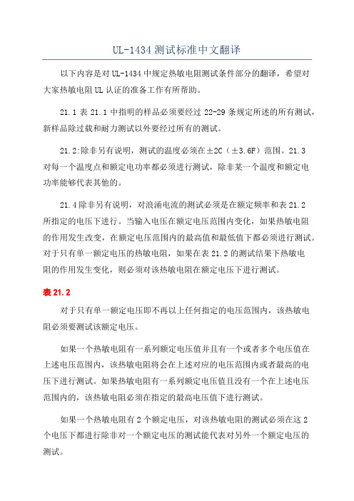
UL-1434测试标准中文翻译以下内容是对UL-1434中规定热敏电阻测试条件部分的翻译,希望对大家热敏电阻UL认证的准备工作有所帮助。
21.1表21.1中指明的样品必须要经过22-29条规定所述的所有测试,新样品除过载和耐力测试以外要经过所有的测试。
21.2:除非另有说明,测试的温度必须在±2C(±3.6F)范围。
21.3对每一个温度点和额定电功率都必须进行测试,除非某一个温度和额定电功率能够代表其他的。
21.4除非另有说明,对浪涌电流的测试必须是在额定频率和表21.2所指定的电压下进行。
当输入电压在额定电压范围内变化,如果热敏电阻的作用发生改变,在额定电压范围内的最高值和最低值下都必须进行测试。
对于只有单一额定电压的热敏电阻,如果在表21.2的测试结果下热敏电阻的作用发生变化,则必须对该热敏电阻在额定电压下进行测试。
表21.2对于只有单一额定电压即不再以上任何指定的电压范围内,该热敏电阻必须要测试该额定电压。
如果一个热敏电阻有一系列额定电压值并且有一个或者多个电压值在上述电压范围内,该热敏电阻将会在上述对应的电压范围内或者最高的电压下进行测试。
如果热敏电阻有一系列额定电压值且没有一个在上述电压范围内的,该热敏电阻必须在指定的最高电压值下进行测试。
如果一个热敏电阻有2个额定电压,对该热敏电阻的测试必须在这2个电压下都进行除非对一个额定电压的测试能代表对另外一个额定电压的测试。
21.6所谓稳定的温度是指,连续三次成功测量读数/每隔10%/过去的持续时间/测试必须表明温度变化最大不超过±1.0C(±1.8F),在任何情况下,时间间隔必须少于5分钟。
22.校准测试22.1概述22.1.1在可接受条件下,每一个热敏电阻的样品都必须接受22.2描述的R/T测试和22.3、22.4条描述的可接受的校准测试。
所有测试结果必须在制造商所描述的极限范围内。
22.1.2以下测试是对之前23、24,26-28校准测试的重复进行,测试结果必须在表22.1或者22.2所指明的其中一个等级内,或者在规定的成品标准限制范围内,并且:A)一个浪涌电流抑制器与其对应的可接受的R/T曲线的不同点不能超过表22.1所指明的。
ASTM B43-98(2004)无缝红铜管尺寸

Designation:B 43–98(Reapproved 2004)Standard Specification forSeamless Red Brass Pipe,Standard Sizes 1This standard is issued under the fixed designation B 43;the number immediately following the designation indicates the year of original adoption or,in the case of revision,the year of last revision.A number in parentheses indicates the year of last reapproval.A superscript epsilon (e )indicates an editorial change since the last revision or reapproval.This standard has been approved for use by agencies of the Department of Defense.1.Scope*1.1This specification 2covers seamless red brass (Copper Alloy UNS No.C23000)3pipe in all nominal pipe sizes,both regular and extra-strong.In the annealed temper (O61),the pipe is suitable for use in plumbing,boiler feed lines,and for similar purposes.In the drawn general purpose temper (H58),the pipe is suitable for architectural applications,such as guard railings and stair hand railings.1.2The values stated in inch-pound units are to be regarded as the standard.The values given in parentheses are provided for information purposes only.1.3The following hazard caveat pertains only to the test method portion,Section 9,of this specification.This standard does not purport to address all of the safety concerns,if any,associated with its use.It is the responsibility of the user of this standard to establish appropriate safety and health practices and determine the applicability of regulatory limitations prior to use.1.4Warning —Mercury is a definite health hazard in use and disposal.(See 9.1.)2.Referenced Documents2.1The following documents of the issue in effect on date of material purchase form a part of this specification to the extent referenced herein:2.2ASTM Standards:4B 153Test Method for Expansion (Pin Test)of Copper and Copper-Alloy Pipe and TubingB 154Test Method for Mercurous Nitrate Test for Copper and Copper AlloysB 601Classification for Temper Designations for Copper and Copper Alloys—Wrought and CastE 8Test Methods of Tension Testing of Metallic Materials E 29Practice for Using Significant Digits in Test Data to Determine Conformance with SpecificationsE 53Test Methods for Determination of Copper in Unal-loyed Coppers by GravimetryE 62Test Methods for Chemical Analysis of Copper and Copper Alloys (Photometric Methods)E 112Test Methods for Determining Average Grain Size E 243Practice for Electromagnetic (Eddy Current)Exami-nation of Copper and Copper Alloy TubesE 255Practice for Sampling Copper and Copper Alloys for the Determination of Chemical CompositionE 478Test Methods for Chemical Analysis of Copper AlloysE 527Practice for Numbering Metals and Alloys (UNS)3.Terminology 3.1Definitions:3.1.1tube,seamless —a tube produced with a continuous periphery in all stages of the operations.3.1.1.1pipe —a seamless tube conforming to the particular dimensions commercially known as nominal or standard pipe sizes.3.1.2lengths —straight pieces of the product.3.1.2.1standard —uniform lengths recommended in a Sim-plified Practice Recommendation or established as a Commer-cial Standard.3.2Definition of Term Specific to This Standard:3.2.1capable of —as used in this specification,the test need not be performed by the producer of the material.However,should subsequent testing by the purchaser establish that the material does not meet these requirements the material shall be subject to rejection.4.Ordering Information4.1Orders for material under this specification shall include the following information:4.1.1Temper (see 6.1),4.1.2Pipe size,regular or extra-strong (see 11.2),4.1.3Length (see 11.3),4.1.4Total length of each size,and1This specification is under the jurisdiction of ASTM Committee B05on Copper and Copper Alloys and is the direct responsibility of Subcommittee B05.04on Pipe and Tube.Current edition approved May 1,2004.Published May 2004.Originally approved in st previous edition approved in 1998as B 43–98e 1.2For ASME Boiler and Pressure Vessel Code applications see related Specifi-cation SB-43in Section II of that Code.3The system for copper and copper alloys (see Practice E 527)is a simple expansion of the former standard designation system accomplished by the addition of a prefix “C”and a suffix “00.”The suffix can be used to accommodate composition variations of the base alloy.4For referenced ASTM standards,visit the ASTM website,,or contact ASTM Customer Service at service@.For Annual Book of ASTM Standards volume information,refer to the standard’s Document Summary page on the ASTM website.1*A Summary of Changes section appears at the end of this standard.Copyright ©ASTM International,100Barr Harbor Drive,PO Box C700,West Conshohocken,PA 19428-2959,United States.4.1.5If material is required to meet ASME Boiler and Pressure Vessel Code (see 6.1,6.2,or 6.3),4.1.6Certification,if required (see 20.1),4.1.7Mill test report,if required (see 21.1),4.1.8Hydrostatic test,if required,and 4.1.9Pneumatic test,if required.4.1.10Mercurous Nitrate Test,if required (Section 9).5.Chemical Composition5.1The material shall conform to the following chemical requirements:Copper,%84.0to 86.0Lead,max,%0.05Iron,max,%0.05Zincremainder5.2These specification limits do not preclude the presence of other elements.Limits for unnamed elements are to be established by agreement between manufacturer or supplier and purchaser.5.2.1For copper alloys in which zinc is specified as the remainder,either copper or zinc shall be permitted to be taken as the difference between the sum of all the elements analyzed and 100%.5.2.1.1When all the elements in the table in 5.1are analyzed,their sum shall be 99.8%minimum.6.Temper6.1All pipe shall normally be furnished in the O61(an-nealed)(see Classificiation B 601)condition.6.2In the O61(annealed)temper,the degree of annealing shall be sufficient to produce complete recrystallization with an average grain size not in excess of 0.050mm.The surface of the test specimen for grain size determination shall approxi-mate a radial longitudinal section and shall be prepared and examined in accordance with Test Methods E 112.6.3The pipe is permitted to be furnished in the H58(drawn general purpose)temper,if agreed upon between the manufac-turer and the purchaser.(See Table 1.)7.Mechanical Properties7.1Material in the O61(annealed)temper specified to meet the requirements of the ASME Boiler and Pressure Vessel Code only shall have tensile properties as prescribed in Table 1.7.2All H58(drawn general purpose)material shall have the tensile properties as prescribed in Table 1.8.Expansion Test8.1Specimens in the O61(annealed)temper shall withstand an expansion of 25%of the outside diameter when expandedin accordance with Test Method B 153.The expanded pipe shall show no cracking or rupture visible to the unaided eye.Pipe ordered in the drawn (H)condition is not subject to this test.N OTE 1—The term “unaided eye,”as used herein,permits the use of corrective spectacles necessary to obtain normal vision.8.2As an alternative to the expansion test for pipe over 4in.(102mm)in diameter in the O61(annealed)condition,a section 4in.in length shall be cut from the end of one of the lengths for a flattening test.This 4-in.specimen shall be flattened so that a gage set at three times the wall thickness will pass over the pipe freely throughout the flattened part.The pipe so tested shall develop no cracks or flaws visible to the unaided eye (see Note 1)as a result of this test.In making the flattening test the elements shall be slowly flattened by one stroke of the press.9.Mercurous Nitrate Test9.1Warning —Mercury is a definite health hazard and therefore equipment for the detection and removal of mercury vapor produced in volatilization is recommended.The use of rubber gloves in testing is advisable.9.2When the test is required to be performed,the test specimens,cut 6in.(152mm)in length,shall,after proper cleaning,withstand an immersion for 30min without cracking in the standard mercurous nitrate solution prescribed in Test Method B 154.Immediately after removal from the solution,the specimen shall be wiped free of excess mercury and examined for cracks.9.3Product of the O61(annealed)temper shall pass the mercurous nitrate test when tested in accordance with Test Method B 154.9.3.1The test need not be performed except when indicated in the contract or purchase order at the time of placing of the order.10.Nondestructive Testing10.1The material shall be tested in the final size but is permitted to be tested prior to the final anneal or heat treatment,when these thermal treatments are required,unless otherwise agreed upon by the manufacturer or supplier and purchaser.10.2Eddy-Current Test —Each piece of material from 1⁄8in.up to and including 21⁄2in.nominal outside diameter or within the capabilities of the eddy-current tester,shall be subjected to an eddy-current test.Testing shall follow the procedures of Practice E 243except for determination of “end effect.”The material shall be passed through an eddy-current testing unit adjusted to provide information on the suitability of the material for the intended application.10.2.1Notch-depth standards rounded to the nearest 0.001in.(0.025mm)shall be 10%of the nominal wall thickness.The notch depth tolerances shall be 60.0005in.(0.013mm).Alternatively,when a manufacturer uses speed insensitive equipment that allows the selection of a maximum imbalance signal,a maximum imbalance signal of 0.3%is permitted to be used.10.2.2Material that does not actuate the signaling device of the eddy-current test shall be considered as conforming to theTABLE 1Tensile RequirementsTemper Designation Tensile Strength,min.ksi (MPa)Yield Strength A min.ksi (MPa)Elongation in 2-in.min.%Standard Former O61Annealed40.0(276)12.0(83)35H58Drawn general purpose44.0(303)18.0(124)...AAt 0.5%extension underload.requirements of this test.Material with discontinuities indi-cated by the testing unit is permitted to be reexamined or retested,at the option of the manufacturer,to determine whether the discontinuity is cause for rejection.Signals that are found to have been caused by minor mechanical damage,soil or moisture shall not be cause for rejection of the material provided the dimensions of the material are still within prescribed limits and the material is suitable for its intended application.10.3Hydrostatic Test—When specified,the material shall stand,without showing evidence of leakage,an internal hydro-static pressure sufficient to subject the material to afiber stress of6000psi(41MPa),determined by the following equation for thin hollow cylinders under tension.The material need not be tested at a hydrostatic pressure of over1000psi(6.9MPa) unless so specified.P52St/~D20.8t!where:P=hydrostatic pressure,psi(or MPa),t=wall thickness of the material,in.(or mm),D=outside diameter of the material in.(or mm),andS=allowable stress of the material,psi(or MPa).10.3.1For material less than1⁄2in.(12.7mm)in outside diameter and less than0.060in.(1.5mm)in wall thickness,the test is permitted to be made at the option of the manufacturer by pneumatically testing to the requirements of10.4.10.4Pneumatic Test—When specified,the material shall be subjected to an internal air pressure of60psi(415kPa) minimum for5s without showing evidence of leakage.The test method used shall permit easy visual detection of any leakage, such as by having the material under water or by the pressure-differential method.Any evidence of leakage shall be cause for rejection.11.Dimensions and Permissible Variations11.1For the purpose of determining conformance with the dimensional requirements prescribed in this specification,any measured value outside the limiting values for any dimensions may be cause for rejection.11.2Standard Dimensions,Wall Thickness,and Diameter Tolerances—The standard dimensions,wall thickness,and diameter tolerances shall be in accordance with Table2. 11.3Length and Length Tolerances—The standard length of red brass pipe is12ft(3.66m)with a tolerance of61⁄2in.(13 mm).11.4Squareness of Cut—The departure from squareness of the end of any pipe shall not exceed the following:Outside Diameter,in.(mm)ToleranceUp to5⁄8(15.9),incl0.010in.(0.25mm)Over5⁄8(15.9)0.016in./in.(0.016mm/mm)of diameter11.5Roundness—The roundness tolerance for straight length tubes with a wall thickness to outside diameter ratio of 0.01to0.05(inclusive)shall be6%of the nominal outside diameter.For tubes with a wall thickness to outside diameter ratio over0.05,the roundness tolerance shall be3%of the nominal outside diameter.11.5.1The measurement for roundness shall be made from the outside diameter.The deviation from roundness is mea-sured as the difference between the major and minor diameters as determined at any one cross section of the tube.The major and minor diameters are the diameters of two concentric circles just enclosing the outside surface of the tube at the cross section.11.6Straightness Tolerance—For pipe of H58(drawn gen-eral purpose)temper of Nominal Pipe Sizes from1⁄4to12in. inclusive,the maximum curvature(depth of arc)shall not exceed1⁄2in.(13mm)in any10-ft(3048-mm)portion of the total length.For H58temper pipe of other sizes,and for the O61(annealed)temper,no numerical values are established, however,the straightness of the pipe shall be suitable for the intended application.12.Workmanship,Finish and Appearance12.1The material shall be free of defects of a nature that interfere with normal commercial applications.It shall be well cleaned and free of dirt.13.Sampling13.1Sampling—The lot size,portion size,and selection of sample pieces shall be as follows:13.1.1Lot Size—The lot size shall be as follows:Pipe Size,in.Lot Weight,lb(kg)Up to11⁄2,incl5000(2270)or fraction thereofOver11⁄2to4,incl10000(4550)or fraction thereofOver440000(18100)or fraction thereof 13.1.2Portion Size—Sample pieces shall be taken for test purposes from each lot according to the following schedule:Number of Piecesin LotNumber of Sample Piecesto be Taken AA1to50151to2002201to15003Over15000.2%of total number of piecesin the lot,but not to exceed10sample piecesA Each sample piece shall be taken from a separate tube.13.1.3Sampling for Visual and Dimensional Examination—Minimum sampling for visual and dimensional examination shall be as follows:Lot size(Pieces/lot)Sample size2to8Entire lot9to90891to15012151to28019281to50021501to1200271201to3200353201to1000003810001to35000046In all cases,the acceptance number is zero and the rejection number is one.Rejected lots are permitted to be screenedandresubmitted for visual and dimensional examination.All de-fective items shall be replaced with acceptable items prior to lot acceptance.14.Number of Tests and Retests14.1Chemical Analysis —Samples for chemical analysis shall be taken in accordance with Practice E 255.Drillings,millings,etc.,shall be taken in approximately equal weight from each of the sample pieces selected in accordance with 13.1.2and combined into one composite sample.The mini-mum weight of the composite sample that is to be divided into three equal parts shall be 150g.14.1.1Instead of sampling in accordance with Practice E 255,the manufacturer shall have the option of determining conformance to chemical composition as follows:Conform-ance shall be determined by the manufacturer by analyzing samples taken at the time the castings are poured or samples taken from the semi-finished product.If the manufacturer determines the chemical composition of the material during the course of manufacture,he shall not be required to sample and analyze the finished product.The number of samples taken for determination of chemical composition shall be as follows:14.1.1.1When samples are taken at the time the castings are poured,at least one sample shall be taken for each group of castings poured simultaneously from the same source of molten metal.14.1.1.2When samples are taken from the semi-finished product,a sample shall be taken to represent each 10000lbTABLE 2Standard Dimensions,Weights,and TolerancesN OTE —All tolerances are plus and minus except as otherwise indicated.Nominal or Standard Pipe Size,in.OutsideDiameter,in.(mm)Average Outside Diameter Tolerances,A in.(mm)AllMinusWallThickness,in.(mm)Tolerance,B in.(mm)Theoretical Weight,lb/ft (kg/m)Regular1⁄80.405(10.3)0.004(0.10)0.062(1.57)0.004(0.10)0.253(0.376)1⁄40.540(13.7)0.004(0.10)0.082(2.08)0.005(0.13)0.447(0.665)3⁄80.675(17.1)0.005(0.13)0.090(2.29)0.005(0.13)0.627(0.933)1⁄20.840(21.3)0.005(0.13)0.107(2.72)0.006(0.15)0.934(1.39)3⁄41.050(26.7)0.006(0.15)0.114(2.90)0.006(0.15) 1.27(1.89)11.315(33.4)0.006(0.15)0.126(3.20)0.007(0.18) 1.78(2.65)11⁄4 1.660(42.2)0.006(0.15)0.146(3.71)0.008(0.20) 2.63(3.91)11⁄2 1.900(48.3)0.006(0.15)0.150(3.81)0.008(0.20) 3.13(4.66)2 2.375(60.3)0.008(0.20)0.156(3.96)0.009(0.23) 4.12(6.13)21⁄2 2.875(73.0)0.008(0.20)0.187(4.75)0.010(0.25)5.99(8.91)3 3.500(88.9)0.010(0.25)0.219(5.56)0.012(0.30)8.56(12.7)31⁄2 4.000(102)0.010(0.25)0.250(6.35)0.013(0.33)11.2(16.7)4 4.500(114)0.012(0.30)0.250(6.35)0.014(0.36)12.7(18.9)5 5.562(141)0.014(0.36)0.250(6.35)0.014(0.36)15.8(23.5)6 6.625(168)0.016(0.41)0.250(6.35)0.014(0.36)19.0(28.3)88.625(219)0.020(0.51)0.312(7.92)0.022(0.56)30.9(46.0)1010.750(273)0.022(0.56)0.365(9.27)0.030(0.76)45.2(67.3)1212.750(324)0.024(0.61)0.375(9.52)0.030(0.76)55.3(82.3)Extra Strong1⁄80.405(10.3)0.004(0.10)0.100(2.54)0.006(0.15)0.363(0.540)1⁄40.540(13.7)0.004(0.10)0.123(3.12)0.007(0.18)0.611(0.909)3⁄80.675(17.1)0.005(0.13)0.127(3.23)0.007(0.18)0.829(1.23)1⁄20.840(21.3)0.005(0.13)0.149(3.78)0.008(0.20) 1.23(1.83)3⁄41.050(26.7)0.006(0.15)0.157(3.99)0.009(0.23) 1.67(2.48)11.315(33.4)0.006(0.15)0.182(4.62)0.010(0.25)2.46(3.66)11⁄4 1.660(42.2)0.006(0.15)0.194(4.93)0.010(0.25) 3.39(5.04)11⁄2 1.900(48.3)0.006(0.15)0.203(5.16)0.011(0.28) 4.10(6.10)2 2.375(60.3)0.008(0.20)0.221(5.61)0.012(0.30) 5.67(8.44)21⁄2 2.875(73.0)0.008(0.20)0.280(7.11)0.015(0.38)8.66(12.9)3 3.500(88.9)0.010(0.25)0.304(7.72)0.016(0.41)11.6(17.3)31⁄2 4.000(102)0.010(0.25)0.321(8.15)0.017(0.43)14.1(21.0)4 4.500(114)0.012(0.30)0.341(8.66)0.018(0.46)16.9(25.1)5 5.562(141)0.014(0.36)0.375(9.52)0.019(0.48)23.2(34.5)6 6.625(168)0.016(0.41)0.437(11.1)0.027(0.69)32.2(47.9)88.625(219)0.020(0.51)0.500(12.7)0.035(0.89)48.4(72.0)1010.750(273)0.022(0.56)0.500(12.7)0.040(1.0)61.1(90.9)A The average outside diameter of a tube is the average of the maximum and minimum outside diameters as determined at any one cross section of the pipe.BMaximum deviation at any onepoint.(4550kg)or fraction thereof,except that not more than one sample shall be required per piece.14.1.1.3Due to the discontinuous nature of the processing of castings into wrought products,it is not practical to identify specific casting analysis with a specific quantity offinished material.14.1.1.4In the event that heat identification or traceability is required,the purchaser shall specify the details desired. 14.2Retests:14.2.1If any test specimen shows defective machining or developsflaws,it shall be discarded and another specimen substituted.14.2.2If the results of the test on one of the specimens fail to meet the specified requirements,two additional specimens shall be taken from different sample pieces and tested.The results of the tests on both of these specimens shall meet the specified requirements.Failure of more than one specimen to meet the specified requirements for a particular property shall be cause for rejection of the entire lot.14.2.3If the chemical analysis fails to conform to the specified limits,analysis shall be made on a new composite sample prepared from additional pieces selected in accordance with13.1.The results of this retest shall comply with the specified requirements.15.Test Methods15.1The properties enumerated in this specification shall,in case of disagreement,be determined in accordance with the following applicable methods:Test ASTM Designation(Section2) Chemical analysis E53,E62,E478Tension E8Expansion(pin test)B153Mercurous nitrate B15415.2Tension test specimens shall be of the full section of the pipe and shall conform to the requirements of the section, Specimens for Pipe and Tube,of Test Methods E8,unless the limitations of the testing machine preclude the use of such a specimen.Test specimens conforming to Type No.1of Fig.13, Tension Test Specimens for Large-Diameter Tubular Products, of Test Methods E8is permitted to be used when a full section specimen cannot be tested.15.3Whenever tension test results are obtained from both full size and from machined test specimens and they differ,the results obtained from full size test specimens shall be used to determine conformance to the specification requirements. 15.4Tension test results on material covered by this speci-fication are not seriously affected by variations in speed of testing.A considerable range of testing speed is permissible; however,it is recommended that the rate of stressing to the yield strength not exceed100ksi(690MPa)/min.Above the yield strength it is recommended that the movement per minute of the testing machine head under load not exceed0.5in./in.(0.5mm/mm)of gage length(or distance between grips for full-section specimens).16.Significance of Numerical Limits16.1For purposes of determining compliance with the specified limits for requirements of the properties listed in the following table,an observed value or a calculated value shall be rounded as indicated in accordance with the rounding method of Practice E29.Property Rounded Unit forObserved or Calculated Value Chemical composition nearest unit in the last right-handplace offigures of the specifiedlimitTensile StrengthYield Strengthnearest ksi(nearest5MPa)17.Inspection17.1The manufacturer shall afford the inspector represent-ing the purchaser,all reasonable facilities,without charge,to satisfy him that the material is being furnished in accordance with the specified requirements.18.Rejection and Rehearing18.1Material that fails to conform to the requirements of this specification shall be subject to rejection.Rejection is to be reported to the manufacturer or supplier promptly and in writing.In case of dissatisfaction with the results of the test,the manufacturer or supplier shall have the option to make claim for a rehearing.19.Packaging and Package Marking19.1The material shall be separated by size,composition, and temper,and prepared for shipment in such a manner as to ensure acceptance by common carrier for transportation and to afford protection from the normal hazards of transportation.19.2Each shipping unit shall be legibly marked with the purchase order number,metal or alloy designation,temper, size,total length or piece count or both,and name of supplier. The specification number shall be shown,when specified. 20.Certification20.1When specified on the purchase order the manufacturer shall furnish to the purchaser a certificate stating that each lot has been sampled,tested,and inspected in accordance with this specification and has met the requirements.When material is specified to meet the requirements of ASME Boiler and Pressure Vessel Code,the certification requirements are man-datory.l Test Report21.1When specified on the purchase order,the manufac-turer shall furnish to the purchaser a test report showing results of tests required by the specification.22.Keywords22.1copper alloy UNS No.C23000;red brasspipeSUPPLEMENTARY REQUIREMENTSThe following supplementary requirements shall apply only when specified by the purchaser in the inquiry,contract,or order,for agencies of the U.S.Ggovernment.S1.Referenced DocumentsS1.1The following documents of the issue in effect on date of material purchase form a part of this specification to the extent referenced herein:S1.1.1Federal Standards:5Fed.Std.No.102Preservation,Packaging and Packing LevelsFed.Std.No.123Marking for Shipment (Civil Agencies)Fed.Std.No.185Identification Marking of Copper and Copper-Base Alloy Mill Products S1.1.2Military Standard:5MIL-STD-129Marking for Shipment and Storage S1.1.3Military Specification:5MIL-C-3993Packaging of Copper and Copper-Base Alloy Mill ProductsS2.Quality AssuranceS2.1Responsibility for Inspection:S2.1.1Unless otherwise specified in the contract or pur-chase order,the manufacturer is responsible for the perfor-mance of all inspection and test requirements specified.Except as otherwise specified in the contract or purchase order,the manufacturer shall use his own or any other suitable facilities for the performance of the inspection and test requirementsunless disapproved by the purchaser at the time the order is placed.The purchaser shall have the right to perform any of the inspections or tests set forth when such inspections and tests are deemed necessary to assure that the material conforms to prescribed requirements.S3.Identification MarkingS3.1All material shall be properly marked for identification in accordance with Fed.Std.No.185except that the ASTM specification number and the alloy number shall be used.S4.Preparation for DeliveryS4.1Preservation,Packaging,Packing:S4.1.1Military Agencies —The material shall be separated by size,composition,grade,or class and shall be preserved and packaged,Level A or C,and packed,Level A,B,or C,as specified in the contract or purchase order,in accordance with the requirements of MIL-C-3993.S4.1.2Civil Agencies —The requirements of Fed.Std.No.102shall be referenced for definitions of the various levels of packaging protection.S4.2Marking:S4.2.1Military Agencies —In addition to any special mark-ing required by the contract or purchase order,marking for shipment shall be in accordance with MIL-STD-129.S4.2.2Civil Agencies —In addition to any special marking required by the contract or purchase order,marking for shipment shall be in accordance with Fed.Std.No.123.APPENDIX(Nonmandatory Information)X1.METRIC EQUIV ALENTSX1.1The SI unit for strength properties now shown is in accordance with the International System of Units (SI).The derived SI unit for force is the newton (N),which is defined as that force which when applied to a body having a mass of one kilogram gives it an acceleration of one metre per second squared (N =kg·m/s 2).The derived SI unit for pressure orstress is the newton per square metre (N/m 2),which has been named the pascal (Pa)by the General Conference on Weights and Measures.Since 1ksi =6894757Pa the metric equiva-lents are expressed as megapascal (MPa),which is the same as MN/m 2and N/mm 2.5Available from Standardization Documents Order Desk,Bldg.4,Section D,700Robbins Ave.,Philadelphia,PA 19111-5094,ATTN:NPODS.SUMMARY OF CHANGESCommittee B05has identified the location of selected changes to this standard since the last issue B43–96 that may impact the use of this standard.(1)The minimum tensile strength requirement of the H58 temper(see Table1)was changed to become44.0ksi(303 MPa).The previous value was40.0ksi.(2)Section11.6,Straightness Tolerance,was added to include straightness requirements.ASTM International takes no position respecting the validity of any patent rights asserted in connection with any item mentioned in this ers of this standard are expressly advised that determination of the validity of any such patent rights,and the risk of infringement of such rights,are entirely their own responsibility.This standard is subject to revision at any time by the responsible technical committee and must be reviewed everyfive years and if not revised,either reapproved or withdrawn.Your comments are invited either for revision of this standard or for additional standards and should be addressed to ASTM International Headquarters.Your comments will receive careful consideration at a meeting of the responsible technical committee,which you may attend.If you feel that your comments have not received a fair hearing you should make your views known to the ASTM Committee on Standards,at the address shown below.This standard is copyrighted by ASTM International,100Barr Harbor Drive,PO Box C700,West Conshohocken,PA19428-2959, United States.Individual reprints(single or multiple copies)of this standard may be obtained by contacting ASTM at the above address or at610-832-9585(phone),610-832-9555(fax),or service@(e-mail);or through the ASTM website().。