SNC313中文资料
313轴承尺寸参数
313轴承尺寸参数引言313轴承是一种常见的机械零件,广泛应用于各种旋转设备中。
为了确保轴承能够正常运转,我们需要了解313轴承的尺寸参数。
本文将对313轴承的尺寸参数进行全面、详细、完整且深入地探讨。
313轴承的基本结构313轴承由内外圈、滚动体和保持架组成。
其中,内圈和外圈的直径决定了轴承的尺寸大小,滚动体的直径决定了轴承的承载能力,保持架则起到固定滚动体的作用。
313轴承的主要尺寸参数313轴承的尺寸参数包括内圈直径、外圈直径、滚动体直径和保持架尺寸等。
内圈直径内圈直径是指313轴承内圈的直径。
内圈直径的大小直接影响着轴承的安装和使用。
内圈直径通常以毫米(mm)为单位进行表示。
外圈直径外圈直径是指313轴承外圈的直径。
外圈直径的大小决定了轴承在外部设备中的安装空间。
外圈直径通常以毫米(mm)为单位进行表示。
滚动体直径滚动体直径是指313轴承滚动体的直径。
滚动体直径的大小与轴承的承载能力有直接关系。
滚动体直径通常以毫米(mm)为单位进行表示。
保持架尺寸保持架尺寸包括保持架的宽度和长度。
保持架的尺寸大小会影响轴承的稳定性和使用寿命。
保持架尺寸通常以毫米(mm)为单位进行表示。
313轴承尺寸参数的选择在选择313轴承尺寸参数时,需要考虑以下几个因素:轴承负荷轴承的尺寸参数应能够承受所施加的负荷。
负荷包括径向负荷和轴向负荷,轴承的尺寸参数应能够满足负荷的需求。
轴承速度轴承的尺寸参数还应能够适应所需的转速。
根据轴承的尺寸和材料,轴承的行程可以适应不同的转速。
轴承的可用空间轴承的尺寸参数应能够适应安装空间的限制。
在选择轴承时,要确保轴承的尺寸与设备的空间要求相匹配。
轴承的使用寿命轴承的尺寸参数还要符合设备的使用寿命要求。
过小的尺寸可能导致轴承寿命过短,过大的尺寸可能导致设备结构的不稳定。
313轴承尺寸参数的标识方法313轴承的尺寸参数通常以数字或字母的形式进行标识。
常见的标识方法包括:1.内圈直径以字母“d”表示,外圈直径以字母“D”表示,滚动体直径以字母“B”表示,保持架尺寸以字母“C”表示。
CSNE151中文资料
CSNE151中⽂资料Representative photograph, actual product appearance may vary.Due to regional agency approval requirements, some products may not be available in your area. Please contact your regional Honeywell office regarding your product of choice. CSNE151CSN Series closed loop current sensor, measures AC, DC or impulse current, 25 amp-turns nominal, ± 36 amp-turns range, smaller housing, 1000 turnFeaturesCurrent sensing up to 1200 ampsMeasures ac, dc and impulse currentsCompetitive cost/performance ratioRapid responseHigh overload capabilityHigh level of electrical isolation between primary and secondary circuitsIndustrial operating temperature rangeSmall size and weightTypical ApplicationsVariable speed drivesOvercurrent protectionGround fault detectorsCurrent feedback control systemsRoboticsUPS and telecommunication power suppliesWelding power suppliesAutomotive - Battery management systemsWattmetersDescriptionThe CSN Series of closed loop current sensors are based on the principles of the Magnetoresistive or Hall effects, and the null balance or zero magnetic flux method (feedback system). The magnetic flux in the sensor core is constantly controlled at zero. The amount of current required to balance zero flux is the measure of the primary current flowing through the conductor, multiplied by the ratio of the primary to secondary windings. This closed loop current is the output from the device and presents an image of the primary current reduced by thenumber of secondary turns at any time. This current can be expressed as a voltage by passing it through a resistor.CSNE151CSN Series closed loop current sensor, measures AC, DC or impulse current, 25 amp-turns nominal, ± 36 amp-turns range, smaller housing, 1000 turnProduct SpecificationsSensor Type Closed Loop LinearSensed Current Type ac or dcSensed Current Range± 36 APackage Style Series Connect PCB MountOutput Type CurrentMaximum Continuous Current± 36 ASupply Current± 10 mA + outputSupply Voltage± 15.0 VdcOffset Current< ± 0.15 mAOffset Current Drift< ± 0.6 mACoil Resistance @ 70 °C110 OhmResponse Time< 1 µsCoil Turns1000Output Nominal25 mAOperating Temperature Range0 °C to 70 °C [32 °F to 158 °F]Storage Temperature Range-40 °C to 90 °C [-40 °F to 194 °F]Minimum Measuring Resistance100 OhmMaximum Measuring Resistance320 OhmHousing Material Glass-filled PBT (UL94-V0)Mounting PCB on 13 pinsPinout Style 5 pinAccuracy± 0.5 %Availability GlobalComment Standard 25 A sensor with 5 integral primary turns. UNSPSC Code411121UNSPSC Commodity411121 TransducersSeries Name CSN SeriesCSNE151CSN Series closed loop current sensor, measures AC, DC or impulse current, 25 amp-turns nominal, ± 36 amp-turns range, smaller housing, 1000 turnCSNE151CSN Series closed loop current sensor, measures AC, DC or impulse current, 25 amp-turns nominal, ± 36 amp-turns range, smaller housing, 1000 turn PERSONAL INJURYDO NOT USE these products as safety or emergency stop devices, or in any other application where failure of the product could result in personal injury.Failure to comply with these instructions could result in death or serious injury.MISUSE OF DOCUMENTATIONThe information presented in this product sheet (or catalog) is for reference only.DO NOT USE this document as product installation information.Complete installation, operation and maintenance information is provided in the instructions supplied with each product. Failure to comply with these instructions could result in death or serious injury.Copyright Honeywell Inc.1998-2006 All rights reserved.。
卡特挖机313D参数资料

发动机
每公升/加仑油耗可产出最大的工作量
采用 ACERT™ 技术的 Cat® C4.2 发动机优化了性能并符合美国 EPA Tier 3 和欧 IIIA 排放标准。通过先进的空气和燃油系统 技术以及集成式电子系统,ACERT 技术能在燃烧期间降低排放。Cat C4.2 发动机功率超强,可提供更大液压压力,从而提 升生产率,并降低移动每吨物料的成本。 发动机自动控制和燃油输送 二级控制装置和单触式命令可最大限度地提高燃油效率,降低噪声等级。燃油输送由 ADEM™ A4 发动机控制器管理,以便 从使用的每公升(每加仑)燃油获得最佳性能。灵活的燃油匹配,让发动机可以快速响应不同作业需求。 曲轴和活塞 锻制的整体式感应淬火曲轴增强平衡、减少振动并提高耐磨性。耐热的铝合金活塞具有较短的压缩高度,效率更高、寿命 更长。 省油模式 省油模式作为标准功能提供,让您可以平衡性能需求和燃油经济性,同时使挖掘力和提升能力保持确的控制装置提供高效性能
出色性能 313D 液压系统专为高效率和高性能设计。辅助液压装置和电 气管路已布置到动臂座架,使液压回路的安装更轻松。紧凑 设计利用更短的管线,减少了摩擦和压降,因此能够更高效 地使用动力。 • 动臂油缸杆端和斗杆油缸两端的液压缓冲器,可吸收冲击、
降低噪声并延长油缸使用寿命。 • 当控制装置位于空档时,流量减至最低,以降低油耗和延
重载斗杆 2.5 m 重载斗杆配备有更多板件、新锻造零件和焊接接头, 提高了耐用性、挖掘力和提升能力。
动臂 4.65 m 整体式重载动臂配备有由新锻造件制成的零件,以 及更多更厚的板件。左侧安装有照明灯,改善了黑暗和 弱光条件下的可见性。
多功能性
更多选件,执行更多工作
Cat 铲斗和 Cat 掘地工具(GET,(Ground Engaging Tools, 掘地工具))经过设计并与机器配套使用,确保了最佳性 能,且将油耗控制到最低。它们按照 Caterpillar 规格制造, 在任何应用场合均可保证高质量和耐用性。 一般负荷型铲斗 一般负荷型铲斗专为用于挖掘冲击力小的中等研磨性物料 (如泥土、肥土、石砾和粘土)的机器而设计。 超重负荷型铲斗 超重负荷型铲斗最适合碎石和花岗岩之类研磨性极高的应用 场合。
星科技SDOCKU313 USB 3.1(10Gbps)SATA硬盘连接器说明书

Quick start guideDE: Bedienungsanleitung - FR: Guide de l'utilisateur - ES: Guía del usuario - IT: Guida per l'uso - NL: Gebruiksaanwijzing - PT: Guia do usuário - Manual Revision: 04/15/2015Packaging contents• 1 x USB 3.1 dock for SATA drives • 1 x USB 3.1 A-to-B cable • 1 x universal adapter • 3 x power adapter plug (NA/UK/EU/AUS)•1 x instruction manualSystem requirements• USB-enabled computer system with an available USB port • 2.5 in. or 3.5 in. SATA HDD or SSDNote: To obtain the maximum USB throughput, recommends that you use a PC with a USB 3.1 Gen 2 port.Operating systems are subject to change. For the latest requirements, please visit /SDOCKU313.SDOCKU313USB 3.1 (10 Gbps) dock for SATA drivesProduct overviewFront viewPower buttonPower and activity LED Drive slot Drive eject Rear viewUSB 3.1 type-B DC power connector Install the drive Warning! Hard drives and storage enclosures should be handled carefully, especially when they’re transported. If you’re not careful with your hard disk, you may lose data as a result. Always handle storage devices with caution.1. Connect the external power adapter from the drive dock to a power outlet.2. Insert a 2.5 in. or 3.5 in. drive into the drive slot on the top of the docking station. Make sure that the connectors on the drive are facing the same corner of the slot that has a cutout in the door. The label on the drive should face the front of the dock.3. Connect the included USB 3.1 cable from the drive dock to an available USB port on your computer system. Your computer can be turned on or turned off when you connect the USB cable.4. Press the Power button on the top of the drive dock. The LED under the power button should light up to indicate that the dock is powered on. The LED blinks when the drive is being accessed.Prepare the drive If you install a hard drive or solid-state drive that already has data on it, after you plug in the drive, it appears under My Computer or Computer with a drive letter assigned to it.If you install a brand-new drive that doesn’t contain any data, you must prepare the drive for use.If you use a computer that’s running Windows® 2000, Windows® XP , Windows Vista®, or Windows® 7, do the following:1. Depending on the OS version that you’re running, do one of the following:• On your desktop, right-click My Computer .• On your desktop, right-click Computer .2. Click Manage .3. On the Computer Management screen, click Disk Management .4. Locate the disk that is labeled Unallocated . To confirm that the drive is the correct one, check the drive capacity.5. Right-click the section of the window that says Unallocated and click New Partition .6. To set up the drive, complete the instructions in the New Partition wizard.When the drive is successfully installed, the disk appears under My Computer or Computerwith a drive letter assigned to it.FCC Compliance Statement This equipment has been tested and found to comply with the limits for a Class A digital device, pursuant to Part 15 of the FCC rules. These limits are designed to provide reasonable protection against harmful interference when the equipment is operated in a commercial environment. This equipment generates, uses and can radiate radio frequency energy and, if not installed and used in accordance with the instruction manual, may cause harmful interference to radio communications. Operation of this equipment in a residential area is likely to cause harmful interference in which case the user will be required to correct the interference at his own expense. This device complies with part 15 of the FCC Rules. Operation is subject to the following two conditions: (1) This device may not cause harmful interference, and (2) this device must accept any interference received, including interference that may cause undesired operation. Changes or modifications not expressly approved by could void the user’s authority to operate the equipment.Industry Canada Statement This Class A digital apparatus complies with Canadian ICES-003. Cet appareil numérique de la classe [A] est conforme à la norme NMB-003 du Canada.CAN ICES-3 (A)/NMB-3(A)Use of Trademarks, Registered Trademarks, and other Protected Names and Symbols This manual may make reference to trademarks, registered trademarks, and other protected names and/or symbols of third-party companies not related in any way to . Where they occur these references are for illustrative purposes only and do not represent an endorsement of a product or service by , or an endorsement of the product(s) to which this manual applies by the third-party company in question. Regardless of any direct acknowledgement elsewhere in the body of this document, hereby acknowledges that all trademarks, registered trademarks, service marks, and other protected names and/or symbols contained in this manual and related documents are the property of their respective holders.Technical Support ’s lifetime technical support is an integral part of our commitment to provide industry-leading solutions. If you ever need help with your product, visit /support and access our comprehensive selection of online tools, documentation, and downloads. For the latest drivers/software, please visit /downloadsWarranty Information This product is backed by a two-year warranty. warrants its products against defects in materials and workmanship for the periods noted, following the initial date of purchase. During this period, the products may be returned for repair, or replacement with equivalent products at our discretion. The warranty covers parts and labor costs only. does not warrant its products from defects or damages arising from misuse, abuse, alteration, or normal wear and tear.Limitation of Liability In no event shall the liability of Ltd. and USA LLP (or their officers, directors, employees or agents) for any damages (whether direct or indirect, special, punitive, incidental, consequential, or otherwise), loss of profits, loss of business, or any pecuniary loss, arising out of or related to the use of the product exceed the actual price paid for the product. Some states do not allow the exclusion or limitation of incidental or consequential damages. If such laws apply, the limitations or exclusions contained in this statement may not apply to you.About driver installationNo driver or software installation is required for this product because the hard drive dock is natively supported and the drivers are already installed.Remove the driveNote: Make sure that the drive isn’t being accessed by the computer before you proceed.1. To remove the disk drive from the operating system, do one of the following:• On computers running a version of Windows, click Safely Remove Device .• On computers running a version of Mac OS, drag the drive to the trash can icon.For more information, see the documentation that came with your operating system.2. Press the Power button on the top of the dock and wait for the dock to finish powering down.3. To release the disk drive, press the Drive eject button on the top of the dock.4. Pull the disk drive from the drive slot on the top of the docking station.。
【研发】NS313(N06601)镍铬钴钼合金
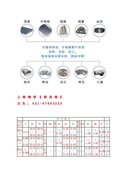
余 量
- --
0.15 0.15
0.30 0.50 ≤ ≤
~ ~ --- ~ ~ 0.03 0.03
0.45 0.60
0.70 1.50 0 0
NS13 ≤ 1 0.05
19.0 ~ 21.0
NS14 ≤ 1 0.030
25.0 ~ 27.0
NS14 ≤ 2 0.05
19.5 ~ 23.5
NS33 ≤ 5 0.015
NS313 预热:
工件在加热之前和加热过程中都必须进行表面清理,保持表面清洁。若加热环境含有硫、 磷、铅或其他低熔点金属,NS313 合金将变脆。杂质来源于做标记的油漆、粉笔、润滑 油、水、燃料等。燃料的硫含量要低,如液化气和天然气的杂质含量要低于 0.1%,城市 煤气的硫含量要低于 0.25g/m3,石油气的硫含量低于 0.5%是理想的。
760℃高温材料变形高温合金 变形高温合金是指可以进行热、冷变形加工,工作温度范围-253~1320℃,具有良 好的力学性能和综合的强、韧性指标,具有较高的抗氧化、抗腐蚀性能的一类合金。按 其热处理工艺可分为固溶强化型合金和时效强化型合金。GH 后位数字表示分类号即 1、 固溶强化型铁基合金 2、时效硬化型铁基合金 3、固溶强化型镍基合金 4、钴基合金 GH 后,二,三,四位数字表示顺序号。
2、时效强化型合金
使用温度为-253~950℃,一般用于制作航空、航天发动机的涡与叶片等结构件。 制作涡的合金工作温度为-253~700℃,要求具有良好的高低温强度和抗疲劳性能。例 如:GH4169 合金,在 650℃的高屈服强度达 1000MPa;制作叶片的合金温度可达 950℃, 例如:GH220 合金,950℃的拉伸强度为 490MPa,940℃、200MPa 的持久寿命大于 40 小 时。
SIMATIC S7-300 CPU 313C 产品说明书
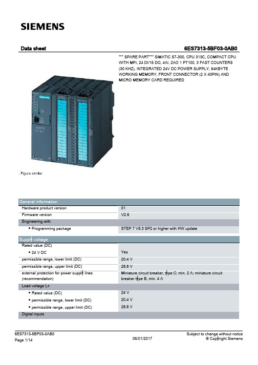
128 byte 128 byte
124.0 to 126.7 124.0 to 125.7 752 to 761 752 to 755
1 016 1 016 1 008 1 008
253 253 250 250
3
none 4
8 8 6
4 8; In rack 3 max. 7
Yes Yes 6 wk; At 40 °C ambient temperature 10 s
IEC timer ● present ● Type ● Number
Data areas and their retentivity retentive data area in total Flag ● Number, max. ● Retentivity available ● Retentivity preset ● Number of clock memories Data blocks ● Number, max. ● Size, max. ● Retentivity adjustable ● Retentivity preset Local data ● per priority class, max.
Hardware configuration Number of expansion units, max. Number of DP masters ● integrated ● via CP Number of operable FMs and CPs (recommended) ● FM ● CP, PtP ● CP, LAN Rack ● Racks, max. ● Modules per rack, max.
Nesting depth ● per priority class ● additional within an error OB
MAX313中文资料

Note 1: Signals on NC_, NO_, COM_, or IN_ exceeding V+ or V- will be clamped by internal diodes. Limit forward diode current to maximum current rating.
元器件交易网
MAX312/MAX313/MAX314
10Ω, Quad, SPST, CMOS Analog Switches
ABSOLUTE MAXIMUM RATINGS
Voltages Referenced to GND V+ ...........................................................................-0.3V to +44V V- ............................................................................+0.3V to -44V V+ to V-...................................................................-0.3V to +44V VL .....................................................(GND - 0.3V) to (V+ + 0.3V) All Other Pins (Note 1) ................................(V- - 2V) to (V+ + 2V)
Range (2Ω max) o Guaranteed ESD Protection > 2000V per Method
C3中文说明书
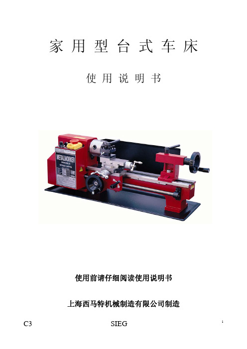
C3
SIEG
3
操作前: 1. 当机床停止使用或在电源插座插入插座之前,开关务必处在“关”的位置; 2. 切勿尝试使用不适当的辅助机构并进行超负荷运行,优良的配件可以从总
经销处购买; 3. 为顺利的进行操作,在机床使用前对设备和零件都要认真的进行检查,是
否存在零件使用已超过期限和存在损坏情况; 4. 对已受损的零件应请专业维修人员进行更换或修理; 5. 对已失去功能的开关应及时更换。
8.尾座顶尖
17.溜板箱
9.尾座体
18.床鞍进给手柄
19.丝杆 20.电动机电刷盖 21.乱扣盘表(选购件) 22.挂轮罩壳 23.无级变速控制旋钮 24.倒顺开关 25.急停开关 26.高低速操作手柄 27.丝杆倒顺转操作手柄
C3
SIEG
5
1. 床头箱 机床主轴的传动是通过电动机的同步带轮皮带与主轴同步带轮传动的,主 轴的无级变速是由#23 操作手柄进行调节的,在电器面板上可以找到转速 的范围。 #3 卡盘防护罩(是特殊选购的附件主要是学校教学时选装的)作用是防止 学生将卡盘钥匙遗忘在卡盘上,同时启动机床导致钥匙飞出来的安全防 护。 三爪卡盘(4)是安装在主轴法兰上,拆卸卡盘只要松开主轴法兰后面的 3 只紧固螺母,便可将卡盘从三个螺钉孔处拆卸。 随机附件中的三只反爪是为了扩大夹紧容量用的。主轴法兰上有六个孔, 是用来安装诸如四爪卡盘和花盘等(见特殊附件的介绍)。
除; (2) 不合适的保险丝不能用; (3) 需要拆卸或更换保险丝,要确保正确更换(包括认定标记和电线的颜
色); (4) 更换保险丝盖,要求从经销商处购买;
C3
SIEG
9
2. 车床安装 车床要安装在较重和强度较好的工作台上,要有足够的高度。这样对于操
国家仪器SCXI终端块说明书
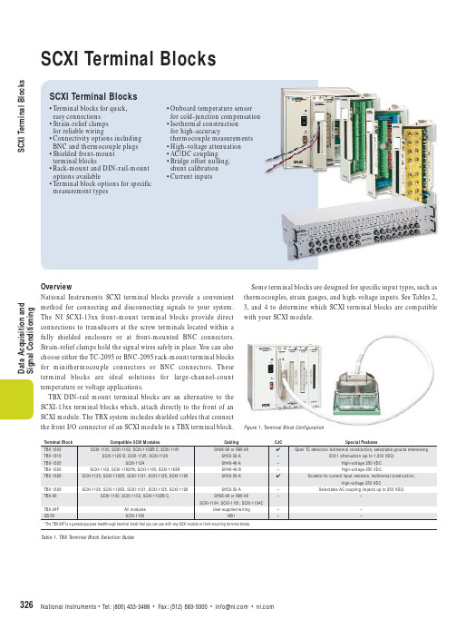
D a t a A c q u i s i t i o n a n d S i g n a l C o n d i t i o n i n gOverviewNational Instruments SCXI terminal blocks provide a convenient method for connecting and disconnecting signals to your system.The NI SCXI-13xx front-mount terminal blocks provide direct Some terminal blocks are designed for specific input types,such as thermocouples,strain gauges,and high-voltage inputs.See Tables 2,3,and 4 to determine which SCXI terminal blocks are compatible with your SCXI module.S C X I T e r m i n a l B l o c k sSCXI Terminal BlocksSCXI Terminal Blocks•Terminal blocks for quick,easy connections •Strain-relief clamps for reliable wiring•Connectivity options including BNC and thermocouple plugs •Shielded front-mount terminal blocks•Rack-mount and DIN-rail-mount options available•Terminal block options for specific measurement types•Onboard temperature sensor for cold-junction compensation •Isothermal construction for high-accuracythermocouple measurements •High-voltage attenuation •AC/DC coupling •Bridge offset nulling,shunt calibration •Current inputsFigure 1. Terminal Block ConfigurationSCXI Terminal BlocksSCXI Terminal BlocksData Acquisition and Signal ConditioningTBX Terminal BlockSelection GuideUse the following steps to select the correct combination of TBX terminal blocks and cables for your SCXI system:1. Select the required terminal blocks –For each SCXI module,use Table 1 to select the proper TBX terminal block.If a TBX-13xx terminal block is not available for your SCXI module,select the appropriate number of general-purpose TBX-24F feedthrough terminal blocks.2. Select cabling – For each TBX terminal block,Table 1 lists the cable needed to connect the TBX terminal block to the SCXI module.Shielded cables are available in lengths of 1,2,and 5 m.If using the TBX-1303,you also have the option to build a custom cable using the SBS-96F backshell kit.For each TBX-1303 for which you will build a custom cable,select two SBS-96F kits.If using the TBX-24F,you will use discrete wires to connect the TBX-24F to an SCXI front-mounting terminal block.Therefore,select the appropriate SCXI front-mounting terminal block for each SCXI module that will use the TBX-24F.3. Rack-mount accessory (optional)– Ifmounting for 19 in.rack enclosures is needed,use Table 2to select the appropriate number of TBX-RM1rack-mount kits.4. Calibration – Calibration of cold-junction sensors and attenuation terminal blocks is available for some devices.For moreinformation,please visit /calibrationTable 2. Rack-Mount Widths of TBX Terminal BlocksS C X I T e r m i n a l B l o c k sD a t a A c q u i s i t i o n a n d S i g n a l C o n d i t i o n i n gSCXI-1300......................................................................................................777687-00The SCXI-1300 connects input signals to the SCXI-1100,SCXI-1102/B/C,and SCXI-1104/C modules.The SCXI-1300 is a general-purpose terminal block with an onboard temperature sensor for cold-junction compensation.Also works with SCXI-1181 and SCXI-1181K modules.SCXI-1301......................................................................................................777687-0120-screw terminal block for the SCXI-1140,SCXI-1181,and SCXI-1181K modules.SCXI-1302......................................................................................................777687-0250-screw terminal block for SCXI-1180 feedthrough panel.SCXI-1303(See Figure 1)..............................................................................777687-03Terminal block for use with the SCXI-1100 and SCXI-1102/B/C modules.Designed especially for high-accuracy thermocouple measurements,the SCXI-1303 includes isothermal construction that minimizes errors caused by thermal gradients between terminals and the cold-junction sensor.The SCXI-1303 also includes circuitry for open-thermocouple detection as well as automatic ground referencing for floating (nongrounded) thermocouples.SCXI-1304......................................................................................................777687-04The SCXI-1304,for the SCXI-114x modules,includes AC coupling circuitry,with switches on each channel.Each channel also includes a switchable connection to ground through a 100 k bias resistor to provide a reference for floating input sources.SCXI-1305 (See Figure 2)................................................................................777687-05Includes convenient BNC connectors for use with the SCXI-1120/D,SCXI-1121,SCXI-1125,SCXI-1126,and SCXI-114x.Functionally equivalent to the SCXI-1304terminal block,the SCXI-1305 includes switchable AC coupling circuitry and ground referencing on each channel.SCXI-1308......................................................................................................777687-08Current input terminal block for the SCXI-1100 and SCXI-1102/B/C analog input modules.Each input includes a 249 precision resistor so you can read 0 to 20 mA and 4 to 20 mA current inputs.SCXI-1310(See Figure 3)..............................................................................777687-10Connector and shell assembly used to create custom cabling solutions from the SCXI-1100,SCXI-1102/B/C,SCXI-1104/C,SCXI-114x,and SCXI-1181 to custom terminations.A low-cost alternative to SCXI terminal blocks,it consists of a hardened plastic enclosure and one connector with solder pins for signal connections.SCXI-1313......................................................................................................777687-13Extends the input range of the SCXI-1125 to 300 V rms or 300 VDC,on a per-channel basis programmatically through software commands.The SCXI-1313 also includes an onboard temperature sensor for thermocouples cold-junction compensation.SCXI Terminal BlocksFigure 3. SCXI-1310 Connector and Shell AssemblyFigure 2. SCXI-1305 Terminal BlockFigure 1. SCXI-1303 Terminal BlockSCXI Terminal BlocksSCXI-1314......................................................................................................777687-14 Front-mounting terminal block for the SCXI-1520 module.With factory-installed and socketed 350 quarter-bridge completion resistors for each channel.Eight 120 resistors for use with 120 quarter-bridge strain gauges are included,but not installed.It also includes two factory-installed,socketed 100 k shunt calibration resistors per channel.SCXI-1315......................................................................................................777687-15 8-channel front-mounting terminal block for the SCXI-1540 LVDT with six terminals for each LVDT channel – CH+,CH-,EX+,EX-,Synch,and GND.SCXI-1320 (See Figure 4)..............................................................................777687-20 General-purpose terminal block for connecting signals to the SCXI-1120/D, SCXI-1121,SCXI-1125,and SCXI-1126 modules.It includes an onboard temperature sensor for cold-junction compensation using thermocouples,but the SCXI-1328 is recommended for precision thermocouple measurements.SCXI-1321(See Figure 5)..............................................................................777687-21 Adds nulling and shunt calibration to SCXI-1121 strain guage applications.With a front-panel trimming potentiometer,you can manually null out the offset voltage of bridge transducers.Each channel includes shunt calibration circuits.When activated, a switch connects a 301 k shunt resistor in parallel with the strain gauge.Both the nulling resistor and the shunt resistor are socketed for easy customization.SCXI-1322......................................................................................................777687-22 Terminal block required to connect signals to the SCXI-1122 module that includes an onboard temperature sensor for cold-junction compensation.SCXI-1324......................................................................................................777687-24 High-voltage terminal block with 48 screw terminals for the SCXI-1160 relay module.SCXI-1325......................................................................................................777687-25 26-screw terminal block for the SCXI-1124 module.SCXI-1326......................................................................................................777687-26 High-voltage terminal block with 48 screw terminals for the SCXI-1162 Series and SCXI-1163 Series modules.SCXI-1327(See Figure 6)..............................................................................777687-27 With the SCXI-1327 you can extend the input range of the SCXI-1120/D and SCXI-1121 to ±250 V,and extend the threshold level of the SCXI-1126 module from 5 V up to 300 V.The extended input voltage range is enabled or disabled on a per-channel basis using switches located within the SCXI-1327.The SCXI-1327 also includes an onboard temperature sensor for cold-junction compensation with thermocouples. Using the SCXI-1327 reduces the input impedence of your SCXI module to 1 M.SCXI-1328(See Figure 7)..............................................................................777687-28 Isothermal terminal block with a high-precision cold-junction sensor for high-accuracy thermocouple applications with the SCXI-1120/D,SCXI-1121,or SCXI-1125.SCXI-1330......................................................................................................777687-30SCXITerminal BlocksData Acquisition andSignal ConditioningFigure 7. SCXI-1328 Terminal BlockFigure 6. SCXI-1327 Terminal BlockFigure 5. SCXI-1321 Terminal BlockFigure 4. SCXI-1320 Terminal BlockS C X I T e r m i n a l B l o c k sD a t a A c q u i s i t i o n a n d S i g n a l C o n d i t i o n i n gConnector and shell assembly (hardened plastic enclosure and solder pins) used to create custom cabling solutions from the SCXI-1120/D,SCXI-1121,SCXI-1125,SCXI-1126,and SCXI-1181 to custom terminations.SCXI-1331(See Figure 8)..............................................................................777687-31General-purpose terminal block for the SCXI-1127 multiplexer/matrix module with 64 generic screw terminals and a cold-junction compensation sensor.For SCXI-1127multiplexer applications or matrix configurations other than a multiple of eight columns by four rows.Includes sockets for matrix expansion cables.SCXI-1332(See Figure 9)..............................................................................777687-32Multiplexer/matrix terminal block for the SCXI-1127 configures the SCXI-1127 as an eight column by four row switching matrix.Y ou can connect signals to both the columns and rows using screw terminals.SCXI-1333......................................................................................................777687-33SCXI-1334......................................................................................................777687-34SCXI-1335......................................................................................................777687-35SCXI-1336......................................................................................................777687-36SCXI-1337......................................................................................................777687-37SCXI-1339......................................................................................................777687-39These terminal blocks are designed for use with the SCXI-1129 high-density matrix switching module.Each of these terminal blocks gives the high-density matrix a different configuration.See page 484 for more information on how to choose the appropriate series of terminal blocks for the SCXI-1129.SCXI-1338......................................................................................................777687-38Current input terminal block for the SCXI-1120/D,SCXI-1125,and SCXI-1126.Each input includes a 249 precision resistor for reading 0 to 20 mA or 4 to 20 mA current inputs.BNC-2095(See Figure 10)............................................................................777508-01The BNC-2095 has 32 labeled BNC connectors,one for each input channel of the SCXI-1100,or SCXI-1104/C.The BNC-2095 also includes circuitry for configurable signal referencing.Y ou can enable or disable both the pull-up and pull-down resistors on a per-channel basis using switches.TC-2095..........................................................................................................777509-01The TC-2095 has 32 miniature uncompensated thermocouple plugs,one for each input channel of the SCXI-1100 or SCXI-1102/B/C and a thermistor for accurate cold-junction compensation.In addition,the TC-2095 includes circuitry for configurable signal referencing.You can enable or disable both the pull-up and pull-down resistors on a per-channel basis using switches located on the rear of the TC-2095.The TC-2095 is not recommended for use with the SCXI-1104/C.The TC-2095 requires the SH96-96 or R96-96 for connection to a SCXI module.SCXI Terminal BlocksFigure 10. BNC-2095Figure 9. SCXI-1332 Terminal BlockFigure 8. SCXI-1331Terminal BlockSCXI TBX Terminal BlocksTBX-1303(See Figure 11)..............................................................................777207-03 Designed for thermocouples,with cold-junction compensation sensor,isothermal construction with a plastic cover to minimize thermal gradients,open-thermocouple detection circuitry,and automatic ground-referencing circuitry.With the SCXI-1102B/C, the TBX-1303 provides a high-impedance path to ground so that systems work reliably with either floating or ground-referenced thermocouples.For applications with the SCXI-1100,you can configure the channels as ground-referenced or floating in blocks of eight channels.The TBX-1303 also works with the SCXI-1181 breadboard module.TBX-96............................................................................................................777264-01 Mass termination terminal block that provides a generic solution for the SCXI-1100, SCXI-1102B/C,SCXI-1104/C,and the SCXI-1140 Series.TBX-1316(See Figure 12)..............................................................................777207-16 High-voltage terminal block,for extending the input range of the SCXI-1120/D, SCXI-1125,or SCXI-1126 modules to ±1000 VDC (680 V rms) Each input channel includes a 200:1 attenuation circuit,and offers a positive,negative,and ground terminal for up to 12 AWG wire.You can panel mount this enclosure or simply place it on a desktop.The hinged lid makes accessing the signals easier and key locked for safety.The TBX-1316 is rated for Category III installations.TBX-1325........................................................................................................777207-25 T erminal block with 30 screw terminals for signal connections to the SCXI-1124 module. You cable the TBX-1325 to the SCXI-1124 with the SH48-48-A shielded cable.TBX-1326(See Figure 13)..............................................................................777207-26 High-voltage terminal block with 48 screw terminals for signal connections to the SCXI-1162,SCXI-1162HV,SCXI-1163,and SCXI-1163R modules.You can cable the TBX-1326 to the SCXI module with the SH48-48-B shielded cable.Warning:The TBX-1326 and SH48-48-B limit the maximum working common-mode voltage between banks or between banks and earth ground to 250 V rms maximum.TBX-1328(See Figure 14)..............................................................................777207-28 T erminal block for the SCXI-1120/D,SCXI-1121,SCXI-1125,and SCXI-1126 modules. The TBX-1328 includes a total of24 screw terminals,including three terminals (CH+, CH-,and chassis ground) for each input channel and sockets for the installation of resistors for 4 to 20 mA inputs.When used with thermocouples,the TBX-1328 maximizes measurement accuracy with an isothermal construction and a plastic cover that minimizes thermal gradients across the terminal block and the resulting errors.TBX-1329(See Figure 15)..............................................................................777207-29 Provides selectable AC coupling for the SCXI-1120/D,SCXI-1121,SCXI-1125,and SCXI-1126 modules.TBX-24F..........................................................................................................777276-01 The TBX-24F is a general-purpose screw terminal block with feedthrough connections for 24 signal lines.You connect the TBX-24F to the SCXI module with discrete wires connected to a standard SCXI terminal block.SCXITerminal BlocksData Acquisition andSignal ConditioningFigure 14. TBX-1328Figure 13. TBX-1326Figure 12. TBX-1316Figure 11. TBX-1303Figure 15. TBX-1329Typical for 25 ˚C unless otherwise noted.SCXI-13xxCold-Junction SensorAccuracy and repeatability 1Sensor output for SCXI-1300,SCXI-1320, SCXI-1321...............................±10 mV/˚CSCXI-1303/1322/1327/1328...................... 1.91 V (at 0 ˚C) to 0.58 V (at 55 ˚C) (thermistor)Maximum field wire gauge for SCXI-1300/1302/1303/1314/1322/1324.....................26-16 AWG1301/1304/1313/1315/1320/1321/1325/1327/1328/1331/1332.....................26-14 AWGAC coupling (SCXI-1304 and SCXI-1305).........The AC coupling circuitry on each channel has a corner frequency of 0.16 Hz, rejection capacity of ±50 VDC, and input impedance of 2 M differential,1 Mcommon mode.Corner frequency.......................................0.16 Hz 1-pole RC DC rejection capacity................................±50 VDC Current input SCXI-1308/1338..................0 to 20 mABNC-2095, TC-2095Input connectorsBNC-2095...................................................32 BNC connectorsTC-2095......................................................32 thermocouple plugs, uncompensated Output (to SCXI module)...................................96-pin DINCold-junction sensor (TC-2095)Output........................................................ 1.91 V (0 ˚C) to 0.58 V (55 ˚C)Accuracy (15 to 35 ˚C)3.............................0.5 ˚C for SCXI-1102/B/C 0.65 ˚C for SCXI-1100Repeatability (15 to 35 ˚C)3.......................0.35 ˚C for SCXI 1102/B/C0.5 ˚C for SCXI-1100Signal referencingCH+ input...................................................10 M to +5 V, user switchableCH- input....................................................10 M or +10 to ground, user switchable 1-pole RCPhysicalDimensions.......................................................49.3 by 4.3 by 18.8 cm(19.0 by 1.7 by 7.4 in.)TBX SeriesTypical for 25˚ C unless otherwise noted.Maximum working voltage (signal + common mode)TBX-1316...................................................1000 VDC, 680 V rms TBX-1325...................................................250 V rms TBX-1326/1328/1329/24F.........................300 V rms Signal referencing on TBX-1303CH+ input...................................................10 M to +5 V (socketed)CH- input....................................................10 M or 10 to ground(user configurable, socketed)Input inpedance for TBX-1316Differential.................................................40 M Single-Ended..............................................20 M Absolute accuracy for TBX-1316Gain error...................................................1%Temperature drift.......................................20 ppm/˚CAC Coupling (TBX-1329 only)Corner frequency.......................................0.072 Hz 1-pole RC DC rejection capacity................................250 VDC Wire resistance of cables................................0.21 /m per conductorCold-Junction Sensor (TBX-1303 and TBX-1328)Accuracy and repeatability 4Sensor output................................................... 1.91 V (at 0 ˚C) to 0.58 V (at 55 ˚C) (thermistor)GeneralPhysicalCompatible DIN rails 5......................................DIN EN 50 022, DIN EN 50 035Screw terminal sizeTBX-1316...................................................26-12 AWG Others........................................................26-14 AWGDimensionsTBX-13036.........................................................19.7 by 11.2 by 7.62 cm(7.8 by 4.4 by 3.0 in.)TBX-1316..........................................................30 by 20 by 8.1 cm(11.8 by 7.9 by 3.2 in.)TBX-1325/1326/1328/13296............................12.7 by 11.2 by 7.62 cm(5.0 by 4.4 by 3.0 in.)TBX-24F............................................................12.4 by 4.3 by 5.1 cm(4.9 by 1.7 by 2.0 in.)TBX-96............................................................19.8 by 12.6 by 6.3 cm(7.8 by 4.9 by 2.5 in.)Certification and ComplianceSCXI-1320/1321/1326/1327/1328/1338.........300 V, Cat II working voltage SCXI-1322/1324/1325......................................250 V, Cat II working voltage TBX-1316..........................................................1000 V, Cat III working voltage TBX-1328/1329.................................................300 V, Cat II working voltage TBX-1325/1326.................................................250 V, Cat II working voltageEuropean ComplianceEMC ................................................................EN 61326 Group I Class A, 10 m,Table 1 ImmunitySafety ..............................................................EN 61010-1North American ComplianceEMC ................................................................FCC Part 15 Class A using CISPR Safety (SCXI-1320/1321/1326/1327/1328/1338/SCXI-1322/1324/1325) ...................UL Listed to UL 3111-1CAN/CSA C22.2 No. 1010.1Safety (TBX-1325/1326/1328/1329) ...............UL Listed to UL 3111-1CAN/CSA C22.2 No. 1010.1Australia and New Zealand ComplianceEMC (except TBX-1316)...................................AS/NZS 2064.1/2 (CISPR-11)1Accuracy and repeatability include combined effects of sensor, circuitry, and thermal gradientsbetween the sensor and any screw terminal. Thermal gradients for nonisothermal terminal blocks (SCXI-1300, SCXI-1320, SCXI-1321, SCXI-1322, and SCXI-1327) are assumed to be 0.4 ˚C.2With SCXI-1102 module. With SCXI-1100 module, add error of 0.15 ˚C3Accuracy and repeatability include combined effects of sensor, circuitry, and thermal gradients between the sensor and thermocouple connection.4Accuracy and repeatability include combined effects of sensor, circuitry, and thermal gradients between the sensor and any screw terminal.5TBX-1316 is not DIN-rail mountable6Height dimension (7.62 cm) includes DIN-rail mounting and plastic cover.For a definition of specific terms, please visit /glossaryS C X I T e r m i n a l B l o c k sD a t a A c q u i s i t i o n a n d S i g n a l C o n d i t i o n i n gSCXI-13xx, TBX, andBNC/TC Terminal Block SpecificationsSpecifications。
冷硫化粘接剂SK313
冷硫化粘接剂SK313中文名:冷硫化粘接剂SK313外文名:Vulcanizing cement形态:液体颜色:深灰色层气味:特殊气味成份:四氯乙烯产地:德国保质期:18个月型号:SK313规格:1kg/罐+40g/瓶施工量:每层300克/平方米一、产品主要用途及优点用途:冷硫化粘接剂SK313适用于橡胶与橡胶、橡胶与金属、橡胶与织物、织物与织物之间的粘接,它是皮带冷粘接、修补、滚筒包胶及各类橡胶衬垫材料应用的理想粘接剂。
优点:优质- 粘接强度通过了德国DIN工业标准,与热硫化粘接强度同级。
方便 - 简单的工具即可作业,不需借助硫化机等大型设备。
快捷 - 紧急抢修时,即修即用,使停机损失降至。
可靠 - 保质期为18个月,大大超出其它同类产品。
适用 - 操作的工作温度可至100℃,同时适合井上、井下工程。
二、技术参数固化:涂刷之后固化4小时,强度可达到原皮带70%,12小时达到100%。
20℃时密度:1.450±0.010g/cm³20℃时动态粘度:3500-4000mpas有机溶剂:84-87%总固体量:13-16%剥离强度(N/2.5cm): 固化2小时≥80,固化24小时≥140剪切强度(MPa): 固化20分钟≥2.0,固化24小时≥3.4难燃性:离火自熄三、操作时间冷硫化粘接剂SK313的操作间隔时间取决于工作环境的内部或外部温度或湿度。
在开始粘合前,可参照下面涂刷胶水的干燥时间:正常温度(10℃-30℃):35-30分钟高温(30℃或以上):25-20分钟粘接之前用手指背进行测试,若粘接剂稍微有粘性,则为最佳的粘接时间。
四、使用说明避免阳光直接照射,防止温度降低到0℃以下。
保证环境和物料温度+10℃到+45℃。
粘接表面:干燥洁净无化学物质和油脂等污物。
金属表面:用喷砂或打磨的方式将金属表面除锈且使其变得粗糙-推荐打磨深度为30um。
用德国进口输送带清洗剂SK353去除金属表面油污,粘接之前如果需要,涂刷一层金属底漆SK363并使其完全干燥,这样可以提高金属粘接面与橡胶的粘接力。
Cisco Nexus 3132Q、3132Q-X和3132Q-XL交换机产品介绍说明书
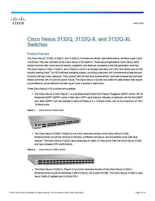
Data Sheet Cisco Nexus 3132Q, 3132Q-X, and 3132Q-XL SwitchesProduct OverviewThe Cisco Nexus® 3132Q, 3132Q-X, and 3132Q-XL Switches are dense, high-performance, 40-Gbps Layer 2 and 3 switches. They are members of the Cisco Nexus 3100 platform. These second-generation Cisco Nexus 3000 Series Switches offer improved port density, scalability, and features compared to the first-generation switches. The Cisco Nexus 3132Q, 3132Q-X, and 3132Q-XL come in a compact one-rack-unit (1RU) form factor and run the industry-leading Cisco® NX-OS Software operating system, providing customers with comprehensive features and functions that are widely deployed. They support both forward and reverse airflow (port-side exhaust and port-side intake) schemes with AC and DC power inputs. The Cisco Nexus 3132 are well suited for data centers that require a cost-effective, power-efficient line-rate Layer 2 and 3 access or leaf switch.Three Cisco Nexus 3132 switches are available:●The Cisco Nexus 3132Q (Figure 1) is a 40-Gbps Quad Small Form-Factor Pluggable (QSFP) switch with 32Enhanced QSFP (QSFP+) ports. It also has 4 SFP+ ports that are internally multiplexed with the first QSFP port. Each QSFP+ port can operate in native 40-Gbps or 4 x 10-Gbps mode, with up to a maximum of 104 x 10-Gbps ports.Figure 1. Cisco Nexus 3132Q Switch●The Cisco Nexus 3132Q-X (Figure 2) is a minor hardware revision of the Cisco Nexus 3132Q.Enhancements include the removal of retimers, a different port layout, and the addition of an LED laneselector. The Cisco Nexus 3132Q-X also consumes 40 watts (W) less power than the Cisco Nexus 3132Q and has increased CPU performance.Figure 2. Cisco Nexus 3132Q-X Switch●The Cisco Nexus 3132Q-XL (Figure 3) is a minor hardware revision of the Cisco Nexus 3132Q-X.Enhancements include an additional 4 GB of memory (for a total of 8 GB). The Cisco Nexus 3132Q-XL also has a 16GB of Logflash and 2.5-GHz CPU.Figure 3. Cisco Nexus 3132Q-XL SwitchMain BenefitsThe Cisco Nexus 3132Q, 3132Q-X, and 3132Q-XL provide the following main benefits:●Wire-rate Layer 2 and 3 switching on all ports1◦Layer 2 and 3 switching of up to 2.5 terabits per second (Tbps) and up to 1.4 billion packets per second (bpps) is provided in a compact 1RU form-factor switch.●High availability◦Virtual-port-channel (vPC) technology provides Layer 2 multipathing through the elimination of Spanning Tree Protocol and enables fully utilized bisectional bandwidth and simplified Layer 2 logical topologieswithout the need to change the existing management and deployment models.◦The 64-way equal-cost multipath (ECMP) routing enables the use of Layer 3 fat-tree designs and allows organizations to prevent network bottlenecks, increase resiliency, and add capacity with little networkdisruption.◦The switches offer fast reboot capabilities.◦Power-supply units (PSUs) and fans are hot swappable.●Flexibility◦The QSFP port can be configured to work as four 10-Gbps ports, offering deployment flexibility with maximum of 104 x 10-Gbps ports.●High performance◦Both switches deliver low nominal latency, which enables customers to implement high-performance infrastructure for high-frequency trading (HFT) workloads. Customers can also achieve faster application performance because of the serialization savings from switching at 40 Gigabit Ethernet speeds.●Purpose-built NX-OS operating system with comprehensive, proven innovations◦Power-on auto provisioning (POAP) enables touchless bootup and configuration of the switch, drastically reducing provisioning time.◦Cisco Embedded Event Manager (EEM) and Python scripting enable automation and remote operations in the data center.◦Advanced buffer monitoring reports real-time buffer utilization per port and per queue, which allows organizations to monitor traffic bursts and application traffic patterns.◦EtherAnalyzer is a built-in packet analyzer for monitoring and troubleshooting control-plane traffic and is based on the popular Wireshark open-source network protocol analyzer.◦Precision Time Protocol (PTP; IEEE 1588) provides accurate clock synchronization and improved data correlation with network packet capture and system events.1 Wire rate on all ports for packets greater than 200 bytes◦Complete Layer 3 unicast and multicast routing protocol suites are supported, including Border Gateway Protocol (BGP), Open Shortest Path First (OSPF), Enhanced Interior Gateway Routing Protocol (EIGRP), Routing Information Protocol Version 2 (RIPv2), Protocol-Independent Multicast sparse mode (PIM-SM), Source-Specific Multicast (SSM), and Multicast Source Discovery Protocol (MSDP).ConfigurationAll three switches have the following configuration:●32 fixed 40 Gigabit Ethernet QSFP+ ports● 4 SFP+ ports, which are multiplexed internally with the first QSFP+ port●Locator LED●Dual redundant power supplies●Redundant (3+1) fans●Support for forward (port-side exhaust) and reversed (port-side intake) airflow schemesThe Cisco Nexus 3132Q has the following configuration:●One 10/100/1000-Mbps management port located on the front of the chassis●One RS-232 serial console port located on the front of the chassis●One USB port located on the front of the chassisThe Cisco Nexus 3132Q-X has the following configuration:●Lane selector button and LED●One 10/100/1000-Mbps management port located on the rear of the chassis●One RS-232 serial console port on located on the rear of the chassis●One USB port located on the rear of the chassisThe Cisco Nexus 3132Q-XL has the following configuration:●8 GB of memory and 2.5-GHz CPU●Lane selector button and LED●One 10/100/1000-Mbps management port located on the rear of the chassis●One RS-232 serial console port located on the rear of the chassis●One USB port located on the rear of the chassisTransceiver and Cabling OptionsThe Cisco Nexus 3132Q, 3132Q-X, and 3132Q-XL have 32 QSFP+ ports. QSFP+ technology allows a smooth transition from 10 to 40 Gigabit Ethernet infrastructure in data centers. Each of the switches’ QSFP+ ports can operate in either native 40 Gigabit Ethernet mode or 4 x 10 Gigabit Ethernet mode. All switches support both fiber and copper cabling solutions for these two modes.For low-cost cabling, copper-based 40-Gbps Twinax cables can be used, and for longer cable reaches, short-reach optical transceivers are excellent. Connectivity can be established from the QSFP+ ports to 10 Gigabit Ethernet switches or hosts using a splitter cable that has a QSFP+ transceiver on one end and four SFP+ transceivers on the other end. Similar capability can be achieved on the fiber solution by using QSFP+ SR4 transceivers on both ends and procuring third-party fiber splitter MPO-to-LC cables.For details about the optics modules available and the minimum software release required for each supported optics module, visitFor more information about the transceiver types, see/en/US/products/hw/modules/ps5455/prod_module_series_home.html.Cisco NX-OS Software OverviewNX-OS is a data center–class operating system built with modularity, resiliency, and serviceability at its foundation. NX-OS helps ensure continuous availability and sets the standard for mission-critical data center environments. The self-healing and highly modular design of NX-OS makes zero-impact operations a reality and enables exceptional operation flexibility.Focused on the requirements of the data center, NX-OS provides a robust and comprehensive feature set that meets the networking requirements of present and future data centers. With an XML interface and a command-line interface (CLI) like that of Cisco IOS® Software, NX-OS provides state-of-the-art implementations of relevant networking standards as well as a variety of true data center–class Cisco innovations.Cisco NX-OS Software BenefitsTable 1 summarizes that benefits that NX-OS offers.Table 1. Benefits of Cisco NX-OS SoftwareCisco NX-OS Software Packages for the Cisco Nexus 3132Q, 3132Q-X, and 3132Q-XLThe software packages available for the Cisco Nexus 3132Q, 3132Q-X, and 3132Q-XL offer flexibility and a comprehensive feature set as well as consistency with Cisco Nexus access switches. The default system software has a comprehensive Layer 2 feature set with robust security and management features. To enable Layer 3 IP unicast and multicast routing functions, additional licenses need to be installed. Table 2 summarizes the software packages. See Table 4 later in this document for a complete list of software features.Table 2. Cisco NX-OS Software Packages Available for the Cisco Nexus 3132Q, 3132Q-X, and 3132Q-XLCisco Data Center Network ManagerThe Cisco Nexus 3132Q, 3132Q-X, and 3132Q-XL are supported in DCNM. DCNM is designed for hardware platforms enabled for NX-OS, which consist of the Cisco Nexus Family products. DCNM is a Cisco management solution that increases overall data center infrastructure uptime and reliability, hence improving business continuity. Focused on the management requirements of the data center network, DCNM provides a robust framework and comprehensive feature set that meets the routing, switching, and storage administration needs of present and future data centers. In particular, DCNM automates the provisioning process, proactively monitors the LAN by detecting performance degradation, secures the network, and simplifies the diagnosis of dysfunctional network elements.Product SpecificationsTable 3 lists the specifications for the Cisco Nexus 3132Q, 3132Q-X, and 3132Q-XL; Table 4 lists software features; and Table 5 lists management standards and support.Table 3. Specifications* Please refer to Cisco Nexus 3000 Series Verified Scalability Guide documentation for exact scalability numbers validated on for specific software releases:/en/US/products/ps11541/products_installation_and_configuration_guides_list.html.Table 4. Software Features●Jumbo frame support (up to 9216 bytes)●Advanced BGP features including BGP add-path for eBGP and iBGP, remove-private-as enhancements, andeBGP next-hop unchanged●IP-in-IP tunnel support●VXLANMulticast ●Multicast: PIMv2, PIM-SM, and PIM-SSM●Bootstrap router (BSR), Automatic Rendezvous Point (Auto-RP), and Static RP●MSDP and Anycast RP●Internet Group Management Protocol (IGMP) Versions 2 and 3Quality of service (QoS) ●Layer 2 IEEE 802.1p (class of service [CoS])●8 unicast and 8 multicast hardware queues per port●Per-port QoS configuration●CoS trust●Port-based CoS assignment●Modular QoS CLI (MQC) compliance●ACL-based QoS classification (Layers 2, 3, and 4)●MQC CoS marking●Differentiated services code point (DSCP) marking●Weighted Random Early Detection (WRED)●CoS-based egress queuing●Egress strict-priority queuing●Egress port-based scheduling: Weighted Round-Robin (WRR)●Explicit Congestion Notification (ECN)●Priority Flow Control (with 3 no-drop queues and 1 default queue with strict priority scheduling between queues●PBRSecurity ●Ingress ACLs (standard and extended) on Ethernet●Standard and extended Layer 3 to 4 ACLs: IPv4, Internet Control Message Protocol (ICMP), TCP, UserDatagram Protocol (UDP), etc.●VLAN-based ACLs (VACLs)●Port-based ACLs (PACLs)●Named ACLs●ACLs on virtual terminals (vtys)●DHCP snooping with Option 82●Port number in DHCP Option 82●DHCP relay●Dynamic Address Resolution Protocol (ARP) inspection●Configurable CoPP●Switched Port Analyzer (SPAN) with ACL filteringManagement ●Switch management using 10/100/1000-Mbps management or console ports●CLI-based console to provide detailed out-of-band management●In-band switch management●Locator and beacon LEDs●Port-based locator and beacon LEDs●Configurable CoPP●Configuration rollback●SSHv2●Telnet●AAA●AAA with RBAC●RADIUS●TACACS+●Syslog●Syslog generation on system resources (for example, FIB tables)●Embedded packet analyzer●SNMP v1, v2, and v3●Enhanced SNMP MIB supportTable 5. Management and Standards Support Description SpecificationMIB support Generic MIBs●SNMPv2-SMI●CISCO-SMI●SNMPv2-TM●SNMPv2-TC●IANA-ADDRESS-FAMILY-NUMBERS-MIB●IANAifType-MIB●IANAiprouteprotocol-MIB●HCNUM-TC●CISCO-TC●SNMPv2-MIB●SNMP-COMMUNITY-MIB●SNMP-FRAMEWORK-MIB●SNMP-NOTIFICATION-MIB●SNMP-TARGET-MIB●SNMP-USER-BASED-SM-MIB●SNMP-VIEW-BASED-ACM-MIB●CISCO-SNMP-VACM-EXT-MIB●CISCO-CLASS-BASED-QOS-MIBEthernet MIBs●CISCO-VLAN-MEMBERSHIP-MIB●LLDP-MIB●IP-MULTICAST-MIBConfiguration MIBs●ENTITY-MIB●IF-MIB●CISCO-ENTITY-EXT-MIB●CISCO-ENTITY-FRU-CONTROL-MIB●CISCO-ENTITY-SENSOR-MIB●CISCO-SYSTEM-MIB●CISCO-SYSTEM-EXT-MIB●CISCO-IP-IF-MIB Monitoring MIBs●NOTIFICATION-LOG-MIB●CISCO-SYSLOG-EXT-MIB●CISCO-PROCESS-MIB●RMON-MIB●CISCO-RMON-CONFIG-MIB●CISCO-HC-ALARM-MIBSecurity MIBs●CISCO-AAA-SERVER-MIB●CISCO-AAA-SERVER-EXT-MIB ●CISCO-COMMON-ROLES-MIB●CISCO-COMMON-MGMT-MIB●CISCO-SECURE-SHELL-MIB Miscellaneous MIBs●CISCO-LICENSE-MGR-MIB●CISCO-FEATURE-CONTROL-MIB ●CISCO-CDP-MIB●CISCO-RF-MIBLayer 3 and Routing MIBs●UDP-MIB●TCP-MIB●OSPF-MIB●BGP4-MIB●CISCO-HSRP-MIB●CISCO-IF-EXTENSION-MIB●CISCO-NTP-MIB●CISCO-IMAGE-MIB●CISCO-IMAGE-UPGRADE-MIBStandards ●IEEE 802.1D: Spanning Tree Protocol●IEEE 802.1p: CoS Prioritization●IEEE 802.1Q: VLAN Tagging●IEEE 802.1s: Multiple VLAN Instances of Spanning Tree Protocol●IEEE 802.1w: Rapid Reconfiguration of Spanning Tree Protocol●IEEE 802.3z: Gigabit Ethernet●IEEE 802.3ad: Link Aggregation Control Protocol (LACP)●IEEE 802.3ae: 10 Gigabit Ethernet●IEEE 802.1ab: LLDP●IEEE 1588-2008: Precision Time Protocol (Boundary Clock)RFC BGP●RFC 1997: BGP Communities Attribute●RFC 2385: Protection of BGP Sessions with the TCP MD5 Signature Option●RFC 2439: BGP Route Flap Damping●RFC 2519: Framework for Interdomain Route Aggregation●RFC 2545: Use of BGPv4 Multiprotocol Extensions●RFC 2858: Multiprotocol Extensions for BGPv4●RFC 3065: Autonomous System Confederations for BGP●RFC 3392: Capabilities Advertisement with BGPv4●RFC 4271: BGPv4●RFC 4273: BGPv4 MIB: Definitions of Managed Objects for BGPv4●RFC 4456: BGP Route Reflection●RFC 4486: Subcodes for BGP Cease Notification Message●RFC 4724: Graceful Restart Mechanism for BGP●RFC 4893: BGP Support for 4-Octet Autonomous System Number (ASN) Space●RFC 5549: BGP IPv4 Network Layer Reachability Information (NLRI) with IPv6 Next HopOSPF●RFC 2328: OSPF Version 2●8431RFC 3101: OSPF Not-So-Stubby-Area (NSSA) Option●RFC 3137: OSPF Stub Router Advertisement●RFC 3509: Alternative Implementations of OSPF Area Border Routers●RFC 3623: Graceful OSPF Restart●RFC 4750: OSPF Version 2 MIBRIP●RFC 1724: RIPv2 MIB Extension●RFC 2082: RIPv2 MD5 Authentication●RFC 2453: RIP Version 2●IP Services●RFC 768: User Datagram Protocol (UDP)●RFC 783: Trivial File Transfer Protocol (TFTP)●RFC 791: IP●RFC 792: ICMP●RFC 793: TCP●RFC 826: ARP●RFC 854: Telnet●RFC 959: FTP●RFC 1027: Proxy ARP●RFC 1305: Network Time Protocol (NTP) Version 3●RFC 1519: Classless Interdomain Routing (CIDR)●RFC 1542: BootP Relay●RFC 1591: Domain Name System (DNS) ClientSoftware RequirementsCisco Nexus 3100 platform switches are supported by Cisco NX-OS Software Release 6.0(2)U2(1) and later. Cisco Nexus 3100-XL series switches are supported by Cisco NX-OS software Release NXOS-703I2.2 and later. Cisco NX-OS interoperates with any networking OS, including Cisco IOS Software, that conforms to the networking standards mentioned in this data sheet.Regulatory Standards ComplianceTable 6 summarizes regulatory standards compliance for the Cisco Nexus 3100 platform.Table 6. Regulatory Standards Compliance: Safety and EMCOrdering InformationTable 7 provides ordering information for the Cisco Nexus 3132Q, 3132Q-X, and 3132Q-XL. Table 7. Ordering InformationService and SupportCisco offers a wide range of services to help accelerate your success in deploying and optimizing the Cisco Nexus 3100 platform in your data center. The innovative Cisco Services offerings are delivered through a unique combination of people, processes, tools, and partners and are focused on helping you increase operation efficiency and improve your data center network. Cisco Advanced Services uses an architecture-led approach to help you align your data center infrastructure with your business goals and achieve long-term value.Cisco SMARTnet™ Service helps you resolve mission-critical problems with direct access at any time to Cisco network experts and award-winning resources.With this service, you can take advantage of the Cisco Smart Call Home service capability, which offers proactive diagnostics and real-time alerts on your Cisco Nexus 3100 platform switches. Spanning the entire network lifecycle, Cisco Services help increase investment protection, optimize network operations, support migration operations, and strengthen your IT expertise.Cisco CapitalFinancing to Help You Achieve Your ObjectivesCisco Capital® can help you acquire the technology you need to achieve your objectives and stay competitive. We can help you reduce CapEx. Accelerate your growth. Optimize your investment dollars and ROI. Cisco Capital financing gives you flexibility in acquiring hardware, software, services, and complementary third-party equipment. And there’s just one predictable payment. Cisco Capital is available in more than 100 countries. Learn more.For More InformationFor more information, please visit /go/nexus3000.Printed in USA C78-729482-04 02/16。
GlobalSat TR-313 用户手册说明书

GlobalSat TR-313 User ManualTABLE OF CONTENTS1. Warning (3)2. Welcome (4)3. Introduction and Features (5)3.1 Introduction (5)3.2 LED Indicators (6)4. Device Operation (7)4.1 Device charging (7)4.2 SIM card Installation (8)4.3 Power (9)4.4 Emergency button (10)5. Contact Information (11)6. Safety Information (11)7. Limited Warranty (12)USE RESPONSIBLY. READ ALL INSTRUCTIONS ANDSAFETY INFORMATION BEFORE USE.Globalsat Worldcom Corporation / USGlobalsat, Inc., will not accept any responsibility whatsoever for accidents or violations of local Laws resulting from failure to observe common sense precautions and local laws. Your personal judgment, traffic regulations,and common sense must always take precedence over any directions produced by GPS receiver or the mapping software.Indemnification:User agrees to defend, indemnify and hold harmless GlobalSat WorldCom Corp. and USGlobalsat, Inc., its officers, directors, employees and agents against and from any third party claims, actions, damages or demands, including but not limited to, reasonable legal and accounting fees, resulting from user's use or misuse of this product, violation of these Terms, or any activities related to this product, or from user's violations of the rights of any other user of this product. Use of this Product is at user's own risk.Thank you for purchasing the GlobalSat TR-313. The TR-313 is a sleek, compact and feature rich Personal / Personnel tracking device. In addition to its telemetry abilities, the TR-313 unit incorporates a wide array of custom feature, functions and configurations for unique client requirements. TR-313 is a versatile device which can be used for many Personal & Personnel tracking applications. We appreciate your purchase of a GlobalSat Worldcom Product!3.1 IntroductionTR-313 is a 3G personal tracking device with fast GPS acquisition time. It is compact, portable and stylish in design capable to connect both GSM and GPRS wireless networks. Users can easily and remotely configure TR-313 and display GPS locations on remote monitoring / tracking platforms.3.2 LED IndicatorsPower Status LEDGSM LEDGPS LEDBluetooth LED (Optional function)Note: The TR313 BLE-enabled devices must be an authorized andpre-integrated TR-313 accessory in order to connect, not all BLE devices willconnect without pre-integration.4.1 Device charging1 2 3Using the device for the first time, rechargeable battery will require a complete 100% charge before TR-313 is operable. To maximize your device’s battery life, proceed by performing the steps listed below.1. Place the device on the charging cradle.2. Connect the Micro USB side of the cable to the cradle port and connect the otherend of the cable to the designated AC power source (USB/AC adaptor).3. Allow at least 6 hours of battery charging time.4.2 SIM Card Installation1 2 31. Unscrew the SIM card cover.2. Remove the cover.3. With the metal contacts facing down, with the notch of the SIM card positioned toyour lower left side as seen in the above #3 image, place the SIM card onto the SIM card compartment.4. Replace the back cover in its original compartment and re-screw the cover. Note: Before installing or taking out the SIM card, please power off the device.4.3 Power1. To turn the device “ON”, press and hold the power button for 1 second.2. To turn the device “OFF”, press and hold the power button for 3 seconds until thedevice vibrates.3. To perform a hard reset, press and hold the power button for 8 to 10 seconds.4. For developers accessing COM port connection from the device, press the powerbutton once quickly while the device is sitting on the cradle with the USB cable connected to PC.4.3 Emergency button1. While pressing and holding the emergency button, TR-313 will send the emergency SMS messages to pre-programmed phone numbers and continuously dial out to these phones numbers until one phone call is picked up. Call rotary.2. Once the emergency call is answered, the user and the contact may speak through the hands-free speakerphone.3. By default TR-313 allows the user to end a call by pushing the emergency button once.4. Users may also answer incoming phone calls by pushing the emergency button once when TR-313 exhibits ring tones.Note: .Please contact Technical Support for programming emergency phone numbers.GlobalSat WorldCom CorporationAddress: 16F., No.186, Jian 1st Rd., Jhonghe Dist., New Taipei City ,Taiwan TEL: +886-2-82263799 FAX: +886-2-82263899Please consult your airline prior to the operation of this product in the aircraft. . Operating this product in environments emitting intensive radio waves or radiation can affect the operation and functionality of this product.Avoid use in humid or rainy environment. Water ingress can disable or destroy this product beyond repair.Avoid using this product in a dusty environment. Dust ingress can compromise the products ability to function.Avoid situations that include Over-voltage, over charging, power cable damage may cause overheating or potential fire disaster.Never use any chemical or detergent to clean the Personal Tracker to prevent erosion of the surface or paintwork.In order to eliminate the risk of electric shock, make certain the charging cable is completely inserted / seated, do not touch the power cable plug / connectors with wet or damp hands.Do not charge the Device in any extreme cold or hot temperatures, which may cause damage to the device.Keep out of the reach of children during charging.Avoid direct prolonged exposure to sunlight and high temperatures to avoid the potential over-heating of the battery of this product, which may cause damage.Please do not attempt to repair this device yourself, contact Globalsat or USGlobalSat for Technical Support.Keep all the wires tidy in order to prevent damage or tangling.Globalsat/USGlobalsat (1) Year Limited WarrantyFOR CONSUMERS, WHO ARE COVERED BY CONSUMER PROTECTION LAWS OR REGULATIONS IN THEIR COUNTRY OF PURCHASE OR, IF DIFFERENT, IN THEIR COUNTRY OF RESIDENCE, THE BENEFITS CONFERRED BY THIS WARRANTY ARE IN ADDITION TO ALL RIGHTS AND REMEDIES CONVEYED BY SUCH CONSUMER PROTECTION LAWS AND REGULATIONS. THIS WARRANTY DOES NOT EXCLUDE, LIMIT OR SUSPEND ANY RITGHTS OF CONSUMERS ARISING OUT OF NONCONFORMITY WITH A SALES CONTRACT. SOME COUNTRIES, STATES AND PROVINCES DO NOT ALLOW THE EXCLUSION OR LIMITATION OF INCIDENTAL OR CONSEQUENTIAL DAMAGES OR ALLOW LIMITATIONS ON HOW LONG AN IMPLIED WARRANTY OR CONDITION MA Y LAST, SO THE LIMITATIONS OR EXCLUSIONS DESCRIBED BELOW MAY NOT APPLY TO YOU. THIS WARRANTY GIVES YOU SPECIFIC LEGAL RIGHTS, AND YOU MAY ALSO HAVE OTHER RIGHTS THAT VARY BY COUNTRY, STATE OR PROVIDENCE. THIS LIMITED WARRANTY IS GOVERNED BY AND CONSTRUED UNDER THE LAWS OF THE COUNTRY IN WHICH PRODUCT PURCHASE TOOK PLACE. GLOBALSAT/ USGLOBALSAT, THE WARRANTOR UNDER THIS LIMITED WARRANTY, IS IDENTIFIED AT THE END OF THIS DOCUMENT ACCORDING TO THE COUNTRY OR REGION IN WHICH THE PRODUCT PURCHASE TOOK PLACE.G lobalsat/ USGlobalsat’s warranty obligations for this hardware product are limited to the terms set forth below:Globalsat/ USGlobalsat, as defined below, warrants this hardware product against defects in materials product hardware against manufacturing defects in materials and workmanship under normal use for aperiod of ONE (1) year from the date of retail purchase by the original end-user purchaser and purchased from a recognized “authorized dealer”(“Warranty Period”).Products purchased from any unauthorized source, such as unauthorized e-Bay resellers, will not qualify for free warranty service/support and may require the end-user to pre-pay fees associated with, but not limited to the support, repair, replacement and shipping of the product to and from the service center. If a hardware defect arises and a valid claim is received by Globalsat/ USGlobalsat within the Warranty Period, at its option and to the extent permitted by law, Globalsat/ USGlobalsat will either (1) repair the product at no charge, using new parts or parts equivalent to new in performance and reliability, (2) exchange the product with a product that is new orequivalent to new in performance and reliability and is at least functionally equivalent to the original product or, (3) refund the purchase price of the product. Globalsat/ USGlobalsat may request that you replace defective parts with new or refurbished user-installable parts that Globalsat/ USGlobalsat provides in fulfillment of its warranty obligation. A replacement product or part, including a user-installable part that has been installed in accordance with instructions provided by Globalsat/ USGlobalsat, assumes the remaining warranty of the original product or ninety (90) days from the date of replacement or repair, whichever provides longer coverage for you. When a product or part is exchanged, any replacement item becomes your property and the replaced items becomes Globalsat/ USGlobalsat’s property. Parts provide by Globalsat/ USGlobalsat in fulfillment of its warranty obligation must be used in products for which warranty service is claimed. When a refund is given, the product for which the refund is provided must be returned to Globalsat/ USGlobalsat and becomes Globalsat/ USGlobalsat’s property.If a defect arises and a valid claim is received by Globalsat/ USGlobalsat after the first one hundred and eighty (180) days of Warranty period, a shipping and handling charge may apply to any repair or exchange of the product undertaken by Globalsat/ USGlobalsat.EXCLUSIONS AND LIMITATIONSThis Limited Warranty applies only to the hardware product manufactured by or for Globalsat that can be identified by the “Globalsat” trademark, trade name, or logo annexed to it. The Limited Warranty does not apply to any non-Globalsat hardware product or any software, even if packaged or sold with the Globalsat hardware.Manufacturers, suppliers, or publishers, other than Globalsat/ USGlobalsat, may provide their own warranties to the end user purchaser, but Globalsat/ USGlobalsat, in so far as permitted by law, provides their products “as-is”. Software distributed by Globalsat/ USGlobalsat with or without the Globalsat brand name (including, but not limited to system software) is not covered under this Limited Warranty. Refer to the licensing agreement accompanying the software for details of your rights with respect to its use. Globalsat/ USGlobalsat does not warrant that the operation of the product will be uninterrupted or error-free. Globalsat/USG lobalsat is not responsible for damage arising from failure to follow instructions relating to the product’s use.This warranty does not apply: (a) to consumable parts, such as batteries, unless damage has occurred due to a defect in materials and workmanship; (b) to cosmetic damage, including but notlimited to scratches, dents, and broken plastic on ports; (c) to damage cause by use accident, abuse, misuse, flood, fire, earthquake or other external causes; (e) to damage caused by operating the product outside the permitted or intended uses described by Globalsat/ USGlobalsat; (f) to damage caused by service (including upgrades and expansions) performed by anyone who is not a representative of Globalsat/ USGlobalsat or an Globalsat/ USGlobalsat authorized service provider;(g) to a product or part that has been modified to alter functionality or capability without the written permission of Globalsat/ USGlobalsat; or (h) if any Globalsat/ USGlobalsat serial number has been removed or defaced.IMPORTANT: Do not open the hardware product. Opening the hardware product may cause damage that is not covered by this warranty. Only Globalsat/ USGlobalsat or an authorized service provider should perform service on this hardware product.TO THE EXTENT PERMITTED BY LAW, THIS WARRANTY AND THE REMEDIES SET FORTH ABOVE ARE EXCLUSIVE AND IN LIEU OF ALL OTHER WARRANTIES, REMEDIES AND CONDITIONS, WHETHER ORAL OR WRITTEN, STATUTORY, EXPRESS OR IMPLIED. AS PERMITTED BY APPLICABLE LAW, GLOBALSAT/ USGLOBALSAT SPECIFICALLY DISCLAIMS ANY AND ALL STATUTORY OR IMPLIED WARRANTIES, INCLUDING, WITHOUT LIMITATION, WARRANTIES OF MERCHANTIBILITY AND FITNESS FOR A PARTICULAR PURPOSE AND WARRANTIES AGAINST HIDDEN OR LATENT DEFECTS. IF GLOBALSAT/ USGLOBALSAT CANNOT LAWFULLY DISCLAIM STATUTORY OR IMPLIED WARRANTIES THEN TO THE EXTENT PERMITTED BY LAW, ALL SUCH WARRANTIES SHALL BE LIMITED IN DURATION OF THE EXPRESS WARRANTY AND TO THE REPAIR OF REPLACEMENT SERVICE AS DETERMINED BY GLOBALSAT/ USGLOBALSAT IN ITS SOLE DISCRETION.No Globalsat/ USGlobalsat reseller, agent, or employee is authorized to make any modifications, extension, or addition to this warranty. If any term is held to be illegal or unenforceable, the legality or enforceability of the remaining terms shall not be affected or impaired.EXCEPT AS PROVIDED IN THIS WARRANTY AND TO THE MAXIMUM EXTENT PERMITTED BY LAW, GLOBALSAT/ USGLOBALSAT IS NOT RESPONSIBLE FOR DIRECT, SPECIAL, INCIDENTAL OR CONSEQUENTIAL DAMAGES RESULTING FROM ANY BREACH OF WARRANTY OR CONDITION, OR UNDER ANY OTHER LEGAL THEORY, INCLUDING BUT NOT LIMITED TO LOSS OF USE; LOSS OF REVENUE; LOSS OF ACTUAL OR ANTICIPATED PROFITS (INCLUDING LOSS OF PROFITS ON CONTRACTS); LOSS OF THE USE OF MONEY; LOSS OF ANTICIPATED SAVINGS; LOSS OF BUSINESS; LOSS OF OPPORTUNITY; LOSS OF GOODWILL; LOSS OF REPUTATION; LOSS OF;DAMAGE TO OR CORRUPTION OF DATA; OR ANY INDIRECT OR CONSEQUENTIAL LOSS OR DAMAGE HOWSOEVER CAUSED INCLUDING THE REPLACEMENT OF EQUIPMENT AND PROPERTY, ANY COSTS OF RECOVERING, PROGRAMMING OR REPRODUCING ANY PROGRAM OR DATA STORED IN OR USED WITH THE GLOBALSAT/ USGLOBALSAT PRODUCT AND ANY FAILURE TO MAINTAIN THE CONFIDENTIALITY OF DATA STORED ON THE PRODUCT. THE FOREGOING LIMITATION SHALL NOT APPLY TO DEATH OR PERSONAL INJURY CLAIMS, OR ANY STATUTORY LIABILITY FOR INTENTIONAL AND GROSS NEGLIGENT ACTS AND/OR OMISSIONS. GLOBALSAT/ USGLOBALSAT DISCLAIMS ANY RESPRESENTATION THAT IT WILL BE ABLE TO REPAIR ANY PRODUCT UNDER THIS WARRANTY OR MAKE A PRODUCT EXCHANGE WITHOUT RISK TO OR LOSS OF PROGRAMS OR DATA.OBTAINING WARRANTY SERVICEPlease access and review the online help resources referred to in the documentation accompanying this hardware product before seeking warranty service. If the product is still not functioning properly after making use of these resources, access the online website for instructions on how to obtain warranty service. You must follow Globalsat/ USGlobalsat warranty processes. Globalsat/ USGlobalsat may provide warranty service (i) by sending the unit to Globalsat/ USGlobalsat location, where service is performed at the location, or (ii) by sending the unit to an authorized Globalsat/ USGlobalsat supplier (iii) by sending you new or refurbished customer-installable replacement product or parts to enable you to service or exchange your own product (“RMA service”). Upon receipt of the replacement product or part, the original product or part becomes the property of Globalsat/ USGlobalsat and you agree to follow instructions, including, if requires, arranging the return of the product or part to Globalsat/ USGlobalsat in a timely manner. When providing RMA service requiring the return of the original product or part, Globalsat/ USGlobalsat may require credit card authorization as security for the retail price of the replacement product or part and applicable shipping costs. If you follow the instructions, Globalsat/ USGlobalsat will cancel the credit card authorization, so you will not be charged for the product or part and shipping costs. If you fail to return the replace product or part as instructed, Globalsat/ USGlobalsat will charge the credit card for the authorized amount. Service options, parts availability and response times may vary according to the country in whichservice is requested. Service options are subject to change at any time. You may be responsible for shipping and handling charges if product cannot be serviced in the country in which service is requested. If you seek service in a country that is not the country of purchase, you will comply with applicable export laws and regulations and be responsible for all custom duties, V.A.T. and other associated taxes and charges. For international service, Globalsat/ USGlobalsat may repair or exchange defective products and parts withcomparable products and parts that comply with local standards. In accordance with applicable law, Globalsat/ USGlobalsat may require that you furnish proof of purchase details and/ or comply with the registration requirements before receiving warranty service.Please refer to the accompanying documentation for more details on this and other matters obtaining warranty service.Globalsat/ USGlobalsat will maintain and use customer information in accordance with the Globalsat/ USGlobalsat Privacy Policy.If your product is capable of storing software programs, data and other information, you should make periodic backup copies of the information contained on the product’s hard drive or other storage media to protect the contents and as a precaution against possible operational failures. Before you deliver your product for warranty service it is your responsibility to keep a separate backup copy of the contents, and disable any security passwords. IT IS POSSIBLE THAT THE CONTENTS OF YOUR HARD DRIVE WILL BE LOST OR REFORMATTED IN THE COURSE OF WARRANTY SERVICE, AND GLOBALSAT/ USGLOBALSAT AND ITS AGENTS ARE NOT RESPONSIBLE FOR ANY DAMAGE TO OR LOSS OF PROGRAMS, DATA OR OTHER INFORMATION CONTAINED ON THE MEDIA OR ANY PART OF THE PRODUCT SERVICED. Your product will be returned to you configured as originally purchased, subject to applicable updates. You will be responsible for reinstalling all other software programs, data and passwords. Recovery and reinstallation of service programs and user data are not covered under this Limited Warranty.。
HastelloyC哈氏合金
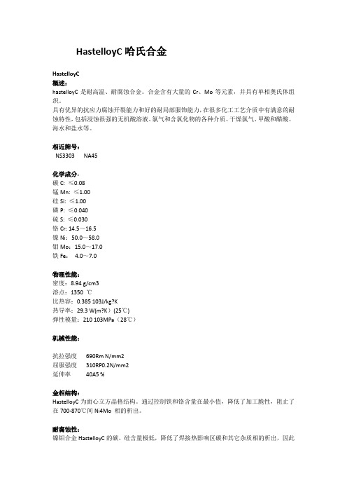
HastelloyC哈氏合金HastelloyC概述:hastelloyC是耐高温、耐腐蚀合金。
合金含有大量的Cr、Mo等元素,并具有单相奥氏体组织。
具有优异的抗应力腐蚀开裂能力和好的耐局部服饰能力,在很多化工工艺介质中有满意的耐蚀特性,包括浸蚀很强的无机酸溶液、氯气和含氯化物的各种介质、干燥氯气、甲酸和醋酸、海水和盐水等。
相近牌号:NS3303 NA45化学成分:碳C: ≤0.08锰Mn: ≤1.00硅Si: ≤1.00磷P: ≤0.040硫S: ≤0.030铬Cr: 14.5~16.5镍Ni:50.0~58.0钼Mo:15.0~17.0铁Fe:4.0~7.0物理性能:密度:8.94 g/cm3溶点:1350 ℃比热容:0.385 103J/kg?K热导率:29.3 W(m?K)(25℃)弹性模量:210 103MPa(28℃)机械性能:抗拉强度690Rm N/mm2屈服强度310RP0.2N/mm2延伸率40A5 %金相结构:HastelloyC为面心立方晶格结构。
通过控制铁和铬含量在最小值,降低了加工脆性,阻止了在700-870℃间Ni4Mo 相的析出。
耐腐蚀性:镍钼合金HastelloyC的碳、硅含量极低,降低了焊接热影响区碳和其它杂质相的析出,因此其焊缝也具有足够的抗腐蚀性。
合金Hastelloy C-2在还原性介质中具有很好的抗腐蚀性,如各种温度和浓度的盐酸溶液。
在中等浓度的硫酸溶液(或者含有一定量的氯离子)中也具有很好的抗腐蚀性。
同时也能用于醋酸和磷酸环境。
合金材料只有在适宜的金相状态和纯净的晶体结构时才能具有最好的耐腐蚀性。
应用领域:合金HastelloyC在化学、石化、能源制造和污染控制领域中有着广泛的应用,尤其是在硫酸、盐酸、磷酸、醋酸等工业中。
供应规格:棒、带、管、锻件、紧固件、法兰等协商供应加工:热加工1. 热加工温度范围1200℃~950℃,冷却方式为水冷或快速空冷。
2. 为保证最佳的防腐性能,热加工后应进行热处理,工件应直接加入已升温的热处理炉。
SL313网络多功能电力仪表说明书V1.2
3
盛隆电气集团有限公司
SL313 产品说明书 V1.2 版
SL313 适用于低压三相四线制系统、低压三相三线制系统、高压三相四线 制系统、高压三相三线制系统。具体接线方式请查看说明书中的接线方式说明。
装置测量参数有①:三相相/线电压,三相电流,零序电流,三相有功功率/ 总有功功率,三相无功功率/总无功功率,三相视在功率/总视在功率,三相功 率因数/总功率因数,三相电压/电流不平衡率,三相平均电压/电流,频率,有 功电度,无功电度等。
-1.000~ +1.000
45Hz~65Hz
0~9999999.9
0~9999999.9 4 路外部无源开关量接入
表 3 性能指标(执行标准为 GB/T 7261-2008,Q/SL10002-2013)
参数
指标
工作电源
AC:85~265V DC:80-300V
整机功耗
< 3VA
过载能力
持续 1.2 倍,瞬间电流 10 倍/1 秒,电压 2 倍/1 秒
开关量状态的显示,不提供平均电压和电流、零序电压和电流、总功率和总功率
因素的显示。
(2)三相三线制△接线方式时,功率和功率因素在显示和通信中都只提供总和值,分 相值无参考意义。显示面板只提供三相线电压、三相电流、总功率和总功率因素、
频率、有功电度、无功电度、开关量状态的显示。
5
盛隆电气集团有限公司
MN312 313 AC Current Probes用户手册说明书
AC Current ProbeModels MN312 and MN313User ManualDESCRIPTIONThe MN312/313 (Cat. #2116.24/2116.25) are the latest in compact AC current probes. Designed to meet the most stringent demands in industry and electrical contracting, they also meet the latest safety and performance standards. The probes have a measurement range up to 200Arms which make them perfect tools for measurements with DMMs, recorders, power and harmonic meters. The Models MN312/MN313 are compatible with any AC ammeter, multimeter, or other current measurement with an input impedance lower than 1 . To achieve the stated accuracy, use the MN312/MN313 with an ammeter having an accuracy of 0.75% or better.WARNINGThe safety warnings are provided to ensure the safety of personnel and proper operation of the instrument. Read the instruction completely.•Use caution on any circuit: potentially high voltages and currents may be present and may posea shock hazard.•Do not use the probe if damaged. Always connect the current probe to the measuring device before it is connected around the conductor•Do not use on non-insulated conductor with a potential to ground greater than 600V CAT III pollution 2. Use extreme caution when clamping around bare conductors or bus bars.• Before each use, inspect the probe; look for cracks in housing or output cable insulation.• Do not use clamp in wet environment or in locations that hazardous gases exist.• Do not use the probe anywhere beyond the tactile barrier.INTERNATIONAL ELECTRICAL SYMBOLSThis symbol signifies that the current probe is protected by double or reinforced insulation. Useonly factory specified replacement parts when servicing the instrument.This symbol signifies CAUTION! and requests that the user refer to the user manual beforeusing the instrument.This is a type A current sensor. This symbol signifies that application around and removal fromHAZARDOUS LIVE conductors is permitted.DEFINITION OF MEASUREMENT CATEGORIESCAT IV: For measurements performed at the primary electrical supply (<1000V) such as on primaryovercurrent protection devices, ripple control units, or meters.CAT III: For measurements performed in the building installation at the distribution level such as on hardwired equipment in fixed installation and circuit breakers.CAT II: For measurements performed on circuits directly connected to the electrical distribution system.Examples are measurements on household appliances or portable tools.RECEIVING YOUR SHIPMENTUpon receiving your shipment, make sure that the contents are consistent with the packing list. Notify your distributor of any missing items. If the equipment appears to be damaged, file a claim immediately with the carrier and notify your distributor at once, giving a detailed description of any damage.ELECTRICAL SPECIFICATIONS Nominal Range: 150AMeasurement Range: 0.1 to 200A Transformation Ratio: 1000:1Output Signal: 1mA/A on 1ΩAccuracy and Phase Shift*: Accuracy:0.1 to 1A: 2.0% Reading ± 0.02mA1 to 80A: 1% Reading ± 0.02mA80 to 100A: 1.5% Reading ± 0.1mA100 to 150A: 2.5% Reading ± 0.5mA150 to 200A: not specified Phase Shift:0.1 to 1A: Not Specified1 to 20A: ≤ 3°20 to 80A: ≤ 2°80 to 150A: ≤ 2.5°*Reference conditions: 20°C to 26°C, 20 to 75% RH, external magnetic field <40 A/m, 48 to 65Hz sine wave, distortion factor less than 1%, no DC component, no external current carrying conductor, test sample centered. Load impedance 1Ω.Frequency Range: 40 to 10kHzLimit Operating Conditions:200A permanently to 1kHz;Derating above 3kHz: 200A x (1/0.333 F), F in kHz2Crest Factor:3 @ 200A peak max with an error (due to CF) of 3%Open Secondary Voltage:8V peak max.Working Voltage:600VrmsCommon Mode Voltage:600VrmsInfluence of Adjacent Conductor:< 15mA/A at 50HzInfluence of DC (< 10A) on AC signal:< 10%Influence of Conductor Position in Jaw: 0.5% of mA output @ 50/60HzInfluence of Frequency:40Hz to 1kHz: 5% of mV output1kHz to 10kHz: 15% of mV outputInfluence of Load:From 0.1Ω to 5Ω and 0.7V peak max< 0.5% for output < 0.5° for phaseInfluence of Temperature:≤ 200 ppm/°K, or 0.2% of mA output per 10°KInfluence of Humidity (10 - 90% RH):≤ 0.2% of mA output per 10°KMECHANICAL SPECIFICATIONSOperating Temperature:14° to 131°F (-10° to +55°C)Storage Temperature:-40° to 158°F (-40° to +70°C)Operating Relative Humidity:10-35°C 85% RH(without roll-off above 35°C)Maximum Cable Diameter:One Ø 0.78” (20mm), bus bar 20 x 5mmCase Protection:IP 40 (IEC 529)Drop Test:Test per IEC 68-2-32:1.0m drop on 38mm of Oak on concrete.Mechanical Shock:Test per IEC 68-2-27 Vibration:Test per IEC 68-2-6Dimensions:5.47 x 2.00 x 1.18" (139 x 51 x 30mm)Weight:6.5oz (180g)Polycarbonate Material:Jaws: Polycarbonate with 10% fiberglass charge, Red UL 94 V0Case: Polycarbonate 920A GrayOpening Operations - Life:> 50,000Output:MN312: Two standard safety banana jacks (4mm) MN313: Double/reinforced insulated 5 ft (1.5m)lead with safety 4mm banana plug SAFETY SPECIFICATIONSAC Current Probe MN312 ................. Cat #2116.24 AC Current Probe MN313 ................. Cat #2116.25E192383Electrical:Double insulation or reinforced insulation between the primary or secondary and the outer case of the handle conforms to IEC 1010-2-32.Common Mode Voltage:600V Category III, Pollution Degree 2 Electromagnetic Compatibility:Emission and immunity in an industrial environment according to EN61326-1ORDERING INFORMATIONAccessories:Lead, set of 2, 5 ft PVC color-coded(red/black) with 4mm straight/straight banana plugs(Rated 1000V CAT IV, 15A, UL, V2)....Cat #5100.07 Banana plug adapter(to non-recessed plug) ....................... Cat #1017.45 3OPERATIONPlease make sure that you have already read and fully understand the WARNING section on page 1. Making Measurements with the AC Current Probe Model MN312/MN313∙Connect the black lead of the current probe to “common” and the red lead to the AC current input on your DMM or other current measuring instrument. Select the appropriate current range (400mA AC range). Clamp the probe around the conductor to be tested with the arrow pointed toward the load. If the reading is less than 10mA, select the lower range until you obtain the best resolution. Read the value display on the DMM and multiply it by the probe ratio (1000/1). (If reading = 102mA, the current flowing through the probe is 102mA x 1000 = 102000mA AC = 102A).∙For best accuracy, avoid if possible, the proximity of other conductors which may create noise.Tips for Making Precise Measurements∙When using a current probe with a meter, it is important to select the range that provides the best resolution. Failure to do this may result in measurement errors.∙Make sure that probe jaw mating surfaces are free of dust and contamination. Contaminants cause air gaps between the jaws, increasing the phase shift between primary and secondary. It is very critical for power measurement.MAINTENANCE:Warning∙For maintenance use only original factory replacement parts.∙To avoid electrical shock, do not attempt to perform any servicing unless you are qualified to do so.∙To avoid electrical shock and/or damage to the instrument, do not get water or other foreign agents into the probe.CleaningTo ensure optimum performance, it is important to keep the probe jaw mating surfaces clean at all times. Failure to do so may result in error in readings. To clean the probe jaws, use very fine sand paper (fine 600) to avoid scratching the jaw, then gently clean with a soft oiled cloth.REPAIR AND CALIBRATIONYou must contact our Service Center for a Customer Service Authorization number (CSA#). This will ensure that when your instrument arrives, it will be tracked and processed promptly. Please write the CSA# on the outside of the shipping container.Chauvin Arnoux®, Inc. d.b.a. AEMC® Instruments15 Faraday Drive ∙ Dover, NH 03820 USA(800)945-2362(Ext.360)•(603)749-6434(Ext.360)•***************(Or contact your authorized distributor)NOTE: All customers must obtain a CSA# before returning any instrument.TECHNICAL AND SALES ASSISTANCEIf you are experiencing any technical problems, or require any assistance with the proper use or application of this instrument, please contact our technical hotline:(800)343-1391•(508)698-2115•********************LIMITED WARRANTYThe current probe is warranted to the owner for a period of two year s from the date of original purchase against defects in manufacture. This limited warranty is given by AEMC® Instruments, not by the distributor from whom it was purchased. This warranty is void if the unit has been tampered with, abused or if the defect is related to service not performed by AEMC® Instruments.Full warranty coverage and product registration is available on our website at:/warranty.html.Please print the online Warranty Coverage Information for your records.99-MAN 100159 v13 12/20。
加特NER 型号 GN 313 弹簧销 钢 不锈钢, 销钉在正常位置处收回 说明书

ELESA and GANTER models all rights reserved in accordance with the law.Always mention the source when reproducing our drawings.8048I n d e x i n g e l e m e n tsGN 313Spring boltsSteel / Stainless Steel, Pin retracted in normal posi-tionSPECIFICATION Types-T ype A : with knob, without lock nut -T ype AK : with knob, with lock nut-T ype D : without knob, without lock nut -T ype DK : without knob, with lock nut Identification no.-Version 1: Plunger without internal thread -Version 2: Plunger with internal thread Guide (Threaded socket)Steel ST blackenedGuide (Threaded socket)Stainless Steel AISI 303 NI PinStainless Steel-AISI 303-chemically nickel plated KnobPlastic (Polyamide PA) -black, matt -not removable INFORMATIONThe pin of the spring bolts GN 313 does not protrude in the inoperative position.It can be operated manually or in T ype D and DK mechanically (pneumatic cylinder, cam plate, etc.) when it will protrude only aslong as it is operated.Using the internal thread at identification 2 on the pressure side, special pressure bolts or a rod arrangement can be operated, for instance.TECHNICAL INFORMATION-ISO-Fundamental T olerances (see page A21) -Stainless Steel characteristics (see page A26) -Plastic characteristics (see page A2) -Load rating information (see page A42)7/20208058I n d e x i n g e l e m e n ts 2/2ELESA and GANTER models all rights reserved in accordance with the law.Always mention the source when reproducing our drawings.GN 313Spring boltsComplete with type index of the Indexing plungers (A, AK, D or DK)*AAKDDKWeight type A7/2020。
313轴承尺寸参数
313轴承尺寸参数313轴承是一种常见的滚动轴承,其尺寸参数对于机械设备的运行至关重要。
下面将介绍313轴承的尺寸参数及其在工程应用中的意义。
1. 内径(d):313轴承的内径是指轴承内圈的直径,通常用毫米(mm)表示。
内径的大小决定了轴承的装配尺寸和轴的大小选择。
在选择轴承时,需要确保轴的直径略大于轴承的内径,以确保良好的配合。
2. 外径(D):313轴承的外径是指轴承外圈的直径,也通常用毫米(mm)表示。
外径的大小决定了轴承的外部安装尺寸,以及轴承与外部环境的配合。
在安装轴承时,需要确保外径与轴承座孔或外壳的尺寸相匹配,以保证轴承的稳定性和正常运行。
3. 宽度(B):313轴承的宽度是指轴承的厚度,通常用毫米(mm)表示。
宽度的大小决定了轴承的承载能力和刚度。
较宽的轴承能够承受更大的径向和轴向载荷,但也会增加摩擦和能量损失。
因此,在选择轴承时,需要根据具体的工作条件和载荷要求来确定合适的宽度。
4. 动态负荷额定值(C):313轴承的动态负荷额定值是指在标准条件下,轴承能够承受的最大动荷载。
它通常以牛顿(N)表示。
动态负荷额定值是根据轴承材料、几何形状和润滑条件等因素计算得出的,可以帮助用户选择合适的轴承来满足工作条件下的负荷要求。
5. 静态负荷额定值(Co):313轴承的静态负荷额定值是指在静止状态下,轴承能够承受的最大静荷载。
它通常以牛顿(N)表示。
静态负荷额定值是根据轴承材料和几何形状等因素计算得出的,可以帮助用户选择合适的轴承来满足停机或静止负荷条件下的要求。
6. 极限转速(n):313轴承的极限转速是指轴承在标准条件下能够承受的最大转速。
它通常以转每分钟(rpm)表示。
极限转速是根据轴承的结构和润滑条件等因素计算得出的,可以帮助用户确定轴承的使用范围和工作条件。
313轴承的尺寸参数是设计和选择轴承时必须考虑的重要因素。
合理选择尺寸参数可以提高轴承的运行效率和寿命,同时也能够减少故障和维修成本。
- 1、下载文档前请自行甄别文档内容的完整性,平台不提供额外的编辑、内容补充、找答案等附加服务。
- 2、"仅部分预览"的文档,不可在线预览部分如存在完整性等问题,可反馈申请退款(可完整预览的文档不适用该条件!)。
- 3、如文档侵犯您的权益,请联系客服反馈,我们会尽快为您处理(人工客服工作时间:9:00-18:30)。
Direct Drive Voice/Dual Tone Melody Controller 1 INTRODUCTIONSNC313 is a 1-channel voice synthesizer and dual-tone melody IC with PWM direct drive circuit. It built-in a 4-bit tiny controller with one 4-bit input port and two 4-bit I/O ports. By programming through the tiny controller in SNC313, user’s varied applications including voice section combination, dual-tone melody, key trigger arrangement, output control, and other logic functions can be easily implemented.2 FEATURESSingle power supply 2.4V – 5.5V7 seconds voice capacity are provided (@6KHZ sample rate)Built in a 4-bit tiny controllerOne 4-bit input port and two 4-bit I/O ports are provided128*4 bits RAM are provided24K*10 ROM size are provided for voice data and programMaximum 16k program ROM is providedReadable ROM code dataIR carrier signal is providedBuilt in a high quality speech synthesizerAdaptive playing speed from 2.5k-20kHz is providedOne voice channel plus Dual-Tone MelodyBuilt in a PWM Direct Drive circuit and a fixed current D/A outputSystem clock : 2MHzLow Power ResetDirect Drive Voice/Dual Tone Melody Controller 3 Block Diagram4 PIN ASSIGNMENTSymbol I/O Function DescriptionP13 ~ P10 I Bit3 ~ Bit0 of Input port 1P23 ~ P20 I/O Bit3 ~ Bit0 of I/O port 2P33 ~ P30 I/O Bit3 ~ Bit0 of I/O port 3VDD P Positive power supplyGND P Negative power supplyRST I Reset pin (active high)OSC O Oscillator / Crystal OutOutput of PWM or DA outputPositiveBUO1/VO OBUO2 O Negative Output of PWMDirect Drive Voice/Dual Tone Melody Controller5 FUNCTION DESCRIPTIONS 5.1. OscillatorSNC313 accept RC type oscillator for system clock. The typical circuit diagram for oscillator is listed as follow.rOSCVCCRC Oscillator5.2. ROMSNC313 contains substantial 24K words (10-bit) internal ROM. Program, voices and other data are shared with this same 24K words ROM.5.3. RAMSNC313 contains 128 nibbles RAM. The 128 nibbles RAM are divided into eight pages (page 0 to page 7, 16 nibbles RAM on each page). In our programming structure, users can easily define and locate RAM page in the program. For instance, users can use the instructions, PAGEn (n=0 to 7) to switch and indicate the RAM page. Besides, users can use direct mode, M0 ~ M15 in the data transfer type instructions, to access all 16 nibbles of each page.5.4. Power Down Mode“End” instruction will power down SNC313 and enable IC to consume fewer current for power saving. (<3uA @VDD=3V and <5uA @VDD=5V) Please be aware that when the power down mode is activated in SNC313, any valid data transition (L H or H L) occurring on any input port (P1) or IO ports (P2 and P3) will lead SNC313 back to normal operation mode.5.5. Sampling Rate CounterThe unique sampling rate counter is designed in voice channel to be able to play diverse voices at different sample playing rates. The playing rate can be adaptively set up among from the wide ranges of 2.5KHz to 20KHz. This feature makes voice close to its original source and yield the better voice quality.5.6. Dual-Tone GeneratorA dual-tone melody generator is included to generate 2-channel music songs with a pleasant square-wave-like timbre. The pitch range of each tone generator is as wide as 4 octaves (48 different notes totally). The output of dual-tone generator can be mixed with the output of voice synthesizer to achieve voice playing with BGM (background music). Additionally, Sonix provides a numbered-musical-notation representation to help users compose their songs. Further, a MIDI (1.0) file translator can convert MIDI files into Sonix format.5.7. I/O PortsP1 is a 4-bit input port and P2/P3 are two 4-bit I/O ports. Any bit of P2 and P3 can be programmed as either input or output port individually. Any valid data transition (H L or L H) of P1, P2 and P3 can reactivate the chip when the chip is in power-down mode.Input Port Configuration (P10~P13)I/O Port Configuration (P20~P23, P30~P33)Note: weak N-MOS’s can serve as pull-low resistor.5.8. IR FunctionP33 can be modulated with 38.5KHz square wave before sent out to P33 pin. The IR signal can be achieved by this modulated signal.5.9. DAC & PWMSNC313 is an advanced chip to be designed having two optimal methods to play out the voices. One is DAC and the other is PWM. Upon user’s applications, user can select either DAC or PWM in his design. Please be aware that only one method can be activated at a time.DAC: A 7-bit current type digital-to-analog converter is built-in SNC313. The relationship between input digital data and output analog current signal is listed in the following table. Also, the recommended application circuit is illustrated as follows.Input data Typical value of output current (mA)0 01 3/127…N n*(3/127)…127 3DAC outputPWM: A PWM (pulse width modulation) circuit is built-in SNC313. PWM can convert input digital data into pulse trains with suitable different pulse width. The maximum resolution of PWM is 7 bits. Two huge output stage circuits are designed in SNC313. With this advanced circuit, the chip is capable of driving speaker directly without external transistors. The recommended application circuit is illustrated as follows.PWM OutputDirect Drive Voice/Dual Tone Melody Controller 6 ABSOLUTE MAXIMUM RATINGItems Symbol Min Max Unit.Supply Voltage V DD-V -0.3 6.0 VInput Voltage V IN V SS-0.3 V DD+0.3 VOperating Temperature T OP 0 55.0 o CStorage Temperature T STG -55.0 125.0 o C7 ELECTRICAL CHARACTERISTICSItem Sym. Min. Typ. Max. Unit Condition Operating Voltage V DD 2.4 3.0 5.5 VStandby current I SBY - 2.05.0 - u A V DD=3V , no loadV DD=4.5V, no loadOperating Current I OPR - 300700 - u A V DD=3V , no loadV DD=4.5V, no loadInput current ofP1, P2, P3I IH - 3.0 10.0 u A V DD=3V,V IN=3VDrive current ofP2, P3I OD- 4 - m A V DD=3V,V O=2.4VSink Current ofP2, P3I OS- 6 - m A V DD=3V,V O=0.4VDrive current ofP2, P3I OD- 5 - m A V DD=4.5V,V O=3.9VSink Current ofP2, P3I OS- 9 - m A V DD=4.5V,V O=0.4V Drive current of Buo1 I OD 100 120 - m A VDD=3V,Buo1=1.5V Sink Current of Buo1 I OS 100 120 - m A VDD=3V,Buo1=1.5V Drive Current of Buo2 I OD 100 120 - m A VDD=3V,Buo2=1.5V Sink Current of Buo2 I OS 100 120 - m A VDD=3V,Buo2=1.5V Oscillation Freq. F OSC - 2.0 - MHzV DD=3VIR Carrier Frequency Fir - 38.5 - KHz Fosc=2MHzDirect Drive Voice/Dual Tone Melody Controller 8 ROSC PerformanceROSC frequency vs VDD (Typical value, R=120KΩ)ROSC frequency vs. VDD (For various R)Direct Drive Voice/Dual Tone Melody Controller 9 APPLICATION CIRCUITD/A Speaker Output16 Scan KeysNote: The C1 (0.1uF) between Power and GND should be closed to VDD pin of SNC313 as possible.Direct Drive Voice/Dual Tone Melody Controller10 BONDING PAD12345678910111213141516171819P10P11P12P13P20P21OSCG N DB U O 1V D DB U O 2G N D P22P23P30P31P32P33RST (0.00,0.00)SNC313Note: The substrate MUST be connected to Vss in PCB layout.Direct Drive Voice/Dual Tone Melody Controller DISCLAIMERThe information appearing in SONiX web pages (“this publication”) is believed to be accurate.However, this publication could contain technical inaccuracies or typographical errors. The reader should not assume that this publication is error-free or that it will be suitable for any particular purpose. SONiX makes no warranty, express, statutory implied or by description in this publication or other documents which are referenced by or linked to this publication. In no event shall SONiX be liable for any special, incidental, indirect or consequential damages of any kind, or any damages whatsoever, including, without limitation, those resulting from loss of use, data or profits, whether or not advised of the possibility of damage, and on any theory of liability, arising out of or in connection with the use or performance of this publication or other documents which are referenced by or linked to this publication.This publication was developed for products offered in Taiwan. SONiX may not offer the products discussed in this document in other countries. Information is subject to change without notice. Please contact SONiX or its local representative for information on offerings available. Integrated circuits sold by SONiX are covered by the warranty and patent indemnification provisions stipulated in the terms of sale only. The application circuits illustrated in this document are for reference purposes only. SONIX DISCLAIMS ALL WARRANTIES, INCLUDING THE WARRANTY OF MERCHANTABILITY OR FITNESS FOR ANY PURPOSE. SONIX reserves the right to halt production or alter the specifications and prices, and discontinue marketing the Products listed at any time without notice. Accordingly, the reader is cautioned to verify that the data sheets and other information in this publication are current before placing orders.Products described herein are intended for use in normal commercial applications. Applications involving unusual environmental or reliability requirements, e.g. military equipment or medical life support equipment, are specifically not recommended without additional processing by SONIX for such application.Direct Drive Voice/Dual Tone Melody Controller。
