L6258E_DataSheet
数据手册_HR6P60HL_Datasheet_C V2.2
关于芯片的开发环境
海尔 MCU 芯片具有完整的软/硬件开发环境,并受知识产权保护。选择上海海尔集成电路有限公司或其指 定的第三方公司的汇编器、编译器、编程器、硬件仿真器开发环境,必须遵循与芯片相关的规定和说明。
注:在产品开发时,如遇到不清楚的地方,请用下述联系方式与上海海尔集成电路有限公司联系。
V2.2 版权所有©上海海尔集成电路有限公司
关于芯片的 ESD 防护措施
海尔 MCU 芯片具有满足工业级 ESD 标准保护电路。 建议用户根据芯片存储/应用的环境采取适当静电防护 措施。应注意应用环境的湿度;建议避免使用容易产生静电的绝缘体;存放和运输应在抗静电容器、抗静 电屏蔽袋或导电材料容器中;包括工作台在内的所有测试和测量工具必须保证接地;操作者应该佩戴静电 消除手腕环手套,不能用手直接接触芯片等。
HR6P60HL 数据手册
海尔 MCU 芯片使用注意事项
关于芯片的上/下电 海尔 MCU 芯片具有独立电源管脚。当 MCU 芯片应用在多电源供电系统时,应先对 MCU 芯片上电,再 对系统其他部件上电;反之,下电时,先对系统其他部件下电,再对 MCU 芯片下电。若操作顺序相反则
可能导致芯片内部元件过压或过流,从而导致芯片故障或元件退化。具体可参照芯Hale Waihona Puke 的数据手册说明。关于芯片的时钟
海尔 MCU 芯片具有内部和外部时钟源。内部时钟源会随着温度、电压变化而偏移,可能会影响时钟源精 度;外部时钟源采用陶瓷、晶体振荡器电路时,建议使能起振延时;使用 RC 振荡电路时,需考虑电容、 电阻匹配; 采用外部有源晶振或时钟输入时, 需考虑输入高/低电平电压。 具体可参照芯片的数据手册说明。
3. 2
第 4 章 4. 1 4. 2 4. 3 4. 4 4. 5
TLE6288中文资料
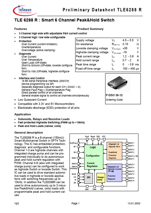
• 3 Channel high / low side configurable
• Protection
Supply voltage
VS
4.5 – 5.5 V
Over Current (current limitation) Overtemperature Overvoltage (active clamping)
Current Regulation
Channel 4 -6
Highside/ Lowside
150 mΩ
SPI
Charge- Protection
pump
Diagnosis
GND FSIN VCP
DOUT 1 SOUT 1 DOUT 2 SOUT 2 DOUT 3 / VB SOUT 3
DOUT 4 SOUT 4 DOUT 5 SOUT 5 DOUT 6 SOUT 6
DOUT 2 SOUT 2
DOUT 1 SOUT 1
DOUT 4 SOUT 4
DOUT 5 SOUT 5
DOUT 6 SOUT 6
FSIN
GND
VCP
Vp2
Page 2
13.01.2003
元器件交易网
Preliminary Datasheet TLE6288 R
2. Functional description
Channel 4..6: Either High or Low Side Drive is configurable (by SPI) Open load detection and switch bypassed detection can be deactivated by SPI
Vp2
Page 3
低功耗半导体 LP6498A 600KHz 36V 1.2A 同步降压转换器 初步数据表说明书

600KHz 36V/1.2A Synchronous Step-down ConverterGeneral DescriptionThe LP6498A is a synchronous step-down regulatorfromahighvoltageinputsupply.Operating with an input voltage range from 4.5V to 30V.1.2A continuous output current .The converter integrates a main switch and a synchronous rectifier for high efficiency without an external Schottky diode. LP6498A Requires a minimum number of readily available standard external components.over current protection and thermal shutdown . output short circuit protection. The LP6498A converters are available in the industry standard SOT23-6 packages.Order InformationLP6498A□ □ □F: Pb-FreePackage TypeB6:SOT23-6Applications✧ Car Charger / Adaptor✧ Pre-Regulator for Linear Regulators ✧ Distributed Power Systems✧ USB Dedicated Charging Ports (DCP)Features◆ Input Voltage Range: 4.5V to 30V ◆ Output Voltage Range: 0.8V to 12V◆ 1200mA Load Current ◆ Up to 93% Efficiency◆ 600KHz Switching Frequency◆ Short Circuit Protection ◆ Thermal Fault Protection ◆ S O T 23-6 Package◆ RoHS Compliant and 100% Lead (Pb)-FreeTypical Application CircuitMarking InformationVINFunctional Pin DescriptionPin DescriptionNC No connection.GND Ground.FB Feedback Input.Vout=(R1R2+1)×V FBFunction DiagramAbsolute Maximum Ratings✧VIN\SW \EN to GND ---------------------------------------------------------------------------------------------- -0.3V to 36V ✧VOUT\LED\RV\FB to GND --------------------------------------------------------------------------------------- -0.3V to 6.5V ✧Maximum Junction Temperature -------------------------------------------------------------------------------------- 150°C ✧Storage Temperature ------------------------------------------------------------------------------------------ -65℃ to 165℃✧Operating Ambient Temperature Range (TA) ------------------------------------------------------------- -20℃ to 85°C ✧Maximum Soldering Temperature (at leads, 10 sec) ------------------------------------------------------------- 260°CNote 1. Stresses beyond those listed under “Absolute Maximum Ratings” may cause permanent damage to the device. These are stress ratings only, and functional operation of the device at these or any other conditions beyond those indicated in the operational sections of the specifications is not implied.Exposure to absolute maximum rating conditions for extended periods may affect device reliability.Thermal Information✧Maximum Power Dissipation (SOT23-6, P D, T A=25℃) ------------------------------------------------------------ 0.6W ✧Thermal Resistance (SOT23-6, θJA) ------------------------------------------------------------------------------ 200℃/W ESD Susceptibility✧HBM(Human Body Mode) -------------------------------------------------------------------------------------------------- 2KV ✧MM(Machine Mode) --------------------------------------------------------------------------------------------------------- 200VElectrical CharacteristicsV IN=12V, V EN=5V, T A=25℃, unless otherwise notedHiccup Time 6Soft-start Time0.8Oscillator Frequency 600Typical Operating CharacteristicsOperation InformationFunctional DescriptionThe LP6498A is a switch-mode step-down DC-DC converter. The device operates at a fixed 600KHz switching frequency, and uses a slope compensated current mode architecture. This step-down DC-DC converter can supply up to 1.2A output current at input voltage range from 4.5V to 30V. It minimizes external component size and optimizes efficiency at the heavy load range. The integrated slope compensation allows the device to remain stable over a wider range of inductor values so that smaller values (6.8μH to 22μH) with lower DCR can be used to achieve higher efficiency. Layout GuidanceWhen laying out the PCB board, the following layout guideline should be followed to ensure proper operation of the LP6498A:1. The power traces, including the GND trace, the SW trace and the IN trace should be kept short, direct and wide to allow large current flow. The L connection to the SW pins should be as short as possible. Use several VIN pads when routing between layers.2. The input capacitor (C IN) should connect as closely as possible to VIN and GND to get good power filtering.Packaging InformationSOT23-6。
2SK3378ENTL-E中文资料(renesas)中文数据手册「EasyDatasheet - 矽搜」

Renesas Electronics product for an application categorized as “Specific” or for which the product is
not intended where you have failed to obtain the prior written consent of Renesas Electronics. The quality grade of each Renesas Electronics product is “Standard” unless otherwise expressly
5. When exporting the products or technology described in this document, you should comply with the applicable export control laws and regulations and follow the procedures required by such laws and regulations. You should not use Renesas Electronics products or the technology described in this document for any purpose relating to military applications or use by the military, including but not limited to the development of weapons of mass destruction. Renesas Electronics products and technology may not be used for or incorporated into any products or systems whose manufacture, use, or sale is prohibited under any applicable domestic or foreign laws or regulations.
模组说明书:Modicon M258 TM258LF66DT4L
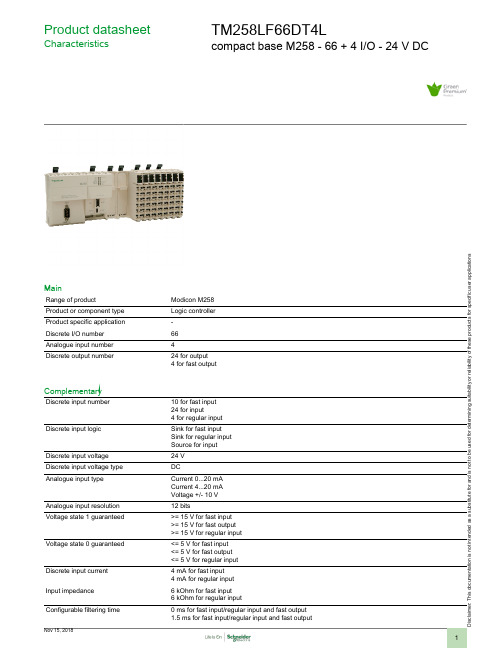
i s c la i me r : T h i s d o c u m e n t a t i o n i s n o t i n t e n d e d a s a s u b s t i t u t ef o r a n d i s n o t t o b e u s e d f o r d e t e r m i n i ng s u i t a b i l i t y o r r e l i a b i l i t y o f th e s e p r o d u c t s f o r s p e ci f i c u s e r a p p l i c a t i o n sProduct datasheetCharacteristicsTM258LF66DT4Lcompact base M258 - 66 + 4 I/O - 24 V DCMainRange of productModicon M258Product or component type Logic controller Product specific application -Discrete I/O number 66Analogue input number 4Discrete output number24 for output 4 for fast outputComplementaryDiscrete input number10 for fast input 24 for input4 for regular input Discrete input logicSink for fast input Sink for regular input Source for input Discrete input voltage 24 V Discrete input voltage type DCAnalogue input typeCurrent 0...20 mA Current 4...20 mA Voltage +/- 10 V Analogue input resolution 12 bitsVoltage state 1 guaranteed>= 15 V for fast input >= 15 V for fast output >= 15 V for regular input Voltage state 0 guaranteed<= 5 V for fast input <= 5 V for fast output <= 5 V for regular input Discrete input current 4 mA for fast input 4 mA for regular input Input impedance 6 kOhm for fast input 6 kOhm for regular inputConfigurable filtering time0 ms for fast input/regular input and fast output 1.5 ms for fast input/regular input and fast output12 ms for fast input/regular input and fast output4 ms for fast input/regular input and fast outputAnti bounce filtering 2 µs...4 ms (configurable) fast input/regular input and fast outputCable distance between devices30 m for fast input30 m for fast output30 m for regular input500 Vrms ACIsolation between channels andinternal logicIsolation between channels NoneDiscrete output logic SourceDiscrete output voltage24 V DCOutput voltage limits19.2...28.8 VDiscrete output current 4 mA for fast output[Us] rated supply voltage24 V DC for embedded expert modules power24 V DC for I/O power segment24 V DC for main supplySupply voltage limits20.4...28.8 V[In] rated current0.04 A for embedded expert modules power0.31 A for main supply10 A for I/O power segmentPeak current<= 100 kA during <= 70 s main supply<= 25 kA during <= 500 s I/O power segment<= 50 kA during <= 150 s embedded expert modules power<= 1.2 kA during > 70 s main supplyPower consumption in W<= 18.11 WExecution time per instruction22 ns : BooleanMemory description Flash 128 MBInternal RAM 64 MBRealtime clock With user calibration realtime clock, drift: <= 6 s/monthWithout any user calibration realtime clock, drift: < 30 s/month at 25 °CData backed up Variables of type retain and retain persistent CR2477M Renata, 1.5 years autonomy Integrated connection type 1 CANopen male SUB-D 9, CANopen master1 isolated serial link female RJ45, Ethernet Modbus TCP/IP slave (10BASE-T/100BASE-TX)2 free slots PCI1 isolated serial link female RJ45, Modbus master/slave RTU/ASCII or character mode ASCII(RS232/RS485), 300...115200 bps1 isolated serial link mini B USB, 480 Mbit/s1 isolated serial link USB type A, 480 Mbit/sTransmission rate125 kbit/s for bus length of 500 m, CANopen250 kbit/s for bus length of 250 m, CANopen50 kbit/s for bus length of 1000 m, CANopen500 kbit/s for bus length of 100 m, CANopen10 kbit/s for bus length of 5000 m, CANopen1000 kbit/s for bus length of 4 m, CANopen20 kbit/s for bus length of 2500 m, CANopen800 kbit/s for bus length of 25 m, CANopenCounting input number8 counting input(s) 200 kHzLocal signalling 1 LED per channel for I/O state1 LED for CAN0 STS1 LED for MBS COM1 LED green/red for APP01 LED green/red for APP11 LED green/red for Eth NS (Ethernet network status)1 LED green/red for Eth ST (Ethernet status)1 LED green/red for RUN/MS (module status)1 LED green/red for USB host1 LED green/yellow for Eth LA (Ethernet activity)1 LED red for BATT (battery status)Marking CEMounting support Symmetrical DIN railWidth262.5 mmHeight99 mmDepth85 mmProduct weight0.8 kgEnvironmentStandardsCSA C22.2 No 142IEC 61131-2UL 508CSA C22.2 No 213Product certificationsCSA C-Tick cULus GOST-RAmbient air temperature for operation0...55 °C without derating factor horizontal installation 0...60 °C with derating factor horizontal installation 0...50 °C vertical installation Ambient air temperature for storage -25...70 °CRelative humidity 5...95 % without condensation IP degree of protection IP20 conforming to IEC 61131-2Pollution degree 2 conforming to IEC 60664Operating altitude 0...2000 m Storage altitude 0...3000 mVibration resistance 1 gn 8.4...150 Hz DIN rail 3.5 mm 5...8.4 Hz DIN rail Shock resistance15 gn for 11 msResistance to electrostatic discharge 4 kV on contact conforming to EN/IEC 61000-4-28 kV in air conforming to EN/IEC 61000-4-2Resistance to electromagnetic fields 1 V/m 2...2.7 GHz conforming to EN/IEC 61000-4-310 V/m 80...2000 MHz conforming to EN/IEC 61000-4-3Resistance to fast transients1 kV I/O conforming to EN/IEC 61000-4-41 kV shielded cable conforming to EN/IEC 61000-4-42 kV power lines conforming to EN/IEC 61000-4-4Surge withstand0.5 kV differential mode conforming to EN/IEC 61000-4-51 kV common mode conforming to EN/IEC 61000-4-5Disturbance radiated/conductedCISPR 11Offer SustainabilitySustainable offer status Green Premium productRoHS (date code: YYWW)Compliant - since 1039 - Schneider Electric declaration of conformity Schneider Electric declaration of conformity REAChReference not containing SVHC above the threshold Reference not containing SVHC above the threshold Product environmental profile AvailableProduct environmental Product end of life instructionsAvailableEnd of life manualContractual warrantyWarranty period18 monthsDimensions DrawingsControllerDimensionsTM5 System Wiring RecommendationsWire Sizes to Use with Removable Spring Terminal BlocksExternal Power SuppliesWiring Diagram of the Controller Power Distribution Module(1)Internal electronics(2)24 Vdc I/O power segment integrated into the bus bases (3)PS1/PS2: External isolated SELV power supply 24 Vdc (4)External fuse, Type T slow-blow, 3 A 250 V (5)External fuse, Type T slow-blow, 2 A 250 V(6)External fuse, Type T slow-blow, 10 A max., 250 V。
IT6251_Datasheet_v02
IT6251LVDS to DispalyPort 1.1a TransmitterPreliminary Datasheet Specification V0.2ITE TECH. INC.General DescriptionThe IT6251 is a high-performance single-chip De-SSC LVDS to DisplayPort converter. Combined with LVDS receiver and DisplayPort Transmitter, the IT6251 supports LVDS input and DisplayPort 1.1a output by conversion function. The build-in LVDS receiver can support single-link and dual-link LVDS inputs, and the build-in DisplayPort transmitter is fully compliant with DisplayPort 1.1a specification. With high speed LVDS RX, the IT6251 can support resolution up to 1080P and UXGA and 10-bit deep colors.In order to reduce the EMI noise on legacy system application, the traditional LVDS source will transmit differential signals with spread spectrum, but this spread spectrum does not be allowed for DisplayPort protocol. The IT6251 also build-in unique De-SSC ( De-Spread Spectrum ) function , it can help customers easily to adopt the IT6251 on the EMI-concerned platform, with SSC has been generated from LVDS source processors.Features ( LVDS RX )• Support LVDS Input modes: Single Link, Dual Link• Support input clock rate up to 165MHz• Support input color depth up to 10bit• Support De-SSC ( De-Spread Spectrum )• Support Data Mapping: Open LDI / JEIDA , VESAFeatures (DisplayPort TX)DisplayPort 1.1a transmitterCompliant with DisplayPort 1.1aSupporting two link speeds, HBR(2.7Gbps) and RBR(1.62Gbps).Various video input interface supporting digital video standards such as:18/24/30/36-bit RGB4:4:4Software programmable DispalyPort output swing and pre-emphasis levelEmbedded full-function pattern generatorMCCS over AUX channelIntelligent, programmable power managementFeatures ( Combined )• Support up to Full-HD/1080P , and WQXGA(2560x1600 RB) display format• Support deep color depth up to 10bit• 64-pin QFN (9mm x 9mm) package• RoHS Compliant ( 100% Green available )Ordering InformationModel Temperature Range Package Type Green/Pb free Option IT6251 0~70 64-pin QFN GreenPin DiagramFigure 1. IT6251 pin diagramPin DescriptionLVDS front-end interface pinsPin Name Direction Description Type Pin No. RXNA1 Analog LVDS first link negative input LVDS 17 RXPA1 Analog LVDS first link positive input LVDS 18 RXNB1 Analog LVDS first link negative input LVDS 19 RXPB1 Analog LVDS first link positive input LVDS 20 RXNC1 Analog LVDS first link negative input LVDS 22 RXPC1 Analog LVDS first link positive input LVDS 23 RXND1 Analog LVDS first link negative input LVDS 27 RXPD1 Analog LVDS first link positive input LVDS 28 RXNE1 Analog LVDS first link negative input LVDS 29 RXPE1 Analog LVDS first link positive input LVDS 30 RXNCLK Analog LVDS negative clock input LVDS 24 RXPCLK Analog LVDS positive clock input LVDS 25 RXNA2 Analog LVDS second link negative input LVDS 34 RXPA2 Analog LVDS second link positive input LVDS 35 RXNB2 Analog LVDS second link negative input LVDS 36 RXPB2 Analog LVDS second link positive input LVDS 37 RXNC2 Analog LVDS second link negative input LVDS 39 RXPC2 Analog LVDS second link positive input LVDS 40 RXND2 Analog LVDS second link negative input LVDS 42 RXPD2 Analog LVDS second link positive input LVDS 43 RXNE2 Analog LVDS second link negative input LVDS 44 RXPE2 Analog LVDS second link positive input LVDS 45Programming PinsPin Name Direction Description Type Pin No. SYSRSTN Input Hardware reset pin. Active LOW (5V-tolerant) LVTTL 7 PCSCL Input Serial Programming Clock for chip programming (5V-tolerant) LVTTL 14 PCSDA I/O Serial Programming Data for chip programming (5V-tolerant) LVTTL 15 PCADR Input Serial programming device address select LVTTL 13 HPD Input Hot Plug Detection (5V-tolerant) LVTTL 5DisplayPort front-end interface pinsPin Name Direction Description Type Pin No. TX3P Analog DisplayPort Lane 3 positive output DP 51 TX3N Analog DisplayPort Lane 3 negative output DP 50 TX2P Analog DisplayPort Lane 2 positive output DP 54 TX2N Analog DisplayPort Lane 2 negative output DP 53 TX1P Analog DisplayPort Lane 1 positive output DP 57 TX1N Analog DisplayPort Lane 1 negative output DP 56 TX0P Analog DisplayPort Lane 0 positive output DP 60 TX0N Analog DisplayPort Lane 0 negative output DP 59 TXAUXP Analog DisplayPort AUX channel positive signal DP 48 TXAUXN Analog DisplayPort AUX channel negative signal DP 47 XTALIN Analog DisplayPort AFE crystal input (27MHz) Analog 3 XTALOUT Analog DisplayPort AFE crystal output (27MHz) Analog 2Analog 62 REXT Analog External resistor for setting DisplayPort output level. Default tied toA VCC via a 820-Ohm SMD resistor.Misc. PinsPin Name Description Type Pin No. DBG0 NC LVTTL 8DBG1 NC LVTTL 9DBG2 NC LVTTL 10NC NC LVTTL 1 Power/Ground PinsPin Name Description Type Pin No. IVDD Digital logic power (1.8V) Power 6, 11, 32, 46 OVDD I/O Pin power (3.3V) Power 12A VCC18 DisplayPort analog frontend power (1.8V) Power 49, 52, 55, 58, 61 PVCC0 DisplayPort core PLL power (1.8V) Power 64PVCC1 DisplayPort core PLL power (1.8V) Power 63PVCC2 Filter PLL power (1.8V) Power 4A VCC LVDS frontend power (3.3V) Power 21, 38 ANVDD LVDS frontend analog power (1.8V) Power 16, 26, 33, 41 APVDD LVDS frontend PLL power (1.8V) Ground 31GND Exposed GND pad Ground 65Functional DescriptionBlock DiagramFigure 2. Functional block diagram of IT6251RXPA1/N RXPB1/N RXPE1/N RXPA2/N RXPB2/N RXPE2/NTX0P/NTX1P/NTX2P/NTX3P/NTXAUXP/NSYSRSTNPCADRPackage DimensionsFigure 3. 64-pin QFN Package Dimensions。
数据手册_HR6P62HL_Datasheet_C V2.1
关于芯片的时钟
海尔 MCU 芯片具有内部和外部时钟源。内部时钟源会随着温度、电压变化而偏移,可能会影响时钟源精 度;外部时钟源采用陶瓷、晶体振荡器电路时,建议使能起振延时;使用 RC 振荡电路时,需考虑电容、 电阻匹配; 采用外部有源晶振或时钟输入时, 需考虑输入高/低电平电压。 具体可参照芯片的数据手册说明。
HR6P62HL 数据手册
海尔 MCU 芯片使用注意事项
关于芯片的上/下电 海尔 MCU 芯片具有独立电源管脚。当 MCU 芯片应用在多电源供电系统时,应先对 MCU 芯片上电,再 对系统其它部件上电;反之,下电时,先对系统其它部件下电,再对 MCU 芯片下电。若操作顺序相反则
可能导致芯片内部元件过压或过流,从而导致芯片故障或元件退化。具体可参照芯片的数据手册说明。
3. 2
第 4 章 4. 1 4. 2 4. 3 4. 4 4. 5
4. 6 第 5 章 5. 1
芯片简介 .................................................................................................... 10 概述 ........................................................................................................... 10 应用领域 .....................................................................................................11 结构框图 ............................................
TLE6258中文资料
VCC VS Vbus Vbus VI
VESD
VESD
-0.3 6
V
-0.3 40
V
-20 32
V
-20 40
V
-0.3 VCC V
+ 0.3
-4
4
kV
-2
2
kV
t<1s
0 V < VCC < 5.5 V
human body model (100 pF via 1.5 kΩ) human body model (100 pF via 1.5 kΩ)
The IC is based on the Siemens Power Technology SPT® which allows bipolar and CMOS control circuitry in accordance with DMOS power devices existing on the same monolithic circuit.
30 kΩ
Mode Control
Receiver
TLE 6258 G
3 Vcc 2 ENN 4 TxD
1 RxD 5 GND
Figure 2: Block Diagram
3
version: 2.02 date: 2001-08-08
元器件交易网
Preliminary Data TLE 6258
5
version: 2.02 date: 2001-08-08
元器件交易网
Preliminary Data TLE 6258
2.2 Operating Range Parameter
Supply voltage Battery Supply Voltage Junction temperature
E2SCA18-7.999M中文资料(ECLIPTEK)中文数据手册「EasyDatasheet - 矽搜」

(5 DigitsMaximum + Decimal)
HC-49/UP
规格如有更改,恕不另行通知.
CR44
.
08/08
包装选择
空白=散装,TR =卷带式
频率
负载电容
S =串联谐振 XX = XXpF并联谐振
动作模式 /水晶切割 A =基本/ AT, B =三次泛音/ AT D =基本/ BT
外形尺寸 ALL DIMENSIONS IN MILLIMETERS
建议焊盘布局 ALL DIMENSIONS IN MILLIMETERS
电气特性
频率范围频率ຫໍສະໝຸດ 差 /稳定性在工作温 度范围
工作温度范围
老化( 25°C)
存储温度范围
并联电容
绝缘电阻
驱动电平
负载电容(C
)
3.579545MHz为50.000MHz
为±50ppm /±100ppm(标准),±30ppm/为±50ppm(AT切割只),±15ppm/±30ppm(AT切割只),
环境/机械特性
PARAMETER
ESD敏感性
精细泄漏测试 可燃性 总泄漏测试 机械冲击 耐湿性 湿度敏感度 耐焊接热 抗溶剂 可焊性 温度循环 振荡
SPECIFICATION
MIL-STD-883,方法3015,1级,HBM:1500V MIL-STD-883,方法1014,条件A UL94-V0 MIL-STD-883,方法1014,条件C MIL-STD-202,方法213,条件C MIL-STD-883,法1004 J-STD-020, MSL1 MIL-STD-202,方法210,满足条件K MIL-STD-202,方法215 MIL-STD-883,方法2003 MIL-STD-883,方法1010,条件B MIL-STD-883,方法2007条件A
ISL58328CIZ-T7;中文规格书,Datasheet资料

1CAUTION: These devices are sensitive to electrostatic discharge; follow proper IC Handling Procedures.1-888-INTERSIL or 1-888-468-3774|Copyright Intersil Americas Inc. 2010, 2012. All Rights ReservedIntersil (and design) is a trademark owned by Intersil Corporation or one of its subsidiaries.All other trademarks mentioned are the property of their respective owners.5V Wide Optical Spectrum Laser Power Monitor ICISL58328The ISL58328 photo sensor IC has a wide optical spectral sensitivity from 400nm to 1000nm. It is good for multiple light sources application, such as laser based projectors. ISL58328 has two banks of three sets of gain registers. For a Pico-Projector application, the two banks of gain resistors can be used to monitor bias level and peak level of each wavelength. Bank switching is done by applying a TTL compatible logic signal to HL pin. The three sets of gain registers can be used to adjust optical-to-electrical conversion gain for each RED,GREEN, and BLUE laser or any wavelength in a spectral range for application. The ISL58328 is a single die device that has a photo detector of 0.7mm diameter in the center of the die. Photo current signal is amplified through TIA, fine gainamplifier, and output drivers to convert from current to voltage. The output of ISL58328 can be configured to be eitherdifferential or single-ended. Gain changing according to each wavelength is done through 3-wire interface. Registers can be updated in real time while the device is in operation.The ISL58328 operates from a single +5.0V supply. It is available in a space-saving 9 ball glass top BGA package.Related Literature•AN1356, “Serial Bus Specification”•AN1448, “BD/HD-DVD/DVD/CD PMIC”Features•High Sensitivity from 400nm to 1000nm with Patented Technology for Improved Blue Photo Response •Differential Voltage Output or Single-Ended Output •Internal Output Reference or External Output Reference •Single +5V Power Supply•Serial Interface for Gain Calibration •Fast Settling Time < 20ns •Wide Signal Bandwidth > 80MHz •Wide Signal Gain Dynamic Range > 25dB •Low Power Consumption •Low Output Offset < 50mV•Small 9-Ball Optical Chip Scale Package (OCSP) (2.2mmx2.2mm)•SPI 3-wire Serial InterfaceApplications•Optical Power Monitoring•Laser Based Pico-Projectors or Projection TV •Laser Auto Power Control for Laser Based Application •White Balance for LED Based LCos and DLP Pico-ProjectorsFIGURE 1.APPLICATION BLOCK DIAGRAMApril 5, 2012FN6329.1Get Full Datasheet/ISL583282Intersil products are manufactured, assembled and tested utilizing ISO9000 quality systems as notedin the quality certifications found at /design/qualityIntersil products are sold by description only. Intersil Corporation reserves the right to make changes in circuit design, software and/or specifications at any time without notice. Accordingly, the reader is cautioned to verify that data sheets are current before placing orders. Information furnished by Intersil is believed to be accurate and reliable. However, no responsibility is assumed by Intersil or its subsidiaries for its use; nor for any infringements of patents or other rights of third parties which may result from its use. No license is granted by implication or otherwise under any patent or patent rights of Intersil or its subsidiaries.For information regarding Intersil Corporation and its products, see FN6329.1April 5, 2012For additional products, see /product_tree/分销商库存信息: INTERSILISL58328CIZ-T7。
PCI-6251 DataSheet
! ! " #$ % & &' $ ()**+,-),*--.(-.(/)&*0 %, 1 1 2 ,-3,4 # -&)/1 # +*25-3#.)# +* -3 #-&)/1 6-1 #7 3)// 8/*9 :5; < -3 #)&+1 6)= , :58 6>-** ? >-*?: %5; <+@@' 1 6 .)% " , -*10A:5@" .), #+*10A 525B-#B)# B< 5), $$ $ "7 1 % %, 6 2C: $ A &@% $ % $ 7 ,1 % $ D 12 % % %, % % &@% % $ 7 , E 2) % % # -3, $ "% % D &2 % %, $ % $ -3 #)< # $ # # " # D " , $ &7 % %, 1 $ 67 3)+D: /B $ 1 $ 67 3).D: 3*? F &% 7 ; 4,3)/D % ; 41 $ &4 9 @5G " )*** B 5G " ? D3< D+35' DH 51 B$57 , 2C D 4 57 , 2C D"527 II 5' ? JG5' ? JG JD 5? &7J@5' G " ?4 9 @@@ %KL*)-,/*/*M+**N +/),)3</.-+3% & O &7 3)/* # B -3-3*,,,)<+# -*10A7 3)/- #JD # B #B JD #; 4-3-3)-3)&+>-*#>/#> D )<+# -*10A7 3)/< # B .)-3*,,,<+.)# -*10A7 3)// # B #; 4+*-3)-3)&+>-*#>/#> D )<+# -*10A7 3)/M #JD # B #B JD #; 4.)-3<-3)&+>-*#>/#> D <+.)# -*10A4 9 @2 @ %1 @! # 1 % %, -*10A " %7 # % A # &0 %, 1 $ " %7 B #"% % $ # # " $ $ &@% " % JJJ-</-&< % 6@J : #"% % $ % &11 $ )<2 &4 9 % -*10A# % ," % 6 G1:$ $ # # # # &G % " $ # " +*10A # D 12 % #1 $ D&0 %, 1 $ % $ # # &G % +* #.) 9 # # D " % $ &! % % ,# 1 $ F % % A " %7 $ 3< &G % % 7 1 $ 1 ' ? JG# " %1 $ &1P % " Q +* <+ Q $ &1 $ 7 ' ? JG JD$ " $ % % &G %' ? JG JD $ , # 9 $ &@% % %, 1 $ " %' ? JG JD $ , % , &P $ $ ' ? JG JD F ' ? JG 1 2C # % % " # #&1 JD7 " % " % JD B JD & JD 1D 12 % D A % % " % &@% JD $ % % % " % % # % % 9 $ )/*14 , " % % D-6R S: &J %)"""& &" %# % JD % " % &G % % $ $ % % , " % % # "% % &@% B JD JD % B #"% % 9 " % -.)14 3E4 # </ $ &4 % JD B JD % "% " $ 9" " " % B # $ &0 , , B 1B 1 % , , % % % B % % " B JD % &@% B 2% % , , B % % B % &@% % % (5 $ " % # # B %51 D5 " %6 $ :51 B 6 B JD $ :0 " $ #% , , B % B #"% % 9 B %% , B B B % 6 B ,-*-*# B ,-*--# B ,-*/*# B ,-*/):&! % #7 $ B 1 %% & % B B B % % &2G% $ % % $ # 7 1 $ 67 3).D:&7 2C $ % %, # #>)* 2 #)<? $ # &$ # F % % , $ # % %,$ &! )* 2$ 6 : D $ % & 9 )<? " % #$ $ # # %, # $ % 9 " % &2G% $ % $ #7 $ " %7 " %7 &@% % , , $ 62 : % $ % % D $ & $ ! A # # # % %, % & 2C $ , 6! E2: % % ' ? JG! E21 &@% # # $ &P A % $ $ % $ %% A T , , 9 T $ # # #G1# D # , &2$ % -*?&7 B $ #% %, A% %, % , &7 $ # D , % &? & $ 7&$ "7 $ " # 7 , 2C D $ " # $ # ## % # # $ &7 % $ 7 , 2C D $ " $ 7 ' ? JG#' ? JG JD #' G " U ? # 1 " &@ % $ 7 , 2C D# $ & $ &7 $ " $ " % % " (52 " % % 2C252 ' ? JGT' G " ? T' ? JG JD T V#? &7J@#27 II# ? 4151 % % -#*** $52 # # % A 9 $."""& &5@% " " $ & A F , F5 " " % % " " % F5 # # # % % " $1 $ " % % " $ 6 : 7 " Q' ? JG#' G " ? # 1 $ 8&DT ' ? JG JD )&D&4 9 @! #$ % & &<"""& &7 ,3)/*J %7 ,3)/* (- #- 4 988M*3M,*-( % , 0 3+,3+,J 1 6) :WW2 $ (; % -M)*3-,*)4 9( "@ , 4,3+WW2 $ (47 @883+<<,*-7 B ,3)/*J %7 B ,3)/* (- #- 4 988M--3,*- ( % , 0 3+,3+,J 1 6) :WW2 $ (; %-M)*3-,*)4 9( "@ , 4,3+WW2 $ (47 @883+<<,*-7 ,3)/-J %7 ,3)/- (- #- 4 988M*8*,*- ( % , 0 3+,3+,J 1 6) :WW2 $ (; %-M)*3-,*)4 9( "@ , 4,3+WW2 $ (47 @883+<<,*-7 ,3)/-J %7 ,3)/- (- #- 4 988M/-),*- ( % , 0 3+,3+,J 1 6) :WW2 $ (; % -M)*3-,*)4 9( "@ , 4,3+WW2 $ (47 @883+<<,*-7 B ,3)/-J %7 B ,3)/- (- #- 4 988M888,*- ( % ,0 3+,3+,J 1 6) :WW2 $ (; % -M)*3-,*)4 9( "@ , 4,3+WW2 $ (47 @883+<<,*-7 ,3)/<J %7 ,3)/< () #) 4 988M*8-,*- *(( % , 0 3+,3+,J 1 6) :WW2 $ (; %-M)*3-,*)/"""& &4 9( "@ ,4,3+WW2 $ (47 @883+<<,*--(( % , 0 3+,3+,J 16) :WW2 $ (; %-M)*3-,*)4 9( "@ ,4,3+WW2 $ (47 @883+<<,*-7 B ,3)/<J %7 B ,3)/< () #) 4 9 88M--+,*-*(( % , 0 3+,3+,J 16) :WW2 $ (; %-M)*3-,*)4 9( "@ ,4,3+WW2 $ (47 @883+<<,*--(( % , 0 3+,3+,J 16) :WW2 $ (; %-M)*3-,*)4 9( "@ ,4,3+WW2 $ (47 @883+<<,*-7 ,3)//J %7 ,3)// () #) 4 9 88M/<3,*-*(( % , 0 3+,3+,J 16) :WW2 $ (; %-M)*3-,*)4 9( "@ ,4,3+WW2 $ (47 @883+<<,*--(( % , 0 3+,3+ 6) :WW2 $ (; %-M-M</,*)4 9( "@ ,4,3+WW2 $ (47 @883+<<,*-3"""& &7 B ,3)//J %7 B ,3)// () #) 4 9 88M/<8,*-*(( % , 0 3+,3+,J 16) :WW2 $ (; %-M)*3-,*)4 9( "@ ,4,3+WW2 $ (47 @883+<<,*--(( % , 0 3+,3+ 6) :WW2 $ (; %-M-M</,*)4 9( "@ ,4,3+WW2 $ (47 @883+<<,*-7 ,3)/MJ %7 ,3)/M () #) 4 9 88M*8),*-*(( % , 0 3+,3+,J 16) :WW2 $ (; %-M)*3-,*)4 9( "@ ,4,3+WW2 $ (47 @883+<<,*--(( % , 0 3+,3+,J 16) :WW2 $ (; %-M)*3-,*)4 9( "@ ,4,3+WW2 $ (47 @883+<<,*-7 ,3)/MJ %7 ,3)/M () #) 4 9 88M/-.,*-*(( % , 0 3+,3+,J 16) :WW2 $ (; %-M)*3-,*)4 9( "@ ,4,3+WW2 $ (47 @883+<<,*-8"""& &-(( % , 0 3+,3+,J 16) :WW2 $ (; %-M)*3-,*)4 9( "@ ,4,3+WW2 $ (47 @883+<<,*-7 B ,3)/MJ %7 B ,3)/M () #) 4 9 88M3.),*-*(( % , 0 3+,3+,J 16) :WW2 $ (; %-M)*3-,*)4 9( "@ ,4,3+WW2 $ (47 @883+<<,*--(( % , 0 3+,3+,J 16) :WW2 $ (; %-M)*3-,*)4 9( "@ ,4,3+WW2 $ (47 @883+<<,*-7 B ,3)/MJ %7 B ,3)/M () #) 4 9 88M--M,*-*(( % , 0 3+,3+,J 16) :WW2 $ (; %-M)*3-,*)4 9( "@ ,4,3+WW2 $ (47 @883+<<,*--(+"""& &( % , 0 3+,3+,J 1 6) :WW2 $ (; % -M)*3-,*)4 9( "@ , 4,3+WW2 $ (47 @883+<<,*-7 B ,3)/-J %7 B ,3)/- (- #- 4 988M3.-,*- ( % , 0 3+,3+,J 1 6) :WW2 $ (; % -M)*3-,*)4 9( "@ , 4,3+WW2 $ (47 @883+<<,*-7 B ,3)/-J %7 B ,3)/- (- #- 4 988M--8,*- ( % , 0 3+,3+,J 1 6) :WW2 $ (; % -M)*3-,*)4 9( "@ ,4,3+WW2 $ (47 @883+<<,*-7 B ,3)/MJ %7 B ,3)/M () #) 4 988M88+,*- *(( % , 0 3+,3+,J 1 6) :WW2 $ (; % -M)*3-,*)4 9( "@ , 4,3+WW2 $ (47 @ 883+<<,*--(( % , 0 3+,3+,J 1 6) :WW2 $ (; % -M)*3-,*)4 9( "@ , 4,3+WW2 $ (47 @883+<<,*-4 9 @"7 ' ? JGXYZ[\]^5_`abcdef[\gh7 1 XYZ5ij1 ?M"""& &6G " Z:5klmnopqrstu5vwbxyz[\b{|}~ 5 c 5 tu 5 z G " B ? 86.) : G " ? 863< :)**/ )**.N? 3c 5 ¡u c 2C 2 ¢£ ¤¥5¦§E 4 ¨© {ª«¬® ¯t°¯t 5±²«³´ocµ¶·¦ 5b¸1 ? 4 ? V ? IIc¹º ¢£»q 5¼ cbxyz q7 ' G " ?6G " Z:5½¾¿ÀÁÂde dà G " ? B )***ÄÅ]^5k ? ? 2 2C E 4 ¨©#Æǽ~pqÈÉ5 »ÄÅ ^Ê ËÌÍÎc ϱ5±²«³´oc_a®µ¶·¦ 5' G " ÐÑ1 ÒÓÔÕ5G " Ö1 ÒÓ×ØL ÙÚLÛcÜÝÞ7 ' ? JG JD 6G " Z:5ßiàáâãvwäåæç5 <**è鹸 êëìc¢£5íî )/*èé ¯tïðc 5ñò¹º óq 5¦§ ' ? JG ¡u#ô õb 5ö÷ øùúûNüý þÿĀāĂ7 ' ? JG 2 1 JD4 9 @$27 9 $ " 7 &@% $ 7 B # # ! &@% 7 4 2 $ % $-*"""& &D&G% " % % 7 2 # $ 7 $$ $ A # " &P $ D" % " & G% " % % # $ , # ## 9 &! # % % " 7 $ % "$ $ &; % $ & $ &7 % " $ % % $ % &7 $ % % % " &@% $ " # % 9 M**-#27 7 'ă/<*,- J -8*)/&@ 7 $ $ # $ & &@ %E " % % " 7 &5 ,? & % 7 Ą " 4 # D # "% 7 % " 9 % &5 ! ,? & & $ &5 ,? & & # # , % " % 9 &G% $ % " #7 % D $ &7 $ % %% "% 9 $ " % % % " &! #$ & &@@% 7 $ % # $ 7 " % " &@ % 9 $ # #"% $ 9 " &5 " " , % % $ % , % &5 , , D % &5 , , " , # , &5 9 , " , # , % &5@ % , " % &? & &JD G7 D % " % , F & # 7 % % # % D " D % " &! #$ & " &J17 , 7 J1 &! $ J1#$ & &2$ @ 7 #7 $ # " " 7 2 % 3** & $ , 9 &? & &4 9 @" )/ą % " & % 1 ; 1 7 3)/D $ &7 %7 3)/* 3)/-+ -37 3)/< 3)/M-3 .)7 3)//<* +*2 -37'77' % 2 2 2 @1 D7 3)/* 3)/- 3)/< 3)/M-&)/1 % #-&**1 , % 6 :7 3)//-&)/1 %8/*9 , % 6 :1 7@ /*@ /*>-*?#>/?#>)?#>-?#>*&/?#>*&)?#>*&-?>--? 2 E71 D " 9 $ 6 I:1 6 3*0A:-** 4$2 I 2 E7 Ć-*Eć " %-** !2 , 2 E7 Ć-*Eć " %-** !$2 I 2 E7 +)*ć2 , 2 E7 +)*ć >-** 2 96 -**90A:2 F % ,8/ 4 7 , F % ,M* 4-" %6,. 4:-&810A! ! A <#*M/<#*M/B B $ 126 , % :# #; 4 $ ; 4 #$ $ 62 Ĉ*&&8MĆ#2 J7 J#2 J7 J):$ >)/? 2$ >-/? 2$ $ >)* 2 D 2-! ; 4,3)// $ # % 2 Ĉ*&&-/Ć 9 % 2 Ĉ3<&&8MĆ ,38 4T % " %3<, % # D #2 6D: 2 6D I 3<:&7 3)/* 3)/- 3)/< 3)/M>3* 6><' 4 ! :>-/ 6>-' 4 ! :>-*?#>/?#>)?#>-?-ĉ -&/ĉ>*&/?-&/ĉ )ĉ>*&)?#>*&-?)ĉ +ĉ7 3)//>3* 6><' 4 ! :>-/ 6>-' 4 ! :>-*?#>/?#>)?#>-?-&.ĉ -&3ĉ>*&/?-&+ĉ )&/ĉ>*&)?#>*&-?.ĉ +ĉ7 -7 3)/* 3)/-2 Ĉ*&&-/Ć#2 ! *7 3)/< 3)/M2 Ĉ*&&.-Ć#2 ! Ĉ*&&-Ć7 3)//2 Ĉ*&&8MĆ#2 ! *! @ # @ # @ #9# $ 9# 9@ $2 Ĉ*&&8MĆ>2 ! Ĉ*&&-Ć>-*?-* #- -#*)<1 2 # " %% # " "4 " %6,. 4:2 Ĉ*&&8MĆ.&<10A2 ! Ĉ*&&-Ć.&M10A2 >-Ċ2 ! Ĉ*&&-Ć %-*9ć" >.*?" >-/?7 %7 3)/* 3)/<*7 3)/- 3)//)7 3)/M<2 -37'>-' 41 -32 % 2 2 2 @1 D- % )&+31) % )&**1. % -&/<1< % -&)/1@ /*@ /*>-*?#>/?#> D 2 ! Ĉ*&&-Ć*&)ć$ >/ 2$ $ >)/?$ $ )* 2" , >/ ?)" , %-&/? 9 -&/! ! A +#-M- % %B B $ 126 , % :# # ; 4 $ ; 4 #2 " $ (57 , " $5 " $ ! !5 " $ %# -/ 6-' 4:)ĉ" )*? ĉE % #>-*?1 -* ?-ĉ)! ; 4,3)/- 3)/M "@ $ #"% " # % ; 4 &2 ! Ĉ*&&-Ć %-*9ć" >.*?" >-/?>--?" )*? ĉ" , -/$ )7 %7 3)/* 3)/- 3)//)< #+6 *&Ĉ*&&8Ć:#-36 ! Ĉ*&&8Ć -# !Ĉ+&&-/Ć ):7 3)/< 3)/M<+ #.)6 *&Ĉ*&&.-Ć:#-36 ! Ĉ*&&8Ć -# !Ĉ+&&-/Ć ):E E7J % $, " /*9ć #)*9ć$ .>)*? ".% $ % $ &@7 3)/* 3)/- 3)// *6 *&Ĉ*&&8Ć:7 3)/< 3)/M *6 *&Ĉ*&&.-Ć:A7 3)/* 3)/- 3)//; +7 3)/< 3)/M; .)G $ 6 :! ! )#*<8G $ 6 :! ! )#*<89B B $ * -*10A<; 4 $ * -10A <9B B $! ! * -*10A* -10A <; 4 $! ! * -*10A* -10A <B B $ 126 , % :# #; 4 $ ; 4 #9 /2 ! # @ #2 $ 9#29# # %<$ $ &/@% % $ " &@% # 9 $ % % $ D &! # # #@ 1 2 #2 # # #-)/ #3&<)/ĉ #)&/3 # T% % "T3$ % ; 4,3)/- "@ 6 -M<M)M2 4 ,*D: % ; 4,3)/M " @ 6 -M<*)-4 ,*D:# % % *&Ĉ-3&&.-Ć % % % ! Ĉ*&&-/Ć& % 7 $ )**3$ % 7 3)/D 6 .8-)M-E,*-:&7 ).)J # # , ## " ,B-#B)#B< " %% ă T " ,# " % #$ # $9 +*10A#)*10A#*&-10AJD 9 *10A )*10A4 9 /*E # #0GĎ2 #2 D#2#4#ă#; Ď "2 ! # @ # B Ď@ E# B Ď @2 ##! ! )B B $ , % 12% T #; 4 $ ; 4 #7 % -4 9 -*10A#-**90A$ - -34 9 /*$ ! @ &7 '' -B Ď @2 # B Ď 'Ą-*# @ Ĉ*&&8Ć''+*10A@ T % $+*10A@ )*10A-**90A@2 ! # @ # B Ď@ E# B Ď @2" ,2 @ # @ #@ # 9# $ 9#9@2 @ # @ #9# 9@E # #0GĎ2 #2 D#2#4#ă#; Ď "9" $ 6 :" $ 6 : 9$ @ Ĉ*&&8ĆB B $ B Ď@ EĈ*&&8Ć# B Ď @2; 4 $ 7-*10A 9TT-)/ #3&<)/ĉ #)&/3 # T% %" T8% % # @ @ Ĉ*&&8Ć $ B Ď@ EĈ*&&8Ć B B$ &B $ .&.? /? $$! D- JD # $-&*D-#D<#D+# D-3 JD + B $! D- B JD % #$-&*D- D< B JD B JD%; 4 $ ; 4)&*0 , , M#-*12 % 6 B B $ :3# # # # # *# -; 4 6; 4 $ :<# ## # #*# -2 B ,3)/D $ %" (51 B JD %5 # BB B %@ -& B B B JD %1 $ 1 7 B B B% B JD 0B ,3)/*-M-.)/ ,*< -M-.)/J,*<'7 PB ,3)/--M-.)/ ,*. -M-.)/J,*.'7 P-M-.)/ ,-. -M-.)/J,-.'P 7B ,3)/<-M-.)/ ,*) -M-.)/J,*.'7 PB ,3)//-M.3-+2,*-7 PB ,3)/M-M-.)/ ,*- -M-.)/J,*-'7 P-M-.)/ ,-- -M-.)/J,--'P 7J $ B ,3)/-3)/< 3)/M-M-.)/ ,*D-M-.)/4,*D P 72 7 B ,3)/D $ B JD B JD % &+% $ % D-3 % &! JD # & D &M; 41 $ , # $ " " " % $ D &-*, " % %, , &" ,--B $I/?*&*.2I.&.?*&8)/2I-)?*&./2$I.&.?*&M)/2I-)?*&./2B $I.&.?*&</2I-)?*&/2" 2 2$ $ --B $I/?*&*.2I.&.?-&)2I-)?*&.+2$I.&.?-&<2I-)?*&.+2B $I.&.?*&<+2I-)?*&8-2; 4,3)/D $ " " %7 2 7 J 67J : ) % % " % $ % 9 &; 4 " -- .*? #)*G# 9 , 9 " F 9" %*&*+*Đ #/ -3,.) %9--* ! - ) I/? &JD % " % $ % $ % &$I/? 6 *:-2 D-)I/? 6 -:-2 D-)$G % 9 $ "I/? *&./2 D-)* ! - ) I/? *&.M2 DG % 9 $ "I/? 6 *:-2 D-)I/? 6 -:-2 D-)* ! - ) *&.M2 DB B $I/? 6 *:-2 D-)I/? 6 -:-2 D-)* ! - ) I/? )2 D; 4 $I/? -2 D-)* ! - ) I/? )2 D" )2#)/*?-)0 , % "% D % &7 ,3)/* 3)/- 3)/< 3)// 3)/M M&8đ-/&/ 6.&+đ3&- &:7 ,3)/- 3)/M M&Mđ-3&+ 6.&Mđ3&3 &:6% , %:7 B B ,3)/* 3)/- 3)/< 3)// 3)/M .; BJ 6 :7 ; 4,3)/- 3)// 3)/M "@ )3&38đ-8&*Mđ<&</ 6-*&/đ3&8.đ-&8/ &: 7 ; 4,3)/- 3)/M47 )+&3đ-8đ3&M 6--&)/đ3&8đ)&8 &:7 ; 4,3)/- 3)// 3)/M1 @ -+&+đ-8&*Mđ<&</ 68&<đ3&8.đ-&8/ &:7 ; 4,3)/- 3)// 3)/M J1 % 7 ; 4,3))D 3)/D J1; EG %7 ,3)/*-<) 6/ A:7 ,3)/--<M 6/&) A:7 ,3)/<-/) 6/&. A:7 ,3)//-3< 6/&+ A:7 ,3)/M-3) 6/&3 A:7 ,3)/--3- 6/&8 A:7 ,3)/M-8/ 63&- A:7 B ,3)/*)-) 68&/ A:7 B ,3)/- 3)/<))) 68&+ A:7 B ,3)//).3 6+&. A:7 B ,3)/M).. 6+&) A:7 B ,3)/-)*+ 68&. A:7 B ,3)/M))- 68&+ A:7 ; 4,3)/- "@ -&)9 6) -* A:7 ; 4,3)// 3)/M "@ -&)<9 6) -- A:7 ; 4,3)/- 3)// 3)/M1 @ +-3 6- -)&+ A:7 ; 4,3)/- J1-<* 6<&M A:7 ; 4,3)// 3)/M J1-8) 63&- A:7 B B ,3)/* 3)/--3+, ?07 B B ,3)/< 3)// 3)/M)3+, ?07 ; 4,3)/- "@ 3< "7 ; 4,3)// 3)/M "@ -)+ "7 ; 4,3)/-47 )-47 .* "7 ; 4,3)/M47 .)47 3* "7 ; 4,3)/-1 @ -3+,7 ; 4,3)// 3)/M1 @ )3+,9 $ " 6 $ : 2@B % 6 2@2: ; 4,3)/- 3)// 3)/M "@ ; 4,3)/- 3)/M-3,)+2GE47 " "7 3)/* 3)/- 3)/< 3)// 3)/M % , , %--?#1" % # # ?&-.1 D " 9 $ % $ % , $ &B B $ * //ą$ * /*ą; 4 $ * </ą,)* 8*ą0 -* M*Ċ 0#1 D )#***6 :)% 9.* 9#% , #--6@ " % J ,3**3+,),)8&@$ " %1 ', !,)++**!&:$/ /**0A#*&.7 / /**0A#)&<6@ " % J ,3**3+,),3<&7 D %1 ', !,)++**!# .&:@% % % " # # (5 J 3-*-*,-#J73-*-*,-5;'3-*-*,-# 23-*-*,-7 ! ;' % # % $ & # % # 9 % 9 % &@% % % " J1 # # (5J73-.)3J1 T15J7//*--J T E -# 25 J# ,@ 9# J # ! -/J T 27 ! J1 # % $ " % % &@% % J $ # J 9 # " (58. ). JJ T' ",? $ 6 :5+M ..3 JJ T J $ 6J1 :7 % 6 : % &@ % % #$& # % # 9 % 9 % &7 $ &7 A % % A % $ 7 &! $ # % 7 % J $ G & $ &@% % $ $ " %"% %7 # " % $ % &2 % % # GJJJ &! GJJJ 7 GJJJ $ #$ & $ " &% &4 9 @ !7 B ,3)/*7 B B ,3)/-7 B ,3)/<7 B ,3)//7 B B ,3)/M4 9 @ Ē)**+7 &2 % $ & ? #' ? JG#1 #7 #7 # & #7 1 # B # JD 97 &@% 9' G " 1 &G " 9 1 % ; % &' D H % 9 ' @ $ % ;& & %& % 9 % $ &。
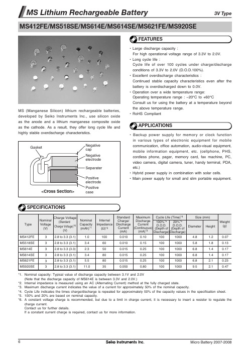
MS614SE,MS518SE,MS621FE,MS920SE-FL27E,MS412FE, 规格书,Datasheet 资料
Gasket
<Cross Section>
Positive case
SPECIFICATIONS
Charge Voltage Nominal (Standard Voltage Charge Voltage)*6 (V) (V) 3 3 3 3 3 3 2.8 to 3.3 (3.1) 2.8 to 3.3 (3.1) 2.8 to 3.3 (3.3) 2.8 to 3.3 (3.1) 2.8 to 3.3 (3.1) 2.8 to 3.3 (3.1) Nominal Capacity (mAh)*1 1.0 3.4 2.3 3.4 5.5 11.0 Internal Impedance (Ω)*2 100 60 50 80 80 35 Cycle Life (Time)*4 Size (mm) Standard Maximum Charge/ Discharge 100%*5 20%*5 Discharge Current D.O.D. D.O.D. Current (Continuous) (Depth of (Depth of Diameter Height *3 (mA) (mA) Discharge) Discharge) 0.010 0.010 0.015 0.015 0.015 0.050 0.10 0.15 0.25 0.25 0.25 0.80 100 100 100 100 100 100 1000 1000 1000 1000 1000 1000 4.8 5.8 6.8 6.8 6.8 9.5 1.2 1.8 1.4 1.4 2.1 2.1 Weight (g) 0.07 0.13 0.17 0.17 0.23 0.47
ISL6558EVAL2;中文规格书,Datasheet资料

IN4728A_datasheet
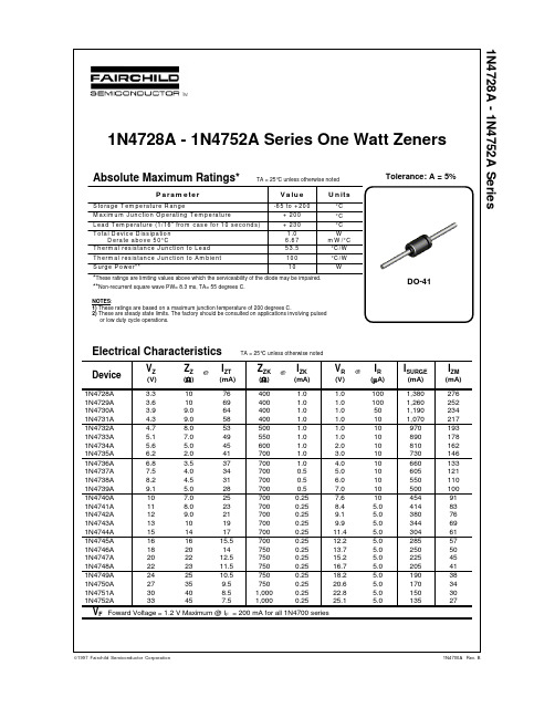
1N4728A - 1N4752A SeriesDO-41©1997 Fairchild Semiconductor Corporation1N4700A Rev. BTRADEMARKSACEx™CoolFET™CROSSVOLT™E 2CMOS TM FACT™FACT Quiet Series™FAST ®FASTr™GTO™HiSeC™The following are registered and unregistered trademarks Fairchild Semiconductor owns or is authorized to use and is not intended to be an exhaustive list of all such trademarks.LIFE SUPPORT POLICYFAIRCHILD’S PRODUCTS ARE NOT AUTHORIZED FOR USE AS CRITICAL COMPONENTS IN LIFE SUPPORTDEVICES OR SYSTEMS WITHOUT THE EXPRESS WRITTEN APPROV AL OF FAIRCHILD SEMICONDUCTOR CORPORA TION.As used herein:ISOPLANAR™MICROWIRE™POP™PowerTrench™QS™Quiet Series™SuperSOT™-3SuperSOT™-6SuperSOT™-8TinyLogic™1. Life support devices or systems are devices or systems which, (a) are intended for surgical implant intothe body, or (b) support or sustain life, or (c) whosefailure to perform when properly used in accordancewith instructions for use provided in the labeling, can be reasonably expected to result in significant injury to the user.2. A critical component is any component of a lifesupport device or system whose failure to perform can be reasonably expected to cause the failure of the life support device or system, or to affect its safety or effectiveness.PRODUCT STATUS DEFINITIONS Definition of TermsDatasheet Identification Product Status Definition Advance InformationPreliminary No Identification Needed Obsolete This datasheet contains the design specifications for product development. Specifications may change in any manner without notice.This datasheet contains preliminary data, andsupplementary data will be published at a later date.Fairchild Semiconductor reserves the right to make changes at any time without notice in order to improve design.This datasheet contains final specifications. Fairchild Semiconductor reserves the right to make changes at any time without notice in order to improve design.This datasheet contains specifications on a product that has been discontinued by Fairchild semiconductor.The datasheet is printed for reference information only.Formative or In DesignFirst ProductionFull ProductionNot In ProductionDISCLAIMERFAIRCHILD SEMICONDUCTOR RESERVES THE RIGHT TO MAKE CHANGES WITHOUT FURTHER NOTICE TO ANY PRODUCTS HEREIN TO IMPROVE RELIABILITY , FUNCTION OR DESIGN. FAIRCHILD DOES NOT ASSUME ANY LIABILITY ARISING OUT OF THE APPLICATION OR USE OF ANY PRODUCT OR CIRCUIT DESCRIBED HEREIN; NEITHER DOES IT CONVEY ANY LICENSE UNDER ITS PATENT RIGHTS, NOR THE RIGHTS OF OTHERS.。
8F5E2 Datasheet说明书
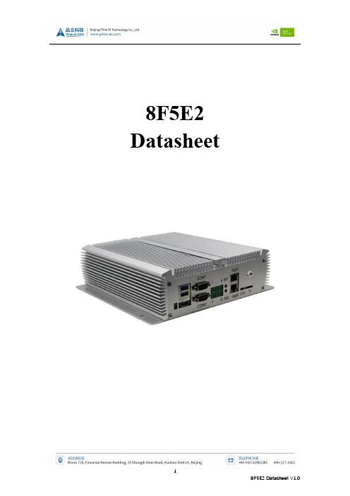
8F5E2 DatasheetDocument HistoryContentsDocument History (2)Preface (4)Disclaimer (4)Customer Support Overview (4)ESD Warning (5)Precautions (6)Limited Product Warranty (6)Introduction (7)Product Features and Specifications (8)Interface function description (11)Typical Installation (13)Recovery Mode (13)Order Information (14)Mechanical Dimensions (15)PrefaceDisclaimerThe information contained within this user’s guide, including but not limited to any product specification, is subject to change without notice.Plink assumes no liability for any damages incurred directly or indirectly from any technical or typographical errors or omissions contained herein or for discrepancies between the product and the user’s guide.Customer Support OverviewIf you experience any difficulties after using the product, please freely contact us directly. Our tech can help you with product installation and difficulties.Our support section is available 24 hours a day, 7 days a week on our website at: /en/Jetson.html. Our technical support is always free.ESD WarningElectronic components and circuits are very sensitive to electrostatic discharge. Although the company will do anti-static protection design for the main interface on the circuit board when designing circuit board products, it is difficult to do anti-static safety protection for all components and circuits. Therefore, it is recommended to follow ESD safety precautions when handling any circuit board component.ESD protection measures include but are not limited to the following:- During transportation or storage, place the card in an ESD bag and do not take it out until installation.- Release the static electricity before touching the board. Using a discharge grounding wrist strap.- Operate the circuit board only in electrostatic discharge safety area.- Avoiding move circuit boards in carpeted areas.- Avoiding contact with components, try to handle the board by the edges.Precautions- Before using the product, please read this manual carefully and keep it properly for future reference- Please pay attention to and follow all warnings and guidelines marked on the product- Please use the matching power adapter to ensure the stability of current and voltage - Please use this product in a cool, dry and clean place- Do not use this product in the environment of alternating cold and heat to avoid condensation and damage to internal components- Do not splash any liquid on the product. It is forbidden to use organic solvent or corrosive liquid to clean the product- Do not use this product in dusty and messy environment. If it is not used for a long time, please pack the product- Do not use it in an environment with excessive vibration. Any falling or knocking may damage the lines and components- Do not plug and unplug the core board and peripheral modules when the power is on- Do not repair or disassemble the product by yourself. If the product fails, contact the company for repair in time- Do not modify or use unauthorized accessories by yourself, and the resulting damage will not be covered by warrantyLimited Product Warranty- Warranty period -Bottom plate and core plate: 3 years (non-human damage)- Contact informationContacts: RMAAddress: Room 718, Jinrongkemao Plaza, No. 15 Shangdi Xinxi Road, Haidian District, Beijing, ChinaE-mail: sales@Telephone:+86-010-********- Mailing instructions: Please contact the sale staff of the company in advance, then arrange technicians to verify and eliminate the errors caused by misoperation as soon as possible. After verification, please mail the equipment to the company.Please attach a list of items and the reason for failure when mailing for easy verification, so as to avoid loss and damage in the process of express delivery.Introduction8F5E2 is a IPC with NVIDIA® Jetson™ AGX Xavier and AGX ORIN 32GB core modules. The main interface is designed for electrostatic safety protection, and a high-reliability power supply application scheme is adopted. The input power supply has over voltage and reverse polarity protection functions, and has a wealth of external interfaces. The internal interface devices are all wide-temperature models.8F5E2 provides multiple independent Gigabit network ports through internal M.2 ports, miniPCIe ports, which is suitable for multi-network port scenarios.8F5E2 is designed based on worse environmental conditions and has good characteristics such as anti-seismic and dust-proof, and is suitable for V2X and other fields.Product Features and Specifications- Product size:198mm×197mm×45 mm- Power requirements:+12V- Working temperature:-25~+70℃- Weight:1340g- Optional expansion:32GB ~ 1TB SSD storage- Maximum scalability 512g TF card memory- 4G and WIFI module can be extended- The initial setting can be reset and restored*Remark:when this model is equipped with AGX Xavier module, only one USB Type A supports USB3.0, Supports only one M.2Key M connector and one miniPCIe connectorPanel and interface IDSFigure 1 Ports on the front panelFigure 2 Ports on the rear panel*There is no interface on the rear panel of the standard machine. The four network interfaces on the rear panel are optional. If you need to use them, please contact the sales staff in advance.Interface function descriptionTypical Installation- Ensure power off of all external system- Install the necessary external cables.(e.g. display cable connected to HDMI monitor, power input cable supplying power to the system, USB cable connecting keyboard and mouse...)- Connect the power cord to the power supply- 8F5E2 could be set as default automatic power on or switch on. Please consult the sales and technical staff of our company for specific methods.Recovery ModeJetson core module can work in normal mode and recovery mode. It can be operated in recovery mode to file system update, kernel update, boot loader update, BCT update and other operationsStep in Recovery mode:- Turn off the system power supply- Use a Micro-USB cable to connect OTG port of the 8F5E2 with USB of the Jetson developing host- Press and hold on Recovery button (REC) to supply system power. Keep REC button for 3seconds above, then release the recovery buttonThe system enters the Recovery mode, and you can perform subsequent operations.Order InformationE-commerce direct purchaseTaobao:https:///Jingdong:https:///index-11467104.html?from=pc Alibaba:https:///Mechanical Dimensions。
SILICON SM5812 5852 Datasheet

SILICONMICROSTRUCTURES I N C O R P O R A T E DSM5812/SM5852Amplified Pressure Sensor• N OW WITH ACCESS TO D IGITAL T EMPERATURE AND C ORRECTED D IGITAL P RESSURE • L OW -COST , FULLY AMPLIFIED , CALIBRATED , AND COMPENSATED IN A SINGLE PACKAGE• A VAILABLE FOR D IFFERENTIAL , S INGLE -ENDED DIFFERENTIAL , G AGE & A BSOLUTE APPLICATIONS •M ULTIPLE PRESSURE RANGES AVAILABLE TO MEASURE PRESSURE DOWN TO 0.15 PSI FULL -SCALEAND UP TO 100 PSI FULL -SCALEDESCRIPTIONThe Silicon Microstructures SM5812 and SM5852 series of OEM pressure sensors combines state-of-the-art pressure sensor technology with CMOS digital signal processing technology to produce an amplified, fully conditioned, multi-order pressure and temperature compensated sensor in a dual in-line package (DIP) configuration.Combining the pressure sensor with acustom signal conditioning ASIC in a single package simplifies the use of advanced silicon micromachined pressure sensors. Now, the pressure sensor can be mounted directly to a standard printed circuit board and an amplified, high level, calibrated pressure signal can be acquired from the digital interface or analog output. This eliminates the need of additional circuitry, such as a compensation network or micro-controller containing a custom correction algorithm.The SM5812/SM5852 Series pressure sensors are based on SMI's highly stable, piezoresistive pressure sensor chips mounted on a ceramic substrate. An electronically programmable ASIC iscontained in the same package to provide calibration and temperature compensation.The model SM5812 is designed foroperating pressure ranges from 0-5 PSI up to 0-100 PSI. The model SM5852 isdesigned for operating pressure ranges from 0-0.15 PSI up to 0-3 PSI. For both models, the sensor output is ratiometric with the supply voltage.FEATURES• Amplified, calibrated, fully signalconditioned output span of 4.0 VDC FS (0.5 to 4.5 V signal)• Digital temperature and calibratedpressure available through I 2C interface • Output ratiometric with supply voltage • Multi-order correction for pressure non-linearity (factory programmed)• Multi-order correction for temperature coefficient of span and offset (factory programmed)• Gage, differential, and absolute versions •SMI’s unique low-pressure die allows for a full-scale pressure range of 0-0.15 PSITYPICAL APPLICATIONS• Barometric measurement • Medical instrumentation • Pneumatic control • Gas flow• Respirators and ventilators•Heating, Ventilation and Air Conditioning (HVAC)查询SM5812-005-A-3-L供应商SM5812/SM5852THEORY OF OPERATIONThe operation of the signal processor is depicted in the block diagram below. The external pressure sensor is a piezoresistive bridge. This transduces the applied pressure into an electronic signal, which is then inputted into the integrating amplifier of the ASIC. During the amplification step an offset correction factor is added in order to allow maximum gain for a given pressure while minimizing the offset error.The signal is then passed to an 11-bit analog to digital converter (ADC). The ADC samples the signal multiple times and uses the sum of those samples as a 13-bit word.A digital signal processor (DSP) is then used to correct and calibrate the pressure signal. The DSP provides multi-order correction of both pressure and temperature non-linearity through the use of factory-programmed coefficients. A combined total of twenty coefficients are available for correcting pressure and temperature non-linearity. The unique coefficients are determined during a calibration process performed at the factory. Factory calibration is the last step performed which means the effect of the package on the pressure signal will also be taken into account. This provides a great advantage over conventional laser-trimming approaches.The DSP outputs a corrected digital word, which travels to a 12-bit digital to analog converter (DAC) to provide a calibrated analog output. In addition to the analog output, the corrected pressure signal is accessible through an I2C digital interface. See SMI application note AN05-001 for a detailed description of how to read out the digital corrected pressure signal using theI2C bus interface.Analog OutputSDA SCLSILICONMICROSTRUCTURES I N C O R P O R A T E DSM5812/SM5852CHARACTERISTICS FOR SM5812/SM5852 – SPECIFICATIONSAll parameters are measured at room temperature while applying 5.000V supply, unless otherwise specified.Absolute 1, Gage & Single 2DifferentialMIN TYP MAX MIN TYP MAX UNITS NOTES Zero output (absolute and gauge) 0.42 0.50 0.58 V 3 Zero output (differential)2.422.502.58V3Output Span3.924.00 4.08 1.96 2.00 2.04 V FS 3, 40.15 PSI 3.80 4.00 4.20 1.90 2.00 2.10 V FS 3, 4 Linearity -0.5 +0.5 -0.5 +0.5 %FS 5 0.15 PSI-2.5+2.5-2.5+2.5%FS5 Pressure hysteresis 5812 -0.1 +0.1 -0.1 +0.1 %FS5852 -0.3+0.3 -0.3 +0.3 %FS Temperature coefficient - Zero-1.0 +1.0 -1.0 +1.0 %FS 0.15 PSI-2.5 +2.5 -2.5 +2.5 %FS Temperature coefficient – Span-1.0 +1.0 -1.0 +1.0 %FS 0.15 PSI-2.0 +2.0 -2.0 +2.0 %FS Thermal hysteresis -0.1 +0.1 -0.1 +0.1 %FS Response Time 2 2 msec Supply voltage 4.75 5.00 5.25 4.75 5.00 5.25 V 3, 7Current consumption10 10 mAOverpressure 5812 3X 3X %FS 65852 15X15X %FS 6 Operating temperature range -40 25 +125 -40 25 +125 °C Compensated temperature range 0 25 +70 0 25 +70 °CStorage temperature range -5525+135-5525+135°CMedia compatibility 8Weight 3 3 gramNotes: 1. Absolute parts are only offered in the SM5812 Series.2. Single-ended parts (Pressure Type - S) have 2 ports and are for higher gain differential applications where the differential pressure is always positive.3. Sensor output is ratiometric to supply.4.Full-scale (FS) is defined as zero pressure to rated pressure; differential parts can be used ±FS. Absolute and Gauge zero output is 0.5 V typical and full-scale output is 4.5 V. Span is the difference between Full-scale output and zero output, (4 V). For Differential parts, the negative full-scale is typically at 0.5 V, zero is typically 2.5 V, and positive full-scale is 4.5 volts to give a span of ±2.0 V.5. Defined as best fit straight line for positive pressure applied to the part6. Or 225 PSI, whichever is less. Output amplifier will saturate at about 0.25 V for applied pressure below the rated Zero and at about 4.75 V for applied pressure above the rated Full-scale.7. A 100 nF filter capacitor must be placed between Vsupply and Ground.8.Clean, dry gas compatible with wetted materials. Wetted materials include Pyrex glass, silicon, alumina ceramic, epoxy, RTV, gold, aluminum, and nickel.SM5812/SM5852ADDITIONAL INFORMATIONFull-Scale Pressure RangesSM5812 PSI [kPa] SM5852 PSI [kPa]005 5 [34.5] 001 0.15 [1.0] 015 15 [103.4]003 0.30 [2.1] 030 30 [206.8]008 0.80 [5.5] 060 60 [413.7]015 1.50 [10.3] 100 100[689.5]030 3.00 [20.7]。
- 1、下载文档前请自行甄别文档内容的完整性,平台不提供额外的编辑、内容补充、找答案等附加服务。
- 2、"仅部分预览"的文档,不可在线预览部分如存在完整性等问题,可反馈申请退款(可完整预览的文档不适用该条件!)。
- 3、如文档侵犯您的权益,请联系客服反馈,我们会尽快为您处理(人工客服工作时间:9:00-18:30)。
CC1 EA_OUT1 TRI_0 VS
CBOOT VBOOT
CHARGE PUMP VR + INPUT & SENSE AMP -
+ + -
ERROR AMP TRI_180
C POWER BRIDGE 1
OUT1A
VREF1 I3_1 I2_1 I1_1 I0_1 PH_1 VDD(5V) DAC
C
OUT1B SENSE1B Rs
SENSE1A VR GEN VR (VDD/2) THERMAL PROT. DISABLE VS
VREF1 I3_2 I2_2 I1_2 I0_2 PH_2 TRI_CAP CFREF TRIANGLE GENERATOR TRI_0 TRI_180 DAC VR INPUT & SENSE AMP + -
Note: The number in parenthesis shows the relevant Power Bridge of the circuit. Pins 18, 19, 1 and 36 are connected together.
3/24
L6258E
Figure 4. Thermal Characteristics
ERROR AMP
TRI_0
+ +
C POWER BRIDGE 2
OUT2A
TRI_180
-
C
OUT2B SENSE2B Rs
SENSE2A
GND
EA_IN2 RC2 R2 1M
EA_OUT2
D96IN430D
CC2
Hale Waihona Puke September 2004
Rev. 7 1/24
L6258E
Table 2. Absolute Maximum Ratings
Symbol Vs VDD Vref1/Vref2 IO IO Vin Vboot Vboot - Vs Tj Tstg Supply Voltage Logic Supply Voltage Reference Voltage Output Current (peak) Output Current (continuous) Logic Input Voltage Range Bootstrap Supply Maximum Vgate applicable Junction Temperature Storage Temperature Range Parameter Value 45 7 2.5 1.5 1.2 -0.3 to 7 60 15 150 -55 to 150 Unit V V V A A V V V °C °C
Figure 1. Package
■
PowerSO36
■ ■
Table 1. Order Codes
Part Number L6258E (Replaced by L6258EX) Package PowerSO36
■ ■ ■ ■ ■
2
DESCRIPTION
L6258E is a dual full bridge for motor control applications realized in BCD technology, with the capability of driving both windings of a bipolar stepper motor or bidirectionally control two DC motors. L6258E and a few external components form a comFigure 2. Block Diagram
L6258E
PWM CONTROLLED - HIGH CURRENT DMOS UNIVERSAL MOTOR DRIVER
NOT FOR NEW DESIGN
1
■
FEATURES
ABLE TO DRIVE BOTH WINDINGS OF A BIPOLAR STEPPER MOTOR OR TWO DC MOTORS OUTPUT CURRENT UP TO 1.2A EACH WINDING WIDE VOLTAGE RANGE: 12V TO 40V FOUR QUADRANT CURRENT CONTROL, IDEAL FOR MICROSTEPPING AND DC MOTOR CONTROL PRECISION PWM CONTROL NO NEED FOR RECIRCULATION DIODES TTL/CMOS COMPATIBLE INPUTS CROSS CONDUCTION PROTECTION THERMAL SHUTDOW
R1 1M RC1 CP VCP1 VCP2 EA_IN1
plete control and drive circuit. It has high efficiency phase shift chopping that allows a very low current ripple at the lowest current control levels, and makes this device ideal for steppers as well as for DC motors.The power stage is a dual DMOS full bridge capable of sustaining up to 40V, and includes the diodes for current recirculation.The output current capability is 1.2A per winding in continuous mode, with peak start-up current up to 1.5A. A thermal protection circuitry disables the outputs if the chip temperature exceeds the safe limits.
D96IN432E
36 35 34 33 32 31 30 29 28 27 26 25 24 23 22 21 20 19
PWR_GND SENSE1 OUT1B I3_1 I2_1 VS EA_OUT1 EA_IN1 VREF1 SIG_GND VREF2 EA_IN2 EA_OUT2 I2_2 I3_2 OUT2B SENSE2 PWR_GND
Figure 3. Pin Connection (Top view)
PWR_GND PH_1 I1_1 I0_1 OUT1A DISABLE TRI_CAP VDD GND VCP1 VCP2 VBOOT VS OUT2A I0_2 I1_2 PH_2 PWR_GND
1 2 3 4 5 6 7 8 9 10 11 12 13 14 15 16 17 18
Conditions
Power Dissipated T Ambient Thermal J-A resistance (W) (˚C) (˚C/W)
2/24
L6258E
Table 3. Pins Function
Pin # 1, 36 2, 17 3 4 5 6 7 8 9 10 11 12 13, 31 14 15 16 18, 19 20, 35 21 22 23 24 25 26, 28 27 29 30 32 33 34 Name PWR_GND PH_1, PH_2 I1_1 I0_1 OUT1A DISABLE TRI_cap VDD (5V) GND VCP1 VCP2 VBOOT VS OUT2A I0_2 I1_2 PWR_GND SENSE2, SENSE1 OUT2B I3_2 I2_2 EA_OUT_2 EA_IN_2 VREF2, VREF1 SIG_GND EA_IN_1 EA_OUT_1 I2_1 I3_1 OUT1B Description Ground connection (1). They also conduct heat from die to printed circuit copper. These TTL compatible logic inputs set the direction of current flow through the load. A high level causes current to flow from OUTPUT A to OUTPUT B. Logic input of the internal DAC (1). The output voltage of the DAC is a percentage of the Vref voltage applied according to the thruth table of page 7 See pin 3 Bridge output connection (1) Disables the bridges for additional safety during switching. When not connected the bridges are enabled Triangular wave generation circuit capacitor. The value of this capacitor defines the output switching frequency Supply Voltage Input for logic circuitry Power Ground connection of the internal charge pump circuit Charge pump oscillator output Input for external charge pump capacitor Overvoltage input for driving of the upper DMOS Supply voltage input for output stage. They are shorted internally Bridge output connection (2) Logic input of the internal DAC (2). The output voltage of the DAC is a percentage of the VRef voltage applied according to the truth table of page 7 See pin 15 Ground connection. They also conduct heat from die to printed circuit copper Negative input of the transconductance input amplifier (2, 1) Bridge output connection and positive input of the tranconductance (2) See pin 15 See pin 15 Error amplifier output (2) Negative input of error amplifier (2) Reference voltages for the internal DACs, determining the output current value. Output current also depends on the logic inputs of the DAC and on the sensing resistor value Signal ground connection Negative input of error amplifier (1) Error amplifier output (1) See pin 3 See pin 3 Bridge output connection and positive input of the tranconductance (1)
