WRT160Nv2中文手册
Bulletin 160 SSC Remote Keypad FRN 1.x 用户手册说明书
Important User InformationSolid-State equipment has operational characteristics differing from those ofelectromechanical equipment. “Safety Guidelines for the Application, Installationand Maintenance of Solid-State Controls” (Publication SGI-1.1) describes someimportant differences between solid-state equipment and hard-wiredelectromechanical devices. Because of this difference, and also because of the widevariety of uses for solid-state equipment, all persons responsible for applying thisequipment must satisfy themselves that each intended application of this equipmentis acceptable.In no event will Rockwell Automation be responsible or liable for indirect orconsequential damages resulting from the use or application of this equipment.The examples and diagrams in this manual are included solely for illustrativepurposes. Because of the many variables and requirements associated with anyparticular installation, Rockwell Automation cannot assume responsibility orliability for actual use based on the examples and diagrams.No patent liability is assumed by Rockwell Automation with respect to use ofinformation, circuits, equipment, or software described in this manual.Reproduction of the contents of this manual, in whole or in part, without writtenpermission of Rockwell Automation is prohibited.Throughout this manual we use notes to make you aware of safety considerations:SSC is a trademark of Rockwell Automation, Inc.Table of Contents IntroductionDrive Compatibility . . . . . . . . . . . . . . . . . . . . . . . . . . . . . . . . . . . . . . . . . . . . . . . . . . . . . . . . . . . . . . .1-1Related Publications . . . . . . . . . . . . . . . . . . . . . . . . . . . . . . . . . . . . . . . . . . . . . . . . . . . . . . . . . . . . . .1-1Remote Programming Adapter . . . . . . . . . . . . . . . . . . . . . . . . . . . . . . . . . . . . . . . . . . . . . . . . . . . . . .1-2 Removal and Installation . . . . . . . . . . . . . . . . . . . . . . . . . . . . . . . . . . . . . . . . . . . . . . . . . . .1-2Grounding . . . . . . . . . . . . . . . . . . . . . . . . . . . . . . . . . . . . . . . . . . . . . . . . . . . . . . . . . . . . . .1-3 Connector Cable . . . . . . . . . . . . . . . . . . . . . . . . . . . . . . . . . . . . . . . . . . . . . . . . . . . . . . . . . . . . . . . . .1-4Features . . . . . . . . . . . . . . . . . . . . . . . . . . . . . . . . . . . . . . . . . . . . . . . . . . . . . . . . . . . . . . . . . . . . . . .1-5Display Description . . . . . . . . . . . . . . . . . . . . . . . . . . . . . . . . . . . . . . . . . . . . . . . . . . . . . . . . . . . . . . .1-6Drive Status Indicators . . . . . . . . . . . . . . . . . . . . . . . . . . . . . . . . . . . . . . . . . . . . . . . . . . . . . . . . . . . .1-6Keypad Initialization Sequence . . . . . . . . . . . . . . . . . . . . . . . . . . . . . . . . . . . . . . . . . . . . . . . . . . . . . .1-7 InstallationPrepare Mounting Location . . . . . . . . . . . . . . . . . . . . . . . . . . . . . . . . . . . . . . . . . . . . . . . . . . . . . . . . .2-1Mount the Remote Keypad . . . . . . . . . . . . . . . . . . . . . . . . . . . . . . . . . . . . . . . . . . . . . . . . . . . . . . . . .2-2 Control the DriveEnable Keypad Control to Start the Drive . . . . . . . . . . . . . . . . . . . . . . . . . . . . . . . . . . . . . . . . . . . . . .3-1Save Changes to Parameter 46 . . . . . . . . . . . . . . . . . . . . . . . . . . . . . . . . . . . . . . . . . . . . . . . . . . . . .3-1Stop the Drive . . . . . . . . . . . . . . . . . . . . . . . . . . . . . . . . . . . . . . . . . . . . . . . . . . . . . . . . . . . . . . . . . . .3-2Change Direction of Motor Rotation . . . . . . . . . . . . . . . . . . . . . . . . . . . . . . . . . . . . . . . . . . . . . . . . . .3-2 TroubleshootingHow to Clear a Fault . . . . . . . . . . . . . . . . . . . . . . . . . . . . . . . . . . . . . . . . . . . . . . . . . . . . . . . . . . . . . .4-1Resolving Problems . . . . . . . . . . . . . . . . . . . . . . . . . . . . . . . . . . . . . . . . . . . . . . . . . . . . . . . . . . . . . .4-2 Technical SpecificationsDimensions . . . . . . . . . . . . . . . . . . . . . . . . . . . . . . . . . . . . . . . . . . . . . . . . . . . . . . . . . . . . . . . . . . . . .A-1 Ambient Conditions . . . . . . . . . . . . . . . . . . . . . . . . . . . . . . . . . . . . . . . . . . . . . . . . . . . . . . . . . . . . . . .A-1 Input/Output Ratings . . . . . . . . . . . . . . . . . . . . . . . . . . . . . . . . . . . . . . . . . . . . . . . . . . . . . . . . . . . . . .A-1 Approvals and Standards Compliance . . . . . . . . . . . . . . . . . . . . . . . . . . . . . . . . . . . . . . . . . . . . . . . .A-1 Maintenance . . . . . . . . . . . . . . . . . . . . . . . . . . . . . . . . . . . . . . . . . . . . . . . . . . . . . . . . . . . . . . . . . . . .A-2iiChapter 1Introduction The Remote Keypad can be used to change drive parameter values, monitoroperating conditions, and control drive operation.Important:The four-character Remote Keypad display requires an extrakeystroke in order to display a current parameter value. See feature4 on page 1-5 and step 4 on page 3-1.Remote Keypad Figure 1.1Drive CompatibilityThe Remote Keypad is compatible with Bulletin 160 SSC™ Variable Speed SeriesC drives using firmware version FRN 7.01 or higher.Related PublicationsPrior to using the Remote Keypad, please familiarize yourself with the followingpublications for complete parameter and fault descriptions and detailedinformation about hazards associated with AC drives.•160 SSC™ Variable Speed Drive (Series C) User Manual,Publication 0160-5.15•160 SSC™ Variable Speed Drive Quick Reference Series C,Publication 0160-5.161-2IntroductionRemote Programming AdapterThe Remote Programming Adapter (160-RPA) allows the Remote Keypad tointerface with a Bulletin 160 Series C drive.If your drive is equiped with a Ready/Fault Indicating Panel (160-B1) or a ProgramKeypad Module (160-P1), you must remove these modules and install a RemoteProgramming Adapter in order to use the Remote Keypad.Removal and InstallationInsert a small screw driver into the slot at top of panel/keypad. Carefully pry backand pivot the module out. Avoid bending or twisting the contact pins locatedunderneath the center portion of the module.Insert the RPA module, bottom first, into the drive. Press down on the top cornersof the module until it is firmly seated.Module Removal and Adapter Installation Figure 1.2Introduction1-3 GroundingIt is required that the Remote Programming Adapter be earth grounded to improvenoise immunity and to guard the Remote Keypad against hazardous DC buspotential voltages.1-4IntroductionConnector CableA cable is used to connect the Remote Keypad to the Bulletin 160 Series C drive.The Keypad can be connected and disconnected when the drive is under power.Important:If P46 - [Input Mode] is set to 2 or 6, disconnecting the RemoteKeypad will cause the drive to fault.The following connector cables are available and purchased separately.•160-C10 – 1 meter cable, non-locking•160-C10R – 1 meter cable, non-locking with right angle for minimal depth•160-C30 – 3 meter cable, locking each end•160-C50 – 5 meter cable, locking each endThe 3- and 5-meter connector cables have a locking mechanism to ensure that thecable will not be disconnected accidentally. The 1-meter connector cables do nothave a locking mechanism. To remove the cable from the drive or the RemoteKeypad, pull back on the plastic housing of the cable connector.Introduction 1-5FeaturesThe figure and table below identify and describe the Remote Keypad display, status indicators, and keys.Remote Keypad Features Figure 1.6 FeatureDescription 1Display Four 7-segment light emitting diodes (LEDs)2Indicator LEDs Four LEDs indicate mode of operation.3Escape Key •Press to toggle between Display mode and Program mode.•In Edit mode, press to cancel an edit sequence and return to Programmode.4Enter Key •In Display or Program modes, press to toggle between parameter numbersand values.•In Edit mode, press to save a new parameter value.5Select Key In Program mode with a parameter value displayed, press to enter Edit mode.Use the Up or Down arrow keys to change the parameter value.6Up and Down Arrow Keys •In Program mode, use to scroll Program Group parameter numbers orchange a parameter value.•In Display mode, use to scroll Display Group parameters numbers.7Reverse Key Changes direction of motor rotation when keypad control is selected(P46 = 2 or 6) and reverse is enabled (P73 = 0)8Start Key Issues a start command to drive when keypad control is selected(P46 = 2 or 6).9Stop Key •Issues a stop command to drive.•Press to reset a fault after taking corrective action.1-6 IntroductionDisplay DescriptionThe keypad has a four-character LED display which shows parameter numbers, parameter values, and fault codes. The keypad monitors its connection to the drive. If this connection fails due to electrical noise or a hardware failure, the following is displayed.If the drive faults, the display will flash indicating the presence of the fault, and the fault code will be displayed. Pressing the Up or Down arrow, Enter, or Escape key will return the keypad to Display mode. If the fault condition is reset without pressing one of these keys, the display will return to the display or program parameter that was selected prior to the occurrence of the fault.Drive Status IndicatorsThe keypad has four status LEDs which serve as mode and direction indicators.LED FunctionsT able 1.B NameStatus DescriptionPROGRAM OnThe keypad is in Program mode.OffThe keypad is in Display mode.FlashingThe keypad is in Edit mode.RUNOn The drive is running.FORWARDOn If keypad control is selected (P46 = 2 or 6), this LED will turn onif the direction commanded by the keypad is forward.If keypad control is not selected, this LED will turn on when thedrive is running forward.Flashing The FORWARD LED will flash when the drive is commanded tochange direction from forward to reverse and will stop flashingwhen the motor decelerates to zero. The REVERSE LED willilluminate indicating the commanded direction.REVERSE On If keypad control is selected (P46 = 2 or 6), this LED will turn onif the direction commanded by the keypad is reverse.If keypad control is not selected, this LED will turn on when thedrive is running reverse.Flashing The REVERSE LED will flash when the drive is commanded tochange direction from reverse to forward and will stop flashingwhen the motor decelerates to zero. The FORWARD LED willilluminate indicating the commanded direction.Introduction1-7 Keypad Initialization SequenceWhen the Remote Keypad is connected to the drive, and power is applied, thefollowing is displayed for approximately two seconds.After two seconds have elapsed, the keypad will display the current value of thelast Display Group parameter selected. In this example, P01 - [Output Frequency] isat 0.0 Hertz.1-8Introduction End of ChapterChapter 2InstallationPrepare Mounting Location•Select a mounting location that is less than 5 meters away from the drive.Connection cables are available in 1, 3, and 5 meter lengths.•Install in a suitable IP55 or IP65 rated enclosure.Drilling Pattern and Dimensions Figure 2.12-2InstallationMount the Remote KeypadInstallation and T orque Sequence Figure 2.2Chapter 3Control the Drive Enable Keypad Control to Start the DriveThe following steps also serve as a programming example.1.With the Remote Keypad installed and connected to the Bulletin 160 Series Cdrive, power up the drive.The Remote Keypad always powers up in the Display mode. While in thismode you may view all read only drive parameters, but not modify them.2.Press the Escape key to enter the Program mode.The Program LED will light and Parameter 30 is displayed.e the Up or Down arrow key to scroll to P46 - [Input Mode].4.Press the Enter key to display the parameter value.5.Press the Select key to enter the Edit mode.The Program LED will flash indicating that the parameter value may bechanged.6.Change P46 - [Input Mode] to 2 or 6 using the Up or Down arrow key.7.Press the Enter key to save the new value.The Program LED will stop flashing and remain lit.Important:When P46 - [Input Mode] is set to 2 or 6, disconnecting the RemoteKeypad will cause the drive to fault.Save Changes to Parameter 46In order for changes to P46 - [Input Mode] to take effect, cycle power or setP56 - [Reset Functions] to 2.e the Up or Down arrow key to scroll to P56 - [Reset Functions].2.Press the Enter key to display the default parameter value of 0.3.Press the Select key to enter the Edit mode.4.Change P56 - [Reset Functions] to 2 using the Up or Down arrow key.5.Press the Enter key to save the new value.The new P46 - [Input Mode] value is saved and P56 - [Reset Functions] resets to 0.You can now use the Remote Keypad to start the drive.Important:The Stop/Reset digital input on the drive (TB3-8) must bemaintained in the ON state for the keypad to start the drive.3-2Control the DriveStop the DriveUse the Stop key to command the drive to stop. The Stop key functions in all driveinput modes whether or not the keypad is selected as the drive’s control source.Change Direction of Motor RotationOnce the Remote Keypad is set to control drive operation (P46 - [Input Mode] is setto 2 or 6) you can change the direction of motor rotation by pressing the Reverse key.When the motor is running, pressing the Reverse key causes the motor to rampdown to 0 Hz and then ramp up to its set speed in the opposite direction.Chapter 4TroubleshootingHow to Clear a FaultWhen a fault occurs, the cause must be corrected before the fault can be cleared.After corrective action has been taken, any of the following actions will clear thefault.•Press the Remote Keypad Stop button•Set P54 - [Clear Fault] to 1.•Disconnect power to the drive, wait three minutes, reapply power.•Cycle the input signal at TB3-8 to the drive.Please consult the 160 SSC™ Variable Speed Drive (Series C) User Manual,Publication 0160-5.15, for a complete listing of fault descriptions and possibleproblems and corrective actions.4-2Troubleshooting DRAFT – 7/19/99 Resolving ProblemsImportant:The connector cable, RPA, and Keypad are not repairable.Appendix ATechnical Specifications DimensionsAmbient Conditions•Operating temperature: 0˚ C to 50˚ C (32˚ F to 122˚ F)•Storage temperature: -40˚ C to 85˚ C (-40˚ F to 185˚ F)•Relative humidity: 0 to 95%, non-condensing.Input/Output Ratings•Input voltage: 5 VDC (from drive power supply)•Input current: 75 mA (maximum, from drive power supply)Approvals and Standards Compliance•UL508C•CSA 22.2•CE•EN-50178•IP 66 (NEMA Type 12/UL Type 4X Indoor)A-2Technical SpecificationsMaintenanceUse only a soft cloth dampened with water to clean the keypad.The RPA requires no maintenance or cleaning.Publication 0160-5.28ML – September, 1999P/N 194308 (01)Copyright 1999 Rockwell International Corporation. All rights reserved. Printed in USA.。
TL-R1660+ V2详细配置指南

2.2 2.3 2.4
第3章
3.1 3.2 3.3 3.4
配置指南 ........................................................................................................ 4
启动和登录 ...................................................................................................................... 4 运行状态 .......................................................................................................................... 4 设置向导 .......................................................................................................................... 5 网络参数 .......................................................................................................................... 6 3.4.1 LAN 口设置.......................................................................................................... 6 3.4.2 WAN 口设置 ........................................................................................................ 7 3.4.3 MAC 地址克隆 ................................................................................................... 15 DHCP 服务器................................................................................................................. 16 3.5.1 DHCP 服务 ........................................................................................................ 16 3.5.2 客户端列表 ........................................................................................................ 17 3.5.3 静态地址分配 ..................................................................................................... 17 转发规则 ........................................................................................................................ 19 3.6.1 虚拟服务器 ........................................................................................................ 19 3.6.2 特殊应用程序 ..................................................................................................... 21 3.6.3 DMZ 主机 .......................................................................................................... 22 3.6.4 UPnP 设置 ......................................................................................................... 23 安全设置 ........................................................................................................................ 24 3.7.1 防火墙设置 ........................................................................................................ 24 3.7.2 IP 地址过滤........................................................................................................ 25 3.7.3 域名过滤 ............................................................................................................ 27 3.7.4 MAC 地址过滤 ................................................................................................... 28 3.7.5 远端 WEB 管理 .................................................................................................. 29 3.7.6 高级安全设置 ..................................................................................................... 30 路由功能 ........................................................................................................................ 32 3.8.1 静态路由表 ........................................................................................................ 32 IP 带宽控制 .................................................................................................................... 33
Linksys WRT160N无线路由器
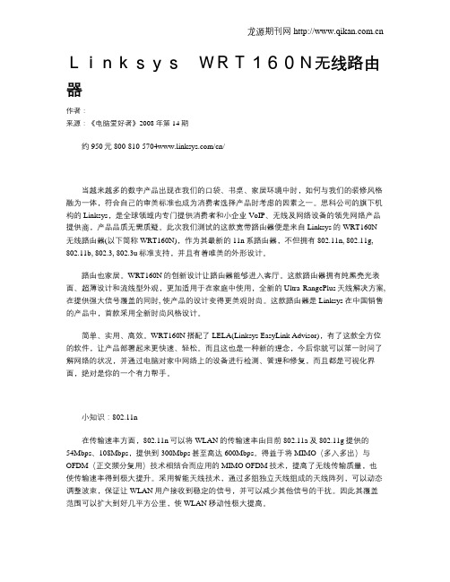
LinksysWRT160N无线路由器作者:来源:《电脑爱好者》2008年第14期约950元/cn/当越来越多的数字产品出现在我们的口袋、书桌、家居环境中时,如何与我们的装修风格融为一体,符合自己的审美标准也成为消费者选择产品时考虑的因素之一。
思科公司的旗下机构的Linksys,是全球领域内专门提供消费者和小企业VoIP、无线及网络设备的领先网络产品提供商,产品品质无需质疑。
此次我们测试的这款宽带路由器便是来自Linksys的WRT160N 无线路由器(以下简称WRT160N),作为其最新的11n系路由器,不但拥有802.11n, 802.11g, 802.11b, 802.3, 802.3u标准支持,并且有着唯美的外形设计。
路由也家居。
WRT160N的创新设计让路由器能够进入客厅。
这款路由器拥有纯黑亮光表面、超薄设计和流线型外观,更加适用于在家庭中使用,全新的Ultra RangePlus天线解决方案,在提供强大信号覆盖的同时, 使产品的设计变得更美观时尚。
这款路由器是Linksys在中国销售的产品中,首款采用全新时尚风格设计。
简单、实用、高效。
WRT160N搭配了LELA(Linksys EasyLink Advisor),有了这款全方位的软件,让产品部署起来更快速、轻松。
而且这也是一种新的理念,今后你就可以第一时间了解网络的状况,并通过电脑对家中网络上的设备进行检测、管理和修复,而且都是可视化界面,绝对是你的一个有力帮手。
小知识:802.11n在传输速率方面,802.11n可以将WLAN的传输速率由目前802.11a及802.11g提供的54Mbps、108Mbps,提供到300Mbps甚至高达600Mbps。
得益于将MIMO(多入多出)与OFDM(正交频分复用)技术相结合而应用的MIMO OFDM技术,提高了无线传输质量,也使传输速率得到极大提升。
采用智能天线技术,通过多组独立天线组成的天线阵列,可以动态调整波束,保证让WLAN用户接收到稳定的信号,并可以减少其他信号的干扰。
路由器 Gigabit 无线 N300 WNR3500Lv2 使用说明书
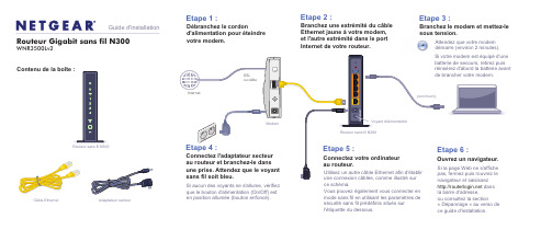
Attendez que votre modem démarre (environ 2 minutes).Si votre modem est équipé d'une batterie de secours, retirez puis réinsérez d'abord la batterie avant de brancher votre modem.Contenu de la boîte :Routeur Gigabit sans fil N300WNR3500Lv2Guide d'installationAdaptateur secteurCâble Ethernet Etape 1 :Débranchez le cordond'alimentation pour éteindre votre modem.Etape 2 :Branchez une extrémité du câble Ethernet jaune à votre modem, et l'autre extrémité dans le port Internet de votre routeur.Branchez le modem et mettez-le sous tension.Etape 3 :Etape 6 :Etape 4 :Connectez l'adaptateur secteur au routeur et branchez-le dans une prise. Attendez que le voyant sans fil soit bleu.Si aucun des voyants ne s'allume, vérifiez que le bouton d'alimentation (On/Off) est en position allumée (bouton enfoncé).Etape 5 :Connectez votre ordinateur au routeur.Utilisez un autre câble Ethernet afin d'établir une connexion câblée, comme illustré sur ce schéma.Vous pouvez également vous connecter en mode sans fil en utilisant les paramètres de sécurité sans fil prédéfinis situés sur l'étiquette du dessous.Ouvrez un navigateur.Si la page Web ne s'affiche pas, fermez puis rouvrez le navigateur et saisissez dans la barre d'adresse, ou consultez la section« Dépannage » au verso de ce guide d'installation.Routeur sans fil N300ModemVoyant d'alimentationInternetDSL ou câbleRouteur sans fil N300(non fourni)NETGEAR, le logo NETGEAR et Connect with Innovation sont des marques commerciales et/ou desmarques déposées de NETGEAR, Inc. et/ou des filiales de NETGEAR aux Etats-Unis et/ou dans d'autres pays. Les informations sont sujettes à changement sans préavis. Les autres marques et noms de produits sont des marques commerciales ou des marques déposées de leurs détenteurs respectifs. © NETGEAR, Inc. Tousdroits réservés.Août 2014Sécurité sans fil prédéfinieCe produit possède un nom de réseau Wi-Fi (SSID) et une clé réseau (mot de passe)uniques. Le SSID et la clé réseau (mot de passe) par défaut sont générés pour chaque périphérique (à l'image d'un numéro de série), afin de protéger et d'optimiser votre sécurité sans fil. Ces informations sont disponibles sur l'étiquette située en dessous du produit.NETGEAR vous recommande de ne pas modifier le nom de réseau Wi-Fi (SSID) et la clé réseau (mot de passe) prédéfinis. Si vous modifiez ces paramètres, les informations indiquées en dessous du produit ne sont plus valables.Identifiez les paramètres de réseau sans fil prédéfinis sur votre routeur et inscrivez-les ici :Wi-Fi Network Name (SSID) (Nom de réseau Wi-Fi [SSID]) _____________ Network Key (Password) (Clé réseau [mot de passe]) _________________Si vous modifiez les paramètres de réseau sans fil prédéfinis, inscrivez les nouveaux paramètres ici :Wireless Network Name (SSID) (Nom de réseau sans fil [SSID]) ___________ Network Key (Password) (Clé réseau [mot de passe]) ___________________Si vous avez besoin de récupérer ou de mettre à jour votre mot de passe, saisissez dans un navigateur Web et connectez-vous en utilisant le nom d'utilisateur par défaut (admin ) et le mot de passe par défaut (password ).Sélectionnez Wireless Settings (Paramètres réseau sans fil) pour localiser votre mot de passe sans fil.Connexion des périphériques sans fil à votre routeurChoisissez la méthode manuelle ou la méthode WPS (Wi-Fi Protected Setup) pour ajouter des ordinateurs portables et divers périphériques à votre réseau sans fil.Méthode manuelle1. Lancez l'utilitaire qui gère vos connexions sans fil sur le périphérique sans filque vous souhaitez connecter à votre routeur (iPhone, ordinateur portable, ordinateur, console de jeu). Cet utilitaire recherche l'ensemble des réseaux sans fil disponibles.2. Recherchez le nom de réseau sans fil (SSID) NETGEAR prédéfini etsélectionnez-le. Le nom de réseau Wi-Fi (SSID) prédéfini est indiqué sur l'étiquette du produit, située en dessous du routeur.Remarque :si vous avez modifié le nom de votre réseau lors du processus d'installation, recherchez ce nouveau nom de réseau.3. Saisissez le mot de passe prédéfini (ou votre mot de passe personnalisé sivous l'avez modifié) et cliquez sur Connect(Connecter).4. Répétez les étapes 1 à 3 pour ajouter des périphériques sans filsupplémentaires.Méthode WPSSi votre périphérique sans fil prend en charge la fonctionnalité WPS (Wi-Fi Protected Setup), que NETGEAR appelle la méthode Push 'N' Connect, il vous sera peut-être demandé d'appuyer sur un bouton WPS situé sur le routeur au lieu de saisir un mot de passe. Le cas échéant :1. Appuyez sur le bouton WPS du routeur.2. Dans un délai de 2 minutes, appuyez sur le bouton WPS situé sur lepériphérique client ou suivez les instructions relatives à la fonctionnalité WPS accompagnant votre périphérique sans fil pour terminer la procédure WPS. Le périphérique est alors connecté à votre routeur.3. Répétez cette procédure pour ajouter des périphériques sans fil WPSsupplémentaires.Remarque :le WPS ne prend pas en charge la sécurité WEP. Si vous tentez de connecter un client WEP à votre réseau à l'aide de la fonctionnalité WPS, cela ne fonctionnera pas.DépannageLe navigateur ne peut pas afficher la page Web.• Assurez-vous que votre PC est connecté au routeur par l'un des quatre ports deréseau local Ethernet ou en mode sans fil.• Vérifiez que le routeur est sous tension et qu'il fonctionne. Son voyant sans fildoit être allumé.• Fermez puis rouvrez le navigateur afin de vérifier que ce dernier ne conservepas la page précédente en mémoire cache.• Accédez à .• Si le PC est configuré avec une adresse IP fixe ou statique (ce qui est rare),modifiez ce paramètre afin d'obtenir automatiquement une adresse IP auprès du routeur.AssistanceMerci d'avoir choisi les produits NETGEAR.Après l'installation de votre périphérique, notez le numéro de série inscrit surl'étiquette de votre produit. Il vous sera nécessaire pour enregistrer votre produit à l'adresse https:// . Vous devez enregistrer votre produit avant de pouvoir utiliser l'assistance téléphonique de NETGEAR. NETGEAR vousrecommande d'enregistrer votre produit sur le site Web de NETGEAR. Pour obtenir des mises à jour de produits et accéder au support Web, rendez-vous à l'adresse . NETGEAR vous recommande d'utiliser uniquement les ressources d'assistance officielles de NETGEAR.Vous pouvez obtenir le manuel de l'utilisateur en ligne à l'adresse ou via un lien dans l'interface utilisateur du produit. Pour consulter la déclaration de conformité actuelle pour l'UE rendez-vous sur le site /app/answers/detail/a_id/11621/. Pour obtenir les informations relatives à la conformité légale, visitez la page/about/regulatory/. Avant de brancher l'alimentation, reportez-vous au document de conformité légale.Obtenez l'application genie.Téléchargez gratuitement l'assistant genie à l'adresse /genie . Partagez des contenus multimédias, des fichiers et des imprimantes sur le réseau à partir de votre smartphone, votre tablette ou votre ordinateur portable.。
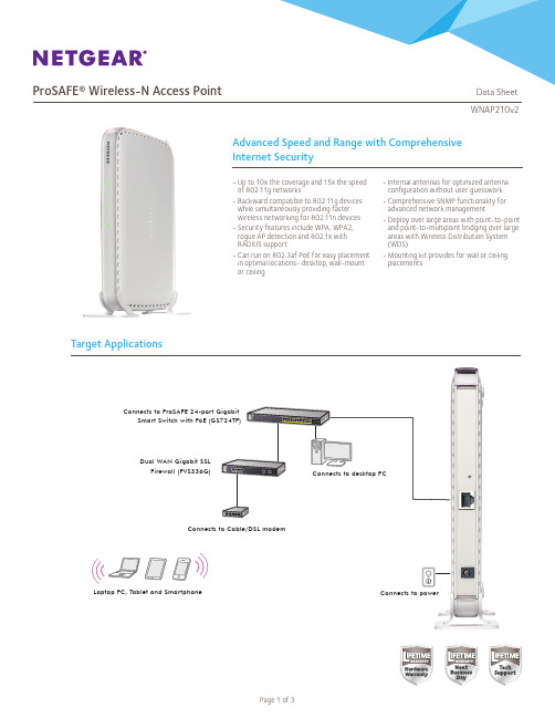
ProSAFE 无线N网络接入点WNAP210v2说明书
Network Management
• Remote configuration and management through Web browser, SNMP or telnet with command line interface (CLI)
• SNMP management supports SNMP MIB I, MIB II, 802.11 MIB a nd proprietary configuration MIB
Yes 5.8 Watts
ProSAFE Dual Band Wireless-N Access Point (WNDAP350)
2.4GHz and 5.0GHz
600Mbps
Yes
10.75 Watts
ProSAFE Dual Band Wireless-N Access Point (WNDAP360)
Block SSID Broadcast Secure SSH Telnet Secure Socket Layer (SSL) Remote management login Peer-to-peer blocking so users may not access another user’s PC MBSSID/VLAN Support WPA Support (WPA2 – Enterprise, 802.11i) User Interface Browser-based Interface Accepts accessory antennas Easy ceiling mounting/wall mounting Controller management
Connects to desktop PC
戴尔 OptiPlex 160L 服务手册说明书
Dell™ OptiPlex™ 160L Service ManualRemoving the Computer CoverControl PanelI/O PanelPower SupplySystem BoardReplacing the Computer CoverTo remove or replace all other 160L components, see the 160L Systems User's Guide .Notes, Notices, and CautionsInformation in this document is subject to change without notice.© 2003 Dell Computer Corporation. All rights reserved.Reproduction in any manner whatsoever without the written permission of Dell Computer Corporation is strictly forbidden.Trademarks used in this text: Dell , the DELL logo, and OptiPlex are trademarks of Dell Computer Corporation.Other trademarks and trade names may be used in this document to refer to either the entities claiming the marks and names or their products. Dell Computer Corporation disclaims any proprietary interest in trademarks and trade names other than its own.Model: MTC2June 2003 Rev. A00NOTE: A NOTE indicates important information that helps you make better use of your computer.NOTICE: A NOTICE indicates either potential damage to hardware or loss of data and tells you how to avoid the problem.CAUTION: A CAUTION indicates a potential for property damage, personal injury, or death.1 control panel2 control panel lever1 control panel lever2 control panel tab3 notch4. Replace the computer cover.Back to Contents PageReplacing the Computer CoverDell™ OptiPlex™ 160L Service Manual1. Ensure that all cables are connected, and fold cables out of the way.2. Ensure that no tools or extra parts are left inside the computer.3.Place the cover on the computer.4.Slide the cover toward the front of the computer until it fits completely into place.3. Connect your computer and any devices to electrical outlets, and turn them on.Back to Contents PageCAUTION: Before you perform this procedure, see the safety instructions in your Setup and Quick Reference Guide .NOTICE: To connect a network cable, first plug the cable into the network wall jack and then plug it into the computer.1 side hinges (3) 4release lever2 front panel 5middle tab3 top tab 6bottom tab4. Remove the two screws that secure the I/O panel to the computer.1 screws (2)2 I/O panel3 sound/USB cable4 tie wrap cord5. Remove the I/O panel and disconnect the sound/USB cable from the I/O panel.1 screws (2)2 I/O panel3 I/O panel cage3. Reattach the front panel to the side hinges, and then rotate it until it snaps onto the front of the computer.1 side hinges2 front panel4. Reinstall the hard drive(s).5. Replace the computer cover.6. Connect your computer and devices to electrical outlets, and turn them on.Back to Contents PageNOTICE: To connect a network cable, first plug the cable into the network wall jack and then plug it into the computer.Main Power ConnectorPeripheral Power Connectors1 power connector (J21) 10 front-panel audio connector (J29)2 hard-drive connector (J23) 11 PCI card Slots (3) (PCI1, PCI2, PCI3)3 CD drive connector (J20) 12 modem telephony connector (J25)4 floppy-drive connector (J18) 13 CD audio connector (J8)5 control panel connector (J28) 14 12V POWER connector (J10)6 battery socket (BT1) 15 processor connector (U16)7 clock jumper (CLEAR CMOS) 16 fan connector (J30)8 front-panel connector (J27) 17 memory module connectors (DDR1, DDR2)NOTICE: Ensure that your computer is turned off and unplugged before you change the jumper settings. Otherwise, damage to your computer or unpredictable results can occur.NOTICE: Before touching anything inside your computer, ground yourself by touching an unpainted metal surface, such as the metal at the back of the computer. While you work, periodically touch an unpainted metal surface to dissipate any static electricity that could harm internal components.(default)jumpered unjumpereda.Locate the Clear Password and Clear CMOS jumpers on the system board.b. Remove the password jumper from its pins.c.Place the password jumper on the Clear CMOS pins and wait approximately 5 seconds.d. Remove the jumper from the Clear CMOS pins and place the jumper back on the password pins.7. Replace the computer cover.8. Connect your computer and devices to electrical outlets, and turn them on.Replacing the System Board1. Shut down the computer through the Start menu.2. Ensure that your computer and attached devices are turned off. If your computer and attached devices did not automatically turn off when you shutdown your computer, turn them off now.3. Disconnect any telephone or telecommunication lines from the computer.4. Disconnect your computer and all attached devices from their electrical outlets, and then press the power button to ground the system board.5. Remove the computer cover.Removing the System Board1. If a floppy drive is installed, remove the floppy drive.2. Remove any installed cards.3. Disconnect all cables from the system board.4. Disconnect the fan power cable from the connector on the system board.5. Remove the shroud/fan assembly.6. Remove the processor heat sink.7. Remove the 12 screws that secure the system board to the computer frame.Four of the 12 screws that secure the system board to the computer frame also secure the heat-sink base to the system board.NOTICE: To connect a network cable, first plug the cable into the network wall jack and then plug it into the computer. CAUTION: Before you perform this procedure, see the safety instructions in your Setup and Quick Reference Guide .NOTICE: To avoid electrostatic discharge, ground yourself by using a wrist grounding strap or by periodically touching an unpainted metal surface (such as the back panel) on the computer.NOTICE: Before you disconnect a device from the computer or remove a component from the system board, verify that the standby power light on the system board has turned off. To locate the light, see "System Board Components ."NOTICE: To disconnect a network cable, first unplug the cable from your computer and then unplug it from the network wall jack.CAUTION: To guard against electrical shock, always unplug your computer from the electrical outlet before opening the cover.NOTICE: Before touching anything inside your computer, ground yourself by touching an unpainted metal surface, such as the metal at the back of the computer. While you work, periodically touch an unpainted metal surface to dissipate any static electricity that could harm internal components. CAUTION: The processor heat sink can get hot. To avoid burns, ensure that the heat sink has had sufficient time to cool before you touch it.1 system board screws (8)2 heat-sink base screws (4)8. Lift the system board out from the computer.9. Place the system board that you just removed next to the replacement system board.1 computer cover2 cover latchBack to Contents Page。
夜猎队长M2移动路由器数据册说明书
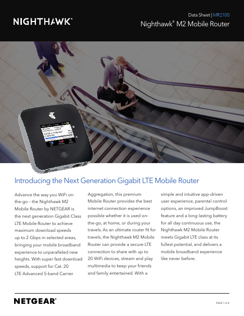
Introducing the Next Generation Gigabit LTE Mobile RouterAdvance the way you WiFi on-the-go – the Nighthawk M2 Mobile Router by NETGEAR is the next generation Gigabit Class LTE Mobile Router to achieve maximum download speedsup to 2 Gbps in selected areas, bringing your mobile broadband experience to unparalleled new heights. With super fast download speeds, support for Cat. 20LTE Advanced 5-band Carrier Aggregation, this premiumMobile Router provides the bestinternet connection experiencepossible whether it is used on-the-go, at home, or during yourtravels. As an ultimate router fit fortravels, the Nighthawk M2 MobileRouter can provide a secure LTEconnection to share with up to20 WiFi devices, stream and playmultimedia to keep your friendsand family entertained. With asimple and intuitive app-drivenuser experience, parental controloptions, an improved JumpBoostfeature and a long-lasting batteryfor all day continuous use, theNighthawk M2 Mobile Routermeets Gigabit LTE class at itsfullest potential, and delivers amobile broadband experiencelike never before.As your ultimate travel router, the Nighthawk M2 is a premium mobile WiFi router, plus MORESUPER FAST WIRELESS INTERNETPARENTAL CONTROL TOUCH SCREENWITH DATA USAGE METER TRAVEL ROUTER MEDIA STREAMING LONG LASTING BATTERY DUAL BAND DUAL CONCURRENT WIFI JUMPBOOST CONNECT UP TO20 DEVICESSIMPLE INTUITIVE APP DRIVEN USER EXPERIENCEIn the homeIn the hotelStream with your Nighthawk M2 MobileRouter to watch your favourites on demandDuring TravelsKeep your entire team connected, andstay productive no matter where you areOn the wayKeep your family entertained by usingyour Nighthawk M2 Mobile Router as amedia hubBring your own secured connection with youand offload to WiFi or Ethernet upon arrival HotelSecured Interneton all WiFi devicesWatch Movies onall WiFi Devices External hard driveConnect to R outerConnect to R outerIn the hotelOn the wayKey Features• Superfast Mobile Broadband Internet to deliver incredible download speeds up to 2 Gbps and upload speeds up to 150Mbps in selected areas.• Supports 4GX LTE Advanced Category 20 with up to 5-band Carrier Aggregation• Media Streaming from USB or external hard drive to all connected devices • LCD Touch Screen Interface• Travel Router with WiFi/Ethernet offloading capabilities• Always-on connection you can count on and share with up to 20 WiFi devices on-the-go• Parental controls to protect or guard access to online content• Reduce network downtime by plugging in to Ethernet LAN/WAN port for instant connectivity.• Simple, intuitive app-driven user experience to monitor data usage, manage device and network settings • Powerful, long-lasting battery for all day continuous use• Improved JumpBoost feature to charge smartphones and small portable USB devices• Two TS-9 connectors available for use with external 4G/3G antennas • Simple setup with no software to install – just power on and connect Technical SpecificationsTechnology / Bands• LTE CAT 20, up to 5-band CA and4x4 MIMO• LTE/4GX 700/900/1800/2100/2600 MHz• 3G 850/900/1900/2100 MHzChipset• Qualcomm SDX24WiFi• Full Dual-Band/Dual-Concurrent WiFi• WiFi 802.11 b/g/n 2.4 GHz;WiFi 802.11 a/n/ac 5 GHzData Usage Meter• Manage your data and how muchyou useMedia• USB with Media Server/NAS capabilitiesMax Theoretical Downlink Speed• 2 GbpsMax Theoretical Uplink Speed• 150 MbpsDimensions• 105.5 (L) x 105.5 (W) x 20.35 (H) mmWeight• 240 g (with battery)External Display• 2.4” Touch LCD panelBattery Life• All day & Night - 5040mAh batteryfor all day useExternal Ports• Gigabit LAN/WAN Port• USB-C Port• USB-A Port for Jump Boost and MediaServer/NAS capabilities• Dual TS-9 external 3G/4G antennaconnectorsPackage Contents• NETGEAR Nighthawk M2 Mobile Router• Removable Lithium Ion (Li-ion) Battery• Battery Cover• QC 2.0 charger and USB Type-C cable• Quick Start Guide• Manufacturer’s warranty card©2019 NETGEAR, Inc. NETGEAR, the NETGEAR Logo, Nighthawk are trademarks of NETGEAR, Inc. The Telstra logo is a registered trade mark of Telstra Corporation Limited, ABN33 051 775 556. Other brand names mentioned herein are for identification purposes only and may be trademarks of their respective holder(s). NETGEAR, Inc., 350 E. Plumeria Drive, San Jose, CA, 95014 USA. Information is subject to change without notice.。
思科 RV160W 路由器快速入门指南-1690805760.1775157说明书

快速入门指南思科 RV160W 路由器装箱清单•思科 RV160W 路由器•电源适配器•本快速入门指南•RoHS 合规信息卡•技术支持联系信息卡•以太网电缆•欧盟指令 2014/53/EU 合规信息(仅适用于欧盟 SKU)欢迎感谢您选择思科 RV160W 路由器。
RV160W 路由器不仅提供可靠的互联网访问连接,而且具备以下功能:•通过多种设置向导简化 UI 使用。
• 4 端口无线 AC VPN 路由器。
•支持 IPv6 防火墙。
•双频 WLAN(2.4GHz 和 5GHz)•企业级一体化小型企业网络。
本指南介绍思科 RV160W 的安装方法以及基于 Web 的设备管理器启动方法。
安装思科 RV160W1为防止设备过热或受损,请注意以下要求:•环境温度 - 请勿在环境温度超过 40°C (104°F) 的区域中使用本设备。
•通风 - 请确保设备周围通风良好。
若以壁挂方式安装设备,请确保散热孔朝向侧面。
•电路过载 - 接通设备电源不得造成电路过载。
•机械负载 - 请确保设备保持水平、平稳,以免出现任何危险情况;同时还应确保设备牢固固定,以防止其滑动或移位。
请勿在设备顶部放置任何物品,因为重量过高会损坏设备。
桌面安装若要将设备放置在桌面上,请将设备放置在平坦的表面上,以便设备依靠其四个橡胶支脚来支撑。
壁挂式安装路由器的底部面板上有两个壁挂槽。
要将路由器安装到墙壁上,需要使用壁挂式安装套件螺钉(随路由器提供)。
路由器壁挂式安装指南当选择路由器在墙壁上的安装位置时,需要考虑电缆限制和墙壁结构。
•安装路由器时,使前面板朝上。
确保将路由器安装在能够看到 LED 的高度。
2思科 RV160W 路由器快速入门指南•确保将电源放置在地板或桌面等水平表面上。
如果电源未得到适度支撑,电源适配器电缆过度拉紧可能会使其从路由器脱落。
•请勿将路由器或其电源安装在靠近任何类型热源(包括暖风出口)的位置。
您可以将路由器安装在空心墙或墙体立柱上。
F2X16 V2系列IP MODEM使用说明书
F2X16V2系列IP MODEM 使用说明书此说明书适用于下列型号产品:客户热线:400-8838-199电话:+86-592-6300320传真:+86-592-5912735网址:地址:厦门集美软件园三期A06栋11层F2X16V2系列IP MODEM使用说明书文档版本密级V1.0.2产品名称:F2X16V2共31页型号产品类别F2116V2GPRS IP MODEM F2A16V2LTE IP MODEM F2C16V2Cat.1IP MODEM文档修订记录日期版本说明作者2020-02-24V1.0.0初建ZDM 2020-04-16V1.0.1更新输入电源范围和产品图片ZDM 2020-05-12V1.0.2增加F2C16型号ZCL2/31著作权声明本文档所载的所有材料或内容受版权法的保护,所有版权由厦门四信通信科技有限公司拥有,但注明引用其他方的内容除外。
未经四信公司书面许可,任何人不得将本文档上的任何内容以任何方式进行复制、经销、翻印、连接、传送等任何商业目的的使用,但对于非商业目的的、个人使用的下载或打印(条件是不得修改,且须保留该材料中的版权说明或其他所有权的说明)除外。
商标声明Four-Faith、四信、、、均系厦门四信通信科技有限公司注册商标,未经事先书面许可,任何人不得以任何方式使用四信名称及四信的商标、标记。
3/31/314注:不同型号配件和接口可能存在差异,具体以实物为准。
目录第一章产品简介 (6)1.1产品概述 (6)1.3工作原理框图 (7)1.4产品规格 (8)第二章安装 (10)2.1概述 (10)2.2开箱 (10)2.3安装与电缆连接 (10)2.4电源说明 (13)2.5指示灯说明 (13)第三章参数配置 (14)3.1配置连接 (14)3.2参数配置方式介绍 (14)3.3参数配置详细说明 (14)3.3.1配置工具运行界面 (15)3.3.2设备上电 (16)3.3.4中心服务 (22)3.3.5串口 (23)3.3.6无线拔号 (24)3.3.7全局参数 (26)3.3.8设备管理 (27)3.3.9其它功能项 (28)第四章数据传输试验环境测试 (29)4.1试验环境网络结构 (29)4.2测试步骤 (29)5/316/31第一章产品简介1.1产品概述F2X16V2系列IP MODEM 是一种物联网无线数据终端,利用公用蜂窝网络为用户提供无线长距离数据传输功能。
ZM602系列Wi-Fi模块用户手册说明书

ZM602系列Wi-Fi模块用户手册Wi-Fi模块UM01010101 1.2 Date:2022/9/16类别内容关键词ZM602模块,Wi-Fi+BLE,用户手册摘要©2022 Guangzhou ZHIYUAN Electronics Co., Ltd.修订历史文档版本日期原因V1.00 2022.04.25 首次发布V1.01 2022.08.18 新增产品实物图;新增特色功能说明;更新产品选型表;优化快速使用说明;优化BLE数据透传说明;新增数据通道说明;新增串口命令:读取设备MAC地址、读取STA连接状态、读取连接到本设备的STA列表目录1. 产品简介 (1)1.1 概述 (1)1.2 产品特性 (1)1.3 典型应用 (2)1.4 产品选型表 (2)2. 快速使用说明 (3)2.1 与设备建立连接 (3)2.2 设置Wi-Fi工作模式 (4)2.3 使用设备连接其他热点 (5)3. 产品功能 (7)3.1 Wi-Fi数据透传 (7)3.1.1 场景一:模块数据互传 (7)3.1.2 场景二:模块与笔记本电脑进行数据互传 (12)3.2 BLE数据透传 (13)4. 工作模式 (16)4.1 网络工作模式 (16)4.1.1 数据通道 (16)4.1.2 TCP Server模式 (17)4.1.3 TCP Client模式 (18)4.1.4 UDP Client模式 (18)4.1.5 UDP Server模式 (18)4.1.6 MQTT Client模式 (19)4.2 Wi-Fi工作模式 (19)4.2.1 AP模式 (19)4.2.2 STA模式 (19)4.2.3 AP+STA模式 (19)5. 配置设备 (20)5.1 网页配置 (20)5.1.1 登录设备网页 (20)5.1.2 系统 (20)5.1.3 专家 (20)5.1.4 串口 (20)5.1.5 网络 (21)5.1.6 无线 (21)5.1.7 热点 (22)5.1.8 用户登录 (22)5.1.9 系统管理 (22)5.1.10 软件更新 (22)5.2 蓝牙快速配网 (23)5.3 串口协议指令 (25)5.3.1 基本原则 (25)5.3.2 封包结构 (26)5.3.3 命令列表 (28)5.3.4 事件列表 (28)5.3.5 命令解析 (29)6. 免责声明 (42)ZM602系列Wi-Fi模块用户手册Wi-Fi模块1.产品简介1.1 概述ZM602系列Wi-Fi模块是广州致远电子股份有限公司基于博流BL602系列芯片开发的高性能Wi-Fi+BLE模块产品。
FT160B用户手册V2[1].0
![FT160B用户手册V2[1].0](https://img.taocdn.com/s3/m/3373da275901020207409cb3.png)
FT160B网管型PDH光端机用户手册本手册著作权属迈普(四川)通信技术有限公司所有,未经著作权人书面许可,任何单位或个人不得以任何方式摘录、复制或翻译。
侵权必究。
策划:研究院资料服务处* * *迈普通信技术有限公司地址:成都市高新区九兴大道16号迈普大厦技术支持热线:8008868668传真:(+8628)85148948E-mail:support@网址:邮编:610041* * *版次:2005年7月第2版编号:mpt050705FT160B网管型PDH光端机用户手册目录前言 (1)目的 (1)读者对象 (1)手册结构 (1)本书约定 (1)第一章简介 (2)1.1 概述 (2)1.2 外观说明 (5)1.2.1 前面板视图 (5)1.2.2 前面板指示灯说明 (6)1.2.3 后面板视图 (9)第二章设备安装 (11)2.1 安装准备 (11)2.1.1 电源要求 (11)2.1.2 运行缓急要求 (11)2.1.3 货物检查 (11)2.2 硬件安装 (11)2.2.1 机械安装 (11)2.2.2 电气安装 (12)2.2.3 接插件说明 (12)FT160B网管型PDH光端机用户手册第三章系统基础 (14)3.1 环回和测试原理 (14)3.1.1 用户环 (14)3.1.2 网络环 (14)3.2 系统时钟源的选择和配置 (15)3.2.1 以太接口的时钟源选择和配置 (15)3.2.2 V35接口的时钟源选择和配置 (15)3.2.3 E1接口的时钟源选择和配置 (16)3.3 系统配置方式说明 (17)3.4 典型应用举例 (17)第四章系统的操作和维护 (19)4.1 FT160B拨码开关及按键功能 (19)4.2 FT160B工作模式说明 (23)4.2.1 FT160B工作模式介绍 (23)4.2.2 工作模式典型应用 (23)4.2.3 跟随模式下的配置说明 (24)4.3.3 环回和测试的操作 (25)第五章软件升级 (26)第六章光端机常用故障排除方法 (27)6.1 常见启动故障分析与排除 (27)6.2 室外常见组网应用故障排除方法 (27)6.2.1 FT160B-1E1SAC/DC、FT160B-1VSAC常见故障排除方法 (28)6.2.2 FT160B-1FESAC常见故障排除方法 (29)FT160B网管型PDH光端机用户手册前言目的为帮助用户更好地了解、使用及日常维护FT160B,特制定本手册。
WT-160用户手册V1.0

2. 设备安装 .....................................................................................................................................4 2.1. 装箱清单 .............................................................................................................................4 2.2. 硬件连接 .............................................................................................................................4 2.2.1. 2.2.2. 2.2.3. 2.2.4. 接地线连接 ..............................................................................................................4 电源线连接 ..............................................................................................................4 网线连接 ..................................................................................................................4 射频电缆连接 ..........................................................................................................4
Linksys WRT160N无线路由器高速“飞碟”
Linksys WRT160N无线路由器高速“飞碟”
冯亮
【期刊名称】《《微型计算机》》
【年(卷),期】2008(000)019
【摘要】如果你是高清玩家或硬件发烧友,需要802.11n无线网络传输1080p 高清视频和大容量文件,同时又在意产品的外观设计,不妨关注我们测试的这款Linksys WRT160N无线路由器;
【总页数】1页(P73)
【作者】冯亮
【作者单位】
【正文语种】中文
【中图分类】TP334.7
【相关文献】
1.为企业开辟的无线高速公路 Linksys by Cisco WRT320N无线路由器 [J], Orlane
2.Linksys绚酷新品WRT160N登陆中国 [J],
3.碟影 Linksys WRT54G2/Linksys WRT160N [J], 张越
4.蝶影Linksys WRT54G2/Linksys WRT160N [J],
5.Linksys WRT160N无线路由器高速"飞碟" [J],
因版权原因,仅展示原文概要,查看原文内容请购买。
TT DULWAN 中文设置说明
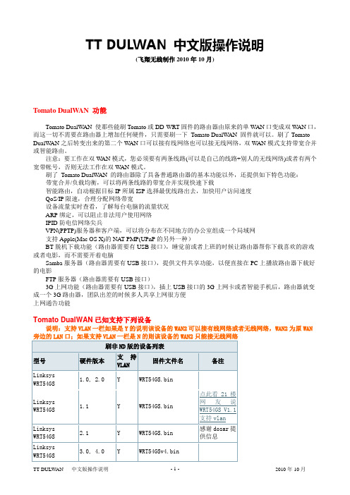
TT DULWAN 中文版操作说明(飞翔无线制作2010年10月)Tomato DualW AN 功能Tomato DualWAN 使那些能刷Tomato或DD-WRT固件的路由器由原来的单WAN口变成双WAN口,而这一切不需要在路由器上增加任何硬件,只需要刷一下Tomato DualWAN 固件就可以。
刷了Tomato DualWAN之后转变出来的第二个WAN口可以接有线网络也可以接无线网络,双WAN模式支持带宽合并或智能路由。
注意:要工作在双W AN模式,您必须要有两条线路(可以是自己的线路+别人的无线网络)或者有两个宽带帐号,否则无法工作在双W AN模式。
刷了Tomato DualWAN 的路由器除了具备普通路由器的基本功能以外,还提供如下特色功能:带宽合并/负载均衡,可以将两条线路的带宽合并实现快速下载智能路由,自动根据目标IP所属ISP选择最优线路出去,加快用户访问速度QoS/IP限速,合理分配网络带宽设备流量实时查看,了解每台电脑的流量状况ARP绑定,可以阻止非法用户使用网络IPID防电信网络尖兵VPN(PPTP)服务器和客户端,可以将分布在不同地方的办公室组成一个局域网支持Apple(Mac OS X)的NA T-PMP(UPnP的另外一种)BT脱机下载功能(路由器需要有USB接口),睡觉前或者上班的时候让路由器帮你下载喜欢的游戏或者电影,而不需要开着电脑Samba服务器(路由器需要有USB接口),提供文件共享功能,以便直接在PC上播放路由器下载好的电影FTP服务器(路由器需要有USB接口)3G上网功能(路由器需要有USB接口),插上USB接口的3G上网卡或者智能手机后,路由器就变成一个3G路由器,团队出差的时候多人共享上网很方便上网通告功能Tomato DualWAN已知支持下列设备说明:支持VLAN一栏如果是Y的说明该设备的WAN2可以接有线网络或者无线网络,WAN2为原WAN不能接有线网络,但是可以作为无线客户端接入到别人的无线网络。
NETGEAR R6300v2智能无线路由器安装指南说明书
NETGEAR vous recommande d'utiliser uniquement les ressources d'assistance officielles NETGEAR.
4
4. Connectez un ordinateur.
Routeur
Modem
Ordinateur
Vous pouvez utiliser un câble Ethernet ou établir une connexion sans fil. • Pour une connexion câblée, utilisez un câble Ethernet (non
Avis important: Assurez-vous de retirer la pellicule dde l'utiliser.
1. Préparez votre modem.
Débranchez votre modem. S'il est équipé d'une batterie de secours, retirez-la.
Routeur
Modem
a. Branchez le cordon d'alimentation à votre modem, puis allumez ce dernier. (Remettez en place la batterie si vous l'aviez retirée précédemment.)
Attendez-que le voyant Wi-Fi s'allume.
LINKSYS WRT160NL 说明书
USER GUIDE Wireless-N Broadband Routerwith Storage LinkModel: WRT160NLtrademarks of their respective holders.Chapter 1: Product Overview 1 Front Panel. . . . . . . . . . . . . . . . . . . . . . . . . . . . . . . . . . . . . . . . . . . . . . . . . . 1 Back Panel . . . . . . . . . . . . . . . . . . . . . . . . . . . . . . . . . . . . . . . . . . . . . . . . . . 1 Bottom Panel . . . . . . . . . . . . . . . . . . . . . . . . . . . . . . . . . . . . . . . . . . . . . . . . 2 Chapter 2: Wireless Security Checklist 3 General Network Security Guidelines. . . . . . . . . . . . . . . . . . . . . . . . . . . . . . . . . 3 Additional Security Tips . . . . . . . . . . . . . . . . . . . . . . . . . . . . . . . . . . . . . . . . . 3 Chapter 3: Advanced Configuration 4 Setup > Basic Setup . . . . . . . . . . . . . . . . . . . . . . . . . . . . . . . . . . . . . . . . . . . . 4 Setup > DDNS. . . . . . . . . . . . . . . . . . . . . . . . . . . . . . . . . . . . . . . . . . . . . . . . 8 Setup > MAC Address Clone. . . . . . . . . . . . . . . . . . . . . . . . . . . . . . . . . . . . . . . 9 Setup > Advanced Routing . . . . . . . . . . . . . . . . . . . . . . . . . . . . . . . . . . . . . . . 9 Wireless > Basic Wireless Settings . . . . . . . . . . . . . . . . . . . . . . . . . . . . . . . . . . .10 Wireless > Wireless Security . . . . . . . . . . . . . . . . . . . . . . . . . . . . . . . . . . . . . . .12 Wireless > Wireless MAC Filter. . . . . . . . . . . . . . . . . . . . . . . . . . . . . . . . . . . . . .14 Wireless > Advanced Wireless Settings . . . . . . . . . . . . . . . . . . . . . . . . . . . . . . . .15 Security > Firewall . . . . . . . . . . . . . . . . . . . . . . . . . . . . . . . . . . . . . . . . . . . . .16 Security > VPN Passthrough. . . . . . . . . . . . . . . . . . . . . . . . . . . . . . . . . . . . . . .17 Storage > Disk . . . . . . . . . . . . . . . . . . . . . . . . . . . . . . . . . . . . . . . . . . . . . . .17 Storage > Administration . . . . . . . . . . . . . . . . . . . . . . . . . . . . . . . . . . . . . . . .20 Access Restrictions > Internet Access . . . . . . . . . . . . . . . . . . . . . . . . . . . . . . . . .21 Applications and Gaming > Single Port Forwarding. . . . . . . . . . . . . . . . . . . . . . . .22 Applications and Gaming > Port Range Forwarding . . . . . . . . . . . . . . . . . . . . . . .23 Applications & Gaming > Port Range Triggering . . . . . . . . . . . . . . . . . . . . . . . . . .23 Applications and Gaming > DMZ . . . . . . . . . . . . . . . . . . . . . . . . . . . . . . . . . . .24 Applications and Gaming > QoS . . . . . . . . . . . . . . . . . . . . . . . . . . . . . . . . . . . .24 Administration > Management. . . . . . . . . . . . . . . . . . . . . . . . . . . . . . . . . . . . .26 Administration > Log . . . . . . . . . . . . . . . . . . . . . . . . . . . . . . . . . . . . . . . . . . .27 Administration > Diagnostics . . . . . . . . . . . . . . . . . . . . . . . . . . . . . . . . . . . . . .28 Administration > Factory Defaults. . . . . . . . . . . . . . . . . . . . . . . . . . . . . . . . . . .28 Administration > Firmware Upgrade . . . . . . . . . . . . . . . . . . . . . . . . . . . . . . . . .29 Status > Router . . . . . . . . . . . . . . . . . . . . . . . . . . . . . . . . . . . . . . . . . . . . . . .29 Status > Local Network . . . . . . . . . . . . . . . . . . . . . . . . . . . . . . . . . . . . . . . . . .30 Status > Wireless Network . . . . . . . . . . . . . . . . . . . . . . . . . . . . . . . . . . . . . . . .30 Appendix A: Troubleshooting 31 Appendix B: How to Install and Access USB Storage 33 Overview. . . . . . . . . . . . . . . . . . . . . . . . . . . . . . . . . . . . . . . . . . . . . . . . . . .33 Install the USB Storage Device . . . . . . . . . . . . . . . . . . . . . . . . . . . . . . . . . . . . .33 Access the USB Storage Device. . . . . . . . . . . . . . . . . . . . . . . . . . . . . . . . . . . . .33 Create a Shortcut to a Shared Folder . . . . . . . . . . . . . . . . . . . . . . . . . . . . . . . . .34 Advanced Configuration (Advanced Users Only). . . . . . . . . . . . . . . . . . . . . . . . . .36Appendix C: Specifications 39 Appendix D: Warranty Information 40 Limited Warranty. . . . . . . . . . . . . . . . . . . . . . . . . . . . . . . . . . . . . . . . . . . . . .40 Appendix E: Regulatory Information 42 FCC Statement . . . . . . . . . . . . . . . . . . . . . . . . . . . . . . . . . . . . . . . . . . . . . . .42 FCC Radiation Exposure Statement . . . . . . . . . . . . . . . . . . . . . . . . . . . . . . . . . .42 Safety Notices. . . . . . . . . . . . . . . . . . . . . . . . . . . . . . . . . . . . . . . . . . . . . . . .42 Industry Canada Statement . . . . . . . . . . . . . . . . . . . . . . . . . . . . . . . . . . . . . . .42 Avis d’Industrie Canada. . . . . . . . . . . . . . . . . . . . . . . . . . . . . . . . . . . . . . . . . .43 Wireless Disclaimer . . . . . . . . . . . . . . . . . . . . . . . . . . . . . . . . . . . . . . . . . . . .43 Avis de non-responsabilité concernant les appareils sans fil . . . . . . . . . . . . . . . . . .43 User Information for Consumer Products Covered by EU Directive 2002/96/EC on WasteElectric and Electronic Equipment (WEEE). . . . . . . . . . . . . . . . . . . . . . . . . . . . . .44 Appendix F: Software End User License Agreement 48 Cisco Products . . . . . . . . . . . . . . . . . . . . . . . . . . . . . . . . . . . . . . . . . . . . . . .48 Software Licenses . . . . . . . . . . . . . . . . . . . . . . . . . . . . . . . . . . . . . . . . . . . . .48Wi-FiclientsupportAntennaports connect to the male R-SMA connectors ofthe included antennas.Internetconnect your cable or DSL Internet connection.4,connect the Router to computers on your wirednetwork and other Ethernet network devices.Power The Power port connects to the included Arraypower adapter.2.5-3.0 m m4-5 mm 1-1.5 mmNote: Mounting hardware illustrations are nottrue to scale.152 mm1.devices with specific MAC addresses. For example, you can specify the MAC address of each computer in your home so that only those computers can access your wireless network.The first screen that appears is the Basic Setup screen. This allows you to change the Router’s general settings.Some DSL-based ISPs use PPPoE (Point-to-Point Protocol over Ethernet) to establish Internet connections. If you are connected to the Internet through a DSL line, check with your ISP to see if they use PPPoE. If they do, you will have PPPoE.Username and Password Enter the Username and Password provided by your ISP.Service Name If provided by your ISP, enter the Service Name.IP address of the ISP server.DNS 1-3•Your ISP will provide you with at least one DNS (Domain Name System) server IP address.Keep Alive: Redial Period If you select this option, the Router will periodically check your Internet connection. If you are disconnected, then the Router will automatically re-establish your connection. To useOptional SettingsHost Name and Domain Name These fields allow you to supply a host and domain name for the Router. Some ISPs, usually cable ISPs, require these names as identification. You may have to check with your ISP to see if yourDHCP Server DHCP is enabled by factory default. If you already have a DHCP server on your network, or you do not want a DHCP server, then select Disabled (no other DHCP features will be available).IP Address Range Displayed here is the range of available IP addresses.Client Lease Time The Client Lease Time is the amount of time a network user will be allowed connection to the Router with their current dynamic IP address. Enter theSetup > DDNS > TZOE-mail Address, TZO Key, and Domain Name Enter the settings of the account you set up with TZO.IP Address The Router’s Internet IP address is displayed here. Because it is dynamic, it will change.The status of the DDNS service connection is displayed here.select Enabled.MAC Address Enter the MAC Address registered with your ISP here.type(s) of advanced functions you use. Dynamic Routing automatically adjusts how packets travel on your network. Staticdestination.A static route is a pre-determined pathway that network information must travel to reach a specific host or network. Enter the information described below to set up a new static route.as wireless adapters, that support Wi-Fi Protected Setup, then you can use Wi-Fi Protected Setup.Configuration To manually configure yournetwork, select Manual. Proceed to Basic Wireless Settings, page 10. To use Wi-Fi Protected Setup, Wide ChannelWidth setting, then this setting will be available for yourEnter the PIN number in the1. field on this screen.Click2. Register.keys. The default is 3600 seconds.Security Mode > WPA EnterpriseEncryption WPA supports two encryption methods, TKIP and AES, with dynamic encryption keys. Select the type of TKIP or AES. The default is TKIP.RADIUS Server Enter the IP address of the server. RADIUS Port Enter the port number of the server. The 1812.Shared Secret Enter the key shared between the Router and the server.40/64 bits (10 hex digits) or 104/128 bits (26 hex digits). The default is 40/64 bits (10 hex digits). Passphrase Enter a Passphrase to automatically generate WEP keys. Then click Generate.If you did not enter a Passphrase, enter the WEP key(s) manually.Select which TX (Transmit) Key to use. The defaultSave Settings to apply your changes, or click Cancel to clear your changes.Wireless Client ListWireless Client Listscreen shows computers and other devices on the wireless network. The list can be sorted by Client Name, Interface, IP Address, MAC Address, and Status.AP Isolation This isolates all wireless clients and wireless devices on your network from each other. Wireless devices will be able to communicate with the Router but not orSystemNOTauthentication, the sender and recipient use a WEP key for authentication. Selectauthentication.Basic Rateof transmission but a series of rates at which the Router candata transmission. If you want to specify the Router’s ratekeep the default, Auto. To disable this option, select Disabled.Beacon Interval Enter a value between 1 and 65,535 milliseconds. The Beacon Interval value indicates theSecurity > FirewallVPN PassthroughPassthrough Internet Protocol Security (IPSec) is a suite of protocols used to implement secure exchange of packets at the IP layer. To allow IPSec tunnels to pass through the Router, keep the default, Enabled.Passthrough Point-to-Point Tunneling Protocolallows the Point-to-Point Protocol (PPP) to be tunneled through an IP network. To allow PPTP tunnels touser groups, admin and guest.)Disk Management screen, click Close.To format a disk and create a new partition, selectthe disk you want to format, and then click Format Disk. (Ifyour disk was formatted with multiple partitions, then theformatting will delete them and create a single partition.)Claim Disk screen appears.Use this screen to add a shared folder.Available Groups To allow a group access to the sharedfolder, select it, and then click the >> button.Groups with Access To block a group from accessing theshared folder, select it, and then click the << button.If you have UPnP AV-enabled (or DLNA-certified) devices home, then you can use the Router as a mediaExamples of UPnP AV-enabled devices include amedia adapter, a gaming console with a built-in media player, or a digital picture frame.For example, if you have a digital media adapter that sends your entertainment system, then the digital media adapter can locate the Router using the UPnP AV standard. The folders you specify can then be accessed and played by the digital media adapter.Create aMedia Folder, page 19.Auto-scan every __ To automatically scan the media folders, select this option. Then select the appropriate interval: 2 Hours (default), 6 Hours, 12 Hours, 24 Hours, or 48 Hours.screen.On the Media Server screen, click Save Settings to apply your changes, or click Cancel Changes to clear your changes.Storage > AdministrationInformationName Enter the server name for the Router; it will be used for the disk and media server features. Use only alphanumeric characters (letters A to Z and numbers 0 to 9) in the server name. The default is WRT160NL. Workgroup Name Enter the workgroup name for the should match the workgroup name of the computers on your local network. The Router’s default is workgroup.Proceed to Create or Edit a Group Account, page 20. Delete To delete a group, click this button.Create or Edit a Group AccountGroup AccountGroup NameUser AccountUser AccountCreate a name for the user.Full Name Enter the actual name of the user.Description Enter keywords to describe the user.Enter the password that the user will use forSummarypolicy will be in effect, or select 24 Hours.can block websites with specific URL addresses. Enter each URL in a separate Website Blocking by URL field.You can also block websites using specific keywords. Enter each keyword in a separate Website Blocking by Keyword field.can filter access to various services accessedthe Internet, such as FTP or telnet. (You block up to three applications per policy.) From the Applications list, select the application you want to block. Then click the >> button to move it toApplications and Gaming > Port Range Forwarding Port Range TriggeringApplication Name Enter the application name of the trigger.select and complete the IP address range fields. Destination If you want to specify the DMZ host by IPaddress, select IP Address and enter the IP address in the field provided. If you want to specify the DMZ host by MAC address, select MAC Address and enter the MAC You can configure the support and No Acknowledgement settings in this section.WMM Support If you have other devices that support Wi-Fi Multimedia (WMM) on your network, keep the default, Enabled. Otherwise, select Disabled.Port Range Enter the port range that the application will be using. For example, if you want to allocate bandwidth for FTP, you can enter 21-21. If you need services for anapplication that uses from 1000 to 1250, you enter 1000-MAC Address Enter the MAC address of your device.Select the appropriate priority: High, Medium (Recommend), Normal, or Low.to save your changes. Your new entry will appearSelect the appropriate priority: High (Recommend), Medium, Normal, or Low.to save your changes. Your new entry will appearscreen shows if the test is successful. Click Close to return to the Diagnostics screen. Click Stop to stop the test.Restore All Settings To reset the Router’s settings to the defaults, click this button and then follow the on-screen instructions. Any settings you have saved will be lost when the default settings are restored.Administration > Firmware UpgradeNOTE:The Router may lose the settings youhave customized. Before you upgrade itsfirmware, write down all of your custom settings.After you upgrade its firmware, you will have tore-enter all of your configuration settings. Firmware Upgradeupgrading the firmware, download the Router’sStatus > Local NetworkLocal NetworkMAC Address The MAC address of the Router’s local, wired interface is displayed.Router IP Address The Router’s IP address, as it appears on your local network, is displayed.Mask The Subnet Mask of the Router isDHCP Clients TableSelect1. Tools > Internet Options.Click the2. Connections tab.Select3. Never dial a connection. Make sure the Router and your computer use the same workgroup name. (The default workgroup name of the Router is workgroup. In Windows Vista, right-click the Computer icon and select Properties. Click Advancedscreen; refer to Storage > Administration, page 20.can change this name on the Storage > Administration screen; refer to Storage > Administration, page 20.On your desktop, double-click the Network icon.2.Select Drive LetterAccess Mapped DriveOn your desktop, double-click the Computer icon.Enter Account User Name and Password Array User accounts are set up on the Storage >A dministrationscreen; for more information, refer to Create a UserAccount, page 38.Map Network DriveFrom the Drive drop-down menu, select an available drive letter.> Windows Explorer.Advanced Configuration (Advanced Users Only)Tocreate shared folders, user groups, and user accounts. Access the Web-Based UtilityTo access the web-based utility, launch the web browser on your computer, and enter the Router’s default IP address,Storage > DiskTo create a shared folder, click Create Share.select Share entire Partition and proceed to step 7. If you do not want to share the entire partition, thenspecify the folder you do want to share. 9.Create a User Group Account1.2.Group AccountIn the4. Name field, create a name for the user.In the5. Full Name field, enter the actual name of theuser.Unit Weight 9.98 oz (283 g)Power 12V / 1.5A (switching) Certifications FCC, UL, cUL, IC, RSS210, CEAPPLICABLE LAW, ALL SOFTWARE PROVIDED BY LINKSYS WITH THE PRODUCT, WHETHER FACTORY LOADED ON THE PRODUCT OR CONTAINED ON MEDIA ACCOMPANYING THE PRODUCT, IS PROVIDED “AS IS” WITHOUT WARRANTY OF ANY KIND. Without limiting the foregoing, Linksys does The telephone number for Linksys Technical Support in your area can be found in the product User Guide and at . Have your product serial number and proof of purchase on hand when calling. A。
RG-WALL160系列防火墙快速指南(光盘)
RG-WALL 160E/T/M系列防火墙快速指南(V1.0)(内部资料,严禁复制)福建星网锐捷网络有限公司版权所有侵权必究目录一、概述 (3)二、防火墙硬件描述 (3)三、防火墙安装 (4)2.1 温度/湿度要求 (5)2.2 洁净度要求 (5)2.3 抗干扰要求 (5)四、通过CONSOLE口命令行进行管理 (6)五、通过WEB界面进行管理 (13)六、常见问题解答FAQ (19)一、概述RG-WALL防火墙缺省支持两种管理方式:CONSOLE口命令行方式通过网口的WEB(https)管理CONSOLE口命令行方式适用于对防火墙操作命令比较熟悉的用户。
WEB方式直观方便,为保证安全,连接之前需要对管理员身份进行认证。
要快速配置使用防火墙,推荐采用CONSOLE 口命令行方式;日常管理监控防火墙时,WEB方式则是更方便的选择。
安装防火墙之前,请您务必阅读本指南的“二、三”两节。
如果希望使用CONSOLE口命令行方式管理防火墙,请您仔细阅读本指南的第四节;如果希望使用WEB方式管理防火墙,请您仔细阅读本指南的第五节。
防火墙主要以两种方式接入网络:路由方式和混合方式。
在路由方式下,配置完防火墙后您可能还需要把受保护区域内主机的网关指向防火墙;混合方式时,由防火墙自动判定具体报文应该通过路由方式还是透明桥方式转发,如果为透明桥方式,则不用修改已有网络配置。
二、防火墙硬件描述RG-WALL160M系列防火墙前面板示意图如下图所示:RG-WALL160T系列防火墙前面板示意图如下图所示:RG-WALL160E系列防火墙前面板示意图如下图所示:说明如下:三、防火墙安装1.安全使用注意事项本章列出安全使用注意事项,请仔细阅读并在使用RG-WALL防火墙过程中严格执行。
这将有助于您更安全地使用和维护您的防火墙。
(1)您使用的RG-WALL防火墙采用220V交流电源,请确认工作电压并且务必使用三芯带接地电源插头和插座。
维维电子 T-BERD 5800v2 软件更新指南说明书
Viavi MTS/T-BERD 5800v2Software Update InstructionsSeptember 27, 2017Table of ContentsScope (2)work Upgrade (2)B Upgrade (5)3.StrataSync (8)ScopeThere are three methods to update T-BERD 5800v2 software:work upgrade - Use this method to update your T-BERD via an Internet connection.B upgrade - Use this method to update your T-BERD with a USB thumb drive.3.StrataSync upgrade - Use this method if your T-BERD 5800v2 is managed using Viavi’s StrataSyncAsset Management system.The T-BERD must be connected to AC Power, regardless of update method.work UpgradeStep Action Details1.Power On Press and hold the ON/OFF button to turn on the T-BERD 5800v2.2.AC Power Connect the AC power adapter to thepower connector on the side of theT-BERD 5800v2.N Connection Connect the Ethernet ManagementPort on the side of T-BERD 5800v2to a network connection with internetaccess, using CAT 5E or better cable.4.System Press the System icon, , at the top of the start-up screen, to display theSystem Menu.work Settings Press the Network icon,, to display LAN Settings. Set IP Mode to“DHCP” for automatic IP address assignment or “Static” for manual input.After configuring LAN settings, press the System icon, , to redisplaythe System Menu.6. Upgrade Press the Upgrade icon,, to display upgrade methods.Network Upgrade Pressto displayupgrade settings. Ensure that Server Address= “”7.Connect Press to showthe upgrade versions available at . Start Upgrade P ress, and press to initiate the upgrade.B UpgradeStep Action Details Using an internet browser on your PC or laptop, go to /2.5800v2 Click onto display the T-BERD 5800v2 upgrade portal.3.Download Click on the US/Canadian Flag, , and click to downloadthe current software revision from the North American download server.There are choices for EMEA and APAC Save it to your desktop.B Stick Insert a USB thumb drive into the USB port on your PC or laptop.5.Extract Open and run the downloaded file, enter the path of the USB stick, and pressto extract files.6.Eject Safely eject the USB drive from your PC or Laptop7.Power on T-BERD Press and hold the ON/OFF button to turn on the T-BERD 5800v2.8.AC Power Connect the AC power adapter to thepower connector on the side of theT-BERD 5800v2.B Connect the USB Thumb Drive to oneof the USB ports on the side of theT-BERD 5800v2. An 8GB or smallerdrive is recommended.10.System Press the System icon, , at the top of the start-up screen, to display theSystem Menu.11.Upgrade Press the Upgrade icon,, to display upgrade methods.B Upgrade Press to display upgrade versionsavailable on the USB stick.13.Start Upgrade Press . Press to initiate the upgrade.3.StrataSyncStep Action Details1.Power On Press and hold the ON/OFF button to turn on the T-BERD 5800v2.2.AC Power Connect the AC power adapter to thepower connector on the side of theT-BERD 5800v2.N Connection Connect the Ethernet ManagementPort on the side of T-BERD 5800v2to a network connection with internetaccess, using CAT 5E or better cable.4.System Press the System icon, , at the top of the start-up screen, to display theSystem Menu.work Settings Press the Network icon,, to display LAN Settings. Set IP Mode to“DHCP”for automatic IP address assignment or “Static” for manual input.After configuring LAN settings, press the System icon, , to redisplaythe System Menu.6.StrataSync Press the StrataSync icon,, to display StrataSync Settings. Ensurethat Account ID and Technician ID match those of your StrataSync account.7.Sync Press to sync your T-BERD 5800v2 and initiate upgradesauthorized by your StrataSync System Administrator. If an upgrade has beenassigned you will receive a message box telling you that an upgrade isavailable and prompting you to OK or Cancel. If you were expecting ancontact your company’s Stratasync Admin.。
- 1、下载文档前请自行甄别文档内容的完整性,平台不提供额外的编辑、内容补充、找答案等附加服务。
- 2、"仅部分预览"的文档,不可在线预览部分如存在完整性等问题,可反馈申请退款(可完整预览的文档不适用该条件!)。
- 3、如文档侵犯您的权益,请联系客服反馈,我们会尽快为您处理(人工客服工作时间:9:00-18:30)。
WRT160Nv2中文手册
按旧的路由器连接好网线后再操作下面的步骤
(如果是笔记本,先用赠送的蓝色网线连接电脑,才能进入路由器管理页面,因为安全问题,默认无线是登不进管理员页面的。
)
【1】打开浏览器网址框输入192.168.1.1后按enter键出现一个弹框,输入默认登录帐号admin 密码是admin
【2】进入后就是下图,
【3】按下图操作,点击第一个框,下拉选择PPPOE (这里只举例是自己拉的网线,如果和别人共用网线,猫在自己家,设置还是一样。
如果猫在别人家,下拉选择DHCP)
网密码。
(拉网线的合同纸上写了帐号和密码,不知道请打电话10000询问)
【5】输入完帐号密码后,不要点击其它选项。
把网页拉到最下面,点击蓝色的Save Settings保存。
点击后等待一分钟左右,如果没有输错帐号密码或欠费,就
可以上网了。
下面是设置WIFI 密码
【6】默认是没有设置wifi密码的,周围人多建议要设置密码,重复步骤【1】然后点击中间位置的灰色字体【Wireless】,出现下图,按照下图设置一样就可以了,密码要8位数以上。
最后点击下边的【Save Settings】保存。
密码参考:广州北京路88号密码就设置成大写GZBJL88H 告诉亲朋好友又方便易记。
亲测,万能WIFI破解不了的。
这个页面,
首页点击横栏的【wireless】,再点击横栏下面的【wireless Security 】。
然后按照图片里的,除了密码两个字,其他一模一样设置。
第三个框一定要选AES 。
否则手机上网速度比较慢。
安全/效率注意事项:
1、新的光猫都是自带路由功能经常和路由器ip地址冲突。
而以前的adsl 猫就不会冲突
解决方法:进入路由器页面找到192.168.1.1 改成192.168.2.1 保存(以后要进入路由器就变成192.168.2.1 这个地址)
2、因为思科的安全策略,笔记本、手机以无线方式都不能进入本路由器管理页面。
显示错误页面。
解决方法:需要用网线进入。
3、迅雷这一类下载软件需要自己在路由器管理页面里面开启UPnP。
