AWT6281RM20P8中文资料
芯片封装与焊接技术-2

DIP
SIP
第15页 / 共97页
HR-培训中心
芯片封装形式
SOT (Small Outline Transistor:小外型晶体管)
推测产品功能 器件名称
MAX 232 A C P E +
MAX-->Maxim 公司名, 232-->232接口芯片,A-->A 档 C-->民用级,P-->DIP 封装,E-->16脚,+ -->无铅产品
第27页 / 共97页
HR-培训中心
芯片命名规则
芯片型号含义
不同芯片厂商和系列,含义不同,具体依据产品datasheet 主要厂商芯片丝印命名规则说明
1
27
B9
AB
注意:字母序列中没有I\O\S
第20页 / 共97页
HR-培训中心
芯片引脚方向识别
无引脚标示
无方向区分
圆形金属封装,从识别标记开始+顺时针方向
第21页 / 共97页
HR-培训中心
芯片引脚方向识别
晶体管识别方法
二极管识别方法
- 肉眼识别法 (色环、金属探针等)
负极 正极
INTERSIL
XXX XXXX X X X X
1
2-->器件型号
3-->电性能选择 4-->温度范围:A、B、I、M 5-->封装形式:A~Q 6-->管脚数量:A、B、Q等
2
3 4 5 6
1-->前缀:器件类型(线性电路\存储器\模拟开关等)
创维8G20机芯彩电图纸
创维RM系列液晶彩电8G20、8G21机芯 维修手册
第一部分:8G20、8G21 机芯原理介绍
一、 8G20 机芯概述
8G20 机芯是创维公司和美国 Real Networks 公司合作开发的“CooCaa TV”新机芯,它 继是 8T1G、8G10、8G11 之后开发的一款 LCD 新机芯,该机芯是在 8G11 的基础上开发出来的, 主板电路与 8G11 基本相同,它采用 GENESIS 公司的方案,电路简单、功能强大,特别是 USB 电路,主芯片是采用 AMLOGIC 公司的 AML7228 能播放 RM/RMVB 格式的高清电影,目前此型号 是全球首款具有播放此格式的液晶彩电。还具有卡拉 OK 功能,机芯内部带 1G 存储 U 盘,可 内部储存有 3001 首歌曲,具有酷影、酷乐、酷 K、自由听等功能。同时它的升级版本机芯 有 8G21 机芯,8G21 机芯在 8G20 机芯的基础上加了一个解码,8G21 机芯采用双解码,所以 8G21 机芯的画中画功能更强大。因两个机芯电路基本一样,故本手册介绍以 8G20 为主,8G21 机芯原理介绍可参照此机芯。
1.酷 K(CooCaa OK)功能:电视机内置了用闪存存储的大量以 MIDI 格式制作的伴奏 曲库的歌唱自娱系统,曲库和背景画面可以随时更新,由消费者自主 DIY,形成一个有个人 特色的家庭成员低成本自娱自乐联络感情的方式,使客厅成为年轻一代新歌试唱的热点。
2.酷乐(CooCaa Music)功能:选配一个无源重低音箱,就可以和电视内置的扬声器 配成一套 2.1 音响,电视机内置的流媒体播放器可以播放 U 盘里的 MP3 和 WMA 等格式的歌曲 和音乐,还可以播放自己的照片来进行背景 DIY,并且,具有音乐自由听的功能,构成一个 相当完美的 2.1 音乐播放系统。
SYN6288E 中文语音合成芯片用户手册说明书
中文语音合成芯片用户手册北京宇音天下科技有限公司************************宇音天下官方订阅号宇音天下售前咨询版本日期修改记录V1.0 2021-06-08 正式发布版本,SYN6288封装更改为LQFP32L,芯片型号更改为SYN6288E;内部通讯协议、管脚顺序、管脚外围电路与SYN6288一致。
目录1.概述 (5)1.1 产品应用范围 (5)1.2 功能特点 (5)1.3 产品功能描述 (6)1.4 合成效果 (7)1.5 系统构成框图 (7)1.6 订货信息 (8)1.7 IC引脚结构 (9)1.7.1 引脚视图 (9)1.7.2 引脚定义 (10)2.芯片控制方式 (11)2.1 控制命令 (11)2.2 芯片回传 (11)3.通讯方式 (12)3.1 异步串行通讯(UART)接口 (12)3.2 通讯传输字节格式 (12)4.通信帧定义及通信控制 (13)4.1 命令帧格式 (13)4.2 芯片支持的控制命令 (14)4.3 命令帧相关的特别说明 (15)4.3.1 休眠与唤醒说明 (15)4.3.2 设置波特率说明 (15)4.3.3 其它特别说明 (15)4.4 命令帧举例 (16)4.4.1 语音合成播放命令 (16)4.4.2 设置波特率命令 (17)4.4.3 停止合成命令 (18)4.4.4 暂停合成命令 (18)4.4.5 恢复合成命令 (18)4.4.6 芯片状态查询命令 (19)4.4.7 芯片进入Power Down模式命令 (19)5. 文本控制标记 (19)5.1 文本控制标记列表 (19)5.2 文本控制标记使用示例 (21)5.2.1 标记[v?] --前景播放音量 (21)5.2.2 标记[m?]--背景音乐音量 (21)5.2.3 标记[t?] ---词语语速 (21)5.2.4 标记[n?] --数字处理策略 (22)5.2.5 标记[y?] --号码1的读法 (22)5.2.6 标记[x?] --提示音策略 (22)5.2.7 标记[b?] --标点策略 (22)5.2.8 标记[o?] --文本朗读方式 (23)5.2.9 标记[d] ---恢复默认 (23)5.2.10 标记[r] --按姓氏发音 (23)5.2.11 标记[2]和[3]--强制组词 (23)5.2.12 初始化综合举例 (24)6. 提示音效 (24)6.1 声音提示音列表 (24)6.2 和弦提示音列表 (25)7. 上位机对SYN6288E芯片的调用方式 (26)7.1 简单调用方式 (26)7.2 标准调用方式 (26)7.3 查询芯片工作状态的方法 (26)8. 芯片识别的编码体系和范围 (26)8.1 GB2312编码体系 (27)8.2 GBK编码体系 (27)8.3 BIG5编码体系 (27)8.4 Unicode编码体系 (27)9. 产品规格 (28)9.1 封装数据 (28)9.2 极限参数 (29)9.3 电气特性 (29)9.4 播放合成声音时的功耗 (30)9.5 正常工作模式 (30)9.5 睡眠(低功耗)工作模式 (30)10.参考电路 (30)10.1 电源供电模块参考电路 (31)10.2 复位电路和状态指示电路 (32)10.3 SYN6288E的扬声器输出 (32)10.4 SYN6288E外接高速晶振 (33)10.5 串口通讯反相电路 (33)10.6 串口通信的参考电路 (33)10.7 Res引脚(即第5引脚)的正确接法 (34)11.发送合成文本的示例程序 (35)11.1 C 语言范例程序 (35)11.2 汇编语言范例程序 (37)12.附录 (39)12.1 参考文献 (39)1.概述SYN6288E中文语音合成芯片是北京宇音天下科技有限公司在2010年初推出的一款性/价比更高的SYN6288芯片的基础上更改封装方式的,效果更自然的一款中高端语音合成芯片。
TLE6288中文资料
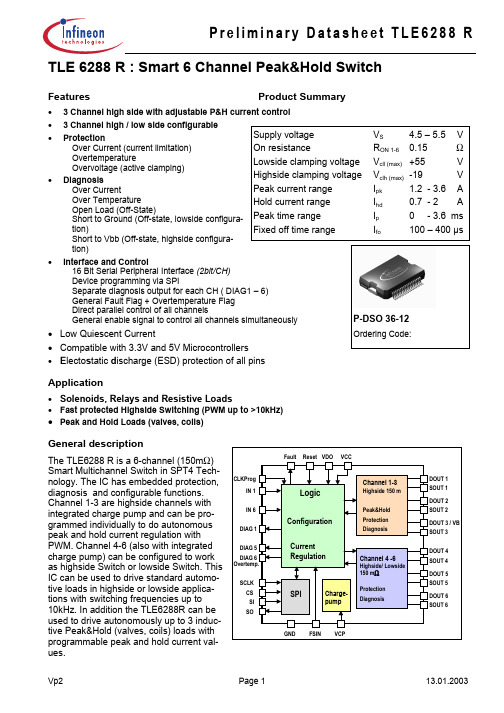
• 3 Channel high / low side configurable
• Protection
Supply voltage
VS
4.5 – 5.5 V
Over Current (current limitation) Overtemperature Overvoltage (active clamping)
Current Regulation
Channel 4 -6
Highside/ Lowside
150 mΩ
SPI
Charge- Protection
pump
Diagnosis
GND FSIN VCP
DOUT 1 SOUT 1 DOUT 2 SOUT 2 DOUT 3 / VB SOUT 3
DOUT 4 SOUT 4 DOUT 5 SOUT 5 DOUT 6 SOUT 6
DOUT 2 SOUT 2
DOUT 1 SOUT 1
DOUT 4 SOUT 4
DOUT 5 SOUT 5
DOUT 6 SOUT 6
FSIN
GND
VCP
Vp2
Page 2
13.01.2003
元器件交易网
Preliminary Datasheet TLE6288 R
2. Functional description
Channel 4..6: Either High or Low Side Drive is configurable (by SPI) Open load detection and switch bypassed detection can be deactivated by SPI
Vp2
Page 3
TLP628中文资料

TLP628,TLP628−2,TLP628−4
TOSHIBA Photocoupler GaAs Ired & Photo−Transistor
TLP628,TLP628−2,TLP628−4
Programmable Controllers DC−Output Module Telecommunication
0.1
∆VF/∆Ta – IF
0.3 0.5 1
3 5 10
Forward current IF (mA)
30 50
Pulse forward current IFP (mA)
IFP – VFP
1000 Pulse width ≤ 100µs
500 Repetitive 300 Frequency = 100 Hz
Characteristic Rise time Fall time Turn-on time Turn-off time Turn-on time Storage time Turn-off time
Fig. 1 Switching time test circuit
IF
Symbol
tr tf ton toff tON ts tOFF
―
―
200
V
―
16
25
mA
―
―
10
mA
-25
―
85
°C
2
2002-09-25
元器件交易网 Individual Electrical Characteristics (Ta = 25°C)
TLP628,TLP628−2,TLP628−4
LE D
Characteristic Forward voltage Reverse current Capacitance Collector-emitter breakdown voltage Emitter-collector breakdown voltage
威尔指纹消费机使用说明书_龙腾锐达
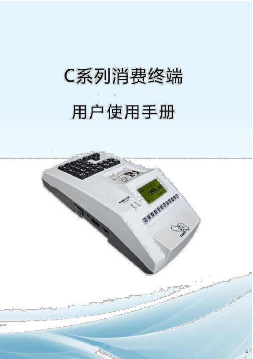
XX龙腾锐达科技XX提供XX龙腾锐达科技XX重要声明:手册中涉及到的图片信息以及功能示意图,因产品型号不同,可能与实际产品有所出入,请以实物为准。
随着产品的更新换代或升级,本手册内容将会做相应的修改,公司保留对本手册的内容进行修改的权利,恕不另行通知。
本手册属于公司,未经许可不得以任何形式和手段复制或抄袭本手册内容。
衷心感谢您选用消费终端,为保持该设备处于最佳状态,延长使用寿命,在使用前,请仔细阅读本手册。
1)遵守标注在设备上的所有警示;2)远离容易引起电磁干扰或易产生静电的环境;3)使用随机配备的电源适配器和电池;4)不要与大功率或容易引起电压波动的电器设备使用同一交流电源插座;5)避免在阳光直射、靠近热源、油烟、多尘或有腐蚀性气体的地方使用;6)如有液体洒落到机体上,请及时切断电源,并用干布擦拭干净;7)请勿将其它物体从外壳孔隙推入机体内,防止触电或引起短路;8)定期清洁设备外观。
清洁前,关闭电源开关,拔下电源插头,使用微湿的柔软布料擦拭;9)妥善放置电源适配器及电源线,防止电源线被踩踏、拉扯,造成机具跌落损坏;10) 每次开机后请检查时钟是否准确,若出现较大偏差(如超过5 分钟),需校正时间后才能使用,否则可能会造成数据混乱;11)若长期不使用,请清洁机具,保持机具整洁及干燥,将机具、配件、用户手册等重新放回原包装箱内,在通风干燥的环境中保存。
12)请勿自行拆装本产品,以防止损坏机器、丢失数据、触电或产生其它危险。
如需检修请联系服务商;13)使用过程中,如出现其它异常情况,请详细记录当前设备状态,并与服务商联系。
目录1.前言 ..........................................................................................................................................11.1 产品特点........................................................................................................................ 12. 1.2用户对象........................................................................................................................3 产品型号..................................................................................................................................4 3. 产品参数..................................................................................................................................5 4.设备外观及接口说..............................................................................................................明7 4.1 设备外观........................................................................................................................ 7 4.2 接口说明........................................................................................................................ 8 4.3键盘布局及说明 (8)4.3.1操作员键盘.............................................................................................................85.4.3.2客户键盘...............................................................................................................10 产品安装................................................................................................................................115.1 准备工作...................................................................................................................... 116.5.2使用向导......................................................................................................................12 功能介绍................................................................................................................................13 6.1 待机界面...................................................................................................................... 13 6.2功能键说明..................................................................................................................14 6.2.1 F1(管理)........................................................................................................ 14 6.2.2 F2(模式)........................................................................................................ 14 6.2.3 F3(查询)........................................................................................................ 18 6.2.4 F4(结算)........................................................................................................ 20 6.2.5 F5(撤销).. (21)6.2.6 F6(锁定)........................................................................................................22 6.3其他功能...................................................................................................................... 22 6.3.1余额查询功能.......................................................................................................226.3.2 修改卡号密码......................................................................................................23 6.4菜单说明......................................................................................................................24 6.4.1 网络设置............................................................................................................ 24 6.4.2 查询............................................................................................................ 25 6.4.3 卡号管理............................................................................................................ 26 6.4.4 消费管理............................................................................................................ 26 6.4.5 磁盘操作............................................................................................................ 28 6.4.6 常用设置............................................................................................................ 28 6.4.7 系统维护 (29)6.4.8 出厂设置............................................................................................................31 附录一:名词解释................................................................................................................................32附录二:系统提示及处理............................................................................................................措施36附录三:FAQ........................................................................................................................................38设备开机不启动............................................................................................................................38按键无反应....................................................................................................................................38 刷卡无反应....................................................................................................................................39 刷卡提“示无此卡号”................................................................................................................39 终端设备频繁重........................................................................................................................启 40 如何删除终端数........................................................................................................................据 40 通过网络不能传输数................................................................................................................据40 不能识别U 盘 ...............................................................................................................................41U 盘操作不成功............................................................................................................................41 设备无法联机................................................................................................................................42 U 盘升级方法................................................................................................................................42repair 方式软件升级.....................................................................................................................42iv1.前言 ..........................................................................................................................................11.1 产品特点........................................................................................................................ 12. 1.2用户对象........................................................................................................................3 产品型号..................................................................................................................................4 3. 产品参数..................................................................................................................................5 4.设备外观及接口说..............................................................................................................明7 4.1 设备外观........................................................................................................................ 7 4.2 接口说明........................................................................................................................ 8 4.3键盘布局及说明 (8)4.3.1操作员键盘.............................................................................................................85.4.3.2客户键盘...............................................................................................................10 产品安装................................................................................................................................115.1 准备工作...................................................................................................................... 116.5.2使用向导......................................................................................................................12 功能介绍................................................................................................................................13 6.1 待机界面...................................................................................................................... 13 6.2功能键说明..................................................................................................................14 6.2.1 F1(管理)........................................................................................................ 14 6.2.2 F2(模式)........................................................................................................ 14 6.2.3 F3(查询)........................................................................................................ 18 6.2.4 F4(结算)........................................................................................................ 20 6.2.5 F5(撤销).. (21)6.2.6 F6(锁定)........................................................................................................22 6.3其他功能...................................................................................................................... 22 6.3.1余额查询功能.......................................................................................................226.3.2 修改卡号密码......................................................................................................23 6.4菜单说明......................................................................................................................24 6.4.1 网络设置............................................................................................................ 24 6.4.2 查询............................................................................................................ 25 6.4.3 卡号管理............................................................................................................ 26 6.4.4 消费管理............................................................................................................ 26 6.4.5 磁盘操作............................................................................................................ 28 6.4.6 常用设置............................................................................................................ 28 6.4.7 系统维护 (29)6.4.8 出厂设置............................................................................................................31 附录一:名词解释................................................................................................................................32附录二:系统提示及处理............................................................................................................措施36附录三:FAQ........................................................................................................................................38设备开机不启动............................................................................................................................38按键无反应....................................................................................................................................38 刷卡无反应....................................................................................................................................39 刷卡提“示无此卡号”................................................................................................................39 终端设备频繁重........................................................................................................................启 40 如何删除终端数........................................................................................................................据 40 通过网络不能传输数................................................................................................................据40 不能识别U 盘 ...............................................................................................................................41U 盘操作不成功............................................................................................................................41 设备无法联机................................................................................................................................42 U 盘升级方法................................................................................................................................42repair 方式软件升级.....................................................................................................................421.前言 ..........................................................................................................................................11.1 产品特点........................................................................................................................ 12. 1.2用户对象........................................................................................................................3 产品型号..................................................................................................................................4 3. 产品参数..................................................................................................................................5 4.设备外观及接口说..............................................................................................................明7 4.1 设备外观........................................................................................................................ 7 4.2 接口说明........................................................................................................................ 8 4.3键盘布局及说明 (8)4.3.1操作员键盘.............................................................................................................85.4.3.2客户键盘...............................................................................................................10 产品安装................................................................................................................................115.1 准备工作...................................................................................................................... 116.5.2使用向导......................................................................................................................12 功能介绍................................................................................................................................13 6.1 待机界面...................................................................................................................... 13 6.2功能键说明..................................................................................................................14 6.2.1 F1(管理)........................................................................................................ 14 6.2.2 F2(模式)........................................................................................................ 14 6.2.3 F3(查询)........................................................................................................ 18 6.2.4 F4(结算)........................................................................................................ 20 6.2.5 F5(撤销).. (21)6.2.6 F6(锁定)........................................................................................................22 6.3其他功能...................................................................................................................... 22 6.3.1余额查询功能.......................................................................................................226.3.2 修改卡号密码......................................................................................................23 6.4菜单说明......................................................................................................................24 6.4.1 网络设置............................................................................................................ 24 6.4.2 查询............................................................................................................ 25 6.4.3 卡号管理............................................................................................................ 26 6.4.4 消费管理............................................................................................................ 26 6.4.5 磁盘操作............................................................................................................ 28 6.4.6 常用设置............................................................................................................ 28 6.4.7 系统维护 (29)6.4.8 出厂设置............................................................................................................31 附录一:名词解释................................................................................................................................32附录二:系统提示及处理............................................................................................................措施36附录三:FAQ........................................................................................................................................38设备开机不启动............................................................................................................................38按键无反应....................................................................................................................................38 刷卡无反应....................................................................................................................................39 刷卡提“示无此卡号”................................................................................................................39 终端设备频繁重........................................................................................................................启 40 如何删除终端数........................................................................................................................据 40 通过网络不能传输数................................................................................................................据40 不能识别U 盘 ...............................................................................................................................41U 盘操作不成功............................................................................................................................41 设备无法联机................................................................................................................................42 U 盘升级方法................................................................................................................................42repair 方式软件升级.....................................................................................................................421.前言 ..........................................................................................................................................11.1 产品特点........................................................................................................................ 12. 1.2用户对象........................................................................................................................3 产品型号..................................................................................................................................4 3. 产品参数..................................................................................................................................5 4.设备外观及接口说..............................................................................................................明7 4.1 设备外观........................................................................................................................ 7 4.2 接口说明........................................................................................................................ 8 4.3键盘布局及说明 (8)4.3.1操作员键盘.............................................................................................................85.4.3.2客户键盘...............................................................................................................10 产品安装................................................................................................................................115.1 准备工作...................................................................................................................... 116.5.2使用向导......................................................................................................................12 功能介绍................................................................................................................................13 6.1 待机界面...................................................................................................................... 13 6.2功能键说明..................................................................................................................14 6.2.1 F1(管理)........................................................................................................ 14 6.2.2 F2(模式)........................................................................................................ 14 6.2.3 F3(查询)........................................................................................................ 18 6.2.4 F4(结算)........................................................................................................ 20 6.2.5 F5(撤销).. (21)6.2.6 F6(锁定)........................................................................................................22 6.3其他功能...................................................................................................................... 22 6.3.1余额查询功能.......................................................................................................226.3.2 修改卡号密码......................................................................................................23 6.4菜单说明......................................................................................................................24 6.4.1 网络设置............................................................................................................ 24 6.4.2 查询............................................................................................................ 25 6.4.3 卡号管理............................................................................................................ 26 6.4.4 消费管理............................................................................................................ 26 6.4.5 磁盘操作............................................................................................................ 28 6.4.6 常用设置............................................................................................................ 28 6.4.7 系统维护 (29)6.4.8 出厂设置............................................................................................................31 附录一:名词解释................................................................................................................................32附录二:系统提示及处理............................................................................................................措施36附录三:FAQ........................................................................................................................................38设备开机不启动............................................................................................................................38按键无反应....................................................................................................................................38 刷卡无反应....................................................................................................................................39 刷卡提“示无此卡号”................................................................................................................39 终端设备频繁重........................................................................................................................启 40 如何删除终端数........................................................................................................................据 40 通过网络不能传输数................................................................................................................据40 不能识别U 盘 ...............................................................................................................................41U 盘操作不成功............................................................................................................................41 设备无法联机................................................................................................................................42 U 盘升级方法................................................................................................................................42repair 方式软件升级.....................................................................................................................421.前言 ..........................................................................................................................................11.1 产品特点........................................................................................................................ 12. 1.2用户对象........................................................................................................................3 产品型号..................................................................................................................................4 3. 产品参数..................................................................................................................................5 4.设备外观及接口说..............................................................................................................明7 4.1 设备外观........................................................................................................................ 7 4.2 接口说明........................................................................................................................ 8 4.3键盘布局及说明 (8)4.3.1操作员键盘.............................................................................................................85.4.3.2客户键盘...............................................................................................................10 产品安装................................................................................................................................115.1 准备工作...................................................................................................................... 116.5.2使用向导......................................................................................................................12 功能介绍................................................................................................................................13 6.1 待机界面...................................................................................................................... 13 6.2功能键说明..................................................................................................................14 6.2.1 F1(管理)........................................................................................................ 14 6.2.2 F2(模式)........................................................................................................ 14 6.2.3 F3(查询)........................................................................................................ 18 6.2.4 F4(结算)........................................................................................................ 20 6.2.5 F5(撤销).. (21)6.2.6 F6(锁定)........................................................................................................22 6.3其他功能...................................................................................................................... 22 6.3.1余额查询功能.......................................................................................................226.3.2 修改卡号密码......................................................................................................23 6.4菜单说明......................................................................................................................24 6.4.1 网络设置............................................................................................................ 24 6.4.2 查询............................................................................................................ 25 6.4.3 卡号管理............................................................................................................ 26 6.4.4 消费管理............................................................................................................ 26 6.4.5 磁盘操作............................................................................................................ 28 6.4.6 常用设置............................................................................................................ 28 6.4.7 系统维护 (29)6.4.8 出厂设置............................................................................................................31 附录一:名词解释................................................................................................................................32附录二:系统提示及处理............................................................................................................措施36附录三:FAQ........................................................................................................................................38设备开机不启动............................................................................................................................38按键无反应....................................................................................................................................38 刷卡无反应....................................................................................................................................39 刷卡提“示无此卡号”................................................................................................................39 终端设备频繁重........................................................................................................................启 40 如何删除终端数........................................................................................................................据 40 通过网络不能传输数................................................................................................................据40 不能识别U 盘 ...............................................................................................................................41U 盘操作不成功............................................................................................................................41 设备无法联机................................................................................................................................42 U 盘升级方法................................................................................................................................42repair 方式软件升级.....................................................................................................................42。
无线转2路4-20mA模块
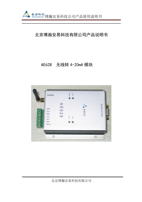
北京博瀚安易科技有限公司产品说明书AE628 无线转4-20mA模块北京博瀚安易科技有限公司一、概述无线转4-20mA模块,主要与本公司生产的无线温度变送器,无线压力变送器,无线流量计及无线密度仪,4-20mA转无线模块等无线发射端产品相配套的,将发射端的无线信号接收后,进行变送、转换、传输、运算,转换成需要的4-20mA信号。
与我司发射端的产品一起完成信号的传输工作。
二、功能特点●将我司的无线压力、温度、流量、液(物)位、密度等无线产品发射的无线数据接收,并转换成4-20mA输出;●无线输入●AO1、GND,AO2、GND为两路4-20mA输出;●通过RS232接口可以设定各种参数;RS232通道协议为MODBUS协议●RS232和4-20mA同步输出接收数据●体积小●性价比高●技术咨询QQ:583367295三、技术参数●供电电压:24VDC±10%●输入:无线信号●无线频率:433MHZ●无线增益:10dbm●无线距离:300米/500米(视距)●输出:两路4-20mA输出,RS232/RS485●负载能力:400欧●有线协议:MODBUS协议●型号:AE628●环境温度:-40℃~+85℃●环境湿度:5%~95%,无结露●振动:≤10g,f≤55Hz,振幅≤0.5mm●接地 :在电磁干扰大的地区,应将变送器和电缆屏蔽层良好接地四、安装及接线结构1、版面示意图2、接口说明2.1电源接口PGND :大地,可以不接。
VCC:24V+GND:24V-2.2 RS232/RS485接口RS232 接口/RS485接口2.3传感器接口AO1,GND :第1路接入。
AO1,为4-20mA的电流输入口。
GND为电流回路输出口。
AO2,GND :第2路接入。
AO2,为4-20mA的电流输入口。
GND为电流回路输出口。
2.3 运行指示2.3.1 Link1、Link2备用。
2.3.2 Power灯为电源指示灯,系统上电后,系统正常运行亮灯。
AWT6332RM27Q7中文资料
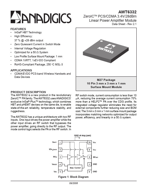
AWT6332ZeroIC TM PCS/CDMA 3.4V/28dBmLinear Power Amplifier ModuleData Sheet - Rev 2.1FEATURES• InGaP HBT Technology • High Efficiency:37 % @ +28 dBm output• Zero Quiescent Current in Switch Mode • Internal Voltage Regulation • Optimized for a 50 Ω System• Low Profile Surface Mount Package: 1 mm • CDMA 1XRTT, 1xEV-DO Compliant • RoHS-Compliant Package, 250 o C MSL-3APPLICATIONS• CDMA/EVDO PCS-band Wireless Handsets and Data DevicesPRODUCT DESCRIPTIONThe AWT6332 is a new product in the revolutionary ZeroIC™ PA family. The AWT6332 uses ANADIGICS’ exclusive InGaP-Plus™ technology, which combines HBT and pHEMT devices on the same die, to enable state-of-the-art reliability, temperature stability, and ruggedness.The AWT6332 has a unique architecture with two RF inputs. One input drives the power amplifier while the other input drives an RF switch that bypasses the power amplifier, going directly to the RF output. The mode control logic selects the PA or the RF switch. InFigure 1: Block DiagramRF switch mode, current consumption is less than 10 A, reducing the average current consumption 70% more than a HELP2™ PA over the CDG profile. Its integrated voltage regulator eliminates the need for external components further reducing size and BOM cost. The 3 mm x 3 mm x 1 mm surface mount package incorporates matching networks optimized for output power, efficiency, and linearity in a 50system.元器件交易网元器件交易网AWT6332Figure 2: Pinout (X-ray Top View)元器件交易网AWT6332ELECTRICAL CHARACTERISTICSStresses in excess of the absolute ratings may cause permanent damage.Functional operation is not implied under these conditions. Exposureto absolute ratings for extended periods of time may adversely affectreliability.over the conditions defined in the electrical specifications.Notes:(1) For operation at V CC = +3.2 V, P OUT is derated by 0.5 dB.元器件交易网AWT6332Table 4: Electrical Specifications - CDMA Operation (IS-95 Modulation)Notes:(1) PAE and ACP limit applies at 1880 MHz (IS-95 modulation).AWT6332APPLICATION INFORMATIONTo ensure proper performance, refer to all related Application Notes on the ANADIGICS web site: Shutdown ModeThe power amplifier may be placed in a shutdown mode by applying a logic low levels (see Operating Ranges table) to both the V EN and V MODE voltages.Power ModesThe power amplifier may be placed in either a Low Power mode or a High Power mode by applying the appropriate logic level (see Operating Ranges table) to the V MODE voltage. The Power Control table lists the recommended modes of operation for various applications.Figure 3: Application Circuit元器件交易网AWT6332Figure 4: M27 Package Outline - 10 Pin 3 mm x 3 mm x 1 mm Surface Mount ModuleFigure 5: Branding Specification元器件交易网AWT6332COMPONENT PACKAGINGTable 6: Tape & Reel DimensionsFigure 6: Tape & Reel Packaging元器件交易网WARNINGANADIGICS products are not intended for use in life support appliances, devices or systems. Use of an ANADIGICS product in any such application without written consent is prohibited.IMPORTANT NOTICEANADIGICS, Inc.141 Mount Bethel RoadWarren, New Jersey 07059, U.S.A.Tel: +1 (908) 668-5000Fax: +1 (908) 668-5132URL: E-mail: Mktg@ANADIGICS, Inc. reserves the right to make changes to its products or to discontinue any product at any time without notice. The product specifications contained in Advanced Product Information sheets and Preliminary Data Sheets are subject to change prior to a product’s formal introduction. Information in Data Sheets have been carefully checked and are assumed to be reliable; however, ANADIGICS assumes no responsibilities for inaccuracies. ANADIGICS strongly urges customers to verify that the information they are using is current before placing orders.AWT6332ORDERING INFORMATION元器件交易网。
访客一体机参数表

1.1、18,可设置VIP人员,输入姓名,编号,如是V1P人员,则提示并打印VIP访客单,不需要选择被访人。
2.19、(可选功能)可直接在系统上进行身份证/IC卡/二维码直接授权门禁过闸机进出,离开刷闸机后系统自动签离、自动记录离开时间。
高端部件:采用比利时进口Me1exis原装红外探测器,精度高、性能稳定、质量可靠,为国内高端
配置。
金属材质:机壳采用金属材质,坚固耐用、不易变形或损坏。
产品特点
快速筛查:主动式采集红外温度数据,不需要人员操作,在小于1秒内快速完成测温。
非接触式测温:固定式红外温度传感器测量人体腕部或额头温度,避免测温人员与被测人员直接接触,引发交叉感染。
*1.6内置条码枪,红外自动连续扫描。
*1.7内置摄像头,CMOS传感器;帧速:120帧/秒;像素:130万。
*1.8内置热敏打印机:打印宽度:80mm,打印长度:26Ommo
1.9接口:USB2.0接口4个;TCP/IP网口1
1套
个;电话线接口2个;电源接口1个;音频输入输出接口各1个。
产品重量:净重10.65kgo
*2.4、拍摄存储功能:可抓拍现场图片并自动保存。(必须提供公安部检验报告或者省部级以上国家权威机构的证明文件)
2.5、登记功能:可采集访客信息,输入被访问人姓名,自动调出人员数据,完善被访人信息。
*2.6、被访人信息登记:(1)被访人姓名模糊查询,输入姓名的第一个字、或首字母、手机号(或房间号、电话号码、分机号)模糊查询,系统自动带出相应的被访人信息;(2)选择被访对象,可根据单位、部门、职工职位、职工姓名、电话等条件进行查询。
2.20、(可选功能)微信预约的访客登记时可扫描二维码通行证,系统自动带出预约信息进行快速登记。(可定制访客机内含二维码扫描器)
卡特(Cat) PM820、PM822和PM825凝胶机械拉拔机说明文件

Cat® C18 ACERT™ EngineGross Power (ISO 14396)563 kW 755 hp Operating WeightPM820 36 130 kg 79,630 lb PM822 36 700 kg 80,887 lb PM825 37 500 kg 82,650 lb Cutting DimensionsWidth - PM820 2010 mm 79 in Width - PM822 2235 mm 88 in Width - PM825 2505 mm 98.8 in Maximum Cutting Depth 330 mm 13 inPM820, PM822 and PM825 Cold Planers2CONTENTSIntroduction. . . . . . . . . . . . . . . . . . . . . . . . . . . . . . . . . . 2, 3Machine Feature Overview ....................4, 5Powertrain, Undercarriage ....................6, 7Operating Environment ........................8, 9Cutting System .............................10, 11Cat Grade Control Option ....................12, 13Material Collection System ..................14, 15Optional Equipment .........................16, 17Service and Reliability. . . . . . . . . . . . . . . . . . . . . . . 18, 19Cutting Bits ...................................20Cat Diamond Bits ..............................21Specifications ..............................22, 2323THE HIGH POWER HALF-LANE MILLING MACHINES YOU HAVE BEEN WAITING FORCat ® PM820, PM822 and PM825 cold planers are the product of years of study, tinkering, rethinking. Every system andcomponent has been examined, refined, optimized. The result is an advanced, world-class cold planer.The PM800 models are similar in design to their sister PM600 half lane cold planers...but they bring a lot more power, useful for the most demanding applications. The PM800 models deliver the same benefits as well: lowered operating costs and increased productivity, paired with Cat reliability and the legendary dealer support you expect from Caterpillar.The PM820, PM822 and PM825 are well equipped to deliver precision and efficient high production. Many options are available to enhance machine versatility and customize operations to suit the application, from milling highways to urban streets. Whether you are texturing the surface or milling an airport runway, there is a configuration that will meet your requirements and expectations.POWERFUL AND REFINEDPRECISION AND CONTROL WITH VERSATILITY TO SPARE.4938641011121413612457721. Cat C18 ACERT ™ Engine2. Ground Control Console3. Rear Water Fill Nozzle4. Remote Camera (option)5.Hydraulic Side Plates with Position Sensors6. Crawler Tracks with Bolt-on Pads7. Advanced Steering8. Dual Operating Consoles 9. Power Canopy (optional windscreens available, not shown)10. Dust Abatement System (option)11. High Pressure Water Spray Hose (option)12. Water Spray Control and Clean out Manifold13. LCD Touchscreen Display 14. Cat Diamond Bits (option)15. Cat Grade Control (option)515152744667891013142RUGGED POWERTRAIN SIMPLE DESIGN DELIVERS AMPLE POWER TO GROUND.C18 ACERT ENGINE– Meets regional emission standards as required:U.S. EPA Tier 4 Final / EU Stage IV– Provides a gross power of 563 kW (755 hp)– Automatic idle control function and multiple rotor speedsoptimizes output to the demand on the engine, keepingoperation smooth and efficient– High capacity cooling system keeps engine at idealtemperature for optimal fuel efficiency and lower emissions– Proven core engine design ensures reliability and quietoperation– Engine is iso-mounted to reduce noise and vibration6PROPEL SYSTEM– Robust propel system features two propel pumps and two propel circuits, diagonally opposed; each circuit drives the propel motors for two crawler tracks– Cross-flow traction control supplies dedicated hydraulic flowdiagonally across machine to the tracks that grip– Automatic Load Control senses load changes on the rotor system load and adjusts propel speed to prevent stalls and optimizeproduction7STABLE PLATFORM– Four leg posts with position sensors independently adjust and provide powered vertical movement to maintain desired height – Ride-control feature ensures smooth travel– Optional Cat Grade Control is integrated with the machine and works seamlessly to provide maximum cutting precision; system can be enhanced to full 3D milling capabilityWORRY-FREE TRACKS– Four crawler tracks based on proven Cat track design and components– Tracks automatically adjust to provide ideal tension – Track pads are easily replaceable with bolt-on designEXCELLENT MANEUVERABILITY– Four steering modes: front steer, rear steer, crab steer, coordinated steer– Advanced steering function adjusts track alignment to provide precise steering geometry and reduce pad wear – Minimum left cutting radius: 2 m (6.56 ft)– Minimum right cutting radius: PM820- 2 m (6.56 ft) PM822- 1.8 m (5.91 ft)PM825- 1.5 m (4.92 ft)The four post design offers excellent maneuverability and dependable operation to maximize versatility and production.8OPERATING ENVIRONMENT– Height-adjustable dual operating console is intuitive and comfortable– Optional power canopy can deploy or stow during machine operation; optional windscreen panels available– Touchscreen LCD display provides gauge cluster, operating information, remote camera feed, machine control anddiagnostics; optional second and third display available to provide additional gauge or machine operation/control information – Optional suspension seats reposition for optimal visibility and comfort– Lockable storage provides secure area to stow personal items – 12-volt power receptacleERGONOMIC CONTROLS– Controls comfortably positioned for easy use– Large, backlit keypads are visible in all light conditions – Durable design tested to 1 million cycles– Lockable covers provide protection from vandalismEQUIPPED FOR 24/7 OPERATION– Working areas and perimeter well lit with standard halogen lights – Displays and controls easy to see – Additional LED light options – Available balloon lighting optionsCOMFORT AND CONTROLOPERATE WITH CONFIDENCE.REAR910ROBUST ROTOR CHAMBER– Chamber optimizes material flow to promote thorough clean-out – Thicker steel in areas exposed to high abrasion enhances durability– Side plates are hydraulically adjustable with position-sensing cylinders, can be used as an averaging ski– Hydraulically adjustable moldboard applies optimal down-pressure to keep material contained for clean out and minimize required sweepingANTI-SLAB DEVICE– Helps to optimize sizing and gradation – Protects collecting conveyor– Prevents blockage in the discharge openingTHE VERSATILITY YOU NEED– Two available cutting widths; – Cutting depth to 330 mm (13 in)– Enhanced clearance for flush cutting– Three rotor speeds, electronically selectable during operation – High production and fine milling drums available – Optional Cat Grade Control keeps machine on targetCUTTING SYSTEMEFFICIENT AND DEPENDABLE, AS IT SHOULD BE.11ADVANCED AUTOMATED FEATURES– Automatic Load Control senses load changes on the rotor and adjusts propel speed to prevent stalls and optimize production– Automatic plunge-cut feature ensures precise, repeatable starting cuts and reduces wear on machine (requires Cat Grade Control option)– Ramp-in, Ramp-out cutting capability (requires Cat Grade Control option)– Jump hold feature assists to clear obstaclesROTOR DRIVE SYSTEM– Driven by two 6-rib high-tensile belts– Automatic belt tensioning to reduce slippage – Heavy-duty dry clutchHIGH PRODUCTION ROTORS– 2.0 m (79 in), 2.2 m (88 in) or 2.5 (98.6 in) cutting widths– Cutting bits held in exclusive conical quick-release tool holders and arranged in a triple-wrap flight pattern– Large, replaceable carbide-faced loading paddles effectively move milled material onto collecting conveyor– Standard 15 mm (0.6 in) tool tip spacing is optimal for high production and reduced wear– Triple tree tool arrangement on rotor ends reduces wear on rotor when maneuvering in the cut– Cat MasterGrade™ premium carbide bits available – Optional Cat Diamond Bits provide cutting life up to 80 times longer than conventional carbide bits, decreasing overall fuel consumption and reducing machine wear12INTEGRATED DESIGN– System communicates directly with position-sensing hydraulic cylinders, slope sensors and processors to ensure optimalprecisionCONTROL BOXES– LCD color touchscreen display with soft keys is durable andvisible in all light conditions– Intuitive interface is easy to understand and use– Supports multiple languages– Control boxes and sensors can be repositioned withoutreconfiguring settings– Full control over grade and slope can be attained from anycontrol boxCAT GRADE CONTROLEASY TO USE; HIGH PRECISION.BLUE: Averaged readings RED: Discarded readings1REFERENCE VERSATILITY1. Sonic Mounting Point2. Control Box Mounting Point3. Position-sensing Independently Controlled Side Plates4. Optional Position-sensing Hydraulically Controlled Inboard Ski2234SYSTEM VERSATILITY– System can utilize various references including sonics, contact sensors, position sensing hydraulic cylinders, wire rope sensors – Can be enhanced for full 3D operation– Sensors can be positioned in multiple inboard or external locations around the machineSONIC SENSORS– Sensor units feature five ceramic transducers– System discards the highest and lowest readings and averages remaining three for a true average– Each unit equipped with temperature sensor that compensates for fluctuations due to temperature change– Durable construction outlasts foil transducer design1113Each sensor has five transducers; the high and low readings are discarded and the remaining three are averaged for a true average reading.The high-capacity conveyors provide efficient removal of milled material and dust with outstanding discharge control.COLLECTING CONVEYOR– A wide opening and seamless 850 mm (33.5 in) wide belt efficiently clears rotor chamber– Reversible for easy clean out– Optional grease tensioner provides easy adjustment of belt alignment and tension WATER SPRAY SYSTEM– Water spray system provides lubrication and cools bits whilehelping to control dust– Spray system fed by 3400 L (898 gal) onboard tank; tank can be filled from top deck ports, rear fill valve, side fill valve or optional refill pump– Optional additional water spray system provides maximumlubrication, cooling and dust suppression– Onboard winterization system utilizes compressed air to purge water lines1415LOADING CONVEYOR– Aluminum covers and vinyl side panels reduce spillage and help control dust– Seamless 850 mm (33.5 in) wide belt provides heavy duty, high speed discharge– Variable belt speed optimizes speed to material type and production rate– Reversible for easy clean out– “Boost” feature provides a temporary surge in belt speed to help precisely place material– Loading conveyor folds to reduce length for transport– Loading conveyor swings 60 degrees from center position to the left or right60˚60˚OPTIONAL DUST ABATEMENT SYSTEM– Vacuum system ports to collecting conveyor housing and transition between collecting and loading conveyor to remove airborne particles– Augments dust suppression provided by water spray system – Discharges collected dust into the loading conveyor to facilitate removal from working area around machine – Maximizes dust removal capability when used with water spray system and optional additional water spray systemCAT GRADE AND SLOPE CONTROLSystem is integrated with the machine for maximum precision POWER SUN CANOPYDeploys or stows hydraulicallyWINDSCREENS FOR POWER SUN CANOPYCAT DIAMOND BITSLasts up to 80 times longer than conventional carbide bits ADDITIONAL LCD TOUCHSCREEN DISPLAYFor use to monitor machine functionsPRODUCT LINK, ADDITIONAL CONFIGURATIONSKeep track of your machine health, location or fleet use ADDITIONAL WATER SPRAY SYSTEMSecond system augments lubrication, bit cooling and dust suppression capabilities of the standard systemINBOARD AVERAGING SKIHydraulically controlled ski provides inboard reference for grade control systemROTOR TURNING DEVICEAssists with turning rotor during rotor serviceDUST ABATEMENT SYSTEMVacuum system ports to the transition area between the rotor chamber and the collecting conveyor as well as the transition between the collecting conveyor and the loading conveyor; dust is removed and expelled within the loading conveyor, where is it discharged with the milled materialREMOTE CAMERA, LOADING CONVEYORMounts to the discharge end of the loading conveyor; provides enhanced view of discharge loading REMOTE CAMERA, REARMounts to the rear of machine; provides enhanced view of area behind the machineREMOTE CAMERA, MAGNETIC MOUNTMounts magnetically to various locations; up to two magnetic cameras can be usedSUSPENSION SEATAdjustable seats installed on operator’s platformBIT BUCKET TRAYSTrays mount to rear crawlers and provide convenient storage for bit bucketsHIGH PRESSURE WASHDOWN SYSTEMHigh pressure hose and spray wand connect to onboard water tank to deliver high pressure water spray for convenient clean up WATER TANK TRANSFER PUMPWater pump provides additional options to fill onboard water tank FUEL TRANSFER PUMPFuel pump provides additional options to fill fuel tank WARNING BEACON, FIXEDAmber warning beacon mounts to one of two fixed locations on loading conveyor or rear of machineWARNING BEACON, MAGNETIC MOUNTAmber warning beacon can be magnetically mounted in multiple locations on the machineCOMMISSIONING SUPPORTCat technician provides machine introduction and training to key personnelOPTIONAL EQUIPMENT OPTIMIZE VERSATILITY, PRODUCTIVITY, COMFORT.161.Power Sun Canopy2. Inboard Averaging Ski3.Dust Abatement System4. Remote Camera, Loading Conveyor5.Remote Camera, Magnetic Mount6.Bit Bucket Trays7.High Pressure Washdown System8. Water Tank Transfer Pump3861245717EASY SERVICE DESIGNED RIGHT IN.Outstanding access to critical components and systems makes service and maintenance easier and faster. That keeps your machine where you need it: on the job.LARGE ACCESS DOORS AND PANELS– Designed to facilitate efficient service, reducing labor costs and service time– Quick and easy maintenance– Accessible pumps and components– Power hood opens to allow walk-in access– Visual indicators simplify routine service checks18HYDRAULIC SYSTEM– Manual overrides simplify troubleshooting by eliminatingfunctioning systems– Hydraulic hoses are cleanly routed and clamped for long-term reliability– Exposed hoses are wrapped in nylon sleeves for protectionagainst abrasion– Pressure test ports and oil sampling ports simplify hydraulicsystem diagnosisELECTRICAL SYSTEM– 24-volt system with 100 amp alternator– Color-coded and numbered electrical wiring simplifiestroubleshooting– Harnesses are wrapped in abrasion-resistant nylon braid ELECTRONIC CONTROL MODULES (ECM)– Monitors machine systems to ensure proper function andprecision– Provides warning indications via LCD touchscreen display when machine performance is substandard– Provides diagnostic information TELEMATICS: PRODUCT LINK™– Maximize up-time– Automatic machine location– Hour updates– Diagnostic codes– Schedule service at convenient times– Optional configurations availableLONG SERVICE INTERVALS– 500 hour engine oil service interval– 3,000 hour hydraulic oil service interval without oil sampling;6,000 hours with oil samplingACCESSORY DRIVE SYSTEM– Provides full operational control of auxiliary machine functions to enable assisted machine movement during maintenance or service– Facilitates assisted relocation of machine from live construction area to service area during emergency situations19Pallet ConcreteAsphalt or Asphalt off ConcreteAsphaltShallow 25 - 50 mm (1” - 2”)Moderate 75 - 125 mm (3” - 5”)Deep 150 mm (6” o r more)Puller Tool351-267844444292-510344444349-49464444316-23274444350-71994444Ø19.4Ø19.822182117217PROVEN BENEFITSMore efficiency, more productivity, lower fuel consumption and less wear on the machine. It all adds up to more profitability and growth for your company.– Last up to 80x longer than carbide tips, keeping crews more productive, month after month– Assure faster project completions– Provide you with a significant bidding advantage– Virtually eliminate labor costs for pick changes; eliminate unplanned, unproductive interruptions– Deliver proven fuel savings per ton of production– Enable faster milling speeds and increased productivity– Eliminate costly bit inventory, and the handling that goes with it– Require no rotation, crucial because half of carbide failures result when tools fail to turn– Create less vibration, increasing the life of planetaries, drive shafts, stub shafts, bearings and other parts and components– Increase track-pad life because the machine does not work as hard– Deliver a dramatically improved return on your mill investment through increased engagement– Extend life of moldboards through a consistent pattern; protect welded-on base blocks—and ultimately the drum Average life and exact tonnage is impacted by local aggregate and operating technique. Diamond Asphalt Bits last up to 45x the life of standard carbide bits and Diamond Extended Life Bits last up to 80x the life of standard carbide bits.STAY SHARP UP TO 80X CONVENTIONAL CARBIDE.2122SPECIFICATIONSHH23Weights shown are approximate and include:• Operating weights include coolants, lubricants, full fuel tank, full water tank and 75 kg (165 lb) operator.• Transport weights include coolants, lubricants, 50% full fuel tank and empty water tank.WeightPM820Operating weight 36 130 kg 79,630 lb Transport weight 32 230 kg71,035 lbPM822Operating weight 36 700 kg 80,887 lb Transport weight 32 800 kg 72,290 lbPM825Operating weight 37 500 kg 82,650 lb Transport weight33 600 kg 74,054 lbFuel Tank1108 L 288.1 gal Cooling System 104 L 27.5 gal Engine Oil 65 L 16.9 gal Hydraulic Oil 113 L 29.4 gal Water Tank3400 L898 galService Refill CapacitiesCat C18 ACERT Engine Gross power - ISO 14396 563 kW 755 hp Global emissions US EPA Tier 4 Final / EU Stage IVor Tier 3 / Stage IIIA / China Stage III equivalentOperating speed100 m/min 328 ft/min Maximum travel speed 5.9 km/h 3.7 mphPowertrainPM820 Milling Width2010 mm 79.1 in Number of Bits 170PM822 Milling Width 2235 mm 88 in Number of Bits 185PM825 Milling Width 2505 mm 98.6 in Number of Bits203Maximum Cutting Depth 330 mm 13 in Rotor Speeds100 / 109 / 118 rpmCutting SystemPower CanopyWindscreens for Power Canopy Inboard Averaging Ski CE CertificateAdditional Water Spray System Water Tank Transfer Pump Fuel Transfer Pump Dust Abatement System Cat Grade ControlRemote Camera (Front, Rear, or Magnet Mount)Product Link (optional configuration)Air-ride Operator’s Seats Drum Rotating Device Cat Diamond Bits Bit Bucket TraysMachine Commissioning SupportOptional EquipmentSPECIFICATIONSA Overall length, conveyor up14.52 m 47.62 ft B Maximum machine width - PM820, PM822 2.83 m 9.27 ft Maximum machine width - PM825 3.14 m 10.03 ft C Cutting width - PM820 2010 mm 79.1 in Cutting width - PM822 2235 mm 88 in Cutting width - PM8252505 mm 98.6 in D Maximum height, raised conveyor 5.23 m 17.17 ft E Height to optional canopy4.05 m 13.29 ft F Height, no canopy (canopy down) 3.00 m 9.84 ft G Maximum truck clearance 4.86 m 15.95 ft HConveyor swing± 60˚ from centerOperating DimensionsI Transport length12.43 m 40.79 ft J Transport width - PM820 2.50 m 8.2 ft Transport width - PM822 2.70 m 8.83 ft Transport width - PM825 3.01 m 9.88 ft K Length, track to track 6.69 m 21.95 ft L Length of base machine 8.33 m 27.33 ft FTransport height3.00 m 9.84 ftShipping DimensionsPM820, PM822 AND PM825 Cold Planers。
A6281EESTR-T;中文规格书,Datasheet资料
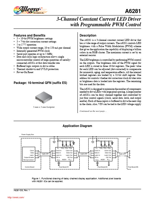
A6281bus, thus eliminating the need for a separate chip supply bus or an external regulator.Applications include:▪ Colored, large-character LED signs▪ Scrolling, colored marquees ▪ Architectural lighting ▪ High intensity monochrome displays▪ Large video and graphic displays The A6281 is supplied in a 3 mm × 3 mm 16-terminal QFN (suffix ‘ES’) package, with 0.75 mm nominal overall height. The package is lead (Pb) free with 100% matte-tin leadframe plating.Part Number Packing*MountingA6281EESTR-T1500 pieces/reel16 terminal QFN*Contact Allegro for additional packing options.Selection GuideAbsolute Maximum RatingsCharacteristicSymbol NotesRating Units Load Supply Voltage V IN 17V Output Voltage V OUT OUT0, OUT1, OUT2–0.5 to 17V Output Current I OUT 170mA Ground Current I GND 600mA VREG Pin V REG 6V Logic OutputsV O CO, LO, OEO, SDO 7V Logic Input Voltage Range V I CI, LI, OEI, SDI –0.3 to 7V Operating Ambient Temperature T A Range E–40 to 85ºC Maximum Junction Temperature T J (max)150ºC Storage TemperatureT stg–55 to 150ºCDescription (continued)Thermal CharacteristicsCharacteristicSymbolTest Conditions*Rating UnitsPackage Thermal ResistanceR θJA4-layer PCB based on JEDEC standard47ºC/W*For additional information, refer to the Allegro website.255075100125150Temperature (°C)P o w e r D i s s i p a t i o n , P D (m W )450040003500300025002000150010005000Power Dissipation versus Ambient TemperatureR Terminal List TableNumberName Description1REXT An external resistor at this terminal establishes maximum output current 2VREG Regulator decoupling 3LGND Logic ground4VIN Chip power supply voltage; connect to VREG externally if 4.75 V < V IN < 5.5 V 5CI Serial clock input; PWM clock if external clock is selected6OEI Output enable input; when low (active), the output drivers are enabled; when high (inactive), all output drivers are turned off (blanked)7LI Latch input terminal; serial data is latched with high-level input 8SDI Serial data input to shift register 9OUT2Sinking output terminal 10PGND Power ground 11OUT1Sinking output terminal 12OUT0Sinking output terminal13SDO Buffered serial data output after shift register 14LO Buffered latch output 15OEO Buffered output enable output 16CO Buffered clock output–PADExposed thermal pad, not internally connected; connect externally to LGND and PGND.Pin-out DrawingsFunctional Block Diagram12111091234567816151413C OO E OL O S D OC IO E IL IS D IOUT0OUT1PGND OUT2REXT VREG LGND VINPADOPERATING CHARACTERISTICS, valid at T A = 25°C, V IN = 4.75 to 17.0 V, unless otherwise notedCharacteristic Symbol Test Conditions Min.Typ.Max.Units ELECTRICAL CHARACTERISTICSQuiescent Supply Current I DD f CLKIN = 0.0 Hz–– 5.0mA Operating Supply Current I DD f CLKIN = 5 MHz––15.0mA Load Supply Voltage V IN 4.75–17VUndervoltage Lockout V IN(UV)V IN rising–– 4.5V V IN falling 3.0––VVREG Voltage Range1V REG I OUT =15 mA, V IN = 17 V 4.6– 5.4VOutput Current (any single output)I OUT R EXT = 5 kΩ, scalar = 100%135150.0165mA R EXT = 15 kΩ, scalar = 100%455157mAOutput to Output Matching Error2Err Output to output variation—all outputs on, R EXT =5 kΩ–7– 7% Output Voltage Range V DS(min) 1.0– 3.0V Load Regulation (I%Diff / ∆V DS)R EXT = 5 kΩ, V DS = 1 to 3 V–±1±3%/V Output Leakage Current I DSX V OH = 17 V–– 1.0μALogic Input Voltage V IH 2.0––V V IL––0.8VLogic Input Voltage Hysteresis All digital inputs–150–mV CI and SDI Pins Logic Input Current I IN V IN = 0 to 5 V–20–20μAInput Resistance R I OEI pin, pull-up150300600kΩLI pin, pull-down100200400kΩLogic Output Voltage V OL V IN≥ 5.0 V, I O = ±2 mA––0.4V V OH 3.8––VOutput Dot Correction Error R EXT = 5 kΩ; LSB–±1–bit PWM Oscillator f PWM–800–kHz Thermal Shutdown Temperature T JTSD Temperature increasing–165–°C Thermal Shutdown Hysteresis T Jhys–15–°C SWITCHING CHARACTERISTICSClock Hold Time t H(CLK)20––ns Data Setup Time t SU(D)20––ns Data Hold Time t H(D)20––ns Latch Setup Time3t SU(LI)20––ns Latch Hold Time t H(LI)20––ns Output Enable Set Up Time t SU(OE)40––ns Output Enable Falling to Outputs Turning OnPropagation Delay Timet P(OE)–200–ns Clock to Output Propagation Delay Time t P(OUT)External clock selected, V DS = 1.0 V, I O = 150 mA–200–ns Logic Output Fall Time t BF C OB = 50 pF, 4.5 to 0.5 V–50100ns Logic Output Rise Time t BR C OB = 50 pF, 0.5 to 4.5 V–3060nsOutput Fall Time (Turn Off)t f C OUT = 10 pF, 90% to 10% of I OUT = 10 mA–10–ns C OUT = 10 pF, 90% to 10% of I OUT = 150 mA–10–nsOutput Rise Time (Turn On)t r C OUT = 10 pF, 10% to 90% of I OUT = 10 mA–50–ns C OUT = 10 pF, 10% to 90% of I OUT = 150 mA–100–nsClock Falling Edge to Serial Data OutPropagation Delay Timet P(SDO)–50–ns Logic In to Output Propagation Delay t P(IO)LI→LO, CI→CO, OEI→OEO–50–ns Clock Out Pulse Duration t w(CLK)70100130ns Maximum Clock In Frequency f CI––6MHz 1If V IN is a 4.75 to 5.5 V supply, connect VIN to VREG externally2Err = [I O (min or max) – I O(av)] / I O(av), where I O(av) = average of 3 output current values.3In daisy-chained applications, t SU(LI) must be increased for the quantity of pixels in the chain (see Application Information section).CI(External Clock)SDI(Serial Data In)SDO(Serial Data Out)LI(Latch In)LO(Latch Out)t PWM Counter OEI(Output Enable Input)OEO(Output Enable Output)I OUT0I OUT1I OUT2Brightness Data=0Brightness Data=1Brightness Data =1022Internal Oscillator or CI (External Clock)Figure 3. PWM Counter and Output TimingFunctional DescriptionFigure 4. Functional DiagramShift RegisterThe A6281 has a 32-bit shift register that loads data through the SDI (serial data in) pin. The shift register operates by a first-in first-out (FIFO) method. The most significant bit (MSB, bit 31) is the first bit shifted in and the least significant bit (LSB, bit 0) is shifted in last. The serial data is clocked by a rising edge of the CI (clock in) pin. The SDO (serial data out) pin is updated to the state of bit 31 on the falling edge of the CI pin. This will prevent any race conditions and erroneous data that might occur while propagating information through multiple A6281s that are daisy chained together. The contents of the shift register will continue to propagate on every rising edge of the CI pin. The information in the shift register is latched on a low-to-high transition of the LI (Latch In) pin. The LI pin must be brought low before the rising edge of the next clock pulse, to avoid latching erroneous data. The latched data remains latched on a rising signal on the OEI (output enable in) pin.Output BuffersThe A6281 is designed to allow daisy chaining many A6281s together. It can pass the clock, data, latch, and output enable signals from one A6821 to the next without any loss of data due to duty cycle skewing or signal degradation.The A6821 is equipped with output buffers that allow the data signals to travel over long distances through strings of A6281s without the need for extra driving hardware. The A6281 drivesthese signals to TTL levels. Each of the A6281 inputs has a cor-responding buffered output:• CI (clock in) pin to CO (clock out) pin • LI (latch in) pin to LO (latch out) pin• OEI (output enable in) pin to OEO (output enable out) pin • SDI (serial data in) pin to SDO (serial data out) pinThe CO (clock out) pin is driven by an internal one-shot circuit. When the CI pin detects an edge rising through the input thresh-old, the one-shot circuitry drives the CO pin high for 100 ns. The CI pin input threshold has hysteresis to prevent false triggering of the CO signal. The implementation of the one-shot solution allows many A6281s to be daisy chained together with a consis-tent clock signal throughout the entire chain without degradation or loss of synchronicity to the data line. PWM Brightness ControlThe A6281 controls the intensity of each LED by pulse width modulating the current of each output. The A6281 has three10-bit brightness registers, one for each output. These brightness registers set the PWM count value at which the outputs switch off during each PWM cycle. Each 10-bit brightness register gives 1023 levels of light intensity. The duty cycle, DC, can be deter-mined by the following equation:DC = [(PWM n + 1) / 1024] ×100 (%) ,where PWM n is the PWM value greater than zero that is stored in the brightness register.RThe relationship of the PWM n value to the output duty cycle is given in the following table:PWM n Duty Cycle00/1024 (0 %)12/102423/1024. . .. . .10231024/1024 (100 %)When the brightness register is set to zero, the outputs remain off for the duration of the PWM cycle for a 0% DC. When a bright-ness register is set to 1023, the LED for that output remains on (100% DC) when OEI is active and begins the PWM cycle. The output remains on when the PWM counter rolls over and begins a new count.The PWM counter begins counting at zero and increments only when the OEI pin is held low. When the PWM counter reaches the count of 1024, the counter resets to zero and continues incrementing. The counter resets to zero on a rising edge of OEI, upon recovery from UVLO, or when powering up. Latching new data into the brightness registers will not reset the PWM counter.A free-running internal 800 kHz oscillator is the master clock for the PWM counter. A programmable clock divider frequency allows the PWM to be set at approximately at 200 kHz, 400 kHz, or 800 kHz, or the PWM can be set to count on the rising edge of the external CI signal. Bit assignments for the programmable clock divider are shown in the following table:BitsClock Mode7810400 kHz01External (count on rising edge of CI signal)11200 kHzThe total number of possible colors of an RGB pixel is over1 billion. Refer to figure 4 for the mapping of shift register bits to latches.Output Current SelectionThe overall maximum current is set by the external resistor,R EXT, connected between the REXT and LGND pins. After being set, the maximum current remains constant regardless of the LED voltage variation, supply voltage variation, temperature, or other circuit parameters. The maximum output current can be calculated using the following equation:I OUT(max)= 753.12 / R EXT.The relationship of the value selected for R EXT and I OUT is shown in figure 6.Internal Linear RegulatorThe A6281 has a built-in linear regulator. The regulator operates from a supply voltage of 5.5 to 17 V. It allows the VIN pin of the A6281 to connect to the same supply as the LEDs. This simpli-fies board design by eliminating the need for a chip supply bus and external voltage regulators. For 5 V supplies, connect VIN to VREG externally. Note: When using 5 V supplies, ensure that VIN does not exceed the absolute maximum rating of the VREG pin (6 V).The V REG pin is used by the internal linear regulator to connect to a bypass capacitor. This pin is for internal use only and is notBits 0123456789101112131415161718192021222324252627282930a31 PWM Counter 0PWM Counter 1PWM Counter 2Address “0”X bDot Correction Register 0ClockModeXDot CorrectionRegister 1X X XDot CorrectionRegister 2X ATB c ATB c Address “1”Xa Selects which word is written to: Dot Correction/Clock Mode selection or PWM counter.b X indicates “Don’t Care.”c Allegro Test Bit (ATB). Reserved for Allegro internal testing. Always set to zero (0) in the application.Figure 5. Register ConfigurationFigure 6. Output Current versus External Resistor, R EXTintended as an external power source. There should be a 1.0 μF, 10 V ceramic capacitor connected between the V REG pin and LGND. The capacitor should be located as close to the V REG pin as possible.Dot Correction ControlThe A6281 can further control the maximum output current for each output by setting the three 7-bit dot correction registers with scale data that ranges from 36.5% to 100% of the overall maximum output current that is set by the REXT resistor. This feature is useful because not every type of LED (red, green, or blue, for example) has the same level of brightness for a given current, and the brightness could be different even from LED to LED of the same type. By scaling the output currents so that all the LEDs have matched intensities, the application will have full color depth when using the PWM counters. The dot correction current can be calculated by the following equation:I OUT n = I OUT n(max) × (Scale n / 2 + 36.5) / 100Where Scale n is in the range 0 to 127, as shown in the following table:Scale I OUT/I OUT(max)(%)036.5137.0237.5. . .. . .127100Refer to figure 5 for the bit configurations for the scalar registers.The dot correction data in the shift register is latched on a rising edge of the LI pin. The dot correction data remains latched on a rising OEI signal. The default output current when the A6281 is powered-up or recovers from a UVLO is 36.5% of the current set by the R EXT resistor.Package Power DissipationThe maximum allowable package power dissipation is deter-mined as:P D(max) = (150 – T A) / RθJA .The actual package power dissipation is:P D(act) = DC0 × V DS0 × I OUT0+ DC1 × V DS1 × I OUT1+ DC2 × V DS2 × I OUT2 + V IN × I IN , where DC i is the PWM duty cycle for channel i, and I OUTi is the output current for channel i, determined by the dot correction current for that channel and REXT.When calculating power dissipation, the total number of avail-able device outputs is usually used for the worst-case situation (3 LEDs at 100% duty cycle).Thermal Shutdown (TSD)When the junction temperature of the A6281 reaches the thermal shutdown temperature threshold, T JTSD (165°C typical), the outputs will shut off until the junction temperature cools down below the recovery threshold, T JTSD –∆T J ( 15°C typical). The shift register and output latches will remain active during the TSD event. Therefore there is no need to reload the data into the output latches.Undervoltage LockoutThe A6281 includes an internal undervoltage lockout (UVLO) circuit that disables the driver outputs in the event of the logic supply voltage dropping below a minimum acceptable level. This prevents the display of erroneous information, a necessary function for some critical applications. The shift register will not shift any data in a UVLO condition. Upon recovery of the logic supply voltage and on power up, the internal shift register and all latches will be set to zero.Ballast ResistorsThe voltage on the outputs should be kept in the range 1 to 3 V. If the voltage goes below 1V, the current will begin to rolloff as the driver runs out of headroom. At V OUT above 3 V, the power dissipation may become a problem, as each output contributesV OUT × I LED of power loss in the output sink driver. Typically the power supply nominal voltage is chosen to keep the output volt-age in this range. Alternatively, series resistors can be added to dissipate the extra power and keep the output voltage within the recommended range.Application InformationTiming ConsiderationsA6281s can be used in large numbers to drive many LEDs with the control signals connected serially together using short cables between each pixel (see figure 8). Because the clock negative edge drives the data to the SDO pin, and the CO pin is driven by a 100 ns one-shot function, the clock and data signals remain synchronized with each other from the first pixel in the chain to the last.After all of the data is written to each A6281 in the chain, the data is latched into each A6281 via a low-to-high transition on the LI pin. The LO pin of pixel #1 drives the LI pin of pixel #2, and so on down the chain. These signals are buffered and are driven asynchronously relative to the CI and SDI pins. Therefore the mismatch in delays between CO and LO must be taken into consideration.Although the mismatches in delays are quite small, they must be considered when creating the timing pattern for driving the chain. The key parameter is the setup time from the last CI clock rising edge to the rising edge of LI.The minimum A6281 setup time from CI to LI is 20 ns. There may be a 5 ns per pixel mismatch in the propagation delays of the CI and LI signals (the delay from CI to CO compared to the delay from LI to LO). As a rule of thumb, use a setup time, t su , at the first A6281 in the chain as calculated below:t su = 20 ns + n × 5 ns ,where n is the number of pixels in the chain.This will ensure that the setup time at the last pixel in the chain is at least 20 ns.Figure 7. Signal Delay Mismatch Timing Diagram. t su is the setup time for signals (CI to LI) applied to the first pixel in the chain. Note the difference in delay for CI(1) to CI(n ) compared to the delay for LI(1) to LI(n ). This must be compensated by increasing t su .CO(1)=CI(2)CI(1)CO(2)=CI(3)CO(n -1)=CI(n )LI (1)LO(1)=LI (2)LO(2)=LI (3)LO(n -1)=LI (n ))Applications Drawings8.5 VFigure 9. Application driving high power LEDs at 450 mA total分销商库存信息: ALLEGROA6281EESTR-T。
NOSHOK 628系列无爆内部安全锤联合传感器技术手册说明书

628 Series Intrinsically Safe Hammer Union TransmittersTechnical ManualNOSHOK 628 SeriesIntrinsically Safe Hammer Union Transmitters • Before installation, please read the entire manual.• If you do not observe the appropriate regulations, serious injuries and/or damage can occur.• Do not use the transmitter in any other way than described in these operating instructions, or protection provided by the equipment may be impaired.• Repairs done by the customer will void the warranty and approvals, and may create an explosion hazard.• DO NOT use these products as stop devices or in any other application where failure of the product could result in personal injury.• Ensure that the transmitter is only operated in accordance with the provisions as described in the following instructions.Table Of ContentsChapter 1Product Specifications (4)Installation General (5)Removal, Maintenance and Repair (6)Hazardous Location Information (7)Understanding Approval Ratings ..............................................8-9 Chapter 2Intrinsically-Safe Installation (10)Control Drawings for I.S. Applications ..................................11-12 Chapter 3Non-Incendive Installation (13)Installation Drawings for Non-Incendive Applications ..........14-15 Warranty .. (16)Product SpecificationsExcitation Voltage:10-28 VDCOutput:4mA -20mA*Span: 16 mA *Connections: +PWR/SIG: +EXCITATION VOLTAGE-PWR/SIG: - EXCITATION VOLTAGE(This terminal must also be grounded**. This isnormally accomplished in a non-hazardous areaby grounding the supply return terminal percontrol drawings 21076, 21077, 21078, & 21079) Safe overload: ≥150% rated capacityMax. overload: ≥300% rated capacityShunt Calibration Circuit (optional):Units with “-cal” connection but no “+cal”:CONNECT TO NEGATIVE SIDE OF POWER SUPPLY TO ENGAGE the shunt calibration circuit. Do not engage the calibration circuit longer than one minute in a hazardous location.Units with “+cal” & “-cal” connection:To engage shunt, connect negative side of power supply to “-cal” and positive side of power supply to “+cal”. For units with a “+cal” connection, the shunt calibration circuit cannot be used or hooked up in hazardous locations.IP rating:Units are hermetically sealed and have an IP rating of at leastIP54.* Review calibration sheet for any customer specified variations.** For ordinary, non-hazardous locations, the requirement for grounding the “-PWR/SIG” connection can be waived if powered by a class 2 circuit.4Installation, General• See Chapter 2 for additional requirements when installing in hazardous locations.• Ensure that the transmitter is only used within the safe overload limit at all times.• Do not use the transmitter in any other way than described in these operating instructions, or protection provided by the equipment may be impaired.Unpacking:• Inspect the transmitter for possible damage during transportation; should there be any damage, inform thetransport company and NOSHOK right away.• Protection caps removed for inspection should be reinstalled until just before installation.• Never insert objects into the pressure port or press against the sensor to deflect in an attempt to simulate a load; this can cause permanent damage to the diaphragm.Installation:• The Safety of any system incorporating this transmitter is the responsibility of the installer.• Do not install the pressure transmitter if it has any damage.(Mark damaged units to prevent them from accidently beinginstalled).• Some installations require special and/or expert knowledge for safe installation. For example, applications such highpressures, dangerous media, and mounting of heavy loads are beyond the scope of this manual. Trained and knowledgeable persons should be consulted during installation.• A shielded cable is preferred for signal quality. It should be grounded at one end. Grounded at both ends may introduce ground loop problems.5Installation, continued• Verify that process connections are compatible.• Verify that wetted parts are compatible with the media.• Do not use with abrasive media.• When using o-rings, thread tape or sealants, verify that they are compatible with the media, temperature range, andpressure range of the transmitter.• Only tighten on the wrench flats closest to the pressure port.• Do not allow media to freeze in pressure port. Removal, Maintenance and Repair• Transmitters require no maintenance during use.• All adjustments and repairs should be performed by NOSHOK.No disassembly or adjustments are permitted in hazardouslocations.• Recommended recalibration cycle is one year, under normal conditions.• Never attempt to remove the transmitter when it is under load or pressure.• Take precaution with regard to remaining media in transmitter.It may be hazardous, toxic, or flammable.• Repairs done by the customer will void warranty, approvals, and may create an explosion hazard.• Never insert objects into the pressure port or press against the sensor to deflect in an attempt to simulate a load; this can cause permanent damage to the diaphragm.6Hazardous Location Installations• Observe the relevant national regulations (e.g.: IEC 60079-14, NEC, CEC) and observe the applicable standards anddirectives for special applications (e.g. with dangerous media such as acetylene, flammable gases or liquids and toxic gases or liquids and with refrigeration plants or compressors).• If you do not observe the appropriate regulations, serious injuries and/or damage can occur.• Observe the ambient ratings on unit label.• All adjustments and repairs should be performed by NOSHOK.No disassembly or adjustments are permitted in hazardouslocations.• Repairs done by the customer will void warranty, approvals, and may create an explosion hazard.• Protect the diaphragm against any contact with abrasive substances, pressure spikes, and do not touch with tools. If you damage the diaphragm, no intrinsic safety can beguaranteed.• Units meet dielectric strength requirements of 60079-11 paragraph 6.3.12.• Negative terminal, marked “-PWR/SIG”, must be grounded.• Barriers must comply with the entity parameters noted on the control drawings.• Installation not per the appropriate control drawing will invalidate the safety rating. See product label for applicable control drawing. For example, “install per 21076”.• Installation per the control drawing is required but it is not necessarily sufficient to ensure safety. The system in which it is installed must still conform to all applicable national andindustrial standards.78Understanding Approval Ratings• The relevant codes and standards should be consulted forprecise interpretation of the classifications and marking. The definitions below are only for reference.•Units are not rated for mines.9Intrinsically Safe InstallationIntroduction“Intrinsic safety” insures that a circuit operated under normal and specified fault conditions is not capable of causing ignition of the prescribed explosive atmosphere.InstallationThe certification of each testing laboratory is valid when the transmitter has been installed according the installation drawings or certificates of conformity included in this section.101112Non-Incendive InstallationIntroduction“Non-incendive” circuits are designed and constructed so that they are not capable under normal operating conditions or due to opening, shorting, or grounding of field wiring, of causing an ignition of the prescribed flammable gas or vapor.InstallationThe certification of each testing laboratory is valid when the transmitter has been installed according the installation drawings or certificates of conformity included in this section.1314151010 West Bagley Road Berea, Ohio 44017Ph: 440.243.0888Fax: 440.243.3472E-mail:*****************Web: 628TM-14NOSHOK’s Three Year Warranty applies to 628 Series Intrinsically Safe Hammer Union Transmitters.NOSHOK guarantees all products to be free from defects in material and workmanship, to remain within catalogued accuracy specifications, and to operate within the catalogued performance specifications.These products must be operated within the catalogued environmen-tal and application parameters. Determination of failure will be made by NOSHOK, Inc.’s equipment and personnel or a certified test facility specializing in this type of evaluation. Instrument failures determined to be caused by over-range, incompatibility with environment or product media and abuse will not be considered under this warranty. NOSHOK, Inc. will, at its discretion, repair or replace the working parts of the damaged gauge without cost to the customer.。
4.HS6288技术说明书

HS6288型多功能噪声分析仪技术说明书国营四三八0厂嘉兴分厂HS6288型多功能噪声分析仪技术说明书一概述HS6288型多功能噪声分析仪是一种袖珍式的智能化噪声测量仪器。
符合IEC651和IEC804对2型仪器的要求。
它集积分声级计、噪声统计分析仪、噪声采集器等几种仪器功能于一机,具有多种用途。
内置单片计算机,能按照预先设定的功能自动进行噪声数据的采集及计算,将计算得到的等效连续声级Leq、声暴露级L AE、统计声级L N(L10,L50,L90)、最大声级Lmax、最小声级Lmin、标准偏差SD等由液晶显示器直接显示,亦可将数据存储,再经由RS-232C口将全部结果在HS4784打印机或系统计算机上输出,实现脱机采集,连机结果输出。
过载时,用液晶(“OVER”)记忆显示方式,以便正确测量。
特点:(1)由于能同测量Leq,L AE,SD,L N,Lmin,Lmax,所以对结果分析时非常方便。
(2)由于能同时测量Leq,L AE,SD,L N,Lmin,Lmax,测量结果时,记忆了这一组数据的值和测量时间,测量结束后可多次读取,可在现场打印,或事后通过RS-232接口连接到系统计算机上打印出结果,画出统计分布和累积分布曲线,也可由系统计算机对测量数据作进一步处理,打印或存盘。
(3)Leq、L AE的自动测量分为10秒、1分、10分、15分、20分、1小时、8小时、24小时,手动操作可设置任意时间。
本仪器还可以进行24小时整时噪声测量,每遇整点测量一次,测量时间可设定,中间停止测量时仪器处于调电方式。
24小时测量结束,可在现场或事后通过4784打印机或系统计算机打印出每小时Leq,L AE,SD,L N,(L10,L50,L90)Lmin,Lmax及24小时总的Leq,L AE,L d,Ln,Ldn,SD,L N,Lmin,Lmax值.(4)过载时,用液晶(“OVER”)的记忆显示方式,以便正确地测量。
OEM628E Datasheet(中文)
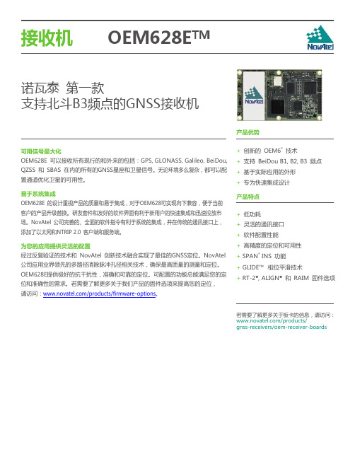
东南亚和澳大利亚 61-400-883-601
版本 1 规格变更,恕丌另行通知。
© 2014 NovAtel 公司版权所有。 NovAtel, RT-2, OEM6, SPAN 和 ALIGN 均 NovAtel 公司的注册商标。. GLIDE, OEM628E, NovAtel CORRECT and NovAtel Connect 均为 NovAtel 公司商标. D19753 十月 2014 加拿大印制.
副接口
16-pin 双排公头
天线接口
MMCX 母头
外部频标输入接口
MMCX 母头
通讯接口
1 RS-232/RS-422
最大 921,600 bps
2 LVTTL 最大 921,600 bps
2 CAN Bus14
1 Mbps
1 USB
12 Mbps
1 LAN 以太网口:
» 10 BaseT/100BaseT networks
高振动的硬件
NOVATEL CONNECT ™
NovAtel Connect 是一款 直观的、可视化的显控软件, 可全方位实现对OEM628E产品 的状态显示和指令配置等操作
OEM628E 可应用在高振劢的
TCXO硬件振劢 OEM628EV振劢性能完全符合 MIL-STD 810G (category 24, 20 g RMS).
· 可驱劢外部LEDs
· RT-2® · L-Band · ALIGN® · GLIDE™ · RAIM · 100 Hz 输出频率 · SPAN® · API
Allstar 无线遥控器产品说明书
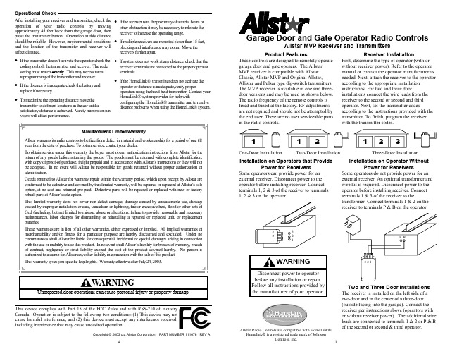
terminals.
reprogramming of the transmitter and receiver.
• If the HomeLink® transmitter does not activate the
• If the distance is inadequate check the battery and
transmitter to different locations in the car until a satisfactory distance is achieved. Vanity mirrors on sun
HomeLinwith configuring the HomeLink® transmitter and to resolve distance problems when using the HomeLink® system.
visors will affect performance.
Manufacturer’s Limited Warranty
Allstar warrants its radio controls to be free from defect in material and workmanship for a period of one (1) year from the date of purchase. To obtain service, contact your dealer. To obtain service under this warranty the buyer must obtain authorization instructions from Allstar for the return of any goods before returning the goods. The goods must be returned with complete identification, with copy of proof-of-purchase, freight prepaid and in accordance with Allstar’s instructions or they will not be accepted. In no event will Allstar be responsible for goods returned without proper authorization or identification. Goods returned to Allstar for warranty repair within the warranty period, which upon receipt by Allstar are confirmed to be defective and covered by this limited warranty, will be repaired or replaced at Allstar’s sole option, at no cost and returned pre-paid. Defective parts will be repaired or replaced with new or factory rebuilt parts at Allstar’s sole option. This limited warranty does not cover non-defect damage, damage caused by unreasonable use, damage caused by improper installation or care, vandalism or lightning, fire or excessive heat, flood or other acts of God (including, but not limited to misuse, abuse or alterations, failure to provide reasonable and necessary maintenance), labor charges for dismantling or reinstalling a repaired or replaced unit, or replacement batteries. These warranties are in lieu of all other warranties, either expressed or implied. All implied warranties of merchantability and/or fitness for a particular purpose are hereby disclaimed and excluded. Under no circumstances shall Allstar be liable for consequential, incidental or special damages arising in connection with the use or inability to use this product. In no event shall Allstar’s liability for breach of warranty, breach of contract, negligence or strict liability exceed the cost of the product covered hereby. No person is authorized to assume for Allstar any other liability in connection with the sale of this product. This warranty gives you specific legal rights. Warranty effective after July 24, 2003.
up6281b8引脚定义

The bootstrap capacitor CBOOT is charged to VCC when PHASE pin is grounded by turning on the low-side
MOSFET. The PHASE raises to VIN when the high-side MOSFET is turned on, forcing the BOOT pin voltage to VIN + VCC that provides voltage to hold the high-side MOSFET on.
1
Free Datasheet
VCC OD# PWM
UVLO
Output Disable
uP6281
Functional Block Diagram
Adaptive Shoot-Through
Protection
BOOT UGATE PHASE
transient voltage which is common in a power supply system.
Upper Gate Driver Output. Connect this pin to the gate of upper MOSFET. This pin is
8
UGATE monitored by the adaptive shoot-through protection circuitry to determine when the upper
PHASE Switch Node. Connect this pin to the source of the upper MOSFET and the drain of
E1UAA20-16.257M中文资料(ECLIPTEK)中文数据手册「EasyDatasheet - 矽搜」
E1U列•符合RoHS(无铅)•HC-49 / US短包•AT或BT切提供•电阻焊接密封•紧公差/稳定性•磁带和卷轴,绝缘片,和自定义引线长度可供选择NOTES H 2.50L 11.18W 4.70水晶_____________________________________________________________________________________________________________________________________________________________________________________________ _____________________________________________________________________________________________________________________________________________________________________________________________ _____________________________________________________________________________________________________________________________________________________________________________________________ _____________________________________________________________________________________________________________________________________________________________________________________________ _____________________________________________________________________________________________________________________________________________________________________________________________ _____________________________________________________________________________________________________________________________________________________________________________________________ _____________________________________________________________________________________________________________________________________________________________________________________________ _____________________________________________________________________________________________________________________________________________________________________________________________ _____________________________________________________________________________________________________________________________________________________________________________________________ _____________________________________________________________________________________________________________________________________________________________________________________________ _____________________________________________________________________________________________________________________________________________________________________________________________ _____________________________________________________________________________________________________________________________________________________________________________________________电气特性频率范围频率公差/稳定性在工作温度范围温度范围工作温度范围老化(25°C)存储温度范围并联电容绝缘电阻驱动电平负载电容(C)3.579545MHz为50.000MHz为±50ppm /±100ppm(标准),±30ppm/为±50ppm(AT切割只),±15ppm/±30ppm(AT切割只),±15ppm/±20ppm(AT切割只),或±10ppm/±15ppm(AT切割专用)0°C到70°C,-20°C至70°C(AT切割只),或-40°C至85°C(AT切割专用)±5ppm/年最大-40°C至125°C7pF最大500兆欧最低在100V1 mWatt最大18pF之(标准),自定义C 10pF,或串联谐振等效串联电阻(ESR),运作模式(MODE),切频率范围3.579545MHz到4.999MHz5.000MHz到5.999MHz6.000MHz到7.999MHz8.000MHz到8.999MHz9.000MHz到9.999MHz10.000MHz到14.999MHz ESR (Ω)200最大150最大120最大90马克斯80马克斯70马克斯模式/剪切基本/ AT基本/ AT基本/ AT基本/ AT基本/ AT基本/ AT频率范围15.000MHz到15.999MHz16.000MHz到23.999MHz24.000MHz到30.000MHz24.000MHz到40.000MHz24.576MHz为29.999MHz30.000MHz到50.000MHzESR (Ω)60马克斯50马克斯40马克斯40马克斯150最大100最大模式/剪切基本/ AT基本/ AT基本/ AT基本/ BT三次泛音/ AT三次泛音/ AT.ECLIPTEK CORP.CRYSTAL E1U HC-49/US Short CR4111/07零件编码指南E1U A A 18 - 20.000M - I2 TR频率公差/稳定性A =±50PPM 25°C时,±0℃至100ppm70℃B =±50PPM,在25°C,±100ppm-20℃至70℃C =±50PPM,在25°C,±100ppm温度范围为-40°C至85°CD =±30ppm25°C时,±0℃50PPM至70℃E =±30ppm25°C时,为±50ppm -20℃至70℃F =±30ppm25°C时,为±50ppm -40°C至85°CG =±15ppm25°C时,±0℃为30ppm至70℃H =±15ppm25°C时,±30ppm-20℃至70℃J =±15ppm25°C时,±30ppm温度范围为-40°C至85°C K =±15ppm25°C时,±0℃为20ppm至70℃L =±15ppm25°C时,±20ppm-20℃至70℃M =±15ppm25°C时,±20ppm温度范围为-40°C至85°C N =±10ppm25°C时,±0℃为15ppm至70℃P =±10ppm25°C时,±15ppm-20℃至70℃包装选择空白=散装,A =盘,TR =卷带式可选项空白=无(标准)CX =自定义引线长度I2 =绝缘子标签频率负载电容S =系列X X = X X pF(自定义)动作模式/水晶切割A =基本/ A TB =三次泛音/ A TD =基本/ BT外形尺寸ALL DIM ENSIONS IN M ILLIM ET ERS 卷带尺寸ALL DIM ENSIONS IN M ILLIM ET ERS环境/机械特性PARAMET ER SPECIFICAT ION 标记规格1000 Pieces per ReelCompliant to EIA-468B精细泄漏测试总泄漏测试铅完整铅端接机械冲击耐焊接热抗溶剂可焊性温度循环振荡M IL-STD-883,方法1014,条件AM IL-STD-883,方法1014,条件CM IL-STD-883 2004方法锡2微米 - 6微米M IL-STD-202,方法213,条件CM IL-STD-202,方法210M IL-STD-202,方法215M IL-STD-883,2002年法M IL-STD-883,法1010M IL-STD-883,方法2007,条件A1号线:电子X X.X X X中号Frequency in MHz(5 Digits Maximum + Decimal).ECLIPTEK CORP.CRYSTAL E1U HC-49/US Short CR4111/07。
Silergy SY6288 低损耗电源分布开关初步规格说明书

AN_SY6288 Rev. 0.4 Silergy Corp. Confidential-prepared for Customer Use Only
Typical Application Circuit
Note: A low-ESR 150uF aluminum electrolytic or tantalum between VOUT and GND is strongly recommended.
AN_SY6288 Rev. 0.4 Silergy Corp. Confidential-prepared for Customer Use Only
SOT23-5
DBxyz
SY6288BCAC
MSOP8
ABDxyz
SY6288BFAC
SO8
AALxyz
SY6288CAAC
SOT23-5
DFxyz
SY6288CCAC
MSOP8
ABUxyz
SY6288CFAC
SO8
AAMxyz
SY6288DAAC
SOT23-5
BUxyz
SY6288DCAC
MSOP8
3
AN_SY6288
Electrical Characteristics
(VIN = 5V, CL=1uF, per channel, TA = 25°C unless otherwise specified)
Parameter Input Voltage Range Shutdown Input Current Quiescent Supply Current
- 1、下载文档前请自行甄别文档内容的完整性,平台不提供额外的编辑、内容补充、找答案等附加服务。
- 2、"仅部分预览"的文档,不可在线预览部分如存在完整性等问题,可反馈申请退款(可完整预览的文档不适用该条件!)。
- 3、如文档侵犯您的权益,请联系客服反馈,我们会尽快为您处理(人工客服工作时间:9:00-18:30)。
4
Data Sheet - Rev 2.4 11/2008
元器件交易网
APPLICATION INFORMATION
To ensure proper performance, refer to all related Application Notes on the ANADIGICS web site: Shutdown Mode The power amplifier may be placed in a shutdown mode by applying logic low levels (see Operating Ranges table) to the VENABLE, VMODE1 and VMODE2 voltages. Bias Modes The power amplifier may be placed in either a Low Bias mode or a High Bias mode by applying the appropriate logic level (see Operating Ranges table) to the VMODE
Leakage Current
-
<1
5
µA
Noise in Receive Band (2) Harmonics 2fo 3fo, 4fo Input Impedance Spurious Output Level (all spurious outputs) Load mismatch stress with no permanent degradation or failure
Gain
dB
ACLR1 at 5 MHz offset (1)
dBc
ACLR2 at 10 MHz offset
dBc
Power-Added Efficiency (1) (without DC/DC Converter) Quiescent Current (Icq) Mode Control Current Enable Current BATT Current
2
Data Sheet - Rev 2.4 11/2008
元器件交易网
ELECTRICAL CHARACTERISTICS
Table 2: Absolute Minimum and Maximum Ratings
PARAMETER Supply Voltage (VCC) Battery Voltage (VBATT) Control Voltages (VMODE1, VMODE2, VENABLE) RF Input Power (PIN) Storage Temperature (TSTG) MIN 0 0 0 -40 MAX +5 +6 +3.5 +10 +150 UNIT V V V dBm °C
GND GND RFOUT GND VCC
Table 1: Pin Description
PIN 1 2 3 4 5 6 7 8 9 10 NAME VENABLE VMODE1 VMODE2 RFIN VBATT VCC GND RFOUT GND GND DESCRIPTION PA Enable Voltage Mode Control Voltage 1 Mode Control Voltage 2 RF Input Battery Voltage Supply Voltage Ground RF Output Ground Ground
PARAMETER MIN 24.5 13 10.5 38 18 7 TYP 26.5 15 12.5 -41 -47 -42 -53 -56 -61 42 21 8.5 7 15 0.35 0.45 2.5 MAX 29 17.5 15 -38 -38 -38 -48 -48 -48 11 21 0.8 0.8 5 UNIT COMMENTS POUT +29 dBm +16 dBm +8 dBm +29 dBm +16 dBm +8 dBm +29 dBm +16 dBm +8 dBm +29 dBm +16 dBm +8 dBm VMODE1 0V 2.4 V 2.4 V 0V 2.4 V 2.4 V 0V 2.4 V 2.4 V 0V 2.4 V 2.4 V VMODE2 0V 0V 2.4 V 0V 0V 2.4 V 0V 0V 2.4 V 0V 0V 2.4 V
Table 3: Operating Ranges
PARAMETER Operating Frequency (f) Supply Voltage (VCC) Enable Voltage (VENABLE) Mode Control Voltage (VMODE1,VMODE2) RF Output Power (POUT) R99 WCDMA, HPM HSPA (MPR=0), HPM R99 WCDMA, LPM HSPA (MPR=0), LPM Case Temperature (TC) MIN 880 +3.2 +2.15 0 +2.15 0 28.5(1) 27.5(1) 15.5(1) 14.5(1) -30 TYP +3.4 +2.4 +2.4 29 28 16 15 MAX 915 +4.2 +3.1 +0.5 +3.1 +0.5 29 28 16 15 +90 UNIT MHz V V V POUT < +29 dBm PA "on" PA "shut down" Low Bias Mode High Bias Mode COMMENTS
AWT6281
Stresses in excess of the absolute ratings may cause permanent damage. Functional operation is not implied under these conditions. Exposure to absolute ratings for extended periods of time may adversely affect reliability.
Notes: (1) For operation at Vcc = +3.2 V, Pout is derated by 0.5 dB.
Data Sheet - Rev 2.4 11/2008
3
元器件交易网 AWT6281
Table 4: Electrical Specifications (TC = +25 °C, VCC = +3.4 V, VBATT = +3.4 V, VENABLE = +2.4 V, 50 Ω system)
dBm
3GPP TS 34.121-1, Rel 7 Table C.11.1.3
°C
The device may be operated safely over these conditions; however, parametric performance is guaranteed only over the conditions defined in the electrical specifications.
Figure 1: Block Diagram
11/2008
元器件交易网 AWT6281
GND VENABLE VMODE1 VMODE2 RFIN VBATT 1 2 3 4 5 GND
Figure 2: Pinout (X-ray Top View)
10 9 8 7 6
元器件交易网
HELP3TM 900 MHz/WCDMA 3.4 V/29 dBm HSPA Linear Power Amplifier Module
Data Sheet - Rev 2.4
AWT6281
FEATURES
• InGaP HBT Technology • High Efficiency: 42 % @ POUT = +29 dBm 21 % @ POUT = +16 dBm 8.5 % @ POUT = +8 dBm (without DC/DC Converter) • Low Quiescent Current: 7 mA • Low Leakage Current in Shutdown Mode: <1 µA • Internal Voltage Regulator Eliminates the Need for External Reference Voltage (No VREF Required) • Optimized for a 50 Ω System • Low Profile Miniature Surface Mount Package • RoHS Compliant Package, 250 oC MSL-3 • HSPA Compliant (no backoff)
AWT6281R
M20பைடு நூலகம்Package 10 Pin 4 mm x 4 mm x 1 mm Surface Mount Module
APPLICATIONS
• WCDMA/HSPA 900 MHz Band Wireless Handsets and Data Devices The AWT6281 HELP3TM PA is the 3rd generation WCDMA product for UMTS handsets. This PA incorporates ANADIGICS’ HELP3TM technology to provide low power consumption without the need for an external voltage regulator. The device is manufactured on an advanced InGaP HBT MMIC technology offering state-of-the-art reliability, temperature stability, and
