v5-4727-4732
常用稳压管型号
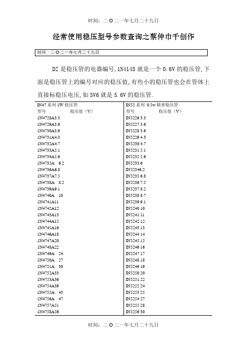
经常使用稳压型号参数查询之蔡仲巾千创作DZ是稳压管的电器编号,1N4148就是一个0.6V的稳压管,下面是稳压管上的编号对应的稳压值,有些小的稳压管也会在管体上直接标稳压电压,如5V6就是5.6V的稳压管.美标稳压二极管型号:HITACHI(日立):HITACHI(日立)0.5W稳压二极管型号参数稳压HZ3A1 2.5~2.7VHZ3A2 2.6~2.8VHZ3A3 2.6~2.9VHZ3B1 2.8~3.0VHZ3B2 2.9~3.1VHZ3B3 3.0~3.2V线性稳压器件(输入输出电流相等,压降3V以上)型号稳压(V) 最年夜输出电流可替代型号79L05 -5V 100mA79L06 -6V 100mA79L08 -8V 100mALM7805 5V 1A L7805,LM340T5LM7806 6V 1A L7806LM7808 8V 1A L7808LM7809 9V 1A L7809LM7812 12V 1A L7812,LM340T12LM7815 15V 1A L7815,LM340T15LM7818 18V 1A L7815LM7824 24V 1A L7824LM7905 -5V 1A L7905LM7906 -6V 1A L7906,KA7906LM7908 -8V 1A L7908LM7909 -9V 1A L7909LM7912 -12V 1A L7912LM7915 -15V 1A L7915LM7918 -18V 1A L7918LM7924 -24V 1A L792478L05 5V 100mA78L06 6V 100mA78L08 8V 100ma78L09 9V 100ma78L12 12V 100ma78L15 15V 100ma78L18 18V 100ma78L24 24V 100ma开关稳压器件(电压转换效率高)型号说明最年夜输出电流LM1575T-3.3 3.3V简易开关电源稳压器1ALM1575T-5.0 5V简易开关电源稳压器1ALM1575T-12 12V简易开关电源稳压器1ALM1575T-15 15V简易开关电源稳压器1ALM1575T-ADJ 简易开关电源稳压器(可调1.23V~37V) 1ALM1575HVT-3.3 3.3V简易开关电源稳压器1ALM1575HVT-5.0 5V简易开关电源稳压器1ALM1575HVT-12 12V简易开关电源稳压器1ALM1575HVT-15 15V简易开关电源稳压器1ALM1575HVT-ADJ 简易开关电源稳压器(可调1.23V~37V) 1ALM2575T-3.3 3.3V简易开关电源稳压器1ALM2575T-5.0 5V简易开关电源稳压器1ALM2575T-12 12V简易开关电源稳压器1ALM2575T-15 15V简易开关电源稳压器1ALM2575T-ADJ 简易开关电源稳压器(可调1.23V~ 37V) 1ALM2575HVT-3.3 3.3V简易开关电源稳压器1ALM2575HVT-5.0 5V简易开关电源稳压器1ALM2575HVT-12 12V简易开关电源稳压器1ALM2575HVT-15 15V简易开关电源稳压器1ALM2575HVT-ADJ 简易开关电源稳压器(可调1.23V~37V) 1ALM2576T-3.3 3.3V简易开关电源稳压器3ALM2576T-5.0 5.0V简易开关电源稳压器3ALM2576T-12 12V简易开关电源稳压器3ALM2576T-15 15V简易开关电源稳压器3ALM2576T-ADJ 简易开关电源稳压器(可调1.23V~37V) 3ALM2576HVT-3.3 3.3V简易开关电源稳压器3ALM2576HVT-5.0 5.0V简易开关电源稳压器3ALM2576HVT-12 12V简易开关电源稳压器3ALM2576HVT-15 15V简易开关电源稳压器3ALM2576HVT-ADJ 简易开关电源稳压器(可调1.23V~37V) 3A。
稳压管对照表
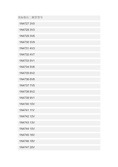
美标稳压二极管型号1N4727 3V01N4728 3V31N4729 3V61N4730 3V91N4731 4V31N4732 4V71N4733 5V11N4734 5V61N4735 6V21N4736 6V81N4737 7V51N4738 8V21N4739 9V11N4740 10V1N4741 11V1N4742 12V1N4743 13V1N4744 15V1N4745 16V1N4746 18V1N4747 20V1N4749 24V1N4750 27V1N4751 30V1N4752 33V1N4753 36V1N4754 39V1N4755 43V1N4756 47V1N4757 51V需要规格书请到以下地址下载,/products/Rectifiers/Diode/Zener/经常看到很多板子上有M记的铁壳封装的稳压管,都是以美标的1N 系列型号标识的,没有具体的电压值,刚才翻手册查了以下3V至51V 的型号与电压的对照值,希望对大家有用1N4727 3V01N4728 3V31N4729 3V61N4730 3V91N4732 4V7 1N4733 5V1 1N4734 5V6 1N4735 6V2 1N4736 6V8 1N4737 7V5 1N4738 8V2 1N4739 9V1 1N4740 10V 1N4741 11V 1N4742 12V 1N4743 13V 1N4744 15V 1N4745 16V 1N4746 18V 1N4747 20V 1N4748 22V 1N4749 24V 1N4750 27V 1N4751 30V 1N4752 33V1N4754 39V1N4755 43V1N4756 47V1N4757 51VDZ是稳压管的电器编号,是和1N4148和相近的,其实1N4148就是一个0.6V的稳压管,下面是稳压管上的编号对应的稳压值,有些小的稳压管也会在管体上直接标稳压电压,如5V6就是5.6V的稳压管。
稳压二极管型号对照表
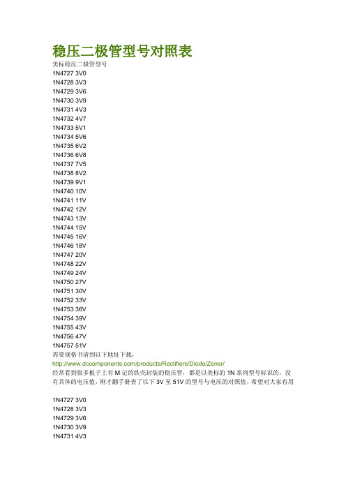
稳压二极管型号对照表美标稳压二极管型号1N4727 3V01N4728 3V31N4729 3V61N4730 3V91N4731 4V31N4732 4V71N4733 5V11N4734 5V61N4735 6V21N4736 6V81N4737 7V51N4738 8V21N4739 9V11N4740 10V1N4741 11V1N4742 12V1N4743 13V1N4744 15V1N4745 16V1N4746 18V1N4747 20V1N4748 22V1N4749 24V1N4750 27V1N4751 30V1N4752 33V1N4753 36V1N4754 39V1N4755 43V1N4756 47V1N4757 51V需要规格书请到以下地址下载,/products/Rectifiers/Diode/Zener/经常看到很多板子上有M记的铁壳封装的稳压管,都是以美标的1N系列型号标识的,没有具体的电压值,刚才翻手册查了以下3V至51V的型号与电压的对照值,希望对大家有用1N4727 3V01N4728 3V31N4729 3V61N4730 3V91N4731 4V31N4733 5V11N4734 5V61N4735 6V21N4736 6V81N4737 7V51N4738 8V21N4739 9V11N4740 10V1N4741 11V1N4742 12V1N4743 13V1N4744 15V1N4745 16V1N4746 18V1N4747 20V1N4748 22V1N4749 24V1N4750 27V1N4751 30V1N4752 33V1N4753 36V1N4754 39V1N4755 43V1N4756 47V1N4757 51VDZ是稳压管的电器编号,是和1N4148和相近的,其实1N4148就是一个0.6V 的稳压管,下面是稳压管上的编号对应的稳压值,有些小的稳压管也会在管体上直接标稳压电压,如5V6就是5.6V的稳压管。
稳压二极管型号大全
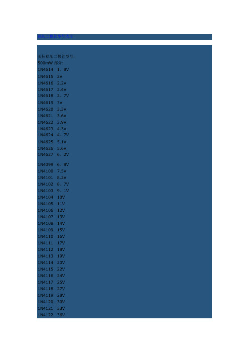
美标稳压二极管型号:500mW部分:1N4614 1。
8V1N4615 2V1N4616 2.2V1N4617 2.4V1N4618 2。
7V1N4619 3V1N4620 3.3V1N4621 3.6V1N4622 3.9V1N4623 4.3V1N4624 4。
7V1N4625 5.1V1N4626 5.6V1N4627 6。
2V1N4099 6。
8V1N4100 7.5V1N4101 8.2V1N4102 8。
7V1N4103 9。
1V1N4104 10V1N4105 11V1N4106 12V1N4107 13V1N4108 14V1N4109 15V1N4110 16V1N4111 17V1N4112 18V1N4113 19V1N4114 20V1N4115 22V1N4116 24V1N4117 25V1N4118 27V1N4119 28V1N4120 30V1N4121 33V1N4122 36V1N4124 43V 1N4125 47V 1N4126 51V 1N4127 56V 1N4128 60V 1N4129 62V 1N4130 68V 1N4131 75V 1N4132 82V 1N4133 87V 1N4134 91V 1N4135 100V1W稳压部分: 1N4727 3V01N4728 3V31N4729 3V61N4730 3V91N4731 4V31N4732 4V71N4733 5V11N4734 5V61N4735 6V21N4736 6V81N4737 7V51N4738 8V21N4739 9V11N4740 10V1N4741 11V1N4742 12V1N4743 13V1N4744 15V1N4745 16V1N4746 18V1N4747 20V1N4748 22V1N4749 24V1N4750 27V1N4751 30V1N4752 33V1N4753 36V1N4754 39V1N4755 43V1N4757 51V1N4758 56V1N4759 62V1N4760 68V1N4761 75V1N4762 82V1N4763 91V1N4764 100VHITACHI(日立)0.5W稳压二极管型号参数HZ3A12.5~2。
常用稳压管型号
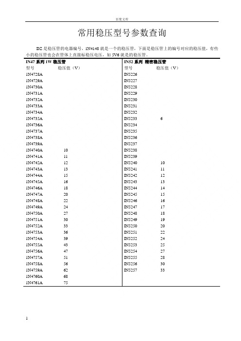
常用稳压型号参数查询DZ是稳压管的电器编号,1N4148就是一个的稳压管,下面是稳压管上的编号对应的稳压值,有些IN47系列1W稳压管型号稳压值(V)1N4728A1N4729A1N4730A1N4731A1N4732A1N4733A1N4734A1N4735A1N4736A1N4737A1N4738A1N4739A1N4740A 101N4741A 111N4742A 121N4743A 131N4744A 151N4745A 161N4746A 181N4747A 201N4748A 221N4749A 241N4750A 271N4751A 301N4752A 331N4753A 361N4754A 391N4755A 431N4756A 471N4757A 511N4758A 561N4759A 621N4760A 681N4761A 75 IN52系列精密稳压管型号稳压值(V)IN5226IN5227IN5228IN5229IN5230IN5231IN5232IN5233 6IN5234IN5235IN5236IN5237IN5238IN5239IN5240 10IN5241 11IN5242 12IN5243 13IN5244 14IN5245 15IN5246 16IN5247 17IN5248 18IN5249 19IN5250 20IN5251 22IN5252 24IN5253 25IN5254 27IN5255 28IN5256 30IN5257 33IN57~IN60系类精密性稳压管型号稳压值(V)IN5730IN5731IN5732IN5733IN5734IN5735IN5736 10IN5737 11IN5738 12IN5739 13IN5740 15IN5741 16IN5742 18IN5743 20IN5744 22IN5745 24IN5746 27IN5747 30IN5748 33IN5749 36IN5750 39IN5985IN5986IN5987 3IN5988IN5989IN5990IN5991IN5992IN5993IN5994IN5995IN5996IN5997IN5998IN5999IN6000 10IN6001 11IN6002 12IN6003 13IN6004 15IN6005 16IN6006 18 贴片型SOD-123穏压二极管型号规格型号稳压值(V)代码标示HZD5221B Z21HZD5222B Z22HZD5223B Z23HZD5224B Z24HZD5225B Z25HZD5226B Z26HZD5227B Z27HZD5228B Z28HZD5229B Z29HZD5230B Z30HZD5231B Z31HZD5232B Z32HZD5233B Z33HZD5234B Z34HZD5235B Z35HZD5236B Z36HZD5237B Z37HZD5238B Z38HZD5239B Z39HZD5240B 10V Z40 HZD5241B 11V Z41 HZD5242B 12V Z42 HZD5243B 13V Z43 HZD5244B 14V Z44IN6007 20 IN6008 22美标稳压二极管型号:500mW部分:型号稳压值(V)1N46141N4615 2V1N46161N46171N46181N4619 3V1N46201N46211N46221N46231N46241N46251N46261N46271N40991N41001N41011N41021N41031N4104 10V1N4105 11V1N4106 12V1N4107 13V1N4108 14V1N4109 15V1N4110 16V1N4111 17V1N4112 18V1N4113 19V1N4114 20V1N4115 22V1N4116 24V1N4117 25V1N4118 27V1N4119 28V1N4120 30V1N4121 33V1N4122 36V1N4123 39V1N4124 43V 1W稳压部分:型号稳压值(V)1N4727 3V01N4728 3V31N4729 3V61N4730 3V91N4731 4V31N4732 4V71N4733 5V11N4734 5V61N4735 6V21N4736 6V81N4737 7V51N4738 8V21N4739 9V11N4740 10V1N4741 11V1N4742 12V1N4743 13V1N4744 15V1N4745 16V1N4746 18V1N4747 20V1N4748 22V1N4749 24V1N4750 27V1N4751 30V1N4752 33V1N4753 36V1N4754 39V1N4755 43V1N4756 47V1N4757 51V1N4758 56V1N4759 62V1N4760 68V1N4761 75V1N4762 82V1N4763 91V1N4764 100V1N4125 47V1N4126 51V1N4127 56V1N4128 60V1N4129 62V1N4130 68V1N4131 75V1N4132 82V1N4133 87V1N4134 91V1N4135 100VHITACHI(日立):HITACHI(日立)稳压二极管型号参数稳压HZ3A1 ~HZ3A2 ~HZ3A3 ~HZ3B1 ~HZ3B2 ~HZ3B3 ~线性稳压器件(输入输出电流相等,压降3V以上)型号稳压(V) 最大输出电流可替代型号79L05 -5V 100mA79L06 -6V 100mA79L08 -8V 100mALM7805 5V 1A L7805,LM340T5 LM7806 6V 1A L7806LM7808 8V 1A L7808LM7809 9V 1A L7809LM7812 12V 1A L7812,LM340T12 LM7815 15V 1A L7815,LM340T15 LM7818 18V 1A L7815LM7824 24V 1A L7824LM7905 -5V 1A L7905LM7906 -6V 1A L7906,KA7906 LM7908 -8V 1A L7908LM7909 -9V 1A L7909LM7912 -12V 1A L7912LM7915 -15V 1A L7915LM7918 -18V 1A L7918LM7924 -24V 1A L792478L05 5V 100mA78L06 6V 100mA78L08 8V 100ma78L09 9V 100ma78L12 12V 100ma78L15 15V 100ma78L18 18V 100ma78L24 24V 100ma开关稳压器件(电压转换效率高)型号说明最大输出电流简易开关电源稳压器1A5V简易开关电源稳压器1ALM1575T-12 12V简易开关电源稳压器1ALM1575T-15 15V简易开关电源稳压器1ALM1575T-ADJ 简易开关电源稳压器(可调~37V) 1A 简易开关电源稳压器1A5V简易开关电源稳压器1ALM1575HVT-12 12V简易开关电源稳压器1ALM1575HVT-15 15V简易开关电源稳压器1ALM1575HVT-ADJ 简易开关电源稳压器(可调~37V) 1A简易开关电源稳压器1A5V简易开关电源稳压器1ALM2575T-12 12V简易开关电源稳压器1ALM2575T-15 15V简易开关电源稳压器1ALM2575T-ADJ 简易开关电源稳压器(可调~ 37V) 1A 简易开关电源稳压器1A5V简易开关电源稳压器1ALM2575HVT-12 12V简易开关电源稳压器1ALM2575HVT-15 15V简易开关电源稳压器1ALM2575HVT-ADJ 简易开关电源稳压器(可调~37V) 1A 简易开关电源稳压器3A简易开关电源稳压器3ALM2576T-12 12V简易开关电源稳压器3ALM2576T-15 15V简易开关电源稳压器3ALM2576T-ADJ 简易开关电源稳压器(可调~37V) 3A 简易开关电源稳压器3A简易开关电源稳压器3ALM2576HVT-12 12V简易开关电源稳压器3ALM2576HVT-15 15V简易开关电源稳压器3ALM2576HVT-ADJ 简易开关电源稳压器(可调~37V) 3A。
常用稳压二极管型号
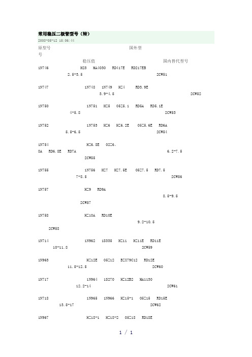
常用稳压二极管型号(转)2008-05-12 15:06:44原型号国外型号稳压值国内替代型号1N746 H23 MA4030 RD417E RD217EB2.5-3.5 2CW511N747 1N748 1N749 HZ4 RD3.9E3.9-4.5 2CW521N750 1N751 HZ5 05Z5.1 RD5A RD5.1E4-5.8 2CW531N752 1N753 HZ6 HZ6.2E 05Z5.6E RD6A5.5-6.5 2CW541N754 HZ6.8E 02Z6。
8A RD6.8E RD7A 6.2-7.52CW551N755 1N756 HZ7 HZ7.5E 05Z7.5 RD7.57-8.5 2CW561N757 HZ9 RD9A8.5-9.52CW571N758 HZ10A RD10E9.2-10.52CW581N714 1N962 1S335 HZ11 HZ11E RD11E10-11.8 2CW591N963 HZ12E 05Z12 BZX79C12 RD12E11.5-12.5 2CW601N717 1N964 1S270 HZ12B2 MA113012.2-14 2CW611N718 1N965 1N966 HZ15-1 05Z15 RD15E13.5-17 2CW621N967 HZ18-1 HZ18-2 05Z18 RD18E16-19 2CW631N968 HZ20-1 RD20E18-212CW641N969 HZ24E RD24E20-242CW651N970 02Z2423-262CW661N971 HZ2725-282CW671N972 RD31E27-322CW681N973 1N974 HZ733 ZX0249E UPC574J31-35 2CW69 2CW70稳压二极管型号对照表美标稳压二极管型号1N4727 3V01N4728 3V31N4729 3V61N4730 3V91N4731 4V31N4732 4V71N4733 5V11N4734 5V61N4735 6V21N4736 6V81N4737 7V51N4738 8V21N4739 9V11N4740 10V1N4741 11V1N4742 12V1N4743 13V1N4744 15V1N4745 16V1N4746 18V1N4747 20V1N4748 22V1N4749 24V1N4750 27V1N4751 30V1N4752 33V1N4753 36V1N4754 39V1N4755 43V1N4756 47V1N4757 51V需要规格书请到以下地址下载,/products/Rectifiers/Diode/Zener/经常看到很多板子上有M记的铁壳封装的稳压管,都是以美标的1N系列型号标识的,没有具体的电压值,刚才翻手册查了以下3V至51V的型号与电压的对照值,希望对大家有用1N4727 3V01N4728 3V31N4729 3V61N4730 3V91N4731 4V31N4732 4V71N4733 5V11N4734 5V61N4735 6V21N4736 6V81N4737 7V51N4738 8V21N4739 9V11N4740 10V1N4741 11V1N4742 12V1N4743 13V1N4744 15V1N4745 16V1N4746 18V1N4747 20V1N4748 22V1N4749 24V1N4750 27V1N4751 30V1N4752 33V1N4753 36V1N4754 39V1N4755 43V1N4756 47V1N4757 51VDZ是稳压管的电器编号,是和1N4148和相近的,其实1N4148就是一个0.6V的稳压管,下面是稳压管上的编号对应的稳压值,有些小的稳压管也会在管体上直接标稳压电压,如5V6就是5.6V的稳压管。
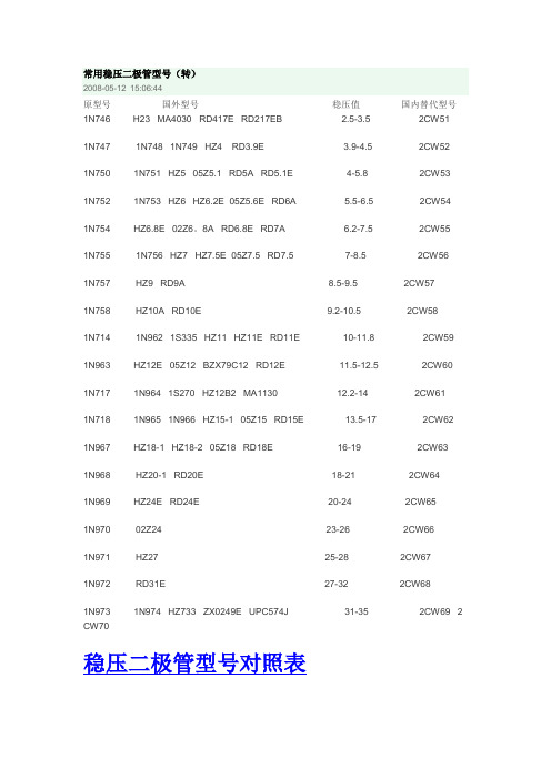
常用稳压二极管型号

常用稳压二极管型号(转)2008-05-12 15:06:44原型号国外型号稳压值国内替代型号1N746 H23 MA4030 RD417E RD217EB 2.5-3.5 2CW511N747 1N748 1N749 HZ4 RD3.9E 3.9-4.5 2CW521N750 1N751 HZ5 05Z5.1 RD5A RD5.1E 4-5.8 2CW531N752 1N753 HZ6 HZ6.2E 05Z5.6E RD6A 5.5-6.5 2CW541N754 HZ6.8E 02Z6。
8A RD6.8E RD7A 6.2-7.5 2CW551N755 1N756 HZ7 HZ7.5E 05Z7.5 RD7.5 7-8.5 2CW561N757 HZ9 RD9A 8.5-9.5 2CW571N758 HZ10A RD10E 9.2-10.5 2CW581N714 1N962 1S335 HZ11 HZ11E RD11E 10-11.8 2CW591N963 HZ12E 05Z12 BZX79C12 RD12E 11.5-12.5 2CW601N717 1N964 1S270 HZ12B2 MA1130 12.2-14 2CW611N718 1N965 1N966 HZ15-1 05Z15 RD15E 13.5-17 2CW621N967 HZ18-1 HZ18-2 05Z18 RD18E 16-19 2CW631N968 HZ20-1 RD20E 18-21 2CW641N969 HZ24E RD24E 20-24 2CW651N970 02Z24 23-26 2CW661N971 HZ27 25-28 2CW671N972 RD31E 27-32 2CW681N973 1N974 HZ733 ZX0249E UPC574J 31-35 2CW69 2 CW70稳压二极管型号对照表美标稳压二极管型号1N4727 3V01N4728 3V31N4729 3V61N4730 3V91N4731 4V31N4732 4V71N4733 5V11N4734 5V61N4735 6V21N4736 6V81N4737 7V51N4738 8V21N4739 9V11N4740 10V1N4741 11V1N4742 12V1N4743 13V1N4744 15V1N4745 16V1N4746 18V1N4747 20V1N4748 22V1N4749 24V1N4750 27V1N4751 30V1N4752 33V1N4753 36V1N4754 39V1N4755 43V1N4756 47V1N4757 51V需要规格书请到以下地址下载,/products/Rectifiers/Diode/Zener/经常看到很多板子上有M记的铁壳封装的稳压管,都是以美标的1N系列型号标识的,没有具体的电压值,刚才翻手册查了以下3V至51V的型号与电压的对照值,希望对大家有用1N4727 3V01N4728 3V31N4729 3V61N4730 3V91N4731 4V31N4732 4V71N4733 5V11N4735 6V21N4736 6V81N4737 7V51N4738 8V21N4739 9V11N4740 10V1N4741 11V1N4742 12V1N4743 13V1N4744 15V1N4745 16V1N4746 18V1N4747 20V1N4748 22V1N4749 24V1N4750 27V1N4751 30V1N4752 33V1N4753 36V1N4754 39V1N4755 43V1N4756 47V1N4757 51VDZ是稳压管的电器编号,是和1N4148和相近的,其实1N4148就是一个0.6V的稳压管,下面是稳压管上的编号对应的稳压值,有些小的稳压管也会在管体上直接标稳压电压,如5V6就是5.6V的稳压管。
常用稳压二极管型号
常用稳压二极管型号(转)2008-05-12 15:06:44原型号国外型号稳压值国内替代型号1N746 H23 MA4030 RD417E RD217EB 2.5-3.5 2CW511N747 1N748 1N749 HZ4 RD3.9E 3.9-4.5 2CW521N750 1N751 HZ5 05Z5.1 RD5A RD5.1E 4-5.8 2CW531N752 1N753 HZ6 HZ6.2E 05Z5.6E RD6A 5.5-6.5 2CW541N754 HZ6.8E 02Z6。
8A RD6.8E RD7A 6.2-7.5 2CW551N755 1N756 HZ7 HZ7.5E 05Z7.5 RD7.5 7-8.5 2CW561N757 HZ9 RD9A 8.5-9.5 2CW571N758 HZ10A RD10E 9.2-10.5 2CW581N714 1N962 1S335 HZ11 HZ11E RD11E 10-11.8 2CW591N963 HZ12E 05Z12 BZX79C12 RD12E 11.5-12.5 2CW601N717 1N964 1S270 HZ12B2 MA1130 12.2-14 2CW611N718 1N965 1N966 HZ15-1 05Z15 RD15E 13.5-17 2CW621N967 HZ18-1 HZ18-2 05Z18 RD18E 16-19 2CW631N968 HZ20-1 RD20E 18-21 2CW641N969 HZ24E RD24E 20-24 2CW651N970 02Z24 23-26 2CW661N971 HZ27 25-28 2CW671N972 RD31E 27-32 2CW681N973 1N974 HZ733 ZX0249E UPC574J 31-35 2CW69 2 CW70稳压二极管型号对照表美标稳压二极管型号1N4727 3V01N4728 3V31N4729 3V61N4730 3V91N4731 4V31N4732 4V71N4733 5V11N4734 5V61N4735 6V21N4736 6V81N4737 7V51N4738 8V21N4739 9V11N4740 10V1N4741 11V1N4742 12V1N4743 13V1N4744 15V1N4745 16V1N4746 18V1N4747 20V1N4748 22V1N4749 24V1N4750 27V1N4751 30V1N4752 33V1N4753 36V1N4754 39V1N4755 43V1N4756 47V1N4757 51V需要规格书请到以下地址下载,经常看到很多板子上有M记的铁壳封装的稳压管,都是以美标的1N系列型号标识的,没有具体的电压值,刚才翻手册查了以下3V至51V的型号与电压的对照值,希望对大家有用1N4727 3V01N4728 3V31N4729 3V61N4730 3V91N4731 4V31N4732 4V71N4733 5V11N4735 6V21N4736 6V81N4737 7V51N4738 8V21N4739 9V11N4740 10V1N4741 11V1N4742 12V1N4743 13V1N4744 15V1N4745 16V1N4746 18V1N4747 20V1N4748 22V1N4749 24V1N4750 27V1N4751 30V1N4752 33V1N4753 36V1N4754 39V1N4755 43V1N4756 47V1N4757 51VDZ是稳压管的电器编号,是和1N4148和相近的,其实1N4148就是一个0.6V的稳压管,下面是稳压管上的编号对应的稳压值,有些小的稳压管也会在管体上直接标稳压电压,如5V6就是5.6V的稳压管。
稳压二极管的工作原理及型号
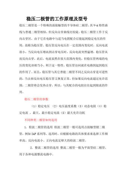
稳压二极管的工作原理及型号稳压二极管是一个特殊的面接触型的半导体硅二极管,其V-A特性曲线与普通二极管相似,但反向击穿曲线比较陡。
稳压二极管工作于反向击穿区,由于它在电路中与适当电阴配合后能起到稳定电压的作用,故称为稳压管。
稳压管反向电压在一定范围内变化时,反向电流很小,当反向电压增高到击穿电压时,反向电流突然猛增,稳压管从而反向击穿,此后,电流虽然在很大范围内变化,但稳压管两端的电压的变化却相当小,利于这一特性,稳压管访问就在电路到起到稳压的作用了。
而且,稳压管与其它普能二极管不同之反向击穿是可逆性的,当去掉反向电压稳压管又恢复正常,但如果反向电流超过允许范围,二极管将会发热击穿,所以,与其配合的电阻往往起到限流的作用。
稳压二极管的参数:(1)稳定电压(2)电压温度系数(3)动态电阻(4)稳定电流,最大、最小稳定电流(5)最大允许功耗不同种类二极管如何选用1.检波二极管的选用检波二极管一般可选用点接触型锗二极管,例如2AP系列等。
选用时,应根据电路的具体要求来选择工作频率高、反向电流小、正向电流足够大的检波二极管。
2.整流二极管的选用整流二极管一般为平面型硅二极管,用于各种电源整流电路中。
选用整流二极管时,主要应考虑其最大整流电流、最大反向工作电流、截止频率及反向恢复时间等参数。
普通串联稳压电源电路中使用的整流二极管,对截止频率的反向恢复时间要求不高,只要根据电路的要求选择最大整流电流和最大反向工作电流符合要求的整流二极管即可。
例如,1N系列、2CZ系列、RLR系列等。
开关稳压电源的整流电路及脉冲整流电路中使用的整流二极管,应选用工作频率较高、反向恢复时间较短的整流二极管(例如RU系列、EU系列、V系列、1SR系列等)或选择快恢复二极管。
3.稳压二极管的选用稳压二极管一般用在稳压电源中作为基准电压源或用在过电压保护电路中作为保护二极管。
选用的稳压二极管,应满足应用电路中主要参数的要求。
稳压二极管的稳定电压值应与应用电路的基准电压值相同,稳压二极管的最大稳定电流应高于应用电路的最大负载电流50%左右。
常用稳压二极管型号
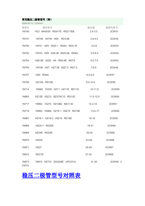
常用稳压二极管型号(转)2008-05-12 15:06:44原型号国外型号稳压值国替代型号1N746 H23 MA4030 RD417E RD217EB 2.5-3.5 2CW511N747 1N748 1N749 HZ4 RD3.9E 3.9-4.5 2CW521N750 1N751 HZ5 05Z5.1 RD5A RD5.1E 4-5.8 2CW53 1N752 1N753 HZ6 HZ6.2E 05Z5.6E RD6A 5.5-6.5 2CW541N754 HZ6.8E 02Z6。
8A RD6.8E RD7A 6.2-7.5 2CW551N755 1N756 HZ7 HZ7.5E 05Z7.5 RD7.5 7-8.5 2CW561N757 HZ9 RD9A 8.5-9.5 2CW571N758 HZ10A RD10E 9.2-10.5 2CW581N714 1N962 1S335 HZ11 HZ11E RD11E 10-11.8 2CW59 1N963 HZ12E 05Z12 BZX79C12 RD12E 11.5-12.5 2CW601N717 1N964 1S270 HZ12B2 MA1130 12.2-14 2CW611N718 1N965 1N966 HZ15-1 05Z15 RD15E 13.5-17 2CW62 1N967 HZ18-1 HZ18-2 05Z18 RD18E 16-19 2CW631N968 HZ20-1 RD20E 18-21 2CW641N969 HZ24E RD24E 20-24 2CW651N970 02Z24 23-26 2CW661N971 HZ27 25-28 2CW671N972 RD31E 27-32 2CW681N973 1N974 HZ733 ZX0249E UPC574J 31-35 2CW69 2 CW70稳压二极管型号对照表美标稳压二极管型号1N4727 3V01N4728 3V31N4729 3V61N4730 3V91N4731 4V31N4732 4V71N4733 5V11N4734 5V61N4735 6V21N4736 6V81N4737 7V51N4738 8V21N4739 9V11N4740 10V1N4741 11V1N4742 12V1N4743 13V1N4744 15V1N4745 16V1N4746 18V1N4747 20V1N4748 22V1N4749 24V1N4750 27V1N4751 30V1N4752 33V1N4753 36V1N4754 39V1N4755 43V1N4756 47V1N4757 51V需要规格书请到以下地址下载,.dccomponents./products/Rectifiers/Diode/Zener/经常看到很多板子上有M记的铁壳封装的稳压管,都是以美标的1N系列型号标识的,没有具体的电压值,刚才翻手册查了以下3V至51V的型号与电压的对照值,希望对大家有用1N4727 3V01N4728 3V31N4729 3V61N4730 3V91N4731 4V31N4732 4V71N4733 5V11N4735 6V21N4736 6V81N4737 7V51N4738 8V21N4739 9V11N4740 10V1N4741 11V1N4742 12V1N4743 13V1N4744 15V1N4745 16V1N4746 18V1N4747 20V1N4748 22V1N4749 24V1N4750 27V1N4751 30V1N4752 33V1N4753 36V1N4754 39V1N4755 43V1N4756 47V1N4757 51VDZ是稳压管的电器编号,是和1N4148和相近的,其实1N4148就是一个0.6V的稳压管,下面是稳压管上的编号对应的稳压值,有些小的稳压管也会在管体上直接标稳压电压,如5V6就是5.6V的稳压管。
常用稳压二极管型号

1N750 1N751HZ5 05Z5.1 RD5A RD5.1E4-5.8 2CW53
1N752 1N753HZ6HZ6.2E05Z5.6E RD6A 5.5-6.52CW54
1N754 HZ6.8E02Z6。8ARD6.8E RD7A 6.2-7.5 2CW55
ﻫ1N47273V0
1N47283V3
1N47293V6
1N47303V9
1N47314V3
1N4732 4V7
1N47335V1
1N47345V6
1N4735 6V2
1N47366V8
1N47377V5ﻫ1N4738 8V2ﻫ1N47399V1
1N474010V
1N474111Vﻫ1N4742 12V
1N7551N756HZ7HZ7.5E05Z7.5 RD7.57-8.5 2CW56
1N757HZ9 RD9A 8.5-9.5 2CW57
1N758HZ10A RD10E9.2-10.5 2CW58
1N7141N962 1S335HZ11 HZ11ERD11E 10-11.8 2CW59
1N963HZ12E 05Z12BZX79C12 RD12E 11.5-12.52CW60
DZ是稳压管的电器编号,是和1N4148和相近的,其实1N4148就是一个0.6V的稳压管,下面是稳压管上的编号对应的稳压值,有些小的稳压管也会在管体上直接标稳压电压,如5V6就是5.6V的稳压管。ﻫ1N4728A3.3
1N4729A3.6ﻫ1N4730A 3.9
1N4731A 4.3ﻫ1N4732A4.7
常用稳压二极管型号
————————————————————————————————作者:
常用稳压管型号

常用稳压管型号Company Document number:WTUT-WT88Y-W8BBGB-BWYTT-19998常用稳压型号参数查询DZ是稳压管的电器编号,1N4148就是一个的稳压管,下面是稳压管上的编号对应的稳压值,有些小的稳压管也会在管体上直接标稳压电压,如5V6就是的稳压管。
美标稳压二极管型号:HITACHI(日立):HITACHI(日立)稳压二极管型号参数稳压HZ3A1 ~HZ3A3 ~HZ3B1 ~HZ3B2 ~HZ3B3 ~线性稳压器件(输入输出电流相等,压降3V以上) 型号稳压(V) 最大输出电流可替代型号79L05 -5V 100mA79L06 -6V 100mA79L08 -8V 100mALM7805 5V 1A L7805,LM340T5LM7806 6V 1A L7806LM7808 8V 1A L7808LM7809 9V 1A L7809LM7812 12V 1A L7812,LM340T12LM7815 15V 1A L7815,LM340T15LM7818 18V 1A L7815LM7824 24V 1A L7824LM7905 -5V 1A L7905LM7906 -6V 1A L7906,KA7906LM7908 -8V 1A L7908LM7909 -9V 1A L7909LM7912 -12V 1A L7912LM7915 -15V 1A L7915LM7918 -18V 1A L7918LM7924 -24V 1A L792478L05 5V 100mA78L06 6V 100mA78L08 8V 100ma78L09 9V 100ma78L12 12V 100ma78L15 15V 100ma78L18 18V 100ma78L24 24V 100ma开关稳压器件(电压转换效率高)型号说明最大输出电流简易开关电源稳压器 1A5V简易开关电源稳压器 1ALM1575T-12 12V简易开关电源稳压器 1ALM1575T-15 15V简易开关电源稳压器 1ALM1575T-ADJ 简易开关电源稳压器(可调~37V) 1A简易开关电源稳压器 1A5V简易开关电源稳压器 1ALM1575HVT-12 12V简易开关电源稳压器 1ALM1575HVT-15 15V简易开关电源稳压器 1ALM1575HVT-ADJ 简易开关电源稳压器(可调~37V) 1A 简易开关电源稳压器 1A5V简易开关电源稳压器 1ALM2575T-12 12V简易开关电源稳压器 1ALM2575T-15 15V简易开关电源稳压器 1ALM2575T-ADJ 简易开关电源稳压器(可调~ 37V) 1A简易开关电源稳压器 1A5V简易开关电源稳压器 1ALM2575HVT-15 15V简易开关电源稳压器 1A LM2575HVT-ADJ 简易开关电源稳压器(可调~37V) 1A 简易开关电源稳压器 3A简易开关电源稳压器 3ALM2576T-12 12V简易开关电源稳压器 3A LM2576T-15 15V简易开关电源稳压器 3A LM2576T-ADJ 简易开关电源稳压器(可调~37V) 3A简易开关电源稳压器 3A简易开关电源稳压器 3ALM2576HVT-12 12V简易开关电源稳压器 3A LM2576HVT-15 15V简易开关电源稳压器 3A LM2576HVT-ADJ 简易开关电源稳压器(可调~37V) 3A。
稳压管型 参数对照表
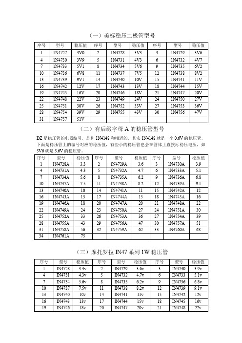
(一)美标稳压二极管型号序号型号稳压值序号型号稳压值序号型号稳压值1 1N4727 3V0 2 1N4728 3V3 3 1N4729 3V6 4 1N4730 3V9 5 1N4731 4V3 6 1N4732 4V7 7 1N4733 5V1 8 1N4734 5V6 9 1N4735 6V2 10 1N4736 6V8 11 1N4737 7V5 12 1N4738 8V2 13 1N4739 9V1 14 1N4740 10V 15 1N4741 11V 16 1N4742 12V 17 1N4743 13V 18 1N4744 15V 19 1N4745 16V 20 1N4746 18V 21 1N4747 20V 22 1N4748 22V 23 1N4749 24V 24 1N4750 27V 25 1N4751 30V 26 1N4752 33V 27 1N4753 36V 28 1N4754 39V 29 1N4755 43V 30 1N4756 47V 31 1N4757 51V(二)有后缀字母A的稳压管型号DZ是稳压管的电器编号,是和1N4148和相近的,其实1N4148就是一个0.6V的稳压管,下面是稳压管上的编号对应的稳压值,有些小的稳压管也会在管体上直接标稳压电压,如5V6就是5.6V的稳压管。
序号型号稳压值序号型号稳压值序号型号稳压值1 1N4728A 3.3 2 1N4729A 3.6 3 1N4730A 3.9 4 1N4731A 4.3 5 1N4732A 4.7 6 1N4733A 5.1 7 1N4734A 5.6 8 1N4735A 6.2 9 1N4736A 6.8 10 1N4737A 7.5 11 1N4738A 8.2 12 1N4739A 9.1 13 1N4740A 10 14 1N4741A 11 15 1N4742A 12 16 1N4743A 13 17 1N4744A 15 18 1N4745A 16 19 1N4746A 18 20 1N4747A 20 21 1N4748A 22 22 1N4749A 24 23 1N4750A 27 24 1N4751A 30 25 1N4752A 33 26 1N4753A 36 27 1N4754A 39 28 1N4755A 43 29 1N4756A 47 30 1N4757A 51 31 1N4758A 56 32 1N4759A 62 33 1N4760A 68 34 1N4761A 75(三)摩托罗拉IN47系列1W稳压管序号型号稳压值序号型号稳压值序号型号稳压值1 IN4728 3.3v2 IN4729 3.6v3 IN4730 3.9v4 IN4731 4.3v5 IN4732 4.7v6 IN4733 5.1v7 IN4734 5.6v 8 IN4735 6.2v 9 IN4736 6.8v10 IN4737 7.5v 11 IN4738 8.2v 12 IN4739 9.1v13 IN4740 10v 14 IN4741 11v 15 IN4742 12v16 IN4743 13v 17 IN4744 15v 18 IN4745 16v19 IN4746 18v 20 IN4747 20v 21 IN4748 22v序号型号稳压值序号型号稳压值序号型号稳压值22 IN4749 24v 23 IN4750 27v 24 IN4751 30v 25 IN4752 33v 26 IN4753 34v 27 IN4754 35v 28 IN4755 36v 29 IN4756 47v 30 IN4757 51v(四)摩托罗拉IN52系列0.5w精密稳压管序号型号稳压值序号型号稳压值序号型号稳压值1 IN5226 3.3v 2 IN5227 3.6v 3 IN5228 3.9v 4 IN5229 4.3v 5 IN5230 4.7v 6 IN5231 5.1v 7 IN5232 5.6v 8 IN5233 6.0v 9 IN5234 6.2v 10 IN5235 6.8v 11 IN5236 7.5v 12 IN5237 8.2v 13 IN5238 8.7v 14 IN5239 9.1v 15 IN5240 10v 16 IN5241 11v 17 IN5242 12v 18 IN5243 13v 19 IN5244 14v 20 IN5245 15v 21 IN5246 16v 22 IN5247 17v 23 IN5248 18v 24 IN5249 19v 25 IN5250 20v 26 IN5251 22v 27 IN5252 24v 28 IN5253 25v 29 IN5254 27v 30 IN5255 28v 31 IN5256 30v 32 IN5257 33vIN57系列序号型号稳压值序号型号稳压值序号型号稳压值1 IN5730 5.6v 2 IN5731 6.2v 3 IN5732 6.8v 4 IN5733 7.5v 5 IN5734 8.2v 6 IN5735 9.1v 7 IN5736 10v 8 IN5737 11v 9 IN5738 12v 10 IN5739 13v 11 IN5740 15v 12 IN5741 16v 13 IN5742 18v 14 IN5743 20v 15 IN5744 22v 16 IN5745 24v 17 IN5746 27v 18 IN5747 30v 19 IN5748 33v 20 IN5749 36v 21 IN5750 39vIN59系列序号型号稳压值序号型号稳压值序号型号稳压值1 IN5985 2.4v 2 IN5986 2.7v 3 IN5987 3v 4 IN5988 3.3v 5 IN5989 3.6v 6 IN5990 3.9v 7 IN5991 4.3v 8 IN5992 4.7v 9 IN5993 5.1v 10 IN5994 5.6v 11 IN5995 6.2v 12 IN5996 6.8v 13 IN5997 7.5v 14 IN5998 8.2v 15 IN5999 9.1v 16 IN6000 10v 17 IN6001 11v 18 IN6002 12v 19 IN6003 13v 20 IN6004 15v 21 IN6005 16v 22 IN6006 18v 23 IN6007 20v 24 IN6008 22v(五)贴片型SOD-123穏压二极管Marking Code SINLOONSMD SOD-123 Zener DiodeType /V oltage / Marking Code序号型号代码标示电压序号型号代码标示电压HZD5221B Z21 2.4V HZD5222B Z22 2.5V HZD5223B Z23 2.7V HZD5224B Z24 2.8V HZD5225B Z25 3.0V HZD5226B Z26 3.3V HZD5227B Z27 3.6V HZD5228B Z28 3.9V HZD5229B Z29 4.3V HZD5230B Z30 4.7V HZD5231B Z31 5.1V HZD5232B Z32 5.6V HZD5233B Z33 6.0V HZD5234B Z34 6.2V HZD5235B Z35 6.8V HZD5236B Z36 7.5V HZD5237B Z37 8.2V HZD5238B Z38 8.7V HZD5239B Z39 9.1V HZD5240B Z40 10V HZD5241B Z41 11V HZD5242B Z42 12V HZD5243B Z43 13V HZD5244B Z44 14V HZD5245B Z45 15V。
稳压二极管型号大全

稳压两极管型号大齐之阳早格格创做1N4099 6.8V 1N4100 7.5V 1N4101 8.2V 1N4102 8.7V 1N4103 9.1V 1N4104 10V 1N4105 11V 1N4106 12V 1N4107 13V 1N4108 14V 1N4109 15V 1N4110 16V 1N4111 17V 1N4112 18V 1N4113 19V 1N4114 20V 1N4115 22V 1N4116 24V 1N4117 25V 1N4118 27V 1N4119 28V 1N4120 30V 1N4121 33V 1N4122 36V 1N4123 39V 1N4124 43V 1N4125 47V 1N4126 51V 1N4127 56V 1N4128 60V 1N4129 62V 1N4130 68V 1N4131 75V 1N4132 82V 1N4133 87V 1N4134 91V 1N4135 100V1W稳压部分: 1N4727 3V0 1N4728 3V3 1N4729 3V6 1N4730 3V9 1N4731 4V3 1N4732 4V7 1N4733 5V1 1N4734 5V6 1N4735 6V2 1N4736 6V8 1N4737 7V5 1N4738 8V2 1N4739 9V1 1N4740 10V 1N4741 11V 1N4742 12V 1N4743 13V 1N4744 15V 1N4745 16V 1N4746 18V 1N4747 20V 1N4748 22V 1N4749 24V 1N4750 27V 1N4751 30V 1N4752 33V 1N4753 36V 1N4754 39V 1N4755 43V 1N4756 47V 1N4757 51V 1N4758 56V 1N4759 62V 1N4760 68V 1N4761 75V 1N4762 82V 1N4763 91V 1N4764 100VHITACHI(日坐)0.5W稳压两极管型号参数线性稳压器件(输进输出电流相等,压落3V以上) 型号稳压(V) 最大输出电流可代替型号79L05 -5V 100mA79L06 -6V 100mA 79L08 -8V 100mA LM7805 5V1A L7805,LM340T5 LM7806 6V 1A L7806LM7808 8V 1A L7808 LM7809 9V 1A L7809 LM7812 12V 1A L7812,LM340T12LM7815 15V 1A L7815,LM340T15 LM7818 18V1A L7815 LM7824 24V 1A L7824 LM7905-5V 1A L7905 LM7906 -6V 1A L7906,KA7906 LM7908 -8V 1A L7908 LM7909-9V 1A L7909 LM7912 -12V 1A L7912LM7915 -15V 1A L7915 LM7918 -18V 1A L7918 LM7924 -24V 1A L7924 78L05 5V 100mA 78L06 6V 100mA 78L08 8V 100ma78L09 9V 100ma 78L12 12V 100ma 78L15 15V 100ma 78L18 18V 100ma 78L24 24V 100ma启闭稳压器件(电压变换效用下) 型号证明最大输出电流LM1575T-3.3 3.3V浅易启闭电源稳压器1A LM1575T-5.0 5V浅易启闭电源稳压器 1A LM1575T-12 12V浅易启闭电源稳压器1A LM1575T-15 15V浅易启闭电源稳压器1A LM1575T-ADJ 浅易启闭电源稳压器(可调1.23V~37V) 1ALM1575HVT-3.3 3.3V浅易启闭电源稳压器1A LM1575HVT-5.0 5V浅易启闭电源稳压器1A LM1575HVT-12 12V浅易启闭电源稳压器1A LM1575HVT-15 15V浅易启闭电源稳压器1A LM1575HVT-ADJ 浅易启闭电源稳压器(可调1.23V~37V) 1A LM2575T-3.3 3.3V浅易启闭电源稳压器 1A LM2575T-5.0 5V浅易启闭电源稳压器1A LM2575T-12 12V浅易启闭电源稳压器1A LM2575T-15 15V浅易启闭电源稳压器1A LM2575T-ADJ 浅易启闭电源稳压器(可调1.23V~ 37V) 1A LM2575HVT-3.3 3.3V浅易启闭电源稳压器1A LM2575HVT-5.0 5V浅易启闭电源稳压器1A LM2575HVT-12 12V浅易启闭电源稳压器1A LM2575HVT-15 15V浅易启闭电源稳压器1A LM2575HVT-ADJ 浅易启闭电源稳压器(可调1.23V~37V) 1A LM2576T-3.3 3.3V浅易启闭电源稳压器 3A LM2576T-5.0 5.0V浅易启闭电源稳压器3A LM2576T-12 12V浅易启闭电源稳压器3A LM2576T-15 15V浅易启闭电源稳压器3A LM2576T-ADJ 浅易启闭电源稳压器(可调1.23V~37V) 3A LM2576HVT-3.3 3.3V浅易启闭电源稳压器3A LM2576HVT-5.0 5.0V浅易启闭电源稳压器3ALM2576HVT-12 12V浅易启闭电源稳压器3A LM2576HVT-15 15V浅易启闭电源稳压器3A LM2576HVT-ADJ 浅易启闭电源稳压器(可调1.23V~37V) 3A。
- 1、下载文档前请自行甄别文档内容的完整性,平台不提供额外的编辑、内容补充、找答案等附加服务。
- 2、"仅部分预览"的文档,不可在线预览部分如存在完整性等问题,可反馈申请退款(可完整预览的文档不适用该条件!)。
- 3、如文档侵犯您的权益,请联系客服反馈,我们会尽快为您处理(人工客服工作时间:9:00-18:30)。
Research Journal of Applied Sciences, Engineering and Technology 5(19): 4727-4732, 2013ISSN: 2040-7459; e-ISSN: 2040-7467© Maxwell Scientific Organization, 2013Submitted: September 27, 2012 Accepted: December 11, 2012 Published: May 10, 2013 Method Cement Post-grouting to Increase the Load Capacity for Bored PileVan Loc Nguyen,Lei Nie and Min ZhangCollege of Construction Engineering, Jilin, Changchun 130026, ChinaAbstract: Drilled shafts foundations are used as an indispensable solution for long span bridges in Vietnam. In order to increase the bearing capacity, aside from the increasing of the pile length and diameter, an interested way now is treatment of pile bases after concrete placement. This study is aimed at investigating the defect at the bottom of the bored pile from the sonic test. The injection of hight pressure of cement grout to the shaft and tip of the defected bored pile was conducted to increase the bearing capacity of pile. The bearing capacity of defected bored pile is calculated by the TCXD-205:1998 an finite element mothod. After post-grouting technique done, the soil investigation tests have been carried out to define the properties of treated soils. The analytic mothod, finite element method an load test also have been applied to determine the bearing capacity of treated bored pile. The results show that the post-grouting to the shaft and tip of pile can increase two times of bearing capacity of defected bored pile and about 20% compared to the normal bored pile.Keywords: Bored pile, load capacity, post-groutingINTRODUCTIONNowadays construction demand is increasing, so the application of new technologies, including the construction of bored pile technology is an inevitable development to the construction industry. Bored pile technology is a ground stablization measures to handle very high efficiency but great price. To reduce the cost of the pile is a big problem not only for researchers but also for designers, contractors and consultants supervision. So it is necessary to find a measure to increase the load capacity of the pile and reduce the number of pile. Axial load capacity in the land of the bored pile is the sum toe resistance of pile and load capacity around of pile. Normally, component the toe resistance of pile only be mobilized at a very low level. According to some experimental research, the bearing capacity around of bored pile can reach the maximum value at about 0.5-1% of the diameter D of the settlement, while the load capacity of bored pile only be mobilized fully reaching 10-15% of the diameter D of the settlement. The reason is that in the process of construction the ground under the bottom of the pile is disturbed so it needs a large settlement to mobilize the toe resistance of pile. Further more thick humus deposited at the bottom of the pile tip also contributed to this problem. This greatly reduces the bearing capacity of bored pile. The bottom deposit processing plays an important role in improving the bearing capacity of bored pile. In the world, the research into the technologies of handling cleaning the pile bottom and grouting bored pile bottom has been interested and applied in many countries for along time (such as China, Taiwan. Thailand, etc.). The bored pile bottom can be handled by different methods, including Post- Grouting technology, it has many advantages and has been applied in many countries in the world. TCXD 205-1998 gives the Pile foundation - Design standards (build pubisher, Vietnam) (In Vietnamese). TCVN 4787:2001 shows the cement methods of taking and preparing samples. Do et al. (2004) have a research of the bottom of the bored piles treatment technology, collection of scientific reports science and technology conference of transport 1999-2004.TCXDVN 269-2002 study the static compression test experiments method (build pubisher, vietnam) institute of science and technology transport : report results of static compression statement bored piles. Dapp et al. (2010) study the pos grouting drilled saft tips principal investigator. Many research results show that Post-Grouting technology is an effectively technology to handle bored pile bottom, requirements for construction equipment are quite simple and construction process as well as quality control is not too complicated. However it needs to continue to conduct experiments to evaluate the increase load capacity of the pile bottom, due to the grouting to the soils as well as specific pressure pump, in order to improve the method of calculating the load capacity of pile handled by this technology. The application of pressure cement grouting solution to increase the load capacity of bored pile of 27 Lang Ha Condominium works is presented in this study.In order to increase the bearing capacity, aside from the increasing of the pile length and diameter, aninterested way now is treatment of pile bases after concrete placement. This study is aimed at investigating the defect at the bottom of the bored pile from the sonic test. The injection of hight pressure of cement grout to the shaft and tip of the defected bored pile was conducted to increase the bearing capacity of pile. The bearing capacity of defected bored pile is calculated by the TCXD 205:1998 a finite element mothod. After post-grouting technique done, the soil investigation tests have been carried out to define the properties of treated soils. The analytic mothod, finite element method a load test also have been applied to determine the bearing capacity of treated bored pile. The results show that the post – grouting to the shaft and tip of pile can increase two times of bearing capacity of defected bored pile and about 20% compared to the normal bored pile.THE CEMENT POST-GROUTINGTECHNOLOGY INCREASING LOADCAPACITY BORED PILECement post-grouting technology is put a mixture of liquid grout into pores soil to strengthen the stability and increase load capacity. The grout liquid is cement grout, (mixture of cement and water), cement-soil grout (mixture of cement, soil, water), bentonite grout (mixture of bentonite and water). Cement grout is widely used and with water- cement ratio from 1/10 to 2/1. Cement grout (mixture of cement and water) was used in this construction.The parameters of the cement spouting grout for post-grouting design: The main parameters of the spouting grout correspond to that criteria are standardized to evaluate and increase spouting grout quality include:The density of grout:The optimized density grout depends on vibrations of grout at about 1.15-1.30T/m3 and is determined by the hydrometer.Degree of viscosity:Determining the kinematic viscosity at work by using the 0.5 L conical hopper according to the European standard EN445, the standard of 0.5 L of grout flow speed is about 10-20 seconds, the maximum speed is 25 sec. The viscosity of water flow speed is approximately 13 sec.Degree of water split: Is the ratio of the deposition of sediment mixture in static conditions after 1-3 h. Measurement method is pouring amount of grout into a glass bottle with carved bar length, for about 1-3 h, measure the height grout material deposited under water (h) and the total height of the grout+water ( H). The maximum acceptable water split index (H-h)/H is about 3% to 5%. The water absorption index is the ability to split water after 2 h. Intensity and setting period time:Grout blocks are gradually agglomerated after at least 3 days and increased intensity to maximum stable status after about 15-30 days. After a certain number of days, grout block will be drilled to obtain grout bar for intensity testing. Minimum grout intensity after 7 days is about 0.25-0.4 kG/cm2.Selecting the appropriate spouting grout is the first step in the design of spouting grout technology, based on the density mass of grout in the ability to penetrate the grout; it mainly depends on the concentration of grout.The mixture concentration of water and cement is determined:)()(/swccswrrrrrrCW−−=where,W/C : The concentration of water and cementr w : The proportion of waterr s : The proportion of mixturer c : Mass density of cementThe density of cement block is determined:wcrCWrf)/(11+=(2)Theory and the fact show that the ratio W/C = 0.67-: -0.7 corresponding 30% density of cement block, that is optimal concentration, optimal feature and the best filled feature grout.Post-grouting process is performed by the following stages:•Constructing bored pile with the nowadays commonly used technology is grout spouting technologyo Attached to the steel cage at least 2 bottom sealed steel pipe D90, symmetry through the center, alongthe length of the pile, 10-20cm distance from thebottom of pileo The bottom of the pile spouting grout structure;after installing steel cages conducting concretebored piles•Drilling the bottom hole of two D90 steel pipes to soil under the pile tip•Pumping high pressure water with 80-200 bar to wash bottom of the pile until the ejected water is asfresh as pumped water (Fig. 1)Step post grouting to reinforced the bottom of pile (Fig. 2)Fig. 1: Diagram of post grouting and installing steel cage with the tubes fixed in the bored pileFig. 2: The process of cement post-grouting to the bottom of pile Step 1: Constructing bored piles with steel pipe in place Step 2: Drilling the bottom of steel pile fixed in the bored pile Step 3: Used high pressure water to wash the bottom of bored pile Step 4: Spouting cement grout to the bottom of bored pile Step 5: Sealed one of the steel pile, continue to pump and hold high pressureTable 1: Engineering geological characteristicLayer Type of soil Soil Depth (m)Unit Weight (kN/m3)Cohesion C’(kN/m2) Angle of friction (degree)Deformationmodulus(kN/m2) Layer 1Leveled sandy318030Layer 2Clay3714.4101413788Layer 3Soft clay315.5102621488Layer 4Hard clay1015.71226.521867Layer 5Medium tightsand18.217.502822980Layer 6Tight sand very thick17.503038300Project description and engineering geological characteristic: The cement post-grouting and cleaning bottom of piles was conducted for bored piles in The 27 Lang Ha Condominium, Hanoi, in construction foundation designed used bored piles with piles diameterD = 1.5m, piles length L = 63m, concrete Rn = 32 Mpa = 320 kg/cm2.The engineering geological characteristic of construction area was 6 layers as follows in Table 1.CALULATING THE LOAD CAPACITY OF PILES WITHOUT POST-GROUTING According TCXD 205:1998 standard: For pile with diameter D = 1.5 m, length L = 63 m and the designed load capacity of pile Qa = Qs + Qp (3) Qa = 7375.3 kN with the toe resistance of pile Qs = 4662.3kN, bearing capacity around of pile Qp = 2712.9kN.According to the finite element method:Mohr-Coulomb model is used to simulate the traction of undrained clay land layer model and drained sand land layer.Bored pile be simulated with linear elastic material model. The good quality part of pile has elastic modulus was E = 2.92×10⁷ kN/m2.Pile simulated was 3D in finite element using Plaxis 3D Foundation software, as shown in Fig. 3. The settlement result of the pile is shown in Fig. 4. From which establish the relationship chart between the load capacity and settlement of the disability pile inFig. 5.Fig. 3: Pile simulated was 3D in finite elementFig. 4: The settlement S = 33.65x10⁻³m with applied load was 14750kN0%10%20%30%40%50%60%70%80%90%100%S e t t l e m e n t S (m )Pile without post groutingFig. 5: Applied load-settlement relation pile With applied load was 14750 kN (by 2 times as applied load designed) the settlement of pile was 33.65×10⁻³m and when applied load was 7375kN (as applied loaddesigned), the settlement of pile was 11.91×10⁻³m.CALULATING THE LOAD CAPACITY OFPILES AFTER POST-GROUTINGA nalytic method: After post-grouting, drill to conductprocessing areas. After high pressure grouting the cohesion of the soil layer reach C ' = 80kN/m 2.The toe resistance of pile Qp after post-grouting:• The load capacity unit of the bottom of pile withoutgrouting, q (% diameter), which must be specified in any settlement, this value will be fully mobilized (typically 5% D):q (% diameter) = Qp/5 = 2712.9 / 5 = 542.5kN• With given diameter of pile, extreme load bearingcapacity around of pile Qs for the whole depth of pile: Qs = 4662.3kN• The largest settlement allowed as a percentage ofthe pile diameter: S = 33.65×10⁻³ m = 22% D• Divide extreme load bearing capacity around ofpile to pile cross-sectional area to determine the maximum pressure the pile can withstand when grout spouted:Pmax = Qs / A = 4662.3/1.77 = 2634kN/m 2 (4)• Grout pressure index (GPI) (The maximum groutpressure index and the load capacity of bottom pile unit without grout spouted):GPI = Pmax/P (%diameter) = 2634/542.5 = 4.9 (5)• Tip Capacity Mulyiplier (TCM) based on the grout pressure index with the appropriate values m and b taken according to soil conditions with thedesigned settlement and allowed settlement of thepile bottomTCM = m (GPI) +b =1.27×4.9+0.63 = 6.853 (6)The according to standard m = 1.27; b = 0.63• The grout spouted, toe resistance of pile unit is the product of tip capacity mulyiplier and the load capacity unit of the bottom of pile without grouting. Q phun = (TCM)*q (%diam) = 6.853×542.5 = 3717.7kN (7) So after post-grouting the pile bottom, the toeresistance of pile Qp reached Qp = Q phun 3717.7kN. After spouting grout the pile's surrounding soil considered as soil block with parameters cohesion C'= 80kN/m 2 and the load capacity around Qs after post-grouting was Qs = 5226.9kNTable 2: Load capacity of pile (kN) Test methodNormal pile------------------------------------------------------------ Pile after post grouting------------------------------------------------------------------- Applied load P (kN) Settlement S (mm) Applied load P (kN) Settlement S (mm) Finite Element method7375 11.91 7375 14 14750 33.65 14750 38.5 Static compression test experiments method7345 16.414750 35.6Table 3: Pile load capacity allows (kN)Type of pileNormal pile Pile after post grouting Static compression pile after post grouting Pile load capacity allows (kN)73758944.68933.3Fig. 6: The settlement S = 38.5x10⁻³m with applied load was14750kNFig. 7: Applied load-settlement relation pile The allowed load capacity of pile after post-grouting: Qa = Qs + Qp = 5226.9 +3717.7 = 8944.6 (kN). It shown that: After post-grouting to processe pile and pile bottom the load capacity increase 20% (Qa = 8944.6-7375.3 = 1569.3 = 20% Qa) compared with the load capacity of the original designed pile. Finite element method: From the experimental actual data using Plaxis 3D Foundation software pile simulated the pile that the bottom land processed by cement post-grouting to analyze the bearing capacity of pile. Pile simulated was 3D in finite element is shown as:Fig. 8: The results static compression test experiments methodof pile after post groutingFig. 3. The settlement result of the pile is shown in Fig. 6. Since that charting the relationship between the applied load and the settlement of the pile after processed in Fig. 7. With applied load was 14750KN (by 2 times as applied load designed), the pilesettlemeted 38.5×10⁻³m and the applied load was 7375kN (as applied load designed), the pile settlemented 14×10-3m. The results shown in the table Table 2. Static compression test experiments method: After finishing pile tip post grouting conducted the static compression site experiments according TCXDVN 269-2002. The results are shown in Fig. 8 about the relation of settlement and applied load. The largestapplied load obtained 14750 kN corresponding to twotimes as applied load designed. From the graph (Fig. 8) the allowed load capacity determined Qa = 13400/1.5 =8933.3kN (safety equal to 1.5). The result of the normal piles load capacity and the load capacity piles after processed by cement post grouting with the different calculation methods and site experiments are summarized in Table 2. And the allowed load capacity of piles is presented in Table 3. CONCLUSION The following conclusions are based on theresearch results: -0.010-0.0200%10%20%30%40%50%60%70%80%90%100%S e t t l e m e n t S (m )Pile without post grouting-0.005-0.015 0S e t t l e m e n t S (m )Applied load-settlement relation pile 203050100200300400500600700800900100011001200130014001500•The causes affect to the load capacity of bored piles is mainly due to uncleanly washing the pile bottom that leads the drilling mud mix with concrete reduce the toe resistance of pile•The pile tip processing solution is cement post-grouting to pile surrounding to increase the friction of piles and directly cement post-grouting into the pile tip to increase the toe resistance of piles•In Hanoi the geological conditions is soft ground, if cement post-grouting technology bored pile is strictly applied it can increase 20% of the pile load capacity as normal, so it can reduce a large price of project•Using finite element method (Plaxis 3D Foundation Software) is a fast and effective tool to calculate for many cases of the pile, from which estimate the load capacity, the settlement of normal piles and processed piles. Results calculated by thefinite element method is relatively accuratecompared with the field static compression results.ACKNOWLEDGMENTThe authors wish to thank the helpful comments and suggestions from my teachers and colleagues in College of Construction Engineering, Jilin University in Changchun.REFERENCESDapp, S., E. Frederick and V. Wagner, 2010. Pos Grouting Drilled Saft Tips. Principal Investigator,Gray Mullins.Do, H.T., D.C. Bui and X.K. Nguyen, 2004. Bottom of the bored piles treatment technology. Collection ofScientific Reports Science and Technology Conference of Transport 1999-2004, Hanoi-12/2004, pp: 122-131, (In Vietnamese).。
