英特吉开关电源维护操作手册
单路输出开关电源安全操作及保养规程
单路输出开关电源安全操作及保养规程开关电源作为电子设备常用的电源方式,因为其体积小、效率高、可靠性高等优点而得到广泛的使用。
而单路输出开关电源,以其简单的结构、方便的使用,在微电子、计算机、通讯等领域也广泛应用。
然而,使用开关电源时需要注意安全问题,同时也需要进行一定的保养,以确保其稳定、可靠地工作。
本文将介绍单路输出开关电源的安全操作及保养规程。
一、安全操作规程1. 接线前的注意事项•在接线前要先了解电源的参数,如电压、电流、功率等。
•确认要接入的电路的电压、电流等参数,以保证电源能够正常工作,不会超载或过载。
•在接线前,必须先切断电源,防止意外触电。
2. 接线操作过程•确认电源上的输出端口极性,不要接错极性,以免损坏电源或电路。
•在接线时,应采用适当的接线方式,如螺纹接线、卡子接线等,接插件的连接应牢靠、可靠。
•在连接线路时,应保持线路清洁和干燥,防止线路发生短路。
3. 电源上电操作•将电源与进线路连接后,应先检查电路连接是否正确,再打开电源开关。
•在电源输出电压未稳定之前,不要接入其他负载,以免影响电压和电流的稳定性。
•不要随意改变电源的输出电压和电流范围,以免超额使用导致电源过热或失效。
4. 操作中的注意事项•避免在潮湿、多尘、高温或高湿度的环境中使用电源。
•避免在强磁场或强电场中使用电源,以免影响电源的输出稳定性。
•不要让电源长时间超负荷使用,以免影响其使用寿命和安全稳定性。
二、保养规程1. 日常维护•定期检查电源机壳是否有损坏或裂纹,确保机壳牢固、无松动。
•定期清洁电源散热器,保持良好的通风散热环境。
•定期检查电源连接线路是否松动,如有松动现象应及时进行扭紧。
2. 定期维护•定期检查电源输出电压、电流是否稳定,如不稳定应及时进行修理更换。
•定期检查电源的滤波器、保险丝、电解电容等元器件,确保其良好的连接和工作状态。
•定期对电源进行负载测试,测试电源在满负荷情况下的工作稳定性和可靠性。
电源管理器操作指南说明书

电源管理器操作指南User’s manualPower Controller Sequencer Multiplexers说明书Professional Matrix SeriesRev.1.2目录一、安全操作指南 (3)二、产品简介 (4)1、应用范围 (4)2、远端控制及通讯接口说明 (4)三、面板示意图及控制电脑的连接 (5)1、前后面板示意图 (5)2、电源管理器与控制电脑的连接 (6)四、按键操作方法 (8)1、8路依次开闭 (8)2、单路开闭 (8)3、ID号设置 (8)4、开闭间隔时间设置 (8)5、预约开关机 (8)6、锁定 (8)五、产品技术参数 (8)六、控制协议 (19)2一、安全操作指南为确保设备可靠使用及人员的安全,在安装,使用和维修时,请遵守以下事项:1.系统接地。
系统必须有完善的接地,否则,不仅造成讯号干扰,不稳定或机械损坏,而且还可能因漏电引起人身事故;请使用标准的三线电源插座,其地线接地电阻应小于1Ω。
2.禁止改变原设计。
禁止对本产品的机械和电器设计更改或增添任何部件。
否则。
本公司对由此所带来的后果不负责任。
3.请勿使用两芯插头,确保设备的输入电源为220V50Hz的交流电。
4.机器内有220V高压部件,请勿打开机壳,以免触电。
5.不要将机器置于过冷或过热的地方。
6.设备电源在工作时会发热,因此要确保工作环境的良好通风。
以免温度过高而损坏机器。
7.阴雨潮湿天气或长时间不用时,应关闭设备电源总闸。
8.在下列操作之前一定要将设备的交流电源线从交流供电电源插座拔下:a.取下或重装设备的任何部件。
b.断开或重接设备的任何电器插头或其它连接。
9.非专业人士未经许可,请不要拆开机箱,不要私自维修,以免发生意外事故或加重设备的损坏程度。
10.不要将任何化学品或液体洒在设备上或其附近。
11.本手册只作为用户操作指示,不作为维修服务用途。
3二、产品简介2.1应用范围1.面向各类数据中心机房电源与设备运行环境监测应用:数据中心各级别电源及环境监控(机柜级别电源及环境监控,设备级别电源及环境监控)2.电力,石油石化,电信基站等无人值守站电源控制和环境监测及与其他设备(空调,除湿器等)的联动。
2开关电源的维护.

6
VAVO的日常操作事项
6、开关电源监控模块菜单操作
直流供电系统的整流器监控模块功能菜单通常分为维护菜单和系统菜 单两部分。 在日常维护、日常检修的时候,经常会对直流供电系统的整流器监控 模块功能菜单进行操作,在操作的时候,必须遵循如下原则: 熟悉各种菜单操作,避免误操作; 修改各种参数设置后,必须对原设置值和调整后的设置值进行记 录备案,修改各种参数后,直流供电系统出现异常情况时,应及时 恢复原设置值; 每次菜单操作后,必须重新检查直流供电系统的工作状态是否正 常。
7
VAVO Information
1、开关电源的日常操作事项
7、开关电源主要参数
浮充电压; 均充电压; 整流器输出限流值; 二次下电输出电压设定值; 输出电压低告警值。
8
VAVO Information
1、开关电源的日常操作事项
8、增加直流配电系统供电回路的操作
在通信设备扩容后,需要增加直流供电回路的时候,需对直流供电配电屏端进行扩容加电操作 。在进行扩容加电操作时,应严格按照以下步骤进行。 检查新增负载直流供电回路的导线接入正、负极性是否正确,正负极之间做短路检测; 检查新增负载直流供电回路的导线、地线规格、线径、接线耳、绝缘措施是否符合工程 设计要求,安装和布线是否符合工程安装技术规范,两端标签标示是否清楚、准确无误; 检查新增负载直流供电回路的保护熔丝是否满足新增负载最大额定功率的需要,上下级 熔丝额定容量是否匹配; 检查直流供电系统冗余容量是否满足新增负载最大额定功率的需要; 检查新增负载端直流输入保护开关处于关断状态; 合上新增直流负载供电回路保护开关或插入新增直流负载供电回路保护熔丝; 在新增负载端检测送电情况是否正常; 根据新增负载实际情况,及时调整整流器输出限流值。 将新增直流负载情况记录在机历簿中。
英特吉开通调试作业指导书_D

英特吉开通调试作业指导书(摘要)1.目的规范施威特克电源的开通调试程序,使电源工作在最佳状态。
2.适用范围所有将对施威特克电源进行开通调试的人员和维护人员。
3.操作程序3.1.通电前的操作3.1.1.对直接使用者进行下列培训:系统的结构、配臵和标识;配电单元的功能、结构和有关指标;监控模块内重要参数和告警时故障现象的查看方法;整流器的型号鉴别及装卸技巧。
3.1.2.打开前门或交直流配电模块前面板,检查交流进线、直流输出MCB或Fuse,接头必须拧紧,接触要良好。
3.1.3.打开前门或LVD模块前面板,把钮子开关臵于手动脱离档。
LVD设定开关一般分自动控制(AUTO)手动吸合(ON)和手动脱离(OFF)三档(如果无LVD装臵则拔下熔断器)。
3.1.4.打开后门板,检查接线是否正确;各紧固件是否松动,接地线(工作接地、保护接地)是否按规范接好,正或负接地是否正确等。
3.1.5.检查蓄电池的极性是否接对(蓄电池‘+’应接汇流排‘+’,蓄电池‘-’应接汇流排‘-’)。
3.1.6.检查监控模块到各配电单元的接线和插接位臵。
3.1.7.检查整流器架地址是否正确。
3.1.8.把温度补偿传感器拉至电池中间位臵,固定好传感器。
3.1.9.清理机架,特别注意安装时的铜屑、导线等杂物。
3.1.10.安装整流器,注意要安装到位,三相均分。
记下整流器系列号、监控模块系列号、机架系列号等相关信息。
3.1.11.未安装整流器的所有空位必须安装盲板。
3.1.12.核对配臵文件与实际使用的整流器型号是否一致;向用户讲解配臵文件中需用户输入的内容,并帮助用户确定所要修改的值。
3.1.13.检查进线开关容量是否匹配。
检查交流进线电源,即L1、L2、L3对N和E电压是否正确,如果不正确,必须查明原因,直到电压正确。
记录开关容量、型号及防雷措施、交流电压值。
3.2.通电测试3.2.1.断开负载,即将DCD内的空气开关或熔断器处于断开位臵。
电源管理与UPS维护手册
电源管理与UPS维护手册近年来,随着数字化时代的到来,电力变得越来越重要。
对于企业和个人来说,电力中断会造成严重的经济损失和生活不便。
为了保障电力供应的稳定性,电源管理和UPS维护成为一项重要任务。
本手册旨在为读者提供关于电源管理和UPS维护的基本知识和操作指南。
1. 电源管理1.1 电源管理概述电源管理是一套用于监控、测量和控制电力系统的方法和技术。
它的目标是提高电力系统的效率和可靠性。
1.2 功率因素校正功率因素是电力系统中的一个重要参数,影响着电力质量和电力设备的寿命。
通过使用功率因数校正装置可以提高功率因素,减少能量浪费。
1.3 节能策略节能是电源管理的重要目标之一。
通过调整能量的使用和分配,优化能源利用效率,进而降低能源消耗。
1.4 远程监控与控制远程监控与控制技术能够实时监测电力系统的运行状态并进行远程操作。
它提高了电力系统的安全性和可靠性,减少了人力资源的浪费。
2. UPS维护手册2.1 UPS简介UPS(Uninterruptible Power Supply)即不间断电源,是一种用于在电力中断时提供紧急电力供应的设备。
本节将介绍UPS的基本原理和分类。
2.2 UPS选型在选择UPS设备时,需要根据负载功率、备用时间和设备可靠性等因素进行综合考虑。
本节将提供UPS选型的基本原则和步骤。
2.3 UPS安装与连接正确的UPS安装和连接对于其正常运行和保护负载设备至关重要。
本节将介绍UPS安装的注意事项和连接方法。
2.4 UPS日常维护UPS设备需要进行定期的维护和检查,以确保其性能和可靠性。
本节将列出UPS的日常维护事项和频率。
2.5 UPS故障排除在UPS设备发生故障时,需要迅速排除故障,以减少生产和生活的影响。
本节将提供常见UPS故障的排除方法和步骤。
结论电源管理和UPS维护是保障电力供应稳定性和质量的重要手段。
合理的电源管理措施和定期的UPS维护有助于提高电力系统的可靠性和效率,减少电力中断造成的损失。
电脑开关电源维修图
电脑开关电源维修图解电脑开关电源维修图解一颗强劲的CPU可以带着我们在复杂的数码世界里飞速狂奔,一块最酷的显示卡会带着我们在绚丽的3D世界里领略那五光十色的震撼,一块最棒的声卡更能带领我们进入那美妙的音乐殿堂。
相对于CPU,显示卡、声卡而言,电源可能是微不足道的,我们对它的了解也不是很多,可是我们必须知道,一个稳定工作的电源,是使我们计算机能够更好工作的前提。
计算机开关电源工作电压较高,通过的电流较大,又工作在有自感电动势的状态下,因此,使用过程中故障率较高。
对于电源产生的故障,不少朋友束手无策,其实,只要有一点电子电路知识,就可以轻松的维修电源。
首先,我们要知道计算机开关电源的工作原理。
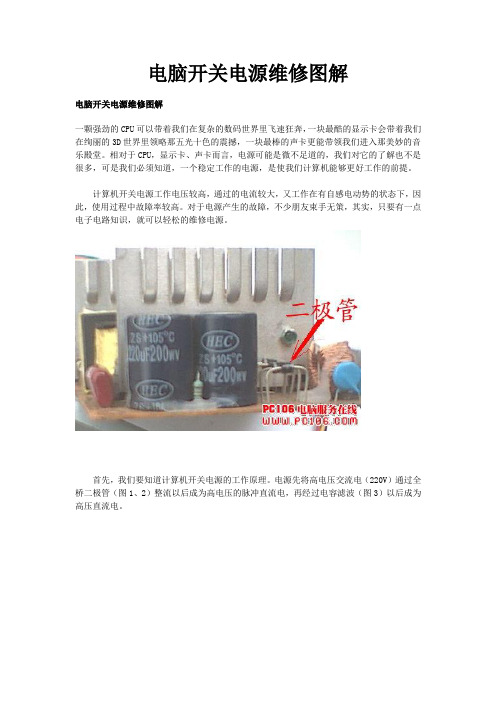
电源先将高电压交流电(220V)通过全桥二极管(图1、2)整流以后成为高电压的脉冲直流电,再经过电容滤波(图3)以后成为高压直流电。
此时,控制电路控制大功率开关三极管将高压直流电按照一定的高频频率分批送到高频变压器的初级(图4)。
接着,把从次级线圈输出的降压后的高频低压交流电通过整流滤波转换为能使电脑工作的低电压强电流的直流电。
其中,控制电路是必不可少的部分。
它能有效的监控输出端的电压值,并向功率开关三极管发出信号控制电压上下调整的幅度。
在计算机开关电源中,由于电源输入部分工作在高电压、大电流的状态下,故障率最高;其次输出直流部分的整流二极管、保护二极管、大功率开关三极管较易损坏;再就是脉宽调制器TL494的4脚电压是保护电路的关键测试点。
通过对多台电源的维修,总结出了对付电源常见故障的方法。
一、在断电情况下,“望、闻、问、切”由于检修电源要接触到220V高压电,人体一旦接触36V以上的电压就有生命危险。
因此,在有可能的条件下,尽量先检查一下在断电状态下有无明显的短路、元器件损坏故障。
首先,打开电源的外壳,检查保险丝(图5)是否熔断,再观察电源的内部情况,如果发现电源的PCB板上元件破裂,则应重点检查此元件,一般来讲这是出现故障的主要原因;闻一下电源内部是否有糊味,检查是否有烧焦的元器件;问一下电源损坏的经过,是否对电源进行违规的操作,这一点对于维修任何设备都是必须的。
开关电源的工作原理和故障维修

开关电源的工作原理和故障维修开关电源(英文:Switching Mode Power Supply),又称交换式电源、开关变换器,是一种高频化电能转换装置。
其功能是将一个标准的电压,透过不同形式的架构转换为用户端所需求的电压或电流。
▍简述开关电源是利用现代电力电子技术,控制开关管开通和关断的时间比率,维持稳定输出电压的一种电源,开关电源一般由脉冲宽度调制(PWM)控制IC和MOSFET构成。
随着电力电子技术的发展和创新,使得开关电源技术也在不断地创新。
目前,开关电源以小型、轻量和高效率的特点被广泛应用几乎所有的电子设备,是当今电子信息产业飞速发展不可缺少的一种电源方式。
随着电力电子技术的高速发展,电力电子设备与人们的工作、生活的关系日益密切,而电子设备都离不开可靠的电源,进入80年代计算机电源全面实现了开关电源化,率先完成计算机的电源换代,进入90年代开关电源相继进入各种电子、电器设备领域,程控交换机、通讯、电子检测设备电源、控制设备电源等都已广泛地使用了开关电源,更促进了开关电源技术的迅速发展。
开关电源和线性电源相比,二者的成本都随着输出功率的增加而增长,但二者增长速率各异。
线性电源成本在某一输出功率点上,反而高于开关电源。
随着电力电子技术的发展和创新,使得开关电源技术在不断地创新,这一成本反转点日益向低输出电力端移动,这为开关电源提供了广泛的发展空间。
开关电源高频化是其发展的方向,高频化使开关电源小型化,并使开关电源进入更广泛的应用领域,特别是在高新技术领域的应用,推动了高新技术产品的小型化、轻便化。
另外开关电源的发展与应用在安防监控,节约能源、节约资源及保护环境方面都具有重要的意义。
主要特点开关电源产品广泛应用于工业自动化控制、军工设备、科研设备、LED照明、工控设备、通讯设备、电力设备、仪器仪表、医疗设备、半导体制冷制热、空气净化器,电子冰箱,液晶显示器,LED灯具,通讯设备,视听产品,安防监控,LED灯带,电脑机箱,数码产品和仪器类等领域。
开关电源日常维护精选.ppt

.,
64
系统命名
P S 48 600-3 / 2900
整流模块额定功率 版本号 系统最大输出电流600A 系统输出电压48V 电源系统Power System
3
万用表测量数据为有效值
.,
4
直流
特点:电压、电流波形方向不变
ui
ui
U0 I0
U0 I0
t
稳恒直流电
t
脉动直流电
.,
5
整流电路
1、单相半波整流电路
2、单相桥式整流电路
.,
6
常用标示
.,
7
主要内容
➢ 电工根底回忆 ➢ 直流开关电源系统根本原理及
构造 ➢ 系统主要部件及功能
.,
8
系统命名
P S 4 8 300 / 25 - 100A
1000A75mv
.,
22
分流器
本质:精细电阻 作用:测量电流
300A75mv
分流器系数——用于 计算电流 分流器系数大小为300
.,
23
实物图
此分流器系数为300
.,
24
分流器系数的设定不可以设定错误,可以依照分流器上的钢 印值进展设定,如果设定错误会造成设备对电池进展过充或 电池充不满。
指示灯不全亮:
坏
.,
47
防雷器接线图
气体放电管击穿后电阻非常小,有几欧姆,正常时电阻在几千欧姆,在击 穿后,1、漏电2、用电量增大3、空开合不上。如果防雷空开跳闸,可 能零、火线接错。压敏电阻检查,用手检查插拔是否结实,窗口是否有 变化。压敏电阻处在高阻状态,当有高电压导通,通过PE引入保护地
电源维护培训手册

电源维护培训手册第一章电源维护基础知识1.1 电源的种类和原理电源是指将一种形式的电能转换为另一种形式的设备。
常见的电源种类包括直流电源和交流电源。
直流电源是指电流的方向始终相同,而交流电源则是指电流的方向随时间变化。
电源的工作原理是通过一定的电路和元件将电能进行转换和稳定,以满足不同设备对电能的需求。
1.2 电源的组成和结构电源通常由变压器、整流电路、滤波电路、稳压电路和保护电路等部分组成。
每个部分都有不同的功能,整体协同工作以提供稳定的电能输出。
1.3 电源维护的重要性电源作为设备的核心部分,其稳定性和可靠性对设备的正常运行起着至关重要的作用。
定期的维护可以保证电源的性能和寿命。
第二章电源维护方法2.1 定期检查和清洁定期检查电源的外观和内部结构,清除灰尘和杂物,保持电源通风良好。
2.2 测试电源输出用万用表等工具测试电源的输出电压和电流,确保输出符合设计要求。
2.3 定期维护和保养定期更换电源内部的电容器、电阻等易损件,以保证电源的稳定性和可靠性。
2.4 避免过载使用电源的额定功率是有限的,过载使用会损坏电源内部元件,降低电源寿命。
第三章电源故障排除3.1 电源故障的常见表现电源故障的常见表现包括输出电压不稳、有噪音、发热过高等。
定期检查可以及时发现这些问题。
3.2 故障排除步骤当发现电源故障时,应首先检查电源的外部连接和输入电压是否正常,然后逐步检查内部电路和元件,找出故障原因并修复。
3.3 注意事项在排除电源故障时,要注意安全,避免触电和短路,确保维修过程安全可靠。
第四章电源维护实例4.1 整流电路元件检查在定期维护中,需检查整流二极管、电容器和电阻的工作情况,是否有老化或损坏。
4.2 稳压电路调整如果发现稳压电路输出电压不稳定,可以进行调整和校准,以确保输出符合要求。
4.3 清洁和防尘电源内部往往积累了大量的灰尘和杂物,这些会影响散热和通风,导致电源工作不稳定。
定期清洁和防尘可以有效改善这种情况。
UniGearZS1操作及维护资料
ZS1铠装式金属封闭开关设备操作及维护始终安全第一在开关设备维护检修前请参阅本手册警告!始终遵守检修指导书规定和电气安全操作规程!危险电压可能引起电击和火灾!在装置上进行任何工作前必须切断电源!开关设备只能安装在适合电气设备工作的户内场合确保由专职的电气人员来安装、维护和检修必须保证现场电气设备的联接条件和工作规程的适用与安全性有关本开关设备的一切操作,都要遵守本说明书的相关规定!不要超出开关设备在正常工作条件下的技术参数规定的负载!手册应放置在所有与安装、维护、检修有关的人员能方便取得的地方!用户的专职人员因对所有影响工作安全的事项负责,并正确管理设备如有疑问,我们将乐意为您提供进一步的技术资讯版权所有,禁止将本手册的全部或部分以任何形式提供给第三者。
我们保留对所提供资料的更改权利,需更改时,不另行通知。
一、《UniGear ZS1凯装式金属封闭开关设备产品说明书》二、《UniGear ZS1凯装式金属封闭开关设备安装使用说明书》三、《VD4 真空断路器产品说明书》四、开关柜的操作4.1 断路器从运行位置转检修位置的操作4.1.1 将断路器分闸;4.1.2 逆时针摇动手柄将断路器手车摇至试验位置 ( 约 20圈);4.1.3 开启断路器室门;4.1.4 掰开航空插头扣板,(见图4-1);将航空插头拔出,将插头挂在断路器手车面板上的固定螺栓,(见图 4-2 );图4-1 将航空插头拔出图4-2 将航空插头固定在断路器上4.1.5将服务小车插进并锁定在开关柜上,然后向后试拉小车,确认小车是否锁定,此时小车上的手杆应偏向右侧极限位置 (见图4-3 ) 。
服务小车上的四个手轮可用来调整小车平台的高度,使服务小车平台和水平隔板的高度保持一致;图4-3 服务小车上的手杆位置4.1.6 向内侧移动断路器手车横粱定位销,将手车移至服务小车上并认断路器手车已定位;4.1.7 向左扳动服务小车上的手杆解服务小车和开关柜的锁定,将服务小车从开关柜上移开。
APW WYOTT 1.5 kW 电源 操作指南说明书

Phone:+1 (307) 634-5801 Fax: +1 (307) 637-8071 Toll Free:+1 (800) 752-0863 Website: E-mail:*****************INSTALLATION ANDOPERATING INSTRUCTIONSINTENDED FOR OTHER THAN HOUSEHOLD USERETAIN THIS MANUAL FOR FUTURE REFERENCEP/N 8802715 11/08APW WYOTTP .O. Box 1829Cheyenne, WY 82003This equipment has been engineered to provide you with year-round dependable service when used according to the instructions in this manual and standard commercial kitchen practices.RCHDT SeriesDrop-In Hot & Cold PansModels: CHDT-2, CHDT-3, CHDT-4, CHDT-5 & CHDT-6APW Wyott takes pride in the design and quality of our products. When used as intended and with proper care and maintenance, you will experience years of reliable operation from this equipment. To ensure best results, it is important that you read and follow the instructions in this manual carefully.Installation and start-up should be performed by a qualified installer who thoroughly read, understands and follows these instruction.If you have questions concerning the installation, operation, maintenance or service of this product, write Technical Service Department APW/Wyott Foodservice Equipment Company, P .O. Box 1829, Cheyenne, WY 82003.SAFETY PRECAUTIONSBefore installing and operating this equipment be sure everyone involved in its operation are fully trained and are aware of all precautions. Accidents and problems can result by a failure to follow fundamental rules and precautions.The following words and symbols, found in this manual, alert you to hazards to the operator, service personnel or the equipment. The words are defined as follows:X X X X X X X X X X X X X X X X X X X X X X X X X X X X X X X X X X X X X X X X X X X X X X X X X X X X X X X X X X X X X X X X X X X X X X X X X X X X X X X X X X X X X X X X X X X X X X X X X X X X X X X X X X X X X X X X X X X X X X X X X X X X X X X X XX X X X X X X XCONTENTSSafety Precautions2 Electrical Specifications4 Features & Operating Controls 4 Precautions & General Information 5 Agency Listing Information5 Installation6 Operation11 Cleaning Instructions12 Troubleshooting Suggestions13 Maintenance Instructions14 Parts Lists & Exploded Views16 Wiring Diagram20 Warranty23 LOCATION OF DATA PLATE:The data plate for the Hot & Cold Pans is located on the right side of the control box.IMMEDIATELY INSPECT FOR SHIPPING DAMAGEAll containers should be examined for damage before and during unloading. The freight carrier has assumed responsibility for its safe transit and delivery. If equipment is received damaged, either apparent or concealed, a claim must be made with the delivering carrier.A) Apparent damage or loss must be noted on the freight bill at the time of delivery. It must then be signed by the carrier representative (Driver). If this is not done, the carrier may refuse the claim. The carrier can supply the necessary forms.B) Concealed damage or loss if not apparent until after equipment is uncrated, a request for inspection must be made to the carrier within 15 days. The carrier should arrange an inspection. Be certain to hold all contents and packaging material.Installation and start-up should be performed by a qualified installer who thoroughly read, understands and follows these instructions.ELECTRICAL SPECIFICATIONSFEATURES & OPERATING CONTROLS Temperature Control Hot OperationThis appliance is intended for use in commercial establishments only, and is intended to hold previously prepared food for human consumption. Food may be held either hot or cold. No other use is recommended or authorized by the manufacturer or its agents.Operators of this appliance must be familiar with the appliance use, limitations and associated restrictions. Operating instructions must be read and understood by all persons using or installing this appliance.For hot operation, the appropriate water level must be maintained at all times. Food must be kept in appropriate inserts. Never place food directly into the tank.Cleanliness of this appliance is essential to good sanitation. Read and follow all included cleaning instructions and schedules to ensure the safety of the food product.Disconnect this appliance from electrical power before performing any maintenance or servicing.DO NOT submerge this appliance in water. This appliance is not jet stream approved. Do not direct water jet or steam jet at this appliance, or at any control panel or wiring. Do not splash or pour water on, in or over any controls, control panel or wiring. Do not wash floor around this appliance with water or steam jet.Exposed surfaces of this appliance during hot operation can be hot to the touch and may cause burns.Do not operate this appliance if the control panel is damaged. Call your Authorized Wells Service Agent for service.The technical content of this manual, including any wiring diagrams, schematics, parts breakdown illustrations and/or adjustment procedures, is intended for use by qualified technical personnel.Any procedure which requires the use of tools must be performed by a qualified technician.This manual is considered to be a permanent part of the appliance. This manual and all supplied instructions, diagrams, schematics, parts breakdown illustrations, notices and labels must remain with the appliance if it is sold or moved to another location.This appliance is made in the USA. Unless otherwise noted, this appliance has American sizes on all hardware.PRECAUTIONS AND GENERAL INFORMATIONThis appliance is performance tested to NSF Standard 4 for holding hot foods. This appliance conforms to NSF Standard 4 for sanitation only if installed in accordance with the supplied Installation Instructions and maintained according to the instructions in this manual.This appliance performance tested to NSF Standard 7 for storage of potentially hazardous foods. This appliance meets NSF Standard 7 only when pan rails are installed in the lowest position.Components used in the manufacture of this unit are Underwriters Laboratory recognized.AGENCY LISTING INFORMATIONSTD 4STD 7INSTALLATIONUNPACKING & INSPECTIONCarefully remove the appliance from the carton. Remove all protective plastic film, packing materials and accessories from the appliance before connecting electrical power or otherwise performing any installation procedure.Carefully read all instructions in this manual and the Installation Instruction Sheet packed with the appliance before starting any installation.Read and understand all labels and diagrams attached to the appliance.Carefully account for all components and accessories before discarding packing materials. Store all accessories in a convenient place for later use.COMPONENTS(2 Ea.) Pan Rail, Side(2 Ea.) Pan Rails, End(1 - 5 Ea.) Pan Rails, Intermediate ( Qty Differs With Unit)(1 Ea.) Drain Screen(1 Ea.) Backflow Preventer Assembly(1 Ea.) Drain Valve PREPARATIONCutout dimensions for tank units and control panels are listed on the Installation Instructions provided with the unit.Countertop must be flat and level before the unit is installed. After cutout is made, add stiffeners or bottom braces to counter as required to support unit weight.Provide louvered grills and service access below control panel.Verify that provided sealants are applied to the underside of the top flange prior to setting the unit into the cutout.After installation, apply a thin bead of food-grade silicone sealant around the flange to seal it to the counter.ELECTRICAL INSTALLATION1. Refer to the nameplate. Verify the electrical service power. Voltage and phase must match thenameplate specifications. Wiring the unit to the wrong voltage can severely damage the unit or cause noticeably decreased performance.2. Available electrical service amperage must meet or exceed the specifications listed on thespecification sheet provided with the unit. Connect to the terminal block in the control unit. Wiring must be secured to the control unit with an appropriate strain relief (provided by installer).IMPORTANT:* L1 to L2 must be 208 to 240 volts AC.* L2 to Neutral must be 120 volts AC3. Tank and control unit must be connected to an appropriate building ground. Ground connection willbe marked “GND” or “ G” .NOTE: Wire gauge, insulation type and temperature rating , as well as type, size and construction of conduit, must meet or exceed applicable specifications of local codes and of the National Electrical Code.PLUMBING INSTALLATIONIMPORTANT:All plumbing installations must be performed by a qualified plumber.NOTE:Plumb connections must be made in compliance with all Federal, State and Local Plumbing Codes and Ordinances.NOTE:All water line connections are made OUTSIDE of the control unit.1. Install provided 1" drain valve on unit drain. Plumb to an appropriate waste as required by localplumbing and sanitation ordinances.2. Install provided backflow preventer assembly to the tank water inlet. Attach water outlet tubing fromwater connection (located on bottom left of control unit) to the inlet of the backflow preventer.NOTE:While a backflow preventer is incorporated into the unit, local codes may require an additional backflow preventer or vacuum breaker in the water inlet line.3. The unit must be connected to a potable cold water supply line with average pressure between 20PSI and 90 PSI. If your water pressure exceeds 90 PSI at anytime, a pressure regulator must be installed in the water supply line to limit the pressure to not more than 90 PSI in order to avoid damage to lines and solenoid. Install water supply to inlet fitting (located on left side of control unit) with a 1/4" female flare.4. A water shut-off valve should be installed on the incoming water line in a convenient location (Use alow restriction type valve, such as a 1/4-turn ball valve, to avoid loss of water flow thru the valve.5.Test the operation of the autofill in the HOT operation mode.7.MINIMUM CLEARANCE REQUIRED FROMOPERATIONHOT OPERATION1. Verify that drain valve is CLOSED, the DRAIN SCREEN is in place, and the ELEMENT COVER isproperly positioned over the heating element.2. Turn SELECTOR SWITCH to HOT. The red HOT indicator will glow and the tank will begin filling withwater.3. Set the TEMPERATURE CONTROL to the desired temperature. When the water in the tankreaches the minimum water level the heating elements are energized and the water will begin heating. The HEAT indicator will glow while the unit is heating.a. Temperature range is (OFF) - 85ºF to 205ºF.b. When the HEAT indicator goes out, the water in the tank is up to the set temperature.4. Install the pan rails.a. Side rails are installed first. For normal hot operation, install the side rails on the upper pan railsupports.b. Install the end rails, then any intermediate rails.5. Install pans or insets on the pan rails.IMPORTANT: Always use a pan or inset.Never place food directly into the tank.6. Cover pans and insets to maintainconsistent temperature. Stir thick foodsfrequently.SHUT DOWN PROCEDURE1. Turn SELECTOR SWITCH to OFF.The red HOT indicator will turn off.2. Remove all pans and insets.3. Open drain valve.COLD OPERATION1. Verify that drain valve is OPEN, and the ELEMENT COVER is properly positioned over the heatingelement. The tank must be dry.2. Turn SELECTOR SWITCH to COLD. The white COLD indicator will glow. When the tank cools to100ºF or less, the refrigeration system will start.3. The temperature is factory set to NSF 7 required of 33ºF - 41ºF.4.Install the pan rails.a. Side rails are installed first. For normal cold operation, install the side rails on the upper pan railsupports. For holding potentially hazardous foods, install the side rails on the lower pan rail supports.b.Install the end rails, then any intermediate rails.5. Install pans or insets on the pan rails.IMPORTANT: Always use a pan or inset. Never place food directly into the tank.IMPORTANT: For NSF 7 operation, use12" x 20" x 4" deep pans, and use the lowerpan rail supports which are recessed 3" from tank top.SHUT DOWN PROCEDURE1. Turn SELECTOR SWITCH to OFF.The white COLD indicator will turn off.2. Remove all pans and insets.CLEANING INSTRUCTIONSPREPARATIONS: Turn temperature control knob and selector switch to OFF. Allow tank to cool beforeproceeding. Remove any insets, pans and/or adapter tops ( if used). Drain water from tank.FREQUENCY: DailyTOOLS: Warm Water and Mild Detergent Solution: 10 Parts Warm Water to 4 Parts Vinegar, Plasticscouring Pad, Clean Cloth or Sponge, Food-Grade Silicone Sealant.1. Remove pan rails, element cover and drain screen. Wipe interior of tank using a clean cloth or sponge and mild detergent.2. Use a plastic scouring pad to remove any mineral deposits from water level probes.3. Rinse tank thoroughly with a vinegar and water solution to neutralize all detergent/cleanser residue.4. Pan rails and element cover may be washed in a sink or dishwasher. Allow to dry thoroughly, then reinstall.5. Check drain screen, clean if necessary and reinstall.6. Periodically inspect warmer flange-to-counter seal. Reseal with food-grade silicone sealant if necessary.7. Inspect tank and control panel for damage. Contact your Authorized APW Wyott Service Agency for repairs if water or grease contamination is suspected.8.Inspect cooling louvers in counter. Remove any lint or debris. (Procedure is complete)TROUBLESHOOTING SUGGESTIONSMAINTENANCE INSTRUCTIONSCARE OF STAINLESS STEEL1. The surface can be damaged by mechanical abrasion, hard water deposits and chlorine:a.NEVER use steel wool, wire brushes or metal scrapers to clean the appliance. These willdamage the surface.b. Hard water deposits left behind when water is evaporated will attack the surface and allow thestainless steel to rust.c. Chlorides from chlorinated cleansers, calcium / lime / rust removers (e.g. muriatic acid), evenheavily chlorinated city water will attack the surface and allow the stainless steel to rust.d. DO NOT use any highly caustic cleaners. Use of highly caustic cleaners will damage thesurface.e. LIMIT USE of strong caustic cleaners on warmers. Rinse thoroughly with a vinegar and watersolution to neutralize any residue. Failure to do so may cause damage to the surface and allowthe stainless steel to rust.f. Cleansers containing ammonia will attack the surface and allow the stainless steel to rust.2. Use the proper tools in the proper way to clean your Wells warmer:a. Soft cloth and plastic scouring pads are safe to use on stainless steel surfaces.b. Stainless steel pads may be used ONLY IF the scrubbing motion is in the direction of the visiblegrain. DO NOT use a circular motion.c. In the absence of visible grain, use only soft cloth or plastic pads. Scrub only in a linear motionalong the longest axis of the equipment.3. Use only non-chloride and non-ammonia cleansers:a. DO NOT use any cleanser listed as “chlorinated”.b. DO NOT use any cleanser listing “ammonia” or “ammonium” in its contents.c. Contact your cleaning materials supplier for suitable alkaline cleansers.4. Keep your APW Wyott hot and cold pan clean. Clean frequently to avoid build-up of hard, stubbornstains and hard-to-remove deposits:a. Rinse thoroughly with a vinegar and water solution to neutralize any residue.b. For discoloration caused by using the warmer in dry operation, use a cleaner made specificallyfor stainless steel.c. Wipe dry with a soft, clean, dry cloth.d. Restore the surface by using a polishing product specifically made for stainless steel after eachcleaning.5. In areas where tap water has a high mineral content, warmers may develop lime deposits. Use anon-chloride de-liming agent to remove lime deposits. It is important to use Lime and Scale Cleaner for Warmer Pans often to prevent a difficult-to-remove build-up of lime deposits.LIME AND SCALE CLEANER INSTRUCTIONSAPW Wyott Lime and Scale Cleaner for Warmer Pans (instructions modified for use in Hot and Cold Pan) NOTE: Perform weekly, or whenever lime or scale is seen accumulating on the sides of the tank.1. Add water to tank until water is at normal operating level or until water covers accumulated scale.2. Turn SELECTOR SWITCH to HOT. Heat water to maximum temperature (190ºF or higher).3. For CHDT-2, use two packages, -3 use 3 packages, -4 use 4 packages, -5 use 5 packages, -6 use 6packages:Pour contents packages into tank. Stir to dissolve cleaner. Cover tank.4. Allow solution to soak at least one hour, or overnight for heavy scale buildup.5. After soak period, turn control to OFF position.6. Drain hot water from pans. Scrub with a plastic scouring pad. Rinse thoroughly with hot water thendry.7. Refill tank and resume operation.8. Heavy scale buildup may require additional treatments.CONDENSER COIL CLEANING INSTRUCTIONSThe condenser coil must be kept clean to allow adequate air flow for proper heat dissipation. Recommend this procedure be performed monthly.1. Turn selector switch to OFF. Disconnect appliance from electrical power.2. Remove louvers or access panel to allow coil to be reached.3. Using a stiff bristle brush, brush lint and debris from the condenser fins. Brush vertically, top tobottom. Collect and discard all lint and debris gathered from this operationIMPORTANT: The fins of the condenser coil are delicate and easily damaged. Use care to brush only in a vertical motion to avoid damaging the coil fins.4. Wipe the fan blades to remove accumulated lint.95. Reconnect to electrical power. Refer to COLD Operation (page) and test for proper operation.PARTS LISTS w/EXPLODED VIEWSWIRING DIAGRAMRPhone:+1 (307) 634-5801Fax: +1 (307) 637-8071Toll Free:+1 (800) 752-0863 APW WYOTT。
电源保护器操作手册说明书

Contentseg a Pn o i t p i r c s e D Introduction ..............................2Ins tallation ..............................3Manual Operatio n .........................4Inspection and Field Che cks .. (6)Installation Instructions for Series C F-FrameMotor Circuit Protector Type HMCP & HMCPS.............Installation Instructions for Series CF-Frame Instruction Leaflet IL 29C401KMotor Circuit Protector Type HMCP & HMCPSE ective December 20132EATON CORPORATION 3Instruction Leaflet IL 29C401KInstallation Instructions for Series C F-Frame Motor Circuit Protector T ype HMCP & HMCPSEATON CORPORATION E ective December 20134Instruction Leaflet IL 29C401KE ective December 2013Installation Instructions for Series CF-FrameMotor Circuit Protector Type HMCP & HMCPSEATON CORPORATION 5Instruction Leaflet IL 29C401KInstallation Instructions for Series C F-Frame Motor Circuit Protector T ype HMCP & HMCPSEATON CORPORATION E ective December 2013Instruction Leaflet IL 29C401K E ective December 2013Installation Instruction for Series CF- Frame Motor Circuit Protector Type HMCP & HMCPSEATON CORPORATION 67Instruction Leaflet IL 29C401KInstallation Instructions for Series C F-Frame Motor Circuit Protector T ype HMCP & HMCPSEATON CORPORATION E ective December 2013Instruction Leaflet IL 29C401K Installation Instructions for Series C F-FrameMotor Circuit Protector T ype HMCP & HMCPSEaton CorporationElectrical Group1000 Cherrington ParkwayMoon Township, PA 15108United States877-ETN-CARE (877-386-2273)© 2013 Eaton CorporationAll Rights ReservedPrinted in Dominican Republic Publication No. IL 29C401K/ TBG000464 Part No. 6620C47H10December 2013Eaton is a registred trademark of Eaton Corporation.All other trademarks are property of their respective owners.The instructions for installation, testing, maintenance, or repair herein are provided for the use of the product in general commercial applications and may not be appropriate for use in nuclear applica-tions. Additional instructions may be available upon request to replace, amend, or supplement these instructions to qualify them for use with the product in safety-related applications in a nuclear facility.The information, recommendations, descriptions, and safety nota-tions in this document are based on Eaton’s experience and judg-ment with respect to R tting of Power Breakers. This instruction-al literature is published solely for information purposes and should not be considered all-inclusive. If further information is required, you should consult an authorized Eaton sales representative.The sale of the product shown in this literature is subject to the terms and conditions outlined in appropriate Eaton selling policies or other contractual agreement between the parties. This literature is not intended to and does not enlarge or add to any such contract. The sole source governing the rights and remedies of any purchaser of this equipment is the contract between the purchaser and Eaton. NO WARRANTIES, EXPRESSED OR IMPLIED, INCLUDING WARRANTIES OF FITNESS FOR A PARTICULAR PURPOSE OR MERCHANTABILITY, OR WARRANTIES ARISING FROM COURSEOF DEALING OR USAGE OF T RADE, ARE MADE REGARDINGTHE INFORMATION, RECOMMENDATIONS, AND DESCRIPTIONS CONTAINED HEREIN. In no event will Eaton be responsible to the purchaser or user in contract, in tort (including negligence), strict liability or otherwise for any special, indirect, incidental or conse-quential damage or loss whatsoever, including but not limited to damage or loss of use of equipment, plant or power system, costof capital, loss of power, additional expenses in the use of existing power facilities, or claims against the purchaser or user by its cus-tomers resulting from the use of the information, recommendations and description contained herein.。
英特吉开关电源维护操作手册(精简版).(DOC)
英特吉开关电源维护操作手册福建移动通信责任有限公司2006年6月目录第一章英特吉开关电源基本原理一、简介二、英特吉电源系统1.交流配电模块2.直流配电模块3.低压脱离模块(LVD)4.整流器5.监控模块SM50第二章英特吉开关电源基本面板图形一、英特吉开关电源机柜二、英特吉开关电源整流模块1.R2948整流模块2.R2948整流模块前面板3.E2730整流模块前面板三、英特吉开关电源SM50 监控器1.SM50 监控器2.SM50监控器指示灯和接口第三章英特吉开关电源参数设置一、参数设置一(施威特系列)二、参数设置二(INTERGY系列)1.SM50监控器菜单2.调整对比度3.安全级别及密码第四章英特吉开关电源故障排除一、电源故障分析一(施威特系列)二、电源故障分析二(INTERGY系列)三、整流器装卸操作程序(INTERGY系列)第五章英特吉开关电源维护规程细则一、巡检目的二、月度巡检项目三、年度巡检项目第一章英特吉开关电源基本原理一、简介本章主要阐述英特吉电源系统(IPS)的基本原理和性能特点及各模块之间的内在关系,其中包括:英特吉电源系统、配电、低压脱离模块、整流器、监控模块SM50。
二、英特吉电源系统IPS8000/IPS7000系列电源系统是复合式机架电源,按进出线方式分,机架共有两种类型,他们是上进下出线和下进下出线。
对于上进上出线系统而方言,上部为交直流配电单元,下部为整流单元及监控单元,对于下进下出线系统而言,下部为交直流配单元,上部为整流单元及监控单元。
本将简述的模块有:●交流配模块●直流配电模块●低压脱离模块(LVD)●整流器●监控模块(SM50)●配置编辑器(软件模块)。
下图为IPS功能框图,显示不同的功能模块是如何相互联连而构成完整的英特吉电源系统。
IPS功能框图配电配电包括供电到整流器的交流输入配电及从整流器到负载或电池的直流输出配电。
在IPS中,有两个模块控制配电(打开带锁的门或直接在面板上就可以操作):1.交流配电模块交流配电模块给整流器提供交流输入电源。
(整理)开关电源操作手册

开关电源操作手册因部分开关电源(爱默生、中达、中兴、北京动力源、托普)参数设置不准确和监控单元显示数值与实际情况有偏移等问题,使基站蓄电池长期处于过充、欠充、过放等情况,导致后备电源不足当市电中断后,频繁发生因电源问题产生的大面积断站等严重事故。
因以上述技术隐患问题,我部门针对现网基站开关电源设备参数设置按基站重要层次分为三种:传输节点(3个以上)、VIP、普通站。
参数设置如下:一、基本要求:1、蓄电池均/浮充电压请按现场蓄电池端电压采样为准。
2、蓄电池容量根据现场实际蓄电池容量设置。
3、根据交流供电环境决定周期均充时间设置,正常交流供电环境设置3个月或100天一次;市电停电频繁的基站均充设置40-60天一次。
二、具体要求:传输节点站:均充 28.2V浮充26.8V155/622传输备:一次下电:23V2.5G:一次下电:23.5V二次下电:21.6VVIP基站:均充 28.2V浮充26.8V155/622传输备:一次下电:23V2.5G:一次下电:23.5V二次下电:21.6V普通基站:均充 28.2V浮充26.8V一次下电:23V二次下电:21.6V注:普通站一二次下电请根据实际蓄电池情况作相应调整三、操作手册针对现网使用开关电源(爱默生、中达、中兴、北京动力源、托普)以中达MCS_3000为例:本系统监控单元采用全智能化设计,内装微处理器,全数字化指示与调整,监控系统输入输出,整流模块状态、电池及环境温度、充放电控制与异常状况的告警与指示。
备有RS-232接口,具有遥讯、遥测、遥控功能,符合无人值守与集中监控的需要。
外接PC机采用中文窗口环境操作,可配合打印机提供系统文字信息,亦具有传呼机告警功能,能将主要告警通知用户,使用户随时获得系统最新信息。
监控单元与整流模块间以信号线联机。
它收集由整流模块传来的告警信号及电流值。
并可对整流模块下达停机、浮充/均充控制及浮充电压温度补偿的电压修正指令,下图为水平式监控单元外观图。
开关电源修理

开关电源修理推荐文章电脑开关电源的修理妙招与方法热度:开关电源检修技巧有哪些热度:开关电源维修方法热度:怎么更换台式电脑主机开关电源热度:怎么更换电脑主机开关电源热度:开关电源维修步骤。
说起开关电源,相信我们都不陌生,那开关电源有时候在使用中也会或多或少的出现一些小问题或者故障,那就需要我们及时检测出故障,并且进行开关电源维修。
虽然开关电源电路有易有难,功率有大有小,输出电压多种多样,但是按照店铺总结的以下内容,应该可以达到事半功倍的效果。
开关电源维修共有以下六个步骤:开关电源维修步骤1、修理开关电源时,首先用万用表检测各功率部件是否击穿短路,如电源整流桥堆,开关管,高频大功率整流管;抑制浪涌电流的大功率电阻是否烧断。
再检测各输出电压端口电阻是否异常,上述部件如有损坏则需更换。
开关电源维修步骤2、第一步完成后,接通电源后还不能正常工作,接着要检测功率因数模块(PFC)和脉宽调制组件(PWM),查阅相关资料,熟悉PFC和PWM模块每个脚的功能及其模块正常工作的必备条件开关电源维修步骤开关电源维修步骤。
开关电源维修步骤3、然后,对于具有PFC电路的电源则需测量滤波电容两端电压是否为380VDC左右,如有380VDC左右电压,说明PFC模块工作正常,接着检测PWM组件的工作状态,测量其电源输入端VC,参考电压输出端VR,启动控制Vstart/Vcontrol端电压是否正常,利用220VAC/220VAC隔离变压器给开关电源供电,用示波器观测PWM模块CT端对地的波形是否为线性良好的锯齿波或三角形,如TL494CT端为锯齿波,FA5310其CT端为三角波。
输出端V0的波形是否为有序的窄脉冲信号。
开关电源维修步骤4、在开关电源维修实践中,有许多开关电源采用UC38××系列8脚PWM组件,大多数电源不能工作都是因为电源启动电阻损坏,或芯片性能下降。
当R断路后无VC,PWM组件无法工作,需更换与原来功率阻值相同的电阻。
Lynergy电源电热器操作与维护手册说明书
Installation, Operation & Maintenance Manual forthe Lynergy Electric Heat with Discharge Temperature LimitContentsPageIntroduction ............................................................. 1 General .................................................................... 1 Inspection ................................................................ 1 Preparation .............................................................. 1 Operation ................................................................. 2 Troubleshooting .. (4)IntroductionLynergy is a patented (USPN 7,177534) electronic, time proportional electric heat system. The heat output of the heater is modulated utilizing quiet, rapid performing solid state relays. The relays are switched off and on to allow the heating of electrical resistance elements. Theproportion of time the relay is on dictates the proportion of maximum heat the electric heater can produce. The solid state relays are switched off and on by a supplied Electric Heat Module (EHM). The EHM accepts an input signal from the terminal unit controller or thermostat for theamount of heat desired. The EHM can accept a variety of different input signals when interfacing with controls. The type of input the EHM will accept is modified by changing the position of one to three jumpers easily accessible on the board.The Lynergy is available with an optional dischargetemperature sensor. When used with the discharge sensor option, the Lynergy will modulate outgoing temperature from the unit between the maximum temperature setting and initial temperature of incoming air before heating began. The discharge temperature set point is easilyadjusted in the field by rotating the temperature dial on the EHM. The EHM will not allow temperatures over the set point so as to prevent overheating, stratification, and energy waste from heated air lost through overhead returns.Additional information may be found at the Titus website, .GeneralThe following information is to be used by the installer as a guide. Since each installation is unique unto itself, only general topics are covered. Topic order may not be the same as required by actual installation.This guide is not intended to supersede or circumvent any applicable national, state or local codes.The installation is to be performed only by individuals whose experience meets or exceeds the requirements of the work involved.The installer MUST read the entire contents of this guide and develop a thorough understanding before beginning installation.Due to a continuing program of product research,Titus reserves the right to discontinue or change without notice, any or all specifications or designs without incurring obligations.InspectionThoroughly inspect all packages upon receipt. Ensure carton(s) have not been dropped, crushed or punctured. Inspect all contents for damage. If damage is found, immediately file a claim with the delivering carrier.PreparationUnpack Lynergy and check contents against the Bill of Materials.Review all submittal drawings and verify that all components have been delivered.Store all components in a clean and secure area.OperationInput SettingThe Lynergy board is capable of being controlled and operated 10 different ways. The units are ordered with an LXY code, where “X” is coded for unit power and “Y” is coded for the application. This “Y” application can be changed in the field. The application desired is chosen by placement of jumpers in the corner of board. Jumper settings below are representative of pins at bottom right of control board as shown in drawing. Wiring diagrams for each are on pages 6 & 7.On/Off: This application accepts one 24 Vacinput at Out 1 to step the heater output fromOFF to 100% heater kW rating. The signalmay be pulsed off and on over a small timeperiod to provide proportional heat. Forexample, a signal that is on for 4.5 secondsevery 10 seconds would produce 45% of theheater’s kW rating. This is the default value forLX1 heat.2 Stage (2Stg): This two stage applicationaccepts two 24 Vac inputs to step the heateroutput from off to 50% or 100% heater kWrating. This is the default value for LX2 heat.0-10V: This application accepts a 0-10 Vdc (0-20mA) signal to modulate the heater output.The output is proportional to input signal (i.e.,4.5 volts sets the heater to 45% of kW rating).This is the default value for LX3 heat.2-10V: This application accepts a 2-10 Vdc (4-20 mA) signal to modulate the heater output.The output is proportional to input voltageabove 2 volts (i.e., 4.5 volts sets the heater to25% of kW rating). This is the default value forLX4 heat.3 Point Floating (FLT2): This floating inputapplication accepts two 24 Vac inputs toincrease or decrease the heater output. Aseither an increase or decrease signal is sent,the heater output will change at a rate of 1%per second. When no change is called, theheater output remains constant at the value ofthe last call. This is the default value for LX7heat.Thermostat (Incr): This application acceptsone 24 Vac input to modulate heater output.An output signal will increase the heater output1% per second. When the output is off, heatdecreases at a rate of 1% per second. This isthe default value for LX5 heat.Binary (B2): This application accepts two 24Vac inputs to step the heater from off to 33%,67%, or 100% of the heater’s kW rating. Thisis the default value for LX6 heat.WiringThe EHM control board is powered by 24Vac (1) from thetransformer in the electric heater. The EHM has auxiliary24Vac outputs (2) that can be used to power the unit’selectrical controls. Next to the “Xfmr” inputs are the “+” and“-“ Relay connections (3) that control the solid state relaysby sending pulses of ~25Vdc.There are two terminations to use for dc Volt control (4) ofthe electric heat (applications LX3 and LX4 from above).These are polar sensitive. The “+” signal from the controllermust be connected to “Signal” on the EHM Control Board.The “-“ from the controller must be connected to “Com” nextto “Signal (Note: NOT “iCom”). A termination to “-“ ispossible, but not necessary to measure mA signals to theboard.There are three terminations for 24 Vac control (5) of theelectric heat (applications LX1, LX2, LX5, LX6, and LX7from above). “Inc” is for the increase signal in applicationsLX5 and LX7, as well as the first stage heat signal inapplications LX1, LX2, and LX6. “Dec” is for the decreasesignal in application LX7, as well as the second stage heatsignal in applications LX2 and LX6. A connection to “iCom”is necessary for all of these 24 Vac applications. If theunit’s controller does not have a Common output, a jumperto the correct “Aux” terminal can be used. If the unitcontroller outputs the “24Vac” side from it’s input power, ajumper should be made from “Neutral” to “iCom” (Seesample diagram on page 7). If the unit controller outputsthe “Neutral” side of it’s input power, a jumper should bemade from “24Vac” to “iCom”.Discharge Temperature Set PointLynergy comes with a discharge temperature set point (DTS) option. This option allows a maximum temperature to be set at the board to prevent overheating of discharge air. When the unit receives a signal to start heating, the board will take an initial temperature reading and modulate heat from that point to the maximum temperature. For example, if a thermostat requires only a 10% heating output of air that was initially 60°F and has a maximum temperature setting of 90°F, the EHM will modulate the heater’s output temperature to 63°F (the additional 3 degrees coming from (90-60)*10%). This allows heaters to be sized for morning warm up in the winter and still comfortably operate on those days when the inlet temperatures are slightly warmer.The discharge temperature sensor comes with a 9’ cable for mounting in the downstream ductwork. The sensor should be mounted a minimum of 36” from the discharge of the unit and be vertically centered in the ductwork. The sensor can be mounted by drilling a 1/2” hole into the ductwork, inserting the sensor, and securing it with 2 sheet metal screws. The sensor is 6” long, and the tip should not touch any part of the ductwork.Neither the jumper settings nor the controls wiring needs to be changed when this option is ordered. The EHM control board will detect if a sensor has been connected, and it will adjust the control function accordingly. The sensor wires areconnected to the screw terminals at the “Sensor” (6) location on the EHM. The connection at this termination is not polar sensitive and the two wires may be switched with no effect. The desired discharge temperature is set by rotating the discharge temperature set point dial arrow to the maximum outlet temperature desired. To fine tune the dischargetemperature set point, connect the positive and negative leads of a multi-meter to “Tcal” and “Com” (7), respectively, on the EHM. Then place a jumper between the two screw heads on the sensor termination. Rotate the discharge temperature set point dial until the desired voltage per temperature isobtained. After the voltage is obtained, the EHM board must be reset. To reset the board, remove the jumpers and then place back in correct position.TroubleshootingProblem: No heat when called for1. Confirm the jumper setting is correct for the input given.2. If the controls are outputting Vdc, the jumper should be set as shown on page 2 for applications LX3, and LX4.3. If the controls are outputting 24Vac, the jumper setting should be set as shown on page 2 for applications LX1, LX2,LX5, LX6, & LX7. (Also see diagrams on page 6 & 7)4. Check that wiring to the EHM is correct.5. If using applications LX3 and LX4, confirm the positive Vdc connection is wired to the “Signal” terminal, and thenegative Vdc connection is wired to the “Com“ terminal.6. If using 24Vac, confirm the wires are terminated correctly at (5) with a connection at “iCom”. If an “Aux” terminal (2) onthe EHM has been jumpered to “iCom”, make sure that the opposite 24Vac input is what is outputted at the controls.7. Check that airflow is above minimum. Terminal units with electric heat come with pressure switches to insure thatheater elements have airflow over them. See catalog for minimum airflow required for specific size terminal units. Fan boxes must have minimum downstream static of 0.2”8. Check that discharge temperature setpoint is not below the airflow temperature.9. Check Relay wiring. Solid state relays are polarity sensitive. The wire from “+” on the EHM control board should beterminated on “+3” VDC terminal of the relay. The wire from “-“ on the EHM control board should be terminated on “4-“ VDC terminal of the relay. If there are two relays used in the heater, the relays are daisy chained from “4-“ to “+3”together.10. Check the potentiometer on the SSR control board to ensure that it is in the 100% position.Problem: Discharge Temperature not at Temperature Setting1. Check that wires from sensor are stripped and terminated in EHM control terminals.2. Check that wires from controls are terminated at the correct point on EHM board. Increase or stage 1 signal should beterminated at “Inc”. Decrease or stage 2 signal should be terminated at “Dec”.3. Check volt setting.4. Check sensor placement. Make sure that sensor is well placed vertically in ductwork and at least 36” from discharge.Sensor tip should not touch inside of ductwork.5. Try staging or ramping of output on oversized heaters. When controls call for full heat from cooling mode, if heatersare too large and heating times are small, the heater output may be over setpoint. Staging or ramping of output over a60 second interval will provide smooth transition. If only one output of heat is available from controls, application LX5will proportionally ramp heat output frm 0 to 100% over a 2 minute 1 second span.。
- 1、下载文档前请自行甄别文档内容的完整性,平台不提供额外的编辑、内容补充、找答案等附加服务。
- 2、"仅部分预览"的文档,不可在线预览部分如存在完整性等问题,可反馈申请退款(可完整预览的文档不适用该条件!)。
- 3、如文档侵犯您的权益,请联系客服反馈,我们会尽快为您处理(人工客服工作时间:9:00-18:30)。
英特吉开关电源维护操作手册目录第一章英特吉开关电源基本原理一、简介二、英特吉电源系统1.交流配电模块2.直流配电模块3.低压脱离模块(LVD)4.整流器5.监控模块SM50第二章英特吉开关电源基本面板图形一、英特吉开关电源机柜二、英特吉开关电源整流模块1.R2948整流模块2.R2948整流模块前面板3.E2730整流模块前面板三、英特吉开关电源SM50 监控器1.SM50 监控器2.SM50监控器指示灯和接口第三章英特吉开关电源参数设置一、参数设置一(施威特系列)二、参数设置二(INTERGY系列)1.SM50监控器菜单2.调整对比度3.安全级别及密码第四章英特吉开关电源故障排除一、电源故障分析一(施威特系列)二、电源故障分析二(INTERGY系列)三、整流器装卸操作程序(INTERGY系列)第五章英特吉开关电源维护规程细则一、巡检目的二、月度巡检项目三、年度巡检项目第一章英特吉开关电源基本原理一、简介本章主要阐述英特吉电源系统(IPS)的基本原理和性能特点及各模块之间的内在关系,其中包括:英特吉电源系统、配电、低压脱离模块、整流器、监控模块SM50。
二、英特吉电源系统IPS8000/IPS7000系列电源系统是复合式机架电源,按进出线方式分,机架共有两种类型,他们是上进下出线和下进下出线。
对于上进上出线系统而方言,上部为交直流配电单元,下部为整流单元及监控单元,对于下进下出线系统而言,下部为交直流配单元,上部为整流单元及监控单元。
本将简述的模块有:●交流配模块●直流配电模块●低压脱离模块(LVD)●整流器●监控模块(SM50)●配置编辑器(软件模块)。
下图为IPS功能框图,显示不同的功能模块是如何相互联连而构成完整的英特吉电源系统。
IPS 功能框图配电配电包括供电到整流器的交流输入配电及从整流器到负载或电池的直流输出配电。
在IPS 中,有两个模块控制配电(打开带锁的门或直接在面板上就可以操作):1.交流配电模块交流配电模块给整流器提供交流输入电源。
一个安装在交流输入上的空气开关,能使IPS 与交流输入电源隔离。
小型空气开关(MCB )保护连接各整流器的配电电缆,以防短路和过载,并且能隔离每台整流器。
在交流配电模块内装有防止电压冲击和浪涌的保护装置。
如果浪涌保护装置有故障,便有告警信号传给SM50。
2.直流配电模块直流配电模块将直流电源从整流器输送到负载和电池。
直流配电模块有两种类型:微型电路开关型(DCM)和熔断器型(DCF)。
DCM和DCF两者都是可用于隔离各负载和电池的电缆,并且保护他们以防过载。
如根据需要,低压脱离(LVD)模块可以安装在DCM模块中。
3.低压脱离模块(LVD)当长时间交流电故障,LVD模块保护电池,以防电池过放电。
当电池电压降到低于预设值时,LVD模块使用一个电磁离合器断开电池。
当电压升到高于预设值时,LVD模块重接电池。
可以将LVD连接成一个电池或负载的断路装置。
LVD模块可以在SM50的控制下自动运行,也可通过SM50前面板或直接在LVD模块上手动重接。
在操作过程中,LVD模块接收SM50发来的控制信号,并将其状态信号送回给SM50。
4.整流器器将交流电输入转换为直流电输出,向电池和负载供电。
交流输入是从外部交流供电通过交流配电模块获得。
每台整流器的输出都连接到汇流排上,并通过直流配电模块配电。
在整流器内部有一个微处理器,用来监视整流器状况及控制整流器输出参数。
整流器通过RS-485串行口连接到SM50上。
SM50发送命令给整流微处理器来改变整流器的操作参数。
当被查询时,微处理器将整流器信息送给SM50。
整流器安装在系统的整流器架中。
从IPS的正面将整流器插入整流器架背板的连接插座上。
每个整流器架可安插三台整流器。
整流器告警及运行状态均由前面板LED显示。
5.监控模块SM50监控模块监控IPS的运行,发布命令控制整流器及LVD的运行。
每个模块都被监视,一旦发生影响系统性能的故障,便触发告警器。
监控模块接收电流、电压和温度感应器的模拟量输入。
有六个用户配置数字输入和从IPS各模块来的数字输入,还有一个RS-232C串行口用来配置监控模块运行参数。
监控模块有十个继电器输出。
它们通常用于操作外部告警器。
两个附加的继电器输出用来控制LVD模块。
通过RS-485串行口与整流器之间传送控制命令和数据。
第二章英特吉开关电源基本面板图形一、英特吉开关电源机柜二、英特吉开关电源整流模块1.R2948整流模块特点:整流器后部有一个可直接插入、自我对齐的多针插头,用来输送交流、直流电源和告警、控制信号。
具有凸轮及折叠式把手以便整流器能平滑地插入整流器架中。
2.R2948整流模块前面板三个LED指示灯显示了整流器地基本状况:绿色代表接通电源红色代表紧急告警黄色代表一般告警。
3.E2730整流模块前面板三、英特吉开关电源SM50 监控器1.SM50 监控器2.SM50监控器指示灯和接口SM50 监控面板指示灯RS-232C接口该接口用于PC于SM50之间的连接,应用(电源管理)软件,如SPM3,来配置和控制SM50。
使用虚调制解调器电缆。
LED红色的LED指示经告警配置定义为(紧急)的告警。
黄色的LED指示经告警配置定义为(紧急)的告警。
第三章英特吉开关电源参数设置一、参数设置一(施威特系列)E40-27面板功能图1. 电流显示显示负载或电池电流(负的电池电流表示电池放电电流),单位为安培。
也用于配置模式或测试模式时显示。
2. 电池电流指示灯 Battery当“Load/Battery”按键按下时,此指示灯亮,并显示电池电流。
3. 声音报警指示当允许声音报警时,在液晶显示器的这个位置显示“ --”的标记。
4. 电压显示显示负载排上的电压,单位为伏特,也用于显示报警设定值以及在配置模式中显示设定的参数值。
5. 电池脱离指示灯 Battery Disconnected当电池脱离继电器闭合时灯亮。
6. 负载高压报警指示灯 Load High出现负载高压报警时灯亮。
7. 浮充高压报警指示灯 Float High出现浮充高压报警时灯亮。
8. 浮充低压报警指示灯Float Low出现浮充低压报警时灯亮(通常在交流进线出故障而由电池供电情况下出现)。
9. 负载低压报警指示灯 Load Low出现负载低压报警时灯亮。
10. 整流器故障指示灯 Rectifier Failed当任一整流器出现故障时灯亮。
11. 异常指示灯Off Normal在异常情况下此指示灯亮。
12. 电池测试指示灯在进行电池测试时,此指示灯亮。
13.监控器故障指示灯 Monitor Failed当监控器自测试失败时灯亮。
14. 均充指示灯Equalise当整流器进入均充状态时灯亮。
15. 熔断器故障指示灯 Fuse Failed当电池断路器或者直流配电模式块上的断路器断开时灯亮。
16. 进线故障指示灯 Mains Failed当三相交流电缺任一相时灯亮。
17. 负载/电池按键“Load/Battery”此键按下时显示电池电流(上面的LCD)18. LVD复位键(只在装有低压脱离装置的设备中起作用)“LVD Reset”此键按下后,已脱离的电池重新又连接到系统上。
19. 上升/打开按键“Up/On”此键按下,可调整报警门限值(当第20的“Alarm Select”被按下并保持时),也用在配置模式时选择各种各样的选项。
20. 报警选择键“Alarm Select”此键按下时就可以选择各种报警门限值进行调整,与第25的“Mode”键一起使用可显示温度。
21.下降/关闭按键“Down/Off”此键按下,可调整报警门限值(当第20的“Alarm Select”被按下并保持时),也用在配置模式中选择各种各样的选项。
22. 报警复位按键“Alarm Reset”按下此键就可返回到正常模式,或者用来关闭声音,还可以与“Mode”键一起使用,进入配置模式。
23. 测试按键“Test”与“Mode”键一起按下时就可以进入校正模式,单独按下即可开始电池测试。
注意:按下“Test”键进行电池测试时会关闭所有的整流器。
24. 均充按键“Equalise”按下此键就可以进行均充。
25. MODE按键“Mode”与“Alarm Select”一起按下时显示温度,与“Alarm Reset”一起按下时就进入配置模式,当进入配置模式后再一步一步按下此键,就可以选择配置模式中的各种选项。
注意:各地应根据实际情况设置。
二、参数设置二(INTERGY系列)1.SM50监控器菜单SM50菜单2.调整对比度3.安全级别及密码第四章英特吉开关电源故障排除一、电源故障分析一(施威特系列)1、整流器故障告警a.检查交流配电盘对应的输入MCB状态b.检查整流器交流输入MCB状态,可作多次开关机试验c.交流进线缺相或停电d.进入电池测试状态e.整流器故障2、浮充低压告警a.测量浮充电压,检查浮充低压告警值b.浮充低压值设置太高,温度补偿造成的电压波动引起告警c.整流器进入限流状态d.温度传感器EA55故障e.以上各项均正确的情况下,可能E40-27有问题3、进线故障告警a.市电不正常,有缺相或其他异常b.进线故障检测器问题c.监控器E40-27问题4、熔丝断告警a.负载熔丝或电池熔丝断b.电池熔丝未压到底,导致机械装置未起作用c.接了负载之后,熔丝或MCB未合上d.监控器E40-27问题5、异常告警a.整流器进入限流状态b.电池测试状态c.进入均充状态d.风扇故障e.监控器E40-27故障f.交流进线故障g.进入强充功能6、风扇故障a.灰尘等颗粒卡住风扇,可以拨动一下之后再试机b.风扇本身故障7、整流器过压关机a.整流器过压点设置太底b.整流器自身故障8、不能均充a.监控器E40-27内部均充设置状态关闭b.25芯扁平电缆未插入整流器c.有整流器故障告警,对应整流器的25芯扁平电缆未拔掉d.有进线故障告警不能均充e.B7 B8接反不能进行均充f.刚进行过监控器操作,未复位d.监控器E40-27故障9、整流器不能均流a.整流器浮充电压设置有差异b.25芯扁平电缆未插好c.25芯扁平电缆坏d.整流器损坏10、LVD不能正常工作a.监控器E40-27设置错误(注:有些型号LVD与监控器E40-27无关)b.LVD控制信号线接错c.LVD控制板有问题d.LVD接触器有机械故障(可先测线包电压来判断)e.监控器E40-27故障(未送出控制信号)11、E40-27故障a.电流值始终显示满量程值电流取样信号线没连或E40-27监控器的公共端没有连接正确(公共端为火线排)b.电压读数稍微有点误差电流和温度的取样线没有连接正确c.E40-27监控器显示“Err52”内部电池故障,让监控器继续工作,对电池充电48小时二、电源故障分析二(INTERGY系列)三、整流器装卸操作程序(INTERGY系列)注意:工程人员在往整流器架内安装整流器时,应注意以下事宜:确保所有整流器型号一致。
