2013 Thermal Runaway Containment and Thermal Management Using Phase Change Material (PCM)
关于锂电池温控集装箱运输 英语
关于锂电池温控集装箱运输英语$$Lithium Battery Temperature-Controlled Container Transportation$$The transportation of lithium batteries viatemperature-controlled containers has become increasingly critical in today's world, given the widespread usage of lithium batteries in various industries. Lithium batteries, being highly energy-dense and chemically reactive, require meticulous handling and strict temperature control during transportation to ensure their safety and performance. This article delves into the nuances of lithium battery temperature-controlled container transportation,highlighting its importance, challenges, and best practices. **Importance of Temperature Control in Lithium Battery Transportation**Lithium batteries are sensitive to temperature fluctuations. Exposure to excessive heat or cold can leadto battery degradation, performance issues, and even therisk of thermal runaway. Thermal runaway occurs when the internal temperature of a battery rises to a point where ittriggers a chain reaction, leading to a fire or explosion. Therefore, maintaining a stable and optimal temperature environment is crucial during the transportation of lithium batteries.Temperature-controlled containers are designed to maintain a constant internal temperature, either by heating or cooling, depending on the ambient conditions. This ensures that lithium batteries are transported within a safe temperature range, minimizing the risk of damage or malfunction.**Challenges in Lithium Battery Temperature-Controlled Container Transportation**There are several challenges associated with lithium battery temperature-controlled container transportation. One of the primary challenges is maintaining a consistent temperature throughout the entire journey. This can be particularly difficult when the container is exposed to varying ambient temperatures, such as during land transportation or when traversing different climatic zones. Another challenge is ensuring that the temperature control system is reliable and effective. The system mustbe able to respond quickly to temperature fluctuations and adjust the heating or cooling accordingly. It must also be energy-efficient to minimize the environmental impact of transportation.Safety is another crucial aspect of lithium battery transportation. The containers must comply with strict safety regulations, including those related to fire prevention and containment. This involves the use of fire-resistant materials, proper ventilation, and safety features such as automatic shut-off valves in case of temperature excursions.**Best Practices for Lithium Battery Temperature-Controlled Container Transportation**To ensure the safe and effective transportation of lithium batteries via temperature-controlled containers, several best practices should be followed.Firstly, it is essential to conduct a thorough risk assessment before transporting lithium batteries. This involves identifying potential hazards, such as temperature extremes or mechanical damage, and developing measures to mitigate these risks.Secondly, the temperature control system should be regularly inspected and maintained to ensure its optimal performance. This includes checking the heating and cooling elements, sensors, and any other related components.Thirdly, proper packaging and labeling of lithium batteries are crucial. Batteries should be securely packaged to prevent damage and labeled with clear instructions and warning labels. This information should include handling instructions, temperature limits, and emergency contact details.Fourthly, it is advisable to use experienced and qualified personnel for the transportation of lithium batteries. They should be trained in handling lithium batteries safely and be aware of the potential hazards associated with their transportation.Lastly, it is essential to comply with all relevant regulations and standards. This includes adhering to national and international regulations on thetransportation of dangerous goods, as well as any specific regulations related to lithium batteries.**Conclusion**In conclusion, lithium battery temperature-controlled container transportation is a complex yet crucial aspect of modern logistics. By maintaining a consistent and optimal temperature environment, we can minimize the risk of damage or malfunction during transportation. However, it is essential to follow best practices, conduct thorough risk assessments, and comply with all relevant regulations to ensure the safe and effective transportation of lithium batteries. As the demand for lithium batteries continues to grow, it is imperative that we continue to innovate and improve our temperature-controlled container transportation systems to meet this demand safely and efficiently.。
赛默飞世尔实验室炉子操作标准操作程序说明书

Laboratory Furnaces SOPSummary•There are various types of laboratory furnaces, including Tube, Box, and Muffle.•Because each unit is different, read the manual, complete safety training provided by your PI or trained senior colleagues. Only use a furnace that you fully understand how to operate.•Furnaces present electrical, fire, and burn hazards, and the insulation can pose a health hazard.Furnaces can also create inhalation health hazards if they malfunction and are not stored inappropriate containment, like a fume hood.•Regularly inspect your furnace for any loose or damaged wiring, physical defects, and water or heat damage.•Follow the safety guidelines outlined in this document, and contact the manufacturer if you have questions regarding specific use or servicing of your furnace.What are Laboratory Furnaces?There are many furnace varieties used in the laboratory. They are useful for chemical synthesis, curing ceramics, and are essential in materials science, engineering, food science, and geological research. Three of the most common units are Tube, Box, and Muffle furnaces. Of note, furnaces are similar to ovens, but they can operate at much higher temperatures (typically higher than 500⁰C).A Tube Furnace (Figure 1) consists of cylindrical chambers surrounded by heating elements, which enable rapid heat up, recovery, and cool down. It is typically suited for smaller (and inorganic) samples and heating in an inert atmosphere. Common applications include the purification, coating, drying, hardening, or ageing of samples. A tube furnace can also be used for annealing, brazing, calcination, degassing, sintering, soldering, sublimation, synthesis, and tempering. It is generally a good idea to place tube furnaces in a fume hood, however, the need for local exhaust is process dependent and should be determined through an appropriate risk assessment. EH&S generally recommends keeping furnaces in a fume hood or to provide some other form of local exhaust in case the units malfunction, which can produce burnt wiring and other inhalation hazards.A Box Furnace (Figure 2) features a vertical lift or swing out door allowing the various sized product(s) to be easily placed in the furnace. Box Furnaces are utilized for heat-treating, calcining, curing, annealing, stress relieving, preheating, tempering, and other high temperature thermal processes. The volatile material in a sample is burned off and escapes as a gas; therefore, these furnaces MUST be placed in a fume hood or containment must be provided by some other type of appropriate local exhaust (i.e., a canopy or snorkel hood).Muffle furnaces (Figure 3) are a subclass of Box Furnace: they are compact countertop heating sources with insulated firebrick walls to maintain high temperatures. They allow rapid high-temperature heating,recovery, and cooling in self-contained, energy-efficient cabinets. This is ideal for ashing samples, heat-treating applications, and materials research. Muffle furnaces use mechanical convection to direct airflow out of an exhaust muffle, and typically do not require placement in a fume hood (though it is recommended if possible in case the unit malfunctions).Figure 1. Tube Furnace. Figure 2. Box Furnace. Figure 3. Muffle Furnace.What are the Hazards?Extreme Temperature HazardsHigh voltage is needed to generate temperatures greater than 500°C. With high voltage comes inherent dangers of electrocution, fire, and severe burns. Make sure the furnace is properlygrounded and no loose wires are connected to the furnace, and wear all necessary protectiveclothing while operating (as outlined later in this document).The furnace program should be stopped, or the furnace shut off before opening the furnace door.Note that material will not always glow or appear hot, but will cause severe burns with improper handling.The elements for the furnaces may be exposed and can be easily damaged if bumped or scraped.They are very expensive to replace. The furnace elements are operated at a high current and can be dangerous if touched.Health HazardsMany laboratory furnaces contain refractory ceramic insulation, which can produce respirable fibers or dust with crystalline silica when handled. Crystalline silica may cause chronic lung injury (silicosis) after prolonged exposure or a heavy exposure in a short time. Silicosis is a form of disablingpulmonary fibrosis which can be progressive and may lead to death. The International Agency for Research on Cancer (IARC) reports sufficient evidence of carcinogenicity of crystalline silica tohumans. IARC classifies ceramic fiber as 2B (possible carcinogenic to humans). Older furnaces typically had insulation which contained asbestos. As such, it is also important to appropriately dispose of furnaces once they have passed their useful lifetime.What Activities Could Pose a Risk?•Using a box furnace that sits outside of a fume hood.•Opening/servicing your furnace unit without specified training.•Altering wiring, and altering or disabling the safety features, such as safety interlocks, sensors, etc.•Using common oven mitts, cryogenic gloves, or no gloves instead of thermal-rated glove protection.•Heating materials beyond their melting or decomposition points. Melting points (and occasionally decomposition points) can be found on a material’s SDS.•Using a malfunctioning furnace or having a furnace malfunction.•Heating sealed vessels in a furnace may result in an explosion if the vessels are not rated for the increased pressure or temperature.•Heating hazardous materials: Do not heat samples or glassware with chemicals that pose respiratory hazards. Evaporation in the furnace will release vapors into the atmosphere, where yourself or other lab members may breathe the toxic materials if the units are not appropriately contained in fume hood or provided with other appropriate local exhaust ventilation.How Can Exposures be Minimized?When working with any hazardous material orprocess, always conduct a thorough riskassessment and employ the hierarchy of controlsto minimize risk. Specific applications of thehierarchy of controls to the unique hazards oflaboratory furnaces are listed below. Apply thecontrols in the order of most effective to leasteffective (see graphic at right), and apply asmany controls as possible to reduce the risk tothe lowest achievable level.Elimination/Substitution•Avoid using a furnace for the sole purpose of cleaning glassware. Towel dry, air dry, or blow dry if possible.•Heat materials to the lowest possible temperature to reduce the severity of potential burns and furnace failure.•When purchasing a furnace, please consider purchasing those with safety features if possible.Engineering Controls•Work in a well-ventilated area. If heating hazardous materials and if the unit fits, put the furnace in a fume hood to ensure sufficient ventilation of escaping fumes. EH&S generally recommends that furnaces are operated in fume hoods or with other appropriate local exhaust ventilation in case the unit malfunctions, which can release hazardous gases into the occupied lab space.Administrative Controls•Before Use:o All furnace operators must complete safety training specific to the furnace they will work with.o Read the instrument’s manual thoroughly, and understand the oven’s capabilities, limitations, safety features and safety protocol. Always follow manufacturer protocoland recommendations.o Consult with the manufacturer and your PI to ensure that your planned experiments are appropriate for the unit. For instance, never overheat the materials or their containers:Borosilicate glass should not be heated above 400°C for short-term service, and Pyrexnot above 300°C. Always check the manufacturer’s recommended usable temperaturerange of containers prior to use in a furnace, and do not use containers for applicationsoutside of the range.o Though lab furnaces have internal safety circuits, consider attaching an external temperature controlled power circuit that would cut the power to the unit in the eventof elevated temperatures. Companies like McMaster Carr and Omega Engineeringprovide thermocouples and controllers that could be used to fabricate a cost-effectivecircuits of this kind.•Keep the furnace’s wiring tidy and away from other heat-generating sources. Damaged wiring could result in an electrical fire.•Never disable safety features. Only service units if permitted by the manufacturer.•Never heat a furnace to its maximum temperature.•Do not heat samples or glassware with chemicals that pose respiratory hazards unless the units are contained in a fume hood or provided with other appropriate local exhaust. Evaporation in the furnace will release vapors into the atmosphere, where yourself or other lab members may breathe the toxic materials if these are not appropriately contained.•Keep the area around the furnace decluttered. Items beside the furnace may get hot and melt, catch fire, boil, or explode.•Always place and remove items from the furnace with thermal-rated tongs or forceps.•Regularly inspect your furnace for any loose or damaged wiring, water and heat damage, or other visual defects. Contact the manufacturer or vendor directly for repairs and servicing.•Dispose of furnace units that are beyond their usable lifetime. Follow the process for laboratory equipment disposal described on the EH&S website.Personal Protective Equipment (PPE)•When working with a furnace, always wear long pants, closed-toe shoes, a lab coat, and safety glasses.•ALWAYS wear the appropriate thermal gloves, and regularly check them for rips, holes, or tears.All-cotton terrycloth gloves are sufficient protection for temperatures up to 232°C (i.e. autoclave use), but heat- or flame-resistant gloves are required when using furnaces at highertemperatures. It is recommended that a pair of such gloves is always available near a labfurnace, even when working with lower temperatures, in the case of thermal runaway. Visit the EH&S guide to glove selection for more information. If you need additional assistance inselecting appropriate gloves, please contact EH&S at ****************.Service RecommendationsRegularly inspect your furnace for any loose or damaged wiring, water damage, heat damage, or other visual defects. If something appears damaged, worn, or is malfunctioning, DO NOT begin/continue using the furnace – power off immediately. Contact the manufacturer or vendor directly for repairs and servicing. Dispose of units beyond their useable lifetime.Exposure and Spill ProcedureIn the event of a furnace incident or malfunction, immediately turn off and unplug the furnace if it is safe to do so. Evacuate the room and notify EH&S (413-545-2682) for assistance.After any emergency or near-miss circumstance, notify EH&S (413-545-2682) as soon as possible and complete the lab incident form.For an exposure:1.Dermal Exposure: In the event that exposed skin touches the hot oven or its contents,immediately rinse affected area with copious amounts of cool water for at least 15 minutes toreduce further tissue damage. For serious burns, call 911 (report the building name, roomnumber, and street address) or 413- 545-3111 (or simply 5-3111 from a campus line) to report the incident and request medical help. For minor burns, immediately go to UHS.2.Inhalation: If an individual inhales fumes from a malfunctioning furnace or materials placedinside the furnace, immediately seek medical attention. If the person is unconscious orexperiencing acute breathing difficulties, call 911 (report the building name, room number, and street address) or 413- 545-3111 (or simply 5-3111 from a campus line) to report the incidentand request medical help. Never enter a room with an unconscious person to provide assistance to avoid exposing yourself as well. For inhalation exposures without acute health effects,immediately go to UHS for evaluation. Health effects from inhalation can be delayed by hoursfor exposure to some materials, and can be very serious, so it is important to be evaluated bymedical professionals. If it is possible to do so, provide the SDS (or whatever information isavailable in the absence of an SDS) for any materials involved to the medical personnel.3.Electrical Fire: If the unit is on fire, immediately evacuate the room, close the door behind you,and activate the fire alarm. Follow your lab’s evacuation route and meet in your designatedlocation outside of the building. Call 911 or 413- 545-3111 once outside to report the incidentand provide information, such as locations of the fire and materials involved.References and Sources1.Box Furnace SOP: Oregon State University:https:///content/sop-high-temperature-box-furnace2.Box, Muffle, and Tube Furnaces: Laboratory Equipment: https://boratory-/blog/box-muffle-tube-laboratory-furnaces/3.Extinguishing Electrical Fires: https:///blog/how-to-put-out-an-electrical-fire4.Fisher Scientific Tube Furnaces: https:///us/en/browse/90088045/tube-furnaces5.Gilson Muffle Furnace: https:///muffle-furnaces6.IARC: silica carcinogenic:https:///21834268/#:~:text=The%20panel%20remarked%20that%20cr ystalline,causes%20lung%20cancer%20in%20humans.&text=Silicosis%20and%20lung%20cancer %20in,protect%20persons%20at%20high%2Drisk.7.Insulation Elements SDS:https:///images/MSDS/Kerr_Furnace_Insulation_Elements.pdf8.ThermCraft Ashing Furnace: https:///what-is-ashing-furnace/#:~:text=In%20the%20food%20science%20industry,in%20a%20flow%20of%20oxygen.9.Thermo Scientific Furnaces: https:///TFS-Assets/LED/brochures/LED-FurnacesBrochure-BRFURNACE0316-EN.pdf。
电池英汉词汇
nickel-metal hydride battery
battery base battery crate flame arrestor vent;flame arrester vent safety vent cell baffle vented cell valve regulated lead acid battery VRLA(abbreviation) non-spillable cell sealed cell mudribs
圆柱形(原)电池
铁镍蓄电池
锌镍蓄电池
镉银蓄电池
锌银蓄电池
锂离子蓄电池
金属氢化物镍蓄电池
电池底垫 电池组合框 阻燃孔 安全孔 电池保护板 排气式电池 阀控式铅酸蓄电池 VRLA(缩写词) 不漏液电池 密封电池 鞍子
富尔极板
未化成干态蓄电池
浮充态蓄电池
充电接受能力 急充电 恒(电)流充电 充电效率 均衡充电 充电因数 完全充电 初充电 过充电 充电率 终止充电率 涓流充电 两阶段充电 恒(电)压充电 改型恒(电)压充电 电池析气 液位指示器 能量效率 热失控 充电终止电压
nickel oxide cadmium battery; nickel cadmium battery Plante plate pocket plate sintered plate vent cap battery rack maintenance-free battery starting capability charging of a battery cycling(of a cell or battery) drained charged battery dry charged battery discharged empty(cell or battery); discharged unfilled(cell or battery) filled charged battery filled discharged battery battery fuel cell lithium cell molten salt cell alkaline cell solid electrolyte cell non aqueous cell pilot cell; back-up battery standard voltage cell Weston standard voltage cell activation inactivated tubular plate plate pack plate pair spacer edge insulator jacket (cell)electrode terminal terminal protector;terminal cover negative terminal positive terminal active surface of an electrode electrolyte electrolyte creep electrolyte containment active material mix battery tray output cable connector prismatic cylindrical cell button cell; coin cell electrochemical reaction electrode polarization polarity reversal cell reversal
退火温度对纯钛TA1_织构及各向异性的影响

第50卷第4期中南大学学报(自然科学版) V ol.50No.4 2019年4月Journal of Central South University (Science and Technology)Apr. 2019 DOI: 10.11817/j.issn.1672−7207.2019.04.007退火温度对纯钛TA1织构及各向异性的影响张贵华,江海涛,吴波,杨永刚,田世伟,郭文启(北京科技大学 工程技术研究院,北京,100083)摘要:通过X线衍射(XRD)和电子背散射衍射(EBSD)等分析技术,研究退火温度对冷轧态TA1钛板显微组织及织构的影响规律。
研究结果表明:TA1钛板冷轧退火后,微观组织发生再结晶并形成典型的双峰分裂基面织构特征。
在退火温度不大于700 ℃时,组织变化主要以回复与再结晶的形核生长为主,生成>011(和)3<0231 )22111(类型再结晶织构组分,此时轧制织构组分逐渐消失;当退火温度达到800 ℃时,晶粒变化以合并1><00长大为主,再结晶织构组分>1)2(的强度也继续增强。
同时,织构组分对板材的各<0011213(和>1<001132向异性有着直接影响,由于棱锥型织构>11)2<00112(再结晶织构组分特征的作用,可开动3(和>1<0011)32的滑移系统分别为易激活的柱面<a>滑移和较难开动的基面<a>滑移或棱锥面<c+a>滑移,从而导致板面内TD方向的拉伸强度比RD方向的拉伸强度大,而45°方向强度最低,从而产生较大的板面各向异性。
关键词:TA1钛板;织构;退火;再结晶;各向异性;电子背散射衍射(EBSD)中图分类号:TG146.23 文献标志码:A 文章编号:1672−7207(2019)04−0806−08 Effect of annealing temperature on texture and anisotropy ofmechanical properties of pure titanium(TA1) sheetZHANG Guihua, JIANG Haitao, WU Bo, YANG Yonggang, TIAN Shiwei, GUO Wenqi (Institute of Engineering Technology, University of Science and Technology Beijing, Beijing 100083, China)Abstract: The effect of evolution of microstructure and texture of commercially pure titanium (TA1) annealed at different temperatures was investigated by X-ray diffraction (XRD), and electron backscattered diffraction (EBSD). The results show that recovery and recrystallization of the cold rolled TA1 titanium sheet occur during the annealing process, and typical TD-split basal texture was formed. When the annealing temperature is below 700 ℃, the microstructure is characterized by recovery and recrystallization, and recrystallization texture components are presented. The as-rolled texture component is gradually weakened and disappears with the increase of the heat treatment temperature. When the annealing temperature reaches 800 ℃, the grain growth is dominated by merged-growth and the intensity of11)2(recrystallized texture component continue to increase. In addition, anisotropy11<00<03(and>1>011)32of mechanical properties of TA1 sheet is related to the texture components. Due to pyramid textures>011(3<0312 and>11(recrystallization textures, the cylinder <a> slip is respectively easier to be activated and the base <00)2211<a> slip or pyramidal plane <c+a> slip becomes more difficult to be activated respectively, which leads to greater tensilestrength in the TD direction than the RD direction of the sheet. As a result, the anisotropy of mechanical properties of TA1 sheet is caused.Key words: TA1 titanium sheet; texture; annealing; recrystallization; anisotropy; electron backscattered diffraction (EBSD)收稿日期:2018−05−15;修回日期:2018−08−27基金项目(Foundation item):国家重点研发计划项目(2016YFB0101605) (Project(2016YFB0101605) supported by the National Key Research and Development Program of China)通信作者:江海涛,博士,教授,从事金属材料方面研究;E-mail:****************.cn第4期张贵华,等:退火温度对纯钛TA1织构及各向异性的影响807工业纯钛在航空航天、舰船、核能等高科技领域均有广泛的用途[1−4],在实际的应用中,除了固有的腐蚀性能外,其机械性能也是设计的重要标准。
contents
ContentsPreface (xiii)Introduction (xvii)1. Overview (xvii)2. Design Institute for Emergency Relief Systems (DIERS) (xviii)3. A Strategy for Major Accidental Release Prevention (xix)4. A Strategy for Emergency Relief System Design (xx)5. An Approach to Emergency Relief System DesignAssessment (xxii)6. Two-Phase Vapor-Liquid Flow (xxv)7. Two-Phase Vapor-Liquid Flow Onset andDisengagement (xxvi)8. Two-Phase Vapor-Liquid Hydrodynamics (xxvii)9. DIERS Bench-Scale Apparatus (xxviii)10. Runaway Reaction Emergency Relief System DesignComputer Program (xxix)11. References (xxxii)Appendix A. DIERS Committees (xxxiv)Appendix B. DIERS Sponsors (xxxv)Appendix C. DIERS Contractors (xxxvi)I. Vapor Disengagement Dynamics (1)1. Overview (1)1-1. Vapor Disengagement Dynamics (1)1-2. Design Considerations (2)2. Detailed Discussion (2)2-1. Open Literature References (2)viii Contents2-2. Project Manual (2)3. References (3)Appendix I-A. The Coupling Equation and Flow Models (5)Appendix I-B. Best Estimate Procedure to Calculate Two-Phase Vapor-Liquid Flow Onset/Disengagement (25)Appendix I-C. Fluid Behavior in Venting Vessels (30)Appendix I-D. Energy and Material Balance Derivations forEmergency Pressure Relief of Vessels (42)Annex I-D1. Internal Energy and Venting Calculations (48)II. Pressure Relief System Flow (51)1. Introduction (51)1-1. Scope (51)1-2. Organization (52)1-3. Special Terminology (52)2. Recommended Design Methods (53)2-1. Newtonian Flow (53)2-2. Complex Fluids (56)2-3. Useful Approximations (57)3. Technology Base (58)3-1. General Flow Equations (58)3-2. Nozzle Flow Models (61)3-3. Sharp Reductions (77)3-4. Pressure Recovery/Expansions/Equilibrations (80)3-5. Pipe Flow (81)3-6. Application to Pressure Relief System Elements (90)3-7. Networks (95)3-8. Complex Fluids (96)4. Nomenclature (97)5. Acknowledgments (100)6. References (100)Contents ixAppendix II-A. Thermophysical Property Requirements (104)Appendix II-B. Equilibrium Flash Calculations (105)Appendix II-C. Model Parameters for Pipe Entrance Sections (107)Appendix II-D. Computer Routines in SAFIRE Program (111)Appendix II-E. Example Problems (113)Appendix II-F. Generalized Correlations and Design Charts (131)III. DIERS Phase III Large-Scale Integral Tests (133)1. Summary (133)2. Introduction (138)2-1. Program Objectives (138)2-2. Program Description (138)3. Test Configurations (141)4. Test Results (141)4-1. Tests T1 to T8 (141)4-2. Tests V32-W1 to V32-W8 (146)4-3. Tests T9, T10, T11, T14, and T25 (147)4-4. Tests T12 and T13 (150)4-5. Test T20 (152)4-6. Tests T17 and T18 (153)4-7. Tests T21, T22, T23, and T24 (154)4-8. ICRE Tests 32-6 to 32-11 (157)4-9. ICRE Tests 2000-1 to 2000-5 (161)4-10. ICRE Tests 32-14, 32-15, and 32-18 (166)5. Acknowledgments (169)6. References (169)Appendix III-A. Test Configurations (171)Appendix III-B. Experimental Results and ModelComparisons (189)Appendix III-C. Kinetics Model for Styrene Polymerizations (288)x ContentsIV. High Viscosity Flashing Two-Phase Flow (289)1. Introduction (289)1-1. General Discussion of High Viscosity Flow inRelief Systems (289)1-2. Why High Viscosity Systems Require SpecialConsideration (290)1-3. Necessity for Conservatism (290)2. Summary of DIERS High Viscosity Relief Flow Tests (291)2-1. Project Overview (291)2-2. Styrene Reactive Tests (292)2-3. Small-Scale Rubber Cement Bottom-VentedTests (293)2-4. Large-Scale Rubber Cement Tests (293)2-5. Large-Scale Polystyrene-Ethylbenzene Bottom-Vented Tests (296)3. Recommended Design Practices (297)3-1. Theory and Scaling for Highly Viscous Systems (297)3-2. General Equations for Newtonian Fluids (299)3-3. Approximate Momentum Balances for ScalingPower-Law and Newtonian Fluids (299)3-4. Scaling Using Integrated Approximate MomentumBalance for Newtonian Fluids (300)3-5. Scaling Using Approximate Momentum Balancefor Power-Law Fluids (303)4. Unanswered Questions about High Viscosity Flow (305)4-1. Uncertainties (305)5. References (306)Appendix IV-A. Simplified Theory and Sample Problems (307)V. Containment, Disposal, and Mechanical Design (313)1. Introduction (313)2. B lowdown Drum Design (314)Contents xi2-1. Types of Knock-Out (Blowdown) Drums andCatchtanks (314)2-2. Sizing of Blowdown Drums (319)3. Disposal of Vapors from Blowdown Drums (329)3-1. Direct Discharge to the Atmosphere (329)3-2. Discharge through a Scrubber (330)3-3. Discharge though a Vent Condenser (330)3-4. Discharge to a Flare Stack or Incinerator (330)4. Mechanical Design (332)4-1. Vent Piping Considerations (332)4-2. Catchtank Mechanical Design and SafetyConsiderations (333)4-3. Reaction Forces – General (334)4-4. Reaction Forces Equations (334)4-5. Reaction Forces on Safety Valve Nozzles/Piping (337)4-6. Reaction Forces from Rupture Disk Discharge (349)4-7. Transient Effects of Reaction Forces, RuptureDisk Discharge (361)4-8. Thrust Restraint Design (362)4-9. Other Blowdown Load Considerations (363)5. References (363)VI. DIERS Bench-Scale Apparatus (365)1. Background (365)1-1. DIERS Requirements for a Bench-ScaleApparatus (365)1-2. Limitations of Previous Test Equipment (366)2. How the Test Methodology Fits into the Overall ProcessSafety Design (367)2-1. Requests (367)2-2. Worst Credible Incident Scenario (367)2-3. Screening Tests (368)xii Contents2-4. DIERS Venting Tests and Analysis (368)2-5. Recommendations (369)3. Description of the DIERS Bench-Scale Apparatus (369)3-1. Schematic Description of Apparatus (369)3-2. Apparatus Control and Data Recording (371)3-3. Test Cell Configurations (372)4. Emergency Relief System (ERS) Sizing Using the DIERSBench-Scale Apparatus (372)4-1. Emergency Relief System (ERS) Overview (372)4-2. Functions of the Bench-Scale Apparatus (372)4-3. Onset/Disengagement Behavior Testing (373)4-4. Flow Rate Calculation/Viscosity Characterization (375)4-5. Characterization of Runaway Reaction Behavior (375)4-6. ERS Design – Analytical Methods/FAINomograph (376)4-7. ERS Design – Area: Charge Scaling (Top VentTest/Top ERS Device) (376)4-8. ERS Design – Area: Charge Scaling/ScalingEquation Method (Bottom Vent Test/Top orBottom ERS Device) (378)4-9. Limitations on Area: Charge Scaling for ERSDesign (378)5. References (379)Appendix VI-A. Experimental ERS Sizing – Some Do and DoNot Recommendations (382)VII. SAFIRE Computer Program for Emergency ReliefSizing (449)1. Background (449)1-1. History (449)1-2. Overview (450)Contents xiii2. Program Description (453)2-1. Overall Architecture (453)2-2. Pure-Component Physical Properties (455)2-3. Mixture Handling Rules (458)2-4. Flash Calculations (459)2-5. Chemical Reactions (460)2-6. Vent Flow Calculations (461)2-7. Vessel Hydrodynamics (463)2-8. External Heat Fluxes (464)2-9. Mass and Energy Balances (465)3. Data Input (467)4. Sample Problem (467)5. Experience with Program (469)6. References (470)Appendix VII-A. Input Data Forms (471)Appendix VII-B. Sample Input/Output (488)Index (533)。
Freeze–thaw behavior of air entrained cement paste saturated with

Freeze –thaw behavior of air entrained cement paste saturated with 10wt.%NaCl solutionQiang Zeng ⁎,Le Li,Xiaoyun Pang,Qiang Gui,Kefei LiInstitute of Building Materials,Department of Civil Engineering,Tsinghua University,100084Beijing,PR China Key Laboratory of Civil Engineering Safety and Durability of China Education Ministry,Beijing 100084,PR Chinaa b s t r a c ta r t i c l e i n f o Article history:Received 1November 2013Accepted 17February 2014Available online 28February 2014Keywords:StrainCement paste Freeze-thaw Air voidNaCl solution Poroelastic modelBy experimental measurement and poroelastic approach,the present study attempts to assess the freeze –thaw (F –T)behavior of air entrained cement pastes saturated with 10wt.%NaCl solution.The strains of cylindrical cement pastes were measured under undrained cyclic F –T loading.Six distinct stags of the strains for one whole F –T cycle were identi fied.Meanwhile the speci fic strains of thermal contraction,hydraulic expansion,ice nucleation expansion and residual expansion were analyzed.A poroelastic model involving thermodynamic equilibrium between ice crystal and pore solution,pore size distribution and constitutive poromechanical equations was developed to quantify the strain sources.The obtained results indicated:1,air-void entrainment tends to decrease the thermal contraction but to increase the hydraulic expansion,ice nucleation expansion and residual expansion;2,the established poroelastic approach can capture the experimental data;3,changes of salt concentration,water activity and fusion energy play minor roles on the strains of the porous material,while density changes as water crystallizes and the thermal contractions remain the dominative factors.©2014Elsevier B.V.All rights reserved.1.IntroductionThe frost damage can be the utmost durability issue for cement-based porous materials (CBPMs).Hitherto,the air-void entrainment technique developed in the 1930s remains the most effective method to decrease the risks of frost damage in concrete.However,more and more experi-mental and theoretical findings indicated that the physical –mechanical behaviors of CBPM and the in fluence factors have not been addressed clearly (Dai et al.,2011,2013;Duan et al.,2013;Liu et al.,2011;Multon et al.,2012;Penttala,2006;Rahman and Grasley,2014;Zeng,2011).Experimentally,the frost-induced damage of CBPM under cyclic freeze –thaw (F-T)loading has two different forms,i.e.,the internal cracking and the surface spalling (Pigeon and Pleau,1995).After num-bers of F-T cycles,the strength and (dynamic)elastic moduli of CBPM lose substantially for the internal cracking (Wardeh et al.,2011)and the small chips or flakes of binder on super ficial cement-based substrate were removed obviously for the surface spalling (Valenza and Scherer,2007a,2007b ).When air voids were entrained in cement pastes appro-priately (e.g.,the spacing factor L b 250μm Powers (1949)),the resis-tances to both the internal frost cracking and the surface spalling can be substantially improved.The roles of air voids played in protection of CBPM against the internal frost damage are relative clear:the empty chamber of air voids provides space to accommodate the extra water induced by about 9%volume increase as ice forms,and the welldistributed air voids shorten the distance required for building the pore pressure,according to the hydraulic pressure theory by Powers (1949).The protection of air voids against surface spalling of CBPM can be attributed to the lowered super ficial stresses on material (Sun and Scherer,2010a ).According to Valenza and Scherer (2007a,2007b),the thermal expansion coef ficient (TEC)discrepancies between ice-brine layer and cement-based substrate mainly contribute to the su-per ficial stresses.By using a 2-D lattice-fracture model,Copuroglu and Schlangen (2008)further investigated the in fluence of the salt concen-tration and the thickness of super ficial solution layer.The results by Fabbri et al.(2008)indicated that the high pore pressure on surface layer of hardened cement paste (HCP)specimens by thermal gradient can damage materials even without super ficial layer of saline solution.It is also noteworthy that additional damages can be induced by the interaction between salts and hydrates of cementitious binders (e.g.,Ozgan and Serin,2013;Ozgan et al.,2013;Shi et al.,2013).Thermodynamically,the cryo-suction effect of ice that nucleates on the interface between air void and cement-based matrix (Corr et al.,2002)builds the negative liquid pressure in pores (P l ≈ΔS f ΔT ),induc-ing the additional shrinkage as freezing takes place (Coussy and Monteiro,2008;Fen-Chong et al.,2013;Powers and Helmuth,1953;Scherer,1999;Zeng et al.,2011).This extra contraction during freezing decreases the TEC discrepancies between ice-brine layer and cement-based substrate,consequently,the super ficial stresses on material by the ice-brine layer decrease (Sun and Scherer,2010a ).Recent years,the promechanical theory rises the new perspectives on addressing the mechanisms of deformation of CBPM upon freezingCold Regions Science and Technology 102(2014)21–31⁎Corresponding author.E-mail address:cengq08@ (Q.Zeng)./10.1016/j.coldregions.2014.02.0030165-232X/©2014Elsevier B.V.All rightsreserved.Contents lists available at ScienceDirectCold Regions Science and Technologyj o u r n a l h o me p a g e :w w w.e l s e v i e r.c o m /l o c a t e /c o l d r e g i o n s(Coussy,2005,2010;Coussy and Monteiro,2008).The advantage of poromechanical theory is to bridge over the local thermodynamic equi-libria among phases and the macro strains.Previous studies by Zuber and Marchand(2000,2004)had already estimated the effect stresses by pore water freezing.The more integrated poromechanical analysis by Coussy(2005)and Coussy and Monteiro(2007,2008)indicated that the internal freezing deformation of a liquid-saturated porous me-dium relates to the changes of densities of porefluids,freezing enthalpy, interfacial energy from porefluids and solid matrix,and TEC discrepan-cies between porefluids and solid matrix.Studies by Duan et al.(2013) revealed that poro(thermal)mechanical model is feasible to assess the effect of cooling rate,the effect of cross section size and shape etc. More influence factors(e.g.,aggregates,pore structures,properties of porous materials and loading conditions)have been investigated under the poromechanical framework(Duan et al.,2013;Fen-Chong et al.,2006,2013;Liu et al.,2011;Multon et al.,2012;Rahman and Grasley,2014;Wardeh and Perrin,2008a,2008b;Zeng et al.,2013).It is noteworthy that all the above mentioned poromechanical studies only considered the pure water in pores and/or the empty air voids in pastes.Although the complete saturation of air voids is rarely observed in situ,this case may occur for CBPM used in marine structure.Mean-while,experimental observations revealed that the frost damage becomes significant when capillary pores and/or air voids are fullyfilled with pore water(Ronnings,2001)or NaCl solution(Zeng,2011).The roles of satu-rated air voids and the inside pore solution have not been addressed yet.The objective of this study is to clarify the frost behavior of air entrained CBPM saturated with NaCl solution and the influence of air-void contents.Against the conventional F–T tests,where air voids were initially empty,the present study performed a pre-saturation step before F–T tests.The NaCl solution with concentration of10wt.%,instead of pure water,was used tofill the air voids and pores in the hardened ce-ment paste(HCP)specimens.Considering the thermodynamic equilibri-um between ice and pore solution,we employed the poroelastic theory to model the undrained freezing behaviors of air entrained CBPM.The mechanisms of the experimental observations werefinally discussed with the help of the established poroelastic modeling.2.ExperimentalThe cylindric HCP specimens with w/c=0.5were used in this study, where the cement is PI cement,corresponding to ASTM Type I cement. The mineral contents of cement are(through Bogue's procedure):C2S (21.38%),C3S(58.88%),C3A(6.49%),C4AF(8.77%),Gypsum(0.75%) and others(3.73%).Afir entrainment agent(AEA)was added,in four dosages,into the cement paste mixtures to create different air-void levels in HCP specimens.After mixing,the fresh cement pastes were cast into cylindrical tubes with a diameter of10mm and placed in a chamber at20°C for the pri-mary curing.At age of1day,the HCP specimens were demoulded and immersed into water at20°C for further curing.Due to the softening (or leaching)effect of water on C–S–H,the ratio of water to specimens was controlled roughly at1:1in volume or2:1in weight.1year later, the specimens were dried at50°C during7days by oven-drying method.Note that the used temperature is relatively mild to lower the possible damage caused by oven-drying.A part of the dried specimens were crashed into small pieces for mercury intrusion porosimetry (MIP)tests.The physical and mechanical properties of the samples were presented in Table B.1.The other part of the pre-dried cylindrical samples were saturated with NaCl solution of10wt.%by vacuum saturation method,then immersed into the NaCl solution for a period of7days to achieve a com-plete saturation.The volume fraction of the specimens to NaCl solution was controlled to be around1:10.The saturated specimens were then removed from NaCl solution and exposed to air.At the surface dried condition,specimens were sealed by a layer of resin epoxy and plastic membrane.This conforms the undrained(jacked)condition in soil engineering.The initial lengths of well prepared specimens were measured(L0)firstly,then the specimens were placed on LVDT-stand for the displace-ment measurement in an environmental chamber(Type Espec PL-2k). In thefirst F–T cycle,the temperature was decreased from20°C to −35°C in2.75h and kept at−35°C for1h,then increased to10°C in2.25h.From the second and the later F–T cycles,the temperature was cycled between10°C and−35°C in6.5h.Both the freezing and heating rates were controlled at20°C/h.An external data logger was used to record the displacement measured from LVDT synchronized with temperature and humidity signals from the environmental cham-ber.The temperature inside a reference specimen was also measured by a thermocouple.The total strain of a specimen can be calculated as:ε¼ΔL−ΔL LV DTLð1ÞwhereΔL is the length change of a HCP specimen,andΔL LV DT the length change of LVDT itself.3.Results and analysis3.1.F–T stagesFig.1displays the strains of air entrained HCP specimens and the temperature inside a reference specimen.The specimens expand dra-matically as temperature decreases to a subzero value.The expansion strains(in magnitude of1000μm/m)are close to those of pre-saturated mortar with6%air entrainment(Sun and Scherer,2010a), but much larger than those of unsaturated ordinary CBPM (Johannesson,2010;Kaufmann,2004;Powers and Helmuth,1953). With increasing F–T cycle,the strains increase progressively,suggesting that the internal frost damage occurs to cement-based matrix.Similar observations can also be found in(Kaufmann,2004).In addition,the upper envelope(the largest strain)upshifts more than the lower enve-lope(the smallest strain),implying that the frost damage takes place more significantly upon freezing than upon thawing.This conclusion can be also verified by the results from the electrical resistance mea-surements(Wang et al.,2013).It can be furtherfigured out that the higher the air void content,the larger the strain.The significance ofTable B.1Physical and mechanical properties of used HCP specimens.Materials Air void content Capillary porosity Bulk modulus Schear modulus TEC(Nominal)(Dried)(Apparent)ϕav N (−)ϕav G(−)ϕcap(−)K(GPa)G(GPa)αs(10−6/°C)α(10−6/°C)CI 1.5% 1.7%0.2612.129.0912.3112.33 CII 3.0% 3.2%0.2710.918.1810.6511.31 CIII 4.5% 4.6%0.2710.227.679.679.70 CIV 6.0% 6.3%0.2610.007.509.609.75 22Q.Zeng et al./Cold Regions Science and Technology102(2014)21–31water saturation on the frost damage of air entrained CBM has been mentioned in (Ronnings,2001).For better illustration,the strains of all the HCP specimens in the sec-ond whole F –T cycle (350–700min)were illustrated in Fig.2.Strain curves are all in similar bining the strain –time curves and the temperature –time curves,one can distinguish six characteristic F –T stages.•Stage I:before ice nucleating.In this stage,all the specimens contract linearly with decreasing temperature.Note that the hydrothermal pressure induced by the TEC discrepancies between solid and pore fluids may lead to extra deformation of porous material (Gabezloo,2011).Coincidently,the density of NaCl solution in 10wt.%(1.899mol/l)varies insigni ficantly with temperature according to the available data (Archer,1992).Therefore the extra strains induced by the hydrothermal pressure are minor in the present work.•Stage II:from the ice nucleating point to the lowest temperature.The specimens expand signi ficantly around the ice nucleating point because a large amount of ice forms in pre-saturated air voids.As freezing pro-ceeds,continual expansion occurs due to the penetration of ice into thin capillary pores and gel pores.Generally,the large pore pressure gen-erated by ice crystallization can relax rapidly when air voids are empty.In the present study,however,the air voids were pre-saturated,and the surfaces of specimens were sealed.The pore pressure thus accumu-lates on and on,leading to the dramatic expansions of the specimens.•Stage III:at the lowest temperature.In this stage,continual expansion oc-curs,but the extent of the expansion is much slighter.The thermal gradi-ent (Bishnoi and Uomoto,2008)and possible moisture redistribution (Wang et al.,2013)account for this continual expansion when the tem-perature is hold constant.Powers and coworkers also observed the con-tinual expansion for HCP as temperature was hold constant at some subzero value,and the authors attributed this continual expansion to the water molecule movement from thin unfreezable pores to coarse pores due to the local thermodynamic inequilibrium (Powers and Helmuth,1953).•Stage IV:from −35°C to about −15°C.Although temperature in-creases,the samples still expand.This can be attributed to the TEC mismatch between solid matrix of cement pastes and ice crystals (Kaufmann,2004).The TEC of ice is about 5times larger than that of cement paste.When temperature increases,signi ficant dilation of ice thus induces the additional expansion for the whole sample,al-though melting already occurred in small capillary pores.•Stage V:from about −15°C to the melting point.In this stage,the ice in large capillary pore and in air voids begins to melt,signi ficant shrinkage thus occurs in the specimen.•Stage VI:after ice melting.As ice melting completes,the pure thermal expansion again dominates the whole strains of the specimens.3.2.F –T strainsFig.3illustrates the cyclic strain –temperature curves for all the air entrained specimens.In much clearer form,the specimens with the higher level of air entrainment display the larger expansion strains.Mean-while,signi ficant hysteresis can be observed for all strain –temperature curves.Similar results can be extensively observed (Bishnoi and Uomoto,2008;Johannesson,2010).In addition to the aforementioned frost damage,the temperature gradient (Bishnoi and Uomoto,2008),the ice penetration –retraction hysteresis (pore constrictivity effect)(Sun and Scherer,2010b )and the curvature induced metastability of pore liquid (Petrov and Furo,2006)account for the signi ficant strain –temperature hysteresis.From the strain –temperature curves,the ice nucleating point and melting point can be further determined,see Fig.4.Fig.5shows the sta-tistical ice nucleating points and melting points for all the air entrained HCP specimens.Deviating from the equilibrium temperature (−6.8°C),the ice nucleating temperatures have much lower values,but the melt-ing temperatures have much higher ones.The natural supercooling dur-ing freezing and superheating during thawing are the consequence of phase transition kinetics.To characterize the strains during one whole F –T cycle,hereby the thermal strain (εTh ),hydraulic strain (εHy ),nucleation strain (εNu ),and residual strain (εRe )were identi fied.As an example,Fig.4shows theS t r a i n (1000 µm /m )-1.0-0.50.00.51.01.52.02.53.03.5T e m p e r a t u r e (o C )-55-45-35-25-15-55152535Time (minute)2004006008001,0001,2001,4001,6001,8002,000CI(1.5%)CII(3.0%)CIII(4.5%)CIV(6.0%)T em peratureFig.1.Evolution of strains of air entrained HCP specimens and temperature in a reference material with time.S t r a i n (µm /m )-1,000-50005001,0001,5002,0002,5003,0003,5004,000T e m p e r a t u r e (o C )-55-45-35-25-15-5515253545Time (minute)350400450500550600650700IIIIIIIVVVICI CII CIII CIVTemperatureFig.2.Magni fied strains of air entrained HCP specimens and temperature in a reference material for the second whole F –T cycle (350–700min).23Q.Zeng et al./Cold Regions Science and Technology 102(2014)21–31strain –temperature curve for CI specimen during the first F –T cycle (the beginning point at −10°C),and schematically illustrates the four types of strains.The thermal strain εTh is de fined as the pure thermal contrac-tion of porous medium with its enclosed liquid pore solution.This value is read by prolongating the strain –temperature curve from nucleation point to −35°C as presented in Fig.4.Note again,this εTh is a sort of ap-parent strain composed of the pure thermal term by TEC of dried mate-rial and the term by hydrothermal pressure.The instantaneous strain around ice nucleating point is de fined as the nucleation strain εNu (see Fig.4),re flecting the expansion of specimens by the accumulated pore pressure as ice nucleates in pores.Taking the thermal strain εth as the base data,the overall expansion at −35°C is de fined as the hydraulicstrain εHy .When a F –T cycle completes,the specimens generally cannot resume to their initial lengths.This kind of deformation is noted as the residual strain εRe which generally re flects the frost damage to the material.For the HCP specimens entrained with air voids and pre-saturated with 10wt.%NaCl solution,the thermal strain –temperature curves dis-play straight lines.The obtained apparent TECs (εTh /ΔT )are very close to those of dried specimens (see Table B.1),suggesting that the in fluence of hydrothermal pressure by TEC discrepancies between pore fluid and solid paste remains insigni ficant.Fig.6(a)displays the thermal strains for all the air entrained HCP specimens versus F –T cycle.Roughly,εTh (CI)b εTh (CII)b εTh (CIII)≈εTh (CIV).εTh (CI)increases slightly with increasing F –T cycle,while εTh (CII),εTh (CIII)and εTh (CIV)show limited variation with F –T cycle.The hydraulic strain εHy also roughly conforms:εHy (CI)b εHy (CII)b εHy (CIII)≈εHy (CIV),see Fig.6(b).More ice forming in (saturated)S t r a i n (µm /m )-50005001,0001,5002,0002,5003,0003,500-50005001,0001,5002,0002,5003,0003,500Temperature (o C)-40-30-20-101020-40-30-20-1001020a) CI(1.5%)F r e e z i n g S t r a i n (µm /m )F r e e z i ngb) CII(3.0%)S t r a i n (µm /m )-50005001,0001,5002,0002,5003,0003,500-50005001,0001,5002,0002,5003,0003,500-40-30-20-1001020c) CIII(4.5%)F r e e z in gS t r a i n (µm /m )-40-30-20-1001020d) CIV(6.0%)F r e e z in gTemperature (oC)Temperature (oC)Temperature (o C)Fig.3.Cyclic strain –temperature curves for (a)CI(1.5%),(b)CII(3.0%),(c)CIII(4.5%)and (d)CIV(6%)specimens.S t r a i n (µm /m )-800-600-400-2000200400600800-40-30-20-101020Melting pointResidual strainNucleation strainNucleating pointT h e r m a l s t r a i nH y d r a u l i c s t r a i nTemperature (oC)Fig.4.Schematic illustration of thermal strain,hydraulic strain,nucleation strain,and residual strain determined by the strain –temperature curve (data from CI specimen).Temperature (oC)-14-12-10-8-6-4-20CI(1.5%)CII(3.0%)CIII(4.5%)CIV(6.0%)Bulk freezing point of NaCl (10 wt.%) in equilibriumSupercooling (freezing)Superheating (thawing)Fig.5.Ice nucleating temperature (left half)and melting temperature (right half)for air entrained HCP specimens.24Q.Zeng et al./Cold Regions Science and Technology 102(2014)21–31specimens with higher air void content account for this observation.The maximum hydraulic strains increase first then decrease with increasing F –T cycle,so do the nucleation strains (Fig.6c).The mecha-nisms for those observations are yet unclear,but the moisture redistri-bution and micro crack developing during F –T loading may contribute in some extent to the abnormal strains.Against the thermal strains,the hydraulic strains and the nucleation strains,the residual strains decrease monotonously with increasing F –T cycle,see Fig.6(d).Moreover,the relation between the residual strains and the F –T cycles obeys an exponent function:εre ¼exp a ÂF −T cycle ðÞþb ½ð2Þwhere a and b are the exponent constants,see Fig.6(d)for the fitting data.The decaying of residual strains with F –T cycle suggested that the speed of frost damage is lowered with increasing F –T cycle due to the fact that the generated cracks,like the empty air voids,provide space to recommodate volume increases as ice forms in pores and air voids.4.Poromechnical analysis 4.1.Thermodynamic descriptionThe premise of ice formation is that the chemical potential of ice crystals is equal to or lower than that of liquid water.For the liquid phase con fined in pores,its chemical potential should be lower than the bulk state due to the curvature effect of pores.The freezing thus must first occur in large pores,then penetrate into thinner pores as tem-perature decreases (Scherer,1999).Crystallization in con fined space generates crystallization pressure (P A )on pore wall by the crystal/liquid interfacial energy (γcl )and the anisotropic pore geometry (curvature ef-fect).For example,Fig.7illustrates a case where ice is entrapped in alarge pore chamber connected with small entries.The crystallization pressure is generated by the curvatures of crystal sides (κcl s )and crystalcaps around pore entries (κcl e ),i.e.,P A =γcl (κcl e −κcl s)(Scherer,1999;Scherer and Valenza,2005).For pore side with a relatively flat curve (point P in Fig.7),the generated crystallization pressure is relatively high.At point N the curvature is negative,crystallization pressure is thus enhanced.More complicated and speci fic cases can be found in (Dai et al.,2011;Scherer and Valenza,2005).From the thermodynamic equation for the energy balance at the interfaces of ice crystals and pore solution,one obtains the pressure dif-ference between ice crystals and liquid solution as follows (Scherer and Valenza,2005):P c −P l ¼P A þγcl κcl ¼P ΔρþP fus þP a ð3ÞwithP Δρ¼V lc−1 P l −P e ðÞð4a ÞP fus ¼S f T 0−T ðÞþC f T −T 0ðÞþTln T 0=T ðÞ½ ð4b ÞP a ¼1V cRTlna w ð4c Þwhere,P c is the pressure of ice tips (Pa),P l the pressure of surrounded liquid phase (Pa),κcl the curvature of the crystal/liquid interface (1/m),V c the molar volume of ice crystal (m 3/mol),V l the molar volume of liquid phase (m 3/mol),S f the melting entropy related pressure term at a reference state (Pa/K),C f the heat capacity change re-lated pressure term as ice forms at current temperature T (Pa/K),R theT h e r m a l s t r a i n (µm /m )-700-600-500-400-300F-T cycle (-)123456a) Thermal strainCI(1.5%) CII(3.0%) CIII(4.5%)CIV(6.0%)H y d r a u l i c s t r a i n (µm /m )1,0001,5002,0002,5003,000F-T cycle (-)1234567b) Hydraulic strainCI(1.5%) CII(3.0%) CIII(4.5%)CIV(6.0%)N u c l e a t i o n s t r a i n (µm /m )100200300400500600700F-T cycle (-)123456c) Nucleation strainCI(1.5%) CII(3.0%) CIII(4.5%)CIV(6.0%)R e s i d u a l s t r a i n (µm /m )100200300400500600700800900F-T cycle (-)123456-0.544 6.624 0.997-0.562 7.021 0.992 -0.663 7.342 0.996 -0.502 7.022 0.996a bR 2ε=exp(ax+b)d) Residual strainCI(1.5%) CII(3.0%) CIII(4.5%) CIV(6.0%)Fig.6.(a)Thermal strain,(b)hydraulic strain,(c)nucleation strain,and (d)residual strain in terms of F –T cycle for air entrained HCP specimens.25Q.Zeng et al./Cold Regions Science and Technology 102(2014)21–31ideal gas constant (J/mol/K),and a w the activity of water (−).If the term of water activity is not considered,Eq.(3)reduces to the general internal frost case for pure water saturated CBPM (Dai et al.,2011,2013;Scherer and Valenza,2005).The term of P Δρin Eq.(4a)denotes the effect of pressure by environmental liquid phase.Because V c N V l ,P Δρb 0as P l N P e ,re-vealing that the augmentation of liquid pressure tends to melt ice.The term of P fus in Eq.(4b)represents the effect of energy change as freezing of water releases a large amount of heat.Since S f (T 0/T )≫C f [(T −T 0)+Tln (T 0/T )],in many cases,Eq.(4b)re-duces to P fus =S f (T 0−T ),and S f roughly rises 1.2MPa/°C.The term of P a in Eq.(4c)is the water activity related pressure.For pure water,lna w =0.For salt solution,P a becomes negative as lna w b 0.A semi-empirical model by Lin and Lee (2005)was selected to evaluate the values of water activity,ln a w ¼−1þXix i ln γi −X ix i1I ZIln γi dI"#∑m i M w1000ð5Þwhere m i is the speci fic molality of species i (mol/kg),x i the molar frac-tion (x i =m i /∑m i mol/mol),I the ionic strength (I =∑m i z i mol/kg)and ln γi the activity coef ficient of species i .The activity coef ficient ln γi of an individual ion can be evaluated as a combination of the individual ionic long-range interaction and the short-range solvation effect (Lin and Lee,2005):ln γi ¼−A ϕz 2i I 1=21þB i I 1=2þ2B i ln 1þB iI 1=2"#þC i z 2i I a T ð6Þwhere A ϕis the Debye –Hückel constant dependent on temperature,B i ,C i are species-dependent constants B Na þ¼4:352;B Cl −¼41:827;ðC Na þ¼26:488;C Cl −¼19:245Þand a =1.29(Lin and Lee,2005).4.2.Pore size distribution and saturation degreeTo simplify the analysis,the pores in cylindrical shape and grading sizes are assumed.In this case,the pressure difference between ice tip and surrounded liquid solution (P c −P l )arises as the curvature of hemispherical cap (Scherer,1999),P c −P l ¼γcl κe cl¼2γcleqð7Þwhere,r eq is the radius of hemispherical cap in equilibrium,r eq =r −δ,with δthe thickness of unfrozen layer between ice and pore wall,r the pore radius around ice cap.Eqs.(3)and (7)permit to deduce the rela-tion of ice cap radius r eq with respect to environmental temperature T ,liquid pressure P l and species concentration C i ,r eq ¼r eq T ;P l ;C i ðÞ:ð8ÞIn case of C i =0(mol/m 3),P l =0.1(Bar)and P fus =S f (T 0−T )(Pa),Eq.(8)reduces to the classic Gibbs –Tompson equation (cf.Coussy,2005;Scherer,1999;Wardeh and Perrin,2008a,2008b ),r eq ¼2γcl S f T 0−T ðÞð9ÞorΔT ¼T −T 0¼−2γclS f r eq:ð10ÞFor a saturated porous material,ice and liquid solution are the only two phases that occupy the pore volume at any given temperature,which gives,S l þS c ¼1ð11Þwhere S l is the liquid saturated degree and S c the ice saturation degree.Among many direct and indirect methods assessing the saturation de-gree of pre-saturated porous materials under freezing (e.g.,Fabbri and Fen-Chong,2013;Fabbri et al.,2006;Sun and Scherer,2010a ),the indi-rect estimation method in Zuber and Marchand (2000,2004)was used in this study.Associated with liquid pressure P l ,the current temperature T and the initial salt concentration C i 0,the liquid saturation degree can be given by (see Appendix A for detailed derivation):dS l ¼B P1þ∑B P B Ci C i lV l c −1dP l −S f þC f lnTdT :ð12ÞA core issue for estimating the saturation degree via Eq.(12)is the pore size distribution (PSD)(see Eq.(A.3b)).There are several methods to assess the PSD of porous material,e.g.,MIP Zeng et al.(2012a),Nitro-gen adsorption/desorption (Sun and Scherer,2010b;Zeng et al.,2012b ),and cryoporometry or thermalporometry (Sun and Scherer,2010b ).In the present study the PSD from MIP data was selected because of the wide available pore size range (1∼105nm).Fig.8displays the PSD for a clean cement paste (without air voids).For modeling purpose,the multi-peak Gaussian distribution function was employed to fit the obtained PSD data,PSD CP¼dv dlog D ðÞ¼f 0þX N iffiffiffi2p A iw i ffiffiffiπp exp −2logD −logD i ðÞ2w 2i !"#ð13Þwhere D is the pore diameter,f 0,A i ,w i and D i are fitting parame-ters.The best fitting curve illustrated in Fig.8indicates that thed (v )/d l o g (r ) (-)Pore diameter (nm)101010101010Fig.8.PSD of a clean cement paste (without air voids)determined by MIP.Fig.7.Schematic illustration of an ice crystal in big pore chamber with small entries (see also Dai et al.,2011;Scherer and Valenza,2005).26Q.Zeng et al./Cold Regions Science and Technology 102(2014)21–31。
MCrAlY_金属黏结层高温失效行为研究进展

第 3 期第 22-32 页材料工程Vol.52Mar. 2024Journal of Materials EngineeringNo.3pp.22-32第 52 卷2024 年 3 月M CrAlY 金属黏结层高温失效行为研究进展Research progress in high -temperature failure behavior of M CrAlY metal bond -coat刘佳琪1,2,王超会1,2*,林蔚1,2,由园1,2,程伟东1,2,董美伶1,2,王铀3,王宇航1,2,朱忠宇1,2,刘金泉1,2(1 齐齐哈尔大学 材料科学与工程学院,黑龙江 齐齐哈尔 161006;2 黑龙江省聚合物基复合材料重点实验室,黑龙江 齐齐哈尔 161006;3 哈尔滨工业大学 材料科学与工程学院,哈尔滨 150001)LIU Jiaqi 1,2,WANG Chaohui 1,2*,LIN Wei 1,2,YOU Yuan 1,2,CHENG Weidong 1,2,DONG Meiling 1,2,WANG You 3,WANG Yuhang 1,2,ZHU Zhongyu 1,2,LIU Jinquan 1,2(1 College of Materials Science and Engineering ,Qiqihar University ,Qiqihar 161006,Heilongjiang ,China ;2 Heilongjiang Provincial KeyLaboratory of Polymeric Composite Materials ,Qiqihar 161006,Heilongjiang ,China ;3 College of Materials Science andEngineering ,Harbin Institute of Technology ,Harbin 150001,China )摘要:随着航空发动机与燃气轮机涡轮进口温度的不断提高,M CrAlY (M =Ni ,Co 或NiCo )包覆型涂层因具有抗高温氧化以及高的热膨胀系数等优点,成为广泛应用的热障涂层金属黏结层材料。
加热温度对管线钢奥氏体晶粒尺寸和

加热温度对管线钢奥氏体晶粒尺寸和Nb固溶的影响张志波1,2) 刘清友2) 张晓兵3) 孙新军2) 项金钟1)(1.云南大学物理科学技术学院,云南昆明 650091;2.钢铁研究总院结构材料研究所,北京100081;3.江苏沙钢集团有限公司技术中心,江苏 215625)摘要:对X70管线钢的原始奥氏体晶粒尺寸随加热温度的变化情况进行了研究,通过淬火后回火测硬度的方法来分析在加热过程中铌的固溶情况。
结果表明,随着加热温度的升高,原始奥氏体晶粒尺寸逐渐增大,并在1200℃附近出现粗大晶粒,而钢中的铌在1150℃左右已基本固溶,由此对此种管线钢在控轧控冷工艺中加热温度的选择进行了探讨。
关键词:加热温度,管线钢,晶粒尺寸,固溶中图分类号:TG142.41 文献标识码:A 文章编号:Effect of Heating Temperature on Prior-austenite Sizeand the Solution of Nb in a Pipeline SteelZHANG Zhi-bo1,2), LIU Qing-you2), ZHANG Xiao-bing3) , SUN Xin-jun2), XIANG Jin-zhong1)(1.School of Physical Science and Technology, Yunnan University, Yunnan Kunming 650091;2. Institute for Structural Materials of CISRI, Beijing 100081;3.Technical Center, Jiangsu Shagang Group CO.,LTD., Jiangsu 215625)Abstract: Effect of heating temperature on prior-austenite size of X70 pipeline has been studied by quenching and tempering experiments, and the solution of Nb has been analyzed. The results showed that the prior-austenite size increased with increasing the heating temperature, and coarsening grains were found around 1200℃, Nb has dissolved around 1150℃.In addition, the option of heating temperature for controlled rolling and cooling was discussed.Key words: heating temperature pipeline grain size solution在高韧性管线钢生产中,铸坯的加热温度是轧制工艺中主要的控制参数之一。
动力电池和电机电控英语术语汇总

[单体]电池c e l l原电池primary cell蓄电池secondary cell电池battery燃料电池fuel cell锂电池lithium cell熔融盐电池molten salt cell碱性电池alkalinecell固体电解质电池solid electrolyte cell非水电解质电池non aqueous cell指示电池pilot cellOEM电池OEM battery替换电池replacement battery储备电池reserve cell应急电池emergency battery缓冲电池buffer battery; back-up battery电压标准电池standard voltage cell韦斯顿电压标准电池Weston standard voltage cell激活activation未激活的inactivated全密封电池hermetically /sealed cell极板plate涂膏式极板pasted plate极群plate group负极板negative plate正极板positive plate管式极板tubular plate极群组plate pack极板对plate pair隔离物spacer隔板(plate)separator阀valve电池外壳cell can电池槽cell case电池盖cell lid电池封口剂lid sealing compound整体电池monobloc battery整体槽monobloc container边界绝缘体edge insulator外套jacket[单体电池]电极(cell)electrode端子terminal端子保护套terminal protector;terminal cover负极端子negative terminal正极端子positive terminal电极的活性表面active surface of an electrode阳极anode阴极cathode电解质electrolyte电解质爬渗electrolyte creep电解质保持能力electrolyte containment泄漏leakage活性物质active material活性物质混合物active material mix电池组合箱battery tray输出电缆output cable连接件connector矩形(的)prismatic圆柱形电池cylindrical cell扣式电池button cell;coin cell电化学反应electrochemical reaction电极极化electrode polarization反极polarity reversalcell reversal结晶极化crystallization polarization活化极化activation polarization阳极极化anodic polarization阴极极化cathodic polarization浓差极化concentration polarization; mass transfer polarization欧姆极化ohmic polarization反应极化reaction polarization阳极反应anodic reaction阴极反应cathodic reaction副反应side reaction; secondary reaction;容量(电池的)capacity(for cells or batteries)额定容量rated capacity剩余容量residual capacity体积(比)容量volumetric capacity温度系数temperature coefficient(of the capacity)质量(比)容量gravimetric capacity面积(比)容量areic capacity电池能量battery energy(电池)体积(比)能量volumic energy(related to battery)(电池)放电discharge(of a battery)放电电流discharge current放电率discharge rate短路电流(电池的)short-circuit current(related to cells or batteries) 自放电self discharge放电电压(电池的)discharge voltage(related to cells or batteries)闭路电压closed circuit voltage负载电压(拒用)on load voltage (deprecated)初始放电电压initial discharge voltage初始闭路电压initial closed circuit voltage初始负载电压(拒用)initial on load voltage(deprecated)终止电压end-of-discharge voltage; final voltage; cut-off voltage; end-point voltage 标称电压nominal voltage开路电压(电池的)open-circuit voltage(related to cells or batteries)开路电压温度系数temperature coefficient of the open-circuit voltage比特性specific characteristic荷电保持能力charge retention容量保持能力capacity retention表观内阻internal apparent resistance剩余活性物质residual active mass使用质量service mass并联parallel connection并串联parallel series connection串联series connection串并联series parallel connection标称值nominal value电池耐久性battery endurance贮存试验storage test使用寿命service life贮存寿命storage life; shelf life连续工作试验continuous service test金属-空气电池air metal battery碱性锌-空气电池alkaline zinc air battery碱性锌-二氧化锰电池alkaline zinc manganese dioxide battery锌-氧化银电池zinc silver oxide battery中性锌-空气电池neutral electrolyte zinc air battery氯化锌电池zinc chloride battery锌-碳电池zinc carbon battery诸如勒克朗谢电池或氯化锌电池之类的原电池。
消除影响声明
2020(10)罗海华,等:基于熔盐需热的亚临界火电机组工业供热调峰技术75热器,低温熔盐与髙压再热热段蒸汽进行换热,熔盐被加热至高温(细)并储存在高温熔盐罐中,高温蒸汽在蒸汽显热换热器换热,温度降低后进入供热联箱,供至热用户。
当发电机组负荷小于220MW(65%额定负荷)时,高温熔盐通过高温熔盐泵从高温熔盐罐输送至蒸汽过热器、蒸汽发生器和再热器,加热来自除氧器的除氧水,产生供热蒸汽并送至热用户,使发电机组发电负荷不受工业供热限制,发电负荷可降至40%,实现发电机组热电解耦,提高发电机组调峰能力。
在系统运行时,在蓄热工况下,可通过调节抽汽流量和蓄热时间来调节蓄热量;在释热工况下,可通过调节除氧水供水流量和供水时间来调节供汽量。
4结论针对某亚临界发电机组,提出了基于蒸汽加热熔盐蓄热的火电机组热电解耦系统,进行了初步的技术可行性分析,结果表明:1)从热力参数匹配角度看,采用再热蒸汽抽汽加热熔盐蓄热,并通过加热除氧水提供工业蒸汽是可行的,可实现火电机组热电解耦;2)系统所涉及熔盐设备成熟度高,从工质和设备角度看,方案是可行的。
参考文献:E1]宋崇明,徐彤,田雪沁,等.提升调峰能力的机组供热改造方式优化研究[J].中国电力,2019,52(7):132-140[2]李树明,刘青松,朱小东,等.350MW超临界热电联产机组灵活性改造分析[J1发电技术,201&39(5):449-454[3]王凯,田昊明,贾静.采用蓄热技术扩大供热机组调峰裕度的研究[J1节能技术,2012,30(4).339-341[4]毕庆生,吕项羽,李德鑫,等.基于热网及建筑物特性的大型供热机组深度调峰能力研究[J].汽轮机技术,2015,56(2):141-144[5]吴玉庭,张晓明,王慧富,等.基于弃风弃光或低谷电加热的熔盐蓄热供热技术及其评价[J].中外能源,2017,22(2):93-99[6]侯宏娟.郑天帅.含蓄热的太阳能辅助供热机组供暖期间调峰性能分析[J].太阳能学报.2018,39(7);1807-1814[7]汉京晓,穆世慧.典型蓄热技术在供热领域的应用分析[J1能源与节能,2019(4):54-57[8]王惠杰.董学会,杨杰,等.基于Aspen plus的配置储热装置供热机组调峰范围研究[J].汽轮机技术,2019,61(2):131-135[9]GARBRECHT O,BIEBER M,KNEER R.Increasing fossil power plant flexibility by integratingmolten-salt thermal storage[J],Energy,2017,118:876-883[10]丁静.中高温传热蓄热材料[M].北京:科学出版社,2013:110-118[11]黄湘.太阳能热发电技术[M].北京:中国电力岀版社,2013:60-112,168[12]杜江泳,邵方知,杜炜,等.高温熔盐换热器及应用综述[J].太阳能,2015(8),35-40[13]GONZALEZ R E,PEREZ O D,PRIETO C.Reviewof commercial thermal storage in concentrated solarpower plants:steam vs.molten salts[J].Renewableand Sustainable Energy Reviews,2017,80:133-148 [14]郑晨曦,董清风.首航节能以努力和业绩实践太阳能热发电的光荣与梦想[J].太阳能,2017(7):53-55 [15]GABBRIELLI R,ZAMPARELLI C.Optimal designof a molten salt thermal storage tank for parabolictrough solar power plants L J].Journal of SolarEnergy Engineering,2009,131:041001[16]WEIKL M C,BRAUN K,WEISS J.Coil-woundheat exchangers for molten salt applications E J].Energy Procedia,2014,49:1054—1060[17]杨世铭•陶文铃.传热学[M].4版.北京:高等教育出版社,2006:243-245[18]DING C,HU H T,DING G L,et al.Experimentalinvestigation on downward flow boiling heat transfercharacteristics of propane in shell side of LNG spiralwound heat exchanger[J].International Journal ofRefrigeration,2017,84:13—25消除影响声明为履行福建省高级人民法院(2019)闽民终883号、884号判决书.我公司声明:立即停止侵害搏力谋控股公司(BELIMO Holding AG)第G569432号"BELIMO”、第9789203号、第9789205号“搏力谋”注册商标专用权的行为;并立即停止将“BEUMO”、“搏力谋”作为企业名称的字号使用。
动力电池和电机电控英语术语汇总情况
[单体]电池 cell原电池 primary cell蓄电池 secondary cell电池 battery燃料电池 fuel cell锂电池 lithium cell熔融盐电池 molten salt cell碱性电池 alkaline cell固体电解质电池 solid electrolyte cell非水电解质电池 non aqueous cell指示电池 pilot cellOEM电池 OEM battery替换电池 replacement battery储藏电池 reserve cell应急电池 emergency battery缓冲电池 buffer battery; back-up battery电压标准电池 standard voltage cell韦斯顿电压标准电池Weston standard voltage cell 激活 activation未激活的 inactivated全密封电池 hermetically /sealed cell极板 plate涂膏式极板 pasted plate极群 plate group负极板 negative plate正极板 positive plate管式极板 tubular plate极群组 plate pack极板对plate pair隔离物 spacer隔板 (plate)separator阀 valve电池外壳 cell can电池槽 cell case电池盖 cell lid电池封口剂 lid sealing pound整体电池 monobloc battery整体槽 monobloc container边界绝缘体 edge insulator外套 jacket[单体电池]电极 (cell)electrode端子 terminal端子保护套 terminal protector;terminal cover 负极端子 negative terminal正极端子 positive terminal电极的活性外表 active surface of an electrode 阳极 anode阴极 cathode电解质 electrolyte电解质爬渗 electrolyte creep电解质保持能力 electrolyte containment泄漏 leakage活性物质 active material活性物质混合物 active material mix电池组合箱 battery tray输出电缆 output cable连接件 connector矩形〔的〕 prismatic圆柱形电池 cylindrical cell扣式电池 button cell;coin cell电化学反响 electrochemical reaction电极极化 electrode polarization反极 polarity reversal cell reversal结晶极化 crystallization polarization活化极化 activation polarization阳极极化 anodic polarization阴极极化 cathodic polarization浓差极化 concentration polarization; mass transfer polarization 欧姆极化 ohmic polarization反响极化 reaction polarization阳极反响 anodic reaction阴极反响 cathodic reaction副反响 side reaction; secondary reaction;容量〔电池的〕 capacity(for cells or batteries)额定容量 rated capacity剩余容量 residual capacity体积〔比〕容量 volumetric capacity温度系数 temperature coefficient(of the capacity)质量〔比〕容量 gravimetric capacity面积〔比〕容量 areic capacity电池能量 battery energy〔电池〕体积〔比〕能量volumic energy(related to battery)〔电池〕放电 discharge(of a battery)放电电流 discharge current放电率 discharge rate短路电流〔电池的〕short-circuit current(related to cells or batteries)自放电 self discharge放电电压〔电池的〕 discharge voltage〔related to cells or batteries〕闭路电压 closed circuit voltage负载电压〔拒用〕 on load voltage (deprecated)初始放电电压 initial discharge voltage初始闭路电压 initial closed circuit voltage初始负载电压〔拒用〕initial on load voltage(deprecated)终止电压 end-of-discharge voltage; final voltage; cut-off voltage; end-point voltage 标称电压 nominal voltage开路电压〔电池的〕 open-circuit voltage〔related to cells or batteries〕开路电压温度系数temperature coefficient of the open-circuit voltage比特性 specific characteristic荷电保持能力 charge retention容量保持能力 capacity retention表观内阻 internal apparent resistance剩余活性物质 residual active mass使用质量 service mass并联 parallel connection并串联 parallel series connection串联 series connection串并联 series parallel connection标称值 nominal value电池耐久性 battery endurance贮存试验 storage test使用寿命 service life贮存寿命 storage life; shelf life连续工作试验 continuous service test金属-空气电池air metal battery碱性锌-空气电池alkaline zinc air battery碱性锌-二氧化锰电池alkaline zinc manganese dioxide battery锌-氧化银电池zinc silver oxide battery中性锌-空气电池neutral electrolyte zinc air battery氯化锌电池 zinc chloride battery锌-碳电池 zinc carbon battery诸如勒克朗谢电池或氯化锌电池之类的原电池。
夏季高温时硫铝酸盐水泥-硅酸盐水泥二元体系的早期性能
新型建筑材料2020.120引言硫铝酸盐水泥具有早强、高强、抗冻、抗渗、耐久性良好等优点[1-3],广泛应用于抢修、修补工程中[4-5]。
王培铭和范胜华[6]的研究指出,低温环境延缓了硫铝酸盐水泥的水化,早期水化程度大幅减小,而对后期强度影响不大。
徐玲琳和杨晓杰[7]研究发现,养护温度越高,硫铝酸盐水泥水化越快,片状单硫型水化硫铝酸钙的生成时间越早、生成量越高。
陈雷等[8]研究发现,不同种类缓凝剂对快硬硫铝酸盐水泥的影响不同,酒石酸、硼酸等是比较理想的缓凝剂。
王中平等[9]研究了不同养护温度下无水石膏掺量对硫铝酸盐水泥水化的影响,5℃时无水石膏掺量越高,硫铝酸盐水泥砂浆的强度越低,40℃时一定程度上促进早期强度的提高。
有研究者将一定比例的普通硅酸盐水泥与硫铝酸盐水泥复合使用,有利于强度和弹性模量的发展[10-12]。
现阶段研究集中在低温养护时的硫铝酸盐水泥和硫铝酸盐水泥-硅酸盐水泥二元体系及硫铝酸盐水泥-硅酸盐水泥-石膏三元体系的水化进程,在环境温度较高时,硫铝酸盐夏季高温时硫铝酸盐水泥-硅酸盐水泥二元体系的早期性能李超,范树景,杭法付,叶勇(浙江忠信新型建材股份有限公司杭州研发分公司,浙江杭州310052)摘要:研究了环境温度为40℃时硫铝酸盐水泥-硅酸盐水泥二元体系砂浆早期性能(凝结时间、抗压和抗折强度)的变化规律,指出了早强剂及缓凝剂对砂浆早期宏观性能的调节作用。
结果表明,当环境温度为40℃时,未掺调凝剂情况下,随着硫铝酸盐水泥掺量的增加,二元体系凝结时间大幅度缩短,小时强度快速增长,抗压强度有所提高,28d 抗折强度呈先提高后降低趋势,在掺量为15%时出现峰值。
掺入0.1%~0.3%的缓凝剂时,有效延长了二元体系的凝结时间,延长施工开放时间,但抗折及抗压强度略有损失。
复掺缓凝剂和早强剂时,凝结时间控制在合理范围内,二元体系的小时强度和28d 抗折抗压强度都有所提高。
关键词:高温环境;二元体系;早期性能中图分类号:TU528.31文献标识码:A文章编号:1001-702X (2020)12-0060-04Early performance of sulphoaluminate cement-Portland cement binary system at high temperature in summerLI Chao ,FAN Shujing ,HANG Fafu ,YE Yong(Zhejiang Zhongxin New Building Materials Co.Ltd.,Hangzhou R&D Branch ,Hangzhou 310052,China )Abstract :This paper studies the change law of the early performance (setting time ,compressive strength and flexural strength )of sulphur aluminate cement-Portland cement mortar early binary system under the environment temperature of 40℃,and points out the macro regulation effect of early strength agent and retarder on the properties of mortar at early stage.Results show that whenthe environment temperature was 40℃,under the condition without mixing coagulation agent ,with the increase of the sulfate alumi -nate cement content ,the setting time of the binary system was greatly shortened ,the hourly strength increased rapidly ,and the com -pressive strength increased.The 28d flexural strength first increased and then decreased and reached peak at 15%.When 0.1%~0.3%retarders were added ,the setting time of the binary system was effectively extended and the opening time of construction wasincreased.However ,the flexural and compressive strength were slightly lost.When the retarders and early strength agents were added at the same time ,the setting time was controlled within a reasonable range ,and both the hourly strength and 28d flexural and compressive strength of the binary system were increased.Key words :high temperature environment ,binary system ,early performance基金项目:台州市科技计划项目(XM20190193)收稿日期:2019-12-27;修订日期:2020-04-17作者简介:李超,男,1995年生,助理工程师,主要从事保温砂浆、轻质薄层砌筑砂浆、灌浆料等的研究。
Large Thermoelectric Power Factor Enhancement Observed in InAs
KEYWORDS: Nanowires, thermoelectrics, InAs, power factor, quantum dots, interference fficient thermoelectric energy conversion requires materials with low thermal conductivity κ and with a high power factor. Semiconductor nanowires have attracted great interest for thermoelectrics because phonon surface scattering substantially reduces their κ1−4 and because one-dimensional (1D) electron confinement effects are predicted to significantly enhance the power factor.5−9 However, this 1D power-factor enhancement effect has to date not been realized, to the very best of our knowledge, in part because very thin nanowires (typically less than 20 nm),5−7,10 careful control of the carrier concentration,11,12 and either high electron mobility or very short wires are required. Here, we show that these strict conditions do not pose a limit to the performance of nanowirebased thermoelectrics. We report the observation of a power factor in InAs nanowires that exceeds that predicted by a singleband bulk model by up to an order of magnitude at temperatures below about 20 K. We attribute this enhancement effect not to the long-predicted 1D subband effects but to quantum-dot-like states that form in electrostatically nonuniform nanowires as a result of interference between propagating states and 0D energy resonances.13,14 Our result represents the first observation of power-factor enhancement in nanowires due to quantum confinement effects. As this novel mechanism for power-factor enhancement is observed in field effect gated nanowires that are relatively thick (50−70 nm) and long
Active Thermal Management and Thermal Runaway Prev
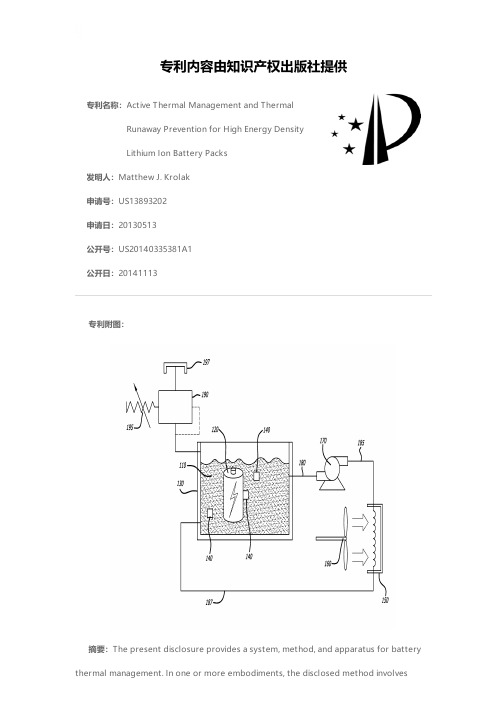
专利名称:Active Thermal Management and ThermalRunaway Prevention for High Energy DensityLithium Ion Battery Packs发明人:Matthew J. Krolak申请号:US13893202申请日:20130513公开号:US20140335381A1公开日:20141113专利内容由知识产权出版社提供专利附图:摘要:The present disclosure provides a system, method, and apparatus for battery thermal management. In one or more embodiments, the disclosed method involvessensing, with at least one temperature sensor, a temperature of at least one battery cell, where at least one battery cell is at least partially submerged within a liquid contained within a battery case. The method further involves comparing the temperature of at least one battery cell with a maximum threshold temperature, and commanding a cooling unit to be activated when at least one processor determines that the temperature of at least one battery cell is above the maximum threshold temperature. Further, the method involves circulating, by at least one pump, the liquid via tubing from the battery case to the cooling unit back to the battery case.申请人:THE BOEING COMPANY地址:Chicago IL US国籍:US更多信息请下载全文后查看。
热盐腐蚀环境对TC11_钛合金高温寿命影响规律试验研究
装备环境工程第20卷第12期·44·EQUIPMENT ENVIRONMENTAL ENGINEERING2023年12月热盐腐蚀环境对TC11钛合金高温寿命影响规律试验研究房宇航,景鑫*,任万聪(西北工业大学 动力与能源学院,西安710072)摘要:目的针对发动机钛合金部件在热盐环境与工作载荷下的寿命衰减问题,开展TC11钛合金热盐腐蚀疲劳与应力腐蚀试验,研究腐蚀环境下TC11的高温寿命衰减规律与失效机理。
方法利用喷盐法制备TC11钛合金试验件,研究不同温度与应力水平对TC11腐蚀疲劳以及应力腐蚀的影响规律。
利用SEM等观测手段,开展腐蚀疲劳以及应力腐蚀试样断口与表面的形貌分析,分析腐蚀环境下的失效机理。
结果热盐腐蚀环境导致TC11的寿命显著降低,对比450 ℃下无腐蚀寿命,腐蚀疲劳寿命下降了2个数量级,应力腐蚀寿命下降到不足1%,且分散性较大。
观察腐蚀疲劳和应力腐蚀的试样可以发现,表面有明显的腐蚀坑,腐蚀坑底发现裂纹。
结论热盐环境下,TC11腐蚀疲劳寿命和应力腐蚀寿命都会明显下降。
由于腐蚀导致钛合金试样表面产生许多腐蚀坑,在腐蚀坑局部形成近似缺口,缺口部位的应力集中是导致腐蚀疲劳寿命衰减的重要因素。
腐蚀疲劳的寿命低于K t=1的无腐蚀疲劳寿命,但是要大于K t=3的无腐蚀疲劳寿命。
关键词:热盐腐蚀;TC11钛合金;腐蚀疲劳;应力腐蚀;失效机理;腐蚀疲劳断口中图分类号:TG172;V252 文献标识码:A 文章编号:1672-9242(2023)12-0044-10DOI:10.7643/ issn.1672-9242.2023.12.006Effect of Hot Salt Corrosion Environment on High TemperatureLife of TC11 Titanium AlloyF ANG Yu-hang, JING Xin*, REN Wan-cong(School of Power and Energy, Northwestern Polytechnical University, Xi'an 710072, China)ABSTRACT: The work aims to conduct hot salt corrosion fatigue and stress corrosion tests of TC11 titanium alloy to investi-gate the high temperature life decay characteristic and failure mechanism of TC11 titanium alloy components in engines under corrosion environment and working load. The TC11 titanium alloy samples was prepared by salt spray method to investigate the effects of different temperature and stress levels on corrosion fatigue and stress corrosion of TC11. The fracture and surface morphology of corrosion fatigue and stress corrosion samples and the failure mechanism were analyzed by SEM and other ob-servation means. Hot salt corrosion environment reduced the life of TC11 titanium alloy, the corrosion fatigue life dropped by two orders of magnitude and the stress corrosion life was less than 1%, compared with the non-corrosion life, and the dispersion收稿日期:2023-10-30;修订日期:2023-12-11Received:2023-10-30;Revised:2023-12-11基金项目:国家科技重大专项(J2019-I-0016-0015)Fund:National Major Science and Technology Project (J2019-I-0016-0015)引文格式:房宇航, 景鑫, 任万聪. 热盐腐蚀环境对TC11钛合金高温寿命影响规律试验研究[J]. 装备环境工程, 2023, 20(12): 44-53. FANG Yu-hang, JING Xin, REN Wan-cong. Effect of Hot Salt Corrosion Environment on High Temperature Life of TC11 Titanium Alloy[J]. Equipment Environmental Engineering, 2023, 20(12): 44-53.第20卷第12期房宇航,等:热盐腐蚀环境对TC11钛合金高温寿命影响规律试验研究·45·was relatively large. By observing the corrosion fatigue and stress corrosion samples, it could be found that there were obvious corrosion pits on the surface and cracks on the bottom of the corrosion pits. The hot salt corrosion fatigue life and hot salt stress corrosion life of TC11 titanium alloy in hot salt environment decrease obviously. Many pits on the surface of titanium alloy samples caused by corrosion form approximatively notches. The stress concentration at the notch is an important factor leading to the decay of corrosion fatigue life. The corrosion fatigue life is lower than the non-corrosion fatigue life of K t=1 but greater than that of K t=3.KEY WORDS: hot salt corrosion; TC11 titanium alloy; corrosion fatigue; stress corrosion; failure mechanism; corrosion fatigue fracture随着我国研究逐步走向深海,飞机与发动机面临的服役环境也越来越复杂。
Application of Thermal Cracking Mechanism of Chrys
J. Chem. Chem. Eng. 7 (2013) 1-5Application of Thermal Cracking Mechanism of Chrysene Molecule Using Density Functional TheoryM.A. Shanshal1 and Q.A.Yousif2*1. Department of Chemistry, College of Science, Baghdad University, Baghdad, Iraq2. Department of Chemistry, College of Science, Al-Qadissya University, Al-Qadissya, IraqReceived: November 19, 2012 / Accepted: December 08, 2012 / Published: January 25, 2013.Abstract: Density functional theory calculations were carried out to study the thermal cracking for chrysene molecule to estimate the bond energies for breaking C10b-C11, C11-H11 and C4a-C12a bonds as well as the activation energies. It was found that for C10b-C11, C11-H11 and C4a-C12a reactions, it is often possible to identify one pathway for bond breakage through the singlet or triplet states. Thus, the C11-H11 and C11-C10b bonds ruptured in triplet state whilst the C12a-C4a in singlet state. Also, it was fond that the activation energy value for C4a-C12a bond breakage is lower than required for C10b-C11 and C11-H11 bonds that enquired the C4a-C12a bond “bridge bond” is a weaker and ruptured firstly in thermal cracking process. It seems that the characteristic planarity for polyaromatic hydrocarbons is an important factor to acquire the molecule structure the required stability along the reaction paths as well as the full octet rule and Clar’s π-sextet structure, especially when chrysene molecular lose the property of planarity. The atomic charges supported the observation that the breaking bonds C10b-C11, C11-H11 and C4a-C12a in triplet or singlet states. The configurations in transition state and the conformation for the end products reaction were explained and discussed.Key words: DFT, chrysene, thermal cracking, C-C rupture, C-H rupture.1. IntroductionThe crude oil or oil residue can be classified according to its saturate, aromatic, resin and asphaltene components [1]. Poly aromatic hydrocarbons are present in high concentrations in crude oil [2]. Thermal cracking or pyrolysis is considered as the dominant reaction mechanism during Kerogen maturation and oil and gas generation in the geological environment [3]. The C-H and C-C bonds rupture reactions are basic for the thermal of aromatic hydrocarbons [4]. The bond dissociation energy “BDE” is essential a probe for the reaction enthalpy of the homolytic cleavage of the considered bond. The BDE is a good indicator of chemical reactivity since it represents a reliable measure of bond strength [5]. The bulk of the experimental of the physical properties to polyaromatic*Corresponding authors: Qhatan A. Yousif, Processor, research fields: quantum and physical chemistry. E-mail: *********************.aromatic hydrocarbon “PAHs” have been to identify the vibrational frequencies [6]. It is much more difficult to determine experimentally the C-H and C-C BDEs of these large species compared to monocyclic compounds and thus experimental C-H and C-C BDEs of the “PAHs” are very scarce in the literature. Therefore, a lot of researchers have focused on the accurate theoretical calculation of BDEs [4-6]. The aim of this work is to use computational methods to study the C12a-C4a, C11-C10b and C11-H11 BDEs of chrysene molecule one of the polyaromatic hydrocarbons via the hybrid DFT B3LYP method.2. Computational MethodAll DFT calculations were performed using the Gaussian09 program [7] running on the workstation that have the high performance in a CPU and memory size. The B3LYP function in conjugation with the6-311G [8, 9] basis set was used to optimizationl Rights Reserved.Application of Thermal Cracking Mechanism of Chrysene Molecule Using Density Functional Theory2geometries. This level of theory is known to provide a quantitatively good description of geometries which has, in particular, been shown for radical study at the PAHs [5]. All DFT involving computations the open-shell radical species were performed using the unrestricted methodology [9].3. Results and DiscussionThe energies required to break C12a-C4a, C11-C10b, C2-H2 and C1-H1 bonds have been calculated by virtue of the singlet and triplet state. By examining the potential energy curves one can deduce whether a particular reaction pathway for bond breakage is favoured in comparison with other pathways. However, for the C11-C10b, C2-H2 and C1-H1 bonds reactions, it is possible to identify one pathway for bond breakage through the triplet state and C12a-C4a bond reaction at singlet by employing the density functional theory. The carbon and hydrogen atoms of the chrysene moleculeare numbered in conformity with the convention laiddown by the International Union of Pure and AppliedChemistry “IUPAC” for regular naming of chemical compounds. The values for the activation energy (136.968 kcal/mol) at bond length 2.8Å and the reaction energy (114.5480 kcal/mol) at the bond length 2.9Å via a singlet state pathway are exhibited in Fig. 1. Scheme. 1 can be invoked to discuss the reactionmechanism that includes the cleavage of the C12a-C4aFig. 1 Potential energy curve for chrysene molecule for C12a-C4a bond breakage.bond via a transition state structure, including the atomic charges for all atoms in the molecule. Firstly in the transition state, the closed chain of the hydrocarbon is configured that contains resonance and double bonds. The allene fragment (the atom C12a is central to the allene) is constituted and shared by the resonance process with other carbon atoms. So, all the atoms conform to a stable octet number rule [10, 11] without loss of planarity. In the singlet state (bond length 2.9 Å) the closed distorted chain of the hydrocarbon is formed that contains single and double bonds. The allene fragments is constituted and unshared with carbon atoms through the resonance process. Thus, all the atoms reach a stable electronic octet [10, 11].Likewise, Fig. 2 shows the atomic charges for C12a and C4a which confirms that the C12a-C4a breaks beyond a bond length of 2.8Å.The activation energy value (158.4086 kcal/mol) at the bond length 3.4Å and the reaction energy value (131.1401 kcal/mol) at the bond length 3.5Å following the singlet state pathway are shown in Fig. 3.The mechanism of the reaction that includes a transition state structure and the breaking of the C10b-C11 bond are described by means of Scheme 2. In the transition state, the benzene ring is opened between the carbon atoms (C10b and C11). The occurrence of rotation around the C4a-C4b bond axis with loss of planarity as a result leads to the strong interactions between the following atoms (the carbon atom C10b with C6, the hydrogen atoms H1 with H12; H4 with H5 and H11 with H10). In the triplet state, the occurrence of greater rotation around the C4a-C4bScheme. 1 Transition state, the product of the cleavage of the C12a-C4a bond, and the atomic charges for each the atoms (distinguished by means of colour).ΔE (k c a l /m o l )Bond length (Å) A c t i v a t i o n R e a c t i o n e n e r g y a tl Rights Reserved.Application of Thermal Cracking Mechanism of Chrysene Molecule Using Density Functional Theory3Fig. 2 Atomic charges for C12a and C4a for chrysene molecule.Fig. 3 Potential energy curve for chrysene molecule for C11-C10b bond breakage.Scheme. 2 Transition state, the product of the cleavage of the C10b-C11 bond, and the atomic charges for each the atoms (distinguished by means of colour).bond axis with loss of planarity, leading to a reduction in the aforementioned strong interaction. Consequently, this modification gives the required stability for themolecule structure owing to a reduction in the overlap of the orbitals between the ethylene and naphthalene fragments. At the same time, this enhances the overlap of the orbitals for the naphthalene part and accomplishes a greater distribution of electron density on both sides of the molecule (see the electrostatic potential map “ESP”).Thus, Fig. 5 confirms the cleavage of the C10b-C11 bond at a bond length of 3.5 Å.The activation energy value (154.9645 kcal/mol) at the bond length 4Å and the reaction energy value (115.1715 kcal/mol) at the bond length 4.1Å following the triplet state pathway are shown in Fig. 6. The mechanism of the reaction that includes a transition state structure and the breaking of the C11-H11 bond is described by means of Scheme. 3.Fig. 4 ESP for chrysene molecule for C11-C10b bond breakage.Fig. 5 Atomic charges for C10b and C11 for chrysene molecule.Bond length (Å) Atomic charge C12a at singlet stateA t o m i c c h a r g e sAtomic charge C4a at singlet stateΔE (k c a l /m o l )Bond length (Å)A c t i v a t i o n e n e r g y R e a c t i o n e n e r g y a t t r i p l e t s t a t eAtomic charge C11 at singlet stateAtomic charge C10b at singlet stateA t o m i c c h a r g e sBond length (Å) l Rights Reserved.Application of Thermal Cracking Mechanism of Chrysene Molecule Using Density Functional Theory4In both states, the hydrogen atom (H11) is moved away from the molecule with retention by the same plane in the sense that the interaction is experienced equally by the hydrogen atoms (H11) and (H10, H12). Thus, at a bond length of 4.1Å in triplet state the hydrogen atom H11 is moved away from the molecule as a free radical and moved far from the planar molecule. Thus, the two (Clar’s π-sextet structure) have been configured and both structures preserve the planarity characteristic of aromatic compounds. The conversion of atomic charges for carbon atom C11 and hydrogen atom H11 from positive values into negative values and to a value that is close to zero that suggeststhat the release of the hydrogen atom H11 as a freeradical occurs without any interactions with otheratoms (this is shown in Fig. 7. Moreover, Fig.7 provides evidence for the cleavage of the C11-H11bond at the aforementioned length.Fig. 6 Potential energy curve for chrysene molecule for C11-H11 bond breakage.Scheme. 3 Transition state, the product of the cleavage of the C11-H11 bond, and the atomic charges for each the atoms (distinguished by means of colour).Fig. 7 Atomic charges for C10b and C11 for chrysenemolecule.4. Conclusions The activation energies values is arranged in thefollowing sequence C10b-C11 > C11-H11 >C4a-C12a. The low activation energy value for C4a-C12a bond due to the transition state is full octet. Thus, the low activation energy value C11-H11 bondowing to the transition state is completely planar and have the good variation atomic charges via a bond length and the C11 carbon atom is retained of a positive charge values as a proceed reaction. There are different mechanisms to describe the cleavage C12a-C4a, C11-C4a bond as results to different end products. As C4a-C12a bond in chrysene molecule is weaker than C11-H11 and C10b-C11 bonds, it is reasonable to presume that C4a-C12a bond is broken first when chrysene molecule is exposed to thermal cracking.References[1] Castellano, O.; Gilman, R. Therotical Study of Interactionin Hetroatomic Moncyclic Molecular Complexes of Benzene, Pyridine and Thiophene Dimmers. Energy Fuels 2011, 25, 2526-2541.[2] Olah, G. A. Hydrocarbon Chemistry; John, Wiely & Sons:New York, 2003.[3] Meng, X.; Xu, C. Catalytic and Thermal Pyrolysis ofAtmospheric Residue. Energy & Fuels 2003, 23, 65-69.ΔE (k c a l /m o l )Bond length (Å)A c t i v a t i o n e n e r g yR e a c t i o n e n e r g y a t t r i p l e t s t a t e Atomic charge H11 at triplet state Atomic charge C11 at triplet state A t o m i c c h a r g e sBond length (Å) l Rights Reserved.Application of Thermal Cracking Mechanism of Chrysene Molecule Using Density Functional Theory 5[4]Shanshal, M.; Muala, M. M. Reaction Paths andTransition States of C-H Bond Rupture in Aromatics, Benzene and Toluene. Jordan Journal of Chemistry2011,6, 165-173.[5]Hemloset, K.; Van, V. Specybroeck Bond DissociationEnthalpies of Large Aromatic Carbon-Carbon Radical. J.Phys .Chem. A2008,122, 13566-13573.[6]Barkholt, C.; Hadad, C. M. C-H and N-H BondDissociation Energy of Small Aromatic Hydrocarbons. J.Am. Chem. Soc.1999,121, 491-504.[7]Frisch, M. J.; Trucks, G. W.; Schlegel, H. B.; Scuseria, G.E.; Robb, M. A.; Cheeseman, J. R.; et al. I nformation &Communications; the National Academy of Science: USA, 2009.[8]Sholl, D. S.; Steckel, J. A. Density Functional Theory;John Wiely: New York, 2009.[9]Bachrach, S. M. Computational Organic Chemistry; JohnWiely: New York, 2007.[10]Smith, M. B.; March, J. March’s Advanced OrganicChemistry; Jonh Wiely: New York, 2007.[11]Smith, J. G. Organic Chemistry; McGraw & Hill Press:New York, 2011.l Rights Reserved.。
EN71-3-2013-元素的迁移
EN71-3 2013 Safety of toys - Part 3: Migration of certain elements玩具安全-第3部分:元素的迁移1 Scope(范围)This European Standard specifies requirements and test methods for the migration of aluminium, antimony, arsenic, barium, boron, cadmium, chromium (III), chromium (VI), cobalt, copper, lead, manganese, mercury, nickel, selenium, strontium, tin, organic tin compounds and zinc from toy materials and from parts of toys.本欧洲标准规定了下列从玩具材料和玩具部件中转移的元素的详细要求和测试方法:铝、锑、砷、钡、硼、镉、铬(3+)、铬(6+)、钴、铜、铅、锰、汞、镍、硒、锶、锡、有机锡和锌。
Packaging materials are not considered to be part of the toy unless they have intended play value.包装材料不包括在本标准范围之类,除非它们属于玩具部分或者有娱乐价值。
The standard contains requirements for the migration of certain elements from the following categories of toy materials:Category I : Dry, brittle, powder like or pliable materials;Category II : Liquid or sticky materials;Category III : Scraped-off materials.下列玩具种类的元素转移包括在本标准的要求之内:第一类:干燥,易碎,粉末状或柔软的玩具材料;第二类:液体状/粘稠性玩具材料;第三类:玩具表面刮出物。
F.装甲钢马氏体相变塑性的实验研究
第15卷第1期2008年2月塑性工程学报J OU RNAL OF PL ASTICIT Y EN GIN EERIN GVol 115 No 11Feb 1 2008装甲钢马氏体相变塑性的实验研究3(清华大学机械工程系先进成形制造教育部重点实验室,北京100084) 孙朝阳方 刚雷丽萍 曾 攀摘 要:采用G leeble 热模拟实验机对装甲钢马氏体相变塑性进行了研究。
通过对热变形中的热应变、组织应变和弹性应变进行分离,从总应变中分离了相变塑性,并得到了相变塑性的定量关系式,采用Greenwood 2Johnson 模型得到该种材料的相变塑性系数。
分析结果表明,该种材料的相变塑性、组织应变和热应变是引起变形的主要原因,相变塑性与组织应变数值相当,在热处理变形分析中不容忽视;随着温度降低及马氏体体积分数增大,相变塑性迅速增大,马氏体体积分数达到018后,相变塑性基本保持不变;随着施加应力的增加,相变塑性逐渐增大,相变塑性与施加应力呈线性关系。
文章研究结果不仅为该种材料热处理、焊接过程形状畸变和残余应力研究提供基础,还为该材料复杂热力学行为研究提供参考。
关键词:相变塑性;马氏体相变;装甲钢中图分类号:T G 113125+3 文献标识码:A 文章编号:100722012(2008)0120070206Experimental study of m artensitic transform ationplasticity for armour steelSUN Chao 2yang FAN G Gang L EI Li 2ping ZEN G Pan(Key Laboratory for Advanced Manufacturing by Materials Processing Technology ,Departmentof Mechanical Engineering ,Tsinghua University ,Beijing 100084 China )Abstract :The quenching experiments for cylinder specimens of the armour steel under uniaxial loading were performed ,where the martensite transformation and transformation plasticity occurred.During the thermo 2mechanical processing ,the specimen πs radial strain includes elastic strain ,thermal strain ,transformation strain and transformation plascticity ,and the transformation plasticity was separated f rom the total radial strain.Based on the Greenwood 2Johnson model ,the parameter of transformation plasticity was evaluated.The results show that transformation plasticity has equivalence effects on the deformation of quenching specimen.Transformation plasticity increases with the decreasing temperature and the increasing of martensitic volume f raction and uniaxial loading.The research contributes to understanding complex thermal 2mechaical behavior of armour steel and predic 2tion of the deformation of thermal treatment.K ey w ords :transformation plasticity ;martensitic transformation ;armour steel3国家自然科学基金资助项目(50575124)。
- 1、下载文档前请自行甄别文档内容的完整性,平台不提供额外的编辑、内容补充、找答案等附加服务。
- 2、"仅部分预览"的文档,不可在线预览部分如存在完整性等问题,可反馈申请退款(可完整预览的文档不适用该条件!)。
- 3、如文档侵犯您的权益,请联系客服反馈,我们会尽快为您处理(人工客服工作时间:9:00-18:30)。
Confidential
11
Pouch cell pack has different thermal behavior
Trigger Cell
PCM Critical Specifications PCM Cell -Thermal conductive : replace cooling plates -High latent heat: heat sink - Vescoelastic: replace foam separators Option: Remove heat to external PCM heat sink using heat pipes
15
Compact | Lightweight | Long Lasting
Confidential
When is liquid cooling used?
High Air cooling
Without PCM
Liquid cooling
Air cooling
C-rate
Energy Density
“The different chemistries have different thermal characteristics and so we’ve been able to incorporate how to make sure from a thermal perspective that we’ve got it...” Denise Gray, Advanced Battery Director of GM
“Thermal management of lithium-ion battery systems is critical to the success of all-electric vehicles because extreme temperatures can affect performance, reliability, safety and durability.” – V. Anand Sankaran, Executive technical leader, Ford Energy Storage & High Voltage Electrical Systems
4
Thermal Runaway Containment
Compact | Lightweight | Long Lasting
Confidential
System thermal management is the last line of defense
Cell chemistry, packaging, and manufacturing advancements will continue to improve safety Additional safety mechanisms will always be necessary Phase change material (PCM) combined with thermal conductors (copper, graphite foil) offers simple, effective, multi-use solution
Compact | Lightweight | Long Lasting
Confidential
3
How PCM-graphite works
Wax Absorbs Heat As It Melts Graphite Distributes Heat Evenly
Temperature With No PCM Temperature with PCM
Compact | Lightweight | Long Lasting
Confidential
Lithium-ion chemistry has large power/energy range
HEV
PHEV EV
Cycle life and cost per kWh generally increase with specific power
Thermal runaway triggered for Cell #2
PCM 1 PCM 2 PCM 3
Cell1 Cell2 Cell3 Cell4
PCM 4 PCM 5
• Peak temperature on face of cell 1: ~ 80C • Peak temperature on face of cell 3: ~ 80C • Kept neighboring cells to below 90C, per SAE J2929 safety standards
Confidential
PCM slabs between cells require thermal linkage PCM
Compact | Lightweight | Long Lasting
PCM
Cell
12
AllCell PCM can prevent thermal runaway propagation with pouch cells
Thermal Runaway Containment and Thermal Management Using Phase Change Material (PCM)
The NAATBatt Workshop on Li-ion Thermal Safety
Austin, TX January 16-18, 2013
ห้องสมุดไป่ตู้
Size
Large Format – high amount of energy Small format
Compact | Lightweight | Long Lasting
Confidential
7
Safety improvements are being made on multiple fronts
With PCM Heat Removal Intensity
Low
HEV (Prius)
PHEV (Volt)
Compact | Lightweight | Long Lasting
EV (Leaf)
Confidential
Ceramic Materials
Compact | Lightweight | Long Lasting
8
If heat removal is insufficient…
Compact | Lightweight | Long Lasting
Confidential
9
AllCell PCM can prevent thermal runaway propagation with cylindrical cells
Melting Point Temperature Remains Constant During Melting
Time
Lightweight Thermally conductive Design flexibility Viscoelastic
Confidential
Compact | Lightweight | Long Lasting
R. Kizilel ,R. Sabbah, J. R. Selman, S. Al-Hallaj, ”An Alternative Cooling System to Enhance the Safety of Li-ion Battery Packs”, Journal of Power Sources, 194, (2009), 1105-1112
L_exp 150
100
Trigger cell
50
0 0 50 100 Time (s) 150 200 250
R. Kizilel ,R. Sabbah, J. R. Selman, S. Al-Hallaj, ”An Alternative Cooling System to Enhance the Safety of Li-ion Battery Packs”, Journal of Power Sources, 194, (2009), 1105-1112
Compact | Lightweight | Long Lasting
Confidential
6
System must handle worst case heat release
Trigger mechanism
Internal short – short time frame External short Overcharge
Phase Change Material
Electrode Coatings
Shutdown Separators
Safety Vents
Safety Circuits
Positive Thermal Coefficient Devices Conductive Polymer
Confidential
Compact | Lightweight | Long Lasting
Confidential
Presentation Outline
• Li-ion battery characteristics • What is PCM? • Thermal Runaway Containment • Cylindrical Cells • Pouch Cells • Thermal Management • Cylindrical Cells • Pouch Cells • Concluding Remarks