Webrc Configuration management for a cooperation tool
Oracle Enterprise Manager 13c Cloud Control 产品说明书

Oracle Enterprise Manager 13c Cloud ControlOracle SOA Management Pack Enterprise EditionMANAGEMENT FOR ORACLE SOA SUITE AND ORACLE SERVICE BUS APPLICATIONS Oracle Enterprise Manager is Oracle’s integrated enterprise IT management product line, and provides the industry’s first complete cloud lifecycle management solution. Oracle Enterprise Manager’s Business-Driven IT Management capabilities allow you to quickly set up, manage and support enterprise clouds and traditional Oracle IT environments from applications to disk. Enterprise Manager allows customers to achieve best service levels for traditional and cloud applications through management from a business perspective including for Oracle Fusion Applications, provide maximum return on IT management investment through the best solutions for intelligent management of the Oracle stack and engineered systems and gain unmatched customer support experience through real-time integration of Oracle’s knowledgebase with each customer environment.F E A T U R E S∙Track and monitor end-to-end business transactions across tiers∙Monitor the performance of Oracle SOA Suite and Service Bus∙Integrated web service testing and synthetic transaction monitoring∙Integrated authoring, attachment, and monitoring of security policies∙Collection and analysis of SOA configuration information∙Automated provisioning of Oracle SOA Suite and Service Bus∙Seamless Lift and Shift of SOA Domains and composites to Oracle Cloud. Fusion Middleware ManagementOracle Enterprise Manager’s Fusion Middleware Management solutions provide full-lifecycle management for Oracle WebLogic, SOA suite, Coherence, Identity Management, WebCenter, and Oracle Business Intelligence Enterprise Edition. Oracle Enterprise Manager provides a single console to manage these assets from a business and service perspective, including user experience management, change and configuration management, patching, provisioning, testing, performance management, business transaction management and automatic tuning for these diverse environments.SOA ManagementUnderstanding complex service dependencies, monitoring consumer expectations, and controlling service ownership costs are the biggest barriers to effectively managing service-oriented architecture (SOA) applications and infrastructure. To overcome these challenges, administrators need solutions that increase service visibility and production assurance while lowering the cost and complexity of managing SOA environments. Oracle SOA Management Pack Enterprise Edition provides runtime governance as well as comprehensive service and infrastructure management functionality to help organizations maximize the return on investment from their SOA initiatives.Automate SOA Service and Transaction managementOracle SOA Management Pack Enterprise Edition provides administrators with a consolidated browser-based view of the entire SOA environment, enabling them to monitor and manage all their components from a central location. This streamlines the correlation of availability and performance problems for all components across the SOA environment. Oracle Enterprise Manager integrates with the Oracle Fusion MiddlewareControl, Oracle Service Bus console, and Oracle Business Activity Monitoring. With aKEY BENEFITS∙Provides visibility into complex SOA orchestrations across the enterprise ∙Minimizes the cost of setting up and maintaining performance monitoring ∙Reduces the effort associated with manual application deployment∙Dramatically improves the ability to keep up with environmental changes ∙Significantly lowers the total cost of ownership for SOA∙Significantly reduces time required to move SOA and OSB assets to Oracle Cloud.∙Single Pane of Glass to monitor and manage assets across clouds. rich set of service and system-level dashboards, administrators can view service levels for key web services, SOA composites, Oracle Service Bus proxy and business services, as well as SOA infrastructure components.Figure 1. Service Bus and SOA Composites Heat MapOracle Enterprise Manager allows you to manage your Oracle SOA Suite applications leveraging a model-driven “top-down” approach within your development, quality assurance (QA), staging, and production environments. Business application owners and operational staff can automatically discover and correlate your SOA composites, components, services, and back-end Java EE implementations through detailed modeling and drill-down directly into the performance metrics at the component level. Business transactions and service dependencies can be automatically discovered and the message flows mapped. Details about individual and aggregate transaction execution can be searched for and displayed.By providing and maintaining the business context while traversing your organization’s application infrastructure, your developers and operational staff can leverage Oracle Enterprise Manager to meet the high availability and top performance criteria necessary to maximize business results.Figure 2. SOA composite instance search and traceOracle Enterprise Manager enables your application development and support teams to: ∙Continuously discover components, transaction flow, service dependenciesand relationships∙Monitor business transactions as they flow across tiers∙Manage Oracle SOA Suite applications with minimal manual effort, regardless of application-specific knowledge or programming expertise∙View aggregated dependences or drill-down to method-level interactions∙Monitor endpoint performance with both synthetic service tests and deep component implementation visibility∙Search and analyze single instance transaction performance, with built-in report generation for slowest running or faulted instances∙Link to related diagnostic and database metrics, taking advantage of SOA Suite specific knowledge∙Quickly isolate and diagnose the root cause of SOA application performance problems in QA, staging, and production environmentsFigure 3. SOA composite instance search and trace∙Quickly view the SOA dehydration database performance by viewing the dehydration store growth rate, table space, wait bottlenecks, top SOA SQLsand a lot more.Configuration ManagementConfiguration information for the Oracle SOA Suite, Oracle Service Bus, and BPEL processes are collected and stored in the Oracle Enterprise Manager repository. With this information, administrators can:∙View the historic configuration changes across the SOA Suite and Oracle Service Bus environment∙Baseline a working configuration by saving it in the repository∙Compare SOA Suite and Oracle Service Bus server and domain configuration parameters with other servers and domainsLifecycle ManagementOracle SOA Management Pack Enterprise Edition allows administrators to automate SOA Suite patching, deployment, and server provisioning, as well as Service Bus deployment and server provisioning.SOA administrators can automate patching of SOA infrastructure spread across multiple machines in parallel. Patch plans can be created that will comprise of multiple patches, while patch conflicts can be proactively detected by running patch plan analysis before actually applying the patch plan to the entire SOA Infrastructure setup. Rollbacks can be automated similar to patching automation.Administrators can deploy multiple SOA composites and Service Bus projects to servers using the deployment procedure framework. A multistep interview process lets users choose the source files for the process, project or resource, target domain, and credentials, then schedule a future deployment using the job system. This enables administrators to:∙Clone directly from test to production∙Clone from fully tested gold image stored in software library∙Provision new composite or new version of existing composite to existing SOA Infrastructure∙Specify composite from software library or file system∙Optionally specify configuration planAdministrators can provision new Service Bus and SOA Suite domains based on Middleware Provisioning Profiles in Software Library. The provisioning process allows for configuration parameters to be set on the domains being provisioned.Historical Analysis and ReportingIn addition to real-time monitoring of metrics for SOA infrastructure targets, Oracle Enterprise Manager stores the collected metric and configuration data in a central repository enabling administrators to analyze metrics through various historical views (such as Last 24 Hours, Last 7 Days, and Last 31 Days) to facilitate strategic trend analysis and reporting. Customizable service and system dashboard functionality allow users to create reports on various services and systems for service level availability, usage, performance, and business indicators.O R A C L E D A T A S H E E TFigure 4. SOA Composite export, SOA Diagnostics and IWS Report Snapshots.Now users also have option to generate and view IWS [Integration Workload Statistics] reports from within Enterprise Manager. IWS reports list transaction data for all composites with many more details.The Ideal ChoiceSOA delivers agility to an enterprise; however, if not properly managed, may increase management complexity and cost. Oracle Enterprise Manager makes it easy for IT administrators to effectively manage SOA complexity by providing runtime governance in conjunction with business and IT alignment. Offering service level management, triage, and root cause analysis at all SOA application levels, Oracle Enterprise Manager is an ideal choice for maximizing consistent SOA application performance and creating a superior ownership experience.O R A C L E D A T A S H E E TC O N T A C T U SFor more information about SOA Management Pack, visit or call +1.800.ORACLE1 to speakto an Oracle representative.C O N N E C T W I T H U S/oracle /oracle /oracle Copyright © 2016, Oracle and/or its affiliates. All rights reserved. This document is provided for information purposes only, and the contents hereof are subject to change without notice. This document is not warranted to be error-free, nor subject to any other warranties or conditions, whether expressed orally or implied in law, including implied warranties and conditions of merchantability or fitness for a particular purpose. We specifically disclaim any liability with respect to this document, and no contractual obligations are formed either directly or indirectly by this document. This document may not be reproduced or transmitted in any form or by any means, electronic or mechanical, for any purpose, without our prior written permission.Oracle and Java are registered trademarks of Oracle and/or its affiliates. Other names may be trademarks of their respective owners. Intel and Intel Xeon are trademarks or registered trademarks of Intel Corporation. All SPARC trademarks are used under license and。
CUSTOMER RELEASE NOTES

CUSTOMER RELEASE NOTESFTTH witch ES3526SFirmware Version 1.0.3.8INTRODUCTION:The ES3526S is a cost effective managed FTTH(Fiber to the home) Layer 2 Switch. Each ES3526S unit contains 24 fiber ports with two expansion slots. The slots can support expansion modules such as 1000Base-T,1000Base-SX, 1000Base-LX and 100FX modules.The base hardware is a 1U height, 19” rack mountable metal enclosure. The switch can be managed either by in-band management via the network station remotely or out-of-band management via the console port (RS232) locally. An imbedded Web agent also provides management capability to any computer on the network via common Http browsers such as Netscape Navigator (shall be Version 6.2 or above) or Microsoft’s Internet Explorer (should be Version 5.0 or above).Local Console Management (LCM) allows the user to monitor and configure the ES3526S from a VT-type terminal. LCM can be used to configure features such as SNMP community names and access rights, Port Enable/Disable, firmware downloads, and Device IP address as well as most other parameters. LCM can also provide statistical and diagnostic information about the entire device or an individual port.Management of the switch is password protected; the same password is used for LCM and for the Web browser interface. Prior to accessing the Management Module via a network connection, a valid IP address, subnet mask, and in some cases a default gateway must be configured using an out of band connection or the BootP/DHCP protocol. The management option provides SNMP, RMON (4 groups: 1,2,3,9), and Web management for system control and statistical monitoring.It is recommended that one thoroughly review this release note prior to the installation or upgrade ofthis product.FIRMWARE SPECIFICATION:Status Version No. Type Release Date Customer release 1.0.3.8 Customer 10/17/2007Customer release 1.0.3.7 Customer 08/20/2007Customer release 1.0.3.6 Customer 08/15/2007Customer release 1.0.3.4 Customer 04/03/2007Customer release 1.0.3.3 Customer 11/23/2006Customer release 1.0.3.2 Customer 04/30/2006Customer release 1.0.3.1 Customer 03/01/2006Customer release 1.0.3.0 Customer 12/27/2005Customer release 1.0.2.8 Customer 12/23/2005Customer release 1.0.2.7 Customer 10/20/2005HARDWARE COMPATIBILITY:ALLBOOTPROM COMPATIBILITY:6/2000 P/N: 9038023-04 Subject to Change Without Notice Page: 1 of 14CUSTOMER RELEASE NOTES6/2000 P/N: 9038023-04 Subject to Change Without Notice Page: 2 of 14fix the following bugsRuntime Diag LoaderES3526S-38 v1.0.2.9 and former version .OASW_Diag_V0.0.5.1.bix OASW_Loader_V1.7.0.2.BIN and former versionNETWORK MANAGEMENT SOFTWARE SUPPORT:NMS Platform Version No.Module No. TBDIf you install this image, you may not have control of all of the latest features of this product until the next version(s) of network management software. Please review the software release notes for your specific network management platform for details.SUPPORTED FUNCTIONALITY:Category Feature Support PriorityMonitor EnvironmentPower Status Yes RTS Switching Features VLAN 802.1Q – Tag-based Yes RTS 802.1Q – Port-based Yes RTS 802.1Q – Remove Tag Yes RTS 127+ VLANs per switch Yes RTS GVRP Yes RTS PVLAN Yes RTS Priority/ CoS L2: 802.1p – Tag-based Yes RTS L2: 802.1p - Queuing 4 queues per port RTS Link Aggregation Cisco EtherChannel Yes RTS Port Mirroring Port Mirroring Yes RTS Broadcast Storm Control Broadcast Storm Control Yes RTS Spanning Tree 802.1w Yes RTS Fast Link Option Yes RTS Port-Security Port-Security Yes RTS IEEE802.1xPort-Security IEEE802.1x Yes RTS Bandwidth Management Rate Limiting Yes RTSSystem SoftwareIP Address Management Static Yes RTS BootP Yes RTS DHCP client Yes RTS Configuration Management Configuration File Yes RTS Firmware upgrade Yes RTS Access Control Various privileges Yes RTS Remote authentication & authorization – RADIUS Yes RTSWeb Management Switch Front Panel View Yes RTS Look & Feel Yes RTS Character-Based Management Cisco-like CLI via Telnet and Serial PortYes RTSSNMP Management SNMP v2c Yes RTS MIB support Yes RTS Private MIB Yes RTSCUSTOMER RELEASE NOTES6/2000 P/N: 9038023-04 Subject to Change Without Notice Page: 3 of 14Category Feature Support Priority Alerts Yes RTS SNTP client Yes RTS ACL Yes RTSINSTALLATION AND CONFIGURATION NOTES:In general, the ES3526S Switch will be shipped to you pre-configured with this version of firmware. If you would like to upgrade an existing ES3526S Switch, please follow the TFTP download instructions that are included with your firmware image upgrade kit.FIRMWARE CHANGES AND ENHANCEMENTS:ES3526S-38 v1.0.3.8 fix the following bugs1. Modified the character of port security learnt MAC address.As customer MRV request , the mac address should be not aged out when enable port security in OA2000(MRV project).Now port security working as this way:If the system finds a new MAC address learnt, it will write the MAC address back to the MAC chip, only change the aging( dynamic) bits to static.An issue exist, and it can not be resolved in SW Mercury1.0 platform and the too old Broadcom chip: Send packets of some MAC address A, with speed large than 1750p/s by SmartBits, when the system writes aging bits of this MAC address A into the Broadcom MAC chip, it can not be well done. This issue is not caused by port security, but will influence it.ES3526S-38 v1.0.3.7 fix the following bugs1. Customer finds wrong description in IGMP Snooping function. Wrong function description about IGMP Snooping Correct:Console(config)#ip igmp snooping ?querier Enable IGMP snooping acting as querier query-count Configure the query count query-interval Configure query interval query-max-response-time Configure the report delayrouter-port-expire-time Configure router port expire time version IGMP snooping versionvlan Configure static router port or member portWrong:Console(config)#ip ig snooping ?immediate-leave Enable IGMP snooping immediate-leaveEnable IGMP snooping acting as querier querier Configure the query count query-count Configure query interval query-interval Configure the report delayquery-max-response-time Configure router port expire time router-port-expire-time IGMP snooping versionversion Configure static router port or member port vlan Configure lacp statusCUSTOMER RELEASE NOTES6/2000 P/N: 9038023-04 Subject to Change Without Notice Page: 4 of 14ES3526S-38 v1.0.3.6 fix the following bugs 1. Resolved ES3526S-38FM-00003=====Root Cause=====1. When the querier send general query, the non-querier only send one report of respective groups to the querier when it receives IGMP reports durning maximum response time. If thehost send leave packet at this moment when the non-querier has send one report to the querier but still during MRT, the non-querier do not forward other member's report to the querier when the querier send GS-query downstream. It will make the group removed on the querier.2. It is due to that non-querier does not reset "queryTimeStamp", "duringMAXinterval" when it receives the GS-query after receiving general-query. =====Resolution=====When the non-querier receive GS-query after receiving general-query, set "queryTimeStamp" to 0 and "duringMAXinterval" to FALSE to invalidate the effect of the former general query. =====Modified file=====Src\Core\L2\l2mcast\igmpsnp\igmpsnp.c2. yunlong.zhan: Resolved issue from customer. Customer've got a trouble with IPTV broadcasting:In D-link segment when Customer closes the VLC Player, the streaming to port where Customer placed stop.In Accton segment when Customer closes the VLC Player, the streaming to port where Customer placed goes one. So a lot of useless traffic on port (flood) Both switches have the same configuration " Static Multicast routing" function.This issue caused by packet flooding issue in non multicast port. Modified files: igmpSnp.c, igmpSnpDynIp.c, sys_component.hES3526S-38 v1.0.3.4 fix the following bugs1. Resolved the system busy issue when the BPDU storm issue on downlink port. (1) 在端口状态为down时,拔线,30秒后端口状态不会变为up (2)用hub产生的环路,也能正确把端口down掉,恢复也正常。
CAXOsoftwansync

CA Recovery ManagementSolutionCA ARCserve® BackupCA XOsoft™ WANSync™HACopyright © 2007 CA. All rights reserved. All trademarks, trade names, service marks and logos referenced herein belong to their respective companies.PRODUCT FAMILY BRIEF: CA XOSOFT WANSYNC3The CA XOsoft WANSync Product Suite: Business ContinuityOver the WANT oday, almost every enterprise, regardless of size or type, does business electronically via somecombination of IT-enabled tools. This means that almost every business is entirely dependantupon reliable, continuous access to the applications and information that enable the businessto do business.At the same time, threats to corporate IT resources grow in number, type and severity almostdaily. Threats include viruses and “malware”, accidental and intentional data corruption, theftor loss of mobile computers hosting critical information and, natural and man-made disasters.Other challenges include the need to consolidate, migrate or virtualize servers and theresources they host without disrupting operations or putting those resources in jeopardy.Amplifying all of this is the need to do business “at web speed.” This means not only protectingthe business against disruption of operations and revenues from loss of access to IT resources.It also means restoring those resources to a current, usable state as rapidly as possible.The CA XOsoft WANSync Product Suite provides a single, integrated, high-performanceresponse to all of these challenges. The solution provides comprehensive replication ofapplications, databases and files, and near instantaneous failover and restoration of theseresources after any loss or disruption. Integrated, automated testing of disaster recoveryresources is also supported through CA XOsoft’s unique Assured Recovery™ option, to helpensure readiness in the face of actual threats. This combination of real-time replication,application monitoring, application failover/failback and CA Assured Recovery keeps criticalIT-enabled business resources available and reliable, helping to keep users working andproductive, impervious to the broadest array of threats from the most severe to theday-to-day issues that may arise.The CA XOsoft WANSync Product Suite integrates several general-purpose synchronizationand real-time replication solutions. These solutions come in several flavors unlocked by yourspecific license key:•CA XOsoft™ WANSync™ for Disaster Recovery (DR)provides real-time data replicationand rewind (CDP) for data availability, even across platforms covering Windows, UNIX andLinux to reduce recovery time objectives (RTO).•CA XOsoft™ WANSync™ CD for Content Distribution, Delivery & Web Publishing on alarge scale to serve needs ranging from global web content distribution to large scalecentralized backup.•CA XOsoft™ WANSync™ HA for simplified DR by incorporating automated High Availabilityis the flagship CA XOsoft WANSync Product Suite product addressing not only recoverypoint objective (RPO) needs but also RTO by incorporating application aware, monitoring,failover/failback, stand-by application/data testing via Assured Recovery and integrationwith VSS snapshots and backup solutions, including full GUI level CA ARCserve® Backupintegration.4PRODUCT FAMILY BRIEF: CA XOSOFT WANSYNC•CA XOsoft™ WANSync™ HA Server provides increased protection for file and application servers of any type. The solution monitors the health of connected applications, and notifies the appropriate IT administrator when something is wrong. This can either trigger an automatic failover or allow the administrator to perform “push-button”, single-click server failover or failback. The software also moves shares appropriately and helps ensure that users maintain access to authorized resources without any client-side change.In addition, a set of dedicated solutions provide specific resources with complete availability assurance.•CA XOsoft™ WANSync™ HA, High Availability Solution Suite For Exchange is the definitive WAN-based integrity and availability platform for Microsoft Exchange. It automatically maps and retrieves all Exchange database components (including the message database, storage group and associated data, and transaction log files). This enables streamlined set-up and seamless, comprehensive high availability. CA XOsoft WANSync HA Exchange secures entire stand-alone or clustered Exchange servers, constantly replicates changes to either local or remote replicas in real time. Should Exchange servers fail for any reason, geographically remote replicas are available to take their place, quickly providing the fastest path to recovery.•CA XOsoft™ WANSync™ HA, High Availability Solution Suite For SQL is the most comprehensive WAN-based disaster recovery platform for Microsoft SQL databases. It boosts the availability of Microsoft SQL servers through completely automated failover and added value through read-only reporting options on the stand-by server. These enable automatic failover, even across different Internet Protocol (IP) networks, and can be either local or remote. As with all applications, transactional integrity is maintained at all times, as updates are applied to replicas in exactly the same order in which they were written to the master (or source) SQL database server. Considering the use of MS SQL as the backend database for many other critical resources such as SharePoint and SAP the CA XOsoft WANSyncHA database solutions become a critical component of your disaster recovery plan.•CA XOsoft™ WANSync™ HA Data Replication & Recovery For Oracle is an unrivaledWAN-based disaster recovery platform for Oracle 9i and 10g databases. Complete information integrity is maintained; even as “live” database records are being updated.Built-in continuous data protection based on CA XOsoft’s pioneering “rewind” technology provides complete protection against data corruption, allowing database administrators to roll back changes to a previously stored state on-demand.•CA XOsoft™ WANSync™ HA, High Availability Solution Suite For IIS provides the same core benefits as the other CA XOsoft WANSync HA supported applications with several unique differentiators specific to web services availability and management. Should your web servers fail, services will be brought online and users redirected to alternate servers very quickly, including modifying DNS records or moving IP addresses as needed. On the management front, monitoring of web applications is enabled and configuration is easily handled through metabase synchronization during the configuration process.•CA XOsoft™ WANSync™ HA for Blackberry provides a WAN-based disaster recovery platform for Blackberry based on CA XOsoft WANSync HA for SQL product. Once failover of the backend SQL Blackberry configuration database is complete any number of Blackberry Enterprise Servers will be switched over using what RIM refers to as the “knife edge cutover”methodology.PRODUCT FAMILY BRIEF: CA XOSOFT WANSYNC5Key CapabilitiesFAST AND SIMPLE INSTALLATION•Soft installation requires no system shutdown or server reboot during installation or datareplication, even on live data.•Effortless replication setup, with support for one-to-many or many-to-one replicationtechnologies.•Easy to use graphical user interface (GUI) enables centralized management from any remotesite; includes a wizard for local and remote installation and remote configuration.•Flexible replication scheduling — synchronization may occur in real time or on a scheduledbasis.•Integrated remote installation and upgrades for greater consistency and manageability; anynumbers of servers can have the core CA XOsoft WANSync engine installed or upgraded inone step.TRANSPARENT OPERATION•Continuous, real-time, asynchronous replication of servers, along with open files and accesscontrol lists (ACLs), even as they are being accessed.•Minimal IT support required.•Replication with incremental updates based on byte-level changes and optional datacompression minimizes bandwidth requirements for effective replication.•Highly resilient network protocol protects against connection losses and optimizes low-speed links, assessment mode even allows for benchmarking network bandwidth impactbefore actually starting live replication.•Supports Microsoft Clusters, adding offsite failover to current deployments transparentlywithout changing existing cluster behavior.•Integrated, automated stand-by application and data testing through Assured Recovery,without interrupting replication.COST-EFFECTIVENESS•Fully hardware-agnostic, supporting replication and failover from any hardware platform orMicrosoft Cluster to any physical or virtual platform, use what hardware makes sense for thebusiness, not what hardware compatibility issues may dictate.•Doesn’t require additional third-party clustering software.•No hidden costs — the lowest total cost of ownership (TCO) and a rapid return oninvestment (ROI) by protecting from the broadest range of failures.•Highly scalable architecture — deployments can start small and grow with need.•Bandwidth throttling enables limits on consumption of network resources.•Compatible with virtual servers to consolidate servers at a replica site, saving not only onphysical hardware but also rack space, cooling, power and more.6PRODUCT FAMILY BRIEF: CA XOSOFT WANSYNCThe CA XOsoft WANSync Product Suite tracks all incoming changes to files on the production master application server and continuously replicates these changes to replicas in real time.Should the master server become unavailable, services will automatically failover to a remote site. (See Figure A below). CA XOsoft WANSync HA monitors master server failures and initiates failover to a replica site, either automatically or on command. Out-of-the-box the CA XOsoft WANSync Product Suite completely covers many applications, however if a specific need arises scripts can be used to customize server failover based on business policies and to support other application server types.CA XOSOFT WANSYNC AT WORK The Bottom Line: More Availability, Productivity and Reliability for Critical IT-Enabled Business Resources Continuous, reliable access to accurate, up-to-date information and essential applications,regardless of threats or challenges, is essential to business continuity and success. By offering innovative layers of protections against a variety of threats, CA XOsoft WANSync keeps critical information and resources available, accessible and current. This makes businesses more resistant to threats and risks related to loss of access to those resources, and more rapidly resilient in the face of disasters or other disruptions. These benefits enable CA XOsoft WANSync Product Suite to deliver significant business value, by helping to ensure access to the information and applications that drive the business.PRODUCT FAMILY BRIEF: CA XOSOFT WANSYNC 7FIGURE A CA XOsoft WANSync Serverreplicating across the WAN inreal time.The CA AdvantageThe CA XOsoft WANSync Product Suite offers unparalleled protection of critical businessapplications and information, regardless of the nature or severity of the challenges to thoseresources. Another important feature of this innovative solution is that it is supported by CA, along-time market leader in IT-enabled business solutions.The CA XOsoft WANSync Product Suite is both a clear example and a critical element ofCA’s unique vision of EITM. Under this vision, CA focuses on helping you to unify and simplifymanagement of your enterprise’s IT resources, in ways that maximize their value to yourbusiness. And like its other solutions, the CA XOsoft WANSync Product Suite is built for easyintegration and interoperability with other management and protection tools, from CA andother vendors. One example of the EITM vision in action is the integration between theCA XOsoft WANSync Product Suite and CA ARCserve® Backup as part of CA’s RecoveryManagement solution allowing for CA to provide the entire continuum of data protectionfrom traditional backups to application high availability and disaster recovery.In addition, all CA solutions are supported by a broad and skilled ecosystem of industrypartners, as well as the power and talent of CA T echnology Services™ and CA Education.These strengths mean that you will always have access to help with your data protection orIT management challenges, today and tomorrow.Next StepsY ou know how critical your IT resources are to your business, and how critical it is to keepthose resources available and up-to-date. The CA XOsoft WANSync Product Suite offerscomprehensive, consolidated, flexible, integrated and powerful replication and synchronizationfeatures that can help you protect those resources, including entire databases and completeapplications. Such protection translates directly into greater agility and productivity for yourcompany and its customers, employees and partners. All you need now is to learn how quicklyand easily the CA XOsoft WANSync Product Suite and CA can help you and your enterprisemeet your specific availability, replication and synchronization needs.T ake the CA XOsoft WANSync Product Suite for a free test drive! /us/trials/T o learn more, and see how CA software solutions enable organizations to unify and simplifyIT management for better business results, visit /products.8PRODUCT FAMILY BRIEF: CA XOSOFT WANSYNCPB05WANPS01E MP317160707CA, one of the world’s largest information technology (IT)management software companies, unifies and simplifies complex IT management across the enterprise for greater business results. With our Enterprise IT Management vision,solutions and expertise, we help customers effectively govern, manage and secure IT.Learn more about how CA can help you transform your business at 。
ISO 10007 Quality management systems — Guidelines for configuration management
© ISO 2003 All rights reserved. Unless otherwise specified, no part of this publication may be reproduced or utilized in any form or by any means, electronic or mechanical, including photocopying and microfilm, without permission in writing from either ISO at the address below or ISO's member body in the country of the requester. ISO copyright office Case postale 56 • CH-1211 Geneva 20 Tel. + 41 22 749 01 11 Fax + 41 22 749 09 47 E-mail copyright@ Web Published in Switzerland
--`,,`,-`-`,,`,,`,`,,`---
Reference number ISO 10007:2003(E)
Copyright International Organization for Standardization Provided by IHS under license with ISO No reproduction or networking permitted without license from IHS
INTERNATIONAL STANDARD
ISO 10007
Second edition 2003-06-15
VMware Virtual SAN 6.1 产品说明书
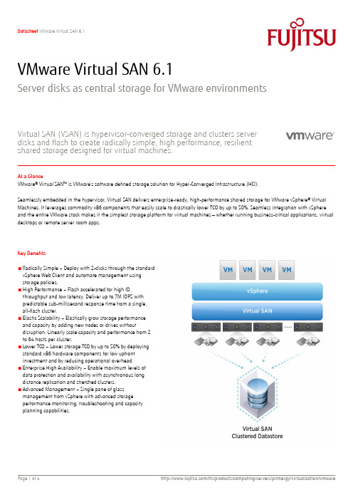
VMware Virtual SAN 6.1Server disks as central storage for VMware environmentsVirtual SAN (VSAN) is hypervisor-converged storage and clusters server disks and flash to create radically simple, high performance, resilient shared storage designed for virtual machines.At a GlanceVMware® Virtual SAN™ is VMware’s software defined storage solution for Hyper-Converged Infrastructure (HCI).Seamlessly embedded in the hypervisor, Virtual SAN delivers enterprise-ready, high-performance shared storage for VMware vSphere® Virtual Machines. It leverages commodity x86 components that easily scale to drastically lower TCO by up to 50%. Seamless integration with vSphere and the entire VMware stack makes it the simplest storage platform for virtual machines — whether running business-critical applications, virtual desktops or remote server room apps.Key Benefits■ Radically Simple – Deploy with 2-clicks through the standard vSphere Web Client and automate management using storage policies.■ High Performance – Flash accelerated for high IOthroughput and low latency. Deliver up to 7M IOPS with predictable sub-millisecond response time from a single, all-flash cluster.■ Elastic Scalability – Elastically grow storage performance and capacity by adding new nodes or drives withoutdisruption. Linearly scale capacity and performance from 2 to 64 hosts per cluster.■ Lower TCO – Lower storage TCO by up to 50% by deploying standard x86 hardware components for low upfront investment and by reducing operational overhead. ■ Enterprise High Availability – Enable maximum levels of data protection and availability with asynchronous long distance replication and stretched clusters. ■ Advanced Management – Single pane of glass management from vSphere with advanced storage performance monitoring, troubleshooting and capacityTopicsWhat is VMware Virtual SAN?VMware Virtual SAN is VMware’s software-defined storage solution for hyper-converged infrastructures, a software-driven architecture that delivers tightly integrated compute, networking and shared storage from a single, virtualized PRIMERGY server. Virtual SAN delivers high performance, highly resilient shared storage by clusteringserver-attached flash devices and/or hard disks (HDDs). Virtual SAN delivers enterprise-class storage services for virtualized production environments along with predictable scalability and all-flash performance — all at a fraction of the price of traditional, purpose-built storage arrays. Just like vSphere, Virtual SAN provides users the flexibility and control to choose from a wide range of hardware options and easily deploy and manage it for a variety of IT workloads and use cases. Virtual SAN can be configured as all-flash or hybrid storage. Architecture and Performance: Uniquely embedded within the hypervisor kernel, Virtual SAN sits directly in the I/O data path. As a result, Virtual SAN is able to deliver the highest levels of performance without taxing the CPU with overhead or consuming high amounts of memory resources, as compared to other storage virtual appliances that run separately on top of the hypervisor. Virtual SAN can deliver up to 7M IOPS with an all-flash storage architecture or 2.5M IOPS with a hybrid storage architecture.Scalability: Virtual SAN has a distributed architecture that allows for elastic, non-disruptive scaling from 2 to 64 hosts per cluster. Both capacity and performance can be scaled at the same time by adding a new host to the cluster (scale-out); or capacity and performance can be scaled independently by merely adding new drives to existing hosts (scale-up). This “Grow-as-you-Go” model provides linear and granular scaling with affordable investments spread out over time. Management and Integration: Virtual SAN does not require any additional software to be installed—it can be enabled in a few, simple clicks. It is managed from the vSphere Web Client and integrates with the VMware stack including features like vMotion®, HA, Distributed Resource Scheduler™ (DRS) and Fault Tolerance (FT) as well as other VMware products such as VMware Site Recovery Manager™, VMware vRealize™ Automation™ and vRealize Operations™.Automation: VM storage provisioning and storage service levels (e.g. capacity, performance, availability) are automated and controlled through VM-centric policies that can be set or modified on-the-fly. Virtual SAN dynamically self-tunes, adjusting to ongoing changes in Key Features and CapabilitiesKernel embedded– Virtual SAN is built into the vSphere kernel, optimizing the data I/O path to provide the highest levels of performance with minimal impact on CPU and memory resources.All-Flash or hybrid architecture– Virtual SAN can be used in all-flash architecture for extremely high and consistent levels of performance or in a hybrid configuration to balance performance and cost.Expanded enterprise-readiness– support for vSphere Fault Tolerance, asynchronously replicating VMs across sites based on configurable schedules of up to 5 minutes, continuous availability with stretched clusters and major clustering technologies including Oracle RAC and Microsoft MSCS.Granular non-disruptive scale-up or scale-out– Non-disruptively expand the capacity of the Virtual SAN data-store by adding hosts to a cluster (scale-out) to expand capacity and performance or disks to a host (scale-up) to add capacity or performance.Single pane of glass management with vSphere– Virtual SAN removes the need for training on specialized storage interfaces or the overhead of operating them. Provisioning is now as easy as two clicks.VM-centric policy-based management– Virtual SAN uses storage policies, applied on a per-VM basis, to automate provisioning and balancing of storage resources to ensure that each virtual machine gets the specified storage resources and services.Virtual SAN Stretched Cluster– Create a stretched cluster between two geographically separate sites, synchronously replicating data between sites and enabling enterprise-level availability where an entire site failure can be tolerated, with no data loss and near zero downtime. Advanced management– Virtual SAN Management Pack for vRealize Operations delivers a comprehensive set of features to help manage Virtual SAN, including global visibility across multiple clusters, health monitoring with proactive notifications, performance monitoring and capacity monitoring and planning. The Health Check Plug-in complements the management pack for additional monitoring including HCL compatibility check and real-time diagnostics.Server-side read/write caching– Virtual SAN minimizes storage latency by accelerating read/write disk I/O traffic with built-in caching on server-side flash devices.Built-in failure tolerance– Virtual SAN leverages distributed RAID and cache mirroring to ensure that data is never lost if a disk, host, network or rack fails.Deployment OptionsCertified Hardware: Control your hardware infrastructure by choosing from certified components on the hardware compatibility list, see /resources/compatibility/search.php?deviceCat egory=vsanPRIMEFLEX for VMware VSAN: Select a pre-configured hardware solution that is certified to run Virtual SAN. More information under:/global/products/computing/integrated-systems/ vmware-vsan.htmlVMware System RequirementsVirtual SAN certified:■1GB NIC; 10GB NIC recommended■SATA/SAS HBA or RAID controller■At least one flash caching device and one persistent storage disk (flash or HDD) for each capacity-contributing nodeClusterMinimum cluster size: two hostsSoftware■One of the following: VMware vSphere 6.0 U1 (any edition), VMware vSphere with Operations Management™ 6.1 (any edition), or VMware vCloud Suite® 6.0 (any edition updated with vSphere 6.0U1)■VMware vCenter Server™ 6.0 U1Additional hintWhen the Fujitsu 2GB UFM Flash Device is used as a boot device for VMware ESXi (vSphere) an additional local HDD is mandatory to store trace files and core dumps generated by VSAN. Such small HDD has to be connected to the onboard SAS/SATA controller and is not part of the VSAN storage.PRIMERGYFollowing PRIMERGY Servers are released for VMware software: VMware Systems Compatibility HCL:/go/hclFujitsu Manageability with ServerView SuiteServerView is able to manage PRIMERGY servers by means of the CIM provider that Fujitsu has integrated for VMware vSphere▪Management of the physical machine under the host operating system ESXi▪ServerView RAID for configuration and management of the RAID controllers in the physical machine▪Management of the virtual machines under the guest operating systems Windows and Linux▪Remote access via onboard Integrated Remote Management▪SupportMandatory Support and Subscription (SNS)SNS (Support and Subscription) is mandatory for at least 1 year for all VMware software products. Fujitsu offers its own support for VMware OEM software products. This support is available for different retention periods and different support levels. The Fujitsu support levels are: Platinum Support (7x24h) or Gold Support (5x9h). Both service levels can be ordered either for 1, 3 or 5 year support terms. Please choose the appropriate Support for your project.Your support agreement is with Fujitsu and VMware exclusively through Fujitsu (not with VMware directly). SNS is only for Fujitsu servers like PRIMERGY and PRIMEQUEST. Of course, SNS for VMware (OEM) software products can be renewed at Fujitsu prior to the end of the SNS term. SNS for VMware (OEM) software products cannot be renewed at VMware directly.Support Terms and ConditionsFujitsu Terms and Conditions can be found under:FUJITSU ServiceContract SoftwareFUJITSU Support Pack SoftwareTechnical Appendix VMware SoftwareFujitsu Professional ServiceInstallation, configuration or optimization services for VMware software are optional service offerings. Additionally operations services from Fujitsu are available. Any additional and optional service can be requested from Fujitsu Professional Services.Product Activation Code RegistrationPlease register your activation code at/code/fsc.Registration will generate the license key. Help can be found at: /support/licensing.html.If you have any problems, you can send an email to*********************.WarrantyClass: CConditionsThis software product is supplied to the customer under the VMware conditions as set forth in the EULA of the VMware software at/download/eula/.More informationIn addition to VMware software, Fujitsu provides a range of platform solutions. They combine reliable Fujitsu products with the best in services, know-how and worldwide partnerships. Fujitsu PortfolioBuilt on industry standards, Fujitsu offers a full portfolio of IT hardware and software products, services, solutions and cloud offering, ranging from clients to datacenter solutions and includes the broad stack of Business Solutions, as well as the full stack of Cloud offerings. This allows customers to select from alternative sourcing and delivery models to increase their business agility and to improve their IT operation’s reliability. Computing Products/global/products/computing /Software/software/To learn more about VMware vSphere please contact your Fujitsu sales representative, Fujitsu business partner, or visit our website. /ftsFujitsu Green Policy Innovation is ourworldwide project for reducing burdens on the environment.Using our global know-how, we aim to contribute to the creation of a sustainable environment for future generations through IT.Please find further information at/global/about/environ mentAll rights reserved, including intellectual property rights. Changes to technical data reserved. Delivery subject to availability. Any liability that the data and illustrations are complete, actual or correct is excluded. Designations may be trademarks and/or copyrights of the respective manufacturer, the use of which by third parties for their own purposes may infringe the rights of such owner.For further information see/fts/resources/navigati on/terms-of-use.html©2015 Fujitsu Technology Solutions GmbHTechnical data is subject to modification and delivery subject to availability. Any liability that the data and illustrations are complete, actual or correct is excluded. Designations may be trademarks and/or copyrights of the respective manufacturer, the use of which by third parties for their own purposes may infringe the rights of such owner.Phone: +49 5251/525-2182 Fax : +49 5251/525-322182E-mail:*************************.com Website: /fts 2015-11-30 EN。
ASP.NETCoreWebAPI教程-ProjectConfiguration

Core 应用程序本质是一个控制台应用程序,它通过创建 web 服务器来托管应用程序并监听传入的HTTP请求,然后返回响应,所 以程序的入口还是 Program 类的 Main() 方法, Core Web API 应用程序中的 Program 如下:
"CompanyEmployees": { "commandName": "Project", "launchBrowser": true, "launchUrl": "weatherforecast", "applicationUrl": "https://localhost:5001;http://localhost:5000", "environmentVariables": { "ASPNETCORE_ENVIRONMENT": "Development" }
public class Program {
public static void Main(string[] args) {
CreateHostBuilder(args).Build().Run(); }
public static IHostBuilder CreateHostBuilder(string[] args) => Host.CreateDefaultBuilder(args) .ConfigureWebHostDefaults(webBuilder => { eStartup<Startup>(); });
public class Startup {
ibm_utl_sguide_9.30-win2k03-08_anyos_x86-64

2 Connect to the RSAII, MM,or AMM Web Management Interface (via Web browser)
3 Click on Task "Remote Control"
4 Start Remote Control, it will open second Web Browser Window
to do selections in ServerGuide graphical user interface.
- The same CD/DVD Drive used for ServerGuide CD needs to be use
for Windows CD/DVD.
o Instructions for running ServerGuide via remote disk feature:
detecting installed options and proServerGuide wizard detects the server model and installed
adapters; then, the wizard guides you through setup,
The supported systems for three versions of IBM ServerGuide are listed
in IBM ServerGuide page, refer to section 7.0 of this readme.
3.0 Remote Installs Support
- Supports the installation of 64bit Windows Server 2008 that is on a
OfficeScan常见问题解决方案解读

OfficeScan常见问题解决方案解决方案65945officescan 8.0在WEB登入控制台问题描述: 在IE里面出现http://{officescan server ip}/officescan/console/cgi/cgiwebupdate.exe解决方案: 1,停止以下的服务OfficeScan Master ServiceIIS Admin Service2、打开Program Files\Trend Micro\OfficeScan\PCCSRV\Web_OSCE\Web_console\HTML\ClientInstall文件夹检查以下的文件是否为0字节,如果是0字节,请从其他运行正常的officescan服务器端上获取NTsetup0.htmNTsetup1.htmNTsetup2.htmNTsetup3.htmNTsetup4.htmNTsetup4e.htm3、打开\Program Files\Trend Micro\OfficeScan\PCCSRV\Admin文件夹,检查tsc.ptn文件是否存在,如不存在,从运行正常的officescan上拷一个过来4、开启步骤一中停止的两个服务5、进入C盘\Windows 文件夹,右击temp文件夹,属性,把IUSR_帐号加入,并且给与读写权限6、再次进行安装解决方案65549Officescan 8.0 通过Web方式安装客户端出现空白页面。
问题描述: Officescan 8.0 通过Web方式安装客户端出现空白页面。
解决方案: 请尝试在Officescan服务器进行下面的操作:1. 点击运行,输入cmd然后回车。
2. 输入以下命令netsh winsock reset解决方案65890officescan master service无法自动启动问题描述: officescan master service无法自动启动,可以手动启动。
汽车开发项目常用英语缩写对照

缩写中文解释3C 3个关键零件(缸体、缸盖、曲轴)4 VDP四阶段的汽车发展过程A/D/V分析/发展/验证AA审批体系ABS防抱死制动系统ACD实际完成日期AI人工智能AIAG汽车工业产业群ALBS装配线平衡系统AP提前采购API先进的产品信息APM汽车加工模型APQP先进的产品质量计划AR拨款申请ARP拨款申请过程ARR建筑必要性检查ASA船运最初协议ASB船运第二个协议ASI建筑研究启动ASP船运标准协议ASR建筑选择审查B&U 土建公用BCC品牌特征中心BEC基础设计内容BI开始冒气泡B-I-S最佳分节段BIW白车身BOD设计清单BOM原料清单BOP过程清单CAD计算机辅助设计CAE计算机辅助工程(软件)CAFÉ公司的平均燃油经济CAM计算机辅助制造CAMIP持续汽车市场信息项目CARE用户接受度审查和评估CAS概念可改变的选择CDD成分数据图CGS公司图形系统CI提出概念CIT隔间融合为组CKD完全拆缷CMM坐标测量仪CMOP结构管理工作计划CPP关键途径CPP关键途径CR&W控制/机器人技术和焊接CRIT中心新产品展示执行组CS合同签订CTS零件技术规格D/EC设计工程学会DAP设计分析过程DCAR设计中心工作申请DDP决策讨论步骤DES设计中心DFA装配设计DFM装配设计DLT设计领导技术DMA经销商市场协会DMG模具管理小组DOE试验设计DOL冲模业务排行DQV设计质量验证DRE设计发布工程师DSC决策支持中心DVM三维变化管理DVT动态汽车实验E/M进化的EAR工程行为要求ECD计划完成日期EGM工程组经理ELPO电极底漆ENG工程技术、工程学EOA停止加速EPC&L工程生产控制和后勤EPL 工程零件清单ETSD对外的技术说明图EWO工程工作次序FA最终认可FE功能评估FEDR功能评估部署报告FFF自由形态制造FIN金融的FMEA失效形式及结果分析FTP文件传送协议GA总装GD&T几何尺寸及精度GM通用汽车GME通用汽车欧洲GMIO通用汽车国际运作GMIQ通用汽车初始质量GMPTG通用汽车动力组GP通用程序GSB全球战略部HVAC加热、通风及空调I/P仪表板IC初始租约ICD界面控制文件IE工业工程IEMA国际出口市场分析ILRS间接劳动报告系统IO国际业务IPC国际产品中心IPTV每千辆车的故障率IQS初始质量调查IR事故报告ISP综合计划ITP综合培训方法ITSD内部技术规范图IUVA国际统一车辆审核KCC关键控制特性KCDS关键特性标识系统KO Meeting 启动会议KPC关键产品特性LLPRLOI 意向书M&E 机器设备MDD成熟的数据图MFD金属预制件区MFG制造过程MIC市场信息中心MIE制造综合工程师MKT营销MLBS物化劳动平衡系统MMSTS制造重要子系统技术说明书MNG制造工程MPG试验场MPI主程序索引MPL主零件列表MPS原料计划系统MRD物料需求日期MRD 物料需求时间MSDSMSE制造系统工程MSS市场分割规范MTBF平均故障时间MTS生产技术规范MVSS汽车发动机安全标准NAMA北美市场分析NAO北美业务NAOC NAO货柜运输NC用数字控制NGMBP新一代基于数学的方法NOA授权书NSB北美业务部OED组织和员工发展P.O 采购订单PA生产结果PAA产品行动授权PAC绩效评估委员会PACE项目评估和控制条件PAD产品装配文件PARTS零件准备跟踪系统PC问题信息PCL生产控制和支持PDC证券发展中心PDM产品资料管理PDS产品说明系统PDT产品发展小组PED产品工程部PEP产品评估程序PER人员PET项目执行小组PGM项目管理PIMREP事故方案跟踪和解决过程PLP生产启动程序PMI加工建模一体化PMM项目制造经理PMR产品制造能要求PMT产品车管理小组POMS产品指令管理小组POP采购点PPAP生产零部件批准程序PPAP 生产件批准程序PPH百分之PPM百万分之PR绩效评估PR 采购需求PR/R问题报告和解决PSA 潜在供应商评估PSC部长职务策略委员会PTO第一次试验PUR采购PVM可设计的汽车模型PVT生产汽车发展QAP质量评估过程QBC质量体系构建关系QC质量特性QFD质量功能配置QRD质量、可靠性和耐久力QS质量体系QUA质量RC评估特许RCD必须完成日期RFQ报价请求RFQ 报价要求书RONA净资产评估RPO正式产品选项RQA程序安排质量评定RT&TM严格跟踪和全程管理SDC战略决策中心SF造型冻结SIU电子求和结束SL系统规划SMBP理论同步过程SMT系统管理小组SOP生产启动,正式生产SOR要求陈述SOR 要求说明书SOW工作说明SPE表面及原型工程SPO配件组织SPT专一任务小组SQC供方质量控制SQIP供应商质量改进程序SSF开始系统供应SSLT子系统领导组SSTS技术参数子系统STO二级试验SUW标准工作单位TA 技术评估TAG定时分析组TBD下决定TCS牵引控制系统TDMF文本数据管理设备TIMS试验事件管理系统TIR试验事件报告TLA 技术转让协议TMIE总的制造综合工程TOE总的物主体验TSM贸易研究方法TVDE整车外型尺寸工程师TVIE整车综合工程师TWS轮胎和车轮系统UAW班组UCL统一的标准表UDR未经核对的资料发布UPC统一零件分级VAPIR汽车发展综合评审小组VASTD汽车数据标准时间数据VCD汽车首席设计师VCE汽车总工程师VCRI确认交叉引用索引VDP汽车发展过程VDPP汽车发展生产过程VDR核实数据发布VDS汽车描述概要VDT汽车发展组VDTO汽车发展技术工作VEC汽车工程中心VIE汽车综合工程师VIS汽车信息系统VLE总装线主管,平台工程师VLM汽车创办经理VMRR汽车制造必要条件评审VOC顾客的意见VOD设计意见VSAS汽车综合、分析和仿真VSE汽车系统工程师VTS汽车技术说明书WBBA全球基准和商业分析WOT压制广泛开放WWP全球采购PC项目启动CA方案批准PA项目批准ER工程发布PPV产品和工艺验证PP预试生产P试生产EP工程样车Descriptions3 Critical Parts(Cylinder-block, Cylinder-head, Crankshaft) Four Phase Vehicle Development ProcessAnalysis/Development/ValidationApprove ArchitectureAnti-lock Braking SystemActual Completion DateArtificial IntelligenceAutomotive Industry Action GroupAssembly Line Balance SystemAdvanced PurchasingAdvanced Product InformationAutomotive Process ModelAdvanced Product Quality PlanningAppropriation RequestAppropriation Request ProcessArchitectural Requirements ReviewAgreement to Ship AlphaAgreement to Ship BetaArchitecture Studies InitiationAgreement to Ship PrototypeArchitecture Selection ReviewBuilding & UtilityBrand Character CenterBase Engineered ContentBubble Up InitiationBest-In-SegmentBody In WhiteBill of DesignBill of MaterialBill of ProcessComputer-Aided DesignComputer-Aided EngineeringCorporate Average Fuel EconomyComputer-Aided ManufacturingContinuous Automotive Marketing Information Program Customer Acceptance Review and EvaluationConcept Alternative SelectionComponent Datum DrawingsCorporate Graphic SystemConcept InitiationCompartment Integration TeamComplete KnockdownCoordinate Measuring MachinesConfiguration Management Operating PlanCorporate Product PorefolioCritical Path PlanControls/Robotics & WeldingCenter Rollout Implementation TeamContract SigningComponent Technical SpecificationDesign and Engineering CouncilDesign Analysis ProcessDesign Center Action RequestDecision Dialog ProcessDesign CenterDesign for AssemblyDesign For ManufacturabilityDesign leader TechnicalDealer Market AssociationDie Management GroupDesign Of ExperimentsDie Operation Line-UpDesign Quality VerificationDesign Release EngineerDecision Support CenterDimensional Variation ManagementDynamic Vehicle TestEvolutionary/MajorEngineering Action RequestEstimated Completion DateEngineering Group ManagerElectrode position PrimerEngineeringEnd of AccelerationEngineering Production Cntrol &Logistics Engineering Parts ListExterior Technical Specification Drawing Engineering Work OrderFinal ApprovalFunctional EvaluationFunctional Evaluation Disposition Report Free Form FabricationFinancialFailure Mode and Effects AnalysisFile Transfer ProtocolGeneral AssemblyGeometric Dimensioning & Tolerancing General MotorsGeneral Motors EuropeGeneral Motors International Operations General Motors Initial QualityGeneral Motors Powertrain GroupGeneral ProcedureGlobal Strategy BoardHeating, Ventilation ,and Air Conditioning Instrument PanelInitiate CharterInterface Control DocumentIndustrial EngineeringInternational Export Market AnalysisIndirect Labor Reporting SystemInternational OperationsInternational Product CenterIncidents Per Thousand VehiclesInitial Quality SurveyIncident ReportIntegrated Scheduling ProjectIntegrated Training ProcessInterior Technical Specification DrawingInternational Uniform Vehicle AuditKey Control CharacteristicsKey Characteristics Designation SystemKick-off MeetingKey product CharacteristicLing Lead P ReleaseLetter of IntentMachine & EquipmentMaster Datum DrawingsMetal Fabrication DivisionManufacturing OperationsMarketing Information CenterManufacturing Integration EngineerMarketingMaterial Labor Balance SystemManufacturing Major Subsystem Technical Specifications Manufacturing EngineeringMilford Proving GroundMaster Process IndexMaster Parts ListMaterial Planning SystemMaterial Required DateMaterial Required DateMaterial Safery Data SheetsManufacturing System EngineerMarket Segment SpecificationMean Time Between FailuresManufacturing Technical SpecificationMotor Vehicle Safety StandardsNorth American Market AnalysisNorth American OperationsNAO ContainerizationNumerically ControlledNext Generation Math-Based ProcessNotice of AuthorizationNAO Strategy BoardOrganization and Employee DevelopmentPurchasing OrderProduction AchievementProduction Action AuthorizationPerformance Assessment CommitteeProgram Assessment and Control EnvironmentProduct Assembly DocumentPart Readiness Tracking SystemProblem CommunicationProduction Control and LogisticsPortfolio Development CenterProduct Data ManagementProduct Description SystemProduct Development TeamProduction Engineering DepartmentProduct Evaluation ProgramPersonnelProgram Execution TeamProgram ManagementProject Incident Monitoring and Resolution Process Production Launch ProcessProcess Modeling IntegrationProgram Manufacturing ManagerProduct Manufacturability RequirementsProduct Management TeamProduction Order Management SystemPoint of PurchaseProduction Part Approval ProcessProduction Parts Approval ProcessProblems Per HundredProblems Per MillionPerformance ReviewPurchase RequirementProblem Reporting and ResolutionPotential Supplier AssessmentPortfolio Strategy CouncilPrimary TryoutPurchasingProgrammable Vehicle ModelProduction Vehicle DevelopmentQuality Assessment ProcessQuality Build ConcernQuality CharacteristicQuality Function DeploymentQuality, Reliability,andDurabilityQuality SystemQualityReview CharterRequired Completion DateRequest For QuotationRequirement for QuotationReturn on Net AssetsRegular Production OptionRouting Quality AssessmentRigorous Tracking and Throughout Managment Strategic Decision CenterStyling FreezeSumming It All UpSystem LayoutsSynchronous Math-Based ProcessSystems Management TeamStart of ProductionStatement of RequirementsStatement of RequirementsStatement of WorkSurface and Prototype EngineeringService Parts OperationsSingle Point TeamStatistical Quality ControlSupplier Quality Improvement ProcessStart of System FillSubsystem Leadership TeamSubsystem Technical Specification Secondary TryoutStandard Unit of WorkTechnology AssessmentTiming Analysis GroupTo Be DeterminedTraction Control SystemText Data Management FacilityTest Incident Management SystemTest Incident ReportTechnology License AgreementTotal Manufacturing Integration Engineer Total Ownership ExperienceTrade Study MethodologyTotal Vehicle Dimensional EngineerTotal Vehicle Integration EngineerTire and Wheel SystemUnited Auto WorkersUniform Criteria ListUnverified Data ReleaseUniform Parts ClassificationVehicle & Progress Integration Review Team Vehicle Assembly Standard Time Data Vehicle Chief DesignerVehicle Chief EngineerValidation Cross-Reference IndexVehicle Development ProcessVehicle Development Production Process Verified Data ReleaseVehicle Description SummaryVehicle Development TeamVehicle Development Technical OperationsVehicle Engineering CenterVehicle Integration EngineerVehicle Information SystemVehicle Line ExecutiveVehicle Launch ManagerVehicle and Manufacturing Requirements Review Voice of CustomerVoice of DesignVehicle Synthesis,Analysis,and Simulation Vehicle System EngineerVehicle Technical SpecificationWorldwide Benchmarking and Business Analysis Wide Open ThrottleWorldwide PurchasingProgram CommencementConcept ApprovalPrograme ApprovalEngineering ReleaseProduct & Process ValidationPre-PilotPilotAAR 外观件批准报告ADV 分析/开发/验证ADV P&R ADV计划和报告ADV-DV ADV设计验证ADV-PV ADV产品验证AIAG 汽车工业行为集团AP 先期采购APO 亚太分部APQP 产品质量先期策划ASQE 先期供应商质量工程师BOM 材料清单BOP 过程清单Brownfield Site 扩建场地CMM 三坐标测试仪CPK 过程能力指数CTS 零件技术规范Defect outflow detection 缺陷检测DFM/DFA 可制造性/可装配性设计DPV 每辆车缺陷数DRE 设计发放工程师EQPE 工程质量规划工程师Error Occurrence Prevention 设计发放工程师EWO 工程更改指令FE1,2,3 1,2,3功能评估FMEA 失效模式和后果分析GD&T 几何公差&尺寸GM 通用汽车公司GME 通用汽车工期欧洲分部GP 总体步骤GP-4 生产件批准程序GP-5 供应商质量过程和测量(问题回复及解决)GP-8 持续改进GP-9 按节拍生产GP-10 试验室认可程序GP-11 样件批准GP-12 早期生产遏制GPDS 全球产品描述系统GPS 全球采购系统GQTS 全球质量跟踪系统GR&R 量具的重复性与再现性Greenfield Site 新建工厂GVDP 全球车辆开发过程IPTV 每千辆车缺陷数KCC 关键控制特性KCDS 关键特性指示系统Kick-off Meeting 启动会议KPC 关键产品特性LAO 拉丁美洲分部Layered Process Audit 分层审核LCR 最低生产能力Mcomplex system/subassembly M复杂系统/分总成MCR 最大生产能力MOP 制造/采购MPC 物料生产控制MPCE 欧洲物料生产控制MRD 物料需求日期(交样完成日期)MSA 测量系统分析MVBns(原:NS) 非销售车制造验证MVBs(原:S) 销售车制造验证N.O.D. 决议通知NAO 北美分部NBH 停止新业务OEM 主机客户PAD 生产装配文件PC&L 生产控制&物流PDT 产品开发小组FMEA 潜在失效模式分析PPAP 生产件批准程序PPK 过程能力指数PPM (1)项目采购经理(2)每百万件的产品缺陷数PPO 样车试制工程PQC 产品质量特性PR/R 问题报告及解决PSA 潜在供应商评审PTR 零件试生产QSA 质量系统评审QTC 工装报价能力RASIC 负责,批准,支持,通知,讨论RFQ 报价要求RPN 风险顺序数RPN reduction plan 降低RPN值计划S.T.E.P 采购定点小组评估过程SDE 供应商开发工程师SFMEA 系统失效模式分析SMT 系统管理小组SOA 加速开始SOP 正式生产SOR 供应商质量要求声明SPC 统计过程控制SPO 零件与服务分部SQ 供应商质量SQE 供应商质量工程师SQIP 供应商质量改进过程SSF 系统填充开始SSTS 分系统技术规范Team feasibility commitment 小组可行性承诺UG UG工程绘图造型系统VAP 每辆车开发过程VLE 车辆平台负责人WWP 全球采购旧称呼IV2 新称呼OTS旧称呼MC1 新称呼FE2旧称呼MC2 新称呼FE3旧称呼MCB 新称呼FE1旧称呼PVV 新称呼Trgout。
Summary of this chapter
Chapter from book Effective software Maintenance and Evolution: Reuse-based Approach, Copyright (C) 2007 Stan Jarzabek Chapter 5 Evolution of versions and configuration managementSummary of this chapter:We move on now from the maintenance of the function of the system’s code (considered in Chapters 2 and 3) and of the functionality of the application (considered in Chapter 4) to the evolution of the system’s code and of a sequence of system releases. Software Configuration Management (SCM) is “the discipline of controlling the evolution of complex software systems” [18]. SCM tools [5] are commonly used in industry to manage software changes, in particular to support evolution. SCMs store the history of component versions and their configurations, created in the response to evolutionary changes. Each system release is a configuration of component versions stored in an SCM repository.Software Configuration Management (SCM) tools [5][18] are commonly used in industry to manage software changes, in particular to support evolution. SCMs store the history of component versions and their configurations, created in the response to evolutionary changes. In this Chapter, we go through an example of software evolution with Concurrent Versions System (CVS) (/cvs/). Concurrent Versions System (CVS) is probably the most widely used SCM tool in industry, especially in the development of open source projects [9]. CVS is based on concepts of a pioneering and highly influential RVC [17].We focus on some typical situations that arise during evolution, and try to address them with CVS. We observe that some of the evolution problems, notably explosion of similar component versions, are difficult to avoid as long as evolution is managed in terms of specific component versions.5.1 A working example: FRS evolutionThe example of the Facility Reservation System (FRS) was introduced in Chapter 1. Its functions and multiple versions are now briefly summarized. Facility Reservation System (FRS) helps users reserve facilities such as meeting rooms. FRS users manage (add, delete and modify) their own reservations or reservations requested by others (middleman). We briefly discussed an FRS evolution example in Chapter 1. For ease of reference, we repeat FRS description here, with some more details.The following FRS features are discussed in the evolution example described in this Chapter: •VIEW-RES: reservation viewing methods:-FAC: view reservations by facility-RES-ID: view reservations by reservation ID-DATE: view reservations by date-USER: view reservations by user-USR-PD: view reservations made for only preferred range of dates•BR: block reservation – making reservations in bulk•PAY: charges for reserving facilities•BRD: discount for block reservationsFigure 1 shows the FRS evolution scenario in our study. Circled numbers attached to FRS releases indicate the order in which the releases were implemented. Solid arrows between releases X and Y indicate that X was chosen as a baseline for Y. Dashed arrows between releases X and Y indicate that some features implemented in X were adapted for Y.Figure 1. Stages in FRS evolutionWe illustrate evolution of FRS according to scenario depicted in Chapter X, supported by the evolution history stored in the CVS repository.Stage 1: Suppose one of our customers requests a new feature, to view reservations by date(DATE, for short). Having implemented the required enhancement, we have two versions of the FRS in use, namely the original FRS and the enhanced system FRS DATE.Stage 2: After some time, yet another customer would like to view reservations by user (USER). Having implemented this new enhancement, we have three versions of the FRS in use: the original FRS, FRS DATE and FRS USER.Stage 3: We also realize that the new features may be generally useful for other customersand yet another version FRS DATE,USER may make perfect sense to some of them.Stage 4: Sometimes later, a new customer wants an FRS that supports the concept of paymentfor reservations (PAY). This includes computing and displaying reservation charges (RC),cancellation charges (CC), bill construction (BC) and Frequent Customer Discount (FCD).Name PAY refers to all such payment features. FRS DATE,USER,PAY results from thatenhancement.Stage 5: Another customer would like to make block reservations (BR), as well as support for payment (FRS DATE,USER, PAY,BR)Stage 6: We include block reservation discount (FRS DATE,USER,PAY,BR,BRD).Stage 7: We need an FRS with existing features USER and BR (FRS USER,BR).Stage 8: A customer asks us to customize the USER feature to view reservations made for only preferred range of dates ((FRS USER-PD,BR).Analysis of FRS requirements and implementation revealed the following dependencies among features:•DATE ~i↔USER (mutually implementation-independent features)•PAY ~f↔BR (mutually functionally-independent features)•PAY i↔ BR•PAY iÆ {DATE, USER}•PAY iÆ FRS (meaning that most of FRS components are implementation-dependent on PAY)•{BR, PAY} fÆ BRDAnalysis of FRS requirements and implementation revealed the following dependencies among features:•DATE ~i↔USER (mutually implementation-independent features)•PAY ~f↔BR (mutually functionally-independent features)•PAY i↔ BR•PAY iÆ {DATE, USER}•PAY iÆ FRS (meaning that most of FRS components are implementation-dependent on PAY)•{BR, PAY} fÆ BRD5.2 FRS component architectureA component architecture, design assumptions, implementation technologies as well as underlying platforms (such as J2EE or .NET) define the context within which software is evolved. A software architecture is described by a set of components that interact one with another through well defined interfaces (connectors) to deliver the required system behavior. In this Chapter, we focus on components only, and will address connectors in Chapter X. FRS components are organized into three tiers, namely the user interface, business logic and database tiers, depicted in Figure 2. In the architecture terminology, a ‘tier’ is just a large granularity component that may contain many smaller components. Each tier provides services to the tier above it and serves requests from the tier below. User interface (UI) components allow FRS administrators and reservation requestors to interact with the system to manage users, facilities and reservations. The UI components handle the initialization, display and event-handling for the various Java panels used in reservation, user and facility management. The server, business logic (BL) tier, defines the functionality of the FRS to accomplish various actions. Server components provide the actual event-handling code for the various user interface widgets (e.g., buttons). There are also components that set up and shut down connections with the DBMS component. The database stores data related to users, facilities and reservations. The database tier is responsible for providing data access and storage services to the business logic tier. the database components include tables or databases to store data related to users, facilities and reservations.FRS is implemented in EJB™ and Java, with MySQL as the database server.Figure 2. Tiers and component groups in FRS architectureFRS is structured as follows: FRS consists of subsystems, modules and components to manage reservations (Reservation), facilities (Facility) and users (User). Each module (e.g., ViewRes to view reservations), is implemented by a user interface component (ViewRes-UI), and business logic component (ViewRes-BL).Shaded boxes in Figure 2 denote component groupings in FRS subsystems as follows: Reservation-UI: all the user interface components for the Reservation subsystemReservation-BL: all the business logic components for the Reservation subsystemFacility-UI: all the user interface components for the Facility subsystemFacility-BL: all the business logic components for the Facility subsystemUser-UI: all the user interface components for the User subsystemUser-BL: all the business logic components for the User subsystemTable 1 shows some of modules and components in user interface and business logic tiers.Table 1. FRS component architecture: user interface and business logic tiers Subsystem Modules User interface components Business logic components Reservation ViewRes ViewRes-UI ViewRes-BLCreateRes CreateRes-UICreateRes-BL DeleteRes DeleteRes-UI DeleteRes-BL UpdateRes UpdateRes-UI UpdateRes-BL Facility ViewFac ViewFac-UI ViewFac-BLCreateFac CreateFac-UI CreateFac-BL DeleteFac DeleteFac-UI DeleteFac-BL UpdateFac UpdateFac-UI UpdateFac-BL User ViewUser ViewUser-UI ViewUser-BLCreateUser CreateUser-UI CreateUser-BL DeleteUser DeleteUser-UI DeleteUser-BL UpdateUser UpdateUser-UI UpdateUser-BL5.3 Evolution of FRS with CVSCVS keeps track of versions of source code files, documents and other software artifacts resulting from changes applied to software during evolution. Versions of software artifacts are stored under unique identifiers. Each version of a software artifact may branch into sub-versions, as shown in Figure 3.Figure 3. Version tree of ViewRes-UI FRS componentEach system release is defined as a configuration of specific versions of system components. Besides usual SCM capabilities such as version control, CVS also performs conflict resolution and provides check in/out facilities to assist parallel development. Here, we concentrate only on version control and management of system releases. We store component versions and their configurations that occurred in released systems in a CVS repository. Each such component (or component configuration) accommodates some combination of variant features. Typically, components are files. The following is a development life-cycle for a new system release, S NEW :1. Analyze requirements for S NEW .2. Understand similarities/differences among S NEW and earlier releases.3. Select from the CVS repository configurations of component versions “best matching” S NEW . We call this S NEW component baseline .4.Customize the selected component baseline to fully meet requirements of the S NEW.5.Test and integrate customized components to obtain S NEW.6.Validate S NEW to see if it meets its requirements.We may need to iterate over the above life-cycle, changing component selection or their customization, even revising some of the requirements, until we obtain an acceptable S NEW.In this study, we focus on issues related to component selection (Step 3) and customization (Step 4). These two activities have much impact on productivity of programmers during evolution: The quality of selection determines the follow up customization effort. In sub-sections below, we analyze typical problems developers must solve during these two steps. Our analysis is based on the evolution scenario depicted in Figure 1.5.4 Reuse of features implemented in past releases when building new system releasesReuse of features already implemented in past releases is the main concern when selecting components. Based on CVS release history, selecting components “best matching” a newly built system release is a problem in itself. We must take into account both functionality as well as the follow up customization and integration effort.We start with FRS DATE,USER. We can build FRS DATE,USER by (1) selecting FRS DATE and then customizing it according to FRS USER, or vice versa, (2) selecting FRS USER and then customizing it according to FRS DATE. If we choose scenario (1), the customization effort is a combined effort of:•finding components affected by feature USER in FRS USER, and extracting relevant code, •analyzing the impact of feature USER on FRS DATE ,•implementing feature USER on FRS DATE.Since feature USER has been implemented in FRS USER, we would like to reuse feature implementation in FRS DATE,USER. For illustration, we show steps involved in scenario (1):1.Select a previous version of FRS as a starting point. Here, we choose FRS DATE .2.Retrieve version FRS USER. We make use of this version to update the FRS DATE, rather thanto re-implement USER feature from scratch.3.Extract business logic action to “view reservation by user” from FRS USER and modifyReservationManager component.4.Extract use interface code to “view reservations by user” and code to call the business logic action to “view reservation by user” from FRS USER and modify reservation user interface, Reservation-UI, accordingly.For implementation-independent features, such as DATE and USER, the above steps are quite simple and are accomplished by branch and merge (‘update’ command) facilities of CVS. As all the implications of scenarios (1) and (2) on evolution are the same, we conclude that it makes no difference if we choose (1) or (2).Should scenarios (1) and (2) require different customizations to accommodate the new feature, the logical choice would be to pick components from FRS release(s) in which adding the new feature requires less customization effort. A number of issues may complicate the follow up customization, and therefore, may have impact on the right selection of components. In particular:A)features DATE and USER might have different impact on FRS components; for example,DATE could affect more components and in more complicated ways than USER; or implementation of feature USER might be well documented, while implementation of DATE might be missing,B)DATE might be implementation-dependent on USER, but USER might also beimplementation-independent of DATE,C)DATE might be implementation-dependent on yet other features that are not relevant toUSER,D)feature DATE might have been modified in FRS DATE in a way that is not required for FRS USER.All of the above considerations could affect the customization effort of (1) vs. (2), and should be taken into the account when selecting the component baseline for FRS DATE,USER .We now illustrate point C) above. Suppose, we have already implemented features f1 and f2 in releases FRS f1 and FRS f1,f2, and would like to have feature f1 and new feature f3 in release FRS f1,f3. Intuitively, we would pick FRS f1 as the closest configuration, since for FRS f1,f2, we would have to remove f2 before adding in f3. This would probably be the right selection if f3 and f2 were not similar to each other. However, if f3 was similar to f2, FRS f1,f2 would be a better choice, as it would be easy to turn f2 into f3. We see an instance of this situation when implementing FRS USER, with the initial FRS and FRS DATE as starting points. Since features DATE and USER are similar, we should pick FRS DATE as an FRS USER baseline.The usual situation is that any new system release, say S NEW, may include many features implemented in variant forms in past releases. Variant forms of the same feature stem from implementation dependencies among features. Existing features may be also implementation-dependent on new features required in S NEW. The following example illustrates reuse of features in view of implementation-dependencies among them. In developing FRS USER,BR, we select FRS USER as our baseline and add BR (block reservation) to it. As BR has been implemented only in FRS DATE,USER,PAY,BR previously, we make use of this implementation. The customization of FRS USER includes:1.Finding components affected by feature BR in FRS DATE,USER,PAY,BR, and extracting relevantcode,2.Analyzing the impact of feature BR on FRS USER ,3.Implementing feature BR on FRS USER.In Step 1, the code extracted for BR is inclusive of code to calculate payment for BR. In Step 2, we realize that the code needed for BR here should be independent of code for PAY (payment). This causes a conflict with code extracted in Step 1, as implementation of BR was according to the implementation dependency PAY i↔ BR (payment and block reservation are mutually implementation-dependent) previously. Thus in Step 3, we are unable to reuse BR directly. The parts where PAY was involved in BR need to be removed. If information on modifications made for PAY in BR is not available, implementation becomes more difficult. Upon implementation, a new variant form of BR is produced.Suppose, we have picked a configuration of component versions that we believe make a good baseline for a new release, and removed unwanted features (if any) from that configuration. To add in new features, we fetch the previous version that contains a given feature, and extract the relevant code from that version. Reuse of features is hindered by the fact that thesame feature may be implemented differently in different system releases. The implementation of a feature may span many system components. The process of (possibly) retrieving many versions of feature implementation and extracting correct portions of feature implementation may be tedious and time consuming. Tools such as ‘diff’ and Bonsai [3] are typically used to aid in feature extraction and reuse. However, ‘diff’ shows all the differences between two files, not modifications relevant to a specific feature. If it is too difficult to reuse a feature from a previous version, a feature must be implemented from scratch, increasing redundancy and complexity.The above discussion shows that, at times, the knowledge of already implemented features and of feature similarities may not be readily available from the CVS repository. We can improve the situation by linking logical groupings of detailed changes done to system components to relevant source of change (e.g., a request for a new feature or for a modification of a certain feature in some system release). The concept of a “change set” has been introduced in SCM research [5][13][14], and is available in some SCMs (e.g., Synergy/CM [16]). In CVS, we can do frequent check-in/check-out to avoid intermixing in any single component version multiple changes done for different purposes. This can help in extracting feature implementation. Enumerating “change sets” corresponding to inter-dependent features, especially in the presence of variant ways in which the same feature can be implemented in different system releases, may produce a complicated web of information that may pose nontrivial problems for effective feature reuse and modification. In Part II, we describe an alternative way of addressing these problems, with mixed-strategy mechanisms capable of representing changes and affected components in a unified, generic form, amenable to automation.We also tried to address the above problems with external documentation. For example, we recorded code lines inserted/deleted/modified with respect to a baseline. Such documentation can help when we deal with simple situations such as reusing implementation of feature DATE to build FRS USER, but in other cases, different information may be required. For example, when modifying FRS DATE to accommodate USER feature and build FRS DATE,USER, we would only need to modify the lines that differ between the two, as both DATE and USER are implemented in a similar way. As there are possibly many other different cases to consider, the external documentation complementing the information we can get from the CVS repository would have to vary to cater for those nuances. In addition, there are well-known problems with keeping documentation up to date with evolving programs. A study of software development in two industries [6] showed that, despite the fact that documentation comprised of thousands of pages, selected components often implemented requirements insufficiently or turned out to be incompatible.The process of selecting components to minimize customization effort may be quite complicated. Much information has to be repeatedly extracted but is not explicitly represented in the evolution history stored in the CVS repository. As it is difficult to see all the implications of component selection, often the choice of components for customization is suboptimal, leading to high cost of evolution.Deelstra et al. [6] mention that, using such an approach, “development effort is spent on implementing functionality that highly resembles the functionality already implemented in reusable assets or in previous projects.” In their case studies, it was observed that product derivation at a company comprised the selecting of several hundreds of components, and thisoccasionally led to a situation where components were not found, though they were present. Many of the functionalities, though already implemented in earlier releases, could not be reused and had to be re-implemented all over again.5.5 Adding new features to a system releaseThe new feature is either a completely different from the existing features or it is similar to an existing feature. A completely different feature must be implemented from scratch, as no previous knowledge of that feature exists. This situation was observed when developing FRS DATE,USER,PAY,BR. We selected FRS DATE,USER,PAY as a component baseline for implementing a new feature BR (block reservation). However, PAY (payment feature) and BR are mutually implementation-dependent: PAY i↔ BR. The customization of FRS DATE,USER,PAY includes:1.Implementing the BR feature while adding code to calculate payment for BR,2.Modifying the PAY feature to accommodate specific needs of block reservation.We end up with 2 variant forms for PAY: PAY implemented without BR in FRS DATE,USER,PAY, and PAY implemented with BR in FRS DATE,USER,PAY,BR.We can save effort (and also enhance the clarity of the design) if we implement similar features in a similar way. FRS DATE illustrates a simple case. DATE (view-by-date) is similar to the FAC (view-reservation-by-facility) method implemented in the initial FRS. The customization effort includes:1.Finding components affected by feature FAC in FRS, and extracting relevant code,2.Customizing copied code to obtain DATE .Recognizing similar features based on the information stored in CVS, especially in relation to feature dependencies, is not easy.5.6 Selective propagation of new features to past releasesTo accommodate a new feature into past releases, we must upgrade each release separately, taking into account unique feature dependencies that may exist in different releases.The propagation process is time-consuming, error-prone and contributes to component version explosion.Consider the case of FRS USER-PD,BR. USER-PD (view-by-user for a preferred date) is a slight modification of the USER (view-by-user) reservation method. The feature USER-PD is implemented by simply customizing code for USER. The same modifications must be manually implemented in every other system release that wishes to include PD feature.5.7 The visibility of changes during evolutionThe visibility of changes is hindered by feature dependencies and the fact that implementation of a feature may span many components. To illustrate how implementation-dependencies affect the visibility of changes, we show steps involved in enhancing FRS DATE,USER,PAY with feature BR (features PAY and BR are mutually implementation-dependent: PAY i↔ BR):1.Add an option for selecting block reservations to the reservation user interface menu inReservation-UI components.2.Add options for selecting different block reservation methods (reserving multiple facilitiesor multiple time slots) to the Reservation-UI. Upon selection an option, the user is asked toprovide input needed for that option.3.Add code to call block reservation methods for each option. Add an option to delete blockreservations in the menu of Reservation-UI, and code for deleting block reservations in arelevant business logic component.4.Calculate the payment for block reservation.5.Modify Payment component to accommodate block reservation as follows: add methods tocalculate the total cost of all the block reservations, store the reservation cost in a vector(rather than a single value as it was the case of a single reservation), and store the totalnumber of block reservations.In Step 4, we modify code for BR to deal with payment. In Step 5, we modify code for PAYto accommodate BR. Changes are embedded into the code and we can’t discriminate amongparts of the code in BR that have been modified to accommodate PAY and vice-versa.In FRS DATE,USER,PAY,BR,BRD, block reservation discount is functionally dependent on both blockreservation and payment: {BR, PAY} fÆ BRD, in addition to the implementation dependency mentioned above. Steps to implement this FRS release are as follows:1.Modify code in PAY (payment). For BR (block reservation), different calculations areneeded due to BRD (block reservation discount).2.Modify code in block reservation methods to inform the user that BRD is included, whencalculating payment.As before, it is not clear which modifications relate to a feature in question (BRD, in thiscase). However, the difficulty is more severe now, due to the complicated dependencies. InStep 2, to modify PAY, we must first find code for BR in PAY, and then embed the code forBRD in the midst of it. Similarly, in Step 2, we embed code for BRD into the code for PAY inBR.5.8 Explosion of variant features and feature dependenciesIn studies described in [6] it was observed that even small changes to interfaces led to newcomponent versions. This was also observed in our case study. For example, we created eight1) versions of component Reservation-UI, as each FRS release ( Figurerequired some modifications of that component. Feature dependencies also caused componentversions to multiply. For example, component Payment had three different versions: PAYimplemented alone, PAY implemented with BR, and PAY with BR and BRD.As more variant features are added, the number of component versions explodes. Just addingsix features (DATE, USER, PAY, BR, BRD, USER-PD) to the FRS, produced 22 newcomponent versions.A technique sometimes used to limit version explosion is to add features in a permanent way,and to control their availability in a specific system installation using runtime parameters. Asthis technique addresses the problem at the program implementation rather than at the designlevel, it leads to complex programs. This approach also results in larger resource footprintwith “dead code” which may be undesirable. An example of a solution trying to address thisproblem is Koala [15].The problem of explosion of similar component versions seems to be inherent in object/component technologies [1][2][10][11][12]. While supporting techniques can be used to extract change information from the component history [5], [8], [9], these techniques deal with symptoms rather than attack the root of the problem.summary5.9 AReuse of existing features and propagation of new features in CVS is based on extraction of relevant code from past releases, using the CVS update operation. When a component is modified, only the differences between the original version and a modified one are stored to minimize storage. However, different versions of the same component are treated as different entities in the sense that a change done in version 1 of a component A will not be reflected in version 2 of component A. Therefore, changes meant for many component versions must be manually propagated to versions in question, taking into account possible subtle variations in change implementation across component versions, not to mention the likelihood of making errors. Reuse of existing and new features is therefore tedious, time consuming, and error prone.Table 2. Summary of evolution stagescommentsStage #modFRS DATE 3 SimpleimplementationimplementationFRS USER 3 SimpleFRS DATE,USER 3 Simple code extraction from theprevious versionFRS DATE,USER,PAY35 Implementation is not difficult thoughit affects many componentsFRS DATE,USER,PAY,BR9 Difficult to see where code was addedfor BR in PAY and vice versa.FRS DATE,USER,PAY,BR,BRD 3 Difficult to see relationship betweenfeatures.FRS USER,BR12 Difficulty in extracting the BR codewithout PAYFRS USER-PD,BR 4 Simple customization of USERmethod.Tools such as ‘diff’ and Bonsai [3] are helpful, but ‘diff’ shows all the differences between two files, not modifications relevant to a specific feature. When feature dependencies are involved, the modifications needed may be different in each release, and usefulness of ‘diff’ becomes even more problematic. Propagation of new features to past releases also poses problems. Table 2 summarizes modifications of FRS components at various evolution stages. Consecutive changes affecting code over time are absorbed into the code, and it becomes difficult to see relationships among features. The concept of “change set” makes a significant step towards addressing these problems.It is quite significant that we could observe some very basic difficulties despite the simplicity of our case study. These difficulties must necessarily magnify when we move into deeper waters of evolution.5.10 Related WorkAdvanced SCM features [5][13][14] and commercial tools such as Synergy/CM [16] improve the visibility of information that matters in evolution. So do techniques for extracting a release history stored in an SCM repository [7][8][9]. One of such advanced SCM concepts is。
Oracle Access Manager 配置指南说明书

EnterpriseTrack OAM Configuration Guide 16 R1
June t Configuring Oracle Access Manager....................................................................................... 5 Prerequisites..................................................................................................................................... 5
Where: <Webgate_Home> is the Webgate Home directory. For example, /u01/app/Oracle/Middleware/Oracle_OAMWebGate1. <MW_HOME> is oracle middleware home directory, For example, /u01/app/Oracle/Middleware 2) Go to <Webgate_Home>/webgate/ohs/tools/deployWebGate. 3) Run the following: deployWebgateInstance.sh -w <Webgate_Instance_Directory> -oh <Webgate_Oracle_Home> where:<Webgate_Instance_Directory> is the location of Webgate Instance Home <Webgate_Oracle_Home> is the directory where Oracle HTTP Server Webgate is installed and created as the Oracle Home for Webgate. For example, run the following: deployWebgateInstance.sh -w <MW_HOME>/Oracle_WT1/instances/instance1/config/OHS/ohs1 -oh <MW_HOME>/Oracle_OAMWebGate1
Cisco SRW2024 24-Port Gigabit Switch 产品说明书

Data SheetCisco SRW2024 24-Port Gigabit Switch: WebViewCisco Small Business Managed SwitchesHighly Secure, Reliable, Intelligent Switching for Your Growing BusinessesHighlights●24 high-speed ports optimized for the network core or to support bandwidth-intensiveapplications●Enhanced QoS helps ensure a consistent network experience and supports networkedapplications including voice, video, and data storage●Strong security protects network traffic to keep unauthorized users off the network●Simplified, web-based management for easy installation and configurationFigure 1. Cisco SRW2024 24-Port Gigabit Switch: WebViewProduct OverviewGrowing businesses require cost-effective networking solutions that can scale with ever-changing business needs. The Cisco® SRW2024 24-Port Gigabit Switch (Figure 1) brings Gigabit speeds to your users and servers while increasing the intelligence and security of the network infrastructure. The twenty-four 10/100/1000 Mbps ports enable you to take advantage of the Gigabit Ethernet interfaces shipping in the current generation of servers, workstations, and storage devices, in addition to supporting your existing 10/100 Mbps clients. The optional Gigabit optical interfaces allow you to expand the network as your business grows.Network security is a top priority in any size business. Most business data networks, large and small, are unsecure. Unauthorized access to the network and mission-critical data is a constant concern. The Cisco SRW2024 helps secure the network through 802.1X port authentication and MAC filtering. The 802.1X standard requires clients to authenticate themselves before the port will pass data for them.Businesses are recognizing the benefits of voice over IP (VoIP) and are quickly migrating their voice services to IP-based platforms, requiring their local area networks to support both voice and data applications. In unmanaged IP networks, bursty data sessions can disrupt voice packet delivery, causing poor voice quality. With the enhanced quality of service (QoS) and traffic-management features in the Cisco SRW2024, voice data can be prioritized, helping ensure clear and reliable voice communications.Taking advantage of the advanced features of the Cisco SRW2024 can further secure the integrity of your network. The WebView interface provides an intuitive, highly secure management interface, enabling you to better utilize the comprehensive feature set of the switch, for a better-optimized, more secure network.Features●Twenty-four 10/100/1000 switched RJ-45 ports with auto medium dependent interface(MDI) and MDI crossover (MDI-X) cable detection● 2 mini Gigabit Interface Converter (mini-GBIC) slots for fiber and copper Gigabit Ethernetexpansion (shared)●Nonblocking, store-and-forward switching mechanism●Simplified QoS management enabled by advanced queuing techniques using 802.1p,differentiated services (DiffServ), or type of service (ToS) prioritization schemes enhances the performance of real-time applications such as voice and video●Configuration and monitoring from a standard web browser with WebView management●Secure remote management of the switch via Secure Shell (SSH) and SSL secure channelnetwork protocols●802.1Q-based VLANs enable segmentation of networks for improved performance andsecurity●Private VLAN Edge (PVE) for simplified network isolation of guest connections orautonomous networks●Automatic configuration of VLANs across multiple switches through Generic VLANRegistration Protocol (GVRP) and Generic Attribute Registration Protocol (GARP)●Automatic port configuration through auto MDI/MDIX and 802.1ab with Link LayerDiscovery Protocol (LLDP) and Universal Plug and Play (UPnP) support●User/network port-level security via 802.1X authentication and MAC-based filtering●Increased bandwidth (up to 8x) and added link redundancy with Link Aggregation ControlProtocol (LACP)●Enhanced rate-limiting capabilities provide control, including back pressure to control therate at which data can flow into and out of a port●Multicasting, broadcasting, and flooding control●Port mirroring for noninvasive monitoring of switch traffic●Jumbo frame support (10 KB)●Simple Network Management Protocol (SNMP) versions 1, 2c, and 3 and RemoteMonitoring (RMON) support●Fully rack mountable using the included rack-mounting hardwareSpecificationsTable 1 contains the specifications, package contents, and minimum requirements for the Cisco SRW2024 24-Port Gigabit Switch.Table 1. Specifications for the Cisco SRW2024 24-Port Gigabit Switch: WebViewSpecificationsStandards IEEE 802.3, 802.3u, 802.3ab, 802.3x, 802.1p, 802.1QPorts Twenty-four 10/100/1000 RJ-45 ports and 2 shared Mini-GBIC slotsCabling type Category 5 Ethernet or betterLEDs System, Link/Activity, GigabitPerformanceSwitching capacity 48 Gbps, nonblockingMAC table size 8000Number of VLANs 256 - staticManagementWeb user interface Built-in web user interface for easy browser-based configuration (HTTP/HTTPS)SNMP SNMP versions 1, 2, and 3 with support for trapsSNMP MIBs RFC1213 MIB-2, RFC2863 interface MIB, RFC2665 Ether-like MIB, RFC1493 bridge MIB,RFC2674 extended bridge MIB (P-bridge, Q-bridge), RFC2819 RMON MIB (groups 1,2,3,9only), RFC2737 entity MIB, RFC 2618 RADIUS client MIBRMON Embedded RMON software agent supports 4 RMON groups (history, statistics, alarms, andevents) for enhanced traffic management, monitoring, and analysis.Firmware upgrade ●Web browser upgrade (HTTP)●Trivial File Transfer Protocol (TFTP) upgradePort mirroring Traffic on a port can be mirrored to another port for analysis with a network analyzer orRMON probeOther management ●RFC854 Telnet (menu-driven configuration)●SSH and Telnet management●Telnet client●SSL security for web user interface●Switch audit log●Dynamic Host Configuration Protocol (DHCP) client●BOOTP●Simple Network Time Protocol (SNTP)●Xmodem upgrade●Cable diagnostics●Ping●TracerouteSecurity FeaturesIEEE 802.1X 802.1X - RADIUS authentication; MD5 encryptionAccess control lists (ACLs) ●Differentiated services code point (DSCP)/IP precedence-based class of service (CoS)●IPv6 traffic-class-based CoS●IP address●Subnet mask●Protocol●Service type●MAC address●VLAN ID●TCP/ User Datagram Protocol (UDP) portAvailabilityLink aggregation ●Link aggregation using IEEE 802.3ad LACP●Up to 8 ports in up to 8 trunksStorm control Broadcast, multicast, and unknown unicastSpanning Tree IEEE 802.1d Spanning Tree, IEEEE 802.1s Multiple Spanning Tree, IEEE 802.1w RapidSpanning Tree, Fast LinkoverIGMP snooping IGMP (versions 1 and 2) snooping provides for fast client joins and leaves of multicaststreams and limits bandwidth-intensive video traffic to only the requestors.QoSPriority levels 4 hardware queuesScheduling Priority queuing and weighted round-robin (WRR)Class of service ●Port based●802.1p VLAN priority based●IP ToS/differentiated services code point (DSCP) based●IPv4 and IPv6 traffic class basedRate limiting Ingress policer, egress shaperLayer 2VLAN ●Port-based and 802.1Q-based VLANs●PVE●Management VLANHead-of-line (HOL) blocking HOL blocking preventionJumbo frame Supports frames up to 10 KBDynamic VLAN GVRP - dynamic VLAN registrationStandards 802.3i 10BASE-T Ethernet, 802.3u 100BASE-TX Fast Ethernet, 802.3ab 1000BASE-TGigabit Ethernet, 802.3z Gigabit Ethernet, 802.3x flow controlEnvironmentalDimensions W x H x D 16.93 x 1.75 x 13.78(430mm x 44.5mm x 350mm)Unit weight 7.54 lbs (3.42kg)Power 100-240V, 50-60Hz, internal, universalCertification FCC Part 15 Class A, CE Class A, UL, cUL, CE mark, CB Operating temperature 0˚ to 40˚C (32˚ to 104˚F)Storage temperature -20˚ to 70˚C (-4˚ to 158˚F)Operating humidity 10% to 90%Storage humidity 10% to 95%Package Contents●Cisco SRW2024 24-Port Gigabit Switch●AC power cord●Rack-mounting kit with brackets and hardware●CD with user guide in PDF format●Registration card●Console cableMinimum Requirements●Category 5 Ethernet network cable●TCP/IP installed on each computer within the network●Network adapter installed in each computer●Network operating system (Windows, Linux, Mac OS X)Product Warranty5-year limited hardware warranty with return to factory replacement and 90-day limited software warrantyCisco Limited Warranty for Cisco Small Business Series ProductsThis Cisco Small Business product comes with a 5-year limited hardware warranty with return tofactory replacement and a 90-day limited software warranty. In addition, Cisco offers softwareapplication updates for bug fixes and telephone technical support at no charge for the first 12months following the date of purchase. To download software updates, go to:/go/smallbiz.Product warranty terms and other information applicable to Cisco products are available at/go/warranty.For More InformationFor more information on Cisco Small Business products and solutions, visit:/smallbusiness.Printed in USA C78-502265-02 03/10。
2021年华为5G认证考试题库(含答案)

2021年华为5G认证考试题库(含答案)单选题(总共182题)1.NSA网络中,以下哪一层的统计最接近用户的体验速率?A、RRC层B、RLC层C、物理层D、PDCP层答案:D2.在NSA组网中,以下哪个定时器或常量不会用于下行链路检测?A、T301B、T310C、N300D、N310答案:C3.一NR小区SSB波束采用默认模式,天线挂高35米,机械下倾角为3°,数字下倾配置为0°,则此小区主覆盖波瓣的下沿(近点)距离基站大约是多少米?A、1200米B、330米C、150米D、670米答案:B4.NSA架构中,B1事件的门限值是如何发给UE的? A、通过Pss/SssB、通过RRC重配置信令C、通过OSI消息D、通过PBCH广播答案:B5.以下哪项是NR中的基本调度单位?A、REB、REGC、CCED、PRB答案:D6.如果出现了NSA接入失败,以下哪类问题可以通过性能指标做统计,并且可以统计相应的失败原因?A、eNodeB不发起gNodeB添加B、gNodeB拒绝添加请求C、UE无MR上报D、UE在eNodeB侧随机接入失败答案:B7.在切换准备过程中,源小区基于以下哪个参数确定切换的目标小区?A、频点B、NCGIC、PCID、TAC答案:C8.以下关于下行频率资源分配的描述,错误的是哪项?A、支持type0和type1两种分配方式B、type0是RBG粒度的分配方式,支持非连续分配和连续分配C、type0是RB粒度的分配方式,仅支持非连续分配D、type1是RB粒度的分配方式,仅支持连续分配答案:C9.5GRAN2.164T64R的AAU可以最多支持多少种广播波束场景配置?A、17B、3C、8D、5答案:A10.在NR用户上行速率测试中,对2T4R的终端,建议“上行最大MIMO层数”建议配置为以下哪项?A、Laver2B、Laver1C、Layer3D、Layer4答案:A11.以下哪种SRS的资源仅用于高频组网?A、NoncodebookB、BeammanagementC、CodebookD、Antennaswitching答案:D12.在NR辅站变更成功后,MeNodeB会通知MME以下哪条信令?A、PathUpdateProcedureB、RRCConnectionReconfigurationpleteC、SgNBInformationTransferD、SgNBReconfigurationplete答案:A13.做5G的C波段上行链路估算时,UE的发射功率一般为多少?A、26dBmB、30dBmC、33dBmD、23dBm答案:D14.如果需要开启干扰随机化调度,那么站内三个小区的PCI需要满足什么原则A、PCImod3错开B、PCImod8错开C、PCImod6错开D、PCImod4错开答案:A15.在NSA接入过程中,如果gNodeB收到了“additionrequest”消息,但是没有回复任何消息,以下哪项是可能的原因?(单选)A、gNodeB检测到X2链路故障B、无线资源不足C、gNodeB检测到s1链路故障D、License资源不足答案:A16.在同频切换的A3事件参数中,以下哪个参数不能基于QCI进行单独配置?A、A3偏置B、邻区偏置(CIO)C、A3幅度迟滞D、A3时间迟滞答案:B17.以下信道或信号中,发射功率跟随PUSCH的是哪项?A、PUCCHB、PUSCHC、PRACHD、SRS答案:A18.以下关于最小速率保障的描述,错误的是哪项?A、如果当前业务平均速率高于最小保障速率,基站会降低调度优先级B、如果当前业务平均速率低于最小保障速率,基站会提升调度优先级C、该参数不是3GPP规范的标准参数D、该参数是用于non-GBR业务答案:B19.Rel15版本中,5GPUSCH的最大码字数是多少个?A、4B、2C、1D、3答案:C20.以下关于SSB波束数量的描述,A、低频场景最个B、SA组网下,实际的波束数量通过SIB1消息下发C、最大的波束数量只和频段因素相关D、高频场景最4个答案:A21.在SIB1消息中,如果前导期望功率为-100dbm,SSB发射功率为18dbm,当前RSRP为-90dbm,那么终端第一个PRACH的前导发射功率是多少?A、10dBmB、-108dBmC、8dBmD、-118dBm答案:C22.针对60KHZ的SCS配置,一个无线帧中包含了多少个时隙?B、80C、160D、20答案:A23.RAN3.0,异频切换使用那个事件触发?A、A3B、A4C、A5D、A6答案:C24.在NR组网下,为了用户能获得接近上行最高速率,其MCS值最低要求应该是多少?A、16B、32C、25D、2025.以下关于PRACH的Scs描述,错误的是哪一项?A、短格式PRACH的SCS必须和PUSCHI的Scs一样B、长格式PRACH的SCs和PUSCH的scs一定不一样C、长格式PRACH采用固定的Scs,无法配置D、短格式PRACH的SCS可以配置,通过SIB1消息下发答案:A26.在5GC中,以下哪个模块用于用户的鉴权管理?A、ANFB、AUSFC、PCFD、SMF答案:B27.为了解决NR网络深度覆盖的问题,以下哪项措施是不可取的? A、采用低频段组网B、使用Lampsite提供室分覆盖C、增加NR系统带宽D、增加AAU发射功率答案:C28.NR触发A3事件的条件是以下哪项?A、Mn+Ofn-Hys>Ms+Ofs+OffB、Mn+Ofn+Ocn>Ms+Ofs+OcsC、Mn+Ofn+Ocn+HysD、Mn+Ofn+ocn-Hys>Ms+Ofs+Ocs+off答案:D29.在同频小区重选过程中,如果想实现终端从服务小区到某个特定邻区重选更容易,那么该如何修改参数?A、增加QoffsetB、增加QhystC、减小QoffsetD、诚小Qhyst答案:C30.以下哪种SCs不允许用于SSB?A、60KHzB、30KHzC、120KHzD、15KHz答案:A31.在NSA组网中,如果在eNodeb例配置的5GSSB频点和实际的不一致,会出现以下哪个问题?A、gnodeb拒地添加请求B、enodeb无法下发NR的测量配置C、UE随机接入失败D、UE无法上报5G测量结果答案:C32.以下关于PRACH虚警的描述,正确的是哪一项?A、U2020可以支持PRACH根序列冲突检测功能,降低虚警概率B、只要邻区之间PRACH信道时频位置相同,就会导致根序列冲突C、如有PRACH虚警问题,可以调整PRACH功控参数解决虚警问题D、只要邻区之间的PRACH前导序列有重复,就会导致根序列冲突答案:A33.5GCPE接收机的NoiseFigure(NF)典型值为哪项?A、1dBB、5dBC、7dbD、3dB答案:C34.gNOdeB通过PDCCH的DCI格式Uo/U1调整TPC取值,DCI长度是多少? A、4bitB、2bitC、3bitD、1bit答案:B35.64T64RAA支持的NR广播波束的水平3dB波宽,最大可以支持多少?A、65°B、90°C、45°D、110°答案:D36.每个终端最大可以配置多少个专用BWP?A、2个B、8个C、4个D、16个答案:C37.如果采用32T32R.100MHz带宽,MU-MIMO8流场景下,使用eCPRI接口所需要的带宽是多少?A、25GbpsB、50GbpsC、10GbpsD、100Gbps答案:C38.以下哪种UCI信息只能通过周期的PUCCH资源进行发送?A、PMIB、SRC、CQID、ACK-NACK答案:B39.NSA锚点切换流程中使用的是以下哪种事件报告?A、A4B、A3C、A5D、A6答案:B40.以下哪个参数不会出现在SCG的配置消息中?A、T304B、RSRP最小接收电平C、SSB发射功率D、SSB频点答案:C41.以下哪个场景属于NR基于非竞争的随机接入?A、初始RRC连接建立B、波束恢复C、RRC连接重建D、上行数据到达答案:B42.在NSA组网中,如果只有5G发送了掉话,那么终端收到的空口消息是以下哪条?A、RRCReleaseB、RRCReconfigurationC、SCGFailueInfoD、RRCReestablishment答案:C43.gNodeB根据UE上报的CQI,将其转换为几位长的MCS?A、4bitB、3bitC、2bitD、5bit44.在PDU会话建立过程中,以下哪个模块负责PCF的选择?A、AUSFB、SMFC、NSSFD、AMF答案:B45.在5G异频重选流程中,终端通过哪个消息获取异频的重选优先级?A、SIB2B、SIB3C、SIB4D、SIB5答案:C46.55SA组网中,以下哪种RC状态转换流程是不支持的?A、RC空闲到RRC连接B、RRC去激活到RRC空闲C、RRC空闲到RRC去激活D、RRC去激活到RRC连接答案:C47.5G中上行一共定义多少个逻辑信道组?A、4B、2D、8答案:D48.如果小区最大发射功率为100W,SCS=30kHZ,带宽为100MHZ,乘用64T64R 的AAU,那么小区基准功率大约为多少?A、31.9dBmB、-3.3dbmC、0dbmD、34dbm答案:B49.MIB消,息中的哪个参数指示了CORRESETO的时域位置?A、ssb-subcarrieroffsetB、systemframemumbetC、PDCCH-configSIB1高4位D、PDCCH-configSIB1低4位答案:C50.以下哪项不是对CPE做NR下行峰值调测时的建议操作?A、时隙配比设置为4:1B、调制阶数设置支持256QAMMIMO层数设置为4流D、把CPE终端放置在离AAU两米处答案:D51.以下几类数传问题中,哪一项不仅仅是空口质量的问题造成的?A、调度次数低B、IBLER高C、RAK低D、MCS低答案:A52.NR小区中,以下哪个指标可以反映UE业务态的覆盖情况?A、SSBRSRPB、CSIRSRPC、PDSCHRSRPD、CSISINR答案:B53.如果NR广播波束配置成水平3dB为65度波束,则对64T64R的AAU来说。
NetApp存储安装、配置和维护手册

文档信息本安装和维护手册为##X定制,为NetApp标准文档之补充.1作业规划步骤12配置步骤32.1设置磁盘归属,创建ROOT卷32.2检查并更新各部件的firmware系统版本152.3检查并更新存储操作系统版本192.4输入软件许可232.5执行SETUP进行初始化设置232.6调整ROOT卷的大小282.7配置VLAN292.8修改HOSTS文件302.9修改/etc/rc文件312.10配置AutoSupport服务332.11配置SSH342.12配置SNMP352.13配置NTP352.14配置MTA362.15配置IPspace362.16配置MultiStore362.17配置CIFS412.18配置ISCSI432.19配置FCP442.20配置NFS452.21配置重复数据删除462.22配置Snaprestore472.23容灾实现Snapmirror513日常维护543.1正常开关机54Page I3.2维护手段543.2.1Filerview 图形管理接口543.2.2命令行<CLI>543.3空间管理:Aggr, Volume和lun的介绍553.4常用命令基本应用553.5日常系统检查553.5.1目测553.5.2例行系统检查553.6autosupport功能简介和配置564故障处理流程584.1支持方式584.1.1NetApp on the web <NOW> site和服务584.1.2GSC< Global Support Center 全球支持中心>58 4.2案例开立流程584.3损坏部件更换流程591 作业规划步骤Page 12 配置步骤配置参数表2.1 设置磁盘归属,创建ROOT卷2.2 检查并更新各部件的firmware系统版本2.3 检查并更新存储操作系统版本2.4 输入软件许可使用license add ######X命令添加许可,全部输入后,使用license命令进行检查.鉴于许可的##性,此处不截屏日志.2.5 执行SETUP进行初始化设置2.6 调整ROOT卷的大小2.7 配置VLAN2.8 修改HOSTS文件2.9 修改/etc/rc文件2.10 配置AutoSupport服务2.11 配置SSH2.12 配置SNMP2.13 配置NTP2.14 配置MTA2.15 配置IPspace2.16 配置MultiStore2.17 配置CIFS2.18 配置ISCSI2.19 配置FCP2.20 配置NFS2.21 配置重复数据删除2.22 配置Snaprestore。
StarWind Virtual Storage Appliance 安装指南说明书
One Stop Virtualization Shop The Hyper-V and KVM hypervisors are no longer supported in StarWind Virtual Storage Appliance.To view the guide on installing StarWind VSA with VMware vSphere, please open the following link StarWind Virtual Storage ApplianceInstallation Guide with Hyper-VJUNE 2018TECHNICAL PAPERV2.0Trademarks“StarWind”, “StarWind Software” and the StarWind and the StarWind Software logos are registered trademarks of StarWind Software. “StarWind LSFS” is a trademark of StarWind Software which may be registered in some jurisdictions. All other trademarks are owned by their respective owners.ChangesThe material in this document is for information only and is subject to change without notice. While reasonable efforts have been made in the preparation of this document to assure its accuracy, StarWind Software assumes no liability resulting from errors or omissions in this document, or from the use of the information contained herein. StarWind Software reserves the right to make changes in the product design without reservation and without notification to its users.Technical Support and ServicesIf you have questions about installing or using this software, check this and other documents first - you will find answers to most of your questions on the Technical Papers webpage or in StarWind Forum. If you need further assistance, please contact us.About StarWindStarWind is a pioneer in storage virtualization and a company that participated in the development of this technology from its earliest days. Now the company is among the leading vendors of software and hardware hyper-converged solutions. The company’s core product is the years-proven StarWind Virtual SAN, which allows SMB and ROBO to benefit from cost-efficient hyperconverged IT infrastructure. Having earned a reputation of reliability, StarWind created a hardware product line and is actively tapping into hyperconverged and storage appliances market. I n 2016, Gartner named StarWind “Cool Vendor for Compute Platforms” following the success and popularity of StarWind HyperConverged Appliance. StarWind partners with world-known companies: Microsoft, VMware, Veeam, Intel, Dell, Mellanox, Citrix, Western Digital, etc.Copyright ©2009-2018 StarWind Software Inc.No part of this publication may be reproduced, stored in a retrieval system, or transmitted in any form or by any means, electronic, mechanical, photocopying, recording or otherwise, without the prior written consent of StarWind Software.ContentsIntroduction (4)Components (5)Virtual Machine requirements (5)Deployment quick steps (6)IntroductionThis document describes the deployment and configuration process of the StarWind Virtual Storage Appliance with Hyper-V.StarWind Linux-based VSA is a good opportunity for users who don't want to change their current infrastructure to quickly deploy StarWind to test features and functionality. Right now we are releasing the new Linux version, compatible with all industry-standard hypervisors: Microsoft Hyper-V, VMware ESXi, Xen and KVM. It includes Web Management Console, so you can use any convenient HTML5-capable browser to check and configure your infrastructure.Additionally, StarWind Virtual Storage Appliance incorporates StarWind vCenter plugin in order to make it even more convenient for VMware users. StarWind VSA is easy in deployment and management – a typical Linux administrator will easily install and maintain it.A full set of up-to-date technical documentation can always be found here, or by pressing the Help button in the StarWind Management Console.For any technical inquiries please visit our online community, Frequently Asked Questions page, or use the support form to contact our technical support department.ComponentsStarWind Virtual Storage ApplianceLinux virtual machine with StarWind Virtual SAN installed.Virtual Machine requirementsStarWind Virtual Storage Appliance VM requires having at least 4 virtual processors with 2 GHz reserved, at least 4 GB of RAM, 3 NIC ports dedicated as separate vSwitches for management, StarWind synchronization and iSCSI traffic to ensure the proper functioning of VSA.NOTE: When using Star Wind with synchronous replication feature inside of a Virtual Machine, it is recommended not to make backups and snapshots of the Virtual Machine with Star Wind Service which could pause the Star Wind Virtual Machine.Pausing the Virtual Machines while Star Wind service under load may lead to split-brain issues in devices with synchronous replication and data corruption.Deployment quick steps1.Download zip archieve that contains StarWind Virtual Storage Appliance for Hyper-V.2.Extract virtual machine files.3.Create New VM using Hyper-V manager.4.Click Next on the first page of the wizard.5.Specify Name and Location of the VM and click Next.6.Choose Generation 1 and click Next.7.Specify the amount of RAM. We recommend to provision at least 4 GB. Click Next.8.Select Management network and click Next.9.Select Use an existing virtual hard disk and specify the path to the StarWind VSAVHDX file. Click Next.10.StarWind VSA VM has been successfully created. Click Finish.11.Right click on previously created VM and open Settings from the dropdown menu.12.Click Add Hardware and select Network Adapter. Click Add.Add Network adapters for iSCSI and Synchronization purposes.13.Click on SCSI controller in Settings window and add new Hard Drive via clicking on Addbutton.Click New.Click Next on the first page of the wizard.Choose VHDX format of the Virtual Disk and click Next.Choose Virtual Hard Disk Type. Click Next.Note that disk size has to be Fixed.Specify the Name and Location of the Virtual Hard Disk and click Next.Choose Create blank disk option. Specify the size of the Virtual Hard Disk.Complete the process by clicking the Finish button.14.In the Settings window go to Processor menu and change the Number of VirtualProcessors. Note that it is recommended to assign 4 Virtual Processors for StarWind Linux VSA.15.By default, StarWind VSA virtual machine will receive IP address automatically via DHCP. Itis recommended to create a DHCP reservation and set a static IP address for this VM. In order to access StarWind VSA from the local network, the virtual machine must haveaccess to the network. In case you do not have a DHCP server, you can connect to the VM using VMware console and configure static IP address manually.16.Now open web browser and enter the IP address of the VM.17.Log into StarWind Virtual Storage Appliance using default credentials:Username: starwindPassword:starwind18.After successful login, press ALT+CTRL+SHIFT combination.StarWind Virtual Storage ApplianceInstallation Guide with Hyper-V 19.Navigate to Settings menu using pop-up sidebar:20.For security reasons, please, change the default password using the correspondingoption and press Update Password button:21.Connect to StarWind VSA via IP assigned to VM by DHCP.Press X in the opened window.22.Browse to Configuration tab and click VSA Storage23.Click Scan Storages and you will see the recently attached Virtual Disk. Click CreateVolume.Once the process is finished, you will see the created volume.Default storage pool will be selected automatically. Click Advanced settings.24.Click VSA Network Settings. Configure NICs for Management, iSCSI and Synchronizationpurposes.25.Click Configure and assign configuration needed for each NIC.26.Preconfiguration process is finished. You can now create StarWind devices and work withthem.For more information on how to work with StarWind devices, follow the link below:https:///resource-library?type=tpYou can find more information about deploying StarWind HyperConverged scenarioshere:https:///starwind-virtual-san-hyper-converged-2-nodes-scenario-2-nodes-with-hyper-v-clusterhttps:///starwind-virtual-san-hyper-converged-2-node-cluster-vmware-vsphereContacts1-617-449-77 17 1-617-507-58 45 1-866-790-26 46 +44 203 769 18 57 (UK) +34 629 03 07 17 (Spain and Portugal)Customer Support Portal:Support Forum:Sales: General Information: https:///support https:///forums ***********************************StarWind Software, Inc. 35 Village Rd., Suite 100, Middleton, MA 01949 USA ©2018, StarWind Software Inc. All rights reserved.。
configurationmanager.connectionstrings 用法 -回复
configurationmanager.connectionstrings 用法-回复ConfigurationManager.ConnectionStrings 是一个C中的类,用于访问配置文件中的连接字符串。
在这篇文章中,我将详细介绍ConfigurationManager.ConnectionStrings 的用法。
ConfigurationManager 是C 中的一个类,它提供了访问应用程序配置文件的方法。
应用程序配置文件是一个XML 文件,用于存储应用程序的配置信息。
通过ConfigurationManager,我们可以轻松地访问和修改配置文件中的数据。
ConnectionStrings 是一个ConfigurationManager 中的属性,它用于访问配置文件中的连接字符串。
连接字符串是用于连接到数据库或其他外部资源的字符串,它包含了连接所需的所有信息,如服务器地址、用户名、密码等。
下面是使用ConfigurationManager.ConnectionStrings 的一步一步指南:第一步:添加引用在使用ConfigurationManager.ConnectionStrings 之前,我们需要在项目中添加对System.Configuration 程序集的引用。
这可以通过在Visual Studio 中右键单击项目,然后选择“添加”->“引用”来完成。
在弹出的对话框中,找到并选中System.Configuration 程序集,然后点击“确定”按钮。
第二步:打开配置文件在访问配置文件中的连接字符串之前,我们首先需要打开配置文件。
配置文件的名称通常是App.config 或Web.config,它位于项目的根目录下。
你可以通过在Visual Studio 中双击这个文件来打开它。
第三步:添加连接字符串在配置文件中,连接字符串被包含在ConnectionStrings 元素中。
configurationmanager.connectionstrings 用法 -回复
configurationmanager.connectionstrings 用法-回复configurationmanager.connectionstrings 是一种在 .NET 环境中管理数据库连接字符串的功能。
连接字符串是用来连接应用程序和数据库之间的信息,包括数据库类型、服务器名称、用户名和密码等。
configurationmanager.connectionstrings 是 .NET Framework 中System.Configuration 命名空间的一个类,它提供了一种方便的方式来读取和操作应用程序的配置信息,特别是数据库连接字符串。
在使用之前,需要将System.Configuration 添加为项目的引用,并在代码中导入命名空间using System.Configuration。
那么,如何使用configurationmanager.connectionstrings 来管理数据库连接字符串呢?下面将一步一步介绍该过程。
第一步:创建配置文件在 .NET 项目中,我们可以通过在项目根目录下添加一个名为"app.config" 或"web.config" 的XML 文件来创建配置文件。
如果是 Web 应用程序,则可以使用"web.config" 文件;如果是桌面应用程序,则可以使用"app.config" 文件。
注意:在创建配置文件时,需要将其命名为"app.config" 或"web.config",否则在读取配置信息时会出错。
第二步:添加配置信息在配置文件中,可以使用configuration 标签来标识配置信息的根节点。
在configuration 标签内,可以使用connectionStrings 标签来定义数据库连接字符串。
例如:xml<?xml version="1.0" encoding="utf-8"?><configuration><connectionStrings><add name="MyDbConnection"connectionString="Server=myServerAddress;Database=myDataBa se;UserID=myUsername;Password=myPassword;Trusted_Connection=Fals e;" providerName="System.Data.SqlClient" /></connectionStrings></configuration>在上述示例中,定义了一个名为"MyDbConnection" 的连接字符串,其中包含了连接服务器、数据库、用户名和密码等信息。
Ruijie Reyee RG-ES200系列交换机Web配置指南说明书
Ruijie Reyee RG-ES200 Series Switches Web-Based Configuration GuideCopyright StatementRuijie Networks©2021Ruijie Networks reserves all copyrights of this document. Any reproduction, excerption, backup, modification, transmission, translation or commercial use of this document or any portion of this document, in any form or by any means, without the prior written consent of Ruijie Networks is prohibited.Exemption StatementThis document is provided “as is”. The contents of this document are subjec t to change without any notice. Please obtain the latest information through the Ruijie Networks website. Ruijie Networks endeavors to ensure content accuracy and will not shoulder any responsibility for losses and damages caused due to content omissions, inaccuracies or errors.PrefaceThank you for using our products.AudienceThis manual is intended for:●Network engineers●Technical support and servicing engineers●Network administratorsObtaining TechnicalAssistance●Ruijie Networks Website: https:///●Technical Support Website: https:///support ●Case Portal: https://●Community: https://●Technical Support Email: *****************************●Skype: *****************************Related DocumentsConventionsThis manual uses the following conventions:Configuration Guide Overview 1 OvervieweWeb is a Web-based management system that manages or configures devices. You can access eWeb via browsers such as Google Chrome.Web-based management involves the Web server and Web client. The Web server is integrated in a device, and is used to receive and process requests from the client, and return processing results to the client. The Web client usually refers to a browser, such as Google Chrome, IE, or Firefox.1.1 ConventionsIn this document:●Texts in bold are names of buttons (for example, Save) or other graphical user interface (GUI) elements (for example,VLAN).●Devices of different models have slightly different functions. This document uses RG-ES218GC-P as an example fordescription.Only RG-ES226GC-P, RG-ES218GC-P, RG-ES209GC-P, RG-ES209C-P, RG-ES205GC-P, and RG-ES205C-P support the PoE function and configuration.Only RG-ES226GC-P, RG-ES218GC-P, RG-ES224GC, and RG-ES216GC support the multi-DHCP alarm function.The device initially adopts an English OS by default. After it is accessed, the device language can be set to the language used by the current browser. A manually set device language has a higher priority than the language of the browser.The cloud status and online upgrade are not supported in the English OS.2 Configuration Guide2.1 PreparationsScenarioAs shown in the figure below, administrators can access the device from a browser and configure the device through the eWeb management system.Deliver or request commands through AJAX.Administrator Return dataWebserviceDeviceDeployment↘Configuration Environment RequirementsClient requirements:●An administrator can log into the eWeb management system from a Web browser to manage the device. The clientrefers to a PC or some other mobile endpoints such as laptops or tablets.●Google Chrome, Firefox, IE9.0 and later versions, and some Chromium-based browsers (such as 360 ExtremeExplorer) are supported. Exceptions such as garble or format error may occur if an unsupported browser is used.●1024 x 768 or a higher resolution is recommended. If other resolutions are used, the page fonts and formats may not bealigned, the GUI is less artistic, or other exceptions may occur.●Ensure that the client IP address is set to be in the same network segment as the device management address. Thenyou can open the browser and enter the device management address to configure the device. When you use the reserved management address 10.44.77.200 of the device, ensure that the client is directly connected to the switch. To log into the eWeb management system, open Google Chrome, enter 10.44.77.200 in the address bar, and press Enter, as shown in the figure below.The device homepage appears by default. In addition, a dialog box is displayed, asking you whether to change the default password. (The factory settings of the device can be modified only after the password is changed as prompted.)2.2 Default Password ConfigurationUnder factory default settings, the eWeb management system displays a prompt, asking you whether to change the password. (You can configure switch functions only after changing the password.)Click OK. The Web management system automatically redirects to the Account Settings page (or you can choose SystemSettings > Account Settings to configure the login password).Enter a new password according to password rules and then click Save. In the displayed dialog box, click OK.may need re-authentication and login.2.3 Introduction to the Web GUIThe figure below shows the Web GUI of RG-ES226GC-P.The Web GUI consists of the left and right portions.The left portion is the menu bar and provides links to all configuration functions of the device, such as Monitoring and VLAN Settings .The right portion is the content area, which is divided into two parts. The upper part displays the port status bar and the Logout button while the lower part displays the content and configuration area. Port status bar:Move the cursor over a port. Basic information about the port (including the port connection status, speed, duplex mode, and flow control status) is displayed. There are uplink and downlink ports. You can click Collapse to hide the port status bar so that a larger content area is displayed for viewing configuration details.Function menu barSwitch port status barSystem information barPort details list and basic function configuration barWhen a port is down, the port icon is grayed out. When a loop occurs on a port, the port icon is displayed inyellow . When a port works properly, the port icon is displayed in green .Description of the content area:Texts in orange indicate a description of a function. Texts in red indicate notes of a function. A question mark (?) against an orange background indicates an operation prompt, and the prompt pops up when the cursor ismoved over thequestion mark.3 eWeb Configuration3.1 HomepageThe homepage displays basic information about the device, interface status, and VLAN Settings .Move the cursor over the question mark to pop up adescription of the operation.The following figure shows a multi-DHCP alarm displayed on the homepage.Move the cursor over the icon. Alarm information (VLAN, port, IP address, and MAC address) is displayed.3.2 System Settings3.2.1 Device InfoDetails about the device are displayed.Function linkChange the device name.PortconfigurationareaDownlink device search3.2.2 IP SettingsConfigure the management IP address and management VLAN for the device. Auto Obtain IP is set to Enabled by default. When VLAN Settings is set to off, the management VLAN is 1.When VLAN Settings is set to on, the following figure is displayed.When VLAN Settings is set to on, select the management VLAN from configured VLANs (you can choose VLAN Settings > VLAN Members to add a VLAN).The device will be disconnected for a short time during IP address configuration. If Auto Obtain IP is set to Enabled, the device needs to obtain an IP address from the uplink device, or you can enter the management IP address(10.44.77.200) for Web management.After VLAN Settings is set to on, change the management VLAN and check whether the port VLAN contains the management VLAN to avoid inaccessible IP address.3.2.3 Account SettingsThe settings are the same as those in 2.2 Default Password Configuration.When switches are managed via an ad hoc network, no management password can be separately configured for the device and the global password needs to be configured on the master device.3.2.4 RebootClick Reboot to reboot the switch.3.2.5 Upgrade3.2.5.1 Local UpgradeClick Select File. In the displayed dialog box, select a target upgrade package. (The software upgrade package is an xxx.bin file while the system upgrade package is an xxxx.tar.gz file. You need to manually decompress the package and select the xxx.bin file for upgrade.)Keep Old Config is selected by default. If the target version is much later than the current version, it is recommended to uncheck Keep Old Config.3.2.5.2 Online UpgradeOnline upgrade will keep your current configuration. If there is a new version available, the Upgrade button can be clicked. Click the Upgrade button and then confirm upgrade. The device will download the new version from the cloud and upgrade to the target version. The time it takes depends on network performance.3.2.6 Restore DefaultClick Restore to restore factory settings and reboot the device.3.3 Monitoring3.3.1 SwitchesWhen switches are managed by a master device (some functions such as account management are unavailable), the master device of the ad hoc network is displayed. You can access the master device to configure the ad hoc network.The device can discover and display switches in the same management VLAN. The number of discovered switches in a management VLAN varies with the switch model:The following models can discover up to 32 switches in the management VLAN: RG-ES226GC-P, RG-ES218GC-P, RG-ES224GC, and RG-ES216GC.The following models can discover up to 16 switches in the management VLAN: RG-ES205C-P, RG-ES205GC-P, RG-ES209C-P, and RG-ES209GC-P.The first entry shows information about the current device and other entries show information about the discovered devices. You can click an IP address to redirect to the eWeb management of a specific device (login is required).3.3.2 Port StatisticsThe Port Statistics page displays the statistics and status of device ports, such as port Rx/Tx rate and Rx/Tx packets.3.3.3 Cable DiagnosticsYou can learn the general cable status of ports through cable diagnostics, for example, whether a cable is short-circuited or disconnected.Click Start. Test results will be displayed.3.3.4 Loop GuardAfter loop guard is enabled (which is disabled by default), a port causing a loop on the current device will be automatically disabled. After the loop is removed, the port is restored automatically.3.4 Switch Settings3.4.1 Port SettingsOn the Port Settings page, you can configure the port status, speed, duplex mode, and flow control attribute in batches. The page is divided into two parts:Configuration part:Select a port, configure attributes for the port, and then click Save to deliver the configuration to the port.Display part:Configured attributes and actual attributes of each port are displayed.A disabled port cannot transmit or receive packets (the PoE function is not affected). Disabling all ports of a switch willmake the switch unmanageable. Therefore, exercise caution when disabling ports.3.4.2 Port MirroringPort mirroring forwards input/output packets of one or more source port to the destination port to monitor the network.packets. They cannot transmit data to the switch.3.4.3 Port IsolationPort isolation implements layer-2 isolation of packets. After port isolation is enabled (which is disabled by default), data can be forwarded only between uplink ports and downlink ports, and downlink ports cannot forward packets to each other.3.4.4 Static MACThe Static MAC Address page is divided into two parts:Adding a static MAC address:Enter a valid MAC address and VLAN ID, select a port, and then click Add to add a static MAC address.Displaying and deleting a static MAC address:After a valid static MAC address is added, its information is displayed in the list below. Select a static MAC address and cl ick Delete to delete the static MAC address.Up to 16 static MAC addresses can be added.After VLAN Settings is set to off, no VLAN ID needs to be entered to add a static MAC address.3.4.5 Search MACWith the search MAC function, you can search for the MAC addresses learned by the device. MAC addresses can be fuzzily searched. You can enter a part of a complete MAC address (such as 00:74:9c:1e:4b:f4) for searching.After VLAN Settings is set to off, the VLAN ID column will not be displayed.3.4.6 MAC ListThe MAC Address Info page lists MAC addresses learned by the device.Click Clear Dynamic MAC. The device re-obtains the list of learned MAC addresses.After VLAN Settings is set to off, the VLAN ID column will not be displayed.3.4.7 DHCP SnoopingYou can configure the DHCP snooping function for the device.After DHCP Snooping is set to on, as shown in the figure above, the device sets the uplink port as a trusted port by default. You can select a port and click Save to set the port as a trusted port.DHCP Snooping functions as a DHCP packet filter. The DHCP request packets will be forwarded only to the trusted port.The DHCP response packets from only the trusted port will be allowed for forwarding.The port connected to the DHCP server (uplink port) is configured as the trusted port generally.3.5 VLAN SettingsYou can add or delete VLANs, and configure port VLANs (only when VLAN Settings is set to on).3.5.1 VLAN MembersWhen VLAN Settings is set to off, the page is shown in the figure below:When VLAN Settings is set to on, the page is shown in the figure below:After VLAN Settings is set to on, enter a valid VLAN ID and click Add to configure a new VLAN. In the VLAN list, you can select VLANs and click Delete to delete them in batches.Up to 16 VLANs can be configured.A VLAN ID bound to a port cannot be deleted.3.5.2 VLAN SettingsWhen VLAN Settings is set to off, the page is shown in the figure below:When VLAN Settings is set to on, the page is shown in the figure below:The VLAN Settings page is divided into two parts:The upper part enables port VLAN configuration. You can select a port, set the VLAN type (Access or Trunk; when Trunk is selected, Permit VLAN can be configured), Permit VLAN, and Native VLAN, and click Save to save the port VLAN configuration.The lower part lists the port and VLAN settings.Note: Packets from ports in the native VLAN are untagged.3.6 QoS SettingsQoS settings include the port rate and storm control function.3.6.1 Port RateYou can configure the input and output rates for a port. The Port Rate page is divided into two parts:Configuration part:Select one or more ports, set the port type and whether to enable rate limiting (if yes, enter the rate limit value of the port), and click Save.Display part:The input and output rates configured for device ports are displayed.For RG-ES205C-P, the range of the port rate limit is from 1 Mbit/s to 100 Mbit/s.For RG-ES209C-P, the maximum rate is 100 Mbit/s for ports 1–8, and the actual rate is 100 Mbit/s if a greater rate is configured. The range of the port rate limit is from 1 Mbit/s to 1000 Mbit/s for port 9.For RG-ES226GC-P, RG-ES218GC-P, RG-ES205GC-P, and RG-ES209GC-P, the range of the port rate limit is from 1 Mbit/s to 1000 Mbit/s.3.6.2 Storm ControlThe Storm Control page consists of the port storm control configuration and display.Configuration part:Specify the storm control type, select ports, enable storm control, and enter the storm control rate. Click Save to configure storm control.Display part:The storm control types and rates configured for device ports are displayed (when storm control is enabled, the storm control rates are displayed).For RG-ES205C-P, the range of the storm control rate is from 1 Mbit/s to 100 Mbit/s.For RG-ES209C-P, the maximum rate is 100 Mbit/s for ports 1–8, and the actual rate is 100 Mbit/s if a greater rate is configured. The range of the storm control rate is 1 from Mbit/s to 1000 Mbit/s for port 9.For RG-ES226GC-P, RG-ES218GC-P, RG-ES205GC-P, and RG-ES209GC-P, the range of the storm control rate is from 1 Mbit/s to 1000 Mbit/s.3.7 PoE SettingsThe PoE system status and PoE port status of the device are displayed.System status:The total power, used power, remaining power, and work status of the PoE function of the device are displayed.Port status:The PoE voltage, current, power, and current power status of ports are displayed. You can control whether to enable PoE function on a port and restart PDs.Fiber ports (last two ports) of RG-ES226GC-P and RG-ES218GC-P do not support the PoE function.Disabling PoE on a port will stop powering downlink devices connected to the port.Configuration Guide FAQs4 FAQsQ1: What can I do when I failed to log into the eWeb management system?A: Perform the following steps:(1) Check that a PC network cable is correctly connected to a device port and the port indicator blinks.(2) Before accessing the setup GUI, you are advised to configure a static IP address for the PC. Set the IP address to 10.44.77.XXX (for example, 10.44.77.199; the IP address cannot be the same as the device IP address 10.44.77.200) and subnet mask to 255.255.255.0.(3) Run the ping command to test the connectivity between the PC and the device.Q2: What can I do when I forget the device username and password? How can I restore factory settings?If you forget the login password, hold down the Reset button on the panel for 5 seconds after the device is powered on. Factory settings are restored after the device restarts.。
微软公司内部常见缩写
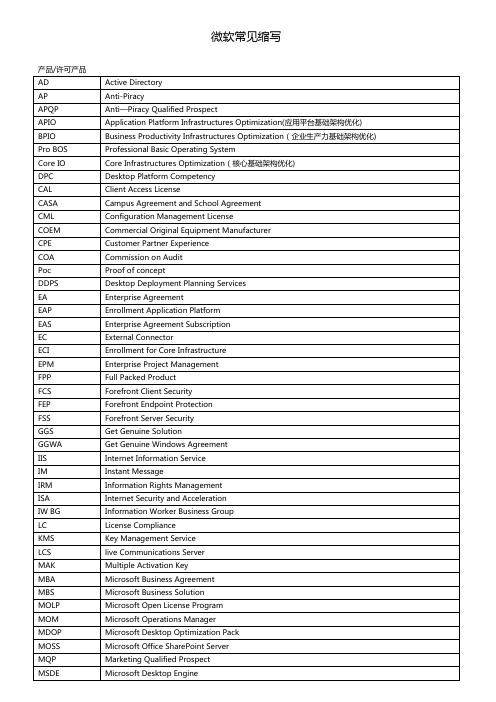
Threat ManagementGateway
UA
UpgradeAdvantage
UC
UnifiedCommunications
UPG
Upgrade
UAC
User AccountControl
VL
Volume License
VLSC
Volume License ServiceCenter
WAT
Pro BOS
Professional Basic Operating System
Core IO
Core Infrastructures Optimization(核心基础架构优化)
DPC
Desktop Platform Competency
CAL
Client Access License
CASA
Campus Agreement and School Agreement
CML
Configuration Management License
COEM
Commercial Original Equipment Manufacturer
CPE
Customer Partner Experience
COA
RMS
Rights Management Service/Server
RTM
Release To Manufacturer
SA
Software Assurance
SBS
Small Business Server
SaaS
Software as a Service
PaaS
Platform as a Service
EC
远程密码分布系统(RCDS)产品说明说明书
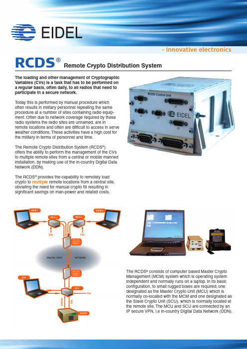
- Innovative electronics RCDS®The loading and other management of CryptographicVariables (CVs) is a task that has to be performed ona regular basis, often daily, to all radios that need toparticipate in a secure network.T oday this is performed by manual procedure whichoften results in military personnel repeating the sameprocedure at a number of sites containing radio equip-ment. Often due to network coverage required by theseradio systems the radio sites are unnamed, are inremote locations and often are difficult to access in serveweather conditions. These activities have a high cost forthe military in terms of personnel and time.The Remote Crypto Distribution System (RCDS®)offers the ability to perform the management of the CVsto multiple remote sites from a central or mobile mannedinstallation, by making use of the in-country Digital DataNetwork (DDN).The RCDS® provides the capability to remotely loadcrypto to multiple remote locations from a central site,obviating the need for manual crypto fill resulting insignificant savings on man-power and related costs.Remote Crypto Distribution SystemThe RCDS® consists of computer based Master CryptoManagement (MCM) system which is operating systemindependent and normally runs on a laptop. In its basicconfiguration, to small rugged boxes are required; onedesignated as the Master Crypto Unit (MCU) which isnormally co-located with the MCM and one designated asthe Slave Crypto Unit (SCU), which is normally located atthe remote site. The MCU and SCU are connected by anIP secure VPN, i.e in-country Digital Data Network (DDN).The flexibility of the system allows for expansion by simply add-ing more SCU’s for each remote site and if necessary, multipleMCU’s to cater for different operational activities (i.e C 2). At the remote site(s), and optional Slave Crypto Management (SCM) system can be installed to enable control of the collocated radio. Note that the system is unobtrusive, thus allowing for manual operations/control of crypto fill devices.All components of the system have the ability to input, receive from distribution, temporary store and load CVs.I firewall prevents and reports unauthorised access from the computer software. Multiple computers can control the RCDS ®, enabling a standby capability. The standby unit receives allongoing operations information enabling it to assume the roll as the active unit on demand.Master Crypto Management FunctionalityThe main tasks of the MCM are to control and monitor CVsand the RCDS ® equipment. All the CV and system activities are automatically logged. This includes short title and expiry dates of CVs date and time of CV import, distribution and deletion, username of operator, and the system status.The main task of the optional standby MCM is the capability to assume the role as the active MCM on initiation of the MCM mode switch, either on the active MCM or as request to the standby MCM.Slave Crypto Management FunctionalityThe SCM can be in either active or standby mode. When inactive mode it controls the collocated SCU with loading and erasing of CVs. In standby mode, it only displays the status of the co-located SCU.As is the case with the MCM, all CV activities are automatically logged.CV ErasureThe MCU and SCU will erase the temporarily stored CVs upon:u CVs individually expiring by date and time u A command from the MCM or SCM u MCU or SCU power failureu The MCU or SCU detecting tampering attemptAccreditationThe RCDS ® was originally approved by the Norwegian National Security Agency (NoNSA) up to and includingHEMMELIG (Norwegian Secret). Since this approval the RCDS ® has successfully completed both EMC and and TEMPEST (SDIP-27A) tests. These tests were the last to be conducted prior to achieving NA TO Accreditation following which it isplanned to achieve US NSA approval.Tecnical dataEIDELNedre Vildberg 8, 2080 Eidsvoll Phone: +47 63 95 97 00E-mail:***********www.eidel.noCasing for MCU and SCU: u HxWxD: 74 x 105 x 142,2 mm u Power: 19-36 VDCu Tested in accordance with:u Aerospatiale, HT -GS-B-03-AS / M-2.0 Ariane 5u Equipment Test Requirements u DnV , 95-1067 EMC Test of SSR u DnV , DN106-D2654 Vibration Test u MIL-STD-461E EMC u Tempest SDIP-27Au MIL STD 810 Vibration / shock。
- 1、下载文档前请自行甄别文档内容的完整性,平台不提供额外的编辑、内容补充、找答案等附加服务。
- 2、"仅部分预览"的文档,不可在线预览部分如存在完整性等问题,可反馈申请退款(可完整预览的文档不适用该条件!)。
- 3、如文档侵犯您的权益,请联系客服反馈,我们会尽快为您处理(人工客服工作时间:9:00-18:30)。
WebRCConfiguration Management for a Cooperation ToolPeter Fr¨o hlich and Wolfgang NejdlUniversity of HannoverLange Laube3,30159Hannover,Germanyfroehlich,nejdl@kbs.uni–hannover.deAbstract.Recently,several document management systems supporting asyn-chronous cooperation over the world–wide web have been proposed.Such sys-tems provide access controlled areas for sharing objects related to a specific topicamong a group of people working together.Configuration Management Supportis however not present or very much restricted in these systems.We argue thatsuch support is necessary and discuss how configuration management conceptsshould be integrated in cooperation tools.We describe our WebRC system,thefirst web–based cooperation tool with full configuration management support.1IntroductionRecently,several document management systems supporting asynchronous cooperation over the world–wide web have been proposed[RBT95,Kin96,BB96].Such systems support asynchronous cooperative work by providing areas for sharing objects among a group of users.These areas contain objects like text documents,pictures or spreadsheets as well as folders,which represent sets of related documents.We call such an area a Cooperation Workspace.While SCM systems traditionally focus on the development of large software systems,the requirements for cooperation workspaces are somewhat different.Here the focus is on isolated,access controlled work areas where groups can cooperate on a certain topic.Configuration management support is restricted in these cooperation ually, they support a simple form of versioning to ensure that the document history is acces-sible and to prevent loss of information when a new document version is uploaded to the cooperation workspace[RBT95,BB96].We argue that such systems need full con-figuration management including a central repository for data,declarative selection of revisions and variants,support for document life cycles,etc.This paper introduces a framework for a web-based cooperation tool with full configuration management sup-port.Our approach supports all the dimensions of versioning and visibility tradition-ally addressed by the SCM community.A workspace server hosts a set of cooperation workspaces and maps them to a central repository.People may work on specific topics in cooperation workspaces while on the other hand integrity of the repository as a whole is ensured.The proposed framework is being implemented in the WebRC1-project.2Basic Concepts2.1MotivationLet us introduce a typical scenario,that discusses the problems arising in current tools. Infigure1we have two cooperation workspaces providing the objects on which two groups within an enterprise cooperate.Thefirst workspace makes available the parts of a requirements document,the second workspace comprises all documents related to a proposal.We associate an access list with each workspace.Thefirst workspace is accessible by Tom,John,and Harry,the second by Harry and ers can ac-cess a cooperation workspace by lockingfiles and downloading them to their personal workspaces.The cooperation workspaces allow the users to work on the documents in an isolated,access-controlled environment in a distributed time-independent fashion.Glossary Introduction...System-Diagram (PIC) ...Bibliography Database ...System-Diagram (PIC) .....GlossaryTom, Software Eng.John, Software Eng.Harry, Proj. ManagerBill, Marketing DirectorRequirements Doc.ProposalFig.1.A Cooperation ScenarioThis scenario is representative for most current Web-Based CSCW systems.The following questions remain open:Persistence:It is not clear,where and how thefiles in the cooperation workspaces are actually stored.If they are not mapped to a central repository,files may be lost after the workspace becomes obsolete and is deleted.Object Identity:The relationship between the workspaces and the documents they contain is not clear.For example,both workspaces contain a system diagram.If this is the same document,it may be changed in one workspace and left unchanged in the other one leading to inconsistent documents.On the other hand,two different objects may have the same name but different content.We have therefore to definea semantics for deciding the identity of objects.Visibility of versions and variants:Full configuration management support for coop-eration workspaces must include the possibility to define which version of a docu-ment is visible for the user to work on.2.2Cooperation Workspaces as ViewsThese problems are addressed by configuration management systems.Files reside in a central repository.Declarative selection of component versions is covered by selec-tion rules [Fei91].In figure 2we show how we augment the cooperation workspace approach by these configuration management features.All documents are hosted by a repository.For every workspace a content definition describes which repository objects are accessible via the workspace.The users of the workspace use selection rules to de-fine which versions of the workspace objects they want to work on.Every object has a unique name /identity in the repository,by which it is identified and referenced within the content definition.It is possible that several workspaces share a document (like the system diagram in figure 2)by referencing the same repository object in the content definition.In addition to the unique name of an object in the repository,which is an internal number,each document has a unique descriptive name consisting of two parts:the name of the workspace,in which the document has been created and the name of the document within the workspace.Version Selection VersionSelectionVersion Selection Version Selection VersionSelectionJohn, Software Eng.Harry, Proj. Manager Bill, Marketing DirectorGlossaryIntroduction...System-Diagram (PIC)...Bibliography Database...System-Diagram (PIC).....Glossary Tom, Software Eng.Requirements Doc.Proposal Proposal ...Requirements Doc.Content Definition Content Definition ...1.11.2Repository1.11.1Revision Initial Workspace External NameRequirements Doc.Requirements Doc.ProposalGlossaryGlossarySystem-DiagramGlossary Proposal Fig.2.Cooperation Workspace as Views into a Central Repository2.3System ArchitectureThe WebRC architecture is shown in figure 3.WebRC-Clients are JA V A-Applets run-ning within the local WEB Browser.They enable selection and manipulation of co-operation workspaces.Clients receive their data from a WebRC-Server via the Inter-net/Intranet using the RMI protocol [Mic96].Following Jarke et al.[RJ90]we sepa-rate meta data management from physical data management on the server side.Meta data management is done using the deductive,object-oriented database ConceptBase[JGJ 95],which implements the modeling language Telos.Telos provides optimal sup-port for the framework discussed in this paper.Its object-oriented data model enablesus to formalize an object oriented domain model of configuration management,while its deductive rules allow the declarative specification of component selection rules.For physical data management the WebRC-Server accesses an external versioning tool (cur-rently RCS [Tic85]).WebRC uses RCS as a storage manager capable of producing deltas and merging.It adds its own object-oriented data model on top of it.ConceptBaseMeta-Database Web Browser 1.WebRCClient 1.WebRCWeb Browser 2Client 2InternetIntranet.WebRC Server ConceptBase Interface Tool Interface RCSPhysical DataFig.3.WebRC–Architecture3Configuration Management ModelThe use of ConceptBase allows for a very flexible model of versioning.Variants of objects can be maintained and selected based on attributes which depend on the object type.The variant/revision graph can be navigated using first order selection expressions.3.1ConceptBase OverviewA ConceptBase data model is specified by a set of frames defining classes.In figure 4we see the elements of a class definition.A class C is defined by naming its superclasses (C 1C n ),attributes (att 1att n ),constraints restricting its instances (con 1)as well as deductive rules defining instances (rul 1).As an example,a class Book is defined in the right column of figure 4.In Telos an attribute can be instantiated zero,one or several times for one class instance.Book1is an instance of the class Book .It contains one instance of a title attribute called t with value ``The title''and three instances of the chapter attribute (c1,c2,c3).Constraints and Rules are denoted as typed logical formulas enclosed in $-signs.In this paper we use only binary predicates like x =y and formulas of the form (x att y)as atomic formulas.(x att y)means that object x has an attribute att with value y .Formulas are composed with the usual quantifiers (forall,exists )and connectives (and,or,not,=>).As an example,the following constraint ex-presses that a Book can only have one instance of the title attribute.$forall x/Book t1/String t2/String((x title t1)and (x title t2)=>(t1=t2))$C in Class isA C1C2C n withattributeatt1:Type1;chapter:String;att n:Type n;con1:;title t:``The Title''rulec1:``Intro'';c3:``Story2''SourceFile in Class isA Artifact with attributesystem:OperatingSystem initialWorkspace:Workspace;creator:User;CppSource in Class isA SourceFile with allowedTransition:StateTransition;languageDef:CppStandard predecessor:Artifact;changeDate:Date;endArtifact!predecessor withVariant in LinkType endrelation:LinkType;endCollector in Class with attributemember:VersionGraph;rule r:$forall x/Artifactend(this member y)and(x predecessor y))endArtifact with attributeclosed:end((this member x)and(x member y)and==>(this member z)$SelIBM in Class isA Selector with attribute$forall a/SourceFile(exists c/Collector includedArtifact:Artifact(c member v)and(v member a)and(exists a2/Artifact(a2predecessor a))endFig.9.Version Selection in WebRCWe have now defined the concepts we need to support cooperation workspaces as views.With each workspace we associate a collector,which defines the workspace con-tent.Every user of the workspace can use selectors to specify,which versions of the workspace objects he wants to access.We will introduce the ConceptBase definition of a workspace in the next section,after we have discussed workspace access.Figure 10summarizes the relationships among the basic concepts of this data model.In the graphical representation bold arrows denote inheritance–relationship,thin arrows de-note part–of–relationship.4Cooperation WorkspacesSince cooperation workspaces are access controlled areas in which only parts of the repository are visible,users can only interact with the repository through a set of pre-defined operations.In section5,we will describe how this is assured.The next section briefly explains our workspace management model.Fig.10.Relationships among the Basic Concepts4.1Workspaces AccessAccess to cooperation workspaces is controlled by the Privileges a user has.There are three privileges:READ,WRITE and GRANT.The READ privilege allows the user to view all the objects within a workspace.WRITE privilege allows the user the change workspace objects.If a user has GRANT privilege wrt.a cooperation workspace w,he can grant other users access to w and define their privileges.The privileges are main-tained within ConceptBase and verified in the WebRC mediation layer(section5).A workspace is defined by a list of users and a content definition in the form of a collec-tor.With each user we associate his privileges as well as a selector,defining the version he works on(figure11).The second definition(Workspace!member)infigure11de-fines privileges as properties of the relationship between Workspace and User.With its three privileges our access control model is more selective than for example the BSCW concept,which allows every user of a workspace to grant access to others.Workspace in Class withattributemember:User;writePriv:Boolean;endversionSelection:Selector4.2Workspace ManipulationIn order to ensure access control and isolation of the cooperation workspaces,we cannot allow the user to manipulate the database content directly.Instead we provide a set of predefined controlled operations supported by the clients,which the user may execute. Creating Cooperation Workspaces:Every user can create a new workspace.This op-eration gives him GRANT,READ and WRITE access to the new workspace.Defining Selectors:Every user can define new ArtifactSelectors and AggregateSelec-tors by specifying the corresponding rules in a dialog.A Selector can be deleted, if it is not currently in use(this is assured by ConceptBase).Selectors are globally visible and not associated with a particular workspace.Creating Objects:If a user has WRITE privilege for a workspace w he can create new artifacts and collectors within w.When an artifact is created an initial content can be uploaded from an externalfile.The artifact is then added to an existing collector. Copying,Moving and Deleting Objects:If a user has READ privilege for a workspace w1and WRITE privilege for a workspace w2he can copy objects(col-lectors or artifacts represented by version graphs)from w1to w2.After copying an object from w1to w2the two workspaces share the object by referring to the same repository object in their corresponding collectors.If a user has WRITE privilege for a workspace w1he can delete objects in w1.If w1was the last workspace re-ferring to the deleted object,it is also deleted from the repository.An additional operation move is defined as copying an object from w1to w2and then deleting it from w1.Create Variant:A user with WRITE privilege on w can create variants of the objects in w.Modifying Artifacts:Users with WRITE privilege for a workspace w can set locks on artifact versions.If a user has a lock on an artifact he can work on this artifact in his private workspace or use a helper application within the WebRC client to modify the artifact.Modification of an artifact results in the creation of a new revision.If a user attempts to work on a version,which is already locked,he is notified of this fact.Then he can decide to create a collaborative version(LinkType ParallelVer-sion),which can be merged with the other active branch later.This explicit support of collaborative versions is superior to the concepts in previous document manage-ment systems systems,for example the soft locking scheme in BSCW([RBT95]). 5Implementation ArchitectureFigure12describes the three layer implementation architecture of WebRC.The inter-face visible to the user is the WebRC client,which is written in Java and is downloaded from the WebRC Homepage.This means,that it can be used on any operating sys-tem which supports Java.The WebRC client connects to the WebRC server via Java's Remote Method Invocation(RMI),using SSL for encrypted transportation over the In-ternet.Its counterpart at the WebRC server is the Mediator,which handles requests from the WebRC clients and access control.To satisfy requests,the Mediator gets the schema and data information from the ConceptBase Server.It connects via method invocationConceptBase Server ToolInterface Java-CB InterfaceAccessControlMediator ConceptBase ProtocolJA V A Objects InvokeMethods ServerExternal V ersioning Tool7ConclusionWe have introduced WebRC,a cooperation tool which integrates ideas from the do-mains of computer supported cooperative work and software configuration manage-ment.WebRC supports cooperation of groups over the world wide web through the concept of a cooperation workspace.The content of these workspaces is defined by collectors,which represent(potentially hierarchical)descriptions of the included arti-facts.The visible versions of the included artifacts are specified by selectors,which are defined by rules infirst order logic.WebRC defines a clear semantics for sharing documents among cooperation workspaces and provides access control and isolation concepts.8AcknowledgmentsOur special thanks to Nicola Henze and Martin Wolpers for the many fruitful discus-sions as well as their contribution to the solutions presented in this paper. References[BB96] A.Baecker and U.Busbach.Docman:A document management system for cooperation support.In Proceedings of the29th Hawaiin Int.Conference on System Sciences,Maui,Hawaii,1996.IEEE Computer Society Press.[Cag95]Martin Cagan.Untangling configuration management.In Jacky Estublier,editor,ICSE SCM-4and SCM-5Workshops;Selected Papers.Springer LNCS1005,1995.[EC94]Jacky Estublier and Rubby Casallas.The Adele configuration manager.In Walter Tichy,editor,Configuration Management,pages99–133.John Wiley and Sons,Ltd.,Baffins Lane,Chichester,West Sussex PO191UD,England,1994.[Est95]Jacky Estublier.Three dimensional versioning.In Jacky Estublier,editor,ICSE SCM-4 and SCM-5Workshops;Selected Papers.Springer LNCS1005,1995.[Fei91]Peter H.Feiler.Configuration management models in commercial environments.Tech-nical Report CMU/SEI-91-TR-7,Software Engineering Institute,Carnegie-MellonUniversity,Pittsburgh,Pennsylvania15213,March1991.[JGJ95]M.Jarke,R.Gallersd¨o rfer,M.Jeusfeld,M.Staudt,and S.Eherer.Conceptbase-a deductive object base for meta data.Journal on Intelligent Information Systems,2:167–192,1995.[Kin96]Tim Kindberg.Mushroom:A framework for collaboration and interaction across the internet.In ECRIM workshop on CSCW and the Web,Sankt Augustin,Germany,1996. [Mic96]Sun Microsystems.Java remote method invocation specification.Technical report,Sun Microsystems,1996./current/rmi/index.html.[RBT95]K.Sikkel R.Bentley,T.Horstmann and J.Trevor.Supporting collaborative informa-tion sharing with the world-wide web:The bscw shared workspace system.In4thInternational WWW Conference,Boston,MS,December1995.[RJ90]T.Rose and M.Jarke.A decision-based configuration process model.In Proceedings 12th International Conference on Software Engineering,pages316–325,Nice,France,1990.IEEE Computer Society Press.[Tic85]Walter F.Tichy.RCS–A system for version control.Software–Practice and Experi-ence,15(7):637–654,July1985.[Wie93] D.Wiebe.Object-oriented software configuration management.In Proceedings of the 4th Software Configuration Management Workshop,Balimore,May1993.。