IC datasheet pdf-MX25L1605D,MX25L3205D,MX25L6405D pdf,datasheet
MX25L1605DM2I-12G中文资料
16M-BIT [x 1 / x 2] CMOS SERIAL FLASH 32M-BIT [x 1 / x 2] CMOS SERIAL FLASH 64M-BIT [x 1 / x 2] CMOS SERIAL FLASHFEATURESGENERAL• Serial Peripheral Interface compatible -- Mode 0 and Mode 3• 16M:16,777,216 x 1 bit structure or 8,388,608 x 2 bits (two I/O read mode) structure 32M:33,554,432 x 1 bit structure or 16,772,216 x 2 bits (two I/O read mode) structure 64M:67,108,864 x 1 bit structure or 33,554,432 x 2 bits (two I/O read mode) structure • 512 Equal Sectors with 4K byte each (16Mb)1024 Equal Sectors with 4K byte each (32Mb)2048 Equal Sectors with 4K byte each (64Mb)- Any Sector can be erased individually•32 Equal Blocks with 64K byte each (16Mb)64 Equal Blocks with 64K byte each (32Mb)128 Equal Blocks with 64K byte each (64Mb)- Any Block can be erased individually • Single Power Supply Operation- 2.7 to 3.6 volt for read, erase, and program operations • Latch-up protected to 100mA from -1V to Vcc +1V • Low Vcc write inhibit is from 1.5V to 2.5VPERFORMANCE • High Performance- Fast access time: 86MHz serial clock (15pF + 1TTL Load) and 66MHz serial clock (30pF + 1TTL Load)- Serial clock of two I/O read mode : 50MHz (15pF + TTL Load), which is equivalent to 100MHz - Fast program time: 1.4ms(typ.) and 5ms(max.)/page (256-byte per page)- Byte program time: 9us (typical)- Continuously program mode (automatically increase address under word program mode)- Fast erase time: 60ms(typ.) /sector (4K-byte per sector) ; 0.7s(typ.) /block (64K-byte per block); 14s(typ.) /chip for 16Mb, 25s(typ.) for 32Mb, and 50s(typ.) for 64Mb • Low Power Consumption- Low active read current: 25mA(max.) at 86MHz, 20mA(max.) at 66MHz and 10mA(max.) at 33MHz - Low active programming current: 20mA (max.)- Low active erase current: 20mA (max.)- Low standby current: 20uA (max.)- Deep power-down mode 1uA (typical)• Typical 100,000 erase/program cyclesSOFTWARE FEATURES • Input Data Format- 1-byte Command code •Advanced Security Features - Block lock protectionThe BP0-BP3 status bit defines the size of the area to be software protection against program and erase instructions - Additional 512-bit secured OTP for unique identifier • Auto Erase and Auto Program Algorithm- Automatically erases and verifies data at selected sector- Automatically programs and verifies data at selected page by an internal algorithm that automatically times the program pulse widths (Any page to be programed should have page in the erased state first)MX25L1605D MX25L3205D MX25L6405D元器件交易网•Status Register Feature•Electronic Identification- JEDEC 1-byte manufacturer ID and 2-byte device ID- RES command for 1-byte Device ID- Both REMS and REMS2 commands for 1-byte manufacturer ID and 1-byte device IDHARDWARE FEATURES• SCLK Input- Serial clock input• SI Input- Serial Data Input• SO Output- Serial Data Output• WP#/ACC pin- Hardware write protection and program/erase acceleration• HOLD# pin- pause the chip without diselecting the chip• PACKAGE- 16-pin SOP (300mil)- 8-land WSON (8x6mm or 6x5mm)- 8-pin SOP (200mil, 150mil)- 8-pin PDIP (300mil)- 8-land USON (4x4mm)- All Pb-free devices are RoHS CompliantALTERNATIVE• Security Serial Flash (MX25L1615D/MX25L3215D/MX25L6415D) may provides additional protection features for op-tion. The datasheet is provided under NDA.GENERAL DESCRIPTIONThe MX25L1605D are 16,777,216 bit serial Flash memory, which is configured as 2,097,152 x 8 internally. When it is in two I/O read mode, the structure becomes 8,388,608 bits x 2. The MX25L3205D are 33,554,432 bit serial Flash memory, which is configured as 4,194,304 x 8 internally. When it is in two I/O read mode, the structure becomes 16,772,216 bits x 2. The MX25L6405D are 67,108,864 bit serial Flash memory, which is configured as 8,388,608 x 8 internally. When it is in two I/O read mode, the structure becomes 33,554,432 bits x 2. (please refer to the "Two I/O Read mode" section). The MX25L1605D/3205D/6405D feature a serial peripheral interface and software protocol allowing operation on a simple 3-wire bus. The three bus signals are a clock input (SCLK), a serial data input (SI), and a serial data output (SO). Serial access to the device is enabled by CS# input.When it is in two I/O read mode, the SI pin and SO pin become SIO0 pin and SIO1 pin for address/dummy bits input and data output.The MX25L1605D/3205D/6405D provides sequential read operation on whole chip.After program/erase command is issued, auto program/ erase algorithms which program/ erase and verify the specified page or sector/block locations will be executed. Program command is executed on byte basis, or page (256 bytes) basis, or word basis for Continuously program mode, and erase command is executes on sector (4K-byte), or block (64K-byte), or whole chip basis.To provide user with ease of interface, a status register is included to indicate the status of the chip. The status read command can be issued to detect completion status of a program or erase operation via WIP bit.Advanced security features enhance the protection and security functions, please see security features section for more details.When the device is not in operation and CS# is high, it is put in standby mode and draws less than 20uA DC current. The MX25L1605D/3205D/6405D utilizes MXIC's proprietary memory cell, which reliably stores memory contents even after typical 100,000 program and erase cycles.Table 1. Additional Feature ComparisonPIN CONFIGURATIONSSYMBOL DESCRIPTION CS#Chip SelectSI/SIO0Serial Data Input (for 1 x I/O)/ Serial Data Input & Output (for 2xI/O read mode)SO/SIO1Serial Data Output (for 1 x I/O)/ Serial Data Input & Output (for 2xI/O read mode)SCLK Clock InputWP#/ACCWrite protection: connect to GND ;9.5~10.5V for program/eraseacceleration: connect to 9.5~10.5V HOLD#Hold, to pause the device without deselecting the device VCC + 3.3V Power Supply GNDGroundPIN DESCRIPTION16-PIN SOP (300mil)8-LAND WSON (8x6mm, 6x5mm), USON (4x4mm)8-PIN SOP (200mil, 150mil)PACKAGE OPTIONS16M 32M 64M150mil 8-SOP V 200mil 8-SOP V V 300mil 16-SOP V V V300mil 8-PDIP V V 6x5mm WSON V V 8x6mm WSON V4x4mm USONVV12345678HOLD#VCC NC NC NC NC CS#SO/SIO1161514131211109SCLK SI/SIO0NC NC NC NC GND WP#/ACCCS#SO/SIO1WP#/ACCGND VCC HOLD#SCLK SI/SIO0CS#SO/SIO1WP#/ACC GND VCC HOLD#SCLK SI/SIO01234CS#SO/SIO1WP#/ACC GND 8765VCC HOLD#SCLK SI/SIO08-PIN PDIP (300mil)BLOCK DIAGRAMDATA PROTECTIONThe MX25L1605D/3205D/6405D is designed to offer protection against accidental erasure or programming caused by spurious system level signals that may exist during power transition. During power up the device automatically resets the state machine in the Read mode. In addition, with its control register architecture, alteration of the memory contents only occurs after successful completion of specific command sequences. The device also incorporates several features to prevent inadvertent write cycles resulting from VCC power-up and power-down transition or system noise.•Power-on reset and tPUW: to avoid sudden power switch by system power supply transition, the power-on reset and tPUW (internal timer) may protect the Flash.• Valid command length checking: The command length will be checked whether it is at byte base and completed on byte boundary.• Write Enable (WREN) command: WREN command is required to set the Write Enable Latch bit (WEL) before other command to change data. The WEL bit will return to reset stage under following situation:- Power-up- Write Disable (WRDI) command completion- Write Status Register (WRSR) command completion- Page Program (PP) command completion- Continuously Program mode (CP) instruction completion- Sector Erase (SE) command completion- Block Erase (BE) command completion- Chip Erase (CE) command completion- Write Read-lock Bit (WRLB) instruction completion•Deep Power Down Mode: By entering deep power down mode, the flash device also is under protected from writing all commands except Release from deep power down mode command (RDP) and Read Electronic Signature command (RES).•Advanced Security Features: there are some protection and securuity features which protect content from inadvertent write and hostile access.I. Block lock protection- The Software Protected Mode (SPM) use (BP3, BP2, BP1, BP0) bits to allow part of memory to be protected as read only. The proected area definition is shown as table of "Protected Area Sizes", the protected areas are more flexible which may protect various area by setting value of BP0-BP3 bits.Please refer to table of "protected area sizes".- The Hardware Proteced Mode (HPM) use WP#/ACC to protect the (BP3, BP2, BP1, BP0) bits and SRWD bit.Table 2. Protected Area SizesII. Additional 512-bit secured OTP for unique identifier: to provide 512-bit one-time program area for setting device unique serial number - Which may be set by factory or system customer. Please refer to table 3. 512-bit secured OTP definition.- Security register bit 0 indicates whether the chip is locked by factory or not.- To program the 512-bit secured OTP by entering 512-bit secured OTP mode (with ENSO command), and going through normal program procedure, and then exiting 512-bit secured OTP mode by writing EXSO command.- Customer may lock-down the customer lockable secured OTP by writing WRSCUR(write security register) command to set customer lock-down bit1 as "1". Please refer to table of "security register definition" for security register bit definition and table of "512-bit secured OTP definition" for address range definition.- Note: Once lock-down whatever by factory or customer, it cannot be changed any more. While in 512-bit secured OTP mode, array access is not allowed.Table 3. 512-bit Secured OTP DefinitionAddress range Size Standard Customer LockFactory Lockxxxx00~xxxx0F128-bit ESN (electrical serial number)Determined by customer xxxx10~xxxx3F384-bit N/AHOLD FEATURESHOLD# pin signal goes low to hold any serial communications with the device. The HOLD feature will not stop the operation of write status register, programming, or erasing in progress.The operation of HOLD requires Chip Select(CS#) keeping low and starts on falling edge of HOLD# pin signal while Serial Clock (SCLK) signal is being low (if Serial Clock signal is not being low, HOLD operation will not start until Serial Clock signal being low). The HOLD condition ends on the rising edge of HOLD# pin signal while Serial Clock(SCLK) signal is being low( if Serial Clock signal is not being low, HOLD operation will not end until Serial Clock being low), see Figure 1. Figure 1. Hold Condition OperationThe Serial Data Output (SO) is high impedance, both Serial Data Input (SI) and Serial Clock (SCLK) are don't care during the HOLD operation. If Chip Select (CS#) drives high during HOLD operation, it will reset the internal logic of the device. To re-start communication with chip, the HOLD# must be at high and CS# must be at low.PROGRAM/ERASE ACCELERATIONTo activate the program/erase acceleration function requires ACC pin connecting to 9.5~10.5V voltage (see Figure 2), and then to be followed by the normal program/erase process. By utilizing the program/erase acceleration operation, the performances are improved as shown on table of "ERASE AND PROGRAM PERFORMACE".After power-up ready, it should wait 10ms at least to apply VHH(9.5~10.5V) on the WP#/ACC pin.Figure 2. ACCELERATED PROGRAM TIMING DIAGRAMNote: tVHH (VHH Rise and Fall Time) min. 250nsTable 4. COMMAND DEFINITIONCOMMAND (byte)WREN (writeenable)WRDI (write disable)RDID (read identification )RDSR (read statusregister)WRSR(write status register)READ (read data)FAST READ(fast read data)2READ (2x I/O read command)note1SE (sector erase)1st byte 06 (hex)04 (hex)9F (hex)05 (hex)01 (hex)03 (hex)0B (hex)BB (hex)20 (hex)2nd byte AD1AD1ADD(2)AD13rd byte AD2AD2ADD(2) &Dummy(2)AD24th byte AD3AD3AD35th byte Actionsets the (WEL)write enable latch bit resets the (WEL)write enable latch bitoutputs JEDEC ID:1-byte manufactur er ID & 2-byte device IDto read out the values of the status register to writenew values to the statusregister n bytes read out until CS#goes high n bytes read out until CS#goes high n bytes read out by 2 x I/O until CS#goes high to erase the selectedsector Note 1: The count base is 4-bit for ADD(2) and Dummy(2) because of 2 x I/O. And the MSB is on SI/SIO0 which is different from 1 x I/O conditionCOMMAND (byte)BE (block erase)CE (chip erase)PP (Page program)CP (Continuo-usly program mode)DP (Deep powerdown)RDP (Release from deep power down)RES (read electronic ID)REMS(read electronic manufactu-rer &device ID)REMS2(read ID for 2x I/O mode)1st byte D8 (hex)60 or C7(hex)02 (hex)AD (hex)B9 (hex)AB (hex)AB (hex)90 (hex)EF (hex)2nd byte AD1AD1AD1x x x 3rd byte AD2AD2AD2x x x 4th byte AD3AD3AD3x ADD(note 2)ADD(note2)5th byteAction to erase theselected block to erase whole chip to program the selected page continously program wholechip, theaddress is automatica lly increaseentersdeep power down moderelease from deep power down mode to read out 1-byte device ID outout the manufactu-rer ID &device ID output the manufactu-rer ID &device ID Note 2: ADD=00H will output the manufacturer ID first and ADD=01H will output device ID first Note 3: It is not recommoded to adopt any other code not in the command definition table, which will potentially enter the hidden mode.COMMAND (byte)ENSO (enter secured OTP)EXSO (exit secured OTP)RDSCUR (read security register)WRSCUR (write security register)ESRY (enable SO to output RY/BY#)DSRY (disable SO to output RY/BY#)1st byte B1 (hex)C1 (hex)2B (hex)2F (hex)70 (hex)80 (hex)2nd byte 3rd byte 4th byte 5th byte Actionto enter the 512-bit secured OTP mode to exit the 512-bit secured OTP mode to read value of security registerto set the lock-down bit as "1"(once lock-down,cannot be updated)to enable SO to output RY/BY#during CP mode to disable SO to output RY/BY#during CP modeDummyTable 5-1. Memory Organization (16Mb)Table 5-2. Memory Organization (32Mb)Table 5-3. Memory Organization (64Mb)DEVICE OPERATION1.Before a command is issued, status register should be checked to ensure device is ready for the intended operation.2.When incorrect command is inputted to this LSI, this LSI becomes standby mode and keeps the standby mode until next CS# falling edge. In standby mode, SO pin of this LSI should be High-Z.3.When correct command is inputted to this LSI, this LSI becomes active mode and keeps the active mode until next CS# rising edge.4.Input data is latched on the rising edge of Serial Clock(SCLK) and data shifts out on the falling edge of SCLK. The difference of Serial mode 0 and mode 3 is shown as Figure 3.Figure 3. Serial Modes Supported5.For the following instructions: RDID, RDSR, RDSCUR, READ, FAST_READ, 2READ, RES, REMS and REMS2 the shifted-in instruction sequence is followed by a data-out sequence. After any bit of data being shifted out, the CS# can be high. For the following instructions: WREN, WRDI, WRSR, SE, BE, CE, PP, CP, RDP, DP, ENSO, EXSO,and WRSCUR, the CS# must go high exactly at the byte boundary; otherwise, the instruction will be rejected and not executed.6.During the progress of Write Status Register, Program, Erase operation, to access the memory array is neglected and not affect the current operation of Write Status Register, Program, Erase.Note:CPOL indicates clock polarity of Serial master, CPOL=1 for SCLK high while idle, CPOL=0 for SCLK low while not transmitting. CPHA indicates clock phase. The combination of CPOL bit and CPHA bit decides which Serial mode is supported.SCLKMSBCPHASI 01CPOL 0(Serial mode 0)(Serial mode 3)1SO SCLKMSBCOMMAND DESCRIPTION(1) Write Enable (WREN)The Write Enable (WREN) instruction is for setting Write Enable Latch (WEL) bit. For those instructions like PP, CP, SE, BE, CE, and WRSR, which are intended to change the device content, should be set every time after the WREN instruction setting the WEL bit.The sequence of issuing WREN instruction is: CS# goes low-> sending WREN instruction code-> CS# goes high. (see Figure 12)(2) Write Disable (WRDI)The Write Disable (WRDI) instruction is for resetting Write Enable Latch (WEL) bit.The sequence of issuing WRDI instruction is: CS# goes low-> sending WRDI instruction code-> CS# goes high. (see Figure 13)The WEL bit is reset by following situations:- Power-up- Write Disable (WRDI) instruction completion- Write Status Register (WRSR) instruction completion- Page Program (PP) instruction completion- Sector Erase (SE) instruction completion- Block Erase (BE) instruction completion- Chip Erase (CE) instruction completion- Continuously program mode (CP) instruction completion(3) Read Identification (RDID)The RDID instruction is for reading the manufacturer ID of 1-byte and followed by Device ID of 2-byte. The MXIC Manufacturer ID is C2(hex), the memory type ID is 20(hex) as the first-byte device ID, and the individual device ID of second-byte ID are listed as table of "ID Definitions".The sequence of issuing RDID instruction is: CS# goes low-> sending RDID instruction code -> 24-bits ID data out on SO -> to end RDID operation can use CS# to high at any time during data out. (see Figure. 14)While Program/Erase operation is in progress, it will not decode the RDID instruction, so there's no effect on the cycle of program/erase operation which is currently in progress. When CS# goes high, the device is at standby stage.(4) Read Status Register (RDSR)The RDSR instruction is for reading Status Register Bits. The Read Status Register can be read at any time (even in program/erase/write status register condition) and continuously. It is recommended to check the Write in Progress (WIP) bit before sending a new instruction when a program, erase, or write status register operation is in progress.The sequence of issuing RDSR instruction is: CS# goes low-> sending RDSR instruction code-> Status Register data out on SO (see Figure. 15)The definition of the status register bits is as below:WIP bit. The Write in Progress (WIP) bit, a volatile bit, indicates whether the device is busy in program/erase/write status register progress. When WIP bit sets to 1, which means the device is busy in program/erase/write status register progress. When WIP bit sets to 0, which means the device is not in progress of program/erase/write status register cycle.WEL bit. The Write Enable Latch (WEL) bit, a volatile bit, indicates whether the device is set to internal write enable latch. When WEL bit sets to 1, which means the internal write enable latch is set, the device can accept program/erase/write status register instruction. When WEL bit sets to 0, which means no internal write enable latch; the device will not accept program/erase/write status register instruction. The program/erase command will be ignored and not affect value of WEL bit if it is applied to a protected memory area.BP3, BP2, BP1, BP0 bits. The Block Protect (BP3, BP2, BP1, BP0) bits, non-volatile bits, indicate the protected area(as defined in table 1) of the device to against the program/erase instruction without hardware protection mode being set. To write the Block Protect (BP3, BP2, BP1, BP0) bits requires the Write Status Register (WRSR) instruction to be executed. Those bits define the protected area of the memory to against Page Program (PP), Sector Erase (SE), Block Erase (BE) and Chip Erase(CE) instructions (only if all Block Protect bits set to 0, the CE instruction can be executed).Continuously Program Mode( CP mode) bit. The Continuously Program Mode bit indicates the status of CP mode, "0" indicates not in CP mode; "1" indicates in CP mode.SRWD bit. The Status Register Write Disable (SRWD) bit, non-volatile bit, is operated together with Write Protection (WP#/ ACC) pin for providing hardware protection mode. The hardware protection mode requires SRWD sets to 1 and WP#/ACC pin signal is low stage. In the hardware protection mode, the Write Status Register (WRSR) instruction is no longer accepted for execution and the SRWD bit and Block Protect bits (BP3, BP2, BP1, BP0) are read only.Status Registernote1: see the table "Protected Area Sizes"(5) Write Status Register (WRSR)The WRSR instruction is for changing the values of Status Register Bits. Before sending WRSR instruction, the Write Enable (WREN) instruction must be decoded and executed to set the Write Enable Latch (WEL) bit in advance. The WRSR instruction can change the value of Block Protect (BP3, BP2, BP1, BP0) bits to define the protected area of memory (as shown in table 1). The WRSR also can set or reset the Status Register Write Disable (SRWD) bit in accordance with Write Protection (WP#/ACC) pin signal. The WRSR instruction cannot be executed once the Hardware Protected Mode (HPM)is entered.The sequence of issuing WRSR instruction is: CS# goes low-> sending WRSR instruction code-> Status Register data on SI-> CS# goes high. (see Figure 16)The WRSR instruction has no effect on b6, b1, b0 of the status register.The CS# must go high exactly at the byte boundary; otherwise, the instruction will be rejected and not executed. The self-timed Write Status Register cycle time (tW) is initiated as soon as Chip Select (CS#) goes high. The Write in Progress (WIP) bit still can be check out during the Write Status Register cycle is in progress. The WIP sets 1 during the tW timing,and sets 0 when Write Status Register Cycle is completed, and the Write Enable Latch (WEL) bit is reset.Table 6. Protection ModesNote:1. As defined by the values in the Block Protect (BP3, BP2, BP1, BP0) bits of the Status Register, as shown in Table 1.As the above table showing, the summary of the Software Protected Mode (SPM) and Hardware Protected Mode (HPM).Software Protected Mode (SPM):-When SRWD bit=0, no matter WP#/ACC is low or high, the WREN instruction may set the WEL bit and can changethe values of SRWD, BP3, BP2, BP1, BP0. The protected area, which is defined by BP3, BP2, BP1, BP0, is at software protected mode (SPM).-When SRWD bit=1 and WP#/ACC is high, the WREN instruction may set the WEL bit can change the values of SRWD,BP3, BP2, BP1, BP0. The protected area, which is defined by BP3, BP2, BP1, BP0, is at software protected mode (SPM)ModeStatus register condition Software protection mode(SPM)Status register can be written in (WEL bit is set to "1") and the SRWD, BP0-BP3bits can be changedWP# and SRWD bit status MemoryWP#=1 and SRWD bit=0, or WP#=0 and SRWD bit=0, or WP#=1 and SRWD=1The protected area cannot be program or erase.The protected area cannot be program or erase.WP#=0, SRWD bit=1The SRWD, BP0-BP3 ofstatus register bits cannot be changedHardware protection mode (HPM)Note: If SRWD bit=1 but WP#/ACC is low, it is impossible to write the Status Register even if the WEL bit has previously been set. It is rejected to write the Status Register and not be executed.Hardware Protected Mode (HPM):-When SRWD bit=1, and then WP#/ACC is low (or WP#/ACC is low before SRWD bit=1), it enters the hardware protected mode (HPM). The data of the protected area is protected by software protected mode by BP3, BP2, BP1, BP0 and hardware protected mode by the WP#/ACC to against data modification.Note: to exit the hardware protected mode requires WP#/ACC driving high once the hardware protected mode is entered. If the WP#/ACC pin is permanently connected to high, the hardware protected mode can never be entered; only can use software protected mode via BP3, BP2, BP1, BP0.(6) Read Data Bytes (READ)The read instruction is for reading data out. The address is latched on rising edge of SCLK, and data shifts out on the falling edge of SCLK at a maximum frequency fR. The first address byte can be at any location. The address is automatically increased to the next higher address after each byte data is shifted out, so the whole memory can be read out at a single READ instruction. The address counter rolls over to 0 when the highest address has been reached.The sequence of issuing READ instruction is: CS# goes low-> sending READ instruction code-> 3-byte address on SI -> data out on SO-> to end READ operation can use CS# to high at any time during data out. (see Figure. 17)(7) Read Data Bytes at Higher Speed (FAST_READ)The FAST_READ instruction is for quickly reading data out. The address is latched on rising edge of SCLK, and data of each bit shifts out on the falling edge of SCLK at a maximum frequency fC. The first address byte can be at any location. The address is automatically increased to the next higher address after each byte data is shifted out, so the whole memory can be read out at a single FAST_READ instruction. The address counter rolls over to 0 when the highest address has been reached.The sequence of issuing FAST_READ instruction is: CS# goes low-> sending FAST_READ instruction code-> 3-byte address on SI-> 1-dummy byte address on SI->data out on SO-> to end FAST_READ operation can use CS# to high at any time during data out. (see Figure. 18)While Program/Erase/Write Status Register cycle is in progress, FAST_READ instruction is rejected without any impact on the Program/Erase/Write Status Register current cycle.(8) 2 x I/O Read Mode (2READ)The 2READ instruction enable double throughput of Serial Flash in read mode. The address is latched on rising edge of SCLK, and data of every two bits(interleave on 2 I/O pins) shift out on the falling edge of SCLK at a maximum frequency fT. The first address byte can be at any location. The address is automatically increased to the next higher address after each byte data is shifted out, so the whole memory can be read out at a single 2READ instruction. The address counter rolls over to 0 when the highest address has been reached. Once writing 2READ instruction, the following address/dummy/ data out will perform as 2-bit instead of previous 1-bit.The sequence of issuing 2READ instruction is: CS# goes low→ sending 2READ instruction→ 24-bit address interleave on SIO1 & SIO0→ 8-bit dummy interleave on SIO1 & SIO0→ data out interleave on SIO1 & SIO0→ to end 2READ operation can use CS# to high at any time during data out (see Figure of 2 x I/O Read Mode Timing Waveform)While Program/Erase/Write Status Register cycle is in progress, 2READ instruction is rejected without any impact on the Program/Erase/Write Status Register current cycle.The 2 I/O only perform read operation. Program/Erase /Read ID/Read status/Read ID....operation do not support 2 I/O throughputs.(9) Sector Erase (SE)The Sector Erase (SE) instruction is for erasing the data of the chosen sector to be "1". The instruction is used for any 4K-byte sector. A Write Enable (WREN) instruction must execute to set the Write Enable Latch (WEL) bit before sending the Sector Erase (SE). Any address of the sector (see table 3) is a valid address for Sector Erase (SE) instruction. The CS# must go high exactly at the byte boundary (the latest eighth of address byte been latched-in); otherwise, the instruction will be rejected and not executed.Address bits [Am-A12] (Am is the most significant address) select the sector address.The sequence of issuing SE instruction is: CS# goes low -> sending SE instruction code-> 3-byte address on SI -> CS# goes high. (see Figure 22)The self-timed Sector Erase Cycle time (tSE) is initiated as soon as Chip Select (CS#) goes high. The Write in Progress (WIP) bit still can be check out during the Sector Erase cycle is in progress. The WIP sets 1 during the tSE timing, and sets 0 when Sector Erase Cycle is completed, and the Write Enable Latch (WEL) bit is reset. If the page is protected by BP3, BP2, BP1, BP0 bits, the Sector Erase (SE) instruction will not be executed on the page.(10) Block Erase (BE)The Block Erase (BE) instruction is for erasing the data of the chosen block to be "1". The instruction is used for 64K-byte sector erase operation. A Write Enable (WREN) instruction must execute to set the Write Enable Latch (WEL) bit before sending the Block Erase (BE). Any address of the block (see table 3) is a valid address for Block Erase (BE) instruction. The CS# must go high exactly at the byte boundary (the latest eighth of address byte been latched-in); otherwise, the instruction will be rejected and not executed.The sequence of issuing BE instruction is: CS# goes low -> sending BE instruction code-> 3-byte address on SI -> CS# goes high. (see Figure 23)The self-timed Block Erase Cycle time (tBE) is initiated as soon as Chip Select (CS#) goes high. The Write in Progress (WIP) bit still can be check out during the Sector Erase cycle is in progress. The WIP sets 1 during the tBE timing, and sets 0 when Sector Erase Cycle is completed, and the Write Enable Latch (WEL) bit is reset. If the page is protected by BP3, BP2, BP1, BP0 bits, the Block Erase (BE) instruction will not be executed on the page.(11) Chip Erase (CE)The Chip Erase (CE) instruction is for erasing the data of the whole chip to be "1". A Write Enable (WREN) instruction must execute to set the Write Enable Latch (WEL) bit before sending the Chip Erase (CE). Any address of the sector (see table 3) is a valid address for Chip Erase (CE) instruction. The CS# must go high exactly at the byte boundary( the latest eighth of address byte been latched-in); otherwise, the instruction will be rejected and not executed.The sequence of issuing CE instruction is: CS# goes low-> sending CE instruction code-> CS# goes high. (see Figure 24)。
MX25L_datasheet
MX25L4005A4M-BIT [x 1] CMOS SERIAL FLASH FEATURESGENERAL• Serial Peripheral Interface (SPI) compatible -- Mode 0 and Mode 3• 4,194,304 x 1 bit structure• 128 Equal Sectors with 4K byte each- Any Sector can be erased individually•8 Equal Blocks with 64K byte each- Any Block can be erased individually• Single Power Supply Operation- 2.7 to 3.6 volt for read, erase, and program operations• Latch-up protected to 100mA from -1V to Vcc +1V• Low Vcc write inhibit is from 1.5V to 2.5VPERFORMANCE• High Performance- Fast access time: 85MHz serial clock (15pF + 1TTL Load) and 66MHz serial clock (30pF + 1TTL Load)- Fast program time: 1.4ms(typ.) and 5ms(max.)/page (256-byte per page)- Fast erase time: 60ms(typ.) and 120ms(max.)/sector (4K-byte per sector) ; 1s(typ.) and 2s(max.)/block (64K-byte per block)• Low Power Consumption- Low active read current: 12mA(max.) at 85MHz, 8mA(max.) at 66MHz and 4mA(max.) at 33MHz- Low active programming current: 15mA (max.)- Low active erase current: 15mA (max.)- Low standby current: 10uA (max.)- Deep power-down mode 1uA (typical)• Minimum 100,000 erase/program cycles• 10 years data retentionSOFTWARE FEATURES• Input Data Format- 1-byte Command code•Block Lock protection- The BP0~BP2 status bit defines the size of the area to be software protected against Program and Erase instructions • Auto Erase and Auto Program Algorithm- Automatically erases and verifies data at selected sector- Automatically programs and verifies data at selected page by an internal algorithm that automatically times the program pulse widths (Any page to be programed should have page in the erased state first)•Status Register Feature•Electronic Identification- JEDEC 2-byte Device ID- RES command, 1-byte Device IDHARDWARE FEATURES• SCLK Input- Serial clock input• SI Input- Serial Data Input• SO Output- Serial Data Output• WP# pin- Hardware write protectionGENERAL DESCRIPTIONThe MX25L4005A is a CMOS 4,194,304 bit serial Flash memory, which is configured as 524,288 x 8 internally. The MX25L4005A feature a serial peripheral interface and software protocol allowing operation on a simple 3-wire bus. The three bus signals are a clock input (SCLK), a serial data input (SI), and a serial data output (SO). SPI access to the device is enabled by CS# input.The MX25L4005A provide sequential read operation on whole chip.After program/erase command is issued, auto program/ erase algorithms which program/ erase and verify the specified page or byte /sector/block locations will be executed. Program command is executed on page (256 bytes) basis, and erase command is executes on chip or sector(4K-bytes) or block(64K-bytes).To provide user with ease of interface, a status register is included to indicate the status of the chip. The status read command can be issued to detect completion status of a program or erase operation via WIP bit.When the device is not in operation and CS# is high, it is put in standby mode and draws less than 10uA DC current.The MX25L4005A utilize MXIC's proprietary memory cell, which reliably stores memory contents even after 100,000program and erase cycles.PIN CONFIGURATIONSSYMBOL DESCRIPTION CS#Chip SelectSI Serial Data Input SO Serial Data Output SCLK Clock InputHOLD#Hold, to pause the device without deselecting the device WP#Write ProtectionVCC + 3.3V Power Supply GNDGroundPIN DESCRIPTION8-PIN SOP (150/200mil)*8-LAND SON (6x5mm), WSON (6x5mm), USON (4x4mm)CS#SO WP#GNDVCC HOLD#SCLK SIC S #S O W P #G ND V C C H O L D #S C L K S I8-PIN PDIP (300mil)• HOLD# pin-pause the chip without diselecting the chip • PACKAGE- 8-pin SOP (150mil)- 8-pin SOP (200mil)- 8-pin PDIP (300mil)- 8-land SON (6x5mm, 1.0mm package height), which is not recommended for new design - 8-land WSON (6x5mm, 0.8mm package height)- 8-land USON (4x4mm) in development - All Pb-free devices are RoHS CompliantCS#SO WP#GNDVCC HOLD#SCLK SINote: 8-land SON is not recommended for new designBLOCK DIAGRAMDATA PROTECTIONThe MX25L4005A are designed to offer protection against accidental erasure or programming caused by spurious system level signals that may exist during power transition. During power up the device automatically resets the state machine in the Read mode. In addition, with its control register architecture, alteration of the memory contents only occurs after successful completion of specific command sequences. The device also incorporates several features to prevent inadvertent write cycles resulting from VCC power-up and power-down transition or system noise.•Power-on reset and tPUW: to avoid sudden power switch by system power supply transition, the power-on reset and tPUW (internal timer) may protect the Flash.• Valid command length checking: The command length will be checked whether it is at byte base and completed on byte boundary.• Write Enable (WREN) command: WREN command is required to set the Write Enable Latch bit (WEL) before other command to change data. The WEL bit will return to reset stage under following situation:- Power-up- Write Disable (WRDI) command completion- Write Status Register (WRSR) command completion- Page Program (PP) command completion- Sector Erase (SE) command completion- Block Erase (BE) command completion- Chip Erase (CE) command completion•Software Protection Mode (SPM): by using BP0-BP2 bits to set the part of Flash protected from data change.•Hardware Protection Mode (HPM): by using WP# going low to protect the BP0-BP2 bits and SRWD bit from data change.•Deep Power Down Mode: By entering deep power down mode, the flash device also is under protected from writing all commands except Release from deep power down mode command (RDP) and Read Electronic Signature command (RES).Table 1. Protected Area SizesStatus bit Protect level4Mb BP2BP1BP00000 (none)None001 1 (1 block)Block 7010 2 (2 blocks)Block 6-7 011 3 (4 blocks)Block 4-7 100 4 (8 blocks)All101 5 (All)All110 6 (All)All1117 (All)AllHOLD FEATUREHOLD# pin signal goes low to hold any serial communications with the device. The HOLD feature will not stop the operation of write status register, programming, or erasing in progress.The operation of HOLD requires Chip Select(CS#) keeping low and starts on falling edge of HOLD# pin signal while Serial Clock (SCLK) signal is being low (if Serial Clock signal is not being low, HOLD operation will not start until Serial Clock signal being low). The HOLD condition ends on the rising edge of HOLD# pin signal while Serial Clock(SCLK) signal is being low( if Serial Clock signal is not being low, HOLD operation will not end until Serial Clock being low), see Figure 1. Figure 1. Hold Condition OperationThe Serial Data Output (SO) is high impedance, both Serial Data Input (SI) and Serial Clock (SCLK) are don't care during the HOLD operation. If Chip Select (CS#) drives high during HOLD operation, it will reset the internal logic of the device. To re-start communication with chip, the HOLD# must be at high and CS# must be at low.Table 2. COMMAND DEFINITIONCOMMAND WREN WRDI RDID RDSR WRSR READ Fast Read (byte)(write(write(read ident-(read status(write status(read data)(fast read Enable)disable)ification)register)register)data)1st06 Hex04 Hex9F Hex05 Hex01 Hex03 Hex0B Hex2nd AD1AD13rd AD2AD24th AD3AD35th xAction sets the reset the output the to read out to write new n bytes(WEL)(WEL)manufacturer the status values to the read outwrite write ID and 2-byte register status register untilenable enable device ID CS# goeslatch bit latch bit highCOMMAND SE BE CE PP DP RDP RES REMS (Read (byte)(Sector(Block(Chip(Page(Deep(Release(Read Electronic Erase)Erase)Erase)Program)Power from Deep Electronic ManufacturerDown)Power-down)ID)& Device ID) 1st20 Hex52 or60 or 02 Hex B9 Hex AB Hex AB Hex90 HexD8 Hex C7 Hex2nd AD1AD1AD1x x3rd AD2AD2AD2x x4th AD3AD3AD3x ADD(1)5thAction Output themanufacturerID and deviceID(1) ADD=00H will output the manufacturer's ID first and ADD=01H will output device ID first.(2) It is not recommended to adopt any other code which is not in the above command definition table.Table 3. Memory OrganizationBlockSector 12707F000h 07FFFFh……..…….……..112070000h 070FFFh 11106F000h 06FFFFh……..…….……..96060000h 060FFFh 9505F000h 05FFFFh……..…….……..80050000h 050FFFh 7904F000h 04FFFFh……..…….……..64040000h 040FFFh 6303F000h 03FFFFh……..…….……..48030000h 030FFFh 4702F000h 02FFFFh……..…….……..32020000h 020FFFh 3101F000h 01FFFFh……..…….……..16010000h 010FFFh 1500F000h 00FFFFh……..…….……..3003000h 003FFFh 2002000h 002FFFh 001000h 001FFFh 000000h 000FFFh10Address Range7654321DEVICE OPERATION1.Before a command is issued, status register should be checked to ensure device is ready for the intended operation.2.When incorrect command is inputted to this LSI, this LSI becomes standby mode and keeps the standby mode until next CS# falling edge. In standby mode, SO pin of this LSI should be High-Z.3.When correct command is inputted to this LSI, this LSI becomes active mode and keeps the active mode until next CS# rising edge.4.Input data is latched on the rising edge of Serial Clock(SCLK) and data shifts out on the falling edge of SCLK. The difference of SPI mode 0 and mode 3 is shown as Figure 2.Figure 2. SPI Modes Supported5.For the following instructions: RDID, RDSR, READ, FAST_READ, RES and REMS the shifted-in instruction sequence is followed by a data-out sequence. After any bit of data being shifted out, the CS# can be high. For the following instructions: WREN, WRDI, WRSR, SE, BE, CE, PP, RDP and DP the CS# must go high exactly at the byte boundary;otherwise, the instruction will be rejected and not executed.6.During the progress of Write Status Register, Program, Erase operation, to access the memory array is neglected and not affect the current operation of Write Status Register, Program, Erase.Note:CPOL indicates clock polarity of SPI master, CPOL=1 for SCLK high while idle, CPOL=0 for SCLK low while not transmitting. CPHA indicates clock phase. The combination of CPOL bit and CPHA bit decides which SPI mode is supported.SCLKMSBCPHAshift inshift outSI 01CPOL0(SPI mode 0)(SPI mode 3)1SO SCLKMSBCOMMAND DESCRIPTION(1) Write Enable (WREN)The Write Enable (WREN) instruction is for setting Write Enable Latch (WEL) bit. For those instructions like PP, SE, BE, CE, and WRSR, which are intended to change the device content, should be set every time after the WREN instruction setting the WEL bit.The sequence of issuing WREN instruction is: CS# goes low-> sending WREN instruction code-> CS# goes high. (see Figure 11)(2) Write Disable (WRDI)The Write Disable (WRDI) instruction is for resetting Write Enable Latch (WEL) bit.The sequence of issuing WRDI instruction is: CS# goes low-> sending WRDI instruction code-> CS# goes high. (see Figure 12)The WEL bit is reset by following situations:- Power-up- Write Disable (WRDI) instruction completion- Write Status Register (WRSR) instruction completion- Page Program (PP) instruction completion- Sector Erase (SE) instruction completion- Block Erase (BE) instruction completion- Chip Erase (CE) instruction completion(3) Read Identification (RDID)The RDID instruction is for reading the manufacturer ID of 1-byte and followed by Device ID of 2-byte. The MXIC Manufacturer ID is C2(hex), the memory type ID is 20(hex) as the first-byte device ID, and the individual device ID of second-byte ID is as followings: 13(hex) for MX25L4005A.The sequence of issuing RDID instruction is: CS# goes low-> sending RDID instruction code -> 24-bits ID data out on SO -> to end RDID operation can use CS# to high at any time during data out. (see Figure. 13)While Program/Erase operation is in progress, it will not decode the RDID instruction, so there's no effect on the cycle of program/erase operation which is currently in progress. When CS# goes high, the device is at standby stage.(4) Read Status Register (RDSR)The RDSR instruction is for reading Status Register Bits. The Read Status Register can be read at any time (even in program/erase/write status register condition) and continuously. It is recommended to check the Write in Progress (WIP) bit before sending a new instruction when a program, erase, or write status register operation is in progress.The sequence of issuing RDSR instruction is: CS# goes low-> sending RDSR instruction code-> Status Register data out on SO (see Figure. 14)The definition of the status register bits is as below:WIP bit. The Write in Progress (WIP) bit, a volatile bit, indicates whether the device is busy in program/erase/write status register progress. When WIP bit sets to 1, which means the device is busy in program/erase/write status register progress. When WIP bit sets to 0, which means the device is not in progress of program/erase/write status register cycle.WEL bit. The Write Enable Latch (WEL) bit, a volatile bit, indicates whether the device is set to internal write enable latch. When WEL bit sets to 1, which means the internal write enable latch is set, the device can accept program/erase/write status register instruction. When WEL bit sets to 0, which means no internal write enable latch; the device will not accept program/erase/write status register instruction.BP2, BP1, BP0 bits. The Block Protect (BP2, BP1, BP0) bits, non-volatile bits, indicate the protected area(as defined in table 1) of the device to against the program/erase instruction without hardware protection mode being set. To write the Block Protect (BP2, BP1, BP0) bits requires the Write Status Register (WRSR) instruction to be executed. Those bits define the protected area of the memory to against Page Program (PP), Sector Erase (SE), Block Erase (BE) and Chip Erase(CE) instructions (only if all Block Protect bits set to 0, the CE instruction can be executed)SRWD bit. The Status Register Write Disable (SRWD) bit, non-volatile bit, is operated together with Write Protection (WP#) pin for providing hardware protection mode. The hardware protection mode requires SRWD sets to 1 and WP# pin signal is low stage. In the hardware protection mode, the Write Status Register (WRSR) instruction is no longer accepted for execution and the SRWD bit and Block Protect bits (BP2, BP1, BP0) are read only.bit 7bit 6bit 5bit 4bit 3bit 2bit 1bit 0SRWD BP2BP1BP0WEL WIPStatus00the level of the level of the level of(write enable(write in progress Register Write protected protected protected latch)bit) Protect block block block1= status(note 1)(note 1)(note 1)1=write enable1=write operation register write0=not write0=not in write disable enable operationNote:1. See the table "Protected Area Sizes".2. The endurance cycles of protect bits are 100,000 cycles; however, the tW time out spec of protect bits is relaxedas tW = N x 15ms (N is a multiple of 10,000 cycles, ex. N = 2 for 20,000 cycles) after 10,000 cycles on those bits.(5) Write Status Register (WRSR)The WRSR instruction is for changing the values of Status Register Bits. Before sending WRSR instruction, the Write Enable (WREN) instruction must be decoded and executed to set the Write Enable Latch (WEL) bit in advance. The WRSR instruction can change the value of Block Protect (BP2, BP1, BP0) bits to define the protected area of memory (as shown in table 1). The WRSR also can set or reset the Status Register Write Disable (SRWD) bit in accordance with Write Protection (WP#) pin signal. The WRSR instruction cannot be executed once the Hardware Protected Mode (HPM) is entered.The sequence of issuing WRSR instruction is: CS# goes low-> sending WRSR instruction code-> Status Register data on SI-> CS# goes high. (see Figure 15)The WRSR instruction has no effect on b6, b5, b1, b0 of the status register.The CS# must go high exactly at the byte boundary; otherwise, the instruction will be rejected and not executed. The self-timed Write Status Register cycle time (tW) is initiated as soon as Chip Select (CS#) goes high. The Write in Progress (WIP) bit still can be check out during the Write Status Register cycle is in progress. The WIP sets 1 during the tW timing,and sets 0 when Write Status Register Cycle is completed, and the Write Enable Latch (WEL) bit is reset.Table 4. Protection ModesNote:1. As defined by the values in the Block Protect (BP2, BP1, BP0) bits of the Status Register, as shown in Table 1.As the above table showing, the summary of the Software Protected Mode (SPM) and Hardware Protected Mode (HPM).Software Protected Mode (SPM):-When SRWD bit=0, no matter WP# is low or high, the WREN instruction may set the WEL bit and can change the valuesof SRWD, BP2, BP1, BP0. The protected area, which is defined by BP2, BP1, BP0, is at software protected mode (SPM).-When SRWD bit=1 and WP# is high, the WREN instruction may set the WEL bit can change the values of SRWD, BP2,BP1, BP0. The protected area, which is defined by BP2, BP1, BP0, is at software protected mode (SPM).Note: If SRWD bit=1 but WP# is low, it is impossible to write the Status Register even if the WEL bit has previously been set. It is rejected to write the Status Register and not be executed.ModeStatus register condition Software protection mode(SPM)Status register can be written in (WEL bit is set to "1") and the SRWD, BP0-BP2bits can be changedWP# and SRWD bit status MemoryWP#=1 and SRWD bit=0, or WP#=0 and SRWD bit=0, or WP#=1 and SRWD=1The protected area cannot be program or erase.The protected area cannot be program or erase.WP#=0, SRWD bit=1The SRWD, BP0-BP2 ofstatus register bits cannot be changedHardware protection mode (HPM)Hardware Protected Mode (HPM):-When SRWD bit=1, and then WP# is low (or WP# is low before SRWD bit=1), it enters the hardware protected mode (HPM). The data of the protected area is protected by software protected mode by BP2, BP1, BP0 and hardware protected mode by the WP# to against data modification.Note: to exit the hardware protected mode requires WP# driving high once the hardware protected mode is entered. If the WP# pin is permanently connected to high, the hardware protected mode can never be entered; only can use software protected mode via BP2, BP1, BP0.(6) Read Data Bytes (READ)The read instruction is for reading data out. The address is latched on rising edge of SCLK, and data shifts out on the falling edge of SCLK at a maximum frequency fR. The first address byte can be at any location. The address is automatically increased to the next higher address after each byte data is shifted out, so the whole memory can be read out at a single READ instruction. The address counter rolls over to 0 when the highest address has been reached.The sequence of issuing READ instruction is: CS# goes low-> sending READ instruction code-> 3-byte address on SI -> data out on SO-> to end READ operation can use CS# to high at any time during data out. (see Figure. 16)(7) Read Data Bytes at Higher Speed (FAST_READ)The FAST_READ instruction is for quickly reading data out. The address is latched on rising edge of SCLK, and data of each bit shifts out on the falling edge of SCLK at a maximum frequency fC. The first address byte can be at any location. The address is automatically increased to the next higher address after each byte data is shifted out, so the whole memory can be read out at a single FAST_READ instruction. The address counter rolls over to 0 when the highest address has been reached.The sequence of issuing FAST_READ instruction is: CS# goes low-> sending FAST_READ instruction code-> 3-byte address on SI-> 1-dummy byte address on SI->data out on SO-> to end FAST_READ operation can use CS# to high at any time during data out. (see Figure. 17)While Program/Erase/Write Status Register cycle is in progress, FAST_READ instruction is rejected without any impact on the Program/Erase/Write Status Register current cycle.(8) Sector Erase (SE)The Sector Erase (SE) instruction is for erasing the data of the chosen sector to be "1". A Write Enable (WREN) instruction must execute to set the Write Enable Latch (WEL) bit before sending the Sector Erase (SE). Any address of the sector (see table 3) is a valid address for Sector Erase (SE) instruction. The CS# must go high exactly at the byte boundary (the latest eighth of address byte been latched-in); otherwise, the instruction will be rejected and not executed.Address bits [Am-A12] (Am is the most significant address) select the sector address.The sequence of issuing SE instruction is: CS# goes low -> sending SE instruction code-> 3-byte address on SI -> CS# goes high. (see Figure 19)The self-timed Sector Erase Cycle time (tSE) is initiated as soon as Chip Select (CS#) goes high. The Write in Progress (WIP) bit still can be check out during the Sector Erase cycle is in progress. The WIP sets 1 during the tSE timing, and sets 0 when Sector Erase Cycle is completed, and the Write Enable Latch (WEL) bit is reset. If the page is protected by BP2, BP1, BP0 bits, the Sector Erase (SE) instruction will not be executed on the page.(9) Block Erase (BE)The Block Erase (BE) instruction is for erasing the data of the chosen block to be "1". A Write Enable (WREN) instruction must execute to set the Write Enable Latch (WEL) bit before sending the Block Erase (BE). Any address of the block (see table 3) is a valid address for Block Erase (BE) instruction. The CS# must go high exactly at the byte boundary (the latest eighth of address byte been latched-in); otherwise, the instruction will be rejected and not executed.The sequence of issuing BE instruction is: CS# goes low -> sending BE instruction code-> 3-byte address on SI -> CS# goes high. (see Figure 20)The self-timed Block Erase Cycle time (tBE) is initiated as soon as Chip Select (CS#) goes high. The Write in Progress (WIP) bit still can be check out during the Sector Erase cycle is in progress. The WIP sets 1 during the tBE timing, and sets 0 when Sector Erase Cycle is completed, and the Write Enable Latch (WEL) bit is reset. If the page is protected by BP2, BP1, BP0 bits, the Block Erase (BE) instruction will not be executed on the page.(10) Chip Erase (CE)The Chip Erase (CE) instruction is for erasing the data of the whole chip to be "1". A Write Enable (WREN) instruction must execute to set the Write Enable Latch (WEL) bit before sending the Chip Erase (CE). Any address of the sector (see table 3) is a valid address for Chip Erase (CE) instruction. The CS# must go high exactly at the byte boundary( the latest eighth of address byte been latched-in); otherwise, the instruction will be rejected and not executed.The sequence of issuing CE instruction is: CS# goes low-> sending CE instruction code-> CS# goes high. (see Figure 20)The self-timed Chip Erase Cycle time (tCE) is initiated as soon as Chip Select (CS#) goes high. The Write in Progress (WIP) bit still can be check out during the Chip Erase cycle is in progress. The WIP sets 1 during the tCE timing, and sets 0 when Chip Erase Cycle is completed, and the Write Enable Latch (WEL) bit is reset. If the chip is protected by BP2, BP1, BP0 bits, the Chip Erase (CE) instruction will not be executed. It will be only executed when BP2, BP1, BP0 all set to "0".(11) Page Program (PP)The Page Program (PP) instruction is for programming the memory to be "0". A Write Enable (WREN) instruction must execute to set the Write Enable Latch (WEL) bit before sending the Page Program (PP). The device programs only the last 256 data bytes sent to the device. If the entire 256 data bytes are going to be programmed, A7-A0 (The eight least significant address bits) should be set to 0. If the eight least significant address bits (A7-A0) are not all 0, all transmitted data going beyond the end of the current page are programmed from the start address of the same page (from the address A7-A0 are all 0). If more than 256 bytes are sent to the device, the data of the last 256-byte is programmed at the request page and previous data will be disregarded. If less than 256 bytes are sent to the device, the data is programmed at the requested address of the page without effect on other address of the same page.The sequence of issuing PP instruction is: CS# goes low-> sending PP instruction code-> 3-byte address on SI-> at least 1-byte on data on SI-> CS# goes high. (see Figure 18)The CS# must be kept to low during the whole Page Program cycle; The CS# must go high exactly at the byte boundary( the latest eighth bit of data being latched in), otherwise the instruction will be rejected and will not be executed.The self-timed Page Program Cycle time (tPP) is initiated as soon as Chip Select (CS#) goes high. The Write in Progress (WIP) bit still can be check out during the Page Program cycle is in progress. The WIP sets 1 during the tPP timing, and sets 0 when Page Program Cycle is completed, and the Write Enable Latch (WEL) bit is reset. If the page is protected by BP3, BP2, BP1, BP0 bits, the Page Program (PP) instruction will not be executed.(12) Deep Power-down (DP)The Deep Power-down (DP) instruction is for setting the device on the minimizing the power consumption (to entering the Deep Power-down mode), the standby current is reduced from ISB1 to ISB2). The Deep Power-down mode requires the Deep Power-down (DP) instruction to enter, during the Deep Power-down mode, the device is not active and all Write/ Program/Erase instruction are ignored. When CS# goes high, it's only in standby mode not deep power-down mode. It's different from Standby mode.The sequence of issuing DP instruction is: CS# goes low-> sending DP instruction code-> CS# goes high. (see Figure 22) Once the DP instruction is set, all instruction will be ignored except the Release from Deep Power-down mode (RDP) and Read Electronic Signature (RES) instruction. (RES instruction to allow the ID been read out). When Power-down, the deep power-down mode automatically stops, and when power-up, the device automatically is in standby mode. For RDP instruction the CS# must go high exactly at the byte boundary (the latest eighth bit of instruction code been latched-in); otherwise, the instruction will not executed. As soon as Chip Select (CS#) goes high, a delay of tDP is required before entering the Deep Power-down mode and reducing the current to ISB2.(13) Release from Deep Power-down (RDP), Read Electronic Signature (RES)The Release from Deep Power-down (RDP) instruction is terminated by driving Chip Select (CS#) High. When Chip Select (CS#) is driven High, the device is put in the Stand-by Power mode. If the device was not previously in the Deep Power-down mode, the transition to the Stand-by Power mode is immediate. If the device was previously in the Deep Power-down mode, though, the transition to the Stand-by Power mode is delayed by tRES2, and Chip Select (CS#) must remain High for at least tRES2(max), as specified in Table 6. Once in the Stand-by Power mode, the device waits to be selected, so that it can receive, decode and execute instructions.RES instruction is for reading out the old style of 8-bit Electronic Signature, whose values are shown as table of ID Definitions. This is not the same as RDID instruction. It is not recommended to use for new design. For new deisng, please use RDID instruction. Even in Deep power-down mode, the RDP and RES are also allowed to be executed, only except the device is in progress of program/erase/write cycle; there's no effect on the current program/erase/write cycle in progress.The sequence is shown as Figure 23,24.The RES instruction is ended by CS# goes high after the ID been read out at least once. The ID outputs repeatedly if continuously send the additional clock cycles on SCLK while CS# is at low. If the device was not previously in Deep Power-down mode, the device transition to standby mode is immediate. If the device was previously in Deep Power-down mode, there's a delay of tRES2 to transit to standby mode, and CS# must remain to high at least tRES2(max). Once in the standby mode, the device waits to be selected, so it can be receive, decode, and execute instruction.The RDP instruction is for releasing from Deep Power Down Mode.。
MX25L8005M2C-15G中文资料

- pause the chip without diselecting the chip
• PACKAGE
- 8-pin SOP (150mil) - 8-pin SOP (200mil)
- 8-pin PDIP (300mil) - 8-land SON/WSON (6x5mm), 8-land SON is not recommended for new design - 8-land USON (4x4mm) - All Pb-free devices are RoHS Compliant
To provide user with ease of interface, a status register is included to indicate the status of the chip. The status read command can be issued to detect completion status of a program or erase operation via WIP bit.
- Serial Data Input
• SO Output
- Serial Data Output
P/N: PM1237 1
REV. 2.2, OCT. 23, 2008
元器件交易网
MX25L8005
• WP# pin
- Hardware write protection
Clock Generator
Output Buffer
SO
P/N: PM1237
REV. 2.2, OCT. 23, 2008 3
元器件交易网
MX25L8005
MX25L12805D中文资料
MX25L12805D128M-BIT [x 1] CMOS SERIAL FLASH FEATURESGENERAL• Serial Peripheral Interface compatible -- Mode 0 and Mode 3• 134,217,728 x 1 bit structure• 4096 equal sectors with 4K byte each256 equal sectors with 64K byte each- Any sector can be erased• Single Power Supply Operation- 2.7 to 3.6 volt for read, erase, and program operations• Latch-up protected to 100mA from -1V to Vcc +1V• Low Vcc write inhibit is from 1.5V to 2.5VPERFORMANCE• High Performance- Fast access time: 50MHz serial clock (30pF + 1TTL Load)- Fast program time: 1.4ms/page (typical, 256-byte per page) and 9us/byte (typical)- Fast erase time: 60ms/sector (4KB per sector), 0.7s/block (64KB per block) and 80s/chip- Acceleration mode:- Chip erase time: 50s (typical)• Low Power Consumption- Low active read current: 25mA (max.) at 50MHz- Low active programming current: 20mA (max.)- Low active erase current: 20mA (max.)- Low standby current: 20uA (max.)- Deep power-down mode 20uA (max.)•Typical 100,000 erase/program cycle• 10 years data retentionSOFTWARE FEATURES• Input Data Format- 1-byte Command code•Advanced Security Features- Block lock protectionThe BP0-BP3 status bit defines the size of the area to be software protection against program and erase instructions - Additional 512-bit secured OTP for unique identifier• Auto Erase and Auto Program Algorithm- Automatically erases and verifies data at selected sector- Automatically programs and verifies data at selected page by an internal algorithm that automatically times the program pulse widths (Any page to be programed should have page in the erased state first)•Status Register Feature•Electronic Identification- JEDEC 1-byte manufacturer ID and 2-byte Device ID- RES command, 1-byte Device ID- REMS command, ADD=00H will output the manufacturer's ID first and ADD=01H will output device ID firstHARDWARE FEATURES• SCLK Input- Serial clock input• SI Input- Serial Data Input•SO- Serial Data Output• WP#/ACC Pin- Hardware write protection and Program/erase acceleration• HOLD# pin- pause the chip without diselecting the chip• PACKAGE- 16-pin SOP (300mil)- All Pb-free devices are RoHS CompliantGENERAL DESCRIPTIONThe MX25L12805D is a CMOS 134,217,728 bit serial Flash Memory, which is configured as 16,777,216 x 8 internally. The MX25L12805D features a serial peripheral interface and software protocol allowing operation on a simple 3- wire bus. The three bus signals are a clock input (SCLK), a serial data input (SI), and a serial data output (SO). Serial access to the device is enabled by CS# input.The MX25L12805D provides sequential read operation on whole chip. User may start to read from any byte of the array. While the end of the array is reached, the device will wrap around to the beginning of the array and continuously outputs data until CS# goes high.After program/erase command is issued, auto program/erase algorithms which program/erase and verify the specified page locations will be executed. Program command is executed on byte basis, or page (256 bytes) basis, and erase command is executed on sector (4K-byte), or block(64K-byte), or whole chip basis.To provide user with ease of interface, a status register is included to indicate the status of the chip. The status read command can be issued to detect completion status of a program or erase operation via WIP bit.Advanced security features enhance the protection and security functions, please see security features section for more details.When the device is not in operation and CS# is high, it is put in standby mode and draws less than 20uA DC current. The MX25L12805D utilizes MXIC's proprietary memory cell which reliably stores memory contents even after 100,000 program and erase cycles.PIN CONFIGURATIONSSYMBOL DESCRIPTION CS#Chip SelectSI Serial Data Input SO Serial Data Output SCLK Clock InputHOLD#Hold, to pause the serial communication WP#/ACCWrite Protection: connect to GND;11V for program/erase acceleration:connect to 11VVCC + 3.3V Power Supply GND GroundNCNo Internal ConnectionPIN DESCRIPTION16-PIN SOP (300 mil)HOLD#VCC NC NC NC NC CS#SOSCLK SI NC NC NC NC GND WP#/ACCBLOCK DIAGRAMDATA PROTECTIONThe MX25L12805D are designed to offer protection against accidental erasure or programming caused by spurious system level signals that may exist during power transition. During power up the device automatically resets the state machine in the Read mode. In addition, with its control register architecture, alteration of the memory contents only occurs after successful completion of specific command sequences. The device also incorporates several features to prevent inadvertent write cycles resulting from VCC power-up and power-down transition or system noise.•Power-on reset and tPUW: to avoid sudden power switch by system power supply transition, the power-on reset and tPUW (internal timer) may protect the Flash.• Valid command length checking: The command length will be checked whether it is at byte base and completed on byte boundary.• Write Enable (WREN) command: WREN command is required to set the Write Enable Latch bit (WEL) before other command to change data. The WEL bit will return to reset stage under following situation:- Power-up- Write Disable (WRDI) command completion- Write Status Register (WRSR) command completion- Page Program (PP) command completion- Sector Erase (SE) command completion- Block Erase (BE) command completion- Chip Erase (CE) command completion•Software Protection Mode (SPM): by using BP0-BP3 bits to set the part of Flash protected from data change.•Hardware Protection Mode (HPM): by using WP# going low to protect the BP0-BP3 bits and SRWD bit from data change.•Deep Power Down Mode: By entering deep power down mode, the flash device also is under protected from writing all commands except Release from deep power down mode command (RDP) and Read Electronic Signature command (RES).•Advanced Security Features: there are some protection and securuity features which protect content from inadvertent write and hostile access.I. Block lock protection- The Software Protected Mode (SPM) use (BP3, BP2, BP1, BP0) bits to allow part of memory to be protected as read only. The proected area definition is shown as table of "Protected Area Sizes", the protected areas are more flexible which may protect various area by setting value of BP0-BP3 bits.Please refer to table of "protected area sizes".- The Hardware Proteced Mode (HPM) use WP#/ACC to protect the (BP3, BP2, BP1, BP0) bits and SRWD bit.II. Additional 512-bit secured OTP for unique identifier: to provide 512-bit one-time program area for setting device unique serial number - Which may be set by factory or system customer. Please refer to table 3. 512-bit secured OTP definition.- Security register bit 0 indicates whether the chip is locked by factory or not.- To program the 512-bit secured OTP by entering 512-bit secured OTP mode (with ENSO command), and going through normal program procedure, and then exiting 512-bit secured OTP mode by writing EXSO command.- Customer may lock-down the customer lockable secured OTP by writing WRSCUR(write security register) commandto set customer lock-down bit1 as "1". Please refer to table of "security register definition" for security register bit definition and table of "512-bit secured OTP definition" for address range definition.- Note: Once lock-down whatever by factory or customer, it cannot be changed any more. While in 512-bit secured OTP mode, array access is not allowed.512-bit Secured OTP DefinitionAddress range Size Standard Customer LockFactory Lockxxxx00~xxxx0F128-bit ESN (electrical serial number)Determined by customer xxxx10~xxxx3F384-bit N/ATable 1. Protected Area SizesStatus bit Protection AreaBP3BP2BP1BP0128Mb1111All1110All1101All1100All1011All1010All1001All1000Upper half (hundrend and twenty-eight sectors: 128 to 255)0111Upper quarter (sixty-four sectors: 192 to 255)0110Upper eighth (thirty-two sectors: 224 to 255)0101Upper sixteenth (sixteen sectors: 240 to 255)0100Upper 32nd (eight sectors: 248 to 255)0011Upper 64th (four sectors: 252 to 255)0010Upper 128th (two sectors: 254 and 255)0001Upper 256th (one sector: 255)0000NoneNote:1.The device is ready to accept a Chip Erase instruction if, and only if, all Block Protect (BP3, BP2, BP1, BP0) are 0.HOLD FEATUREHOLD# pin signal goes low to hold any serial communications with the device. The HOLD feature will not stop the operation of write status register, programming, or erasing in progress.The operation of HOLD requires Chip Select(CS#) keeping low and starts on falling edge of HOLD# pin signal while Serial Clock (SCLK) signal is being low (if Serial Clock signal is not being low, HOLD operation will not start until Serial Clock signal being low). The HOLD condition ends on the rising edge of HOLD# pin signal while Serial Clock(SCLK) signal is being low( if Serial Clock signal is not being low, HOLD operation will not end until Serial Clock being low), see Figure 1. Figure 1. Hold Condition OperationThe Serial Data Output (SO) is high impedance, both Serial Data Input (SI) and Serial Clock (SCLK) are don't care during the HOLD operation. If Chip Select (CS#) drives high during HOLD operation, it will reset the internal logic of the device. To re-start communication with chip, the HOLD# must be at high and CS# must be at low.PROGRAM/ERASE ACCELERATIONTo activate the program/erase acceleration function requires ACC pin connecting to 11V voltage (see Figure 2), and then to be followed by the normal program/erase process. By utilizing the program/erase acceleration operation, the performances are improved as shown on table of "ERASE AND PROGRAM PERFORMACE".Figure 2. ACCELERATED PROGRAM TIMING DIAGRAMNote: tVHH (VHH Rise and Fall Time) min. 250nsTable 2. COMMAND DEFINITIONTable 3. Memory OrganizationBlock Sector4095FFF000h FFFFFFh …4080FF0000hFF0FFFh4079FEF000h FEFFFFh …4064FE0000h FE0FFFh 4063FDF000h FDFFFFh…4048FD0000h FD0FFFh 4047FCF000h FCFFFFh …4032FC0000h FC0FFFh 4031FBF000h FBFFFFh …4016FB0000h FB0FFFh 4015FAF000h FAFFFFh (4000)FA0000h FA0FFFh9505F000h 05FFFFh …80050000h 050FFFh 7904F000h 04FFFFh …64040000h 040FFFh 6303F000h 03FFFFh …48030000h 030FFFh 4702F000h 02FFFFh …32020000h 020FFFh 3101F000h 01FFFFh …16010000h 010FFFh 1500F000h 00FFFFh 0000000h000FFFh252251250Address Range 25525425354321Figure 3. Serial Modes SupportedNote:CPOL indicates clock polarity of Serial master, CPOL=1 for SCLK high while idle, CPOL=0 for SCLK low while not transmitting. CPHA indicates clock phase. The combination of CPOL bit and CPHA bit decides which Serial mode is supported.DEVICE OPERATION1.Before a command is issued, status register should be checked to ensure device is ready for the intended operation.2.When incorrect command is inputted to this LSI, this LSI becomes standby mode and keeps the standby mode untilnext CS# falling edge. In standby mode, SO pin of this LSI should be High-Z.3.When correct command is inputted to this LSI, this LSI becomes active mode and keeps the active mode until nextCS# rising edge.4.Input data is latched on the rising edge of Serial Clock(SCLK) and data shifts out on the falling edge of SCLK. Thedifference of Serial mode 0 and mode 3 is shown as Figure 3.5.For the following instructions: RDID, RDSR, RDSCUR, READ, FAST_READ, RES and REMS the shifted-in instructionsequence is followed by a data-out sequence. After any bit of data being shifted out, the CS# can be high. For the following instructions: WREN, WRDI, WRSR, SE, BE, CE, PP, RDP, DP, ENSO, EXSO,and WRSCUR, the CS# must go high exactly at the byte boundary; otherwise, the instruction will be rejected and not executed.6.During the progress of Write Status Register, Program, Erase operation, to access the memory array is neglected andnot affect the current operation of Write Status Register, Program, Erase.SCLK MSBCPHASI 01CPOL 0(Serial mode 0)(Serial mode 3)1SO SCLKMSBCOMMAND DESCRIPTION(1) Write Enable (WREN)The Write Enable (WREN) instruction is for setting Write Enable Latch (WEL) bit. For those instructions like PP, SE, BE, CE, and WRSR, which are intended to change the device content, should be set every time after the WREN instruction setting the WEL bit.The sequence of issuing WREN instruction is: CS# goes low-> sending WREN instruction code-> CS# goes high. (see Figure 12)(2) Write Disable (WRDI)The Write Disable (WRDI) instruction is for re-setting Write Enable Latch (WEL) bit.The sequence of issuing WRDI instruction is: CS# goes low-> sending WRDI instruction code-> CS# goes high. (see Figure 13)The WEL bit is reset by following situations:- Power-up- Write Disable (WRDI) instruction completion- Write Status Register (WRSR) instruction completion- Page Program (PP) instruction completion- Sector Erase (SE) instruction completion- Block Erase (BE) instruction completion- Chip Erase (CE) instruction completion(3) Read Identification (RDID)The RDID instruction is for reading the manufacturer ID of 1-byte and followed by Device ID of 2-byte. The MXIC Manufacturer ID is C2(hex), the memory type ID is 20(hex) as the first-byte device ID, and the individual device ID of second-byte ID is as followings: 18(hex).The sequence of issuing RDID instruction is: CS# goes low-> sending RDID instruction code -> 24-bits ID data out on SO -> to end RDID operation can use CS# to high at any time during data out. (see Figure. 14)While Program/Erase operation is in progress, it will not decode the RDID instruction, so there's no effect on the cycle of program/erase operation which is currently in progress. When CS# goes high, the device is at standby stage.(4) Read Status Register (RDSR)The RDSR instruction is for reading Status Register Bits. The Read Status Register can be read at any time (even in program/erase/write status register condition) and continuously. It is recommended to check the Write in Progress (WIP) bit before sending a new instruction when a program, erase, or write status register operation is in progress.The sequence of issuing RDSR instruction is: CS# goes low-> sending RDSR instruction code-> Status Register data out on SO (see Figure. 15)The definition of the status register bits is as below:WIP bit. The Write in Progress (WIP) bit, a volatile bit, indicates whether the device is busy in program/erase/write status register progress. When WIP bit sets to 1, which means the device is busy in program/erase/write status register progress. When WIP bit sets to 0, which means the device is not in progress of program/erase/write status register cycle.WEL bit. The Write Enable Latch (WEL) bit, a volatile bit, indicates whether the device is set to internal write enable latch. When WEL bit sets to 1, which means the internal write enable latch is set, the device can accept program/erase/write status register instruction. When WEL bit sets to 0, which means no internal write enable latch; the device will not accept program/erase/write status register instruction. The program/erase command will be ignored and not affect value of WEL bit if it is applied to a protected memory area.BP3, BP2, BP1, BP0 bits. The Block Protect (BP3, BP2, BP1, BP0) bits, non-volatile bits, indicate the protected area(as defined in table 1) of the device to against the program/erase instruction without hardware protection mode being set. To write the Block Protect (BP3, BP2, BP1, BP0) bits requires the Write Status Register (WRSR) instruction to be executed. Those bits define the protected area of the memory to against Page Program (PP), Sector Erase (SE), Block Erase (BE) and Chip Erase(CE) instructions (only if all Block Protect bits set to 0, the CE instruction can be executed).SRWD bit. The Status Register Write Disable (SRWD) bit, non-volatile bit, is operated together with Write Protection (WP#) pin for providing hardware protection mode. The hardware protection mode requires SRWD sets to 1 and WP# pin signal is low stage. In the hardware protection mode, the Write Status Register (WRSR) instruction is no longer accepted for execution and the SRWD bit and Block Protect bits (BP3, BP2, BP1, BP0) are read only.bit 7bit 6bit 5bit 4bit 3bit 2bit 1bit 0SRWD BP3BP2BP1BP0WEL WIPStatus reserved the level of the level of the level of the level of(write enable(write in progress Register Write protected protected protected protected latch)bit) Protect block block block block1= status1=write enable1=write operation register write(note 1)(note 1)(note 1)(note 1)0=not write0=not in write disable enable operationNote:1. see the table "Protected Area Sizes".(5) Write Status Register (WRSR)The WRSR instruction is for changing the values of Status Register Bits. Before sending WRSR instruction, the Write Enable (WREN) instruction must be decoded and executed to set the Write Enable Latch (WEL) bit in advance. The WRSR instruction can change the value of Block Protect (BP3, BP2, BP1, BP0) bits to define the protected area of memory (as shown in table 1). The WRSR also can set or reset the Status Register Write Disable (SRWD) bit in accordance with Write Protection (WP#) pin signal. The WRSR instruction cannot be executed once the Hardware Protected Mode (HPM) is entered.The sequence of issuing WRSR instruction is: CS# goes low-> sending WRSR instruction code-> Status Register data on SI-> CS# goes high. (see Figure 16)The WRSR instruction has no effect on b6, b1, b0 of the status register.The CS# must go high exactly at the byte boundary; otherwise, the instruction will be rejected and not executed. The self-timed Write Status Register cycle time (tW) is initiated as soon as Chip Select (CS#) goes high. The Write in Progress (WIP) bit still can be check out during the Write Status Register cycle is in progress. The WIP sets 1 during the tW timing,and sets 0 when Write Status Register Cycle is completed, and the Write Enable Latch (WEL) bit is reset.Table 4. Protection ModesNote:1. As defined by the values in the Block Protect (BP3, BP2, BP1, BP0) bits of the Status Register, as shown in Table 1.As the above table showing, the summary of the Software Protected Mode (SPM) and Hardware Protected Mode (HPM).Software Protected Mode (SPM):-When SRWD bit=0, no matter WP# is low or high, the WREN instruction may set the WEL bit and can change the valuesof SRWD, BP3, BP2, BP1, BP0. The protected area, which is defined by BP3, BP2, BP1, BP0, is at software protected mode (SPM).-When SRWD bit=1 and WP# is high, the WREN instruction may set the WEL bit can change the values of SRWD, BP3,BP2, BP1, BP0. The protected area, which is defined by BP3, BP2, BP1, BP0, is at software protected mode (SPM)ModeStatus register condition Software protectionmode(SPM)Status register can be written in (WEL bit is set to "1") andthe SRWD, BP0-BP3bits can be changed WP# and SRWD bit status Memory WP#=1 and SRWD bit=0, or WP#=0 and SRWD bit=0, or WP#=1 and SRWD=1The protected area cannot be program or erase.The protected area cannot be program or erase.WP#=0, SRWD bit=1The SRWD, BP0-BP3 of status register bits cannot bechanged Hardware protectionmode (HPM)Note: If SRWD bit=1 but WP# is low, it is impossible to write the Status Register even if the WEL bit has previously been set. It is rejected to write the Status Register and not be executed.Hardware Protected Mode (HPM):-When SRWD bit=1, and then WP# is low (or WP# is low before SRWD bit=1), it enters the hardware protected mode (HPM). The data of the protected area is protected by software protected mode by BP3, BP2, BP1, BP0 and hardware protected mode by the WP# to against data modification.Note: to exit the hardware protected mode requires WP# driving high once the hardware protected mode is entered. If the WP# pin is permanently connected to high, the hardware protected mode can never be entered; only can use software protected mode via BP3, BP2, BP1, BP0.(6) Read Data Bytes (READ)The read instruction is for reading data out. The address is latched on rising edge of SCLK, and data shifts out on the falling edge of SCLK at a maximum frequency fR. The first address byte can be at any location. The address is automatically increased to the next higher address after each byte data is shifted out, so the whole memory can be read out at a single READ instruction. The address counter rolls over to 0 when the highest address has been reached.The sequence of issuing READ instruction is: CS# goes low-> sending READ instruction code-> 3-byte address on SI -> data out on SO-> to end READ operation can use CS# to high at any time during data out. (see Figure. 17)(7) Read Data Bytes at Higher Speed (FAST_READ)The FAST_READ instruction is for quickly reading data out. The address is latched on rising edge of SCLK, and data of each bit shifts out on the falling edge of SCLK at a maximum frequency fC. The first address byte can be at any location. The address is automatically increased to the next higher address after each byte data is shifted out, so the whole memory can be read out at a single FAST_READ instruction. The address counter rolls over to 0 when the highest address has been reached.The sequence of issuing FAST_READ instruction is: CS# goes low-> sending FAST_READ instruction code-> 3-byte address on SI-> 1-dummy byte address on SI->data out on SO-> to end FAST_READ operation can use CS# to high at any time during data out. (see Figure. 18)While Program/Erase/Write Status Register cycle is in progress, FAST_READ instruction is rejected without any impact on the Program/Erase/Write Status Register current cycle.(8) Sector Erase (SE)The Sector Erase (SE) instruction is for erasing the data of the chosen sector to be "1". The instruction is used for any 4K-byte sector and 1K-byte parameter sector while parameter sectors are enable. A Write Enable (WREN) instruction must execute to set the Write Enable Latch (WEL) bit before sending the Sector Erase (SE). Any address of the sector (see table 3) is a valid address for Sector Erase (SE) instruction. The CS# must go high exactly at the byte boundary (the latest eighth of address byte been latched-in); otherwise, the instruction will be rejected and not executed.Address bits [Am-A12] (Am is the most significant address) select the sector address.The sequence of issuing SE instruction is: CS# goes low -> sending SE instruction code-> 3-byte address on SI -> CS# goes high. (see Figure 20)The self-timed Sector Erase Cycle time (tSE) is initiated as soon as Chip Select (CS#) goes high. The Write in Progress (WIP) bit still can be check out during the Sector Erase cycle is in progress. The WIP sets 1 during the tSE timing, and sets 0 when Sector Erase Cycle is completed, and the Write Enable Latch (WEL) bit is reset. If the page is protected by BP3, BP2, BP1, BP0 bits, the Sector Erase (SE) instruction will not be executed on the page.(9) Block Erase (BE)The Block Erase (BE) instruction is for erasing the data of the chosen block to be "1". The instruction is used for 64K-byte sector erase operation. A Write Enable (WREN) instruction must execute to set the Write Enable Latch (WEL) bit before sending the Block Erase (BE). Any address of the block (see table 3) is a valid address for Block Erase (BE) instruction. The CS# must go high exactly at the byte boundary (the latest eighth of address byte been latched-in); otherwise, the instruction will be rejected and not executed.The sequence of issuing BE instruction is: CS# goes low -> sending BE instruction code-> 3-byte address on SI -> CS# goes high. (see Figure 21)The self-timed Block Erase Cycle time (tBE) is initiated as soon as Chip Select (CS#) goes high. The Write in Progress (WIP) bit still can be check out during the Sector Erase cycle is in progress. The WIP sets 1 during the tBE timing, and sets 0 when Sector Erase Cycle is completed, and the Write Enable Latch (WEL) bit is reset. If the page is protected by BP3, BP2, BP1, BP0 bits, the Block Erase (BE) instruction will not be executed on the page.(10) Chip Erase (CE)The Chip Erase (CE) instruction is for erasing the data of the whole chip to be "1". A Write Enable (WREN) instruction must execute to set the Write Enable Latch (WEL) bit before sending the Chip Erase (CE). Any address of the sector (see table 3) is a valid address for Chip Erase (CE) instruction. The CS# must go high exactly at the byte boundary( the latest eighth of address byte been latched-in); otherwise, the instruction will be rejected and not executed.The sequence of issuing CE instruction is: CS# goes low-> sending CE instruction code-> CS# goes high. (see Figure 22)The self-timed Chip Erase Cycle time (tCE) is initiated as soon as Chip Select (CS#) goes high. The Write in Progress (WIP) bit still can be check out during the Chip Erase cycle is in progress. The WIP sets 1 during the tBE timing, and sets 0 when Chip Erase Cycle is completed, and the Write Enable Latch (WEL) bit is reset. If the chip is protected by BP3, BP2, BP1, BP0 bits, the Chip Erase (CE) instruction will not be executed. It will be only executed when BP3, BP2, BP1, BP0 all set to "0".(11) Page Program (PP)The Page Program (PP) instruction is for programming the memory to be "0". A Write Enable (WREN) instruction must execute to set the Write Enable Latch (WEL) bit before sending the Page Program (PP). If the eight least significant address bits (A7-A0) are not all 0, all transmitted data which goes beyond the end of the current page are programmed from the start address if the same page (from the address whose 8 least significant address bits (A7-A0) are all 0). The CS# must keep during the whole Page Program cycle. The CS# must go high exactly at the byte boundary( the latest eighth of address byte been latched-in); otherwise, the instruction will be rejected and not executed. If more than 256 bytes are sent to the device, the data of the last 256-byte is programmed at the request page and previous data will be disregarded. If less than 256 bytes are sent to the device, the data is programmed at the request address of the page without effect on other address of the same page.The sequence of issuing PP instruction is: CS# goes low-> sending PP instruction code-> 3-byte address on SI-> at least1-byte on data on SI-> CS# goes high. (see Figure 19)The self-timed Page Program Cycle time (tPP) is initiated as soon as Chip Select (CS#) goes high. The Write in Progress (WIP) bit still can be check out during the Page Program cycle is in progress. The WIP sets 1 during the tPP timing, and sets 0 when Page Program Cycle is completed, and the Write Enable Latch (WEL) bit is reset. If the page is protected by BP3, BP2, BP1, BP0 bits, the Page Program (PP) instruction will not be executed.(12) Deep Power-down (DP)The Deep Power-down (DP) instruction is for setting the device on the minimizing the power consumption (to entering the Deep Power-down mode), the standby current is reduced from ISB1 to ISB2). The Deep Power-down mode requires the Deep Power-down (DP) instruction to enter, during the Deep Power-down mode, the device is not active and all Write/ Program/Erase instruction are ignored. When CS# goes high, it's only in standby mode not deep power-down mode. It's different from Standby mode.The sequence of issuing DP instruction is: CS# goes low-> sending DP instruction code-> CS# goes high. (see Figure 23)Once the DP instruction is set, all instruction will be ignored except the Release from Deep Power-down mode (RDP) and Read Electronic Signature (RES) instruction. (RES instruction to allow the ID been read out). When Power-down, the deep power-down mode automatically stops, and when power-up, the device automatically is in standby mode. For RDP instruction the CS# must go high exactly at the byte boundary (the latest eighth bit of instruction code been latched-in); otherwise, the instruction will not executed. As soon as Chip Select (CS#) goes high, a delay of tDP is required before entering the Deep Power-down mode and reducing the current to ISB2.(13) Release from Deep Power-down (RDP), Read Electronic Signature (RES)The Release from Deep Power-down (RDP) instruction is terminated by driving Chip Select (CS#) High. When Chip Select (CS#) is driven High, the device is put in the Stand-by Power mode. If the device was not previously in the Deep Power-down mode, the transition to the Stand-by Power mode is immediate. If the device was previously in the Deep Power-down mode, though, the transition to the Stand-by Power mode is delayed by tRES2, and Chip Se-lect (CS#) must remain High for at least tRES2(max), as specified in Table 6. Once in the Stand-by Power mode, the device waits to be selected, so that it can receive, decode and execute instructions.RES instruction is for reading out the old style of 8-bit Electronic Signature, whose values are shown as table of ID Definitions. This is not the same as RDID instruction. It is not recommended to use for new design. For new design, please use RDID instruction. Even in Deep power-down mode, the RDP, RES, and REMS are also allowed to be executed, only except the device is in progress of program/erase/write cycle; there's no effect on the current program/erase/write cycle in progress.The sequence is shown as Figure 24,25.The RES instruction is ended by CS# goes high after the ID been read out at least once. The ID outputs repeatedly if continuously send the additional clock cycles on SCLK while CS# is at low. If the device was not previously in Deep Power-down mode, the device transition to standby mode is immediate. If the device was previously in Deep Power-down mode, there's a delay of tRES2 to transit to standby mode, and CS# must remain to high at least tRES2(max). Once in the standby mode, the device waits to be selected, so it can be receive, decode, and execute instruction.The RDP instruction is for releasing from Deep Power Down Mode.。
中文-NCP1605 DATASHEET
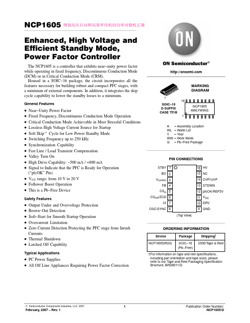
NCP1605Enhanced, High Voltage and Efficient Standby Mode, Power Factor ControllerThe NCP1605 is a controller that exhibits near−unity power factor while operating in fixed frequency, Discontinuous Conduction Mode (DCM) or in Critical Conduction Mode (CRM).Housed in a SOIC−16 package, the circuit incorporates all the features necessary for building robust and compact PFC stages, with a minimum of external components. In addition, it integrates the skip cycle capability to lower the standby losses to a minimum.General Features•Near−Unity Power Factor•Fixed Frequency, Discontinuous Conduction Mode Operation •Critical Conduction Mode Achievable in Most Stressful Conditions •Lossless High V oltage Current Source for Startup•Soft Skip t Cycle for Low Power Standby Mode •Switching Frequency up to 250 kHz •Synchronization Capability•Fast Line / Load Transient Compensation•V alley Turn On•High Drive Capability: −500 mA / +800 mA•Signal to Indicate that the PFC is Ready for Operation (“pfcOK” Pin)•V CC range: from 10 V to 20 V•Follower Boost Operation•This is a Pb−Free DeviceSafety Features•Output Under and Overvoltage Protection•Brown−Out Detection•Soft−Start for Smooth Startup Operation•Overcurrent Limitation•Zero Current Detection Protecting the PFC stage from Inrush Currents•Thermal Shutdown•Latched Off CapabilityTypical Applications•PC Power Supplies•All Off Line Appliances Requiring Power Factor CorrectionSOIC−16D SUFFIXCASE 751BDevice Package Shipping†ORDERING INFORMATIONMARKINGDIAGRAMA= Assembly LocationWL= Wafer LotY= YearWW= Work WeekG= Pb−Free PackageNCP1605AWLYWWG(T op View)CS inSTBYBOV controlFBCS out/ZCDCtOSC/SYNCHVNCpfcOK/REF5VV CCGNDOVP/UVPDRVSTDWNPIN CONNECTIONS†For information on tape and reel specifications, including part orientation and tape sizes, please refer to our T ape and Reel Packaging Specification Brochure, BRD8011/D.1NCP1605DR2G SOIC−16(Pb−Free)2500/T ape & Reel16增强高压启动和高效率待机的功率因数校正器Figure 1.MAXIMUM RATINGSPin Rating Symbol Value Unit 10Power Supply Input V CC−0.3, +20V 10The maximum transient voltage (Note 1)V CC−0.3, +25V 1, 2, 4, 6, 7, 8,13 and 14Input Voltage V I−0.3, +9V3V CONTROL Pin V CONTROL−0.3, V CONTROL MAX(Note 1)V 16High Voltage Pin HV−0.3, +500V Power Dissipation and Thermal Characteristics:Maximum Power Dissipation @ T A = 70°C Thermal Resistance Junction−to−AirP DR q JA550145mW°C/WOperating Junction T emperature Range T J−40, +125°CMaximum Junction T emperature T Jmax150°CStorage T emperature Range T Smax−65 to 150°°CLead T emperature (Soldering, 10 s)T Lmax300°C Stresses exceeding Maximum Ratings may damage the device. Maximum Ratings are stress ratings only. Functional operation above the Recommended Operating Conditions is not implied. Extended exposure to stresses above the Recommended Operating Conditions may affect device reliability.1.“V CONTROL MAX” is the pin clamp voltagePIN FUNCTION DESCRIPTIONPin NumberNameFunction1STBY An external signal (typically, a portion of the feedback signal of the downstream converter or a filtered portion of the SMPS drive pulses) should be applied to Pin 1. When the Pin 3 voltage goes below 300 mV, the circuit enters a burst mode operation where the bulk voltage varies between the regulation voltage and 95.5% of this level.2Brown−Out /InhibitionApply a portion of the averaged input voltage to detect brown−out conditions. If V Pin2 is lower than 0.5 V, the circuit stops pulsing until V Pin2 exceeds 1 V (0.5 V hysteresis).Ground Pin 6 to disable the part.3V CONTROL /Soft−Start The error amplifier output is available on this Pin. The capacitor connected between this pin and ground adjusts the regulation loop bandwidth that is typically set below 20 Hz to achieve high Power Factor ratios.Pin 3 is grounded when the circuit is off so that when it starts operation, the power increases slowly (soft−start).4Feedback This pin receives a portion of the pre−converter output voltage. This information is used for theregulation and the “output low” detection (V OUT L) that drastically speed up the loop response when the output voltage drops below 95.5% of the wished level.5Current SenseInput This pin monitors a negative voltage proportional to the coil current. This signal is sensed to limit the maximum coil current and detect the core reset (coil demagnetization).6Current SenseOutput This pin sources the Pin 5 current. Place a resistor between Pin 6 and ground to build the voltageproportional to the coil current and detect the core reset. The impedance between Pin 6 and ground should not exceed 3 times that of the Pin 5 to ground. You can further apply the voltage from anauxiliary winding to improve the valley detection of the MOSFET drain source voltage.7Ct(Ramp)The circuit controls the power switch on−time by comparing the Pin 7 ramp to an internal voltage(“V ton ”) derived from the regulation block and the sensed “dcycle” (relative duration of the current cycle over the corresponding switching period).Pin 7 sources a current proportional to the squared output voltage to allow the Follower Boost operation(optional) where the PFC output voltage stabilizes at a level that varies linearly versus the ac line amplitude. This technique reduces the difference between the output and input voltages, to optimize the boost efficiency and minimize the size and cost of the PFC stage8Oscillator /synchronization Connect a capacitor or apply a synchronization signal to this pin to set the switching frequency. If the coil current cycle is longer than the selected switching period, the circuit delays the next cycle until the core is reset. Hence, the PFC stage can operate in CRM in the most stressful conditions.9GNDConnect this pin to the pre−converter ground.10Drive The high current capability of the totem pole gate drive (+0.5/−0.8 A) makes it suitable to effectively drive high gate charge power MOSFET s.11V CCThis pin is the positive supply of the IC. The circuit starts to operate when V CC exceeds 15 V and turns off when V CC goes below 9 V (typical values). After startup, the operating range is 10 V up to 20 V.12PfcOK / REF5V The Pin 12 voltage is high (5 V) when the PFC stage is in a normal, steady state situation and low otherwise. This signal serves to “inform” the downstream converter that the PFC stage is ready and that hence, it can start operation.13STDWNApply a voltage higher than 2.5 V on Pin 13 to permanently shutdown the circuit. This pin can be used to monitor the voltage across a thermistor in order to protect the application from an excessive heating and/or to detect an overvoltage condition.T o resume operation, it is necessary to decrease the circuit V CC below V CC RST (4 V typically) by for instance, unplugging the PFC stage and replugging it after V CC is discharged.14OVP / UVPThe circuit turns off when V Pin14 goes below 480 mV (UVP) and disables the drive as long as the pin voltage exceeds 2.5 V (OVP).15NC Creepage distance.16HVConnect Pin 16 to the bulk capacitor. The internal startup current source placed between Pin 16 and the V CC terminal, charges the V CC capacitor at startup.一个外部信号乮代表性的如后极的降压变化器的反馈信号丆或者经过过滤的后极SMPS 驱动脉冲)加在PIN1•C 当PIN1电压低于300mV,电路进入burst 模式丆大电容电压在额定值的95.5--100%间变动。
MX25L3205D中文资料

16M-BIT [x 1 / x 2] CMOS SERIAL FLASH 32M-BIT [x 1 / x 2] CMOS SERIAL FLASH 64M-BIT [x 1 / x 2] CMOS SERIAL FLASHFEATURESGENERAL• Serial Peripheral Interface compatible -- Mode 0 and Mode 3• 16M:16,777,216 x 1 bit structure or 8,388,608 x 2 bits (two I/O read mode) structure 32M:33,554,432 x 1 bit structure or 16,772,216 x 2 bits (two I/O read mode) structure 64M:67,108,864 x 1 bit structure or 33,554,432 x 2 bits (two I/O read mode) structure • 512 Equal Sectors with 4K byte each (16Mb)1024 Equal Sectors with 4K byte each (32Mb)2048 Equal Sectors with 4K byte each (64Mb)- Any Sector can be erased individually•32 Equal Blocks with 64K byte each (16Mb)64 Equal Blocks with 64K byte each (32Mb)128 Equal Blocks with 64K byte each (64Mb)- Any Block can be erased individually • Single Power Supply Operation- 2.7 to 3.6 volt for read, erase, and program operations • Latch-up protected to 100mA from -1V to Vcc +1V • Low Vcc write inhibit is from 1.5V to 2.5VPERFORMANCE • High Performance- Fast access time: 86MHz serial clock (15pF + 1TTL Load) and 66MHz serial clock (30pF + 1TTL Load)- Serial clock of two I/O read mode : 50MHz (15pF + TTL Load), which is equivalent to 100MHz - Fast program time: 1.4ms(typ.) and 5ms(max.)/page (256-byte per page)- Byte program time: 9us (typical)- Continuously program mode (automatically increase address under word program mode)- Fast erase time: 60ms(typ.) /sector (4K-byte per sector) ; 0.7s(typ.) /block (64K-byte per block); 14s(typ.) /chip for 16Mb, 25s(typ.) for 32Mb, and 50s(typ.) for 64Mb • Low Power Consumption- Low active read current: 25mA(max.) at 86MHz, 20mA(max.) at 66MHz and 10mA(max.) at 33MHz - Low active programming current: 20mA (max.)- Low active erase current: 20mA (max.)- Low standby current: 20uA (max.)- Deep power-down mode 1uA (typical)• Typical 100,000 erase/program cyclesSOFTWARE FEATURES • Input Data Format- 1-byte Command code •Advanced Security Features - Block lock protectionThe BP0-BP3 status bit defines the size of the area to be software protection against program and erase instructions - Additional 512-bit secured OTP for unique identifier • Auto Erase and Auto Program Algorithm- Automatically erases and verifies data at selected sector- Automatically programs and verifies data at selected page by an internal algorithm that automatically times the program pulse widths (Any page to be programed should have page in the erased state first)MX25L1605D MX25L3205D MX25L6405D元器件交易网•Status Register Feature•Electronic Identification- JEDEC 1-byte manufacturer ID and 2-byte device ID- RES command for 1-byte Device ID- Both REMS and REMS2 commands for 1-byte manufacturer ID and 1-byte device IDHARDWARE FEATURES• SCLK Input- Serial clock input• SI Input- Serial Data Input• SO Output- Serial Data Output• WP#/ACC pin- Hardware write protection and program/erase acceleration• HOLD# pin- pause the chip without diselecting the chip• PACKAGE- 16-pin SOP (300mil)- 8-land WSON (8x6mm or 6x5mm)- 8-pin SOP (200mil, 150mil)- 8-pin PDIP (300mil)- 8-land USON (4x4mm)- All Pb-free devices are RoHS CompliantALTERNATIVE• Security Serial Flash (MX25L1615D/MX25L3215D/MX25L6415D) may provides additional protection features for op-tion. The datasheet is provided under NDA.GENERAL DESCRIPTIONThe MX25L1605D are 16,777,216 bit serial Flash memory, which is configured as 2,097,152 x 8 internally. When it is in two I/O read mode, the structure becomes 8,388,608 bits x 2. The MX25L3205D are 33,554,432 bit serial Flash memory, which is configured as 4,194,304 x 8 internally. When it is in two I/O read mode, the structure becomes 16,772,216 bits x 2. The MX25L6405D are 67,108,864 bit serial Flash memory, which is configured as 8,388,608 x 8 internally. When it is in two I/O read mode, the structure becomes 33,554,432 bits x 2. (please refer to the "Two I/O Read mode" section). The MX25L1605D/3205D/6405D feature a serial peripheral interface and software protocol allowing operation on a simple 3-wire bus. The three bus signals are a clock input (SCLK), a serial data input (SI), and a serial data output (SO). Serial access to the device is enabled by CS# input.When it is in two I/O read mode, the SI pin and SO pin become SIO0 pin and SIO1 pin for address/dummy bits input and data output.The MX25L1605D/3205D/6405D provides sequential read operation on whole chip.After program/erase command is issued, auto program/ erase algorithms which program/ erase and verify the specified page or sector/block locations will be executed. Program command is executed on byte basis, or page (256 bytes) basis, or word basis for Continuously program mode, and erase command is executes on sector (4K-byte), or block (64K-byte), or whole chip basis.To provide user with ease of interface, a status register is included to indicate the status of the chip. The status read command can be issued to detect completion status of a program or erase operation via WIP bit.Advanced security features enhance the protection and security functions, please see security features section for more details.When the device is not in operation and CS# is high, it is put in standby mode and draws less than 20uA DC current. The MX25L1605D/3205D/6405D utilizes MXIC's proprietary memory cell, which reliably stores memory contents even after typical 100,000 program and erase cycles.Table 1. Additional Feature ComparisonPIN CONFIGURATIONSSYMBOL DESCRIPTION CS#Chip SelectSI/SIO0Serial Data Input (for 1 x I/O)/ Serial Data Input & Output (for 2xI/O read mode)SO/SIO1Serial Data Output (for 1 x I/O)/ Serial Data Input & Output (for 2xI/O read mode)SCLK Clock InputWP#/ACCWrite protection: connect to GND ;9.5~10.5V for program/eraseacceleration: connect to 9.5~10.5V HOLD#Hold, to pause the device without deselecting the device VCC + 3.3V Power Supply GNDGroundPIN DESCRIPTION16-PIN SOP (300mil)8-LAND WSON (8x6mm, 6x5mm), USON (4x4mm)8-PIN SOP (200mil, 150mil)PACKAGE OPTIONS16M 32M 64M150mil 8-SOP V 200mil 8-SOP V V 300mil 16-SOP V V V300mil 8-PDIP V V 6x5mm WSON V V 8x6mm WSON V4x4mm USONVV12345678HOLD#VCC NC NC NC NC CS#SO/SIO1161514131211109SCLK SI/SIO0NC NC NC NC GND WP#/ACCCS#SO/SIO1WP#/ACCGND VCC HOLD#SCLK SI/SIO0CS#SO/SIO1WP#/ACC GND VCC HOLD#SCLK SI/SIO01234CS#SO/SIO1WP#/ACC GND 8765VCC HOLD#SCLK SI/SIO08-PIN PDIP (300mil)BLOCK DIAGRAMDATA PROTECTIONThe MX25L1605D/3205D/6405D is designed to offer protection against accidental erasure or programming caused by spurious system level signals that may exist during power transition. During power up the device automatically resets the state machine in the Read mode. In addition, with its control register architecture, alteration of the memory contents only occurs after successful completion of specific command sequences. The device also incorporates several features to prevent inadvertent write cycles resulting from VCC power-up and power-down transition or system noise.•Power-on reset and tPUW: to avoid sudden power switch by system power supply transition, the power-on reset and tPUW (internal timer) may protect the Flash.• Valid command length checking: The command length will be checked whether it is at byte base and completed on byte boundary.• Write Enable (WREN) command: WREN command is required to set the Write Enable Latch bit (WEL) before other command to change data. The WEL bit will return to reset stage under following situation:- Power-up- Write Disable (WRDI) command completion- Write Status Register (WRSR) command completion- Page Program (PP) command completion- Continuously Program mode (CP) instruction completion- Sector Erase (SE) command completion- Block Erase (BE) command completion- Chip Erase (CE) command completion- Write Read-lock Bit (WRLB) instruction completion•Deep Power Down Mode: By entering deep power down mode, the flash device also is under protected from writing all commands except Release from deep power down mode command (RDP) and Read Electronic Signature command (RES).•Advanced Security Features: there are some protection and securuity features which protect content from inadvertent write and hostile access.I. Block lock protection- The Software Protected Mode (SPM) use (BP3, BP2, BP1, BP0) bits to allow part of memory to be protected as read only. The proected area definition is shown as table of "Protected Area Sizes", the protected areas are more flexible which may protect various area by setting value of BP0-BP3 bits.Please refer to table of "protected area sizes".- The Hardware Proteced Mode (HPM) use WP#/ACC to protect the (BP3, BP2, BP1, BP0) bits and SRWD bit.Table 2. Protected Area SizesII. Additional 512-bit secured OTP for unique identifier: to provide 512-bit one-time program area for setting device unique serial number - Which may be set by factory or system customer. Please refer to table 3. 512-bit secured OTP definition.- Security register bit 0 indicates whether the chip is locked by factory or not.- To program the 512-bit secured OTP by entering 512-bit secured OTP mode (with ENSO command), and going through normal program procedure, and then exiting 512-bit secured OTP mode by writing EXSO command.- Customer may lock-down the customer lockable secured OTP by writing WRSCUR(write security register) command to set customer lock-down bit1 as "1". Please refer to table of "security register definition" for security register bit definition and table of "512-bit secured OTP definition" for address range definition.- Note: Once lock-down whatever by factory or customer, it cannot be changed any more. While in 512-bit secured OTP mode, array access is not allowed.Table 3. 512-bit Secured OTP DefinitionAddress range Size Standard Customer LockFactory Lockxxxx00~xxxx0F128-bit ESN (electrical serial number)Determined by customer xxxx10~xxxx3F384-bit N/AHOLD FEATURESHOLD# pin signal goes low to hold any serial communications with the device. The HOLD feature will not stop the operation of write status register, programming, or erasing in progress.The operation of HOLD requires Chip Select(CS#) keeping low and starts on falling edge of HOLD# pin signal while Serial Clock (SCLK) signal is being low (if Serial Clock signal is not being low, HOLD operation will not start until Serial Clock signal being low). The HOLD condition ends on the rising edge of HOLD# pin signal while Serial Clock(SCLK) signal is being low( if Serial Clock signal is not being low, HOLD operation will not end until Serial Clock being low), see Figure 1. Figure 1. Hold Condition OperationThe Serial Data Output (SO) is high impedance, both Serial Data Input (SI) and Serial Clock (SCLK) are don't care during the HOLD operation. If Chip Select (CS#) drives high during HOLD operation, it will reset the internal logic of the device. To re-start communication with chip, the HOLD# must be at high and CS# must be at low.PROGRAM/ERASE ACCELERATIONTo activate the program/erase acceleration function requires ACC pin connecting to 9.5~10.5V voltage (see Figure 2), and then to be followed by the normal program/erase process. By utilizing the program/erase acceleration operation, the performances are improved as shown on table of "ERASE AND PROGRAM PERFORMACE".After power-up ready, it should wait 10ms at least to apply VHH(9.5~10.5V) on the WP#/ACC pin.Figure 2. ACCELERATED PROGRAM TIMING DIAGRAMNote: tVHH (VHH Rise and Fall Time) min. 250nsTable 4. COMMAND DEFINITIONCOMMAND (byte)WREN (writeenable)WRDI (write disable)RDID (read identification )RDSR (read statusregister)WRSR(write status register)READ (read data)FAST READ(fast read data)2READ (2x I/O read command)note1SE (sector erase)1st byte 06 (hex)04 (hex)9F (hex)05 (hex)01 (hex)03 (hex)0B (hex)BB (hex)20 (hex)2nd byte AD1AD1ADD(2)AD13rd byte AD2AD2ADD(2) &Dummy(2)AD24th byte AD3AD3AD35th byte Actionsets the (WEL)write enable latch bit resets the (WEL)write enable latch bitoutputs JEDEC ID:1-byte manufactur er ID & 2-byte device IDto read out the values of the status register to writenew values to the statusregister n bytes read out until CS#goes high n bytes read out until CS#goes high n bytes read out by 2 x I/O until CS#goes high to erase the selectedsector Note 1: The count base is 4-bit for ADD(2) and Dummy(2) because of 2 x I/O. And the MSB is on SI/SIO0 which is different from 1 x I/O conditionCOMMAND (byte)BE (block erase)CE (chip erase)PP (Page program)CP (Continuo-usly program mode)DP (Deep powerdown)RDP (Release from deep power down)RES (read electronic ID)REMS(read electronic manufactu-rer &device ID)REMS2(read ID for 2x I/O mode)1st byte D8 (hex)60 or C7(hex)02 (hex)AD (hex)B9 (hex)AB (hex)AB (hex)90 (hex)EF (hex)2nd byte AD1AD1AD1x x x 3rd byte AD2AD2AD2x x x 4th byte AD3AD3AD3x ADD(note 2)ADD(note2)5th byteAction to erase theselected block to erase whole chip to program the selected page continously program wholechip, theaddress is automatica lly increaseentersdeep power down moderelease from deep power down mode to read out 1-byte device ID outout the manufactu-rer ID &device ID output the manufactu-rer ID &device ID Note 2: ADD=00H will output the manufacturer ID first and ADD=01H will output device ID first Note 3: It is not recommoded to adopt any other code not in the command definition table, which will potentially enter the hidden mode.COMMAND (byte)ENSO (enter secured OTP)EXSO (exit secured OTP)RDSCUR (read security register)WRSCUR (write security register)ESRY (enable SO to output RY/BY#)DSRY (disable SO to output RY/BY#)1st byte B1 (hex)C1 (hex)2B (hex)2F (hex)70 (hex)80 (hex)2nd byte 3rd byte 4th byte 5th byte Actionto enter the 512-bit secured OTP mode to exit the 512-bit secured OTP mode to read value of security registerto set the lock-down bit as "1"(once lock-down,cannot be updated)to enable SO to output RY/BY#during CP mode to disable SO to output RY/BY#during CP modeDummyTable 5-1. Memory Organization (16Mb)Table 5-2. Memory Organization (32Mb)Table 5-3. Memory Organization (64Mb)DEVICE OPERATION1.Before a command is issued, status register should be checked to ensure device is ready for the intended operation.2.When incorrect command is inputted to this LSI, this LSI becomes standby mode and keeps the standby mode until next CS# falling edge. In standby mode, SO pin of this LSI should be High-Z.3.When correct command is inputted to this LSI, this LSI becomes active mode and keeps the active mode until next CS# rising edge.4.Input data is latched on the rising edge of Serial Clock(SCLK) and data shifts out on the falling edge of SCLK. The difference of Serial mode 0 and mode 3 is shown as Figure 3.Figure 3. Serial Modes Supported5.For the following instructions: RDID, RDSR, RDSCUR, READ, FAST_READ, 2READ, RES, REMS and REMS2 the shifted-in instruction sequence is followed by a data-out sequence. After any bit of data being shifted out, the CS# can be high. For the following instructions: WREN, WRDI, WRSR, SE, BE, CE, PP, CP, RDP, DP, ENSO, EXSO,and WRSCUR, the CS# must go high exactly at the byte boundary; otherwise, the instruction will be rejected and not executed.6.During the progress of Write Status Register, Program, Erase operation, to access the memory array is neglected and not affect the current operation of Write Status Register, Program, Erase.Note:CPOL indicates clock polarity of Serial master, CPOL=1 for SCLK high while idle, CPOL=0 for SCLK low while not transmitting. CPHA indicates clock phase. The combination of CPOL bit and CPHA bit decides which Serial mode is supported.SCLKMSBCPHASI 01CPOL 0(Serial mode 0)(Serial mode 3)1SO SCLKMSBCOMMAND DESCRIPTION(1) Write Enable (WREN)The Write Enable (WREN) instruction is for setting Write Enable Latch (WEL) bit. For those instructions like PP, CP, SE, BE, CE, and WRSR, which are intended to change the device content, should be set every time after the WREN instruction setting the WEL bit.The sequence of issuing WREN instruction is: CS# goes low-> sending WREN instruction code-> CS# goes high. (see Figure 12)(2) Write Disable (WRDI)The Write Disable (WRDI) instruction is for resetting Write Enable Latch (WEL) bit.The sequence of issuing WRDI instruction is: CS# goes low-> sending WRDI instruction code-> CS# goes high. (see Figure 13)The WEL bit is reset by following situations:- Power-up- Write Disable (WRDI) instruction completion- Write Status Register (WRSR) instruction completion- Page Program (PP) instruction completion- Sector Erase (SE) instruction completion- Block Erase (BE) instruction completion- Chip Erase (CE) instruction completion- Continuously program mode (CP) instruction completion(3) Read Identification (RDID)The RDID instruction is for reading the manufacturer ID of 1-byte and followed by Device ID of 2-byte. The MXIC Manufacturer ID is C2(hex), the memory type ID is 20(hex) as the first-byte device ID, and the individual device ID of second-byte ID are listed as table of "ID Definitions".The sequence of issuing RDID instruction is: CS# goes low-> sending RDID instruction code -> 24-bits ID data out on SO -> to end RDID operation can use CS# to high at any time during data out. (see Figure. 14)While Program/Erase operation is in progress, it will not decode the RDID instruction, so there's no effect on the cycle of program/erase operation which is currently in progress. When CS# goes high, the device is at standby stage.(4) Read Status Register (RDSR)The RDSR instruction is for reading Status Register Bits. The Read Status Register can be read at any time (even in program/erase/write status register condition) and continuously. It is recommended to check the Write in Progress (WIP) bit before sending a new instruction when a program, erase, or write status register operation is in progress.The sequence of issuing RDSR instruction is: CS# goes low-> sending RDSR instruction code-> Status Register data out on SO (see Figure. 15)The definition of the status register bits is as below:WIP bit. The Write in Progress (WIP) bit, a volatile bit, indicates whether the device is busy in program/erase/write status register progress. When WIP bit sets to 1, which means the device is busy in program/erase/write status register progress. When WIP bit sets to 0, which means the device is not in progress of program/erase/write status register cycle.WEL bit. The Write Enable Latch (WEL) bit, a volatile bit, indicates whether the device is set to internal write enable latch. When WEL bit sets to 1, which means the internal write enable latch is set, the device can accept program/erase/write status register instruction. When WEL bit sets to 0, which means no internal write enable latch; the device will not accept program/erase/write status register instruction. The program/erase command will be ignored and not affect value of WEL bit if it is applied to a protected memory area.BP3, BP2, BP1, BP0 bits. The Block Protect (BP3, BP2, BP1, BP0) bits, non-volatile bits, indicate the protected area(as defined in table 1) of the device to against the program/erase instruction without hardware protection mode being set. To write the Block Protect (BP3, BP2, BP1, BP0) bits requires the Write Status Register (WRSR) instruction to be executed. Those bits define the protected area of the memory to against Page Program (PP), Sector Erase (SE), Block Erase (BE) and Chip Erase(CE) instructions (only if all Block Protect bits set to 0, the CE instruction can be executed).Continuously Program Mode( CP mode) bit. The Continuously Program Mode bit indicates the status of CP mode, "0" indicates not in CP mode; "1" indicates in CP mode.SRWD bit. The Status Register Write Disable (SRWD) bit, non-volatile bit, is operated together with Write Protection (WP#/ ACC) pin for providing hardware protection mode. The hardware protection mode requires SRWD sets to 1 and WP#/ACC pin signal is low stage. In the hardware protection mode, the Write Status Register (WRSR) instruction is no longer accepted for execution and the SRWD bit and Block Protect bits (BP3, BP2, BP1, BP0) are read only.Status Registernote1: see the table "Protected Area Sizes"(5) Write Status Register (WRSR)The WRSR instruction is for changing the values of Status Register Bits. Before sending WRSR instruction, the Write Enable (WREN) instruction must be decoded and executed to set the Write Enable Latch (WEL) bit in advance. The WRSR instruction can change the value of Block Protect (BP3, BP2, BP1, BP0) bits to define the protected area of memory (as shown in table 1). The WRSR also can set or reset the Status Register Write Disable (SRWD) bit in accordance with Write Protection (WP#/ACC) pin signal. The WRSR instruction cannot be executed once the Hardware Protected Mode (HPM)is entered.The sequence of issuing WRSR instruction is: CS# goes low-> sending WRSR instruction code-> Status Register data on SI-> CS# goes high. (see Figure 16)The WRSR instruction has no effect on b6, b1, b0 of the status register.The CS# must go high exactly at the byte boundary; otherwise, the instruction will be rejected and not executed. The self-timed Write Status Register cycle time (tW) is initiated as soon as Chip Select (CS#) goes high. The Write in Progress (WIP) bit still can be check out during the Write Status Register cycle is in progress. The WIP sets 1 during the tW timing,and sets 0 when Write Status Register Cycle is completed, and the Write Enable Latch (WEL) bit is reset.Table 6. Protection ModesNote:1. As defined by the values in the Block Protect (BP3, BP2, BP1, BP0) bits of the Status Register, as shown in Table 1.As the above table showing, the summary of the Software Protected Mode (SPM) and Hardware Protected Mode (HPM).Software Protected Mode (SPM):-When SRWD bit=0, no matter WP#/ACC is low or high, the WREN instruction may set the WEL bit and can changethe values of SRWD, BP3, BP2, BP1, BP0. The protected area, which is defined by BP3, BP2, BP1, BP0, is at software protected mode (SPM).-When SRWD bit=1 and WP#/ACC is high, the WREN instruction may set the WEL bit can change the values of SRWD,BP3, BP2, BP1, BP0. The protected area, which is defined by BP3, BP2, BP1, BP0, is at software protected mode (SPM)ModeStatus register condition Software protection mode(SPM)Status register can be written in (WEL bit is set to "1") and the SRWD, BP0-BP3bits can be changedWP# and SRWD bit status MemoryWP#=1 and SRWD bit=0, or WP#=0 and SRWD bit=0, or WP#=1 and SRWD=1The protected area cannot be program or erase.The protected area cannot be program or erase.WP#=0, SRWD bit=1The SRWD, BP0-BP3 ofstatus register bits cannot be changedHardware protection mode (HPM)Note: If SRWD bit=1 but WP#/ACC is low, it is impossible to write the Status Register even if the WEL bit has previously been set. It is rejected to write the Status Register and not be executed.Hardware Protected Mode (HPM):-When SRWD bit=1, and then WP#/ACC is low (or WP#/ACC is low before SRWD bit=1), it enters the hardware protected mode (HPM). The data of the protected area is protected by software protected mode by BP3, BP2, BP1, BP0 and hardware protected mode by the WP#/ACC to against data modification.Note: to exit the hardware protected mode requires WP#/ACC driving high once the hardware protected mode is entered. If the WP#/ACC pin is permanently connected to high, the hardware protected mode can never be entered; only can use software protected mode via BP3, BP2, BP1, BP0.(6) Read Data Bytes (READ)The read instruction is for reading data out. The address is latched on rising edge of SCLK, and data shifts out on the falling edge of SCLK at a maximum frequency fR. The first address byte can be at any location. The address is automatically increased to the next higher address after each byte data is shifted out, so the whole memory can be read out at a single READ instruction. The address counter rolls over to 0 when the highest address has been reached.The sequence of issuing READ instruction is: CS# goes low-> sending READ instruction code-> 3-byte address on SI -> data out on SO-> to end READ operation can use CS# to high at any time during data out. (see Figure. 17)(7) Read Data Bytes at Higher Speed (FAST_READ)The FAST_READ instruction is for quickly reading data out. The address is latched on rising edge of SCLK, and data of each bit shifts out on the falling edge of SCLK at a maximum frequency fC. The first address byte can be at any location. The address is automatically increased to the next higher address after each byte data is shifted out, so the whole memory can be read out at a single FAST_READ instruction. The address counter rolls over to 0 when the highest address has been reached.The sequence of issuing FAST_READ instruction is: CS# goes low-> sending FAST_READ instruction code-> 3-byte address on SI-> 1-dummy byte address on SI->data out on SO-> to end FAST_READ operation can use CS# to high at any time during data out. (see Figure. 18)While Program/Erase/Write Status Register cycle is in progress, FAST_READ instruction is rejected without any impact on the Program/Erase/Write Status Register current cycle.(8) 2 x I/O Read Mode (2READ)The 2READ instruction enable double throughput of Serial Flash in read mode. The address is latched on rising edge of SCLK, and data of every two bits(interleave on 2 I/O pins) shift out on the falling edge of SCLK at a maximum frequency fT. The first address byte can be at any location. The address is automatically increased to the next higher address after each byte data is shifted out, so the whole memory can be read out at a single 2READ instruction. The address counter rolls over to 0 when the highest address has been reached. Once writing 2READ instruction, the following address/dummy/ data out will perform as 2-bit instead of previous 1-bit.The sequence of issuing 2READ instruction is: CS# goes low→ sending 2READ instruction→ 24-bit address interleave on SIO1 & SIO0→ 8-bit dummy interleave on SIO1 & SIO0→ data out interleave on SIO1 & SIO0→ to end 2READ operation can use CS# to high at any time during data out (see Figure of 2 x I/O Read Mode Timing Waveform)While Program/Erase/Write Status Register cycle is in progress, 2READ instruction is rejected without any impact on the Program/Erase/Write Status Register current cycle.The 2 I/O only perform read operation. Program/Erase /Read ID/Read status/Read ID....operation do not support 2 I/O throughputs.(9) Sector Erase (SE)The Sector Erase (SE) instruction is for erasing the data of the chosen sector to be "1". The instruction is used for any 4K-byte sector. A Write Enable (WREN) instruction must execute to set the Write Enable Latch (WEL) bit before sending the Sector Erase (SE). Any address of the sector (see table 3) is a valid address for Sector Erase (SE) instruction. The CS# must go high exactly at the byte boundary (the latest eighth of address byte been latched-in); otherwise, the instruction will be rejected and not executed.Address bits [Am-A12] (Am is the most significant address) select the sector address.The sequence of issuing SE instruction is: CS# goes low -> sending SE instruction code-> 3-byte address on SI -> CS# goes high. (see Figure 22)The self-timed Sector Erase Cycle time (tSE) is initiated as soon as Chip Select (CS#) goes high. The Write in Progress (WIP) bit still can be check out during the Sector Erase cycle is in progress. The WIP sets 1 during the tSE timing, and sets 0 when Sector Erase Cycle is completed, and the Write Enable Latch (WEL) bit is reset. If the page is protected by BP3, BP2, BP1, BP0 bits, the Sector Erase (SE) instruction will not be executed on the page.(10) Block Erase (BE)The Block Erase (BE) instruction is for erasing the data of the chosen block to be "1". The instruction is used for 64K-byte sector erase operation. A Write Enable (WREN) instruction must execute to set the Write Enable Latch (WEL) bit before sending the Block Erase (BE). Any address of the block (see table 3) is a valid address for Block Erase (BE) instruction. The CS# must go high exactly at the byte boundary (the latest eighth of address byte been latched-in); otherwise, the instruction will be rejected and not executed.The sequence of issuing BE instruction is: CS# goes low -> sending BE instruction code-> 3-byte address on SI -> CS# goes high. (see Figure 23)The self-timed Block Erase Cycle time (tBE) is initiated as soon as Chip Select (CS#) goes high. The Write in Progress (WIP) bit still can be check out during the Sector Erase cycle is in progress. The WIP sets 1 during the tBE timing, and sets 0 when Sector Erase Cycle is completed, and the Write Enable Latch (WEL) bit is reset. If the page is protected by BP3, BP2, BP1, BP0 bits, the Block Erase (BE) instruction will not be executed on the page.(11) Chip Erase (CE)The Chip Erase (CE) instruction is for erasing the data of the whole chip to be "1". A Write Enable (WREN) instruction must execute to set the Write Enable Latch (WEL) bit before sending the Chip Erase (CE). Any address of the sector (see table 3) is a valid address for Chip Erase (CE) instruction. The CS# must go high exactly at the byte boundary( the latest eighth of address byte been latched-in); otherwise, the instruction will be rejected and not executed.The sequence of issuing CE instruction is: CS# goes low-> sending CE instruction code-> CS# goes high. (see Figure 24)。
SPI FLASH编程器简介
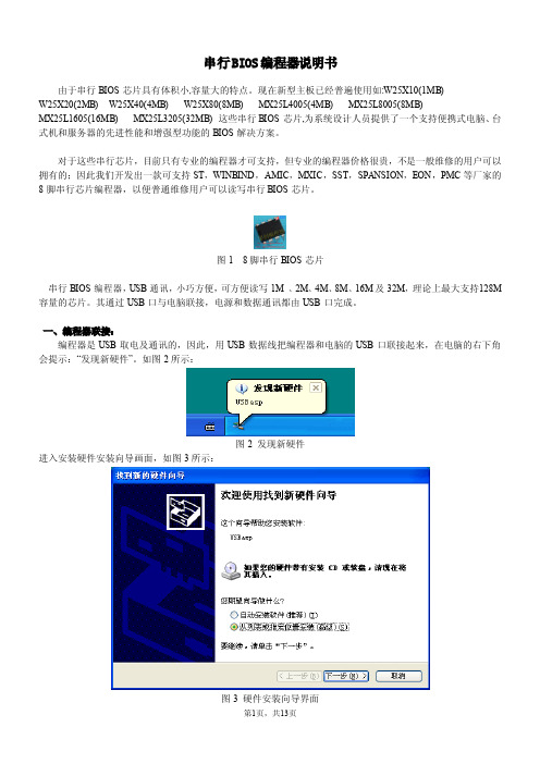
串行BIOS编程器说明书由于串行BIOS芯片具有体积小,容量大的特点。
现在新型主板已经普遍使用如:W25X10(1MB)W25X20(2MB)W25X40(4MB)W25X80(8MB)MX25L4005(4MB)MX25L8005(8MB)MX25L1605(16MB)MX25L3205(32MB)这些串行BIOS芯片,为系统设计人员提供了一个支持便携式电脑、台式机和服务器的先进性能和增强型功能的BIOS解决方案。
对于这些串行芯片,目前只有专业的编程器才可支持,但专业的编程器价格很贵,不是一般维修的用户可以拥有的;因此我们开发出一款可支持ST,WINBIND,AMIC,MXIC,SST,SPANSION,EON,PMC等厂家的8脚串行芯片编程器,以便普通维修用户可以读写串行BIOS芯片。
图18脚串行BIOS芯片串行BIOS编程器,USB通讯,小巧方便,可方便读写1M、2M、4M、8M、16M及32M,理论上最大支持128M 容量的芯片。
其通过USB口与电脑联接,电源和数据通讯都由USB口完成。
一、编程器联接:编程器是USB取电及通讯的,因此,用USB数据线把编程器和电脑的USB口联接起来,在电脑的右下角会提示:“发现新硬件”。
如图2所示:图2发现新硬件进入安装硬件安装向导画面,如图3所示:图3硬件安装向导界面选择“从列表或指定位置安装(高级)”,手动选择要安装USB驱动的位置在光盘:\usb_驱动目录中。
图4正在安装USB驱动图5USB驱动安装完毕最后,点击完成,USB驱动已正确识别并安装到电脑中,并且新硬件可以正常使用。
二、编程器软件安装:打开光盘,打开串行BIOS编程器软件文件夹,双击Setup.exe即开始安装串行BIOS编程器控制软件。
编程器USB驱动程序及控制软件正确安装后,按程序提示烧写芯片即可。
三、编程器使用:①主程序界面:USB驱动安装正确及USB数据线插好后,驱动程序的USB Status状态变成绿色;如果USB数据没有插好,则会变成红色。
L90多功能编程器使用说明书

L90多功能编程器使用说明L90多功能编程器,功能强大,支持最新的主板BIOS spi 25Xxxx 在线编程和高速烧写EPROM、EEPROM、FLASH和串行EEPROM 系列芯片,并且还直接支持PIC、MCS51、AVR单片机芯片;价格低,性价比高;既适合于电子和电脑爱好者使用,也适合于电子电脑维修人员和单片机开发人员使用。
一、特点:1、使用优质3M 32脚镀银锁紧座,夹具专用孔型18脚、8脚DIP插座,优质进口PLCC32座性能稳定可靠。
2、全新设计,使用USB和外接电源双接口供电,并使用25针PC并行打印口通讯,具有较高的写片速度。
3、采用WINDOWS下的图形界面,使用鼠标进行操作,支持Windows 95/98/ME/2000/XP系统。
4、支持最新810、815、845、848、865、875、915等等主板上使用的大容量FWH/LPC BIOS芯片,性能价格比高。
对于电脑爱好者维修者,可用来对电脑的各种板卡的BIOS芯片进行编程,修复被病毒破坏的主板BIOS芯片,对主板、显卡等的BIOS芯片进行升级以提升计算机性能等等。
5、主板上集成了93CXX、24CXX、25CXX PIC 16FXX、DIP32Z转PLCC32、FWH/LPC PLCC32适配器,支持51系列单片机的全系列型号,可用来进行单片机开发;支持最新的大容量程序芯片;支持12.5V、15V、21V、25V多种编程电压,直接支持3.3V及2.9V电压的芯片(即显卡的BIOS芯片如SST39VF512等)。
6、全新设计的硬件,让使用者更容易使用,控制程序工作界面友好,具有编程指示!对芯片的各种操作变得十分简单,无论是电子专业人员还是电脑爱好者、维修者都可轻松掌握。
7、软件随时更新,最新软件可免费获取。
注意:1、计算机的并口要在BIOS中设置为ECP或者ECP+EPP;2、多功能编程器使用的联机电缆是25针对25孔标准。
Usb-25系列BIOS编程器说明书由于串行BIOS芯片具有体积小,容量大的

Usb -25系列BIOS 编程器说明书由于串行BIOS 芯片具有体积小,容量大的特点。
现在新型主板已经普遍使用如:W25X10(1MB) W25X20(2MB) W25X40(4MB) W25X80(8MB) MX25L4005(4MB) MX25L8005(8MB)MX25L1605(16MB) MX25L3205(32MB) 这些串行BIOS 芯片,为系统设计人员提供了一个支持便携式电脑、台式机和服务器的先进性能和增强型功能的BIOS 解决方案。
对于这些串行芯片,目前只有专业的编程器才可支持,但专业的编程器价格很贵,不是一般维修的用户可以拥有的.为此应广大家电维修朋友的要求,我发了半年时间特开发几款专为读写bios芯片的编程器(支持A TMEL,MICROCHIP,ST,WINBOND,AMIC,MXIC,SST,SPANSION,EON,PMC等厂家8脚串行芯片),体积小巧(一个U盘体积大小),方便电脑主板及DVD等Bios升级注:目前市场上的USB isp flash编程器电路及程序处理不够,有99%的编程器包括百元以上的都存在隐患(插上USB,有些电脑根本无法识别,使用不稳定),我已在这方面作了很大改进,解决了这个隐患使编程更稳定,更安全,运行效率更高。
二.Usb BIOS 编程器使用说明:USB 通讯,小巧方便,可方便读写1M 、2M、4M、8M、16M 及32M,理论上最大支持128M容量的芯片。
其通过USB 口与电脑联接,电源和数据通讯都由USB 口完成。
1、编程器联接:编程器是USB 取电及通讯的,因此,用USB 数据线把编程器和电脑的USB 口联接起来,在电脑的右下角会提示:“发现新硬件”。
如图2 所示:选择“从列表或指定位置安装(高级)”,手动选择要安装USB 驱动的位置在如D:\usb_ 驱动目录中。
正在安装USB 驱动USB 驱动安装完毕最后,点击完成,USB 驱动已正确识别并安装到电脑中,并且新硬件可以正常使用。
MX25L8005PC-15G中文资料

• SO Output
- Serial Data Output
P/N: PM1237 1
REV. 2.2, OCT. 23, 2008
元器件交易网
MX25L8005
• WP# pin
- Hardware write protection
Clock Generator
Output Buffer
SO
P/N: PM1237
REV. 2.2, OCT. 23, 2008 3
元器件交易网
MX25L8005
DATA PROTECTION
The MX25L8005 are designed to offer protection against accidental erasure or programming caused by spurious system level signals that may exist during power transition. During power up the device automatically resets the state machine in the Read mode. In addition, with its control register architecture, alteration of the memory contents only occurs after successful completion of specific command sequences. The device also incorporates several features to prevent inadvertent write cycles resulting from VCC power-up and power-down transition or system noise.
MX25L6405D中文资料

16M-BIT [x 1 / x 2] CMOS SERIAL FLASH 32M-BIT [x 1 / x 2] CMOS SERIAL FLASH 64M-BIT [x 1 / x 2] CMOS SERIAL FLASHFEATURESGENERAL• Serial Peripheral Interface compatible -- Mode 0 and Mode 3• 16M:16,777,216 x 1 bit structure or 8,388,608 x 2 bits (two I/O read mode) structure 32M:33,554,432 x 1 bit structure or 16,772,216 x 2 bits (two I/O read mode) structure 64M:67,108,864 x 1 bit structure or 33,554,432 x 2 bits (two I/O read mode) structure • 512 Equal Sectors with 4K byte each (16Mb)1024 Equal Sectors with 4K byte each (32Mb)2048 Equal Sectors with 4K byte each (64Mb)- Any Sector can be erased individually•32 Equal Blocks with 64K byte each (16Mb)64 Equal Blocks with 64K byte each (32Mb)128 Equal Blocks with 64K byte each (64Mb)- Any Block can be erased individually • Single Power Supply Operation- 2.7 to 3.6 volt for read, erase, and program operations • Latch-up protected to 100mA from -1V to Vcc +1V • Low Vcc write inhibit is from 1.5V to 2.5VPERFORMANCE • High Performance- Fast access time: 86MHz serial clock (15pF + 1TTL Load) and 66MHz serial clock (30pF + 1TTL Load)- Serial clock of two I/O read mode : 50MHz (15pF + TTL Load), which is equivalent to 100MHz - Fast program time: 1.4ms(typ.) and 5ms(max.)/page (256-byte per page)- Byte program time: 9us (typical)- Continuously program mode (automatically increase address under word program mode)- Fast erase time: 60ms(typ.) /sector (4K-byte per sector) ; 0.7s(typ.) /block (64K-byte per block); 14s(typ.) /chip for 16Mb, 25s(typ.) for 32Mb, and 50s(typ.) for 64Mb • Low Power Consumption- Low active read current: 25mA(max.) at 86MHz, 20mA(max.) at 66MHz and 10mA(max.) at 33MHz - Low active programming current: 20mA (max.)- Low active erase current: 20mA (max.)- Low standby current: 20uA (max.)- Deep power-down mode 1uA (typical)• Typical 100,000 erase/program cyclesSOFTWARE FEATURES • Input Data Format- 1-byte Command code •Advanced Security Features - Block lock protectionThe BP0-BP3 status bit defines the size of the area to be software protection against program and erase instructions - Additional 512-bit secured OTP for unique identifier • Auto Erase and Auto Program Algorithm- Automatically erases and verifies data at selected sector- Automatically programs and verifies data at selected page by an internal algorithm that automatically times the program pulse widths (Any page to be programed should have page in the erased state first)MX25L1605D MX25L3205D MX25L6405D元器件交易网•Status Register Feature•Electronic Identification- JEDEC 1-byte manufacturer ID and 2-byte device ID- RES command for 1-byte Device ID- Both REMS and REMS2 commands for 1-byte manufacturer ID and 1-byte device IDHARDWARE FEATURES• SCLK Input- Serial clock input• SI Input- Serial Data Input• SO Output- Serial Data Output• WP#/ACC pin- Hardware write protection and program/erase acceleration• HOLD# pin- pause the chip without diselecting the chip• PACKAGE- 16-pin SOP (300mil)- 8-land WSON (8x6mm or 6x5mm)- 8-pin SOP (200mil, 150mil)- 8-pin PDIP (300mil)- 8-land USON (4x4mm)- All Pb-free devices are RoHS CompliantALTERNATIVE• Security Serial Flash (MX25L1615D/MX25L3215D/MX25L6415D) may provides additional protection features for op-tion. The datasheet is provided under NDA.GENERAL DESCRIPTIONThe MX25L1605D are 16,777,216 bit serial Flash memory, which is configured as 2,097,152 x 8 internally. When it is in two I/O read mode, the structure becomes 8,388,608 bits x 2. The MX25L3205D are 33,554,432 bit serial Flash memory, which is configured as 4,194,304 x 8 internally. When it is in two I/O read mode, the structure becomes 16,772,216 bits x 2. The MX25L6405D are 67,108,864 bit serial Flash memory, which is configured as 8,388,608 x 8 internally. When it is in two I/O read mode, the structure becomes 33,554,432 bits x 2. (please refer to the "Two I/O Read mode" section). The MX25L1605D/3205D/6405D feature a serial peripheral interface and software protocol allowing operation on a simple 3-wire bus. The three bus signals are a clock input (SCLK), a serial data input (SI), and a serial data output (SO). Serial access to the device is enabled by CS# input.When it is in two I/O read mode, the SI pin and SO pin become SIO0 pin and SIO1 pin for address/dummy bits input and data output.The MX25L1605D/3205D/6405D provides sequential read operation on whole chip.After program/erase command is issued, auto program/ erase algorithms which program/ erase and verify the specified page or sector/block locations will be executed. Program command is executed on byte basis, or page (256 bytes) basis, or word basis for Continuously program mode, and erase command is executes on sector (4K-byte), or block (64K-byte), or whole chip basis.To provide user with ease of interface, a status register is included to indicate the status of the chip. The status read command can be issued to detect completion status of a program or erase operation via WIP bit.Advanced security features enhance the protection and security functions, please see security features section for more details.When the device is not in operation and CS# is high, it is put in standby mode and draws less than 20uA DC current. The MX25L1605D/3205D/6405D utilizes MXIC's proprietary memory cell, which reliably stores memory contents even after typical 100,000 program and erase cycles.Table 1. Additional Feature ComparisonPIN CONFIGURATIONSSYMBOL DESCRIPTION CS#Chip SelectSI/SIO0Serial Data Input (for 1 x I/O)/ Serial Data Input & Output (for 2xI/O read mode)SO/SIO1Serial Data Output (for 1 x I/O)/ Serial Data Input & Output (for 2xI/O read mode)SCLK Clock InputWP#/ACCWrite protection: connect to GND ;9.5~10.5V for program/eraseacceleration: connect to 9.5~10.5V HOLD#Hold, to pause the device without deselecting the device VCC + 3.3V Power Supply GNDGroundPIN DESCRIPTION16-PIN SOP (300mil)8-LAND WSON (8x6mm, 6x5mm), USON (4x4mm)8-PIN SOP (200mil, 150mil)PACKAGE OPTIONS16M 32M 64M150mil 8-SOP V 200mil 8-SOP V V 300mil 16-SOP V V V300mil 8-PDIP V V 6x5mm WSON V V 8x6mm WSON V4x4mm USONVV12345678HOLD#VCC NC NC NC NC CS#SO/SIO1161514131211109SCLK SI/SIO0NC NC NC NC GND WP#/ACCCS#SO/SIO1WP#/ACCGND VCC HOLD#SCLK SI/SIO0CS#SO/SIO1WP#/ACC GND VCC HOLD#SCLK SI/SIO01234CS#SO/SIO1WP#/ACC GND 8765VCC HOLD#SCLK SI/SIO08-PIN PDIP (300mil)BLOCK DIAGRAMDATA PROTECTIONThe MX25L1605D/3205D/6405D is designed to offer protection against accidental erasure or programming caused by spurious system level signals that may exist during power transition. During power up the device automatically resets the state machine in the Read mode. In addition, with its control register architecture, alteration of the memory contents only occurs after successful completion of specific command sequences. The device also incorporates several features to prevent inadvertent write cycles resulting from VCC power-up and power-down transition or system noise.•Power-on reset and tPUW: to avoid sudden power switch by system power supply transition, the power-on reset and tPUW (internal timer) may protect the Flash.• Valid command length checking: The command length will be checked whether it is at byte base and completed on byte boundary.• Write Enable (WREN) command: WREN command is required to set the Write Enable Latch bit (WEL) before other command to change data. The WEL bit will return to reset stage under following situation:- Power-up- Write Disable (WRDI) command completion- Write Status Register (WRSR) command completion- Page Program (PP) command completion- Continuously Program mode (CP) instruction completion- Sector Erase (SE) command completion- Block Erase (BE) command completion- Chip Erase (CE) command completion- Write Read-lock Bit (WRLB) instruction completion•Deep Power Down Mode: By entering deep power down mode, the flash device also is under protected from writing all commands except Release from deep power down mode command (RDP) and Read Electronic Signature command (RES).•Advanced Security Features: there are some protection and securuity features which protect content from inadvertent write and hostile access.I. Block lock protection- The Software Protected Mode (SPM) use (BP3, BP2, BP1, BP0) bits to allow part of memory to be protected as read only. The proected area definition is shown as table of "Protected Area Sizes", the protected areas are more flexible which may protect various area by setting value of BP0-BP3 bits.Please refer to table of "protected area sizes".- The Hardware Proteced Mode (HPM) use WP#/ACC to protect the (BP3, BP2, BP1, BP0) bits and SRWD bit.Table 2. Protected Area SizesII. Additional 512-bit secured OTP for unique identifier: to provide 512-bit one-time program area for setting device unique serial number - Which may be set by factory or system customer. Please refer to table 3. 512-bit secured OTP definition.- Security register bit 0 indicates whether the chip is locked by factory or not.- To program the 512-bit secured OTP by entering 512-bit secured OTP mode (with ENSO command), and going through normal program procedure, and then exiting 512-bit secured OTP mode by writing EXSO command.- Customer may lock-down the customer lockable secured OTP by writing WRSCUR(write security register) command to set customer lock-down bit1 as "1". Please refer to table of "security register definition" for security register bit definition and table of "512-bit secured OTP definition" for address range definition.- Note: Once lock-down whatever by factory or customer, it cannot be changed any more. While in 512-bit secured OTP mode, array access is not allowed.Table 3. 512-bit Secured OTP DefinitionAddress range Size Standard Customer LockFactory Lockxxxx00~xxxx0F128-bit ESN (electrical serial number)Determined by customer xxxx10~xxxx3F384-bit N/AHOLD FEATURESHOLD# pin signal goes low to hold any serial communications with the device. The HOLD feature will not stop the operation of write status register, programming, or erasing in progress.The operation of HOLD requires Chip Select(CS#) keeping low and starts on falling edge of HOLD# pin signal while Serial Clock (SCLK) signal is being low (if Serial Clock signal is not being low, HOLD operation will not start until Serial Clock signal being low). The HOLD condition ends on the rising edge of HOLD# pin signal while Serial Clock(SCLK) signal is being low( if Serial Clock signal is not being low, HOLD operation will not end until Serial Clock being low), see Figure 1. Figure 1. Hold Condition OperationThe Serial Data Output (SO) is high impedance, both Serial Data Input (SI) and Serial Clock (SCLK) are don't care during the HOLD operation. If Chip Select (CS#) drives high during HOLD operation, it will reset the internal logic of the device. To re-start communication with chip, the HOLD# must be at high and CS# must be at low.PROGRAM/ERASE ACCELERATIONTo activate the program/erase acceleration function requires ACC pin connecting to 9.5~10.5V voltage (see Figure 2), and then to be followed by the normal program/erase process. By utilizing the program/erase acceleration operation, the performances are improved as shown on table of "ERASE AND PROGRAM PERFORMACE".After power-up ready, it should wait 10ms at least to apply VHH(9.5~10.5V) on the WP#/ACC pin.Figure 2. ACCELERATED PROGRAM TIMING DIAGRAMNote: tVHH (VHH Rise and Fall Time) min. 250nsTable 4. COMMAND DEFINITIONCOMMAND (byte)WREN (writeenable)WRDI (write disable)RDID (read identification )RDSR (read statusregister)WRSR(write status register)READ (read data)FAST READ(fast read data)2READ (2x I/O read command)note1SE (sector erase)1st byte 06 (hex)04 (hex)9F (hex)05 (hex)01 (hex)03 (hex)0B (hex)BB (hex)20 (hex)2nd byte AD1AD1ADD(2)AD13rd byte AD2AD2ADD(2) &Dummy(2)AD24th byte AD3AD3AD35th byte Actionsets the (WEL)write enable latch bit resets the (WEL)write enable latch bitoutputs JEDEC ID:1-byte manufactur er ID & 2-byte device IDto read out the values of the status register to writenew values to the statusregister n bytes read out until CS#goes high n bytes read out until CS#goes high n bytes read out by 2 x I/O until CS#goes high to erase the selectedsector Note 1: The count base is 4-bit for ADD(2) and Dummy(2) because of 2 x I/O. And the MSB is on SI/SIO0 which is different from 1 x I/O conditionCOMMAND (byte)BE (block erase)CE (chip erase)PP (Page program)CP (Continuo-usly program mode)DP (Deep powerdown)RDP (Release from deep power down)RES (read electronic ID)REMS(read electronic manufactu-rer &device ID)REMS2(read ID for 2x I/O mode)1st byte D8 (hex)60 or C7(hex)02 (hex)AD (hex)B9 (hex)AB (hex)AB (hex)90 (hex)EF (hex)2nd byte AD1AD1AD1x x x 3rd byte AD2AD2AD2x x x 4th byte AD3AD3AD3x ADD(note 2)ADD(note2)5th byteAction to erase theselected block to erase whole chip to program the selected page continously program wholechip, theaddress is automatica lly increaseentersdeep power down moderelease from deep power down mode to read out 1-byte device ID outout the manufactu-rer ID &device ID output the manufactu-rer ID &device ID Note 2: ADD=00H will output the manufacturer ID first and ADD=01H will output device ID first Note 3: It is not recommoded to adopt any other code not in the command definition table, which will potentially enter the hidden mode.COMMAND (byte)ENSO (enter secured OTP)EXSO (exit secured OTP)RDSCUR (read security register)WRSCUR (write security register)ESRY (enable SO to output RY/BY#)DSRY (disable SO to output RY/BY#)1st byte B1 (hex)C1 (hex)2B (hex)2F (hex)70 (hex)80 (hex)2nd byte 3rd byte 4th byte 5th byte Actionto enter the 512-bit secured OTP mode to exit the 512-bit secured OTP mode to read value of security registerto set the lock-down bit as "1"(once lock-down,cannot be updated)to enable SO to output RY/BY#during CP mode to disable SO to output RY/BY#during CP modeDummyTable 5-1. Memory Organization (16Mb)Table 5-2. Memory Organization (32Mb)Table 5-3. Memory Organization (64Mb)DEVICE OPERATION1.Before a command is issued, status register should be checked to ensure device is ready for the intended operation.2.When incorrect command is inputted to this LSI, this LSI becomes standby mode and keeps the standby mode until next CS# falling edge. In standby mode, SO pin of this LSI should be High-Z.3.When correct command is inputted to this LSI, this LSI becomes active mode and keeps the active mode until next CS# rising edge.4.Input data is latched on the rising edge of Serial Clock(SCLK) and data shifts out on the falling edge of SCLK. The difference of Serial mode 0 and mode 3 is shown as Figure 3.Figure 3. Serial Modes Supported5.For the following instructions: RDID, RDSR, RDSCUR, READ, FAST_READ, 2READ, RES, REMS and REMS2 the shifted-in instruction sequence is followed by a data-out sequence. After any bit of data being shifted out, the CS# can be high. For the following instructions: WREN, WRDI, WRSR, SE, BE, CE, PP, CP, RDP, DP, ENSO, EXSO,and WRSCUR, the CS# must go high exactly at the byte boundary; otherwise, the instruction will be rejected and not executed.6.During the progress of Write Status Register, Program, Erase operation, to access the memory array is neglected and not affect the current operation of Write Status Register, Program, Erase.Note:CPOL indicates clock polarity of Serial master, CPOL=1 for SCLK high while idle, CPOL=0 for SCLK low while not transmitting. CPHA indicates clock phase. The combination of CPOL bit and CPHA bit decides which Serial mode is supported.SCLKMSBCPHASI 01CPOL 0(Serial mode 0)(Serial mode 3)1SO SCLKMSBCOMMAND DESCRIPTION(1) Write Enable (WREN)The Write Enable (WREN) instruction is for setting Write Enable Latch (WEL) bit. For those instructions like PP, CP, SE, BE, CE, and WRSR, which are intended to change the device content, should be set every time after the WREN instruction setting the WEL bit.The sequence of issuing WREN instruction is: CS# goes low-> sending WREN instruction code-> CS# goes high. (see Figure 12)(2) Write Disable (WRDI)The Write Disable (WRDI) instruction is for resetting Write Enable Latch (WEL) bit.The sequence of issuing WRDI instruction is: CS# goes low-> sending WRDI instruction code-> CS# goes high. (see Figure 13)The WEL bit is reset by following situations:- Power-up- Write Disable (WRDI) instruction completion- Write Status Register (WRSR) instruction completion- Page Program (PP) instruction completion- Sector Erase (SE) instruction completion- Block Erase (BE) instruction completion- Chip Erase (CE) instruction completion- Continuously program mode (CP) instruction completion(3) Read Identification (RDID)The RDID instruction is for reading the manufacturer ID of 1-byte and followed by Device ID of 2-byte. The MXIC Manufacturer ID is C2(hex), the memory type ID is 20(hex) as the first-byte device ID, and the individual device ID of second-byte ID are listed as table of "ID Definitions".The sequence of issuing RDID instruction is: CS# goes low-> sending RDID instruction code -> 24-bits ID data out on SO -> to end RDID operation can use CS# to high at any time during data out. (see Figure. 14)While Program/Erase operation is in progress, it will not decode the RDID instruction, so there's no effect on the cycle of program/erase operation which is currently in progress. When CS# goes high, the device is at standby stage.(4) Read Status Register (RDSR)The RDSR instruction is for reading Status Register Bits. The Read Status Register can be read at any time (even in program/erase/write status register condition) and continuously. It is recommended to check the Write in Progress (WIP) bit before sending a new instruction when a program, erase, or write status register operation is in progress.The sequence of issuing RDSR instruction is: CS# goes low-> sending RDSR instruction code-> Status Register data out on SO (see Figure. 15)The definition of the status register bits is as below:WIP bit. The Write in Progress (WIP) bit, a volatile bit, indicates whether the device is busy in program/erase/write status register progress. When WIP bit sets to 1, which means the device is busy in program/erase/write status register progress. When WIP bit sets to 0, which means the device is not in progress of program/erase/write status register cycle.WEL bit. The Write Enable Latch (WEL) bit, a volatile bit, indicates whether the device is set to internal write enable latch. When WEL bit sets to 1, which means the internal write enable latch is set, the device can accept program/erase/write status register instruction. When WEL bit sets to 0, which means no internal write enable latch; the device will not accept program/erase/write status register instruction. The program/erase command will be ignored and not affect value of WEL bit if it is applied to a protected memory area.BP3, BP2, BP1, BP0 bits. The Block Protect (BP3, BP2, BP1, BP0) bits, non-volatile bits, indicate the protected area(as defined in table 1) of the device to against the program/erase instruction without hardware protection mode being set. To write the Block Protect (BP3, BP2, BP1, BP0) bits requires the Write Status Register (WRSR) instruction to be executed. Those bits define the protected area of the memory to against Page Program (PP), Sector Erase (SE), Block Erase (BE) and Chip Erase(CE) instructions (only if all Block Protect bits set to 0, the CE instruction can be executed).Continuously Program Mode( CP mode) bit. The Continuously Program Mode bit indicates the status of CP mode, "0" indicates not in CP mode; "1" indicates in CP mode.SRWD bit. The Status Register Write Disable (SRWD) bit, non-volatile bit, is operated together with Write Protection (WP#/ ACC) pin for providing hardware protection mode. The hardware protection mode requires SRWD sets to 1 and WP#/ACC pin signal is low stage. In the hardware protection mode, the Write Status Register (WRSR) instruction is no longer accepted for execution and the SRWD bit and Block Protect bits (BP3, BP2, BP1, BP0) are read only.Status Registernote1: see the table "Protected Area Sizes"(5) Write Status Register (WRSR)The WRSR instruction is for changing the values of Status Register Bits. Before sending WRSR instruction, the Write Enable (WREN) instruction must be decoded and executed to set the Write Enable Latch (WEL) bit in advance. The WRSR instruction can change the value of Block Protect (BP3, BP2, BP1, BP0) bits to define the protected area of memory (as shown in table 1). The WRSR also can set or reset the Status Register Write Disable (SRWD) bit in accordance with Write Protection (WP#/ACC) pin signal. The WRSR instruction cannot be executed once the Hardware Protected Mode (HPM)is entered.The sequence of issuing WRSR instruction is: CS# goes low-> sending WRSR instruction code-> Status Register data on SI-> CS# goes high. (see Figure 16)The WRSR instruction has no effect on b6, b1, b0 of the status register.The CS# must go high exactly at the byte boundary; otherwise, the instruction will be rejected and not executed. The self-timed Write Status Register cycle time (tW) is initiated as soon as Chip Select (CS#) goes high. The Write in Progress (WIP) bit still can be check out during the Write Status Register cycle is in progress. The WIP sets 1 during the tW timing,and sets 0 when Write Status Register Cycle is completed, and the Write Enable Latch (WEL) bit is reset.Table 6. Protection ModesNote:1. As defined by the values in the Block Protect (BP3, BP2, BP1, BP0) bits of the Status Register, as shown in Table 1.As the above table showing, the summary of the Software Protected Mode (SPM) and Hardware Protected Mode (HPM).Software Protected Mode (SPM):-When SRWD bit=0, no matter WP#/ACC is low or high, the WREN instruction may set the WEL bit and can changethe values of SRWD, BP3, BP2, BP1, BP0. The protected area, which is defined by BP3, BP2, BP1, BP0, is at software protected mode (SPM).-When SRWD bit=1 and WP#/ACC is high, the WREN instruction may set the WEL bit can change the values of SRWD,BP3, BP2, BP1, BP0. The protected area, which is defined by BP3, BP2, BP1, BP0, is at software protected mode (SPM)ModeStatus register condition Software protection mode(SPM)Status register can be written in (WEL bit is set to "1") and the SRWD, BP0-BP3bits can be changedWP# and SRWD bit status MemoryWP#=1 and SRWD bit=0, or WP#=0 and SRWD bit=0, or WP#=1 and SRWD=1The protected area cannot be program or erase.The protected area cannot be program or erase.WP#=0, SRWD bit=1The SRWD, BP0-BP3 ofstatus register bits cannot be changedHardware protection mode (HPM)Note: If SRWD bit=1 but WP#/ACC is low, it is impossible to write the Status Register even if the WEL bit has previously been set. It is rejected to write the Status Register and not be executed.Hardware Protected Mode (HPM):-When SRWD bit=1, and then WP#/ACC is low (or WP#/ACC is low before SRWD bit=1), it enters the hardware protected mode (HPM). The data of the protected area is protected by software protected mode by BP3, BP2, BP1, BP0 and hardware protected mode by the WP#/ACC to against data modification.Note: to exit the hardware protected mode requires WP#/ACC driving high once the hardware protected mode is entered. If the WP#/ACC pin is permanently connected to high, the hardware protected mode can never be entered; only can use software protected mode via BP3, BP2, BP1, BP0.(6) Read Data Bytes (READ)The read instruction is for reading data out. The address is latched on rising edge of SCLK, and data shifts out on the falling edge of SCLK at a maximum frequency fR. The first address byte can be at any location. The address is automatically increased to the next higher address after each byte data is shifted out, so the whole memory can be read out at a single READ instruction. The address counter rolls over to 0 when the highest address has been reached.The sequence of issuing READ instruction is: CS# goes low-> sending READ instruction code-> 3-byte address on SI -> data out on SO-> to end READ operation can use CS# to high at any time during data out. (see Figure. 17)(7) Read Data Bytes at Higher Speed (FAST_READ)The FAST_READ instruction is for quickly reading data out. The address is latched on rising edge of SCLK, and data of each bit shifts out on the falling edge of SCLK at a maximum frequency fC. The first address byte can be at any location. The address is automatically increased to the next higher address after each byte data is shifted out, so the whole memory can be read out at a single FAST_READ instruction. The address counter rolls over to 0 when the highest address has been reached.The sequence of issuing FAST_READ instruction is: CS# goes low-> sending FAST_READ instruction code-> 3-byte address on SI-> 1-dummy byte address on SI->data out on SO-> to end FAST_READ operation can use CS# to high at any time during data out. (see Figure. 18)While Program/Erase/Write Status Register cycle is in progress, FAST_READ instruction is rejected without any impact on the Program/Erase/Write Status Register current cycle.(8) 2 x I/O Read Mode (2READ)The 2READ instruction enable double throughput of Serial Flash in read mode. The address is latched on rising edge of SCLK, and data of every two bits(interleave on 2 I/O pins) shift out on the falling edge of SCLK at a maximum frequency fT. The first address byte can be at any location. The address is automatically increased to the next higher address after each byte data is shifted out, so the whole memory can be read out at a single 2READ instruction. The address counter rolls over to 0 when the highest address has been reached. Once writing 2READ instruction, the following address/dummy/ data out will perform as 2-bit instead of previous 1-bit.The sequence of issuing 2READ instruction is: CS# goes low→ sending 2READ instruction→ 24-bit address interleave on SIO1 & SIO0→ 8-bit dummy interleave on SIO1 & SIO0→ data out interleave on SIO1 & SIO0→ to end 2READ operation can use CS# to high at any time during data out (see Figure of 2 x I/O Read Mode Timing Waveform)While Program/Erase/Write Status Register cycle is in progress, 2READ instruction is rejected without any impact on the Program/Erase/Write Status Register current cycle.The 2 I/O only perform read operation. Program/Erase /Read ID/Read status/Read ID....operation do not support 2 I/O throughputs.(9) Sector Erase (SE)The Sector Erase (SE) instruction is for erasing the data of the chosen sector to be "1". The instruction is used for any 4K-byte sector. A Write Enable (WREN) instruction must execute to set the Write Enable Latch (WEL) bit before sending the Sector Erase (SE). Any address of the sector (see table 3) is a valid address for Sector Erase (SE) instruction. The CS# must go high exactly at the byte boundary (the latest eighth of address byte been latched-in); otherwise, the instruction will be rejected and not executed.Address bits [Am-A12] (Am is the most significant address) select the sector address.The sequence of issuing SE instruction is: CS# goes low -> sending SE instruction code-> 3-byte address on SI -> CS# goes high. (see Figure 22)The self-timed Sector Erase Cycle time (tSE) is initiated as soon as Chip Select (CS#) goes high. The Write in Progress (WIP) bit still can be check out during the Sector Erase cycle is in progress. The WIP sets 1 during the tSE timing, and sets 0 when Sector Erase Cycle is completed, and the Write Enable Latch (WEL) bit is reset. If the page is protected by BP3, BP2, BP1, BP0 bits, the Sector Erase (SE) instruction will not be executed on the page.(10) Block Erase (BE)The Block Erase (BE) instruction is for erasing the data of the chosen block to be "1". The instruction is used for 64K-byte sector erase operation. A Write Enable (WREN) instruction must execute to set the Write Enable Latch (WEL) bit before sending the Block Erase (BE). Any address of the block (see table 3) is a valid address for Block Erase (BE) instruction. The CS# must go high exactly at the byte boundary (the latest eighth of address byte been latched-in); otherwise, the instruction will be rejected and not executed.The sequence of issuing BE instruction is: CS# goes low -> sending BE instruction code-> 3-byte address on SI -> CS# goes high. (see Figure 23)The self-timed Block Erase Cycle time (tBE) is initiated as soon as Chip Select (CS#) goes high. The Write in Progress (WIP) bit still can be check out during the Sector Erase cycle is in progress. The WIP sets 1 during the tBE timing, and sets 0 when Sector Erase Cycle is completed, and the Write Enable Latch (WEL) bit is reset. If the page is protected by BP3, BP2, BP1, BP0 bits, the Block Erase (BE) instruction will not be executed on the page.(11) Chip Erase (CE)The Chip Erase (CE) instruction is for erasing the data of the whole chip to be "1". A Write Enable (WREN) instruction must execute to set the Write Enable Latch (WEL) bit before sending the Chip Erase (CE). Any address of the sector (see table 3) is a valid address for Chip Erase (CE) instruction. The CS# must go high exactly at the byte boundary( the latest eighth of address byte been latched-in); otherwise, the instruction will be rejected and not executed.The sequence of issuing CE instruction is: CS# goes low-> sending CE instruction code-> CS# goes high. (see Figure 24)。
MX25L8005中文资料
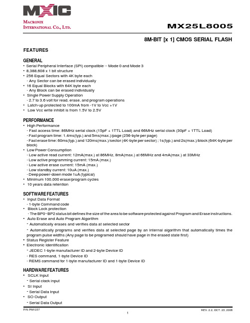
MX25L8005
8M-BIT [x 1] CMOS SERIAL FLASH
FEATURES
GENERAL • Serial Peripheral Interface (SPI) compatible -- Mode 0 and Mode 3 • 8,388,608 x 1 bit structure • 256 Equal Sectors with 4K byte each
The MX25L8005 provide sequential read operation on whole chip.
After program/erase command is issued, auto program/ erase algorithms which program/ erase and verify the specified page or byte /sector/block locations will be executed. Program command is executed on page (256 bytes) basis, and erase command is executes on chip or sector(4K-bytes) or block(64K-bytes).
MX25L8005
X-Decoder
Address Generator
Memory Array
SI
CS# SCLK
Page Buffer
Data Register
SRAM Buffer
Mode Logic
State Machine
Y-Decoder
HV Generator
Sense Amplifier
MacronixSerialMultiIO(MXSMIO)Flash:旺宏Flash串行..

The Ultimate Performance Flash MemoryMacronix Serial Multi I/O(MXSMIO TM) Flashw w w.m a c r o n i x.c o mWhy Use MXSMIO TM Family?3 Advantages of Macronix Serial Multi-I/O Flash Family4 Worldwide NOR Flash Trend5 The Fastest Performance Serial Flash on the Market 6Move Ahead of the Competition-MXSMIO TM Duplex7How to Design with Multi-I/O ?8Hardware Considerations Software ConsiderationsEnhanced Performance 9Pin Assignments9MXSMIO TM Flash Families11 3V Standard Serial Flash Families 11 Secure Serial Flash Family 13Serial ROM Family14Low Voltage Serial Flash Family15Thin & Small Packages17ContentsI n n o v a t i o n . Q u a l i t y . T e a m w o r k . E f f i c i e n c y . S e r v i ceof Macronix Serial Multi-I/OFlash FamilyToday more & more application require code execution & fast download functionality in their systems design. The Macronix Serial MXSMIO Flash products are available in Dual & Quad I/O capability to meet these system requirements. These products offer many advantages, such as:● Read performance comparable to Parallel Flash ● Shorter system boot-up time ● Layout simplification ● Less cross-talk wires● Lower power consumption● Reduced pin-count ( Controller or ASIC chip)● Reduce RAM buffer size for code execution (direct access from Serial Flash)●Lower system BOM costApplications Using Multi I/O Serial FlashMXSMIO Flash Family, ranging from 16Mb~128Mb, are already supported by leading chipset companies for a variety of applications including: ● Optical Disk Drive ● Digital TV ● DVD Player ● Wireless LAN ● Printer● Camera module ●Keyboard ControllerAnd several diverse applications will use this new generation "MXSMIO TM Flash Family" as their mainstream NOR Flash such as UWB , GE-PON, PLC, DSL & Set-Top Boxes, high speed servers, PC motherboards, Notebooks, graphic cards, HDDs, electronic dictionary, modems, and etc.Why Use MXSMIO TMFamily?Need Fast Speed? Look to Macronix ,the Leader in Serial Flash400200p a r a l l e l (x 16) 70n s p a r a l l e l (x 16) 90n s S PI 4x 50M H z (w /D T R )S P I 4x 75M H z S P I 4x 50M H zS P I 2x 75M H zS P I 2x 50M H zSP I 80M H z SP I 50M H zMb/sFastest Read Speed - Outperforming Parallel FlashData Transfer-(Throughput Mb/s)Catch the WorldWide Flash Trend:Parallel ➡ Serial ➡ Multi –I/O Serial Flash➡Serial Flash memories are rapidly taking over the code storage market from Parallel Flash in the same densities. The diagram above clearly indicates the benefits of moving to a Serial Flash device. With a parallel interconnect there are 38 external connections with 16 data bus and 19 address bus lines, whereas the SPI bus interface has only 4 interconnect signals. Not only is the layout simplified, the interface of the SPI bus reduces the size of the control chip as well. For example, in the ODD application, the controller size is reduced from a QFP240 to a QFP208 pin package and the routing based on this reduction not only reduces the size of the printed circuit board, but also reduces EMI and cross-talk.Despite the reduction in pin count and the cost advantage of the smaller package, the new MXSMIO TM Flash family also providesoutstanding access time, even better than Parallel Flash, which enables designers to use Serial Flash in speed critical applications.Leading Edge Breakthrough : Macronix is the leading Serial Flash supplier in the industry with largest market share (Web-Feet Research, March 2009). In 2009 Macronix continues to demonstrate its leadership in the Serial Flash market by offering the fastest products in the industry - MXSMIO TM Duplex Family - Quad I/O with Double Transfer Rate(DTR) mode with speeds up to 400MHz .The above diagram clearly demonstrates the Quad I/O DTR Serial Flash (MXSMIO TM Duplex) can exceed the performance of Parallel Flash. Our customers are already migrating from Parallel to Serial Flash.Even without DTR, the Macronix Quad I/O Serial Flash provides amazing performance approaching DRAM speeds of 300Mb/s, and even exceeding the 220 Mb/s speed mark of a fast 70ns, 16bit Parallel NOR-Flash .- Faster Than a Speeding BulletUnit:#of words outputHow to Design with Multi- I/O Works?Hardware ConsiderationsBoth Dual and Quad I/O Serial Flash from Macronix maintain backward compatibility - occupying exactly the same footprint used by conventional Single I/O Flash in 8-pin SOP packages. In other words, there is no need to modify the PCB or change the socket.Software ConsiderationsThe device identification should be properly specified to distinguish the traditional Single I/O Serial Flash from the new Multi-I/O ones. The following chart shows the command sets for customers using these devices in their systems. The recommended flow is to do READ ID check first : then to do DTR Quad I/O ID check, to Quad I/O ID check, and then Dual I/O ID and at last to do Single I/O ID check. If the IDs are allcorrect, it means that the device will support the abovementioned functions.READ CommandREAD 03 Hex FAST READ QB Hex Dual I/O READ BB Hex Quad I/O READ EB HexQuad I/O DTR READED Hex PROGRAM Command Quad I/O PAGE PROGRAM38 Hex READ IDREMS4D(READ ID for Quad I/O DDR Mode)CF HexREMS4(READ ID for Quad I/O Mode)DF Hex REMS2(READ ID for Dual I/O Mode)EF Hex REMS(READ ID for Single I/O Mode90 HexMulti I/O Serial Flash memories of the same density have the same device ID and are backward compatible to single I/O products. Applications currently using Single I/O mode can migrate to Multi I/O in the future, since the device IDs are the same. The software will need to be updated to address the Multi I/O commands.Key Features:●Quad I/O with Double Transfer Rate Serial Flash has - Quad I/O> Four I/O signals instead of one I/O signal - Double Transfer Rate(DTR)> Signals triggered on both rising and falling edge of clock ● Faster transfer of data from Serial Flash to DRAM or other chips ● No changes to hardware-command code based operation ● Backward compatible to Single/Dual/Quad I/O ● Wide voltage range of 2.7V to 3.6V ● Temperature range of -40̊C to + 85̊C●Fastest clock speed in the industry for serial flash -104MHz for fast read mode-400MHz for Quad I/O DTR operations●8-pin/16-pin SOP (SOIC) and 8-pin WSON (thin) Packages -16-pin SOP (SOIC) package support -16-pin SOP and KGD options.-8 pins for parallel mode programming to speed up production programming500400300200100Note : 1. Parallel Flash : 70ns 2. CLK rate : 80MHzCommand Sets for Serial Flash FamilyPin AssignmentsThe Macronix Multi-I/O Serial Flash doubles or even quadruples the data rate by changing the conventional Serial Input pin and Serial Out pin from single unidirectional data flow into multiple bi-directional data flows. The Dual I/O version uses SI and SO pins for both serial input and output, while the Quad I/O version uses SI and SO pins along with Write Protect pin and NC pin for both data input and output Functions. This doubling or quadrupling of data rate allows Serial Flash to compete with Parallel Flash for data read performance.Enhanced PerformanceAn added feature in the Multi-I/O DTR Serial Flash offers Enhanced Performance by saving 36 clock cycles compared to the Single I/O Flash. This further upgrades performance of the device. This feature eliminates the need to repeat the 8 cycles used for commands when successive operations are performed using the same command with random addresses. This feature advises the device that the current command is to be repeated during the next operation. If this current operation is a Multi-I/O read command, the Flash will be kept in the Multi-I/O Read Mode and the next read operation can be initiated by simply supplying a new address and the required number of dummy cycles.Serial Flash Pin Assignment (8-Pin Package)SIO 1WP#/SIO 2NC/SIO 3SIO OSIO 0SIO 1SIQuad I/ODual I/O Single I/OMX25L1005C 1Mb 2.7~3.6V 85Single 8-SOP , 8-USON(2×3mm)Y MX25L2005C 2Mb 2.7~3.6V 85Single 8-SOP , 8-WSON(6×5mm)Y MX25L4005C 4Mb 2.7~3.6V 85Single 8-SOP , 8-USON(4×4mm)8-WSON(6×5mm)Y MX25L80058Mb2.7~3.6V86Single8-SOP , 8-PDIP ,8-WSON(6×5mm),8-USON(4×4mm)YMX25L1605D 16Mb 2.7~3.6V 86Single 8-SOP , 8-PDIP , 16-SOP 8-WSON(6×5mm),8-USON(4×4mm)YMX25L3205D 32Mb 2.7~3.6V 86Single 8-SOP , 8-PDIP , 16-SOP , 8-WSON(6×5mm)8-USON(4×4mm)Y MX25L6405D 64Mb 2.7~3.6V 86Single 16-SOP ,8-WSON(6×8mm)Y*MX25L12805D128Mb2.7~3.6V50Single16-SOPY*Note : Y* Not recommended for new designsMX25L1605D16Mb2.7~3.6V86 / 100Single / Dual8-WSON(6×5mm),8-USON(4×4mm)YMX25L3205D 32Mb 2.7~3.6V 86 / 100Single / Dual 8-SOP , 8-PDIP , 16-SOP , 8-WSON(6×5mm)8-USON(4×4mm)Y MX25L6405D64Mb2.7~3.6V86 / 100Single / Dual16-SOP ,8-WSON(6×8mm)Y*Note : Y* Not recommended for new designsMX25L1635D 16Mb 2.7~3.6V 104/150/300Single / Dual / Quad 8-WSON(6×5mm)Y MX25L3235D 32Mb 2.7~3.6V 104/150/300Single / Dual / Quad 8-SOP , 16-SOP , 8-WSON(6×5mm)Y MX25L6445E 64Mb 2.7~3.6V 104/140/280/400Single / Dual /Quad / DTR 8-SOP , 16-SOP , 8-WSON(6×8mm)Y MX25L12845E128Mb2.7~3.6V104/140/280/400Single / Dual /Quad / DTR16-SOPYMXSMIO TMFlash Families3V Standard Serial Flash FamiliesMXSMIO TM Family includes high performance Serial Flash products with Dual I/O(MX25xx05) and Quad I/O(MX25xx35/45) operations which double and quadruple the read performance of systems for high-end consumer applications. Multiple I/O products range from 16Mb to 128Mb, while Single I/O products are provided from 512Kb to 128Mb densities. These products are offered in 4KB sectors and 64KB blocks and this architecture makes these products compatible to Serial Flash from other suppliers' architecture in the industry. Moreover, the Dua I/O and Quad I/O parts are backward compatible to the Single I/O versions which make them very convenient to use.Key Features:●Fast read performance :-Dual I/O - 150MHz read (4-dummy cycles)-Quad I/O - 300MHz read (6-dummy cycles)-Quad I/O DTR - 400MHz read (6-dummy cycles)Serial Flash products offer new security options for diverse customer needs: (Dual, Quad I/O option) ✓Flexible write protection ✓Secure OTP✓Additional special protectionSerial ROM FamilyPart number Density Voltage Clock Speed (MHz) I/O bus Package Mass ProductionMX23L1635D 16Mb 2.7~3.6V 104 / 50 / 75Single / Dual / Quad 8-SOP TBD MX23L3235D32Mb 2.7~3.6V 104 / 50 / 75Single / Dual / Quad 8-SOP TBD MX23L6445E 64Mb 2.7~3.6V 100 /140 / 280 /400Single / Dual /Quad / DTR 8-SOP TBD MX23L12845E128Mb2.7~3.6V100 /140 / 280 /400Single / Dual / Quad / DTR16-SOPTBDSerial ROM FamilyFor fixed software code applications like Printers, Game consoles, Toys, etc. Macronix providesa a high performance as well as costeffective Serial ROM Family of products.Featuring the same read performance as MXSMIO TM Family, yet taking advantage of low-cost OTP process technology, the Serial ROM Family products range from 16Mb to 128Mb and above with Dual and Quad I/O read capability with the same memory sector and block structure as MXSMIO TM Flash family.Key Features:●Fast read performance :-Dual I/O - 50MHz read (4-dummy cycles)-Quad I/O - 75MHz read (6-dummy cycles)● Individual Block Permanent Lock ●Individual Block LockSecured OTP area● Flexible Write Protection ●Additional Special ProtectionSecure Serial FlashAdvancedEnhancedStandardModern electronic systems are susceptible to unauthorized or accidental alteration of code and data. Non-volatile memory such as Mask-ROM or NOR flash contains critical information that could be altered or cloned. Systems manufacturers require innovative ways to secure their intellectual property and investment. New versions of Macronix Serial Flash are available as Secure Flash, offering various means of write protection (OTP and Temporary/Permanent Lock) and read protection within certain parts of the memory.MX25L1655D 16Mb 16M x 1/ 8M x 2/ 4M x 4104/150/300Single / Dual / Quad 24 BGA(6×8mm) MX25L3255D 32Mb 32M x 1/ 16M x 2/ 8M x 4104/150/300Single / Dual / Quad 8-SOP ,24 BGA(6×8mm) MX25L6455E 64Mb 64M x 1/ 32M x 2104/140/280/400Single / Dual /Quad / DTR 16-SOP ,24 BGA(6×8mm)MX25L12855E128Mb128M x 1/ 64M x 232M x 4104/140/280/400Single / Dual /Quad / DTR16-SOP ,24 BGA(10×13mm)Macronix Security Features2.5V Family25V4005C 4Mb x 150MHz Single8-WSON(6×5mm)Q3200925V40354Mb x 1 / x 2 / x 466/100/200Single/Dual/Quad 8-SOP ,8-WSON(6×5mm)Q3200925V80058Mb x 150MHz Single8-SOP , 8-WSON Y 25V80358Mbx 1 / x 2 / x 466/100/200Single/Dual/Quad8-SOP ,8-WSON(6×5mm)Q320091.8V /2.5V Serial Flash- Major SpecificationsVCC range1.65V to2.0V; -40°C to 85°C2.35V to3.6V or 2.25V to 2.75V; -40°C to 85°C Density4Mb, 8Mb, 16Mb, 32MbFastest clock speed in the industry for 1.8V serial flash25MHz (Normal read mode)40MHz (Fast read mode)80/132 MHz (Dual/Quad I/O read mode)Low standby currentStandby current 1uA(typ.), 5uA(max.) (resume time: 30µs)InterfaceStandard Serial Peripheral Interface (SPI)Multi-I/O -- Dual, Quad Input/OutputCommandIndustry standard commands for basic operations Enhanced commands for Macronix proprietary features Hardware pinsCS#, SCLK, SIO0, SIO1, WP#/SIO2, SIO31.8V Family25U40354Mb 4M x 1/ 2M x 2/ 1M x 440/80/132Single/Dual/Quad 8USON(4×4mm)Y 25U80358Mb 8M x 1/ 4M x 2/ 2M x 4 40/80/132Single/Dual/Quad 8-SOP ,8USON(4×4mm)Y 25U1635E 16Mb 16M x 1/ 8M x 2/ 4M x 4104/168/336Single/Dual/Quad 8-SOP ,8-USON(4×4mm) 201025U3235E32Mb32M x 1/ 16M x 2/ 8M x 4104/168/336Single/Dual/Quad8-SOP ,8-WSON(6×5mm)2010Low Voltage Serial Multi-I/O FlashFor low power consumption devices such as GPS, Bluetooth, HDD and cordless phones, Macronix offers 25U(1.8V) series and 25V(2.5V) series components enabling system designer to design for tight power budgets. By lowering the operating voltage and reducing operating current, Macronix Flash provides low power consumption which makes it a truly ideal product for battery-powered portableapplications.8-SOP(150 mil)●●●●●●8-SOP(200 mil)●●●●●Thin & Small Packages8 SOP (200mil)Length 7.9Width 5.23Thickness 2.16Pitch1.27(mm)8 WSON (6×5)Length 6Width 5Thickness 0.8Pitch1.27(mm)8 USON (4×4)Length 4Width4Thickness 0.6Pitch 0.8(mm)8 SOP (150mil)Length 6Width 5Thickness 1.75Pitch1.27(mm)8 WSON (8×6)Length8Width 6 Thickness 0.8Pitch1.27(mm)16 SOP (200mil)Length 10.3Width10.3Thickness2.65Pitch1.27(mm)8 USON (2×3)Length 3Width2Thickness 0.6(mm)Macronix provides Flash products with small form-factor packages, for space-constrained applications. Apart from industry standard packages, Known Good Die(KGD) solutions for System in Package(SiP) applications are also available.Multiple Package Options21Headquarters Macronix International Co., Ltd.16, Li-Hsin Road, Science Park, Hsinchu, TaiwanTel: +886-3-578-6688Fax: +886-3-563-2888Taipei Macronix International Co., Ltd.19F, 4, Min-Chuan E. Road, Sec. 3, Taipei, TaiwanTel: +886-2-2509-3300Fax: +886-2-2509-2200China - SuZhou Macronix (Hong Kong) Co., Limited, SuZhou O ceNo.5, XingHai Rd, SuZhou Industrial Park,SuZhou China 215021Tel: +86-512-6258-0888Fax: +86-512-6258-6799China - ShenZhen Macronix (Hong Kong) Co., Limited, ShenZhen O ceRoom 1401,Block A Tian An Hi-Tech Plaza TowerCheGongMiao Futian District Shenzhen 518040 PRCTel: +86-755-8343-3579Fax: +86-755-8343-8078China - Hong Kong Macronix (Hong Kong) Co., Ltd.702-703, 7/F, Building 9, Hong Kong Science Park,5 Science Park West Avenue, Sha Tin, N.T.Tel: +852-2607-4289Fax: +852-2607-4229Singapore Macronix Pte. Ltd.1 Marine Parade Central #11-03 Parkway Centre Singapore 449408Tel: +65-6346-5505Fax: +65-6348-8096 Japan Macronix Asia Limited.NKF Bldg. 5F, 1-2 Higashida-cho, Kawasaki-ku Kawasaki-shi, Kanagawa Pref. 210-0005, Japan Tel: +81-44-246-9100Fax: +81-44-246-9105Korea Macronix Asia Limited.#906, 9F, Kangnam Bldg., 1321-4, Seocho-Dong, Seocho-Ku,135-070, Seoul, Korea Tel: +82-2-588-6887Fax: +82-2-588-6828America Macronix America, Inc.680 North McCarthy Blvd. Milpitas, CA 95035, U.S.A.Tel: +1-408-262-8887Fax: +1-408-262-8810Europe Macronix Europe N.V.Koningin Astridlaan 59, Bus 1 1780 Wemmel Belgium Tel: +32-2-456-8020Fax: +32-2-456-8021About Macronix International Co., Ltd.Founded in 1989, Macronix International Co., Ltd. (TSE: 2337.TT) is a leading provider of innovative non-volatile memory (NVM) solutions. Macronix is the largest worldwide manufacturer of ROM products, and also provides a wide range of NOR Flash products across various densities. These are used in embedded systems, consumer, communication and enterprise applications.For more information, please visit the Company website at .Copyright © Macronix International Co., Ltd. 2009. All Rights Reserved. Macronix, MXIC, MXIC logo, MXSMIO, XtraROM, NBit and Macronix NBit are trademarks or registered trademark of Macronix International Co., Ltd.. The names and brands of other companies are for identi cation purposes only and may be claimed as the property of the respective companies.09 Apr.。
存储器类型
支持各厂家的SPI存储芯片的读写操作由于8脚串行BIOS芯片具有体积小,容量大的特点。
现在新型主板已经普遍使用如:W25X10(1MB) W25X20(2MB) W25X40(4MB) W25X80(8MB) MXprefix = st1 ns = "urn:schemas-microsoft-com:office:smarttags" 25L4005(4MB) MX25L8005(8MB) MX25L1605(16MB) MX25L32 05(32MB) ……。
对于这些8脚串行芯片,目前只有专业的编程器才可支持,但专业的编程器价格很贵,不是一般维修的用户可以拥有的;因此我们开发出一款可支持ST,WINBIND,AMIC,MXIC,SST,SPANSION,EON,PMC等厂家8脚串行芯片的USB接口编程小精灵,以便普通维修用户可以读写串行BIOS芯片。
1、支持目前市场上常见的8脚串行芯片。
理论最大支持128M容量的芯片,M25Pxx and S25FLxxx EN25T XX W25X10 (20,40,80) SA25F005 SST25VF512等系列WinbondAMICMXICSSTSPANSIONEONPMCW25X10VA25L10PMX25L1005SST25LF010ASM25P10-AVEN25P10 PM25LV010W25X20VA25L20PMX25L2005SST25LF020ASM25P20-VEN25P20P M25LV020W25X40VA25L40PMX25L4005SST25LF040AS25FL004AEN25P40P M25LV040W25X80VA25L80PMX25L8005SST25LF080AS25FL008AEN25P80P M25LV080W25X16VA25L16PMX25L1605SST25VF016BS25FL016AEN25P16W25X32VA25L15PMX25L3205SST25VF032BS25FL032AEN25P32编程器支持芯片列表:AMIC:·A25L05P,A25L10P,A25L20P,A25L40P,A25L80P,A25L16PATMEL:·AT25DF041A,AT25DF321,AT25F004,AT25F512A,AT25F2048,AT25F4096,AT25F1024A,AT25FS010,AT25FS040,AT26DF081A,·AT26DF161A,AT26DF321,AT26F004EON:EN25B05,EN25P05,EN25B10,EN25P10,EN25BF20,EN25P20,EN25F20,EN25B40,EN25P40,EN25F40,EN25B80,·EN25P80,EN25F80,EN25T80,EN25B16,EN25P16,EN25B32,EN25P32,EN25B64,EN25P64Excel Semiconductor Inc.ES25P10,ES25P20,ES25P40,ES25P80,ES25P16,ES25P32ESMT:F25L04UA,F25L004A,F25L008A,F25L016A,F25L032A,F25L064AST:M25P05A,M25P10A,M25P20,M25P40,M25P80,M25P16,M25P32,M25P64,M25PE10,M25PE20,M25PE40,M25PE80,M25PE16,M25PE32,M45PE10,M45PE20,M45PE40,M45PE80,M45PE16,M45PE32MXIC:MX25L512,MX25L1005,MX25L2005,MX25L4005,MX25L8005,MX25L1605,MX25L3205,MX25L6405NexFlash:NX25P80,NX25P16,NX25P32Chingis Technology CorporationPm25LV512,Pm25LV010,Pm25LV020,Pm25LV040,Pm25LV080,Pm25LV016,Pm25LV032,Pm25LV064Saifun SemiconductorsSA25F005,SA25F010,SA25F020,SA25F040,SA25F080,SA25F160,SA25F320,Silicon Storage Technology SSTSST25VF512A,SST25LF010A,SST25VF010A,SST25LF020A,SST25VF020,SST25LF040A,SST25VF040B,SST25LF080A,SST25VF080B,SST25VF016B,SST25VF032BWINBONDW25P10,W25X10,W25Q10,W25P20,W25X20,W25Q20,W25P40,W25X40,W25Q40,W25P80,W25X80,W25Q80,W25P16,W25X16,W25Q16,W25P32,W25X32,W25Q32,W25P64,W25X64,W25Q64。
MX25L4005AM2C-12G中文资料

MX25L4005A4M-BIT [x 1] CMOS SERIAL FLASH FEATURESGENERAL• Serial Peripheral Interface (SPI) compatible -- Mode 0 and Mode 3• 4,194,304 x 1 bit structure• 128 Equal Sectors with 4K byte each- Any Sector can be erased individually•8 Equal Blocks with 64K byte each- Any Block can be erased individually• Single Power Supply Operation- 2.7 to 3.6 volt for read, erase, and program operations• Latch-up protected to 100mA from -1V to Vcc +1V• Low Vcc write inhibit is from 1.5V to 2.5VPERFORMANCE• High Performance- Fast access time: 85MHz serial clock (15pF + 1TTL Load) and 66MHz serial clock (30pF + 1TTL Load)- Fast program time: 1.4ms(typ.) and 5ms(max.)/page (256-byte per page)- Fast erase time: 60ms(typ.) and 120ms(max.)/sector (4K-byte per sector) ; 1s(typ.) and 2s(max.)/block (64K-byte per block)• Low Power Consumption- Low active read current: 12mA(max.) at 85MHz, 8mA(max.) at 66MHz and 4mA(max.) at 33MHz- Low active programming current: 15mA (max.)- Low active erase current: 15mA (max.)- Low standby current: 10uA (max.)- Deep power-down mode 1uA (typical)• Minimum 100,000 erase/program cycles• 10 years data retentionSOFTWARE FEATURES• Input Data Format- 1-byte Command code•Block Lock protection- The BP0~BP2 status bit defines the size of the area to be software protected against Program and Erase instructions • Auto Erase and Auto Program Algorithm- Automatically erases and verifies data at selected sector- Automatically programs and verifies data at selected page by an internal algorithm that automatically times the program pulse widths (Any page to be programed should have page in the erased state first)•Status Register Feature•Electronic Identification- JEDEC 2-byte Device ID- RES command, 1-byte Device IDHARDWARE FEATURES• SCLK Input- Serial clock input• SI Input- Serial Data Input• SO Output- Serial Data Output• WP# pin- Hardware write protectionGENERAL DESCRIPTIONThe MX25L4005A is a CMOS 4,194,304 bit serial Flash memory, which is configured as 524,288 x 8 internally. The MX25L4005A feature a serial peripheral interface and software protocol allowing operation on a simple 3-wire bus. The three bus signals are a clock input (SCLK), a serial data input (SI), and a serial data output (SO). SPI access to the device is enabled by CS# input.The MX25L4005A provide sequential read operation on whole chip.After program/erase command is issued, auto program/ erase algorithms which program/ erase and verify the specified page or byte /sector/block locations will be executed. Program command is executed on page (256 bytes) basis, and erase command is executes on chip or sector(4K-bytes) or block(64K-bytes).To provide user with ease of interface, a status register is included to indicate the status of the chip. The status read command can be issued to detect completion status of a program or erase operation via WIP bit.When the device is not in operation and CS# is high, it is put in standby mode and draws less than 10uA DC current.The MX25L4005A utilize MXIC's proprietary memory cell, which reliably stores memory contents even after 100,000program and erase cycles.PIN CONFIGURATIONSSYMBOL DESCRIPTION CS#Chip SelectSI Serial Data Input SO Serial Data Output SCLK Clock InputHOLD#Hold, to pause the device without deselecting the device WP#Write ProtectionVCC + 3.3V Power Supply GNDGroundPIN DESCRIPTION8-PIN SOP (150/200mil)*8-LAND SON (6x5mm), WSON (6x5mm), USON (4x4mm)CS#SO WP#GNDVCC HOLD#SCLK SIC S #S O W P #G ND V C C H O L D #S C L K S I8-PIN PDIP (300mil)• HOLD# pin-pause the chip without diselecting the chip • PACKAGE- 8-pin SOP (150mil)- 8-pin SOP (200mil)- 8-pin PDIP (300mil)- 8-land SON (6x5mm, 1.0mm package height), which is not recommended for new design - 8-land WSON (6x5mm, 0.8mm package height)- 8-land USON (4x4mm) in development - All Pb-free devices are RoHS CompliantCS#SO WP#GNDVCC HOLD#SCLK SINote: 8-land SON is not recommended for new designBLOCK DIAGRAMDATA PROTECTIONThe MX25L4005A are designed to offer protection against accidental erasure or programming caused by spurious system level signals that may exist during power transition. During power up the device automatically resets the state machine in the Read mode. In addition, with its control register architecture, alteration of the memory contents only occurs after successful completion of specific command sequences. The device also incorporates several features to prevent inadvertent write cycles resulting from VCC power-up and power-down transition or system noise.•Power-on reset and tPUW: to avoid sudden power switch by system power supply transition, the power-on reset and tPUW (internal timer) may protect the Flash.• Valid command length checking: The command length will be checked whether it is at byte base and completed on byte boundary.• Write Enable (WREN) command: WREN command is required to set the Write Enable Latch bit (WEL) before other command to change data. The WEL bit will return to reset stage under following situation:- Power-up- Write Disable (WRDI) command completion- Write Status Register (WRSR) command completion- Page Program (PP) command completion- Sector Erase (SE) command completion- Block Erase (BE) command completion- Chip Erase (CE) command completion•Software Protection Mode (SPM): by using BP0-BP2 bits to set the part of Flash protected from data change.•Hardware Protection Mode (HPM): by using WP# going low to protect the BP0-BP2 bits and SRWD bit from data change.•Deep Power Down Mode: By entering deep power down mode, the flash device also is under protected from writing all commands except Release from deep power down mode command (RDP) and Read Electronic Signature command (RES).Table 1. Protected Area SizesStatus bit Protect level4Mb BP2BP1BP00000 (none)None001 1 (1 block)Block 7010 2 (2 blocks)Block 6-7 011 3 (4 blocks)Block 4-7 100 4 (8 blocks)All101 5 (All)All110 6 (All)All1117 (All)AllHOLD FEATUREHOLD# pin signal goes low to hold any serial communications with the device. The HOLD feature will not stop the operation of write status register, programming, or erasing in progress.The operation of HOLD requires Chip Select(CS#) keeping low and starts on falling edge of HOLD# pin signal while Serial Clock (SCLK) signal is being low (if Serial Clock signal is not being low, HOLD operation will not start until Serial Clock signal being low). The HOLD condition ends on the rising edge of HOLD# pin signal while Serial Clock(SCLK) signal is being low( if Serial Clock signal is not being low, HOLD operation will not end until Serial Clock being low), see Figure 1. Figure 1. Hold Condition OperationThe Serial Data Output (SO) is high impedance, both Serial Data Input (SI) and Serial Clock (SCLK) are don't care during the HOLD operation. If Chip Select (CS#) drives high during HOLD operation, it will reset the internal logic of the device. To re-start communication with chip, the HOLD# must be at high and CS# must be at low.Table 2. COMMAND DEFINITIONCOMMAND WREN WRDI RDID RDSR WRSR READ Fast Read (byte)(write(write(read ident-(read status(write status(read data)(fast read Enable)disable)ification)register)register)data)1st06 Hex04 Hex9F Hex05 Hex01 Hex03 Hex0B Hex2nd AD1AD13rd AD2AD24th AD3AD35th xAction sets the reset the output the to read out to write new n bytes(WEL)(WEL)manufacturer the status values to the read outwrite write ID and 2-byte register status register untilenable enable device ID CS# goeslatch bit latch bit highCOMMAND SE BE CE PP DP RDP RES REMS (Read (byte)(Sector(Block(Chip(Page(Deep(Release(Read Electronic Erase)Erase)Erase)Program)Power from Deep Electronic ManufacturerDown)Power-down)ID)& Device ID) 1st20 Hex52 or60 or 02 Hex B9 Hex AB Hex AB Hex90 HexD8 Hex C7 Hex2nd AD1AD1AD1x x3rd AD2AD2AD2x x4th AD3AD3AD3x ADD(1)5thAction Output themanufacturerID and deviceID(1) ADD=00H will output the manufacturer's ID first and ADD=01H will output device ID first.(2) It is not recommended to adopt any other code which is not in the above command definition table.Table 3. Memory OrganizationBlockSector 12707F000h 07FFFFh……..…….……..112070000h 070FFFh 11106F000h 06FFFFh……..…….……..96060000h 060FFFh 9505F000h 05FFFFh……..…….……..80050000h 050FFFh 7904F000h 04FFFFh……..…….……..64040000h 040FFFh 6303F000h 03FFFFh……..…….……..48030000h 030FFFh 4702F000h 02FFFFh……..…….……..32020000h 020FFFh 3101F000h 01FFFFh……..…….……..16010000h 010FFFh 1500F000h 00FFFFh……..…….……..3003000h 003FFFh 2002000h 002FFFh 001000h 001FFFh 000000h 000FFFh10Address Range7654321DEVICE OPERATION1.Before a command is issued, status register should be checked to ensure device is ready for the intended operation.2.When incorrect command is inputted to this LSI, this LSI becomes standby mode and keeps the standby mode until next CS# falling edge. In standby mode, SO pin of this LSI should be High-Z.3.When correct command is inputted to this LSI, this LSI becomes active mode and keeps the active mode until next CS# rising edge.4.Input data is latched on the rising edge of Serial Clock(SCLK) and data shifts out on the falling edge of SCLK. The difference of SPI mode 0 and mode 3 is shown as Figure 2.Figure 2. SPI Modes Supported5.For the following instructions: RDID, RDSR, READ, FAST_READ, RES and REMS the shifted-in instruction sequence is followed by a data-out sequence. After any bit of data being shifted out, the CS# can be high. For the following instructions: WREN, WRDI, WRSR, SE, BE, CE, PP, RDP and DP the CS# must go high exactly at the byte boundary;otherwise, the instruction will be rejected and not executed.6.During the progress of Write Status Register, Program, Erase operation, to access the memory array is neglected and not affect the current operation of Write Status Register, Program, Erase.Note:CPOL indicates clock polarity of SPI master, CPOL=1 for SCLK high while idle, CPOL=0 for SCLK low while not transmitting. CPHA indicates clock phase. The combination of CPOL bit and CPHA bit decides which SPI mode is supported.SCLKMSBCPHAshift inshift outSI 01CPOL0(SPI mode 0)(SPI mode 3)1SO SCLKMSBCOMMAND DESCRIPTION(1) Write Enable (WREN)The Write Enable (WREN) instruction is for setting Write Enable Latch (WEL) bit. For those instructions like PP, SE, BE, CE, and WRSR, which are intended to change the device content, should be set every time after the WREN instruction setting the WEL bit.The sequence of issuing WREN instruction is: CS# goes low-> sending WREN instruction code-> CS# goes high. (see Figure 11)(2) Write Disable (WRDI)The Write Disable (WRDI) instruction is for resetting Write Enable Latch (WEL) bit.The sequence of issuing WRDI instruction is: CS# goes low-> sending WRDI instruction code-> CS# goes high. (see Figure 12)The WEL bit is reset by following situations:- Power-up- Write Disable (WRDI) instruction completion- Write Status Register (WRSR) instruction completion- Page Program (PP) instruction completion- Sector Erase (SE) instruction completion- Block Erase (BE) instruction completion- Chip Erase (CE) instruction completion(3) Read Identification (RDID)The RDID instruction is for reading the manufacturer ID of 1-byte and followed by Device ID of 2-byte. The MXIC Manufacturer ID is C2(hex), the memory type ID is 20(hex) as the first-byte device ID, and the individual device ID of second-byte ID is as followings: 13(hex) for MX25L4005A.The sequence of issuing RDID instruction is: CS# goes low-> sending RDID instruction code -> 24-bits ID data out on SO -> to end RDID operation can use CS# to high at any time during data out. (see Figure. 13)While Program/Erase operation is in progress, it will not decode the RDID instruction, so there's no effect on the cycle of program/erase operation which is currently in progress. When CS# goes high, the device is at standby stage.(4) Read Status Register (RDSR)The RDSR instruction is for reading Status Register Bits. The Read Status Register can be read at any time (even in program/erase/write status register condition) and continuously. It is recommended to check the Write in Progress (WIP) bit before sending a new instruction when a program, erase, or write status register operation is in progress.The sequence of issuing RDSR instruction is: CS# goes low-> sending RDSR instruction code-> Status Register data out on SO (see Figure. 14)The definition of the status register bits is as below:WIP bit. The Write in Progress (WIP) bit, a volatile bit, indicates whether the device is busy in program/erase/write status register progress. When WIP bit sets to 1, which means the device is busy in program/erase/write status register progress. When WIP bit sets to 0, which means the device is not in progress of program/erase/write status register cycle.WEL bit. The Write Enable Latch (WEL) bit, a volatile bit, indicates whether the device is set to internal write enable latch. When WEL bit sets to 1, which means the internal write enable latch is set, the device can accept program/erase/write status register instruction. When WEL bit sets to 0, which means no internal write enable latch; the device will not accept program/erase/write status register instruction.BP2, BP1, BP0 bits. The Block Protect (BP2, BP1, BP0) bits, non-volatile bits, indicate the protected area(as defined in table 1) of the device to against the program/erase instruction without hardware protection mode being set. To write the Block Protect (BP2, BP1, BP0) bits requires the Write Status Register (WRSR) instruction to be executed. Those bits define the protected area of the memory to against Page Program (PP), Sector Erase (SE), Block Erase (BE) and Chip Erase(CE) instructions (only if all Block Protect bits set to 0, the CE instruction can be executed)SRWD bit. The Status Register Write Disable (SRWD) bit, non-volatile bit, is operated together with Write Protection (WP#) pin for providing hardware protection mode. The hardware protection mode requires SRWD sets to 1 and WP# pin signal is low stage. In the hardware protection mode, the Write Status Register (WRSR) instruction is no longer accepted for execution and the SRWD bit and Block Protect bits (BP2, BP1, BP0) are read only.bit 7bit 6bit 5bit 4bit 3bit 2bit 1bit 0SRWD BP2BP1BP0WEL WIPStatus00the level of the level of the level of(write enable(write in progress Register Write protected protected protected latch)bit) Protect block block block1= status(note 1)(note 1)(note 1)1=write enable1=write operation register write0=not write0=not in write disable enable operationNote:1. See the table "Protected Area Sizes".2. The endurance cycles of protect bits are 100,000 cycles; however, the tW time out spec of protect bits is relaxedas tW = N x 15ms (N is a multiple of 10,000 cycles, ex. N = 2 for 20,000 cycles) after 10,000 cycles on those bits.(5) Write Status Register (WRSR)The WRSR instruction is for changing the values of Status Register Bits. Before sending WRSR instruction, the Write Enable (WREN) instruction must be decoded and executed to set the Write Enable Latch (WEL) bit in advance. The WRSR instruction can change the value of Block Protect (BP2, BP1, BP0) bits to define the protected area of memory (as shown in table 1). The WRSR also can set or reset the Status Register Write Disable (SRWD) bit in accordance with Write Protection (WP#) pin signal. The WRSR instruction cannot be executed once the Hardware Protected Mode (HPM) is entered.The sequence of issuing WRSR instruction is: CS# goes low-> sending WRSR instruction code-> Status Register data on SI-> CS# goes high. (see Figure 15)The WRSR instruction has no effect on b6, b5, b1, b0 of the status register.The CS# must go high exactly at the byte boundary; otherwise, the instruction will be rejected and not executed. The self-timed Write Status Register cycle time (tW) is initiated as soon as Chip Select (CS#) goes high. The Write in Progress (WIP) bit still can be check out during the Write Status Register cycle is in progress. The WIP sets 1 during the tW timing,and sets 0 when Write Status Register Cycle is completed, and the Write Enable Latch (WEL) bit is reset.Table 4. Protection ModesNote:1. As defined by the values in the Block Protect (BP2, BP1, BP0) bits of the Status Register, as shown in Table 1.As the above table showing, the summary of the Software Protected Mode (SPM) and Hardware Protected Mode (HPM).Software Protected Mode (SPM):-When SRWD bit=0, no matter WP# is low or high, the WREN instruction may set the WEL bit and can change the valuesof SRWD, BP2, BP1, BP0. The protected area, which is defined by BP2, BP1, BP0, is at software protected mode (SPM).-When SRWD bit=1 and WP# is high, the WREN instruction may set the WEL bit can change the values of SRWD, BP2,BP1, BP0. The protected area, which is defined by BP2, BP1, BP0, is at software protected mode (SPM).Note: If SRWD bit=1 but WP# is low, it is impossible to write the Status Register even if the WEL bit has previously been set. It is rejected to write the Status Register and not be executed.ModeStatus register condition Software protection mode(SPM)Status register can be written in (WEL bit is set to "1") and the SRWD, BP0-BP2bits can be changedWP# and SRWD bit status MemoryWP#=1 and SRWD bit=0, or WP#=0 and SRWD bit=0, or WP#=1 and SRWD=1The protected area cannot be program or erase.The protected area cannot be program or erase.WP#=0, SRWD bit=1The SRWD, BP0-BP2 ofstatus register bits cannot be changedHardware protection mode (HPM)Hardware Protected Mode (HPM):-When SRWD bit=1, and then WP# is low (or WP# is low before SRWD bit=1), it enters the hardware protected mode (HPM). The data of the protected area is protected by software protected mode by BP2, BP1, BP0 and hardware protected mode by the WP# to against data modification.Note: to exit the hardware protected mode requires WP# driving high once the hardware protected mode is entered. If the WP# pin is permanently connected to high, the hardware protected mode can never be entered; only can use software protected mode via BP2, BP1, BP0.(6) Read Data Bytes (READ)The read instruction is for reading data out. The address is latched on rising edge of SCLK, and data shifts out on the falling edge of SCLK at a maximum frequency fR. The first address byte can be at any location. The address is automatically increased to the next higher address after each byte data is shifted out, so the whole memory can be read out at a single READ instruction. The address counter rolls over to 0 when the highest address has been reached.The sequence of issuing READ instruction is: CS# goes low-> sending READ instruction code-> 3-byte address on SI -> data out on SO-> to end READ operation can use CS# to high at any time during data out. (see Figure. 16)(7) Read Data Bytes at Higher Speed (FAST_READ)The FAST_READ instruction is for quickly reading data out. The address is latched on rising edge of SCLK, and data of each bit shifts out on the falling edge of SCLK at a maximum frequency fC. The first address byte can be at any location. The address is automatically increased to the next higher address after each byte data is shifted out, so the whole memory can be read out at a single FAST_READ instruction. The address counter rolls over to 0 when the highest address has been reached.The sequence of issuing FAST_READ instruction is: CS# goes low-> sending FAST_READ instruction code-> 3-byte address on SI-> 1-dummy byte address on SI->data out on SO-> to end FAST_READ operation can use CS# to high at any time during data out. (see Figure. 17)While Program/Erase/Write Status Register cycle is in progress, FAST_READ instruction is rejected without any impact on the Program/Erase/Write Status Register current cycle.(8) Sector Erase (SE)The Sector Erase (SE) instruction is for erasing the data of the chosen sector to be "1". A Write Enable (WREN) instruction must execute to set the Write Enable Latch (WEL) bit before sending the Sector Erase (SE). Any address of the sector (see table 3) is a valid address for Sector Erase (SE) instruction. The CS# must go high exactly at the byte boundary (the latest eighth of address byte been latched-in); otherwise, the instruction will be rejected and not executed.Address bits [Am-A12] (Am is the most significant address) select the sector address.The sequence of issuing SE instruction is: CS# goes low -> sending SE instruction code-> 3-byte address on SI -> CS# goes high. (see Figure 19)The self-timed Sector Erase Cycle time (tSE) is initiated as soon as Chip Select (CS#) goes high. The Write in Progress (WIP) bit still can be check out during the Sector Erase cycle is in progress. The WIP sets 1 during the tSE timing, and sets 0 when Sector Erase Cycle is completed, and the Write Enable Latch (WEL) bit is reset. If the page is protected by BP2, BP1, BP0 bits, the Sector Erase (SE) instruction will not be executed on the page.(9) Block Erase (BE)The Block Erase (BE) instruction is for erasing the data of the chosen block to be "1". A Write Enable (WREN) instruction must execute to set the Write Enable Latch (WEL) bit before sending the Block Erase (BE). Any address of the block (see table 3) is a valid address for Block Erase (BE) instruction. The CS# must go high exactly at the byte boundary (the latest eighth of address byte been latched-in); otherwise, the instruction will be rejected and not executed.The sequence of issuing BE instruction is: CS# goes low -> sending BE instruction code-> 3-byte address on SI -> CS# goes high. (see Figure 20)The self-timed Block Erase Cycle time (tBE) is initiated as soon as Chip Select (CS#) goes high. The Write in Progress (WIP) bit still can be check out during the Sector Erase cycle is in progress. The WIP sets 1 during the tBE timing, and sets 0 when Sector Erase Cycle is completed, and the Write Enable Latch (WEL) bit is reset. If the page is protected by BP2, BP1, BP0 bits, the Block Erase (BE) instruction will not be executed on the page.(10) Chip Erase (CE)The Chip Erase (CE) instruction is for erasing the data of the whole chip to be "1". A Write Enable (WREN) instruction must execute to set the Write Enable Latch (WEL) bit before sending the Chip Erase (CE). Any address of the sector (see table 3) is a valid address for Chip Erase (CE) instruction. The CS# must go high exactly at the byte boundary( the latest eighth of address byte been latched-in); otherwise, the instruction will be rejected and not executed.The sequence of issuing CE instruction is: CS# goes low-> sending CE instruction code-> CS# goes high. (see Figure 20)The self-timed Chip Erase Cycle time (tCE) is initiated as soon as Chip Select (CS#) goes high. The Write in Progress (WIP) bit still can be check out during the Chip Erase cycle is in progress. The WIP sets 1 during the tCE timing, and sets 0 when Chip Erase Cycle is completed, and the Write Enable Latch (WEL) bit is reset. If the chip is protected by BP2, BP1, BP0 bits, the Chip Erase (CE) instruction will not be executed. It will be only executed when BP2, BP1, BP0 all set to "0".(11) Page Program (PP)The Page Program (PP) instruction is for programming the memory to be "0". A Write Enable (WREN) instruction must execute to set the Write Enable Latch (WEL) bit before sending the Page Program (PP). The device programs only the last 256 data bytes sent to the device. If the entire 256 data bytes are going to be programmed, A7-A0 (The eight least significant address bits) should be set to 0. If the eight least significant address bits (A7-A0) are not all 0, all transmitted data going beyond the end of the current page are programmed from the start address of the same page (from the address A7-A0 are all 0). If more than 256 bytes are sent to the device, the data of the last 256-byte is programmed at the request page and previous data will be disregarded. If less than 256 bytes are sent to the device, the data is programmed at the requested address of the page without effect on other address of the same page.The sequence of issuing PP instruction is: CS# goes low-> sending PP instruction code-> 3-byte address on SI-> at least 1-byte on data on SI-> CS# goes high. (see Figure 18)The CS# must be kept to low during the whole Page Program cycle; The CS# must go high exactly at the byte boundary( the latest eighth bit of data being latched in), otherwise the instruction will be rejected and will not be executed.The self-timed Page Program Cycle time (tPP) is initiated as soon as Chip Select (CS#) goes high. The Write in Progress (WIP) bit still can be check out during the Page Program cycle is in progress. The WIP sets 1 during the tPP timing, and sets 0 when Page Program Cycle is completed, and the Write Enable Latch (WEL) bit is reset. If the page is protected by BP3, BP2, BP1, BP0 bits, the Page Program (PP) instruction will not be executed.(12) Deep Power-down (DP)The Deep Power-down (DP) instruction is for setting the device on the minimizing the power consumption (to entering the Deep Power-down mode), the standby current is reduced from ISB1 to ISB2). The Deep Power-down mode requires the Deep Power-down (DP) instruction to enter, during the Deep Power-down mode, the device is not active and all Write/ Program/Erase instruction are ignored. When CS# goes high, it's only in standby mode not deep power-down mode. It's different from Standby mode.The sequence of issuing DP instruction is: CS# goes low-> sending DP instruction code-> CS# goes high. (see Figure 22) Once the DP instruction is set, all instruction will be ignored except the Release from Deep Power-down mode (RDP) and Read Electronic Signature (RES) instruction. (RES instruction to allow the ID been read out). When Power-down, the deep power-down mode automatically stops, and when power-up, the device automatically is in standby mode. For RDP instruction the CS# must go high exactly at the byte boundary (the latest eighth bit of instruction code been latched-in); otherwise, the instruction will not executed. As soon as Chip Select (CS#) goes high, a delay of tDP is required before entering the Deep Power-down mode and reducing the current to ISB2.(13) Release from Deep Power-down (RDP), Read Electronic Signature (RES)The Release from Deep Power-down (RDP) instruction is terminated by driving Chip Select (CS#) High. When Chip Select (CS#) is driven High, the device is put in the Stand-by Power mode. If the device was not previously in the Deep Power-down mode, the transition to the Stand-by Power mode is immediate. If the device was previously in the Deep Power-down mode, though, the transition to the Stand-by Power mode is delayed by tRES2, and Chip Select (CS#) must remain High for at least tRES2(max), as specified in Table 6. Once in the Stand-by Power mode, the device waits to be selected, so that it can receive, decode and execute instructions.RES instruction is for reading out the old style of 8-bit Electronic Signature, whose values are shown as table of ID Definitions. This is not the same as RDID instruction. It is not recommended to use for new design. For new deisng, please use RDID instruction. Even in Deep power-down mode, the RDP and RES are also allowed to be executed, only except the device is in progress of program/erase/write cycle; there's no effect on the current program/erase/write cycle in progress.The sequence is shown as Figure 23,24.The RES instruction is ended by CS# goes high after the ID been read out at least once. The ID outputs repeatedly if continuously send the additional clock cycles on SCLK while CS# is at low. If the device was not previously in Deep Power-down mode, the device transition to standby mode is immediate. If the device was previously in Deep Power-down mode, there's a delay of tRES2 to transit to standby mode, and CS# must remain to high at least tRES2(max). Once in the standby mode, the device waits to be selected, so it can be receive, decode, and execute instruction.The RDP instruction is for releasing from Deep Power Down Mode.。
- 1、下载文档前请自行甄别文档内容的完整性,平台不提供额外的编辑、内容补充、找答案等附加服务。
- 2、"仅部分预览"的文档,不可在线预览部分如存在完整性等问题,可反馈申请退款(可完整预览的文档不适用该条件!)。
- 3、如文档侵犯您的权益,请联系客服反馈,我们会尽快为您处理(人工客服工作时间:9:00-18:30)。
16M-BIT [x 1 / x 2] CMOS SERIAL FLASH 32M-BIT [x 1 / x 2] CMOS SERIAL FLASH 64M-BIT [x 1 / x 2] CMOS SERIAL FLASHFEATURESGENERAL• Serial Peripheral Interface compatible -- Mode 0 and Mode 3• 16M:16,777,216 x 1 bit structure or 8,388,608 x 2 bits (two I/O read mode) structure 32M:33,554,432 x 1 bit structure or 16,772,216 x 2 bits (two I/O read mode) structure 64M:67,108,864 x 1 bit structure or 33,554,432 x 2 bits (two I/O read mode) structure • 512 Equal Sectors with 4K byte each (16Mb) 1024 Equal Sectors with 4K byte each (32Mb) 2048 Equal Sectors with 4K byte each (64Mb) - Any Sector can be erased individually• 32 Equal Blocks with 64K byte each (16Mb) 64 Equal Blocks with 64K byte each (32Mb) 128 Equal Blocks with 64K byte each (64Mb) - Any Block can be erased individually • Single Power Supply Operation- 2.7 to 3.6 volt for read, erase, and program operations • Latch-up protected to 100mA from -1V to Vcc +1VPERFORMANCE • High Performance- Fast access time: 86MHz serial clock (15pF + 1TTL Load) and 66MHz serial clock (30pF + 1TTL Load) - Serial clock of two I/O read mode : 50MHz (15pF + TTL Load), which is equivalent to 100MHz - Fast program time: 1.4ms(typ.) and 5ms(max.)/page (256-byte per page) - Byte program time: 9us (typical)- Continuously program mode (automatically increase address under word program mode)- Fast erase time: 60ms(typ.) /sector (4K-byte per sector) ; 0.7s(typ.) /block (64K-byte per block); 14s(typ.) /chip for 16Mb, 25s(typ.) for 32Mb, and 50s(typ.) for 64Mb • Low Power Consumption- Low active read current: 25mA(max.) at 86MHz, 20mA(max.) at 66MHz and 10mA(max.) at 33MHz - Low active programming current: 20mA (max.) - Low active erase current: 20mA (max.) - Low standby current: 20uA (max.) - Deep power-down mode 1uA (typical)• Typical 100,000 erase/program cycles • 20 years of data retentionSOFTWARE FEATURES • Input Data Format- 1-byte Command code • Advanced Security Features - Block lock protectionThe BP0-BP3 status bit defines the size of the area to be software protection against program and erase instruc-tions- Additional 512-bit secured OTP for unique identifier • Auto Erase and Auto Program Algorithm- Automatically erases and verifies data at selected sector- Automatically programs and verifies data at selected page by an internal algorithm that automatically times the program pulse widths (Any page to be programed should have page in the erased state first)MX25L1605D MX25L3205D MX25L6405D• Status Register Feature• Electronic Identification- JEDEC 1-byte manufacturer ID and 2-byte device ID- RES command for 1-byte Device ID- Both REMS and REMS2 commands for 1-byte manufacturer ID and 1-byte device IDHARDWARE FEATURES• SCLK Input- Serial clock input• SI Input- Serial Data Input• SO Output- Serial Data Output• WP#/ACC pin- Hardware write protection and program/erase acceleration• HOLD# pin- pause the chip without diselecting the chip• PACKAGE- 16-pin SOP (300mil)- 8-land WSON (8x6mm or 6x5mm)- 8-pin SOP (200mil, 150mil)- 8-pin PDIP (300mil)- 8-land USON (4x4mm)- All Pb-free devices are RoHS CompliantALTERNATIVE• Security Serial Flash (MX25L1615D/MX25L3215D/MX25L6415D) may provides additional protection features for option. The datasheet is provided under NDA.GENERAL DESCRIPTIONThe MX25L1605D are 16,777,216 bit serial Flash memory, which is configured as 2,097,152 x 8 internally. When it is in two I/O read mode, the structure becomes 8,388,608 bits x 2. The MX25L3205D are 33,554,432 bit serial Flash memory, which is configured as 4,194,304 x 8 internally. When it is in two I/O read mode, the structure be-comes 16,772,216 bits x 2. The MX25L6405D are 67,108,864 bit serial Flash memory, which is configured as 8,388,608 x 8 internally. When it is in two I/O read mode, the structure becomes 33,554,432 bits x 2. (please refer to the "Two I/O Read mode" section). The MX25L1605D/3205D/6405D feature a serial peripheral interface and software proto-col allowing operation on a simple 3-wire bus. The three bus signals are a clock input (SCLK), a serial data input (SI), and a serial data output (SO). Serial access to the device is enabled by CS# input.When it is in two I/O read mode, the SI pin and SO pin become SIO0 pin and SIO1 pin for address/dummy bits in-put and data output.The MX25L1605D/3205D/6405D provides sequential read operation on whole chip.After program/erase command is issued, auto program/ erase algorithms which program/ erase and verify the specified page or sector/block locations will be executed. Program command is executed on byte basis, or page (256 bytes) basis, or word basis for Continuously program mode, and erase command is executes on sector (4K-byte), or block (64K-byte), or whole chip basis.Table 1. Additional Feature ComparisonTo provide user with ease of interface, a status register is included to indicate the status of the chip. The status read command can be issued to detect completion status of a program or erase operation via WIP bit.Advanced security features enhance the protection and security functions, please see security features section for more details.When the device is not in operation and CS# is high, it is put in standby mode and draws less than 20uA DC cur-rent.The MX25L1605D/3205D/6405D utilizes Macronix's proprietary memory cell, which reliably stores memory con-tents even after typical 100,000 program and erase cycles.Additional Features Part Name Protection and Security Read Performance IdentifierFlexible BlockProtection(BP0-BP3)512-bit securedOTP2 I/O Read (50MHz)Device ID (command: AB hex)Device ID (command: 90 hex)Device ID (command: EF hex)RDID(command: 9Fhex)MX25L1605D V V V 14 (hex)C2 14 (hex)(if ADD=0) C2 14 (hex)(if ADD=0) C2 20 15 (hex)MX25L3205D V V V 15 (hex)C2 15 (hex)(if ADD=0) C2 15 (hex)(if ADD=0) C2 20 16 (hex)MX25L6405DVVV16 (hex)C2 16 (hex)(if ADD=0) C2 16 (hex)(if ADD=0)C2 20 17 (hex)PIN CONFIGURATIONSSYMBOL DESCRIPTION CS#Chip SelectSI/SIO0Serial Data Input (for 1 x I/O)/ Serial Data Input & Output (for 2xI/O read mode)SO/SIO1Serial Data Output (for 1 x I/O)/ Serial DataInput & Output (for 2xI/O read mode)SCLK Clock InputWP#/ACC Write protection: connect to GND ; 9.5~10.5Vfor program/erase acceleration: connect to 9.5~10.5VHOLD#Hold, to pause the device withoutdeselecting the deviceVCC + 3.3V Power Supply GND GroundPIN DESCRIPTION16-PIN SOP (300mil)8-LAND WSON (8x6mm, 6x5mm), USON (4x4mm)8-PIN SOP (200mil, 150mil)PACKAGE OPTIONS16M 32M 64M150mil 8-SOP V 200mil 8-SOP V V 300mil 16-SOP V V V300mil 8-PDIP V V 6x5mm WSON V V 8x6mm WSON V4x4mm USONVV12345678HOLD#VCC NC NC NC NC CS#SO/SIO1161514131211109SCLK SI/SIO0NC NC NC NC GND WP#/ACCCS#SO/SIO1WP#/ACCGND VCC HOLD#SCLK SI/SIO0CS#SO/SIO1WP#/ACC GND VCC HOLD#SCLK SI/SIO01234CS#SO/SIO1WP#/ACC GND 8765VCC HOLD#SCLK SI/SIO08-PIN PDIP (300mil)BLOCK DIAGRAMDATA PROTECTIONThe MX25L1605D/3205D/6405D is designed to offer protection against accidental erasure or programming caused by spurious system level signals that may exist during power transition. During power up the device automatically resets the state machine in the standby mode. In addition, with its control register architecture, alteration of the memory contents only occurs after successful completion of specific command sequences. The device also incor-porates several features to prevent inadvertent write cycles resulting from VCC power-up and power-down transi-tion or system noise.• Valid command length checking: The command length will be checked whether it is at byte base and completed on byte boundary.• Write Enable (WREN) command: WREN command is required to set the Write Enable Latch bit (WEL) before other command to change data. The WEL bit will return to reset stage under following situation:- Power-up- Write Disable (WRDI) command completion- Write Status Register (WRSR) command completion- Page Program (PP) command completion- Continuously Program mode (CP) instruction completion- Sector Erase (SE) command completion- Block Erase (BE) command completion- Chip Erase (CE) command completion• Deep Power Down Mode: By entering deep power down mode, the flash device also is under protected from writing all commands except Release from deep power down mode command (RDP) and Read Electronic Sig-nature command (RES).• Advanced Security Features: there are some protection and securuity features which protect content from inad-vertent write and hostile access.I. Block lock protection- The Software Protected Mode (SPM) use (BP3, BP2, BP1, BP0) bits to allow part of memory to be protected as read only. The proected area definition is shown as table of "Protected Area Sizes", the protected areas are more flexible which may protect various area by setting value of BP0-BP3 bits.Please refer to table of "protected area sizes".- The Hardware Proteced Mode (HPM) use WP#/ACC to protect the (BP3, BP2, BP1, BP0) bits and SRWD bit.Table 2. Protected Area SizesStatus bit Protect LevelBP3BP2BP1BP016Mb32Mb64Mb00000 (none)0 (none)0 (none)0001 1 (1block, block 31th) 1 (1block, block 63th) 1 (2block, block 126th-127th) 0010 2 (2blocks, block 30th-31th) 2 (2blocks, block 62th-63th) 2 (4blocks, block 124th-127th) 0011 3 (4blocks, block 28th-31th) 3 (4blocks, block 60th-63th) 3 (8blocks, block 120th-127th) 0100 4 (8blocks, block 24th-31th) 4 (8blocks, block 56th-63th)4(16blocks, block 112th-127th) 0101 5 (16blocks, block 16th-31th)5 (16blocks, block 48th-63th)5 (32blocks, block 96th-127th) 0110 6 (32blocks, all) 6 (32blocks, block 32th-63th)6 (64blocks, block 64th-127th) 01117 (32blocks, all)7 (64blocks, all)7 (128blocks, all)10008 (32blocks, all)8 (64blocks, all)8 (128blocks, all)10019 (32blocks, all)9 (32blocks, block 0th-31th)9 (64blocks, 0th-63th) 101010 (16blocks, block 0th-15th)10 (48blocks, block 0th-47th)10 (96blocks, block 0th-95th) 101111 (24blocks, block 0th-23th)11 (56blocks, block 0th-55th)11 (112blocks, block 0th-111th) 110012 (28blocks, block 0th-27th)12 (60blocks, block 0th-59th)12(120blocks, block 0th-119th) 110113 (30blocks, block 0th-29th)13 (62blocks, block 0th-61th)13(124blocks, block 0th-123th) 111014 (31blocks, block 0th-30th)14 (63blocks, block 0th-62th)14(126blocks, block 0th-125th) 111115 (32blocks, all)15 (64blocks, all)15 (128blocks, all)II. Additional 512-bit secured OTP for unique identifier: to provide 512-bit one-time program area for setting device unique serial number - Which may be set by factory or system customer. Please refer to table 3. 512-bit secured OTP definition.- Security register bit 0 indicates whether the chip is locked by factory or not.- To program the 512-bit secured OTP by entering 512-bit secured OTP mode (with ENSO command), and go-ing through normal program procedure, and then exiting 512-bit secured OTP mode by writing EXSO command.- Customer may lock-down the customer lockable secured OTP by writing WRSCUR(write security register) command to set customer lock-down bit1 as "1". Please refer to table of "security register definition" for security register bit definition and table of "512-bit secured OTP definition" for address range definition.- Note: Once lock-down whatever by factory or customer, it cannot be changed any more. While in 512-bit se-cured OTP mode, array access is not allowed.Table 3. 512-bit Secured OTP DefinitionAddress range Size Standard Factory Lock Customer Lockxxxx00~xxxx0F128-bit ESN (electrical serial number)Determined by customer xxxx10~xxxx3F 384-bit N/AHOLD FEATURESHOLD# pin signal goes low to hold any serial communications with the device. The HOLD feature will not stop the operation of write status register, programming, or erasing in progress.The operation of HOLD requires Chip Select(CS#) keeping low and starts on falling edge of HOLD# pin signal while Serial Clock (SCLK) signal is being low (if Serial Clock signal is not being low, HOLD operation will not start until Serial Clock signal being low). The HOLD condition ends on the rising edge of HOLD# pin signal while Se-rial Clock(SCLK) signal is being low( if Serial Clock signal is not being low, HOLD operation will not end until Serial Clock being low), see Figure 1.The Serial Data Output (SO) is high impedance, both Serial Data Input (SI) and Serial Clock (SCLK) are don't care during the HOLD operation. If Chip Select (CS#) drives high during HOLD operation, it will reset the internal logic of the device. To re-start communication with chip, the HOLD# must be at high and CS# must be at low. PROGRAM/ERASE ACCELERATIONTo activate the program/erase acceleration function requires ACC pin connecting to 9.5~10.5V voltage (see Figure 2), and then to be followed by the normal program/erase process. By utilizing the program/erase acceleration opera-tion, the performances are improved as shown on table of "ERASE AND PROGRAM PERFORMACE".After power-up ready, it should wait 10ms at least to apply VHH(9.5~10.5V) on the WP#/ACC pin.Figure 2. ACCELERATED PROGRAM TIMING DIAGRAMNote: tVHH (VHH Rise and Fall Time) min. 250nsTable 4. COMMAND DEFINITIONCommand (byte)WREN (writeenable)WRDI (writedisable)RDID(readidentific-ation)RDSR(read statusregister)WRSR(write statusregister)READ (readdata)FAST READ(fast readdata)2READ (2x I/O readcommand)Note11st byte06 (hex)04 (hex)9F (hex)05 (hex)01 (hex)03 (hex)0B (hex)BB (hex) 2nd byte AD1 AD1ADD(2)3rd byte AD2AD2ADD(2) & Dummy(2)4th byte AD3 AD3 5th byte DummyActionsets the(WEL) writeenable latchbitresets the(WEL) writeenable latchbitoutputsJEDECID: 1-byteManufact-urer ID &2-byte DeviceIDto read outthe valuesof the statusregisterto write newvalues tothe statusregistern bytes readout until CS#goes highn bytes readout until CS#goes highn bytes readout by 2 x I/O until CS#goes highCommand (byte)SE (sectorerase)BE (blockerase)CE (chiperase)PP (pageprogram)CP(continuouslyprogrammode)DP (Deeppower down)RDP(Releasefrom deeppower down)RES (readelectronic ID)1st byte20 (hex)D8 (hex)60 or C7 (hex)02 (hex)AD (hex)B9 (hex)AB (hex)AB (hex) 2nd byte AD1AD1 AD1 AD1 x3rd byte AD2AD2 AD2 AD2 x4th byte AD3AD3 AD3 AD3 x5th byteAction to erase theselectedsectorto erase theselectedblockto erasewhole chipto programthe selectedpagecontinouslyprogramwhole chip,the addressautomaticallyincreasesenters deeppower downmoderelease fromdeep powerdown modeto read out1-byte DeviceIDCommand (byte)REMS (readelectronicmanufacturer& device ID)REMS2 (readID for 2x I/Omode)ENSO (entersecuredOTP)EXSO (exitsecuredOTP)RDSCUR(read securityregister)WRSCUR(write securityregister)ESRY(enable SOto output RY/BY#)DSRY(disable SOto output RY/BY#)1st byte90 (hex)EF (hex)B1 (hex)C1 (hex)2B (hex)2F (hex)70 (hex)80 (hex) 2nd byte x x3rd byte x x4th byte ADD (Note 2)ADD (Note 2)5th byteActionoutput theManufacturerID & DeviceIDoutput theManufacturerID & DeviceIDto enterthe 512-bitsecured OTPmodeto exit the512-bitsecured OTPmodeto read valueof securityregisterto set thelock-down bitas "1" (oncelock-down,cannot beupdated)to enable SOto output RY/BY# duringCP modeto disable SOto output RY/BY# duringCP modeNote 1: The count base is 4-bit for ADD(2) and Dummy(2) because of 2 x I/O. And the MSB is on SI/SIO0 which is different from1 x I/O condition.Note 2: ADD=00H will output the manufacturer ID first and ADD=01H will output device ID first.Note 3: It is not recommended to adopt any other code not in the command definition table, which will potentially enter the hid-den mode.Table 5-1. Memory Organization (16Mb)Table 5-2. Memory Organization (32Mb)Table 5-3. Memory Organization (64Mb)DEVICE OPERATION1. Before a command is issued, status register should be checked to ensure device is ready for the intended op-eration.2. When incorrect command is inputted to this LSI, this LSI becomes standby mode and keeps the standby mode until next CS# falling edge. In standby mode, SO pin of this LSI should be High-Z.3. When correct command is inputted to this LSI, this LSI becomes active mode and keeps the active mode until next CS# rising edge.4. Input data is latched on the rising edge of Serial Clock(SCLK) and data shifts out on the falling edge of SCLK. The difference of Serial mode 0 and mode 3 is shown as Figure 3.Figure 3. Serial Modes Supported5. For the following instructions: RDID, RDSR, RDSCUR, READ, FAST_READ, 2READ, RES, REMS and REMS2 the shifted-in instruction sequence is followed by a data-out sequence. After any bit of data being shifted out, the CS# can be high. For the following instructions: WREN, WRDI, WRSR, SE, BE, CE, PP , CP , RDP , DP , ENSO, EXSO,and WRSCUR, the CS# must go high exactly at the byte boundary; otherwise, the instruction will be re-jected and not executed.6. During the progress of Write Status Register, Program, Erase operation, to access the memory array is neglect-ed and not affect the current operation of Write Status Register, Program, Erase.Note:CPOL indicates clock polarity of Serial master, CPOL=1 for SCLK high while idle, CPOL=0 for SCLK low while not transmitting. CPHA indicates clock phase. The combination of CPOL bit and CPHA bit decides which Serial mode is supported.SCLKMSBCPHA SI 01CPOL(Serial mode 0)(Serial mode 3)1SO SCLKMSBCOMMAND DESCRIPTION(1) Write Enable (WREN)The Write Enable (WREN) instruction is for setting Write Enable Latch (WEL) bit. For those instructions like PP, CP, SE, BE, CE, and WRSR, which are intended to change the device content, should be set every time after the WREN instruction setting the WEL bit.The sequence of issuing WREN instruction is: CS# goes low→ sending WREN instruction code→ CS# goes high. (see Figure 12)(2) Write Disable (WRDI)The Write Disable (WRDI) instruction is for resetting Write Enable Latch (WEL) bit.The sequence of issuing WRDI instruction is: CS# goes low→ sending WRDI instruction code→ CS# goes high. (see Figure 13)The WEL bit is reset by following situations:- Power-up- Write Disable (WRDI) instruction completion- Write Status Register (WRSR) instruction completion- Page Program (PP) instruction completion- Sector Erase (SE) instruction completion- Block Erase (BE) instruction completion- Chip Erase (CE) instruction completion- Continuously program mode (CP) instruction completion(3) Read Identification (RDID)The RDID instruction is for reading the manufacturer ID of 1-byte and followed by Device ID of 2-byte. The MXIC Manufacturer ID is C2(hex), the memory type ID is 20(hex) as the first-byte device ID, and the individual device ID of second-byte ID are listed as table of "ID Definitions".The sequence of issuing RDID instruction is: CS# goes low→ sending RDID instruction code → 24-bits ID data out on SO → to end RDID operation can use CS# to high at any time during data out. (see Figure. 14)While Program/Erase operation is in progress, it will not decode the RDID instruction, so there's no effect on the cy-cle of program/erase operation which is currently in progress. When CS# goes high, the device is at standby stage.(4) Read Status Register (RDSR)The RDSR instruction is for reading Status Register Bits. The Read Status Register can be read at any time (even in program/erase/write status register condition) and continuously. It is recommended to check the Write in Progress (WIP) bit before sending a new instruction when a program, erase, or write status register operation is in progress.The sequence of issuing RDSR instruction is: CS# goes low→ sending RDSR instruction code→ Status Register data out on SO (see Figure. 15)The definition of the status register bits is as below:WIP bit. The Write in Progress (WIP) bit, a volatile bit, indicates whether the device is busy in program/erase/write status register progress. When WIP bit sets to 1, which means the device is busy in program/erase/write status register progress. When WIP bit sets to 0, which means the device is not in progress of program/erase/write status register cycle.WEL bit. The Write Enable Latch (WEL) bit, a volatile bit, indicates whether the device is set to internal write enable latch. When WEL bit sets to 1, which means the internal write enable latch is set, the device can accept program/ erase/write status register instruction. When WEL bit sets to 0, which means no internal write enable latch; the de-vice will not accept program/erase/write status register instruction. The program/erase command will be ignored and not affect value of WEL bit if it is applied to a protected memory area.BP3, BP2, BP1, BP0 bits. The Block Protect (BP3, BP2, BP1, BP0) bits, non-volatile bits, indicate the protected area(as defined in table 1) of the device to against the program/erase instruction without hardware protection mode being set. To write the Block Protect (BP3, BP2, BP1, BP0) bits requires the Write Status Register (WRSR) instruc-tion to be executed. Those bits define the protected area of the memory to against Page Program (PP), Sector Erase (SE), Block Erase (BE) and Chip Erase(CE) instructions (only if all Block Protect bits set to 0, the CE instruc-tion can be executed).Continuously Program Mode( CP mode) bit. The Continuously Program Mode bit indicates the status of CP mode, "0" indicates not in CP mode; "1" indicates in CP mode.SRWD bit. The Status Register Write Disable (SRWD) bit, non-volatile bit, is operated together with Write Protec-tion (WP#/ACC) pin for providing hardware protection mode. The hardware protection mode requires SRWD sets to 1 and WP#/ACC pin signal is low stage. In the hardware protection mode, the Write Status Register (WRSR) instruction is no longer accepted for execution and the SRWD bit and Block Protect bits (BP3, BP2, BP1, BP0) are read only.Status Registernote1: see the table "Protected Area Sizes"(5) Write Status Register (WRSR)The WRSR instruction is for changing the values of Status Register Bits. Before sending WRSR instruction, the Write Enable (WREN) instruction must be decoded and executed to set the Write Enable Latch (WEL) bit in ad-vance. The WRSR instruction can change the value of Block Protect (BP3, BP2, BP1, BP0) bits to define the pro-tected area of memory (as shown in table 1). The WRSR also can set or reset the Status Register Write Disable (SRWD) bit in accordance with Write Protection (WP#/ACC) pin signal. The WRSR instruction cannot be executed once the Hardware Protected Mode (HPM) is entered.The sequence of issuing WRSR instruction is: CS# goes low→ sending WRSR instruction code→ Status Register data on SI→ CS# goes high. (see Figure 16)The WRSR instruction has no effect on b6, b1, b0 of the status register.The CS# must go high exactly at the byte boundary; otherwise, the instruction will be rejected and not executed. The self-timed Write Status Register cycle time (tW) is initiated as soon as Chip Select (CS#) goes high. The Write in Progress (WIP) bit still can be check out during the Write Status Register cycle is in progress. The WIP sets 1 during the tW timing, and sets 0 when Write Status Register Cycle is completed, and the Write Enable Latch (WEL) bit is reset.Table 6. Protection ModesNote:1. As defined by the values in the Block Protect (BP3, BP2, BP1, BP0) bits of the Status Register, as shown in T able 1.As the above table showing, the summary of the Software Protected Mode (SPM) and Hardware Protected Mode (HPM). Software Protected Mode (SPM):- When SRWD bit=0, no matter WP#/ACC is low or high, the WREN instruction may set the WEL bit and canchange the values of SRWD, BP3, BP2, BP1, BP0. The protected area, which is defined by BP3, BP2, BP1, BP0, is at software protected mode (SPM).- When SRWD bit=1 and WP#/ACC is high, the WREN instruction may set the WEL bit can change the values ofSRWD, BP3, BP2, BP1, BP0. The protected area, which is defined by BP3, BP2, BP1, BP0, is at software pro-tected mode (SPM)ModeStatus register condition Software protection mode(SPM)Status register can be written in (WEL bit is set to "1") and the SRWD, BP0-BP3bits can be changedWP# and SRWD bit status MemoryWP#=1 and SRWD bit=0, or WP#=0 and SRWD bit=0, or WP#=1 and SRWD=1The protected area cannot be program or erase.The protected area cannot be program or erase.WP#=0, SRWD bit=1The SRWD, BP0-BP3 ofstatus register bits cannot be changedHardware protection mode (HPM)Note: If SRWD bit=1 but WP#/ACC is low, it is impossible to write the Status Register even if the WEL bit has previ-ously been set. It is rejected to write the Status Register and not be executed.Hardware Protected Mode (HPM):- When SRWD bit=1, and then WP#/ACC is low (or WP#/ACC is low before SRWD bit=1), it enters the hardware protected mode (HPM). The data of the protected area is protected by software protected mode by BP3, BP2, BP1, BP0 and hardware protected mode by the WP#/ACC to against data modification.Note: to exit the hardware protected mode requires WP#/ACC driving high once the hardware protected mode is entered. If the WP#/ACC pin is permanently connected to high, the hardware protected mode can never be entered; only can use software protected mode via BP3, BP2, BP1, BP0.(6) Read Data Bytes (READ)The read instruction is for reading data out. The address is latched on rising edge of SCLK, and data shifts out on the falling edge of SCLK at a maximum frequency fR. The first address byte can be at any location. The address is automatically increased to the next higher address after each byte data is shifted out, so the whole memory can be read out at a single READ instruction. The address counter rolls over to 0 when the highest address has been reached.The sequence of issuing READ instruction is: CS# goes low→ sending READ instruction code→ 3-byte address on SI → data out on SO→ to end READ operation can use CS# to high at any time during data out. (see Figure.17)(7) Read Data Bytes at Higher Speed (FAST_READ)The FAST_READ instruction is for quickly reading data out. The address is latched on rising edge of SCLK, and data of each bit shifts out on the falling edge of SCLK at a maximum frequency fC. The first address byte can be at any location. The address is automatically increased to the next higher address after each byte data is shifted out, so the whole memory can be read out at a single FAST_READ instruction. The address counter rolls over to 0 when the highest address has been reached.The sequence of issuing FAST_READ instruction is: CS# goes low→ sending FAST_READ instruction code→ 3-byte address on SI→ 1-dummy byte address on SI→data out on SO→ to end FAST_READ operation can use CS# to high at any time during data out. (see Figure. 18)While Program/Erase/Write Status Register cycle is in progress, FAST_READ instruction is rejected without any im-pact on the Program/Erase/Write Status Register current cycle.(8) 2 x I/O Read Mode (2READ)The 2READ instruction enable double throughput of Serial Flash in read mode. The address is latched on rising edge of SCLK, and data of every two bits(interleave on 2 I/O pins) shift out on the falling edge of SCLK at a maxi-mum frequency fT. The first address byte can be at any location. The address is automatically increased to the next higher address after each byte data is shifted out, so the whole memory can be read out at a single 2READ instruc-tion. The address counter rolls over to 0 when the highest address has been reached. Once writing 2READ instruc-tion, the following address/dummy/data out will perform as 2-bit instead of previous 1-bit.The sequence of issuing 2READ instruction is: CS# goes low→ sending 2READ instruction→ 24-bit address inter-leave on SIO1 & SIO0→ 8-bit dummy interleave on SIO1 & SIO0→ data out interleave on SIO1 & SIO0→ to end 2READ operation can use CS# to high at any time during data out (see Figure of 2 x I/O Read Mode Timing Wave-form)。