CEI122-150MC中文资料
R12I05资料

Electrical Specifications (measured at TA = 25°C, at nominal input voltage and rated output current unless otherwise specified)
Input Voltage Range VIN (continuous operation) Reflected Ripple Current (depending on the type) Voltage Set Point Accuracy Line Regulation (high VIN to low VIN) Load regulation (depending on the type) Ripple and Noise (BW=DC to 20MHz) (depending on the type) Isolation Voltage (flash tested for 1 second) Test Voltage (50Hz, 10 seconds) Resistance (Viso = 500V) Switching Frequency Package Weight Storage Temperature Range Operating Temperature Range (all output types) Case Temperature Above Ambient (depending on the type) MTTF 1) (depending on the type) –40°C +25°C +85°C SIP types 5V types 12V types 4.5VDC min. / 5.5VDC max. 10.8VDC min. / 13.2VDC max. 23 mA p-p min. to 38 mA p-p max. see Tolerance Envelope 1.0% min. / 1.2% max. of VIN 3.7% min. / 8.5% max. 45mVp-p min. / 200mVp-p max. 1000VDC min. 1000 Vpk min. 10 GΩ min. 90kHz typ. 2.0 g –50°C to +130°C –40°C min. to +85°C max. (see graph) +36°C min. / +45°C max. 417kHrs min. / 3970kHrs max. 328kHrs min. / 2327kHrs max. 222kHrs min. / 934kHrs max.
MC12052中文资料

© Motorola, Inc. 1997
Rev 3
元器件交易网
MC12052A
ELECTRICAL CHARACTERISTICS (VCC = 2.7 to 5.5 VDC, TA = –40 to 85°C, unless otherwise noted.)
Characteristic Toggle Frequency (Sine Wave Input) Supply Current (Pin 2) Modulus Control Input High (MC) Modulus Control Input Low (MC) Divide Ratio Control Input High (SW) Divide Ratio Control Input Low (SW) Output Voltage Swing (Note 2) (CL = 8.0 pF, RL = 3.3 kΩ) Modulus Setup Time MC to Out @ 1100 MHz Input Voltage Sensitivity 250–1100 MHz 100–250 MHz Output Current (Note 1) VCC = 2.7 V, CL = 8.0 pF, RL = 3.3 kΩ VCC = 5.0 V, CL = 8.0 pF, RL = 7.2 kΩ Symbol ft ICC VIH1 VIL1 VIH2 VIL2 Vout tset Vin IO – – 0.5 0.5 3.0 3.0 Min 0.1 – 2.0 Gnd VCC – 0.5 V Open 0.8 – 100 400 Typ 1.4 1.0 – – VCC Open 1.1 11 – – Max 1.1 2.0 VCC + 0.5 V 0.8 VCC + 0.5 V Open – 16 1000 1000 Unit GHz mA V V VDC – VPP ns mVPP mA
DDU12H-150MC4中文资料
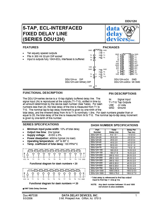
SERIES SPECIFICATIONS
• • • • • • Minimum input pulse width: 10% of total delay Output rise time: 2ns typical Supply voltage: -5VDC ± 5% Power dissipation: 400mw typical (no load) Operating temperature: -30° to 85° C Temp. coefficient of total delay: 100 PPM/°C
24 23 22 21
.400 TYP.
1 3 4 5 8 9 11 12 16
1.650 TYP.
.020 .320 TYP. MAX. .150 ±.030 .100 .200 .300 .400 .700 .800 .900 1.000 1.100 .075 1.500 .018 TYP.
.012 TYP. .300 TYP.
Doc #97036
5/3/2006
DATA DELAY DEVICES, INC.
Tel: 973-773-2299 Fax: 973-773-9672
2
元器件交易网
DDU12H
PACKAGE DIMENSIONS
32 31 9 11 12 24 23 22 21 GND T6 T8 T10
GND T1 T3 T5 N/C N/C GND N/C N/C T6 T8 T10
DDU12H-xx DIP DDU12H-xxM Military DIP
VEE 16
DDU12H-xxC4 SMD DDU12H-xxMC4 Mil SMD
EN12451(中文1译文)

EN12450«无缝铜及其合金毛细圆管»
EN12452«热交换器用轧制、翅片、无缝铜及其合金管»
EN12735-1«空调及制冷用无缝圆及其合金铜管»第一部分:管道用管材
EN12735-2«空调及制冷用无缝铜及其合金铜管»第二部分:设备用管材
prEN13348«医疗气体用无缝铜及其合金铜管»
4.1.3编号
材料编号标识规定按EN1412标准进行。
4.2状态
本标准中,材料的状态标识规定按EN1173标准进行,分别如下:
R***:用R后面跟“***”(代表产品的最小抗拉强度值)来表示材料强度方面的要求。
H***:用H后面跟“***”(代表产品的最小硬度值)来表示材料硬度方面的要求。
注:产品“H***”可以用维氏硬度值来表示,也可以用布氏硬度值来表示。两种硬度试验方法均可以用标识“H***”来加以表示。
j)是否需要通过抗应力腐蚀试验(见6.5.2);
k)硬态管的两端管头是否需要退火处理;
l)如果管材需进行探伤检验(见6.5.4),则除非检验方法与评判准则由买方选定,否则探伤检验方法见条款8.5;
m)管材是否用于焊接场合(见表1);
n)是否需要一致性声明文件(见9.1);
o)是否需要检验文件,如果需要,哪种类型(见9.2);
EN12451
(译文)
热交换器用无缝铜及其合金圆管
本欧洲标准于1999年6月14日由CEN批准实施。
CEN成员应遵守CEN/CENLEC内部规则,该规则规定了各CEN成员不准更改本欧洲标准直接成为国家标准的条件。
关于各成员国此类最新的国家标准文献目录可以从CEN管理中心或各CEN成员国获得。
聚烯烃类低烟无卤介绍

低烟无卤料内在性能的介绍
烟密度(有焰
无焰) 卤酸释放量(≤5 mg/g ) pH值≥4.3 电导率(≤10 μS/mm) 毒性指数≤5
与其他电缆料性能上的差异
拉伸强度和断裂伸长率均较PVC和PE低; 氧指数高于一般PVC料,但实际阻燃性
能不如PVC,自熄性差; 填充大量阻燃剂,密度较高;
聚烯烃类(低烟无卤)介绍
2011.08.10
无卤低烟阻燃聚烯烃料的特点
环保:不含卤素(氟氯溴碘)、重金属(铅镉
汞锑砷钡铬)、多溴联苯和多溴联苯醚等
燃烧时无卤酸气体放出,毒性和腐蚀性气体释
放量极少,产生的烟雾浓度极低 ,满足透光 率要求
低烟无卤聚烯烃料的应用场合
适用于阻燃要求高、二次危害小的场合
无卤料加工过程中的常见问题与解决方法
现象:挤出时电缆外径波动 可能原因:a.挤塑机出料不稳定;
b.牵引不稳定; c.缆芯外径波动。 解决方法: A. 主机电流和挤线速度允许的情况下降低挤塑机温度,或增加 滤网、分流板,使材料在机筒内获得足够、稳定的推力; B.检查配模,选择合理的模芯、模套配合; C.对不稳定的牵引系统维修; D.控制前道工序半制品外径。
低烟无卤料内在性能的介绍
体积电阻率 (Ω.m)
护套≥1.0*1010 绝缘≥5.0*1011
密度(g/cm3 )
一般在1.45左右
氧指数(≥30%) 一般在35左右
低烟无卤聚烯烃料的燃烧性能
单根垂直燃烧试验
(IEC 60332-1和-2) (GB/T 18380.1和.2) 与UL中VW-1的区别(要求更严格)
无卤料加工过程中的常见问题与解决方法
现象:机械性能偏低(抗张强度、断裂伸长率) 可能原因:
CEI122-150MB资料

OUTLINE /CEI1221.2µH – 22µH ± 20% (M)0.7µH – 15µH ± 20% (M)/ その他Other *IV Temperature Rise Current (Typ.) : The actual current when temperature of coil becomes∆T=40°C. (Ta=20*IV温度上昇実力電流:直流電流を流した時、コイルの温度上昇がΔT=40℃となる電流の実力値°C)°C)nominal value.(Ta=20 とする。
(Ta=20℃)*B 直流重畳許容電流:直流重畳許容電流を流した時、インダクタンスが公称インダクタンスの75%以*B Saturation Rated Current : The current when the inductance becomes 25% lower than its上となる電流値とする。
(Ta=20℃)( 0.7µH - 22µH )概要By using the square wire, power inductors can be used for large currents with low profile and low resistance.平角線を使用する事により、薄形・低抵抗で大電流対応を実現しました。
/ インダクタンス公差/ インダクタンス測定周波数(L)100kHz 100kHzMeasuring Freq. (L)Tolerance of Inductance CEI122(S)CEI122(H)CEI122(S)/ 無鉛製品についてAbout Lead-free products .Lead-free products are now available for sale.To order a lead-free product, please add"NP" after the product type:無鉛製品は現在、販売されております。
瑞士制造 系列 混凝土耐久性电阻率检测一体化解决方案 高级 Resipod 系列说明书
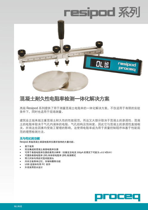
混凝土耐久性电阻率检测一体化解决方案可在不同的天数重复检测,如 28 天、56天同一圆柱还可用抗压强度检测带有 1.5” (38mm) 探头间距的 Resipod 完全符合上述标准Resipod 几何体 (SR)AASHTO T 358标准仅限用于最大聚体粒径为何体。
Resipod 几何体设计符合最新研究,旨在打破现行AASHTO标准的局限。
Resipod 几何体附带提供有可用于更大聚体粒径的可变间距探头。
这还可让用户通过 ResipodLink 软件输入几何校正系数,以直接在仪器上给出正确的电阻率读数。
ResipodLink 软件技术信息系统需求: Windows XP、Windows Vista、Windows 7、Windows 8、USB 连接器。
自动软更新需要用)。
固件更新(使用 PqUpgrade)需要 Internet 连接(如可用)。
需要 PDF Reader 显示“帮助手册”。
81038102C ver 12 2017 © Proceq SA ,瑞士。
版权所有。
总部 Proceq SA Ringstrasse 2 CH-8603 Schwerzenbach瑞士电话: +41 (0)43 355 38 00传真: +41 (0)43 355 38 12info@ 如有更改,恕不另行通知。
Proceq SA 出于善意提供本文档的所有信息,并相信这些信息正确无误。
对于信息的完整性和准确性,Proceq SA 不做任何担保,也不承担任何责任。
对于 Proceq SA 所生产和(或)销售的任何产品的使用和应用,我们已对特定的适用操作给予了明确的参考指引。
Resipod 技术信息电阻率测量测程1 – 约 1000 k Ωcm (取决于探头间距)分辨率(额定电流 200µA )±0.2 k Ωcm 或 ±1%(取二者中的较大值)分辨率(额定电流 50µA )±0.3 k Ωcm 或 ±2%(取二者中的较大值)分辨率(额定电流小于 50µA )±2 k Ωcm 或 ±5%(取二者中的较大值)显示3½ 数显频率40 Hz AC 内存非易失,约 500 个测量值电源>50 小时续航时间充电器连接B 型 USB 类型 (5V , 100mA)尺寸197 x 53 x 69.7 mm (7.8 x 2.1 x 2.7 inch )重量318g (11.2 oz)操作温度0° 到 50°C (32° 到 122°F )存储温度-10° 到 70°C (14° 到 158°F )订购信息组件描述381 10 000Resipod ,50mm 探头间距,检测板,泡沫垫,充电器和 USB 线缆,软件,背带,文档和盒子。
2015年CCC认证
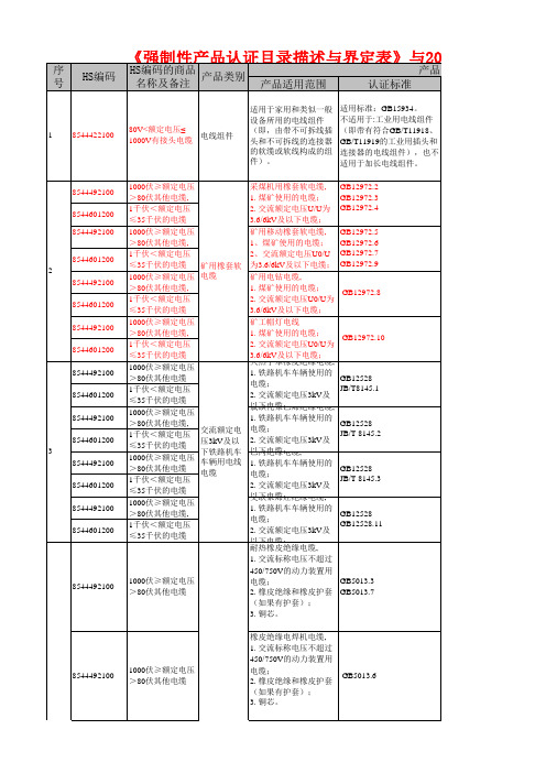
动机电路中的开关、隔离器、隔离开关和熔断器组合电器。
(隔离器、隔离开关、熔断器组合电器)(例如短路),能在规定时间内承载电流的一种机械开关电器。
适用于额定电压交流不超过GB14048.3测速发电机、感应移相器等);注3:不适用于有一种定额超出以上适用范围的多电压、多转速电动机。
1. 用手握持操作的,装有电源线并内装电源开关的、由电动机或由电磁铁作动力来驱动的;2. 额定电压大于50V 但不超过440V,电源频率GB14711速×1.1 kW/1500;注2:不包括防爆电动机和控制电动机(如伺服电动机、步进电动机、自和食品冷冻箱的,包括在商店、办公场所、酒店、轻工业、农场等场所由非电专业人员使用的;2. 单相器具额定电压不GB4706.13GB4343.1GB17625.1行放大的独立设备。
1于60ppm 的打印机。
用的打印设备、票据或照片等。
不在CCC 认证范围内的产品:1.光盘、服装、塑料件105汽车:在公路及城市道路上行驶的M、N、O类车辆1.在中国公路及城市道路上行驶的M类汽车、N类汽车和O类挂车(包括完整的和不完整的;不适用于在轨道上行驶的车辆、农业与林业用拖拉机和各种工程机械以及其它非道路车辆和三类底盘)1、车辆分类应符合GB15089-2001标准规定。
2、车辆定义应符合GB/T3730.1-2001标准规定。
3、专用车辆定义应符合GB/T17350-1998标准的规定。
4不包括三类底盘:只缺少车身或驾驶室、货箱(车厢)的汽车。
不包括三轮农用运输车:最高设计车速不大于50km/h,最大设计总质量不大于200Okg,长不大于4.6m、宽不大于1.6m,高不大于2m的三个车轮的货车。
不包括四轮农用运输车:最高设计车速不大于70km/h,最大设计总质量不大于4500kg,长小于6m、宽不大于2m,高不大于2.5m的四个车轮的货车。
不包括无轨电车。
高设计车速不大于20km/h的电驱动的两轮车辆。
CVTC 22001-2015 汽车零件和材料 禁限用物质要求介绍
CVTC 22001-2015
汽车零件和材料 禁限用物质要求
1 范围
本标准规定了汽车零件和材料中禁限用物质的管控要求、检测方法及合规判定等。 本标准适用于上汽商用车技术中心(CVTC)开发设计的车辆以及这些车辆上的全部零件和材 料,也可以参考应用于售后服务所需的零件和材料。 本标准不适用于在车辆以及其零件在制造过程中所消耗的零件和材料(如切削油、清洁液、 遮蔽胶带等)。
4 内部资料,注意保密
CVTC 22001-2015
附录A (规范性附录)
物质豁免表
材料及零部件 合金元素的铅
表 A.1 零件及材料中禁限用零件及材料中禁限用物质豁免表
豁免范围和期限
1. 机械加工用钢材和镀锌钢(铅≤0.35%)
2. 铝材(铅≤0.4%)
3. 铜合金(铅≤4%)
4(a). 轴瓦和轴套
汽车零件和材料中不能含有石棉。
4.1.2 B类禁限用物质
正常使用时长期与人体接触的材料及轮胎中苯并[a]芘的质量百分数不得超过0.0001%,18种 多环芳烃(PAHs)之和不得超过0.001%。18种PAHs清单见附录C.1表格。
汽车及其零部件产品中每一种均质材料中的全氟辛烷磺酸(PFOS)的质量分数不得超过0.1%, 纺织品或涂料中PFOS的质量分数不得超过1μ g/m3。
a) 采用 QC/T 942 的 4 的点滴法和沸水萃取法进行定性测试,如果检测结果是阴性,判为 合格;如果检测结果是阳性,则需进行定量测试。 b) 采用 QC/T 942 的 5 的比色法进行定量测试,结果>0.1μ g/cm3,样品中含有 Cr6+,判 定为不合格;结果≤0.1μ g/cm3,样品中不含 Cr6+,判定为合格。 6.2.2 铅、汞、镉、多溴联苯和多溴联苯醚的判定 汽车零件和材料中检测出的铅、汞、镉、六价铬、多溴联苯和多溴联苯醚满足附录 B 表 B.3 的要求,则判定为合格;如果任意一均质材料禁用物质超标,则零件判为不合格。 6.3 石棉检测结果的判定 检测单元中定性和定量均未检出石棉,同时满足表 B.1 和 B.3 的要求,则判定零件或材料为 合格;任意一检测单元检测出石棉材料,则零件或材料判定为不合格。
cei 标准

cei 标准
CEI标准是意大利电工委员会(Comitato Elettrotecnico Italiano)制定的关于电工、电子和电信领域的技术标准化。
它是一个非营利的私人协会,在国家层面运营,致力于电工、电子和电信领域的技术标准化。
CEI标准主要涉及电缆在火灾条件下的测试方法,特别是在建筑、交通运输、电力系统等领域。
其中,CEI EN 50265-1标准是电缆行业的国际标准,旨在评估电缆在火灾条件下的性能。
该标准主要关注电缆绝缘导体的耐火焰垂直传播试验,以确保电缆在火灾情况下不会促使火势蔓延,降低火灾的危险性。
CEI标准的制定和发布有助于提高电缆材料的耐火性能,减少火灾对人员和财产的威胁,同时推动了更安全、更可持续的建筑和电力系统的设计和生产。
此外,这些标准也是响应市场表达的特定需求而诞生的,以在国家或国际层面共享参考。
总之,CEI标准在电工、电子和电信领域的技术标准化方面发挥着重要作用,对于提高产品质量、保障安全、促进可持续发展具有重要意义。
MA122中文资料

Symbol VR VRM IF IFM IFSM Tj Tstg
Rating 80 80 100 225 500 150 −55 to +150
Unit V V mA mA mA °C °C
1 : Cathode 1 4 : Cathode 3 2 : Cathode 2 5 : Cathode 4 3 : Anode 3,4 6 : Anode 1,2 Mini Type Package (6-pin)
Reverse voltage VR (V)
Pulse width tW (ms)
2
Note) 1. Rated input/output frequency: 100 MHz 2. * : trr measuring circuit
Bias Application Unit N-50BU tr 10% Input Pulse tp t IF trr t Irr = 0.1 · IR IF = 10 mA VR = 6 V RL = 100 Ω Output Pulse
5
4
10−2
3
10−3
2
10−4
1
10−5 −40
0
0 40 80 120 160 200 240
Forward surge current IF(surge) (A)
Reverse current IR (µA)
0
20
40
60
80
100
120
0.1
0.3
1
3
10
30
Ambient temperature Ta (°C)
IR Ta
10 VR = 75 V 1 35 V
法国溯高美低压产品介绍
熔断器开关 Fuserbloc 32 – 1250 A
• Fuserbloc 32 – 1250 A
主要特点:
• 模块化设计,每极1个模块 • 63A 以下导轨固定 • IP2 (熔断器盖和端子盖) • 试验位子为标准配置 ( 400A以下 ) • 1 至 21 极 • 直接操作 • 正面柜外操作 • 侧面操作 (左侧和右侧) • 可设置辅助触点 • 熔断指示 • 背面连接
正常 / 应急控制 器
ATyS 6
ATyS 3
ATyS C20/C30/C40
SWITCHING RANGE GB 10/2005
ATyS 系列电流等级
ATyS 3:
ATyS 3s : 125 – 1800A,3P/4P 10个电流等级 ATyS 3e : 2000 – 3200A,3P/4P 3个电流等级
SWITCHING RANGE GB 10/2005
熔断器开关 Fuserbloc CD 25 – 32 A
Disconnectable Neutral
GB/DIN:
25A 和 32A (熔断器尺寸: 10x38 和 14x51) 3 极和 3极+ 开关或固定中心极
附件:
• 直接和柜外手柄 • 可断开中性极 • 熔断器熔断指示( DIN 尺寸14x51) • U 型辅助触点模块 • 模块化辅助触模块 • 2x2 可设置 U 型辅助触点
SWITCHING RANGE GB 10/2005
熔断器开关
FUSERBLOC 系列 25 – 1250 A
SWITCHING RANGE GB 10/2005
熔断器开关 Fuserbloc CD 25 – 32 A
IT120资料
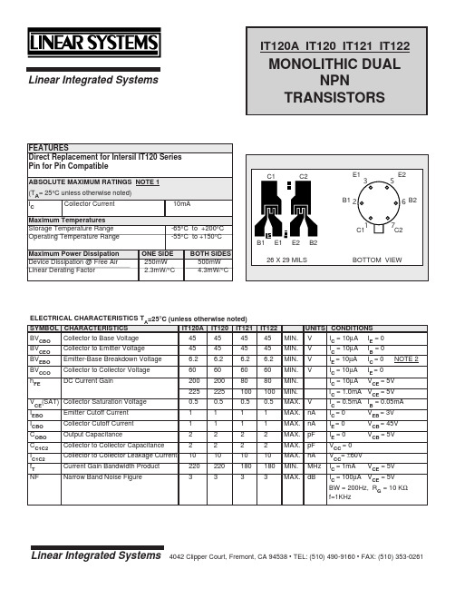
P-DIP
0.320 (8.13) 0.290 (7.37) 0.405 (10.29) MAX. C1 B1 E1 N/C 1 2 3 4 8 7 6 5 C2 B2 E2 N/C
0.016 0.019 DIM. A 0.016 0.021 DIM. B 0.029 0.045
IT122 45 MIN. 45 6.2 60 80 100 0.5 1 1 2 2 10 180 3 MIN. MIN. MIN. MIN. MIN. MAX. MAX. MAX. MAX. MAX. MAX. MIN. MAX.
UNITS CONDITIONS V IC = 10µA IE = 0 V V V IC = 10µA IE = 10µA IC = 10µA IC = 10µA V nA nA pF pF nA MHz dB IB = 0 IC = 0 IE = 0 VCE = 5V NOTE 2
C1 B1 E1 N/C
1 2 3 4
8 7 6 5
C2 B2 E2 N/C
0.228 (5.79) 0.244 (6.20)
NOTES:
1. These ratings are limiting values above which the serviceability of any semiconductor may be impaired. 2. The reverse base-to-emitter voltage must never exceed 6.2 volts; the reverse base-to-emitter current must never exceed 10 µA.
-65°C to +200°C -55°C to +150°C B1 ONE SIDE 250mW 2.3mW/°C BOTH SIDES 500mW 4.3mW/°C E1 E2 B2
mc2中文说明书

安全性
MC2 可以经受工业环境的考验,具有很好的防震功能。它十分精密灵
武汉联合约克仪器有限公司 编译
7
York instrument LTD
巧,对使用者的技术要求比较高。而且必须对操作手册有个好的理解。 尽量避开电磁信号源,以免影响到测量精度。 可充电电池在充电的过程中会发出少许气体,这种气体是易爆的,虽
要有超过 60V 直流、30V 交流和 100mA 的电信号。 MC2 最大输出电压低于 30V,所以输入、输出的时候千万小心。
废弃电池与材料的处理 贝美克斯很注重对环境的保护,他设计的产品很容易回收利用而不污
染环境。 欧盟和其他国家联合建立了一个体系——WEEE。WEEE/EC 要 求所有生产电器电表的厂家对产品的回收和循环利用负责。这一政策在 2005 年 8 月在欧洲市场实施。旨在保护环境、保护人类身体和维持自然资
源。标签上引有
符号的,表示可再回收利用。
建议 不要随便打开 MC2 外壳。只有具备资格的专业技术人员才能维修。 充电器不能维修,请依据环保法规妥善处理废弃的充电器。 若重新设置 MC2,同时按下回车键和开关键 5 秒钟。然后再次按下开
关键即可。重设后 MC2 的时钟回到 1970 年 1 月 1 日 0 点。记得输入正确 的时间。不建议重设。详细可咨询武汉约克仪器公司。 若清洁 MC2,用软布沾些清洁油擦拭。过几分钟,再用湿布擦干。
武汉联合约克仪器有限公司 编译
10
内部压力模块(IPM)
York instrument LTD
压力模块类型:
·IPM200mC 量程:±200mbar(±20 kPa)
·IPM2C 量程:-1 ̄+2bar(-100 ̄+200 kPa)
西电控制器中文说明
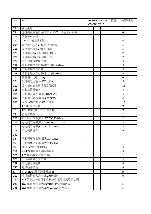
Decmber 2000 - issue 1MICS TelysAlarm and fault messages目录1 - 导言2 - CB, CB1, CB12板共有的信息3 - CB1 and CB12板共有的信息4 - CB12板专有的信息5 - 模块3专有的信息6 - 模块4专有的信息e7 - 模块5专有的信息8 - 模块6专有的信息出版日期1 December 2000报警及故障信息- MICS TelysDecember 2000 - 第一版第一页/共五页1 - 导言下面的表格用于帮助用户了解显示在MICS Telys屏幕上的报警及故障信息。
It is understood that if a fault or alarm is displayed on the CB12 interface board, it will not necessarily bedisplayed on the CB interface board (例如: Fault oil temp.).提示:- 当故障发生时,机组立即卸载(仅在自动Auto模式下)并且立即或者延时停机,具体情况由Delays延时菜单中的设定来决定。
- 当报警发生时,发动机不停机。
- 报警或者故障的选择,在Option选项菜单中设定。
- 任何故障都会引起« general fault »综合故障指示灯(红)闪烁。
- 任何报警都会引起« general alarm »综合报警指示灯(黄)闪烁。
2 - CB, CB1, CB12板共有的信息3 - CB1 and CB12板共有的信息4 - CB12板专有的信息5 - 模块3板专有的信息屏幕显示反应时间描述Fault mainsWaterFlow 立即主水源(用于冷却)故障Fault fireDetection 立即发电机房火警Fault oil Leak 立即机油箱泄漏Fault fuel Leak 立即储油罐泄漏Fault A/C Door Open 立即空气冷却器厢门打开(仅在集装箱)Fault MCPSDoor Open 立即MCPS厢门打开(仅在集装箱)Fault C/B OpenAlarm C/B Open 立即发电机组电路断路器处于断开位置6 - 模块4板专有的信息提示:模块4用于特殊的场合,它可以通过键盘,在第三级菜单中编程。
122系列- 选型手册说明书

Selection conditions differ from the general air cylinder. Check the suitability with the selection guide.Step2Confirm working conditions1. Working pressure P (MPa)2. Load weight W (N)<Load weight>Consider the weight of the cylinder's guide rodwhen determining load weight.W = (load weight) + (jig weight) +(guide rod's weight: a) value.Calculate the guide rod's weight with calculationformulas in Table 1.Table 1 Guide rod weight calculation formula3. Installation direction<Operation method>Horizontal, vertical - rise, vertical - lower4. Stroke L (mm)5. Operation time t (s)6. Operation speed V (mm/s)Cylinder average operation speed Va calculation formula Va = L/t (mm/s)Step3Select the approximate cylinder sizeCylinder size (inner bore) calculation formulaF= /4 X D2D= 4F/ PD: Cylinder bore size (mm)P: working pressure (MPa)F: Cylinder's theoretical thrust (N)Obtaining with the theoretical thrustApproximate required thrust load weight x 2( x 2 in the load weight x 2 is whenthe load is 50% as the safety coefficient)<Example> Working pressure 0.5 (MPa)Load 25 (N)Required thrust is:25 (N) x 2=50 (N)Based on Table 2, the tube diameteris 12 and over to satisfy a theoreticalthrust of 50N and over at a workingpressure of 0.5MPa.D = 12st: Stroke length (mm)122123Step4Step4Calculating the weight (W) and each momentCalculate the static load (W 0) and moment (M) based on how the load is installed on the cylinder. W 0 = (load) + (jig weight) (N) M 1 = F 1 X 1 (N m) M 2 = F 2 X 2 (N m) M 3 = F 3 X 3 (N m) Use Fig. 2 for the F 1, F 2 and F 3 values Fig. 2 Moment calculation formulaCalculate each moment from the load, inertia force coefficient and eccentricity length.<Twisting moment>M 3 = F 3 X 3=10 X m 3 X 3<Bending moment>M 1 = F 1 X 1<Radial moment>M 2 = F 2 X 2 = 10 X m 2 X G X 2m 1:m 2:m 3:Load (N)3:2:1:Eccentricity distance (m) G :Inertia force coefficientFig. 3 Trends of moment of inertia coefficient for guided cylinder 13Selection guide124Step5Confirm load and movement based on operation direction*Refer to Page 126 for allowable lateral load.The load is determined based on use such as stability of the cylinder's operation speed, allowance, and life. General use should be within the range in Table 3.Lateral load functions during an eccentric load. The functioning lateral load must be less than the allowable lateral load in Table 2.Wmax 5-1 Confirm loadDuring horizontal operation The static load must be less than the allowable load Static load W 0 Value calculated in Step 4Allowable lateral load Wmax Select from Table2 based on the stroke (For the custom stroke length, select the longer standard stroke) W 0 WmaxTable 2 Allowable lateral load1During vertical operationThe load weight must be a value that applies the load in theoretical thrust Calculating the load Load WValue calculated in Step 2 Cylinder's theoretical thrust F = W/F X 100 (%)2Divide the bending moment and radial moment with the value in Table 4, and obtain the moment. The total moment must be 1.0 or less. Calculating the moment Bending moment M 1 Radial moment M 2M 1/M 1 max + M 2/M 2max 1.0Value calculatedin Step 45-2. Confirm moment11Selection guideTable 4 Allowable moment (N m)* Refer to page 126 for the allowable rotation torque.Table 6 STS and STL allowable energy absorption (E1)The value of the kinetic energy absorption performance providedby the cylinder's cushion mechanism differs based on the cylinder'sbore size.This energy is comparable to the values in Table 6 forthe guided cylinder.Confirm that the kinetic energy of the loadactually being used is absorbed by the cylinder'sown cushion performance.Allowable energy absorption of cylinder(E1) is unique to the cylinder. The values inTable 7 are used for STS and STL.Piston's kinetic energy (E2) calculation formulaW: load (N) Value calculated in Step 2V: Piston cushion rush speed (m/s)V=L/t X (1+1.5 X /100)L: Stroke length (m)T: Operation time (s): Load (%)E2=1/2 X W X V2 X (J)Cylinder's allowable energy absorption(Allowable energy absorption) > (Piston's kinetic energy)E1 > E2(Allowable energy absorption) < (Piston's kinetic energy)E1 < E2End of selectionThe twisting moment must be less than thetolerable rotation torqueTwisting moment M3 Value calculated inStep 4 Allowable rotation torqueM3max Select from Table 5 based on stroke length.(For a custom stroke length, select the longer standard stroke)M3 M3maxTable 5 Allowable rotation torque (N m)2101125。
ACE12022VM资料
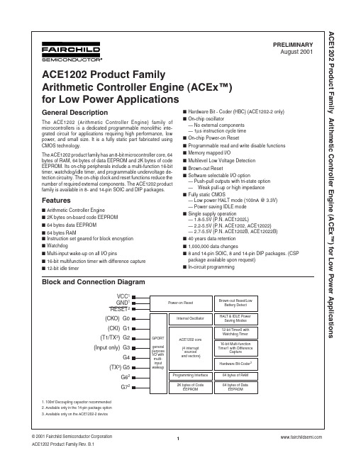
ACE1202 Product Family Arithmetic Controller Engine (ACEx™) for Low Power ApplicationsACE1202 Product Family Arithmetic Controller Engine (ACEx™) for Low Power ApplicationsACE1202 Product Family Arithmetic Controller Engine (ACEx™) for Low Power ApplicationsF r e q u e n c y (M H z )Temperature [°C]Temperature [°C]ACE1202 Product Family Arithmetic Controller Engine (ACEx™) for Low Power Applications I c c I D L E(µA)IDLE current vs. Temperature Temperature [°C]ACE1202 Product Family Arithmetic Controller Engine (ACEx™) for Low Power ApplicationsACE1202 Product Family Arithmetic Controller Engine (ACEx™) for Low Power ApplicationsACE1202 Product Family Arithmetic Controller Engine (ACEx™) for Low Power ApplicationsACE1202 Product Family Arithmetic Controller Engine (ACEx™) for Low Power ApplicationsACE1202 Product Family Arithmetic Controller Engine (ACEx™) for Low Power ApplicationsACE1202 Product Family Arithmetic Controller Engine (ACEx™) for Low Power ApplicationsACE1202 Product Family Arithmetic Controller Engine (ACEx™) for Low Power ApplicationsACE1202 Product Family Arithmetic Controller Engine (ACEx™) for Low Power ApplicationsACE1202 Product Family Arithmetic Controller Engine (ACEx™) for Low Power ApplicationsACE1202 Product Family Arithmetic Controller Engine (ACEx™) for Low Power ApplicationsACE1202 Product Family Arithmetic Controller Engine (ACEx™) for Low Power Applicationsinto the decision register is 1, the pattern in the HPATTERN register is shifted out of the output port. Similarly, if the active bit is 0 the pattern in the LPATTERN register is shifted out.The HBC control (HBCNTRL) register is used to configure and control the data transmission. HBCNTRL is divided in 5 different controlling signal FRAME[2:0], IOSEL, TXBUSY, START/STOP, and OCFLAG (see Figure 23.)FRAME[2:0] selects the number of bits of DAT0 to encode and transmit. The HBC allows from 2 (0x1) to 8 (0x7) DAT0 bits to be encoded and transmitted. Upon a reset, FRAME is initialized to zero disabling the DAT0’s decision register transmitting no data. The IOSEL signal selects the transmission to output (TX) through either port G2 or G5. If IOSEL is 1, G5 is selected as the output port otherwise G2 is selected.The TXBUSY signal is read only and is used to inform software that a transmission is in progress. TXBUSY goes high when the encoded data begins to shift out of the output port and will remains high during each consecutive DAT0 frame bit transmission (see Figure 25). The HBC will clear the TXBUSY signal when the last DAT0 encoded bit of the frame is transmitted and the STOP signal is 0.The START / STOP signal controls the encoding and transmission process for each data frame. When software sets the START / STOP bit the D AT0 frame transmission process begins. The START signal will remain high until the beginning of the last encoded DAT0 frame bit transmission. The HBC then clears the START / STOP bit allowing software to either continue with a new DAT0 frame transmission or stop the transmission all together (see Figure 25). If TXBUSY is 0 when the START signal is enabled, a synchronization period occurs before any data is transmitted lasting the amount of time to transmit a 0 encoded bit (see Figure 24).The OCFLAG signal is read only and goes high when the last encoded bit of the D AT0 frame is transmitting. The OCFLAG signal is used to inform software that the D AT0 frame transmission operation is completing (see Figure 25). If multiple DAT0 frames are to be transmitted consecutively, software should poll the OCFLAG signal for a 1. Once OCFLAG is 1, DAT0 must be reload and the START / STOP bit must be restored to 1 in order to begin the new frame transmission without interruptions (the synchroni-zation period). Since OCFLAG remains high during the entire last encoded DAT0 frame bit transmission, software should wait for the HBC to clear the OCFLAG signal before polling for the new OCFLAG high pulse. If new data is not reloaded into D AT0 and the START signal (STOP is active) is not set before the OCFLAG is 0, the transmission process will end (TXBUSY is cleared) and a new process will begin starting with the synchronization period. Figure 24 and 25 shows how the HBC performs its data encoding. In the example, two frames are encoded and transmitted consecu-tively with the following bit encoding format specification:1.Transmission frequency = 62.5KHz2.Data to be encoded = 0x52, 0x92 (all 8-bits)3.Each bit should be encoded as a 3-bit binary value, ‘1’ =110b and ‘0’ = 100b4.Transmission output port : G2To perform the data transmission, software must first initialize the PSCALE, BPSEL, HPATTERN, LPATTERN, and DAT0 registers with the appropriate values.LD PSCALE, #03H; (1MHz ÷ 4) ÷ 4 = 62.5KHz LD BPSEL, #012H; BPH = 2, BPL = 2 (3 bits each) LD HPATTERN, #0C0H; HPATTERN = 0xC0LD LPATTERN, #090H; LPATTERN = 0x90LD DAT0, #052H; DAT0 = 0x52Once the basic registers are initialized, the HBC can be started. (At the same time, software must set the number of data bits per data frame and select the desired output port.)LD HBCNTRL, #27H;START / STOP = 1,FRAME = 7, IOSEL = 0ACE1202 Product Family Arithmetic Controller Engine (ACEx™) for Low Power Applications8.0Hardware Bit-Coder (ACE1202-2 only)The ACE1202-2 contains a dedicated hardware bit-encoding peripheral block, Hardware Bit-Coder (HBC), for IR/RF data transmission (see Figure 21.) The HBC is completely software programmable and can be configured to emulate various bit-encoding formats. The software developer has the freedom to encode each bit of data into a desired pattern and output the encoded data at the desired frequency through either the G2 or G5output (TX) ports.The HBC contains six 8-bit memory-mapped configuration regis-ters PSCALE, HPATTERN, LPATTERN, BPSEL, HBCNTRL, and D AT0. The registers are used to select the transmission fre-quency, store the data bit-encoding patterns, configure the data bit-pattern/frame lengths, and control the data transmission flow.To select the IR/RF transmission frequency, an 8-bit divide constant must be written into the IR/RF Pre-scalar (PSCALE)register. The IR/RF transmission frequency generator divides the1MHz instruction clock down by 4 and the PSCALE register is used to select the desired IR/RF frequency shift. Together, the transmission frequency range can be configured between 976Hz(PSCALE = 0xFF) and 125kHz (PSCALE = 0x01). Upon a reset,the PSCALE register is initialized to zero disabling the IR/RF transmission frequency generator. However, once the PSCALE register is programmed, the desired IR/RF frequency is main-tained as long as the device is powered.Once the transmission frequency is selected, the data bit-encod-ing patterns must be stored in the appropriate registers. The HBC contains two 8-bit bit-encoding pattern registers, High-pattern(HPATTERN) and Low-pattern (LPATTERN). The encoding pat-tern stored in the HPATTERN register is transmitted when the data bit value to be encoded is a 1. Similarly, the pattern stored in the LPATTERN register is transmitted when the data bit value to be encoded is a 0. The HBC transmits each encoded pattern MSB first.The number of bits transmitted from the HPATTERN and LPATTERN registers is software programmable through the Bit Period Configuration (BPSEL) register (see Figure 22). D uring the transmission of HPATTERN, the number of bits transmitted is configured by BPH[2:0] (BPSEL[2:0]) while BPL[2:0] (BPSEL[5:3])configures the number of transmitted bits for the LPATTERN. The HBC allows from 2 (0x1) to 8 (0x7) encoding pattern bits to be transmitted from each register. Upon a reset, BPSEL is initially 0disabling the HBC from transmitting pattern bits from either register.The Data (DAT0) register is used to store up to 8 bits of data to be encoded and transmitted by the HBC. This data is shifted, bit by bit, MSB to LSB into a 1-bit decision register. If the active bit shiftedACE1202 Product Family Arithmetic Controller Engine (ACEx™) for Low Power ApplicationsACE1202 Product Family Arithmetic Controller Engine (ACEx™) for Low Power ApplicationsACE1202 Product Family Arithmetic Controller Engine (ACEx™) for Low Power ApplicationsACE1202 Product Family Arithmetic Controller Engine (ACEx™) for Low Power ApplicationsACE1202 Product Family Arithmetic Controller Engine (ACEx™) for Low Power ApplicationsACE1202 Product Family Arithmetic Controller Engine (ACEx™) for Low Power ApplicationsACE1202 Product Family Arithmetic Controller Engine (ACEx™) for Low Power ApplicationsACE1202 Product Family Arithmetic Controller Engine (ACEx™) for Low Power ApplicationsACE1202 Product Family Arithmetic Controller Engine (ACEx™) for Low Power Applications14-Pin DIP (N14)Order Number ACE1202(12022, 1202L)N14/ACE1202(12022)EN14/ACE1202VN14 ACE1202(12022)BN14/ACE1202(12022)BEN14/ACE1202(12022)BVN14Package Number N14AACE1202 Product Family Arithmetic Controller Engine (ACEx™) for Low Power Applications。
TIP122中文资料_数据手册_参数
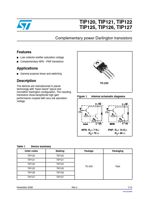
hFE
1000 100
Tj= -40 °C Tj= 25 °C Tj=125 °C
VCE= 3 V
1000 100
Tj= -40 °C Tj= 25 °C Tj=125 °C
VCE= -3 V
10
0.01
0.1
1
Ic(A)
10
-0.01
-0.1
-1
Ic(A)
Figure 6. Collector-emitter saturation voltage Figure 7. Collector-emitter saturation voltage
TIP120, TIP121, TIP122 TIP125, TIP126, TIP127
Complementary power Darlington transistors
Features
■ Low collector-emitter saturation voltage ■ Complementary NPN - PNP transistors
Table 4. Electrical characteristics(1)
Symbol
Parameter
Test conditions
Min. Typ. Max. Unit
ICEO
Collector cut-off current (IB = 0)
for TIP120/125 for TIP121/126 for TIP122/127
for NPN type
for PNP type
VCE(sat) (V)
hFE= 250 1.4
AM00698v1
VCE(sat) (V)
hFE= 250 -1.4
ASME A112.19.2-2003(中文)
一部美国国家标准美国ASME瓷质陶瓷管道设施以及座便器和小便器的水力要求ASME A112.19.2-2003对ASME A112.19.2M-1998和ASME A112.19.6-1995的修订和合并颁布日期2004年6月15日目录前言标准委员会花名册与A112 委员会的通讯1.总则2.瓷质卫生陶瓷要求3.尺寸要求4.冲洗装置5.性能要求6.标志和安装说明7.瓷质卫生陶瓷和其他材料的测试8.座便器测试9.洗脸盆溢水测试10.小便器的测试图形和数据1.座箱式下排水座便器的典型排污口2.后排水和Rear-Spigot-Outlet 座便器的典型排污口详细资料3.壁挂式座便器螺丝孔间距4.上按钮下排式座便器的坑距和盖板螺栓要求5.后按钮下排式座便器的坑距和盖板螺栓要求6.洗面器和净身器进水孔和出水孔的详细资料7.分体座便器和壁挂式座便器重力型水箱8.检测座便器重力型水箱和座便器冲水型水箱必须的供水标准9.检测座便器和小便器冲水阀的必须的供水标准10.座便器和小便器水封深度建议器械图解11.排水管道传输特性的测试工具组合表格1.瓷质卫生陶瓷座便器,水箱和小便器的最大误差允许范围2.瓷质卫生陶瓷洗面器和自动饮水器的最大误差允许范围3.小便器的标准尺寸和水道4.小便器的最小尺寸5.座便器水力性能测试的静压力测试6.小便器实验室的静压力测试非强制性要求附录A 对ASME A112.19.2 的遵从展示B 图例C 政府要求D 测试结果报告的建议格式E 测试材料F 补充购买规格:低耗水型座便器排放调节要求美国ASME瓷质陶瓷管道设施以及座便器和小便器的水力要求1.总则1.1 范围这个标准设立了对于卫生陶瓷管道设施的要求和测试方法,包括材料,尺寸,功能。
卫生性能要求和测试过程适用于所有座便器、小便器通过重力排污系统,在永久性建筑和结构,独立的占用。
在这个标准里提到的设施包括:座便器、洗面器小便器、净身器、水槽、自动饮水器,和构造性实用设施。
铝合金电缆C222No51-09加拿大标准3
铝合金电缆C222No51-09加拿大标准3加拿大标准C22.2 No. 51-09 铠装电缆内容配线产品技术委员会 V金属复合电缆综合委员会 VII前言 VIII(1)适用范围 1(2)参考出版物 1(3)定义 3(4)一般要求 3(5)结构35.1 导体35.1.1 一般说明35.1.2 铝导体45.1.3 铜导体45.1.4 尺寸规格45.1.5 绞合45.1.6 直径和截面55.1.7 接头55.1.8 中性导体55.2 绝缘55.3 组装成缆55.4 导体的颜色编码65.4.1 多芯电缆芯线导体65.4.2 单导体电缆只用于接合用途75.5 铠装75.5.1 AC90和ACWU90类型的75.5.2 ACG90和ACGWU90类型75.6 带护套的ACWU90 和 ACGWU90类型电缆75.7 其他电缆组件6 测试76.1 裸导体性能测试76.1.1 电阻6.1.2 铝导体的拉伸强度和断裂伸长率86.1.3 铝导体弯曲试验86.1.4 高电流热循环 - ACM规格为12和10AWG 实心导体,以及12至2AWG ,B类绞合导体6.2 绝缘导线性能测试86.2.1 物理测试 86.2.2 电气测试 116.3 铠装性能测试136.3.1 保护镀层钢带136.3.2 内表面136.4.1 切割146.4.2 物理性能147标识217.1 成品标记217.1.1 铝导体217.1.2 AC90型和 ACG90型217.1.3 ACWU90型和ACGWU90型217.2 在线圈和卷轴上的标识21附件A(规范性附录) - ACM识别化学成分 41表格1 - 导体直径和横截面积222A - 最大直流电阻在20°C的,实心铝线,裸铜线,有镀层铜导体242B - 最大直流电阻在20°C的,铝和裸铜导体 - 同心绞合B,C,D类;紧密绞线,压缩绞合,组合单位式* 242C - 最大直流电阻的铜导体,同心绞合线和在20℃下,压缩绞合B类,C类,和D的每一条绞合镀层,和组合单位式*与每个绞合镀层262D - 最大直流电阻在20°C,G和H类多绞合导线282E - 最大直流电阻在20°C, M类绞合导线302F - 最大直流电阻在20°C的I类和K类绞合导线313 - 绝缘导线的颜色编码324 - 绝缘层厚度335 - 绝缘的最小切削力336 - 护套的最小切削力337 - 连接导体的最小尺寸348 - 多芯电缆最大节距369 - 铝导体的机械性能3710 - 变形试验负载3711 - 护套的物理性能3812 - 柔软性测试芯轴直径3813 - 绝缘的物理性质3814 - 测试电流和时间39图1 - 典型的短路装置的示意图392 - 铠装和任何所需的接地导体测量电阻的仪器393 - 电流测试使用的钢外壳404 - 电流测试采用钢外壳40接线产品技术委员会(人名,略)金属包层电缆综合委员会C22.2 No. 51-09铠装电缆1范围1.1本标准规定的要求,单和多芯绝缘电缆具有金属联锁铠装,没有整体外护套(AC90或ACG90型),或具有整体护套(ACWU90或ACGWU90型),用于安装在,按照加拿大电气标准,第I部分(Canadian Electrical Code,Part I,),额定电压为600 V及以下的系统上。
- 1、下载文档前请自行甄别文档内容的完整性,平台不提供额外的编辑、内容补充、找答案等附加服务。
- 2、"仅部分预览"的文档,不可在线预览部分如存在完整性等问题,可反馈申请退款(可完整预览的文档不适用该条件!)。
- 3、如文档侵犯您的权益,请联系客服反馈,我们会尽快为您处理(人工客服工作时间:9:00-18:30)。
OUTLINE /CEI122
1.2µH – 22µH ± 20% (M)0.7µH – 15µH ± 20% (M)
/ その他
Other *IV Temperature Rise Current (Typ.) : The actual current when temperature of coil becomes
∆T=40°C. (Ta=20*IV
温度上昇実力電流:直流電流を流した時、コイルの温度上昇がΔT=40℃となる電流の実力値°C)°C)
nominal value.(Ta=20 とする。
(Ta=20℃)
*B 直流重畳許容電流:直流重畳許容電流を流した時、インダクタンスが公称インダクタンスの75%以
*B Saturation Rated Current : The current when the inductance becomes 25% lower than its
上となる電流値とする。
(Ta=20℃)
( 0.7µH - 22µH )
概要
By using the square wire, power inductors can be used for large currents with low profile and low resistance.平角線を使用する事により、薄形・低抵抗で大電流対応を実現しました。
/ インダクタンス公差
/ インダクタンス測定周波数(L)
100kHz 100kHz
Measuring Freq. (L)Tolerance of Inductance CEI122(S)CEI122(H)
CEI122(S)/ 無鉛製品について
About Lead-free products .Lead-free products are now available for sale
.To order a lead-free product, please add"NP" after the product type:無鉛製品は現在、販売されております。
ご注文の際は製品タイプ名の後に”NP”をつけてください。
e.g. △△△○×
Ordering code of lead-free product: Type name NP △△△○×
..Ordering code of lead product: Type name-CEI122(H)
/ 品名表記法
Ordering Code CEI122 - -
: Parts No.
: Tolerance of inductance M (20%)
: Packing
C (Carrier tape) B (Box)
:
Nothing (Standard type) H (High power type)
Rev1.0 09/2004
North America
Tel:(1) 847 545-6700Fax:(1) 847 545-6720
E-mail: sales@ Japan
Tel:(81) 03 3667-3302Fax:(81) 03 3667-3408
Hong Kong
Tel:(852) 2880-6688Fax:(852) 2565-9600
E-mail: sales@ Taiwan
Tel:(886) 2 2726-2177Fax:(886) 2 2728-2726
E-mail: sales@ Singapore
Tel:(65) 6296-3388Fax:(65) 6296-3390
E-mail: sales@ Europe
Tel:(32) 2673-9565Fax:(32) 2672-0454
E-mail: sales@
E-mail: sales@。
