NRBT-8650蓄电池内阻测试仪参数概述
蓄电池内阻测试仪 产品说明书(V1.01)
蓄电池内阻测试仪产品说明书(V1.01)武汉启亦电气有限公司Wuhan Qiyi Electric Co.,Ltd本说明书对应蓄电池内阻测试仪,软件版本V1.01。
武汉启亦电气有限公司版权所有。
本说明书中的产品信息、技术参数代表说明书编写时的技术状态,更改恕不另行通知。
我们已经尽力确保本说明书中的信息可靠和准确,但仍可能存在不准确或者错误的地方。
使用说明尊敬的用户:感谢您购买本公司蓄电池内阻测试仪。
在您初次使用该产品前,请您详细地阅读本使用说明书,将可帮助您熟练地使用本仪器。
产品说明书是提供关于如何安全、正确和高效地使用蓄电池内阻测试仪的资料。
蓄电池内阻测试仪产品说明书包含使用该设备的重要安全说明,让您熟悉设备操作。
请阅读并遵循“安全规程”一节中所说明的安全规定以及所有相关的安装和运行说明。
遵从产品说明书里的指示有助于规避风险、减少修理费用及由于不正常操作导致的仪器故障。
应该在使用蓄电池内阻测试仪的现场常备产品说明书。
所有蓄电池内阻测试仪的操作者必须要阅读它。
除了遵守蓄电池内阻测试仪说明书的内容,您还要遵守在高电压电力设备上工作的所有相关的国家及国际安全规程。
在高压电力设备上工作是非常危险的。
使用蓄电池内阻测试仪进行的测量必须由具有相关资质的、熟练并经认可的人员来进行。
在工作开始前,请清晰地明确责任。
接受过蓄电池内阻测试仪训练、指导、培训的人员在从事高压电力设备的工作时,仍然需要有经验的操作员监督下进行。
安全规程:请阅读下列安全注意事项,以避免人身伤害!(1)在操作蓄电池内阻测试仪之前,请仔细阅读本章中的说明。
如果您不理解其中某些安全规程,在继续操作前请联系武汉启亦电气有限公司。
在使用蓄电池内阻测试仪工作时,要注意遵守安全规程。
(2)只有本公司专业技术人员或经认证的专业机构才能对蓄电池内阻测试仪进行维护和修理。
使用概述:(1)检查仪器本体及其附件完整无破损,尤其是要避免影响安全的损坏。
(2)做好免受相邻带电部分伤害的安全措施。
[AT520520SE交流低电阻测试仪][AT520LM电池内阻测试仪]
![[AT520520SE交流低电阻测试仪][AT520LM电池内阻测试仪]](https://img.taocdn.com/s3/m/774309fe162ded630b1c59eef8c75fbfc77d94cb.png)
[AT520/520SE交流低电阻测试仪] [AT520L/M电池内阻测试仪]用户手册AT520系列用户手册安全须知当你发现有以下不正常情形发生,请立即终止操作并断开电源线。
立刻与安柏科技销售部联系维修。
否则将会引起火灾或对操作者有潜在的触电危险。
●仪器操作异常。
●操作中仪器产生反常噪音、异味、烟或闪光。
●操作过程中,仪器产生高温或电击。
●电源线、电源开关或电源插座损坏。
●杂质或液体流入仪器。
安全信息为避免可能的电击和人身安全,请遵循以下指南进行操作。
免责声明用户在开始使用仪器前请仔细阅读以下安全信息,对于用户由于未遵守下列条款而造成的人身安全和财产损失,安柏科技将不承担任何责任。
为防止电击危险,请连接好电源地线不可在易燃易爆气体、蒸汽或多灰尘的环境使用仪器。
在此类环境使用任何电子设备,都是对人身安全的冒险。
非专业维护人员不可打开仪器外壳,以试图维修仪器。
仪器在关机后一段时间内仍存在未释放干净的电荷,这可能对人身造成电击危险。
如果仪器已经损害,其危险将不可预知。
请断开电源线,不可再使用,也不要试图自行维修。
如果仪器工作不正常,其危险不可预知,请断开电源线,不可再使用,也不要试图自行维修。
超出范围,仪器所提供的保护措施将失效。
声明:!$,标志和文字是常州安柏精密仪器有限公司已经或正在申请的商标。
目录有限担保和责任范围常州安柏精密仪器有限公司(以下简称Applent)保证您购买的每一台AT520/520SE/520L/520M在质量和计量上都是完全合格的。
此项保证不包括保险丝以及因疏忽、误用、污染、意外或非正常状况使用造成的损坏。
本项保证仅适用于原购买者,并且不可转让。
自发货之日起,Applent提供玖拾(90)天保换和叁年免费保修,此保证也包括VFD或LCD。
玖拾天保换期内由于使用者操作不当引起的损坏,保换条款终止。
叁年保修期内由于使用者操作不当而引起仪器损坏,维修费用由用户承担。
贰年后直到仪表终生,Applent将以收费方式提供维修。
蓄电池内阻对照表及影响因数

蓄电池内阻对照表及影响因数一、蓄电池内阻对照表A. 什么是蓄电池内阻蓄电池内阻是指蓄电池在充放电过程中产生的电阻。
它是一个重要的参数,可以反映蓄电池的性能和状态。
蓄电池内阻对照表是一种记录蓄电池内阻数值的表格,可以用来比较不同蓄电池的电阻值。
通过对比不同蓄电池的内阻数值,可以评估蓄电池的质量和性能,并选择合适的蓄电池应用于特定的场景。
蓄电池内阻对照表中的数据应该准确、全面,同时应该包含不同类型、不同规格的蓄电池的内阻数值。
通过对蓄电池内阻的研究和理解,可以帮助我们更好地了解蓄电池的性能和使用情况,提高电池的使用寿命和效率。
B. 内阻测量方法蓄电池内阻是一个重要的参数,影响着蓄电池的性能和寿命。
在文章中,我们将介绍蓄电池内阻的对照表及其影响因素。
首先,我们需要了解如何测量蓄电池的内阻。
在本节中,我们将介绍几种常用的内阻测量方法。
首先是欧姆法,通过测量蓄电池在典型工作状态下的电流和电压,计算出其内阻值。
其次是交流内阻法,通过在蓄电池上施加一个正弦波交流信号,测量其内阻的频率响应来推导出内阻值。
此外,还有恒流放电法、阻抗测量法等。
这些方法各有优缺点,我们将详细介绍它们的原理、操作步骤和适用范围。
通过掌握这些内阻测量方法,我们能够更准确地评估蓄电池的质量和健康状况,为蓄电池的使用和维护提供重要的参考依据。
C. 内阻对照表D. 在不同电流下的内阻变化蓄电池内阻是指蓄电池在工作过程中产生的电阻,其值能够反映蓄电池的状态和性能。
在不同电流下的内阻变化是指当蓄电池处于不同放电电流条件下时,其内阻值的变化情况。
通过对蓄电池在不同电流下的内阻变化进行观察和分析,可以了解蓄电池在不同工作负荷下的性能表现和衰减情况。
一方面,当蓄电池处于较小的放电电流条件下,内阻值相对较小,蓄电池的性能相对较好。
这是因为较小的放电电流可以减少蓄电池内部发热和活性物质的损耗,从而降低内阻的大小。
另一方面,当蓄电池处于较大的放电电流条件下,内阻值相对较大,蓄电池的性能相对较差。
电池电压内阻测试仪
电池电压内阻测试仪一、电池电压内阻测试仪产品简介BT-6100 蓄电池内阻测试仪,采用先进实用、技术难度大的交流内阻测试技术方案,切实攻克了交流法中抗噪声及干扰等技术难题,成功实现了在线充放电状态下测试数据的准确稳定,可对阀控式铅酸单电池的电压和内阻进行检测。
同时可估算电池的容量,诊断电池的健康状况。
能对测试结果进行存储、查询等操作。
还可以与PC机进行通讯,功能强大的后台分析软件对数据进行操作分析处理,为电池维护人员的后期维护提供依据。
电池电压内阻测试仪BT-6100可对蓄电池进行在线测量,无需放电,安全性高,接线简单,操作方便。
广泛应用在电力、通讯、铁路和金融等部门,解决了电池维护人员电池维护难度大和风险高的问题,是理想的蓄电池手持式维护仪表。
目前,国内对阀控铅酸电池的维护一般是检查电池的浮充电压,实践证明,电压与容量无相关性,因为电压只是反映电池的表面参数。
国际上,内阻的测试已被广泛应用于电池的日常维护而取代过去的电压检查法。
因为内阻是反映电池内部的参数,电池的内阻已被公认是准确而快速的判断电池健康状况的重要参数。
二、电池电压内阻测试仪基本功能:1、可测量单体电池的电压、内阻、连接条电阻、容量。
2、可以离线测试、也可以在线测试,两种测试方法不影响测试结果。
3、可自动估算电池容量,能测量1.2V、2V、6V、12V等多种规格电池,量程0-6000AH。
4、具有接线错误、电池异常、电池故障等报警功能。
5、具有自动测试、手动测试、电压测试、重新测试等测试模式6、能设定9个不同的电池参数模式,方便测试不同型号的电池。
7、带有分析软件,可与PC机进行通讯,可以分析测试数据,包括:电压、内阻、连接电阻、容量的数据表8、格、柱状图和电池变化趋势图。
9、可以按照机房/站点名、电池组名、电池型号、类型、厂家及安装日期等动态分级保存和管理历史数据,10、以便随时比较和调用历史数据。
11、可以实现连接电阻测试,判定蓄电池的连接性的好坏,完全在线测量,使用方便。
YR1030电池内阻测试仪说明书

手动及自动量程
电表的内阻及电压功能,分别有手动及自动量程两个选择。在自动量程状态时,仪表可以根据根据输入信号自动选择合适量程。同时也可以手动改变量程。
开机后仪表默认R和U测量处于自动量程。当该测量功能处于自动量程时AUTO:后显示该功能符号R或U。
进入及退出手动量程:
1.普通模式或分选模式下,按动(RANGE R)或(RANGE U)进入手动量程。R或U测量功能,进入手动量程最小量程。继续按动,增加量程。
4.餐单界面下,点击P键进入所选餐单选项。
5.餐单选项中,点击P键取消设置退回餐单界面。
HOLD/ZERO R保存/确认键(以下简称HZ键):
1.关机界面下,点击HZ键确认关机。
2.普通模式及分选模式下,点击HZ键显示锁定,再次点击解锁。
3.普通模式及分选模式下,长按HZ键显启用运算归零,再次长按解除。
2.启用ZR功能后仪表所用稳定时间增加,需较平常多等待数秒。
3.表笔或接口悬空时内阻测量值、电压测量值是不准确值,无参考意义。
4.表笔的每条测试线都要与被测电池良好接触,并且每条测试线之间不能有连接。
分选测量
分选功能能够帮助提高电池分级效率。通过设置Ra、Ua、Rb、Ub、Rc、Uc参数,进入分选界面,测量电池参数的同时,给电池归类。电池归类遵循的条件是,Rx<Ra并且Ux>Ua就为A级电池,以此类推得出B级和C级电池。所以电池分级前请确保电池充满电,或者电量一致,并且静置过一段时间(1h以上)。分级参数请参考“参数设置”。
B级电池须符合要求Rb<Rxb(设置值)Ub>Uxb(设置值)
C级电池须符合要求Rc<Rxc(设置值)Uc>Uxc(设置值)
6.分档计数:分选模式中A、B、C档电池个数,及清零设置
UT677A充电电池内阻测试仪说明书

目录一、安全规则及注意事项 (2)二、简介 (2)三、量程及精度 (2)3.1电阻测量精度 (3)3.2电压测量精度 (3)3.3温度测量精度 (3)四、技术规格 (3)五、仪表结构 (4)六、界面显示 (4)七、测量原理 (5)7.1、交流4端子测试法原理 (5)7.2、电压测量原理 (5)7.3、温度测量原理 (5)八、操作方法 (5)8.1、开关机及自动关机 (5)8.2、测试界面操作 (6)8.3、设置菜单界面操作 (6)8.4、测量步骤 (7)8.5、数据存储 (7)8.6、数据查阅与删除 (8)8.7、与PC通讯 (8)8.8、与智能手机或平板电脑通讯 (8)九、维护和服务 (9)9.1、电池 (9)9.2、修理、检查与清洁 (9)9.3、常见问题 (9)十、装箱单 (10)附录 (10)附1 涡电流的影响 (10)附2 延长测试线与感应电压的影响 (10)- 1 -一、安全规则及注意事项感谢您购买了本公司通用型充电电池内阻测试仪,在你初次使用该仪器前,为避免发生可能的触电或人身伤害,请一定:详细阅读并严格遵守本手册所列出的安全规则及注意事项。
✧请注意+/-极性,请勿反向插入。
✧测量电池电压不要超过本仪表的上量限。
✧仪表显示电池电压低符号“”,应及时充电,否则会引起测量误差。
✧长时间不使用时,每三个月充满电一次以保证电池健康。
✧本仪表根据IEC61010安全规格进行设计、生产、检验。
✧测量时,移动电话等高频信号发生器请勿在仪表旁使用,以免引起误差。
✧注意本仪表机身的标贴文字及符号。
✧使用前应确认仪表及附件完好,才能使用。
✧请勿于高温潮湿,有结露的场所及日光直射下长时间放置和存放仪表。
✧注意本仪表所规定的测量范围及使用环境。
✧使用、拆卸、校准、维修本仪表,必须由有授权资格的人员操作。
✧由于本仪表原因,继续使用会带来危险时,应立即停止使用,并马上封存,✧行安全操作。
✧任何情况下,使用本仪表应特别注意安全。
精密阻抗分析仪规格(6500B)描述

6500B技术参数测试参数:电容(C) 电感(L) 电阻(R) 电导(G) 电纳(B) 电抗(X)消耗因素(D) 品质因素(Q) 阻抗(Z)导纳(Y) 相位角(Ø)高精度量测:电容,电感及阻抗基本精确度为±0.05%.消耗因素精确度为±0.0005及品质因素精确度为±0.05%;输出:10mV to 1V rms, 200uA to 20mA rms ;显示格式:串/并联等效电路;图形分析模式:任选两种参数依频率, 驱动值及直流偏压源扫描,电表模式:可当标准LCR电表使用,待测组件连接可通过面板的BNC接头来实现俩端,三端或四埠的连接以及可能的接地状况.备有许多的可选附件以供不同的测试需要.量测精度:消耗因素:±0.0005 (1+D2)* 品质因素: ±0.05 %( Q+1/Q)*;电容/电感/阻抗: ±0.05%*;电源供应:输入电压90 V AC to 264 V AC (自动调整)电源频率:47 to 63 Hz显示屏8.4”VGA(640x480)彩色TFT触屏;元件图形扫描:(1)65120精密阻抗分析仪不仅提供高频率,高精度的量测. 该设备还是一个包含丰富特性的元件分析仪.(2)图形扫描可依据频率, 驱动值及直流偏压源同时在高清晰,大型彩色显示屏上显示任意两种参数的图形.(3)显示格式包括串联或并联等效电路.单测某一频率时可以从图形扫描转换成标准电表读值模式.可变的输出和偏压源:交流输出可选高达1伏或20mA,实现在真实操作环境中来评估元件.可变偏压直流源可提供达100mA的电流.外部控制:在品管或制作档谱的过程中可通过GPIB接口来控制仪器和收取读值.网端接口也具有同样的控制仪器和传输数据的功能–使仪器能适应许多不同的测试环境多选择的接口VGA接口可连接到PC显示器或投影机, 这种功能为生产环境或教学培训都提供无法衡量的价值. 本机还可通过外接键盘和鼠标来操控,任何PS2或USB键盘和鼠标都能简单的接插到系统中, 提供控制和操作仪器的另一种可行方式.资料储存和提取:所有的测试结果及设制都可以通过网络接口或USB闪盘来储存.分类处理接口:Bin Handler 为可选设制, 通过25相D型接头提供独立(24V)和非独立(5V)的信号.打印机输出:测试结果可通过几种不同的途经打印出,其中包括直接打印至HP-PCL匹配的图形打印机, EPSON相匹配的文字打印机或直接通过仪器的网口经局域网打印.待测元件连接:可通过面板的BNC接头来实现俩端,三端或四端口的连接以及可能的接地状况.备有许多的可选附件以供不同的测试需要.充电电容保护:高精密的测试仪器可能在使用过程中被已充电的电容装置所损坏,造成昂贵的维修及不必要的停产. 6500系列有内置的保护来避免这种情况发生.精确的高频测试:“综合, 精确的高频测试”使该系列产品是高要求测试的最佳选择。
蓄电池内阻测试

蓄电池内阻测试仪一、概述1、用途蓄电池内阻测试仪采用最先进的交流放电测试方法,能够精确测量蓄电池两端电压和内阻,并以此来判断蓄电池电池容量和技术状态的优劣。
客户可以根据自身情况选择蓄电池的内阻测试,电压测试,容量估算。
作为新电池配组时内阻匹配的依据;在放电前后测试蓄电池内阻用于鉴别真实落后电池;键操作和液晶触摸两种操作方式;它既可以对蓄电池进行成组测量,也可以进行单节测量。
2、特点(1)智能化、数字化,全中文操作菜单、准确测量、操作简单。
(2)重量不超过0.5Kg,手持式与腰跨式双重设计,单人操作,全程自动测量。
(3)满足各种电池内阻检测标准,必须收录齐全的蓄电池内阻参数数据库,并能根据不同电池自己定义蓄电池标准内阻。
(4)测试方法简单,不会影响蓄电池的工作状态,也不会产生安全隐患。
(5)仪表本身可大量存储测试数据,并能在仪表上进行结论性查询和分析,也可将蓄电池测试数据用U盘导出到计算机软件中生成图表和曲线进行分析。
(6)测试报表可以方便的导入Excel和Word文件,并以指定的格式打印成报告,方便管理,以减少工作量。
(7)四端多用途测试夹,集测试夹、探针等功能于一体,能够适应98%以上的电池连接安装方式和电池极柱形式。
3、功能序号项目描述1 电池测量可进行单节电池、成组电池的内阻测量及性能评估。
2 示波器示波器功能。
3 数据管理测量数据结果的存储、回放、查阅、转存U盘等功能。
4 系统管理包括计量校准、时间设置、语言选择、系统更新及软件版本信息等功能4、技术参数项目参数测量范围内阻:0.0mΩ--100mΩ 电压:0.000v--150v最小测量分辨率内阻:0.01 mΩ 电压:1mV测量精度内阻:±2.0%rdg±6dgt 电压:±0.2%rdg±6dgt显示屏240×320 24bit 3.5寸TFT LCD +触摸屏尺寸190mm×100mm×30mm重量0.5KG内存容量16 M字节FLASH工作电源可充电锂电池,充满可工作5~6小时外接电源AC100~240V/DC8.4V-1A电源适配器/充电器通讯接口USB接口(可插接U盘)二、操作指导仪表开机/关机仪表左侧有个电源开关,拨向上端即开机,拨向下端关机。
蓄电池内阻测试仪BT-7100说明书

BT-7100中文说明书便携式蓄电池内阻测试仪MODEL:BT-7100目录第一章简介 (3)第二章功能特点 (4)2-1 主要功能 (4)2-2 特点 (4)第三章技术参数 (5)第四章用户界面及操作方法 (6)4-1 用户界面 (6)4-2 连接测试电缆 (7)4-3 操作说明............................................................................................. 错误!未定义书签。
4-3-1 开机界面 ................................................................................. 错误!未定义书签。
4-3-2 电池测试 ................................................................................. 错误!未定义书签。
4-3-3 数据查询 ................................................................................. 错误!未定义书签。
4-4-4 系统设置 ................................................................................. 错误!未定义书签。
4-4 充电说明............................................................................................. 错误!未定义书签。
第五章软件安装.. (8)5-1 系统要求 (8)5-2 软件安装 (8)5-3操作步骤.............................................................................................. 错误!未定义书签。
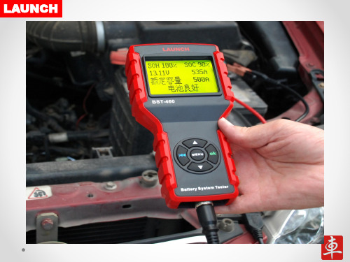
产品说明书:BST系列蓄电池检测仪培训PPT中文
LAUNCH
6、蓄电池检测仪主要客户
4)汽保设备经销商;
★客户购买其他产品时,作为赠品送客户;
5)教育机构、职业学校等;
★作为教学、演示、判断汽车故障位置的工具,便于教学和 演示;
市场排名
N/A
1
2
3
配置
标配0-900A电流钳, 无电流钳,
内置打印机
内置打印机
0-700A电流钳选配,电流钳选配,
内置打印机
打印机外置选配
测试功能
测电池、起动和充电 系统;
测电池、起动和充 电系统;不能测起 动和充电电流值;
测电池、起动和充电 测电池、起动和充
系统;
电系统;
多语言菜 单
中、英、日、俄、西、 法、德、等13种以上 英、法、葡 的语言;
BST-760 √ √ √ √ √ √ √ √ √ √ √ √ √ √
√
LAUNCH
3、元征蓄电池检测仪的优点
3.5 其他优点
可以直接探测坏格电池,放电电池,无需充满电再测试; --大大工作提高效率;
具有温度自动补偿功能;带有纹波电压测试功能; --测试准确、直观;
符合人体学的外观设计,人性化的高级语言提示界面; --便于操作;
中高端 562.99US
经销商 利润
大于50%
20-30%
20-30%
20-30%
售后 维修方便,费用低 维修零件费用贵 维修零件费用贵 维修零件费用贵
品牌知 名度
高
高
高
低
LAUNCH
Giga-tronics 8650A系列通用电源表说明书
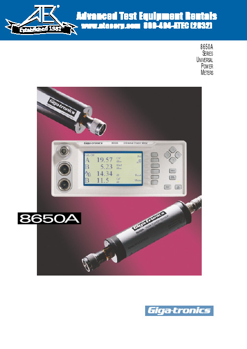
19818650AS ERIESU NIVERSALP OWERM ETERSThe Giga-tronics 8650A Series combines the speed,range and capabilities needed to test today’s sophisticated communications systems.sors,or from forgetting toThe Secret is the SensorsPULSE POWER MEASUREMENTS Attach a Giga-tronics 80350A Series Peak Power Sensor to an 8650A meter and directly measure the instantaneous peak power level of a pulse modulated e the ‘sample delay’ function to set the desired measurement point on the wave-form.And an external scope can be used to view the profile and see the exact measurement point on the pulse.Giga-tronics power meter architecture provides for a broad choice of functional sensors.Just by changing a sensor,you can measure CW power,pulse power,and the peak and aver-age power of TDMA,GSM and CDMA signals faster,more accurately,and over a wider range.THEFASTESTCW MEASUREMENTSGiga-tronics 80300A Series CW Power Sensors let you measure CW power from 10 MHz to 40 GHz at more than 1,750readings per second over GPIB.Measure up to 90 dB with a single sensor,and select from a variety of high power sensors,up to 50 W .MODULA TEDPOWER MEASUREMENTSThe Giga-tronics 80400A Series Modulated Power Sensors let you measure the average power of ampli-tude modulated,burst modulated and other complex modulated signals — suchas TDMA signals — at bandwidths up to 40 kHz.The Giga-tronics 80600A Series Modulated Power Sensors provide bandwidth up to 1.5 MHz to measure the peak and average power of CDMA signals.And the Giga-tronics 80701A Modulated Power Sensor operating with the 8650A power meter,provides system bandwidth up to 10 MHz to measure the peak and average power of wide band,third-genera-tion CDMA signals over an 80 dB range.Displays of IntelligenceSEE FOR YOURSELFThe 8650A incorporates a 3.72” wide by 2.15” high Liquid Crystal Display (LCD)with 240 x 120 dot resolu-tion,0.38 mm dot pitch,and Cold Cathode Fluorescent Lamp (CCFL) back light for maximum detail and opti-mum viewing.The large display lets you see more information.And the display works in tandem with the meter controls to let you view menu selections and see your input data as you enter it.Y ou can view calibration information,select a standard mode,setup and recall pre-configured,custom modes,and set measurement points and durations.Each sensor uses an EEPROM to store values of cal factor.Enteringthe measurement frequency automatically calls up the correct cal factor.If the measurement frequency is between cal factor points,the meter automatically enters an interpolated value.An extensive list of help panels provide assistance in setting up special features and guidance in making the measurement.A volts per frequency input isavailable to set the cal factor when connected to an RF source.As the source frequency is modified the V/F output will automatically set the power meter to the correct cal factor,thereby eliminating the need for manual input.Peak (Pulse) power sensors can be set to the desired measurement point of a pulse signal.The trigger point can be set using an internalpower level or a TTL signal.Recall setup can be used to pre-configure measurement modes for later use.Full descriptive details help to clearly identify the settings before recall.The graphic display provides visual feedback as you set the measurement start time and duration of the time gate to measure the average power during a specific time period.View the mean power and standard deviation of the modulated signal over a time period of interest.Standard deviation offers an alter-native descriptive analysis of the power variation when compared to the traditional crest factor.ST A TISTICAL ANAL YSISExcessive cost can prove as detrimental to the success of communications equipment as inadequate performance.The 8650A provides a range of statistical power measurement analysis fea-tures that help you optimize your designs to prevent inad-equate performance due to under design or excessive cost due to over design.These features include crest factor,standard devi-ation,strip chart,CDF/CCDF ,and histogram,and they let you view and thoroughly analyze the power signal over a selected period of time.Combined,they make the 8650A the most advanced power meter available for communications systemsdesign.The histogram function allows youto view a power range distribution over a period of time.The x axis displays the minimum to maximum power levels measured during the interval time period,and the y axis displays the percent of time each power level is measured.A zoom feature lets you view smaller seg-ments of the power range to bet-ter analyze the percentage of time a specific power level has occurred.The strip chart function allows you to view the vary-ing power levels of a signal over a period of time.The x axis displays time from the start of the meas-urement to a selectable period of 1 to 200 minutes,and the y axis displays the minimum to maximum power levels measured during the selected period.Moving a cursor along the x axis displays time and the corresponding power level.The Cumulative Distribution Function (CDF) shows the percentage of time a signal is below a selected power level.Thex axis displays the amount of power at the selected level,meas-ured in dBm,and the y axis dis-plays the percentage of time the power is at or below the power specified by the x axis.The Complementary Cumulative Distribution Function (CCDF) reori-ents the CDF curve in accordance with the equation CCDF = 1-CDF for more accustomed viewing of a descending slope.Moving a cursor along the slope of the curve dis-plays the power level in dBm and the corresponding percentage of time the signal is above that level.The K connector is electrically and mechanically compatible with the APC-3.5 and SMA connec-tors.Note:Use a Type N(m) to SMA(f) adapter (part no.29835) for calibration of power sensors with Type K(m) connectors.Power coefficient equals <0.01 dB/Watt.Power coefficient equals <0.015 dB/Watt.For frequencies above 8 GHz,add power linearity to system linearity.Power coefficient equals <0.01 dB/Watt (Average).Power coefficient equals <0.015 dB/Watt (Average).Peak operating range above CW maximum range is limited to <10% duty cycle.Square root of the sum of the individual uncertainties squared (RSS).Cal Factor numbers allow for 3% repeatability when reconnecting an attenuator to a sensor and 3% for attenuator measurement uncertainty and mismatch of sensor/pad combination.Depending on sensor used.MAP (Modulated Average Power),PAP (Pulse Average Power),BAP (Burst Average Power).Specified performance applies with maximum averaging and 24 hour warm-up at constant temperature.Operates in Normal Mode only.Display contrast reduces above 50°C.Does not apply to 80701A Sensor below 500 MHz.Specifications subject to change without notice.Specifications describe the instrument’s warranted performance,and apply when using the 80300A,80400A,80600A,and 80700A Series Sensors.METERFrequency Range:10 MHz to 40 GHz 10Power Range:-70 dBm to +47 dBm (100 pW to 50 Watt) 10Single Sensor Dynamic Range:10CW Power Sensors:90 dB Peak (Pulse) Power Sensors:40 dB,Peak50 dB,CWModulation Power Sensors:87 dB,CW80 dB,MAP/PAP 1160 dB,BAP 11Display Resolution:User selectable from 1 dB to 0.001 dB in Log mode,and from 1 to 4digits of display resolution in Linear mode.Meter FunctionsMeasurement Modes (Sensors):CW (80300A,80350A,80400A,80600A,and 80700A Series)Peak (80350A Series)MAP/PAP/BAP 11(80400A,80600A,and 80700A Series)Averaging:User selectable,auto-averaging or manual from 1-512 readings.Timed averaging from 20 ms to 20 seconds.dB Rel and Offset:Power display can be offset by -99.999 to +99.999 dB to account for external loss/gain.Configuration Storage Registers:Allows up to 20 front panel setups.Power Measurements and Display Configurations:Any two of the following channel configurations,simultaneously:A,B,A/B,B/A,A-B,B-A,DLYA,DLYB Number of Display Lines:4Sampling:CW and Modulation Mode: 2.5 to 5 MHz asynchronous Analog Bandwidth:CW Mode:≥3 kHzModulation Mode:>10 MHz Time Gating:Trigger Delay:0 to 327 ms Gate Time:10 µs to 327 ms Holdoff Time:0 to 327 ms ACCURACY50 MHz Calibrator:(Standard)Calibrator:+20 dBm to -30 dBmpower sweep calibration signal to dynamically linearize the power sensors.Connector:Type N,50 ΩFrequency:50 MHz,nominal0.0 dBm Accuracy:±1.2% worst case for one year,over temperature range of 5º to 35ºC.VSWR:<1.05 (Return Loss >33 dB) @0 dBm.1 GHz Calibrator:(Option 12)Required for 80700A Series Sensors.Calibrator:+20 dBm to -30 dBmpower sweep calibration signal to dynamically linearize power sensors.Connector:Type N,50 ΩFrequency:(Switchable):1 GHz,nominal;50 MHz,nominal0.0 dBm Accuracy:±1.2% worst case for one year,over temperature range of 5º to 35ºC.VSWR:<1.07 (Return Loss >30 dB) @0 dBm.800 MHz - 1 GHz Synthesizer Specifications:(Option 12)Power Range:+15 dBm to -30 dBm,settable in 1 dB steps.Frequency:800 MHz to 1 GHz,settable in 1 MHz steps.Power Stability:<0.1 dB/Hour Frequency Accuracy:±0.05%Instrumentation Linearity:±0.02 dB over any 20 dB range from -70 to +16 dBm.15±0.02 dB + (±0.05 dB/dB) from +16 to +20 dBm.±0.04 dB from -70 to +16 dBm.Graph shows linearity plus worst case zero set,and noise versus input powerTemperature Coefficient ofLinearity:<0.3%/ºC temperature change following Power Sweep calibration.24 hour warm-up required.Zeroing Accuracy:(CW)Zero Set:12<±50 pW,<±100 pW with80400A and 80600A Series Modulation Power Sensors.<±200 pW with 80700A Series Sensors.Zero Drift:12<±100 pW during 1 hour,<±200 pW with 80400A and 80600A Series Sensors,<±400 pW with 80700A Series Sensors.Noise:<±50 pW,<±100 pW with 80400A and 80600A Series Modulation Power Sensors.<±200 pW with 80700A Series Sensors.Measurable over any 1 minute interval after zeroing,3 standard deviations.REMOTE INPUTS/OUTPUTSV Prop F Input (BNC):Sets calibration factors using source VpropF output.13Analog Output (2) (BNC):Provides an output voltage of 0 to 10V for Channels 1 and 2 ineither Lin or Log units.13Does not operate in Swift or Buffered modes .Trigger Input (BNC):TTL trigger input signal for Swift and Fast Buffered modes.GPIB Interface:IEEE-488 and IEC-625 remote programmingRS232 Interface:Programmable serial interface,DB-9 connector GENERAL SPECIFICATIONS Temperature Range:Operating:0º to 55ºC (+32º to +131ºF)14Storage:-40ºC to 70ºC (-40º to +158ºF)Power Requirements:100/120/220/240V ±10%,48 to 440 Hz,25VA typical Physical Characteristics:Dimensions:215 mm (8.4 in) wide,89 mm (3.5 in) high,368 mm (14.5 in) deep Weight:4.55 kg (10lbs)ORDERING INFORMATION POWER METERS 8651A Single Input Universal Power Meter(includes 1 sensor cable)8652A Dual Input Universal Power Meter(includes 2 sensor cables)ACCESSORIESOne manual,one power cord.POWER METER OPTIONS 01Rack mount kit038651A Rear Panel Sensor and Calibrator Connections 048652A Rear Panel Sensor and Calibrator Connections 05Soft Carry Case07Side Mounted Carrying Handle08Transit Case,(Includes Soft Carry Case)09Dual Rack Mount Kit (with assembly instructions)10Dual Rack Mount Kit (factory assembled)12 1 GHz,50 MHz Switchable Calibrator 138651A Rear Panel Input Connector 148652A Rear Panel Input Connectors80301A 80310A 80320A 80321A 80322A 80325A 80330A80401A, 80601A (CW)80701A (CW)-70-64-60-50-40-40-30-67-64-60-54-50-40-30-30-20-57-54-50-44-40-30-20-20-10-47-44-40-34-30-20-10-100-37-34-30-24-20-100010-27-25-20-14-100101020-17-16-10-40102020-7-7061020303033101620304040131320253040445020203210-1-2-3S E N S O R ST Y P I C A L E R R O R (d B )Input, (dBm)Giga-tronics Incorporated 4650 Norris Canyon Road San Ramon,California 94583T elephone:800 726 4442 or925 328 4650T elefax:925 328 4700Web Site:© 1999 Giga-tronics IncorporatedGT-167-B。
无线蓄电池测试系统V3.0-杭州高特电子设备有限公司

无线蓄电池测试系统用户手册V3.0杭州高特电子设备有限公司一、 概述随着社会的进步和信息化、自动化程度的不断提高,人们对电力、通信、金融、交通等行业的依赖程度进一步加深,同时对供电系统的可靠性提出了更高的要求。
无论在电力变电站、电信机房、移动基站还是在UPS系统中,蓄电池作为备用电源在系统中起着极其重要的作用。
平时蓄电池处于浮充电备用状态,由交流市电经整流设备变换成直流向负荷供电,而在交流电失电或其它事故状态下,蓄电池是负荷的唯一能源供给者,一旦出现问题,供电系统将面临瘫痪,造成设备停运及其它重大运行事故。
阀控式铅酸蓄电池俗称“免维护”蓄电池,它的应用大大减少了开口式铅酸蓄电池繁琐复杂的维护工作,然而,其“免维护”的优点,正是运行管理的缺点和难点。
除了正常的使用寿命周期外,由于电池本身的质量如材料、结构、工艺的缺陷及使用不当等问题导致一些蓄电池早期失效的现象时有发生。
所谓“免维护”仅仅指无需加水、加酸、换液等维护,而日常维护仍是必不可少的,开口式铅酸蓄电池运行检测维护方法已不再适用于阀控式铅酸蓄电池,这就对蓄电池测试设备提出了新的要求。
因此在提高蓄电池性能、减少维护工作量的同时,如何快捷有效地检测出早期失效电池、预测蓄电池性能变化趋势已成为蓄电池运行管理的重中之重,这对无人值守变电站、通信机房、移动基站及UPS系统中尤为重要。
为了检验蓄电池组的可备用时间及实际容量,保证系统的正常运行,一般需要对蓄电池组每年进行一次核对性放电测试。
蓄电池组的性能取决于整组电池中性能最差的一节,因此需要在放电过程中对每一节电池的电压进行监测,以便在单体电池电压跌至放电下限时停止放电,避免蓄电池损坏,并对每一节电池的性能进行分析。
目前单体电池电压的监测主要有两种方式:手动测量和有线自动测量。
手动测量由于时间上无法做到连续和同步,人为误差较多,精度较差,因此无法对蓄电池的性能做出较为精确、客观的判断,且工作量大。
有线自动测量虽然提高了数据采集的速度和精度,减少了工作量,但连线较多,操作复杂,有一定的安全隐患,且无法排除一线制采集时电池间连接导线产生的“过桥电压”对测量数据的影响。
REGATRON G5.BT系列电池测试仪说明书

G5.BT Battery Tester SeriesThe G5.BT series is bidirectional regenerative. It was developed specifically for testing energy storage devices and is suitable for use in laboratories and on test benches. The modular and finely graded G5.BT series is characterized by highly dynamic response times and a wide cur-rent-voltage range with an auto-ranging factor 3. The G5.BT series has an outstanding current accuracy of <0.02% FS, an additional high-resolution current measurement range, and a fast current rise time in the 100 μs range. Ripple modulation, an integrated safety relay for PL c according to EN ISO 13849 and a powerful CAN multi-protocol interface (1 kHz, 16 bit) as well as functions to avoid reverse-polarity problems, current surges, and unwanted deep discharg-es make the G5.BT series the ideal, versatile battery module and battery pack tester.Device TypesVoltage V Power kW Current A Height U Order Code 0...500 18 -108...108 4 G5.BT.18.500.108 0...500 27 -162...162 7 G5.BT.27.500.162 0...500 36 -216 (216)7 G5.BT.36.500.216 0…500 54 -324…324 10 G5.BT.54.500.324 0…1000 18 -54…54 4 G5.BT.18.1000.54 0…1000 36 -108…108 7 G5.BT.36.1000.108 0…1000 54 -162…162 10 G5.BT.54.1000.162 0…1500 27 -54…54 7 G5.BT.27.1500.540…1500 54 -108…108 10 G5.BT.54.1500.108Modular and Easy Scalable SystemsThe output of an individual power supply is in the range from 0...18 kW to 0...2000+ kW, up to 3000 VDC. The advantageous modularity of REGATRON power supply solutions allows the system to be easily adapted to ever changing test requirements. Not only is it possible to reconfigure between parallel, series, and mixed operation, but also to expand the systemwith additional power supply units or to split it intosmaller units.Therefore, the purchase of a REGATRON power supply is a solid investment for the future.Figure 1: Modular concept for easy power and voltage increase by parallel, series, and mixed operation. The parallel configuration allows even an operation of different power levels, e.g., 18, 36, and 54 kW modules, in one system.Whether for single devices or powerful multi-device master-slave systems, REGATRON also offers turn-key cabinet solutions or project specific system integration according to customer specifications. Battery Module/Pack-Testing FeaturesThe G5.BT series has an exceptional electrical performance that offers several advantages for battery testing applications:▪Accuracy of <0.02% FS▪Additional high-resolution currentmeasurement range from -10 to 10% FS ▪Current rise time in the 50…200 µs range▪Parameterizable to avoid overshoot▪Current ripple modulation up to 10 kHzIn addition, the G5.BT provides important features for user safety, power supply, and battery protection. It avoids:▪Reverse-polarity problems▪Arcing and high inrush current whenconnecting the battery to the DC terminalseven at unmatched voltage levels▪Deep battery discharge at voltage off state (DC port impedance >10 MΩ)Features such as adjustable controller settings and the integrated powerful 8-channel digital scope assist the user to quickly and easily achieve optimal system behavior for a special application requirement. The G5.BT series also offers the possibility to store, edit and recall any device configuration on board the power supply.DynamicsMaximum speed or minimum overshoot? Figure 2 shows that the dynamic parameters of the G5.BT series can be easily adapted to a specific task.Figure 2: Parameterization example: set-value step currents. -97…97 A@333VDC in <50 µs with overshoot (top), in <200 µs w/o overshoot (bottom). General Dynamic DataInterfacesCAN InterfaceThe CAN multi-protocol (CANmp) interface has a 1 kHz data rate, a 16-bit resolution and is adaptable to any proprietary CAN bus. In addition, it supports dbc file handling.Integrated Safety RelayIntegrated safety relay (ISR) for increased emergency stop reliability supporting performance level PL c / PL e according to EN ISO 13849.Control ModesCV constant voltageCC constant currentCP constant powerCR constant resistanceRi internal resistance simulationSystem ControlG5.Control operating and maintenance software API .NET programming, e.g., by LabView,Python, Matlab, or REST interface I/O port Analog interface for set and actualvalues, operating statesGrid ConnectionThe wide-band AC input accepts all common AC grid systems and has an active power factor correction.AC Grid 380…480 VAC ±10% at 50/60 HzPF 0.99Efficiency 95…96%OptionsSoftware and ControlBatControlThe battery tester is controlled by interfaces such as CANmp for the integration into automated test benches or by the optional application software BatControl for R+D applications in the laboratory. BatControl allows selecting and running so-called BatScripts. These scripts automate the manually given commands to the G5 Battery Tester and allow the running of these commands according to defined schedules.▪Define charge and discharge algorithms▪Run drive cycles (according to own or already defined standards)▪Repeat previously recorded discharge/charge dataTime-Based Function GeneratorThe TFE time-based function generator allows programming either through G5.Control operating software, HMI touch display, or CANmp interface.▪Time-dependent functions U = f(t), I = f(t), P = f(t): sine, triangle, or square as well as user-defined data points. Import and exportthrough csv files supported▪Sweep function for current ripple modulation 0…10 kHzHMIThe HMI built into the front panel allows compre-hensive and convenient operation of the power supply via touch display.Figure 3: Intuitive control by HMI touch display. Everything you need at a glance. User Safety▪Discharge of AC filter (XCD), recommended for mobile use of the device. XCD ensures adischarge time of the AC filter <1 s requiredby EN 50178▪AC terminal protection cover (PAC.AC),recommended for use as tabletop unitRack-Integrated System Solutions▪Mobile rack solutions up to IP54▪Insulation monitoring: remote activation of the insulation measurement, actual insulation valueand warning/error status are provided byCANmp interface or by optional HMI▪Easy reconfiguration between parallel, series, and mixed operationFigure 4: REGATRON’s rack-integrated turn-key system solutions, e.g., 72 kW (left) and 162 kW (right) power levels. Various types of AC/DC connectors and cables allow for comfortable handling. Third-party product integration and numerous safety options are additional features.Environmental ConditionsFront-panel-mounted air filter (AirFilter), recom-mended for use in dusty environments.NEWDC Generation 5REGATRON DC & AC Power Supplies: Modular ∙ Precisely Engineered ∙ Technologically AdvancedImportant Features of the G5.BT SeriesTechnology▪ Technologically advanced, fast switching,compact 19-inch power supplies▪ High control dynamics in the 100...200 µsrange – even at higher power levels▪ Exceptional accuracy of <0.02% FS, additionalhigh-resolution measurement range ▪ Wide current-voltage range with an auto-ranging factor 3▪ CV, CC, CP, CR, and Ri-Sim control modes ▪ Regenerative and highly efficient, resulting insignificant reduction of energy consumption and heat dissipationSystem Capability▪ Modular and easy scalable systems▪ Parallel, series, and mixed operation with adigital high-speed bus▪ Simple master-slave configuration with theoperating software ▪ Easy rack mounting▪ Optional safety features such as 2-channelsafety interface and insulation monitoring ▪ Turn-key cabinet solutions or project-specificsystem integration according to customer specificationSystem Control and Options▪ Operating software, extended analysis, andparameterization options, calibration ▪ Application software with visualization,programming, and data logger▪ Powerful application programming interfaces(APIs)******************All product specifications and information herein are provisional and subject to change without notice. Filename: PD_G5.BT_EN_201007.docxnd ***************************************.com。
电池内阻测试仪说明书-7页word资料

CKNZ8蓄电池内阻测试仪使用说明书河北创科电子科技有限公司目录电池内阻测试仪使用说明书 (2)概述 (2)技术参数 (2)操作说明 (2)测试提示 (3)测试容量 (3)单节测量 (4)成组测量 (4)示波器 (4)数据管理 (5)数据查询 (5)转存U盘 (5)数据删除 (5)系统管理 (5)时钟设置 (6)系统参数 (6)计量校正 (6)更新程序 (6)附录:电池状态判断方法及电池内阻列表 (6)CKNZ8电池内阻测试仪使用说明书概述测试仪结构图关于测试仪该测试仪是一种手持式测试仪,可执行的功能有:单节测量、成组测量、数据管理、系统管理。
便携式用户界面友好充电电池,待机时间大约为2-4小时大屏幕点阵LCD显示术语使用以下定义或缩写:Temp 温度(Temperature)技术参数测量范围内阻:0.0mΩ--100mΩ电压:0.000v--16v最小测量分辨率内阻:0.01 mΩ电压:1mV测量精度内阻:±2.0%rdg ±6dgt电压:±0.2%rdg ±6dgt供电电源锂电池供电直流16.8V1A适配器功率消耗连续工作不小于4小时(16.8V 1300mAH)存储容量64K I2C显示器128x 64 点阵图形LCD尺寸260 x 142 x 70 mm重量 1.3 Kg工作温度 -10℃--50℃ 湿度 小于85%RH操作说明本部分主要讲解电池内阻测试仪的操作。
测试提示● 使用测试仪进行测试时,应观察所有设备制造商的注意事项和警告。
● 测试前应仔细检查所有测试引线的连接。
● 确认加载/感应夹均连接在电池的接线柱上。
● 确认正极和负极夹均正确连接在电池的接线柱上。
● 如果极性接反,测试仪将显示:“极性接反,检查连接”。
● 电池夹必须与电池连接牢固。
否则将出现错误诊断。
对于接线柱在侧面的电池,将测试夹夹在圆形电缆的接线端,而不是方形电缆的接线端。
测试仪参数说明书

Parameters Measured: Measurement Circuit Mode:Displays:Measurement Terminals: Ranging Mode:Test Frequency:Freq Accuracy: Measurement Rate:Test Signal Level: Response Time:Temperature Coefficient:Operation Temperature: Storage Temperature:10M 9.999M 1M 999.9k 100k 99.99k 10k 9.999k 1k 999.9100k 99.99109.999ΩΩΩΩΩΩΩΩΩΩΩΩΩNOTES:1. This specification is based on the measurement performed at the test socket2. DUT & Test lead to be properly shielded to GND (DC "-") if necessary.3. This specification is based on internal power (battery) operation.Resistance ΩPower Requirements1) Battery: DC 9V Battery2) Ext. DC Adaptor: DC 12Vmin-15Vmax (LOAD 50mA min)Low Battery Indication : Approx. 6.8VPower Consumption: Approx. 40 mA; 0.3mA Auto Power-offProtective Fuse: 0.1A fast-blow 250V AC (Pleaserefer to Safety Information)Auto Power-Off Time: Approx. 5 mins.Dimensions: 37 mm(H) x 90 mm(W) x 192(L)Weight: 390gStandard Accessories: Test alligator clips (pair), battery (DC 9V), spare fuse (0.1A/250V AC fast-blow)and operator manualElectrical Specifications All accuracies are @ 23°C; <75% R.H.±(0.5%+5 counts)±(0.5%+3 counts)±(0.5%+3 counts)±(0.5%+3 counts)±(0.8%+5 counts)±(1.2%+8 counts)±(2%+8 counts) *(note 3)Test Freq. 1KHz ±(2%+8 counts) *(note 3)±(0.5%+5 counts)±(0.5%+3 counts)±(0.5%+3 counts)±(0.5%+3 counts)±(0.8%+5 counts)±(1.2%+8 counts)Specified Note after open cal.after open cal.after short cal.after short cal.AccuracyTest Freq. 120HzDF 10mF9.99mF (note 4)A (5% + 5 counts) (DF<0.1)A (10% + 100/Cx + 5 Counts) (DF<0.1)1000µF999.9µF A (1% + 5 counts) (DF<0.1)A (2% + 100/Cx + 5 Counts) (DF<0.1)100µF99.99µF 10µF9.999µF 1000nF999.9nF 100nF99.99nF A (0.7% + 5 counts) (DF<0.5)A (0.7% + 100/Cx + 5 Counts) (DF<0.5)10nF 9.999nF A (1% + 5 counts) (DF<0.1)A (2% + 100/Cx + 5 Counts) (DF<0.1)DF 1000µF0.999mF A (5% + 5 counts) (DF<0.1)A (10% + 100/Cx + 5 Counts) (DF<0.1)100µF99.99µF A (1% + 5 counts) (DF<0.1)A (2% + 100/Cx + 5 Counts) (DF<0.1)10µF9.999µF 1000nF999.9nF 100nF99.99nF 10nF9.999nF 1000pF 999.9pF A (1% + 5 counts) (DF<0.1)A (2% + 100/Cx + 5 Counts) (DF<0.1)Specified Note after short cal.A (0.7% + 3 counts) (DF<0.5)A (0.7% + 100/Cx + 5 Counts) (DF<0.5)after open cal.Test Frequency: 120HzTest Frequency: 1kHzRangeMax. Display Accuracy A (0.7% + 3 counts) (DF<0.5)A (0.7% + 100/Cx + 5 Counts) (DF<0.5)after short cal.after open cal.RangeMax. Display Accuracy Specified Note NOTES:1. Q value is the reciprocal of DF2. This specifiction is based on the measurement performed at the test socket3. Dut & test lead to be properly shielded to GND (DC "-") if necessary4. This reading can be extended to 1999 MAX display with accuracy not specified5. Cx = Counts of displayed C value e.g. C=88.88µF then Cx=8888Capacitance(note 4)(DF<0.5)(0.7% + 5 counts) Cx (Note 5)Cx (Note 5)DF (DF<0.5)10000H9999H Note 4Note 4- - - - 1000H999.9H A [1% + (Lx/10000)% +5 counts]A (2% + 100/Lx + 5 Counts)after open cal.100H99.99H - - - -10H9.999H - - - -1H999.9mH - - - - 100mH99.99mH A [1% + (Lx/10000)% +5 counts]A (3% + 100/Lx + 5 Counts)10mH 9.999mH A [2% + (Lx/10000)% +5 counts]A (10% + 100/Lx + 5 Counts)DF (DF<0.5)1000H999.9H Note 4Note 4- - - -100H99.99H A [1% + (Lx/10000)% +5 counts]after open cal.10H9.999H - - - -1H999.9mH - - - -100mH99.99mH - - - - 10mH9.999mH A [1.2% + (Lx/10000)% +5 counts]A (5% + 100/Lx + 5 Counts)1mH 999.9µH A [2% + (Lx/10000)% +5 counts]A (10% + 100/Lx + 5 Counts)A [0.7% + (Lx/10000)% +5 counts]A (1.2% + 100/Lx + 5 Counts)after short cal.RangeMax. Display Accuracy Specified Note A [0.7% + (Lx/10000)% +5 counts]A (1.2% + 100/Lx + 5 Counts)after short cal.Test Frequency: 1KHz Test Frequency: 120Hz RangeMax. Display Accuracy Specified Note NOTES:1. Q value is the reciprocal of DF2. This specifiction is based on the measurement performed at the test socket3. DUT & test lead to be properly shielded to GND (DC "-") if necessary4. Not specified5. Lx = Counts of displayed L value e.g. L=88.88µF then Lx=8888InductanceLx (DF<0.5) (Note 5)Lx (DF<0.5) (Note 5)。
BT3562 3561 电池测试仪 技术参数说明书

电子测量仪表L2100 针型测试线9454 调零板9637 RS-232C连接线(9pin-9pin)9638 RS-232C连接线(9pin-25pin)9151-02 GP-IB连接线(2m)9770 针型测试线9771 针型测试线9287-10 夹型测试线9453 4端子测试线9467 大口径夹型测试线L2100 针型测试线9454 调零板9637 RS-232C连接线(9pin-9pin)9638 RS-232C连接线(9pin-25pin)9151-02 GP-IB连接线(2m)9770 针型测试线9771 针型测试线9287-10 夹型测试线9453 4端子测试线9467 大口径夹型测试线标配仅-01型号标配3561-01标配35613561-01电池测试仪BATTERY HiTESTER用于小型充电电池的出货/验收的高速检查从大型元件检查到高压电池组产线皆可高速测量● 能够测量高达300V的高压电池组(BT3563)●高压电池组/电池模块的产线检查●大型(低电阻)元器件检查● 多种外部接口对应不同产线需求※合格判断的标准值需要根据电池的种类由客户输入。
● 适用于手机、笔记本电脑等小型充电电池生产线● 除了内阻和电压检查,还增加了针对工程/品质管理的运算功能● 丰富的接口可用于高速系统测试生产线中※合格判断的标准值需要根据电池种类由使用者输入。
BT3562BT3563电池测试仪BATTERY HiTESTER技术参数BT3562(-01)BT3563(-01)最大输入电压额定输入电压:DC±60V 对地最大额定电压:DC 70V 额定输入电压:DC±300V 对地最大额定电压:DC 300V 阻抗量程3mΩ(最大显示3.1000mΩ,分辨率0.1μΩ)~3000Ω量程(最大显示3100.0Ω,分辨率100mΩ),7档切换测量精度:±0.5%rdg.±5dgt.(30mΩ~3000Ω量程,EX.FAST 时需加算±3dgt.,FAST/MEDIUM时需加算±2dgt.)±0.5%rdg.±10dgt.(3mΩ量程,EX.FAST时需加算±30dgt.,FAST时需加算±10dgt.,MEDIUM时需加算±5dgt.)测量源频率:1kHz±0.2Hz。
蓄电池内阻测试标准

蓄电池内阻蓄电池的内阻是指蓄电池在工作时,电流流过蓄电池内部所受到的阻力,一般分为交流内阻和直流内阻,由于充电电池内阻很小,测直流内阻时由于电极容量极化,产生极化内阻,故无法测出其真实值,而测其交流内阻可免除极化内阻的影响,得出真实的内值。
YXD-3006蓄电池的容量主要是和极板上活性物质的利用率有关。
而蓄电池极板上的活性物质是:二氧化铅、铅。
在蓄电池内部的化学反应过程中,其实质就是极板上的活性物质和稀硫酸电解液发生的电化学反应,产生电流。
在这个电化学反应过程中,经常伴随着一种学名叫“硫酸盐化的”负反应,也就是铅和硫酸生成了一种硫酸铅,这种硫酸铅是一种绝缘体,它的形成必将对电池的充放电产生极不好的影响,因为在负极板上形成的硫酸盐越多,电池的内阻越大,电池的可充放电性能越差,负极板上吸收不了正极产生的气体,久而久之电池失效。
而且影响铅酸蓄电池容量的因素有很多:放电率、温度、终止电压、极板几何尺寸、电解液浓度等。
电池的内阻:欧姆电阻和极化内阻欧姆电阻:电极材料、电解液、隔膜的电阻。
YXD-3006蓄电池内阻测试仪极化内阻:正负极化学反应时引起的内阻两者并不是直接影响的,而是通过影响其他方面来影响对方。
也就是说,两者并没有直接的关系,而是通过影响对方的制约因素来影响对方。
例如:温度的变化可以影响到电池的电解液和电阻变化。
1)电解液温度升高,扩散速度增加,电阻降低,电动势增加,因此电池容量及活性物质的利用率随温度增加而增加 2)电解液温度降低大,黏度增大,离子运动受阻,扩散能力降低,电阻增大,电化学反应阻力增加,导致蓄电池容量下降。
蓄电池检测内阻已经成为比较流行判断电池好坏的方式.影响蓄电池内阻的因素1.蓄电池的内阻由欧姆极化(导体电阻)和电化学极化及浓差极化电阻三个部份组成。
在充放电过程中电阻是变化的,充电过程内阻由大变小,反之内阻增加。
2.温度对蓄电池内阻也颇有影响,低温状态如0℃以下,温度每下降10℃,内阻约增大15%,其中因硫酸溶液粘度变大,而增加了比电阻是重要的原因之一。
BTS20单体电芯测试设备使用手册说明书
股票代码:870725适用于BTS20单体电芯测试设备衷心感谢您购买德普测试设备!为确保您安全使用本设备及令本设备更加持久请在使用本设备前,认真阅读本使用手册,并请正确操作本使用手册请保留备用BTS20单体电芯测试设备BTS20 SINGLE CELL TEST EQUIPMENTmade inEOL模组测试工作站模组充电测试平台模组测试工作站成品自动测试生产线PACK自动产线▶▶▶▶▶目 录BTS20单体电芯测试设备使用手册安全注意事项 (01)一. 产品概述 (02)1.1产品简介 (02)1.2产品结构及拓扑图 (02)二. 安装说明及注意事项 (03)三. 软件说明 (04)3.1软件简介及拓扑图 (04)3.2启动软件 (04)3.2.1启动上位机服务器 (04)3.2.2打开上位机监控系统 (05)3.3登陆和注销 (06)3.3.1业务描述 (06)3.3.2操作说明 (06)3.4 系统 (07)3.4.1业务描述 (07)3.4.2操作说明 (07)3.5工艺 (15)3.5.1业务描述 (15)3.5.2操作说明 (16)3.6运行设备 (21)3.6.1业务描述 (21)3.6.2操作说明 (21)3.7参数 (25)3.7.1业务描述 (25)3.7.2操作说明 (25)3.8数据 (28)3.8.1业务描述 (28)3.8.2操作说明 (28)3.9电池配号 (35)3.9.1业务描述 (35)3.9.2操作说明 (35)3.10用户 (36)3.10.1业务描述 (36)3.10.2操作说明 (36)四.设备故障及处理 (37)安全注意事项安全须知危险单体5v 低压大电流、30V/60v/100v 高压大电流两种系列测试设备,是一种带能量管理及分配功能的测试系统,通过先进的矢量控制算法配合锂电池行业成熟的测试工艺,达到对电池组的性能进行综合测试的目的,系统在整个测试过程中具有高效、节能、对电网无污染的特点,其功能及技术指标达到国际同类先进水平,测试过程基本不消耗电能。
- 1、下载文档前请自行甄别文档内容的完整性,平台不提供额外的编辑、内容补充、找答案等附加服务。
- 2、"仅部分预览"的文档,不可在线预览部分如存在完整性等问题,可反馈申请退款(可完整预览的文档不适用该条件!)。
- 3、如文档侵犯您的权益,请联系客服反馈,我们会尽快为您处理(人工客服工作时间:9:00-18:30)。
产品参数
测量范围:内阻:0.0mΩ--100mΩ电压:0.000v--16v
2、测量精度:内阻:±2.0%rdg ±6dgt
3、供电电源:锂电池供电直流12.76A适配器
4、电压:±0.2%rdg ±6dgt
5、显示器:TFT(320×240)真彩液晶显示屏
6、存储容量:2GB(SDDisk) + 128MB(NandFlash),FAT32格式文件系统。
7、最小测量分辨率内阻:0.01 mΩ,电压:1mV
8、功率消耗:连续工作不小于4小时(12.0V 3000mAH)
9、海拔高度:≤2000m 环境温度:-40℃ ~ 85℃
10、工作温度:-5℃ ~ 45℃
11、对湿度:5%~ 95%
12、尺寸:220 x 100 x 80 mm
13、重量:1.3 Kg
产品简介
NRBT-8650 智能蓄电池内阻测试仪是用于测量电池内部阻抗和电池酸化薄膜破损程度的仪器。
内阻的测量方法主要有瞬间直流放电法和交流信号注入法,我们选用的直流
放电法来测量蓄电池的动态内阻,能够很好地反映电池欧姆电阻、化学电阻。
利用内
阻阻值的大小来判断电池的劣化状态,预估电池容量,(一般来说)其阻值越小电池
的性能越好。
因此,采用内阻进行测量电池的方法是速度快且可靠性较高的一种判别
电池优劣好方法。
产品别称
蓄电池内阻测试仪、蓄电池内阻检测仪、蓄电池内阻仪、智能蓄电池内阻测试仪、智
能蓄电池内阻检测仪、智能蓄电池内阻仪、便携式蓄电池内阻检测仪、便携式蓄电池
内阻测试仪、手持式蓄电池内阻测试仪、手持式蓄电池内阻检测仪、蓄电池内阻监测仪、蓄电池内阻智能测试仪、蓄电池内阻容量测试仪、蓄电池内阻监测仪、蓄电池内阻巡检仪、蓄电池在线内阻检测仪、蓄电池内阻在线检测仪、蓄电池在线内阻测试仪、蓄电池内阻在线测试仪
产品特征
蓄电池内阻测试仪采用直流放电法在线或者离线测量电池内阻、电池电压、内部温度
测量,预估电池容量,判别电池性能优劣采用3.5寸TFT(320×240)真彩液晶显示屏,直观、快捷、方便的人机界面支持USB和U盘读写测试报告,方便试验数据的拷贝整理,且报告以TXT文档格式存储。
蓄电池的维护和检修
(1)定期打扫,以防蓄电池绝缘降低
(2)为保证电池有足够的容量,每年要进行一次容量恢复试验,让电池内的活化物质活化,恢复电池的容量。
其主要方法是将电池组脱离充电机,在电池组两端加上可
调负载,使电池组的放电电流为额定容量的0.1倍,每半小时记录一次电池电压,直
到电池电压下降到1.8V/只(对于2V/只的单体电池)或10.8V/只(对于12V/只的单体电池)后停止放电,并记录时间。
静置2小时后,再用同样大小的电流对蓄电池进行恒流充电,使电池电压上升到2.35V/只或14.1V/只,保护该电压对电池进行8小时的均衡充电后将恒压充电电压改为2.25V/只或13.5V/只,进行10~24小时的浮充。
重新对电池组放电,若放电容量大于额定容量的80%,可按每一次充电充好后继续使用,若不够可按此法重做一次。
(3)免维护蓄电池的工作状态下的浮充电压应为1.05Un,均充电压应为1.1Un(Un
为蓄电池组的额定电压),主充电电流应为电池组额定容量的0.1倍,如有偏差应及时
调整。
(4)应加强巡视检查充电器与蓄电池组连接的熔丝,以防止电网在丰、枯水期因电压波动而影响充电器的正常工作。
如电网电压变化时,因调节直流侧电压的交流电抗
变压器的电抗至很大值。
这会造成电抗变压器大电感感生出非常大的电势而产生过电
压将熔断熔丝。
如不及时更换,将引起蓄电池过放电。
(5)应定期对蓄电池组进行补充电维护。
由于电池制造上的差异,使电池在浮充电中自放电等情况有所不同,使电池的浮充电压等特性产生不均匀。
为了使多个电池特
性基本上都达到比较均匀,一般3个月要进行一次补充电。
补充电未完成前不得投入
使用。
(6)蓄电池宜在15~25℃的环境下充电,当环境温度超过35℃时,应采取降温措施。
(7)蓄电池小电流法充电不能使电池恢复容量,可用相当于额定容量1~3倍的冲
击大电流进行充电,仍不能达到活化后将不能沿用。
(8)蓄电池因单只容量不够需更换时,只能一次性全部更换,不能仅把性能指标不
够的蓄电池单独更换下来,否则会因蓄电池的内阻不平衡而影响整组电池的发挥,缩
短整组电池的使用寿命。
(9)免维护蓄电池应定期检查直流系统正常运行状态下的单只端电压及总电压,其误差应保持在±1%范围内。
一般一个月进行一次检查,并做好记录。
(10)免维护蓄电池的第一次充电,应根据蓄电池厂家的要求,调整充电电压和电流,在完整的充电时间内一次性不间断充足,一般需24h。
如不充足,将影响电池的容量
并在以后很难恢复。
变电站的直流系统是继电保护、自动装置和断路器正确动作的基本保证,其稳定运
行对防止系统破坏性事故扩大和设备严重损坏至为重要。
目前,应用较为普遍的有镉
镍电池和铅酸蓄电池两种。
虽然免维护蓄电池价格比普通蓄电池的价格高得多,但它
以搬运方便,便于放置,物化性能反映快,自放电小,使用年限长等优势,经过短短
的几年,几乎随处可见,尤其是免维护铅酸蓄电池更为普及。
直流系统由合闸整流器、控制整流器、稳压器、充电器、电池组、预告信号装置、绝缘监视装置、闪光装置及
直流馈线等组成。
电池组中的免维护蓄电池实际上只能免去补充加水工作,经较长时
间放置后仍需进行补充电维护,以上是我的几点体会,供大家参考。
