MSM518200-80SJ中文资料
ELM9527D-S中文资料(ELM Technology)中文数据手册「EasyDatasheet - 矽搜」

0
1
2
3
Vin (V)
50
0
0
1
2
3
输入电压(V)
•½ ½½½½½½½½½½½½½½
VOUT - 输入电压
3
Vout的(V)
2
Iout =1mA 3mA 10mA
1
0
1
2
3
Vin (V)
100
效效率率-,V输R入P电-P压 纹波电压,输入电压
- 输入电(Io压ut =1mA)
50
效率Efficiency
LX引脚的输出电流 LX引脚的漏电流
振荡频率 最大占空比
Vout=5.0V(ELM9550D)
参数 输入电压 启动电压 保持电压 消耗电流 输出电压
LX引脚的输出电流 LX引脚的漏电流
振荡频率 最大占空比
L=220μH, D=MA721, C=47μF, Vss=0V, Top=25°C
符
况
最小.典型值.最大.部件
随着新开发的PWM控制电路,ELM95系列是能够调节开关时间平稳,恒定频率,从而产生小的涟漪稳定的输出.
■特点
• 输出电压范围 • 低电压操作 • 低功耗运行 • 高效率 • 高输出电压精度:±2.5% • 输出电流(例如) • 恒定输出频率:Typ.55kHz • 小涟漪 • 包裹
:2.5V至5.5V(0.1V所) : Vin≥0.98V(RL=30kΩ) : Typ.35μW(ELM9530D) : Typ.85%
2.63 2.70 2.77 V
Ilx Vout=2.6V, Vlx=0.4V
70
mA
Ilxl Vout=Vlx=10V
1.0 µA
MSM518222资料

DESCRIPTIONThe OKI MSM518222 is a high performance 2-Mbit, 256K ¥ 8-bit, Field Memory. It is designed for high-speed serial access applications such as HDTVs, conventional NTSC TVs, VTRs, digital movies and Multi-media systems. The 2-Mbit capacity fits one field of a conventional NTSC TV screen. Two cascaded MSM518222s make one frame of the screen: two or more MSM518222s can be cascaded directly without any delay devices between them. (Cascading provides larger storage depth or a longer delay).Each of the 8-bit planes has separate serial write and read ports. These employ independent control clocks to support asynchronous read and write operations. Different clock rates are also supported,which allow alternate data rates between write and read data streams.The MSM518222 provides high speed FI FO, First-I n First-Out, operation without external refreshing:it refreshes its DRAM storage cells automatically, so that it appears fully static to the users.Moreover, fully static type memory cells and decoders for serial access enable the refresh free serial access operation, so that serial read and/or write control clock can be halted high or low for any duration as long as the power is on. Internal conflicts of memory access and refreshing operations are prevented by special arbitration logic.The MSM518222's function is simple and similar to a digital delay device whose delay-bit-length is easily set by reset timing. The delay length, and the number of read delay clocks between write and read, is determined by externally controlled write and read reset timings.Additional SRAM serial registers, or line buffers for the initial access of 256 ¥ 8-bit enable high speed first-bit-access with no clock delay just after the write or read reset timings.The MSM518222 is similar in operation and functionality to OKI 1-Mbit Field Memory MSM514221B,with the addition of cascade capability. (As for MSM514221B operation compatible 2-Mbit Field Memory, OKI has the MSM518221 which is a sister device of MSM518222).Additionally, the MSM518222 has a write mask function or input enable function (I E), and read-data skipping function or output enable function (OE). The differences between write enable (WE) and input enable (IE), and between read enable (RE) and output enable (OE) are that WE and RE can stop serial write/read address increments, but IE and OE cannot stop the increment, when write/read clocking is continuously applied to MSM518222. The input enable (IE) function allows the user to write into selected locations of the memory only, leaving the rest of the memory contents unchanged.This facilitates data processing to display a "picture in picture" on a TV screen.262,214-Word ¥ 8-Bit Field MemoryE2L0033-17-Y1元器件交易网FEATURES•Single power supply : 5 V ±10%•512 Rows ¥ 512 Columns ¥ 8 bits•Fast FIFO (First-In First-Out) operation •High speed asynchronous serial access Read/write cycle time 25 ns/30 ns/40 ns Access time 25 ns/25 ns/30 ns •Direct cascading capability•Write mask function (Input enable control)•Data skipping function (Output enable control)•Self refresh (No refresh control is required)•Package options :28-pin 400 mil plastic ZIP (ZIP28-P-400-1.27)(Product : MSM518222-xxZS)28-pin 400 mil plastic SOJ (SOJ28-P-400-1.27)(Product : MSM518222-xxJS)28-pin 430 mil plastic SOP (SOP28-P-430-1.27-K)(Product : MSM518222-xxGS-K)xx indicates speed rank.PRODUCT FAMILYMSM518222-25JS FamilyAccess Time (Max.)Cycle Time (Min.)Package25 ns 25 ns MSM518222-30JS 30 ns 25 ns 400 mil 28-pin SOJ MSM518222-40JS 40 ns 30 ns MSM518222-25ZS 25 ns 25 ns MSM518222-30ZS 30 ns 25 ns 400 mil 28-pin ZIPMSM518222-40ZS 40 ns 30 ns MSM518222-30GS-K 30 ns 25 ns 430 mil 28-pin SOP MSM518222-40GS-K40 ns30 nsPIN CONFIGURATION (TOP VIEW)D IN 4D IN5D IN 6D IN 7RSTW SWCK NC RE OE D OUT 7D OUT 6D OUT 5D OUT 4V SS V CC D IN 3D IN 2D IN 1D IN 0IE WE NC SRCK RSTR D OUT 0D OUT 1D OUT 2D OUT 3D IN D IN D IN D IN D OUT D OUT D OUT D OUT V V CC D IN 3D IN 2D IN 1D IN 0IE WE NC SRCK RSTR D OUT 0D OUT 1D OUT 2D OUT 328-Pin Plastic ZIP13579111315171921232527WE D IN 0D IN 2V CC D IN 5D IN 7SWCK NC OE D OUT 6D OUT 4D OUT 3D OUT 1RSTR 246810121416182022242628IE D IN 1D IN 3D IN 4D IN 6RSTW NC RE D OUT 7D OUT 5V SS D OUT 2D OUT 0SRCK345910111213262524201918171622712828-Pin Plastic SOJ 28-Pin Plastic SOP6238217221415Pin Name FunctionSerial Write Clock Serial Read Clock Write Enable Read Enable Input Enable Output Enable Write Reset Clock Read Reset Clock Data Input Data OutputPower Supply (5 V)Ground (0 V)SWCK SRCK WE RE IE OE RSTW RSTR D IN 0 - 7D OUT 0 - 7V CC V SS NC No Connection4/16¡ SemiconductorMSM518222BLOCK DIAGRAMD IN (¥ 8)IE WE RSTW SWCKOPERATIONWrite OperationThe write operation is controlled by three clocks, SWCK, RSTW, and WE. Write operation is accomplished by cycling SWCK, and holding WE high after the write address pointer reset operation or RSTW.Each write operation, which begins after RSTW, must contain at least 80 active write cycles, i.e. SWCK cycles while WE is high. To transfer the last data to the DRAM array, which at that time is stored in the serial data registers attached to the DRAM array, an RSTW operation is required after the last SWCK cycle.Note that every write timing of MSM518222 is delayed by one clock compared with read timings for easy cascading without any interface delay devices.Write Reset : RSTWThe first positive transition of SWCK after RSTW becomes high resets the write address counters to zero. RSTW setup and hold times are referenced to the rising edge of SWCK. Because the write reset function is solely controlled by the SWCK rising edge after the high level of RSTW, the states of WE and IE are ignored in the write reset cycle.Before RSTW may be brought high again for a further reset operation, it must be low for at least two SWCK cycles.Data Inputs : D IN0 - 7Write Clock : SWCKThe SWCK latches the input data on chip when WE is high, and also increments the internal write address pointer. Data-in setup time t DS, and hold time t DH are referenced to the rising edge of SWCK.Write Enable : WEWE is used for data write enable/disable control. WE high level enables the input, and WE low level disables the input and holds the internal write address pointer. There are no WE disable time (low) and WE enable time (high) restrictions, because the MSM518222 is in fully static operation as long as the power is on. Note that WE setup and hold times are referenced to the rising edge of SWCK. Input Enable : IEI E is used to enable/disable writing into memory. I E high level enables writing. The internal write address pointer is always incremented by cycling SWCK regardless of the I E level. Note that I E setup and hold times are referenced to the rising edge of SWCK.Read OperationThe read operation is controlled by three clocks, SRCK, RSTR, and RE. Read operation is accomplished by cycling SRCK, and holding RE high after the read address pointer reset operation or RSTR.Each read operation, which begins after RSTR, must contain at least 80 active read cycles, i.e. SRCK cycles while RE is high.Read Reset : RSTRThe first positive transition of SRCK after RSTR becomes high resets the read address counters to zero. RSTR setup and hold times are referenced to the rising edge of SRCK. Because the read reset function is solely controlled by the SRCK rising edge after the high level of RSTR, the states of RE and OE are ignored in the read reset cycle.Before RSTR may be brought high again for a further reset operation, it must be low for at least *two SRCK cycles.Data Out : D OUT0 - 7Read Clock : SRCKData is shifted out of the data registers. It is triggered by the rising edge of SRCK when RE is high during a read operation. The SRCK input increments the internal read address pointer when RE is high.The three-state output buffer provides direct TTL compatibility (no pullup resistor required). Data out is the same polarity as data in. The output becomes valid after the access time interval t AC that begins with the rising edge of SRCK. *There are no output valid time restrictions on MSM518222. Read Enable : REThe function of RE is to gate the SRCK clock for incrementing the read pointer. When RE is high before the rising edge of SRCK, the read pointer is incremented. When RE is low, the read pointer is not incremented. RE setup times (t RENS and t RDSS) and RE hold times (t RENH and t RDSH) are referenced to the rising edge of the SRCK clock.Output Enable : OEOE is used to enable/disable the outputs. OE high level enables the outputs. The internal read address pointer is always incremented by cycling SRCK regardless of the OE level. Note that OE setup and hold times are referenced to the rising edge of SRCK.Power-up and InitializationOn power-up, the device is designed to begin proper operation after at least 100 m s after V CC has stabilized to a value within the range of recommended operating conditions. After this 100 m s stabilization interval, the following initialization sequence must be performed.Because the read and write address counters are not valid after power-up, a minimum of 80 dummy write operations (SWCK cycles) and read operations (SRCK cycles) must be performed, followed by an RSTW operation and an RSTR operation, to properly initialize the write and the read address pointer. Dummy write cycles/RSTW and dummy read cycles/RSTR may occur simultaneously. If these dummy read and write operations start while V CC and/or the substrate voltage has not stabilized, it is necessary to perform an RSTR operation plus a minimum of 80 SRCK cycles plus another RSTR operation, and an RSTW operation plus a minimum of 80 SRCK cycles plus another RSTW operation to properly initialize read and write address pointers.Old/New Data AccessThere must be a minimum delay of 600 SWCK cycles between writing into memory and reading out from memory. If reading from the first field starts with an RSTR operation, before the start of writing the second field (before the next RSTW operation), then the data just written will be read out. The start of reading out the first field of data may be delayed past the beginning of writing in the second field of data for as many as 70 SWCK cycles. If the RSTR operation for the first field read-out occurs less than 70 SWCK cycles after the RSTW operation for the second field write-in, then the internal buffering of the device assures that the first field will still be read out. The first field of data that is read out while the second field of data is written is called "old data".I n order to read out"new data", i.e., the second field written in, the delay between an RSTW operation and an RSTR operation must be at least 600 SRCK cycles. If the delay between RSTW and RSTR operations is more than 71 but less than 600 cycles, then the data read out will be undetermined. It may be "old data" or "new" data, or a combination of old and new data. Such a timing should be avoided.Cascade OperationThe MSM518222 is designed to allow easy cascading of multiple memory devices. This provides higher storage depth, or a longer delay than can be achieved with only one memory device.ELECTRICAL CHARACTERISTICSAbsolute Maximum RatingsParameter Symbol Condition RatingInput Output Voltage Output Current Power Dissipation Operating Temperature Storage TemperatureV TI OSP DT oprT stgat Ta = 25°C, V SSTa = 25°CTa = 25°C——–1.0 to 7.05010 to 70–55 to 150UnitVmAW°C°CRecommended Operating ConditionsParameter Symbol Min.UnitTyp.Max.Power Supply Voltage Power Supply Voltage Input High Voltage Input Low Voltage V CCV SSV IHV ILVVVV4.52.4–1.05.0V CC5.5V CC + 10.8DC CharacteristicsParameter Symbol Condition Min.Input Leakage Current Output Leakage Current Output "H" Level Voltage Output "L" Level VoltageOperating CurrentStandby CurrentI LII LOV OHV OLI CC1I CC2Minimum Cycle Time, Output Open–10–102.4—————Max.Unit1010—0.46050405m Am AVVmAmA-25-30-400 < V I < V CC + 1, Other Pins Tested at V = 0 V0 < V O < V CCI OH = –1 mAI OL = 2 mAInput Pin = V IH / V ILCapacitanceParameter UnitInput Capacitance (D IN, SWCK, SRCK, RSTW, RSTR, WE, RE, IE, OE) Output Capacitance (D OUT)pFpFC IC O77Symbol Max.(Ta = 25°C, f = 1 MHz)AC Characteristics—66995605050505550109905050525—25————————————————————————Access Time from SRCK D OUT Hold Time from SRCK D OUT Enable Time from SRCK SWCK "H" Pulse Width SWCK "L" Pulse Width Input Data Setup Time Input Data Hold Time WE Enable Setup Time WE Enable Hold Time WE Disable Setup Time WE Disable Hold Time IE Enable Setup Time IE Enable Hold Time IE Disable Setup Time WE "H" Pulse Width IE "H" Pulse Width IE "L" Pulse Width RSTW Setup Time RSTW Hold Time SRCK "H" Pulse Width SRCK "L" Pulse Width RE Enable Setup Time RE Enable Hold Time RE Disable Setup Time RE Disable Hold Time OE Enable Setup Time OE Enable Hold Time Symbol Unit Max.Min.Max.Min.ParameterMSM518222-30MSM518222-40ns (V CC = 5 V ±10%, Ta = 0°C to 70°C)Max.Min.MSM518222-25—661212560505050101010010121205050525—25—————————————————————————661717560505050101010010171705050530—25————————————————————————ns ns ns ns ns ns ns ns ns ns ns ns ns ns ns ns ns ns ns ns ns ns ns ns ns ns 5—IE Disable Hold Time 5—5—ns 5—WE "L" Pulse Width 10—10—ns 0555550OE Disable Setup Time OE Disable Hold Time RE "H" Pulse Width RE "L" Pulse Width OE "H" Pulse Width OE "L" Pulse Width RSTR Setup Time ns 0510101010005101010100ns ns ns ns ns ns —————————————————————10RSTR Hold Time 1010ns ———25SWCK Cycle Time 3040ns ———25SRCK Cycle Time3040ns ———3t AC t DDCK t DECK t WSWH t WSWL t DS t DH t WENS t WENH t WDSS t WDSH t IENS t IENH t IDSS t WWEH t WIEH t WIEL t RSTWS t RSTWH t WSRH t WSRL t RENS t RENH t RDSS t RDSH t OENS t OENH t IDSH t WWEL t ODSS t ODSH t WREH t WREL t WOEH t WOEL t RSTRS t RSTRH t SWC t SRC t TTransition Time (Rise and Fall)33ns303030Notes:1.Input signal reference levels for the parameter measurement are V IH = 3.0 V and V IL = 0 V. The transition time t T is defined to be a transition time that signal transfersbetween V IH = 3.0 V and V IL = 0 V.2.AC measurements assume t T = 3 ns.3.Read address must have more than a 600 address delay than write address in everycycle when asynchronous read/write is performed.4.Read must have more than a 600 address delay than write in order to read the datawritten in a current series of write cycles which has been started at last write resetcycle: this is called "new data read".When read has less than a 70 address delay than write, the read data are the datawritten in a previous series of write cycles which had been written before the lastwrite reset cycle: this is called "old data read".5.When the read address delay is between more than 71 and less than 599, read datawill be undetermined. However, normal write is achieved in this address condition.6.Outputs are measured with a load equivalent to 1 TTL load and 30 pF.Output reference levels are V OH = 2.4 V and V OL = 0.8 V.TIMING WAVEFORMWrite Cycle Timing (Write Reset)SWCKRSTWD INWEIH ILIEIH ILIH ILV IH V IL V IH V ILWrite Cycle Timing (Write Enable)SWCKRSTWD INWEIH ILIEIH ILIH ILIH IL IH ILWrite Cycle Timing (Input Enable)SWCKRSTWD INWEV IH V ILIEV IH V ILV IH V ILV IH V IL V IH VILn-1nn+3Read Cycle Timing (Read Reset)SRCKRSTRD OUTREV OH V OLOEV IH V ILV IH V ILV IH V IL V IH VILRead Cycle Timing (Read Enable)SRCKRSTRD OUTREV OH V OLOEV IH V ILV IH V ILV IH V IL V IH VILn-1n n+1Read Cycle Timing (Output Enable)SRCKRSTRD OUTOEOH OLREIH ILIH ILIH IL IH IL(Unit : mm) PACKAGE DIMENSIONSZIP28-P-400-1.27Package material Lead frame material Pin treatment Solder plate thickness Package weight (g)Epoxy resin 42 alloy Solder plating 5 m m or more 1.85 TYP.Mirror finish(Unit : mm)Notes for Mounting the Surface Mount Type PackageThe SOP, QFP, TSOP, SOJ, QFJ (PLCC), SHP and BGA are surface mount type packages, which are very susceptible to heat in reflow mounting and humidity absorbed in storage.Therefore, before you perform reflow mounting, contact Oki’s responsible sales person for the product name, package name, pin number, package code and desired mounting conditions (reflow method, temperature and times).SOJ28-P-400-1.27Package material Lead frame material Pin treatmentSolder plate thickness Package weight (g)Epoxy resin 42 alloySolder plating 5 m m or more 1.30 TYP.Mirror finish(Unit : mm)Notes for Mounting the Surface Mount Type PackageThe SOP, QFP, TSOP, SOJ, QFJ (PLCC), SHP and BGA are surface mount type packages, which are very susceptible to heat in reflow mounting and humidity absorbed in storage.Therefore, before you perform reflow mounting, contact Oki’s responsible sales person for the product name, package name, pin number, package code and desired mounting conditions (reflow method, temperature and times).SOP28-P-430-1.27-KPackage material Lead frame material Pin treatmentSolder plate thickness Package weight (g)Epoxy resin 42 alloySolder plating 5 m m or more 0.75 TYP.Mirror finish。
AD2S80A中文手册
Information furnished by Analog Devices is believed to be accurate and reliable. However, no responsibility is assumed by Analog Devices for its use, nor for any infringements of patents or other rights of third parties that may result from its use. Speci cations subject to change without notice. No license is granted by implication or otherwise under any patent or patent rights of Analog Devices. Trademarks and registered trademarks are the property of their respective owners.
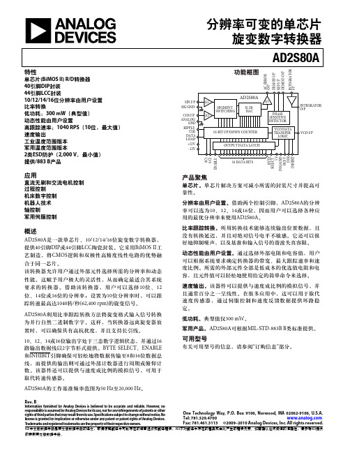
分辨率可变的单芯片 旋变数字转换器 AD2S80A
单芯片(BiMOS ll) R/D转换器 40引脚DIP封装 44引脚LCC封装 10/12/14/16位分辨率由用户设置 比率转换 低功耗:300 mW(典型值) 动态性能由用户设置 高跟踪速率:1040 RPS(10位,最大值) 速度输出 工业温度范围版本 军用温度范围版本 2类ESD防护(2,000 V,最小值) 提供/883 B产品
弧分 弧分 弧分 代码 代码
% FSD % FSD mV µV/°C % FSD V % rm s O /P kΩ V mA
1 mA负载 均值 过压保护 短路输出保护 10、12、14和16 双向自然二进制 逻辑LO至INHIBIT 逻辑LO使能位置 输出。逻辑HI输出处于 高阻抗状态 MS Byte DB1–DB8、 LS Byte DB9–DB16 LS Byte DB1–DB8、 LS Byte DB9–DB16 内部拉高 (100 kΩ)至+VS 10位 12位 14位 16位
高通MSM8909核心板XY8901_硬件设计手册_V1.1
SD2010 说明书
藤仓80S光纤熔接机

藤仓80S光纤熔接机
产品名称:藤仓80S光纤熔接机
规格:80S
产品备注:日本藤仓80S光纤熔接机
产品类别:光纤熔接机及配件
产品说明
80S引入了如下新机能:
自动开合防风盖以及加热器:
打破传统的熔接操作步骤,实现不可思议的最快7秒熔接和14秒加热
打开即可操作的一步式便携箱:
全新设计的内嵌式工作台,打开关闭皆可一步到位无需繁琐的准备
强光下也能看清的巨屏彩色显示屏:
更宽广的4.73英寸彩色液晶显示屏,在室外强光下亦能清晰可见
6向全方位防跌落概念:
全新的6向全方位防跌落设计,并同时具有卓越的防沙尘和防雨滴性能
适应高作业量的锂电池:
满充电后可以实现200次以上的熔接以及加热作业,能应对各种突发事件人性化的视频指导帮助:
随机附带的软件中特别搭载视频指导,人人都可以看懂
项目技术参数
适用光纤类型Single/SMF(G.652/657)、MMF(G.651)、NZDSF(G.655)
包层直径80-150μm
对应切割长度5mm to 16mm
熔接/加热模式总共100个熔接模式和30个加热模式
熔接损耗0.02dB(SM),0.01dB(MM),0.04dB(DSF) and 0.04dB(NZDS)。
K80S 用户手册4 names of part
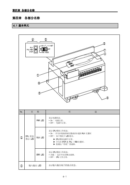
ERR LED
显示 CPU 模块工作状态。 闪烁 : 运行中自诊断出故障。 Off : CPU 工作正常。
②
输入输出 LED
显示输入输出端子的接点状态。
4-1
第四章 各部分名称
No.
⑤
②
⑥
③
④
4.2.3 模拟定时器模块
②
③
No.
名
称
① RUN LED
② 模拟量输入端子排
⑦
③
模拟量输入方式(电流/电压)选择跳线端 子
④ 模拟量输出端子
①
⑤ 提供外部电源(DC24V)端子
⑥ 扩展电缆
⑦ 扩展电缆联接端子
No.
名
称
① RUN LED
② 模拟定时器调节电阻
④
③ 扩展电缆
④ 扩展电缆联接端子
名
称
③ 电池盒
④ 模式选择键
⑤ 存储器操作开关 ⑥ RS232C 接口 ⑦ 扩展接口 ⑧ 外罩 ⑨ DIN 导轨卡 4.1.1 20 点基本单元
用
途
备用电池盒
选择基本单元的运行模式。 RUN : 运行用户程序。 STOP : 停止运行用户程序。 PAU / REM : 模式别具有不同意义。
▶PAUSE : 暂停用户程序。 ▶REMOTE : 遥控选择。
请参阅第五章内容。
联接外围设备(KGLWIN 等)用插口。
联接扩展单元用插口。
接线端子保护罩。
DIN 导轨卡。
④
⑤
①②
③
No.
名
称
用
DM9000中文手册

,011)被选 中
访问类型 高电平
是访问数据 端口;低电平 是访问地址 端口
字命令标志, 默认低电平 有效
当访问 外部数据存 储器是字或 双字宽度时, 被置位
100
INT
O
中断请求信 号
高电平 有效,极性能 修改
37~53 56
SD31~16
I/O
双字模式,高 16 位数据引 脚
注意:以上介质无关端口都内部自带 60K 欧姆的下拉电阻 处理器接口引脚
1
IOR#
I
2
IOW#
I
3
AEN#
I
处理器读命 令
低电平 有效,极性能 够被 EEPRO M 修改,详细 请参考对 EE PROM 内容 的描述
处理器写命 令
低电平 有效,同样能 修改极性
芯片选择,低
4
IOWAIT
O
14
RST
外部介质无 关接口发送 时钟
外部介质无 关接口发送 数据低 4 位
输出
TXD[2: 0]决定内部 存储空间基 址:TXD [2: 0]) * 10H +
300H
54
MDIO
I/O
外部介质无
关接口串行
数据通信
57
MDC
O
外部介质无 关串行数据 通信口时钟, 且与中断引 脚有关
该引脚 高电平时候, 中断引脚低 电平有效;否 则高有效
0 0 16 位
0 1 32 位
108 位
11未 定义
66
EECK
I
时钟信号
67
EECS
I/O
片选
也做 LE D 模式选择 引脚
A380e产品参数表

1600万色 TN FWQVGA (480*854) 4.5英寸
支持(电容)
5
颜色种类 屏幕种类 分辨率 尺寸 是否支持照像时 外屏显示功能
不支持 不支持 不支持 不支持
不支持
结构类 电性能
外观
按键 数据线 充电器 双卡
尺寸
颜色种类 颜色名称
重量
约131 mm×67 mm ×11.8 mm
首批上市1种 深邃黑 约140g(含电 池)
是否支持
是否支持(桌面 主题)
支持 星期一至星期日 支持
支持 1到30分钟 1次,2次,3次, 5次,10次
支持
存储位置(1、手
机;2、存储卡 3、手机/存储
手机/存储卡
卡)
存储照相的指定 文件夹名称
DCIM--Camera;
自拍形式
连拍 微距拍摄 相框拍摄模式
是否支持 分辨率 存储格式 可连续摄像时间
支持 1600*1200 3gp 取决于内存容量
存储位置(1、手
机;2、存储卡 3、手机/存储
手机/存储卡
是否支持后台播 放
MP3、AAC、MIDI 、WAV、AMR
支持
.lrc Music(可自定义 命名) 支持
支持
支持
内置是否支持FM 支持
内置是否支持FM 发射器
不支持
录音机
播放电影(视频 播放)
是否支持手机喇 叭(插入耳机情 况下) 不插耳机是否支 持FM 是否支持后台播 放 是否支持蓝牙立 体声
是否支持短信振 动
支持
支持(信息-菜单 键-设置-勾选“ 振动”)
彩信 支持格式
电子邮件
是否支持短信振 动关闭。
支持(信息-菜单 键-设置-不勾选 “振动”)
61580中文手册

特 征• 全集成MIL-STD-1553接口终端• 灵活的处理器/存储器接口 • 标准的4K ×16以及可选的 12K ×16或8K ×17RAM • 可选的RAM 奇偶产生/校验 • 自动BC 重试• 可编程的BC 间隔定时 • BC 帧自动重复• 灵活的RT 数据缓存 • 可编程的非法化 • 可任选的消息监控器 • 同时制RT/监控器模式通道A 通道B 参见命名信息以获得可用的存储器图1 ACE 模块图表1注:注1到注6适用于接收器差分电阻及差分电容的说明⑴该说明包括接收器及发送器(在内部是连在一起的)⑵阻抗的测试是直接在BU-65170/61580××混合器的管脚TX/RX A(B)及TX/RX A(B)之间进行的。
⑶假定混合器所有的电源及地输入端都被连接。
⑷该说明适用于上电及非上电两种情况⑸该说明假定是2V rms的平衡、差分、正旋输入的情况,适用频率范围是75KHz到1MHz。
⑹所给的最小电阻及最大电容参数在整个工作范围内都是满足要求的,但未经在整个工作范围内测试。
⑺假定共模电压的频率范围是直流到2MHz,在短截线一侧的隔离变压器的管脚上(直接耦合或变压器耦合)测得,以混合器的地为参考点。
使用的变压器必须是DDC推荐的或能提供相同的最小CMRR(共模抑制比)的其它变压器。
⑻对最小消息间间隔定时来说,其典型值在软件的控制下可以增加到(65535us 减去消息本身的时间),其单位增量是1us。
⑼是软件可编程的(4个选项),包括RT-to-RT暂停(发送指令的中间奇偶位到发送RT状态的中间同步位之间的时间)。
⑽是对+5V逻辑及收发器而言的,对通道A及通道B来说,是+5V。
⑾是从指令字的中间奇偶位过零点开始到RT状态字的中间同步位过零点为止进行测量的。
⑿对BU-65171、BU-61581、及BU-61586的说明与对BU-65170、BU-61580、及BU-61585的说明是分别完全相同的。
ZD52XXBS2中文资料(Cystech Electonics)中文数据手册「EasyDatasheet - 矽搜」
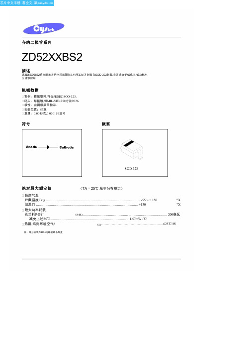
概要
SOD-323
绝对最大额定值
(TA = 25℃,除非另有规定)
最高气温
贮藏温度Tstg ............................................... .................................................. .. -55〜+ 150
°C
结温TJ ............................................................................................................. +150
°C
最大功率耗散
总功耗P合计
(注意).................................................. ......................................... 200毫瓦
3000
4000
5000
6000
7000
Reverse Voltage (mV)
ZD52XXBS2系列
CYStek产品规格
1600
7.0
5.0
3.5
20
6.2 ±5%
1000
7.0
5.0
4.0
20
6.8 ±5%
750
5.0
3.0
5.0
20
7.5 ±5%
500
6.0
3.0
6.0
20
8.2 ±5%
500
8.0
3.0
6.5
20
8.7 ±5%
600
8.0
H7008NL;中文规格书,Datasheet资料

Mechanicals
A IN
250-500 MHz
.039 0,991 .429 10,90 Dimensions: Inches mm
1:1
13 MX4-
USA 858 674 8100Germany 49 7032 7806 0Singapore 65 6287 8998Shanghai 86 21 62787060China 86 755 33966678Taiwan 886 3 4356768
.039 0,99
.552 .580 MAX 14,0 14,7
.050 1,27 11X .050 .550 = 1,27 13,97
22 X
.030 0,76
.429 10,90
.039 1,00
SUGGESTED LAND PATTERN
24X
.020 0,51 .050 1,27
.230 5,84 .040/1,05 12 SURFACES .035 0,89 .065 1,65
R P
Pulse Europe
M I L E
7 9 11 10 12
A IN
21 19 17 18 16 14 15 13
Y R
4X 75 W
2 3 4 5 6 7 8
(4X 0.1 µF)
EFI Capicitor (1000 pF, 2 kV)
For More Information:
Pulse Worldwide Headquarters Pulse China Headquarters Pulse North China
MSM7512B芯片资料

MSM7512B芯片资料MSM7512B芯片介绍课程:通信原理学号:姓名:能也较强。
因此,FSK调制技术在通信行业得到了广泛地应用,并且主要适用于用于低、中速数据传输。
二、MSM7512B芯片1、概述MSM7512B是OKI公司生产的调制解调器芯片,它采用FSK半双工调制方式,符合ITU-T V.23 标准,单电源+3~+5V工作,低功耗,稳定性好,具有片内回音消除电路,模拟输出可直接连入PSIN,并具有TIL接口,可方便地与数字系统及计算机系统相连。
特别适合低数据传输的场合。
有16DIP脚(产品名称: MSM7512BRS)及24SOP(产品名称: MSM7512BGS-K)脚两种封装形式。
2、原理框图2、引脚图及引脚说明序号引脚I/O 说明R S GS-VK1 1 VDD-接3~ 5V 电源2 3 AI │载波接收端。
3 5 AO 0 载波发送端。
4 6 EAI │外部信号输入端。
此管脚输入信号经7512B 放大后, 从AO 输出, 不用时悬空。
5 7 GND -接地。
6 8 X1 │接3158MHZ 晶振, 由于片内已有接地电容, 无需外接。
7 10 X2 08 12 CLK 0 输出3158MHZ 信号以供外部使用。
9 13 RD 0 串行数据接收端。
1 0 15 CD 0 载波检测端。
输出低电平为检测到FSK 载波或应答信号, 否则为高电平。
1117 XD │*串行数据发送端。
1 2 18 RS │*数据发送使能端。
输入低电平时允许7512B 进行数据发送, 高电平时不允许数据发送。
1 3 19 TEST│*芯片功能检测端。
接低电平时,进入内部功能检测状态。
1 4 20 MOD1│*工作模式选择开关。
1 5 22 MOD2│*1 6 24 AOG │*输出信号电平选择端。
接高电平时,输出信号电平典型值为210dbm; 接低电平时, 输出信号电平典型值为24dbm。
3、工作模式7512B有三种工作模式。
EM351中文资料(List Unclassifed)中文数据手册「EasyDatasheet - 矽搜」

收发器使用高效架构,超过由所施加动态范围要求 IEEE 802.15.4-2003标准由超过15分贝.集成接收通道滤波允许强大合作 存在与在2.4GHz频谱其他通信标准,如IEEE 802.11-2007和 蓝牙.集成稳压器,VCO,环路滤波器和功率放大器防护持外部元件数量 低.可选高性能无线模式(升压模式),可通过软件选择,以提高动态范围.
4-2
7.2配置
7-2
4.4集成MAC模块
4-2
7.3强制功能
7-3
4.5数据包跟踪接口(PTI)
4-2
7.4复位
7-4
4.6随机数发生器
4-2
7.5启动配置
7-4
5 ARM ® 皮质 TM-M3和内存
7.6 GPIO模式
7-5
模块
5-1
7.6.1模拟模式
7-5
7.6.2输入模式
7-6
5.1 ARM ® 皮质 TM-M3微处理器
AES128加密加速器
灵活ADC,UART / SPI / TWI串行
通信和通用定时器
24高度可配置GPIO与施密特
触发器输入
业界领先ARM
® 皮质 M3处理器
领先32位处理性能
高效Thumb-2指令集
运行在6,12,或24兆赫
灵活嵌套向量中断控制器
低功耗,先进管理
接收电流(W / CPU):26毫安
该EM35x提供许多先进电源管理功能,使电池寿命长.一个高频内部RC振荡器允许处理器核心醒来时 迅速开始执行代码. 各种深睡眠模式可低于1μA功耗,同时防护持RAM内容. 为支持用户自定义应用程序,片上外设包括UART,SPI,TWI,ADC,以及通用定时器,以及多达24个GPIO. 此外,集成电压调节器,电源接通复位电路,和睡眠定时器可用.
mb89f202中文资料

敞末让开端没。没有有使使用用的的I/O输末入端末进端入会输引出起状误态动后作并和把锁其定敞,开造;成如永其久在性输损入害状,态故,请就用按2照kΩ输或入以末上端的的电处阻理上方拉法或处下理拉该末等端I/。O
• N.C. 管脚的处置
(转下页)
6
系列 MB89202
(承上页) 管脚编号
SH-DIP32*1 SSOP34*3
24-27 26-29
21-23 32 10
23-25 34 10
管脚名称
P40/AN0 |
P43/AN3 P70-P72
VCC VSS
16
17
C
, — 16 22 :*1 DIP-32P-M06 :*2 FPT-34P-M03
(转下页)
2
系列 MB89202
(承上页)
产品型号 参数
MB89202
MB89F202
MB89V201
10 位 A/D 转换器 1A通0/D过位转精8换/度1功6×位能8定(个时转通器换道时/ 计间数:器1输2.出16或µ时s/1基2.定5 时MH器z计) 数器连续激活
Wild 寄存器
位8 × 2
:有 ×:无
MB89202 ×
MB89F202 ×
MB89V201 × ×
■ 产品间的差异
• 存储器容量
使用评价产品进行评价之前, 请先确认其与实际使用产品的差异。
• 屏蔽选项
产品不同,可以选择的项目和指定选项的方法也不同。选择之前,请查阅 “■ 屏蔽选项”一览表。
3
系列 MB89202
■ 管脚图
P33/EC
15
N.C.
16
C
BD7956FS中文资料

United Kingdom / London TEL : +44(1)908-282-666 France / Paris China / Hong Kong Shanghai Dilian Beijing Taiwan / Taipei Korea / Seoul Singapore Malaysia / Kuala Lumpur Philippines / Manila Thailand / Bangkok
TEL : +33(0)1 56 97 30 60 FAX : +33(0) 1 56 97 30 80 TEL : +852(2)740-6262 TEL : +86(21)6279-2727 TEL : +86(411)8230-8549 TEL : +86(10)8525-2483 TEL : +866(2)2500-6956 TEL : +82(2)8182-700 TEL : +65-6332-2322 TEL : +60(3)7958-8355 TEL : +63(2)807-6872 TEL : +66(2)254-4890 FAX : +852(2)375-8971 FAX : +86(21)6247-2066 FAX : +86(411)8230-8537 FAX : +86(10)8525-2489 FAX : +866(2)2503-2869 FAX : +82(2)8182-715 FAX : +65-6332-5662 FAX : +60(3)7958-8377 FAX : +63(2)809-1422 FAX : +66(2)256-6334
- 1、下载文档前请自行甄别文档内容的完整性,平台不提供额外的编辑、内容补充、找答案等附加服务。
- 2、"仅部分预览"的文档,不可在线预览部分如存在完整性等问题,可反馈申请退款(可完整预览的文档不适用该条件!)。
- 3、如文档侵犯您的权益,请联系客服反馈,我们会尽快为您处理(人工客服工作时间:9:00-18:30)。
5/17
元器件交易网
¡ Semiconductor
MSM518200
AC Characteristics (1/2)
(VCC = 5 V ±10%, Ta = 0°C to 70°C) Note 1, 2, 3, 11, 12
(RAS-only Refresh)
tRC = Min.
Power Supply Current (Standby)
RAS = VIH,
ICC5 CAS1, CAS2 = VIL, —
5
—
5
—
5 mA 1
DQ = enable
Average Power
RAS cycling,
Supply Current
Row Address Strobe Column Address Strobe Data Input/Data Output Output Enable Write Enable Power Supply (5 V) Ground (0 V) No Connection
Note : The same power supply voltage must be provided to every VCC pin, and the same GND voltage level must be provided to every VSS pin.
H
L
L
H
L
L
L
L
H
L
L
L
H
H
*: "H" or "L"
DQ Pin
DQ1
DQ2
High-Z
High-Z
High-Z
High-Z
DOUT High-Z DOUT
DIN Don't Care
DIN High-Z
High-Z
DOUT DOUT Don't Care DIN DIN High-Z
Function Mode
Standby Refresh DQ1 Read DQ2 Read DQ1, DQ2 Read DQ1 Write DQ2 Write DQ1, DQ2 Write
—
3/17
元器件交易网
¡ Semiconductor
MSM518200
ELECTRICAL CHARACTERISTICS
26/24-pin 300 mil plastic SOJ (SOJ26/24-P-300-1.27) (Product : MSM518200-xxSJ) 26/24-pin 300 mil plastic TSOP (TSOPII26/24-P-300-1.27-K) (Product : MSM518200-xxTS-K)
ICC6 CAS1, CAS2
— 70 — 65 — 60 mA 1, 2
(CAS before RAS Refresh)
before RAS
Average Power
RAS = VIL,
Supply Current
ICC7 CAS1, CAS2 cycling, —
60
—
55
—
50 mA 1, 3
¡ Semiconductor
PIN CONFIGURATION (TOP VIEW)
VCC 1 DQ1 2 DQ2 3
26 VSS 25 NC 24 CAS1
VCC 1 DQ1 2 DQ2 3
WE 4
23 CAS2
WE 4
RAS 5
22 OE
RAS 5
A11R 6
21 A9
A11R 6
MSM518200
Symbol VT IOS PD* Topr Tstg
*: Ta = 25°C
Recommended Operating Conditions
Parameter Power Supply Voltage Input High Voltage Input Low Voltage
Symbol VCC VSS VIH VIL
FEATURES
• 4,194,304-word ¥ 2-bit configuration • Single 5 V power supply, ±10% tolerance • Input : TTL compatible, low input capacitance • Output : TTL compatible, 3-state • Refresh : 4096 cycles/64 ms • Fast page mode, read modify write capability • CAS before RAS refresh, hidden refresh, RAS-only refresh capability • Multi-bit test mode capability • Package options:
2/17
元器件交易网
¡ Semiconductor
MSM518200
BLOCK DIAGRAM
RAS CAS1 CAS2
Timing Generator
Timing Generator
Column 10 Address
Buffers
A0 - A9
Internal Address Counter
DESCRIPTION
The MSM518200 is a 4,194,304-word ¥ 2-bit dynamic RAM fabricated in Oki's silicon-gate CMOS technology. The MSM518200 achieves high integration, high-speed operation, and low-power consumption because Oki manufactures the device in a quadruple-layer polysilicon/double-layer metal CMOS process. The MSM518200 is available in a 26/24-pin plastic SOJ or 26/24-pin plastic TSOP.
(Fast Page Mode)
tPC = Min.
Notes : 1. ICC Max. is specified as ICC for output open condition. 2. The address can be changed once or less while RAS = VIL. 3. The address can be changed once or less while CAS1, CAS2 = VIH.
Absolute Maximum Ratings
Parameter Voltage on Any Pin Relative to VSS Short Circuit Output Current Power Dissipation Operating Temperature Storage Temperature
xx indicates speed rank.
PRODUCT FAMILY
Family
MSM518200-60 MSM518200-70 MSM518200-80
Access Time (Max.) Cycle Time
Power Dissipation
tRAC tAA tCAC tOEA
(Min.)
元器件交易网
E2G0028-17-41
¡ Semiconductor ¡ Semiconductor
This versionM: SJaMn.5119892800 Previous version: May 1997
MSM518200
4,194,304-Word ¥ 2-Bit DYNAMIC RAM : FAST PAGE MODE TYPE
0 V £ VI £ 6.5 V;
Input Leakage Current ILI All other pins not –10 10 –10 10 –10 10 mA
under test = 0 V
DQ disable Output Leakage Current ILO 0 V £ VO £ 5.5 V
19 A8 18 A7 17 A6 16 A5 15 A4 14 VSS
26/24-Pin Plastic TSOP (K Type)
Pin Name
A0 - A9,
A10R, A11R RAS
CAS1, CAS2 DQ1, DQ2
ction
Address Input
A10R, A11R 2 Buffers coders
Word Drivers
Memory Cells
VCC
On Chip VBB Generator
VSS
FUNCTION TABLE
Input Pin
RAS CAS1 CAS2 WE
OE
H
*
*
*
*
L
H
H
*
*
L
L
H
H
L
L
H
L
H
L
L
L
L
H
L
L
L
H
L
H
L
Rating
Unit
–1.0 to 7.0
V
50
mA
1
W
0 to 70
°C
–55 to 150
°C
Min. 4.5 0 2.4 –1.0
