RS204L中文资料
Siemens SCALANCE XF204-2产品数据手册说明书

Product data sheet6GK5204-2BC00-2AF2 Product-type designation SCALANCE XF204-2SCALANCE XF204-2, FLAT,MANAGED IE SWITCH,4 X 10/100MBIT/S RJ45 PORTS,2 X 100MBIT/S FO PORTS,FAULT SIGNAL CONTACT WITH SET- BUTTON,REDUNDANT POWER SUPPLY,PROFINET-IO DEVICE, NETWORKMANAGEMENT,RED.- MANAGER INTEGRATED,INCL. MANUAL ON CD, C-PLUG OPTIONALTransfer rate / 110 Mbit/sTransfer rate / 2100 Mbit/sNumber of electrical/optical connections• for network components or terminal equipment / maximum6Number of electrical connections• for network components and terminal equipment4• for signaling contact1• for power supply1• for redundant power supply1Design of the electrical connection• for network components and terminal equipment RJ45 port• for signaling contact2-pole terminal block• for power supply4-pole terminal blockNumber of optical interfaces / for optical waveguide / at 100 Mbit/s2Design of optical interface / for optical waveguide / at 100 Mbit/s BFOC sockets (multimode up to 5 km)Connectable optical power relative to 1 mW• of the transmitter output-19 … -14 dBOptical sensitivity relative to 1 mW / of the receiver input / minimum-34 dBAttenuation / of fiber-optic cable transmission link / minimum0 dBnecessaryRange / at the optical interface / depending on the optical fiber used0 … 5 kmdesign of the removable storage / C-PLUG YesOperating voltage / of signaling contacts / at DC / rated value24 VOperating current / of signaling contacts / at DC / maximum0.1 AType of / supply voltage DCSupply voltage / external24 V• minimum18 V• maximum32 VProduct component / fusing at power supply input YesType of fusing / at input for supply voltage1,1 A / 33 VConsumed current / maximum0.22 AActive power loss / at 24 V / for DC 5.28 WAmbient temperature• during operating-40 … +60 °C• during storage-40 … +70 °C• during transport-40 … +70 °C• Comment If the IE switch XF 200 is installed horizontally a maximum ambienttemperature of +40 °C is permitted95 %Relative humidity / at 25 °C / without condensation / during operating/ maximumProtection class IP IP20Design FlatWidth75 mmHeight125 mmDepth73 mmNet weight0.25 kgMounting type• 35 mm DIN rail mounting Yes• wall mounting No• S7-300 rail mounting No50Cascading in the case of a redundant ring / at reconfiguration time of<\~0.3\~sCascading in cases of star structuring Any (depending only on signal propagation time)Product function• CLI Yes • web-based management Yes • MIB support Yes • TRAPs via email Yes • Configuration with STEP 7Yes • Port mirroring Yes • for IRT / PROFINET IO switch No • PROFINET IO diagnosis Yes • switch-managed Yes Protocol / is supported• Telnet Yes • HTTP Yes • HTTPS Yes • TFTP Yes • FTP Yes • BOOTP No • SNMP v1Yes • SNMP v2Yes • SNMP v3Yes • DCP Yes • LLDP Yes Identification & maintenance function• I&M0 - device-specific information Yes • I&M1 – higher level designation/location designation YesProduct function• Port diagnostics Yes • Statistics Packet Size Yes • Statistics packet type Yes • Error statistics YesProduct function / DHCP client YesProduct function• Ring redundancy Yes • Redundancy manager Yes • Standby redundancy No • High Speed Redundancy Protocol (HRP)Yes • Media Redundancy Protocol (MRP)Yes• Parallel Redundancy Protocol (PRP)No• Passive listening YesProtocol / is supported / PRP YesProtocol / is supported / SSH YesProduct function / SICLOCK support YesProtocol / is supported• NTP No• SNTP YesStandard• for EMC / from FM FM3611: Class 1, Division 2, Group A, B, C, D / T4, CL.1, Zone 2,GP. IIC, T4• for hazardous zone EN 60079-0: 2006, EN60079-15: 2005, II 3 (2) G Ex nA [op is] IICT4, KEMA 07 ATEX 0145 X• for safety / of CSA and UL UL 60950-1, CSA C22.2 No. 60950-1• for hazardous area / of CSA and UL ANSI / ISA 12.12.01, CSA C22.2 No. 213-M1987, CL. 1 / Div. 2 /GP. A, B, C, D T4, CL. 1 / Zone 2 / GP. IIC, T4• for emitted interference EN 61000-6-4:2001 (Class A)• for interference immunity EN 61000-6-2:2001Verification of suitability EN 61000-6-2:2001, EN 61000-6-4:2001• CE mark Yes• C-Tick Yes• KC approval Yes• Railway application in accordance with EN 50155No• Railway application in accordance with EN 50124-1NoMarine classification association• American Bureau of Shipping Europe Ltd. (ABS)No• Bureau Veritas (BV)No• Det Norske Veritas (DNV)No• Germanische Lloyd (GL)No• Lloyds Register of Shipping (LRS)No• Nippon Kaiji Kyokai (NK)No• Polski Rejestr Statkow (PRS)NoInternet-Link• to website: Industry Mall /industrial-controls/mall• to website: Industrial communication /simatic-net• to website: Information and Download Center /automation/net/catalog• to website: Image database /bilddb • to website: CAx Download Manager /cax• to website: Industry Online Support letzte Änderung:Jul 3, 2014。
卫星数字电视接收机技术要求

卫星数字电视接收机技术要求Specification of measurement for satellitedigital television receiver国家广播电影电视总局2000-03-17批准2000-04-01 实施17表1 使用和显示功能(完)复合视频信号输出路数≥1路≥1路音频立体声道输出路数≥1路≥1路模拟分量视频输出Y/U/V Y/C数据通道(≥19.2kbps) ≥1路传输码流输出接口任选4 信源解码要求信源解码条件:符合MPEG-2主级主类传送码流格式;单路视频压缩码率:2 ~ 15Mbps连续可调;图像分辨率:PAL制,随发端信号可调。
5 信道解调参数a)符合MPEG-2传送码流格式;b)解调方式:QPSK解调;c)RS编码:RS(204,188,T=8);d)卷积交织深度:I=12;e)卷积编码比率:1/2,2/3,3/4,5/6,7/8可变;约束长度:K=7;f)升余弦平方根滤波滚降系数:0.35。
6 信道性能指标a)输入L-BAND的RF频率适应范围:950 ~ 2150MHz(可降低至950 ~ 1750MHz);b)捕捉信号的频率范围:±2.5MHz;c)输入电平适应范围: -65 ~ -30dBm;d)输入反射损耗:≥7dB;e)二本振泄漏:≤-65dBm;f)LNB极化切换电压范围:12 ~ 24V可调,Imin=350mA;g)可同时用于SCPC和MCPC方式;h)符号率:2 ~ 30MS/s 或 2 ~ 45 MS/s。
7 Eb/No 门限值a)定义18在卫星数字电视传输时,接收端的Eb/No值下降到某一值时,维特比译码输出误码率为2.0E-4,此时的Eb/No值即为门限值。
b)技术指标Eb/No门限值≤5.5dB(FEC=3/4)。
8 视音频系统指标表2 卫星接收机视音频性能指标(专业型和普及型)序号技术参数单位要求备注1 数据输出误码率≤1.0E-11 —2 视频幅频特性dB ±0.5≤+0.5, ≥-1.0≤+0.5, ≥-4≤4.8MHz4.8~5.0MHz≥5.5MHz3 视频信杂比(S/N)dB≥56(加权值)—4K因子%±3 —5 色度/亮度增益差(ΔK)%±5 —6 色度/亮度时延差(Δτ)ns±30 —7 亮度非线性失真%≤5 —8 微分增益失真(DG)%±5 —9 微分相位失真(DP)度±5 —10 行同步前沿抖动ns≤20p-p11 视频输出反射损耗dB≥26 —12 带外寄生输出dBm≤-40 —13 音频频率响应dB ≤+1.0, ≥-2.0±0.5≤+1.0, ≥-3.020Hz~60Hz60Hz~18kHz18kHz~20kHz14 音频信噪比dB≥70(不加权)—15 音频总谐波失真%1—16 左右声道电平差dB≤0.5 60Hz~18kHz17 左右声道相位差度≤5 60Hz~18kHz18 左右声道串扰dB≤-70 —9 信号接口形式a)输入连接方式阻抗:75Ω;RF端口:F型;b)数字信号输出形式19数据输出(≥19.2kbps)端口:DB-9阴性;传输码流应符合DVB标准要求;传输码流输出:SPI(并行)或 ASI(串行);c)复合视频信号图像基带:5.5MHz;信号极性:正极性;亮度信号:0.7Vp-p ± 20mVp-p;同步信号:0.3Vp-p ± 9mVp-p;d)图像信号输出形式视频输出:PAL-D复合视频信号和数字分量信号;输出阻抗:75Ω;模拟分量输出端口:Y/U/V(专业型)或Y/C(普及型);复合视频输出端口:BNC座或RCA;e)声音信号输出形式音频输出:不少于一路立体声输出,并带有监听输出(专业型);不少于一路立体声输出(普及型);标称输出电平:0 dBm ± 3 dBm可调,最大不失真输出电平:≥ +9 dBm (专业型);-6 dBm ± 3 dBm可调(普及型);阻抗:600Ω平衡或不平衡型(专业型);低阻(普及型);输出端口:XLR 或 RCA(专业型);RCA(普及型);f)射频输出形式(此功能任选)射频输出:PAL-D调制;输出电平:60 ~ 80dBμV;输出阻抗:75Ω;输出端口:F型。
计算机测控技术
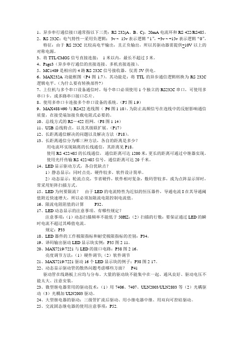
1、异步串行通信接口通常指以下三类:RS-232(A、B、C),20mA电流环和RS-422/RS485。
2、RS-232C:电气特性—采用负逻辑:-3v ~ -15v表示逻辑“1”,+3v ~ +15v表示逻辑“0”。
特征:由于RS-232C比较高电平输出,且正负输出,所以其驱动器需提供+10V以上的对称电源。
3、将TTL/CMOS信号直接连接:1米以内,最长不超过5米。
4、Page3(异步串行通信的直接连接、多机直接连接)。
5、MC1489是相应的4路RS-232C信号接收器,仅需5V供电。
6、MAX232A功能框图(P4图1.7)。
其功能是:将TTL的异步通信逻辑转换为RS-232C 逻辑电平。
(为什么要有转换部件?)7、上位机与多个串口设备通信时,每个串口必须使用1个独立的RS232C串口,可使用多串口卡,或多路串口接口芯片。
8、使用多串口卡连接多个串口设备的系统。
(P5图1.9)9、MAX488/490与RS422连线图(P6图1-10)。
为防止高频信号在连线中的反射影响通信质量,在接受端加接负载电阻式必要的。
10、总线方式的RS-422组网。
(P8图1-14)11、USB总线特点,以及其级联扩展。
(P17)12、长距离通信解决的问题以及解决方法(P18)。
13、长距离通信分为哪三种方法,各自的距离是多少?-用电流环实现隔离的长线通信,其距离见P18。
-使用RS-422/485的长线通信,通信距离可达1200米,更长的距离可通过中继器实现。
-使用光纤传输RS-422/485信号,通信距离可达20千米。
14、LED显示驱动方式,各自优缺点?1)静态显示:同时点亮,硬件较多,软件设计简单。
2)动态显示:轮流点亮,节省硬件,软件相对复杂,数码管较多,或为点阵显示屏时,常采用矩阵扫描方式。
15、LED为何要限流?由于LED的电流特性为近似的恒压器件,导通电流I在其导通阈值附近快速增大,所以必须加限流电阻控制电流值。
CST配件中文
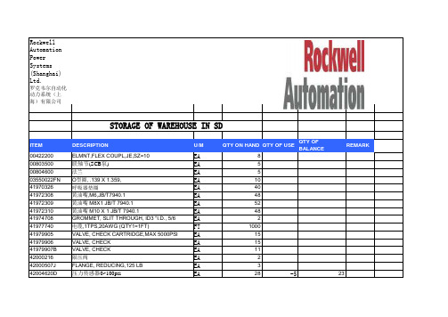
REMARK 23
42004620F 42004620H 42004628D 42004628F 42004628H 42004628I 42004629C 42004629D 42004629G 42004629J 42004629K 42004629L 42006201 42006203 42008151 42100220 61160601 61160603 61160604 61160605 61160606 61160620 61160629 61160630 61160631 61160632 61160633 61160634 61160638 61160641C
EA
弹性节5 "
EA
CST总成 2X1120KV
EA
冷却泵组件, W/ 660/1140 18
EA
冷却泵组件, W 380V/660V
EA
比例阀放大器,0-600mA,
EA
比例阀放大器 低压
EA
比例阀放大器 高压
EA
比例阀 低压
EA
比例阀 高压
EA
公制的扇叶轮毂,280K--750K
EA
公制的扇叶轮毂,1120K
模拟量隔离栅,GS8064
EA
61163119BA 陶瓷滤芯
EA
61163139A
61163146代替
EA
61163139G
Байду номын сангаас
过滤器旁路堵头
EA
61163139L
10μ滤芯(旧系统)
EA
61163139T
ASSY,FLTR,D/P SWTCH,DIN
EA
61163139V
25μ滤芯 系统滤芯
RS203资料

AND ELECTRICAL CHARACTERISTICS
• • •
Ratings at 25OC ambient temperature unless otherwise specified Single Phase, half wave, 60Hz, resistive or inductive load For capacitive load derate current by 20%
VRRM VRMS VDC I(AV) IFSM I2t VF IR CJ RθJc TJ TSTG
RS201 RS202 RS203 50 100 200 35 70 140 50 100 200
RS204 RS205 RS206 RS207 UNIT 400 600 800 1000 Volts 280 420 560 700 Volts 400 600 800 1000 Volts 2.0 50 10 1.0 10 0.5 20 Amps Amps A2s Volts µA mA pF
O
28 (-65 to +150) (-65 to +150)
C/W O C O C
Notes:
1. Unit mounted on PC board with 0.47” x 0.47” (12mm x 12mm) copper pads, 0.375 (9.5mm) lead length.
Sep-03, Rev A
Micro Electronic Instrument Inc.
元器件交易网
RATINGS AND CHARACTERISTIC CURVES RS201 THRU RS207
Sep-03, Rev A
CHARGEBDPDF资料下载_CHARGEBD:chargebdpdf资料下载_chargebd

RER70I08D-5RFB - RER70JE-6327 - RER70K2 - RER70LT1 - RER70M1GO24L253B - RER70N06 - RER70N1002 - RER70R100R -RER70R301 - RER70R301M - RER70S2R49R - RER710 - RER7100110 - RER71001-10 - RER7100113 - RER71001-13 - RER7100116 -RER71001219 - RER71001-219 - RER71001231 - RER71001-231 - RER71001249 - RER7100125 - RER71001-25 - RER71001255 -RER71001-255 - RER71001255ERICSSON - RER71001-255ERICSSON - RER7100137 - RER71001-37 - RER7100155 - RER71001-55 - RER7100167 - RER71001-67 - RER710037 - RER7101SYCBE - RER71901-42 - RER74F1001R - RER74F48R30W - RER74F48R7R - RER75 - RER7511R8 - RER7511R8R - RER7515251 - RER751525-1 - RER75152547 - RER751525-47 - RER751OROM - RER7524R90 - RER75262525 - RER752625-25 - RER75262525C - RER752625-25C - RER753010R - RER7534R0R - RER753R40R - RER754R02R - RER75514421 -RER7551442-1 - RER755144222 - RER7551442-22 - RER75514422L - RER7551442-2L - RER755144233 - RER7551442-33 - RER755144247 - RER7551442-47 - RER755144312 - RER7551443-12 - RER755144322 - RER7551443-22 - RER75514441 - RER7551444-1 - RER755144433 - RER7551444-33 - RER755144447 - RER75514451 - RER7551445-1 - RER755144556 - RER7551445-56 - RER755144582 - RER756980M - RER75E6811R30M - RER75E-X - RER75F01R0R - RER75F0R75 - RER75F0R75R - RER75F100 - RER75F1001 - RER75F1001M -RER75F1001P - RER75F1001R - RER75F1001RC02 - RER75F1002 - RER75F1002M - RER75F1002R - RER75F102 - RER75F102R -RER75F1050 - RER70GR500IC供应:BIOS06716E、10NF121050V10、SMD59C11SNSO-26、RS-1-216R8、SR212C682MAT、BIOS067-16E、10NF-1210-50V-10、SMD59Kohm-1 116W、RS1217、SR212C821KAA、BIOS067177-08、10NF-1210-50V-10 、SMD5A-125V、RS-12-17、SR212C822KAA、BIOS-0677、10NF-1210-50V-5 -、SMD5C100835、RS12178、SR212C822KAATR、BIOS-067-77-08、10NF121050V5C0G、SMD5C1008-35、RS-1-2-178、SR212C822KAT。
RS206L中文资料
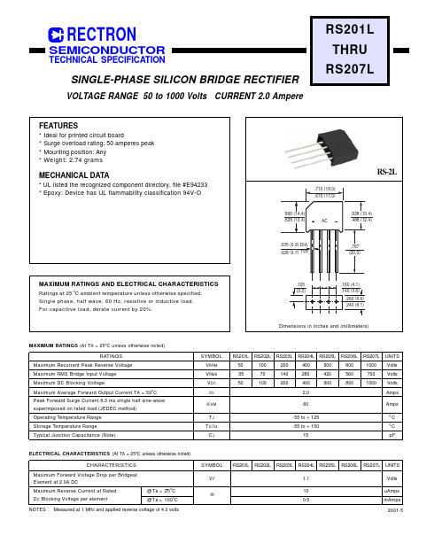
.125 (3.2)
.160 (4.1) .140 (3.6) .260 (6.6) .240 (6.1)
Dimensions in inches and (millimeters)
MAXIMUM RATINGS (At T A = 25 oC unless otherwise noted) RATINGS Maximum Recurrent Peak Reverse Voltage Maximum RMS Bridge Input Voltage Maximum DC Blocking Voltage Maximum Average Forward Output Current T A = 50oC Peak Forward Surge Current 8.3 ms single half sine-wave superimposed on rated load (JEDEC method) Operating Temperature Range Storage Temperature Range Typical Junction Capacitance (Note) SYMBOL VRRM VRMS VDC IO I FSM TJ TSTG CJ RS201L 50 35 50 RS202L 100 70 100 RS203L RS204L RS205L 200 140 200 400 280 400 2.0 60 -55 to + 125 -55 to + 150 15 600 420 600 RS206L 800 560 800 RS207L 1000 700 1000 UNITS Volts Volts Volts Amps Amps
INSTANTANEOUS REVERSE CURRENT, (uA) INSTANTANEOUS FORWARD CURRENT, (A)
GNDRDBSDBSDARDAF...

目录第一章 产品概述.........................................................................................................................1 1.1 功能 ...............................................................................................................................1 1.2 一般规格 ........................................................................................................................1 1.3 各部分名称.....................................................................................................................2 1.4 外型尺寸及安装方法 ......................................................................................................4第二章 编辑软件 MD20...............................................................................................................5 2.1 MD20基本概述 ..............................................................................................................5 2.2 编辑用户画面 .................................................................................................................5 2.3 保存工程 ......................................................................................................................29 2.4 下载画面 ......................................................................................................................30 2.5 导入旧工程..................................................................................................................30第三章 操作方法.......................................................................................................................32 3.1 联机通讯 ......................................................................................................................32 3.2 切换画面 ......................................................................................................................32 3.3 系统口令 ......................................................................................................................32 3.4 修改数据 ......................................................................................................................33 3.5 开关量控制...................................................................................................................34第四章 与 PLC 的连接方法 .......................................................................................................35 4.1 三菱 FX 系列 ................................................................................................................35 4.2 西门子 S7-200 系列 .....................................................................................................36 4.3 欧姆龙 C 系列 ..............................................................................................................36 4.4 OMRON CP1H 系列 ............................................................................................................... 37 4.5 施耐德 NEZA/TWIDO 系列 ..........................................................................................39 4.6 台达 DVP 系列 ............................................................................................................40 4.7 松下 FP 系列 ................................................................................................................40 4.8 LG Master-K CNet 系列 ...............................................................................................41 4.9 LG 系列 Modbus 协议 ................................................................................................42 4.10 LG Master-K 120S 编程口通讯 .................................................................................43 4.11 FACON 永宏系列 .......................................................................................................43 4. 12 光洋 S 系列 ..............................................................................................................44 4.13 ECOSTEP 系列 ........................................................................................................45 4.14 AB Micrologix 系列.....................................................................................................46 4.15 MODBUS RTU/ASCII/EMERSON/RTU EXTEND .....................................................47 4.16 MODBUS SERVER ...................................................................................................48 4.17 自由协议 ........................................................................................................49 4.18 SAIA PCD S-BUS 协议 ..............................................................................................50 4.19 VIGOR PLC...............................................................................................................51 4.20 EMERSON EC20 系列 PLC ......................................................................................51Created with novaPDF Printer (). Please register to remove this message.文本显示器MD204L V4 用户手册4.21 KEYENCE KV 系列 PLC............................................................................................52 4.22 KEYENCE KV 系列 PLC...................................................................... 错误!未定义书签。
204中文说明书

GSW型光栅数显系统(中文液晶提示)使用说明书成都远山机电产品有限公司尊敬的用户:欢迎您使用远山机电最新开发液晶中文提示的GSW 光栅数显系统,远山机电光栅系统广泛用于铣床、磨床、镗床、线切割、车床、电火花加工设备,它的应用有助于提高生产效率、显示直观、操作方便、精度准确、重复性稳定,是模具制造业、机械加工业、精密测量仪器必不可少的装置。
本系统设置多种智能化功能,如SDM300点记忆、等分圆和椭圆、斜面加工、R的加工8个面选择、分中功能的用法,还配置了计算器,等等功能,使用起来十分方便。
应用远山机电的光栅数显系统,不须经过培训,按照中文使用说明书每步提示一看就懂。
最适合刚使用操作的新手,对于熟练的操作者更是得心应手。
要想了解有关的细节请阅读使用说明书。
安全注意事项:打开产品包装,取出箱内数显表与电子尺相接,然后插上电源检查显示是否正常。
①开箱后检查外观是否完好,若有故障应立即联系本公司销售部,切勿自行拆卸维修。
②本装置使用110V~220V,50Hz~60Hz的交流电源,电源插头是带有接地脚的三芯电源插头。
三芯电源插座地线一定要接地牢靠。
③用户不可以自行打开机壳修理,表内有高压电源以免造成人员伤害。
④本机壳是采用ABS工程塑料,不具防爆高温的环境中使用。
⑤平时不用时请关闭电源,可延长本产品使用时间。
⑥在雷雨天气时应关闭或拔掉电源线以免高压雷击电网引起表的电源电压突然猛增高而烧毁表内电源,给用户带来不必要的损失。
日常维护:①每天下班时,清洁时请关闭电源。
②用干布或毛刷擦拭数显表或电子尺防护外壳。
③不能用甲苯或乙醇清洗外壳。
④数显表外壳或显示窗的污迹可用洗衣粉和水搅匀用毛巾扭干水擦拭。
承诺:本公司产品如因用户使用操作不当造成电子尺和数显表的损坏,特别是因碰撞造成产品外观或内部损坏,或自行拆下电子尺限位,造成因超行程把尺撞坏,需本公司维修服务的,本公司要收取适当的材料费和维修费。
面板按键说明GSW-204GSW-304目录功能项目 (7)清零 (8)输入坐标 (8)公/英制显示 (8)ABS/INC坐标 (9)自动分中 (10)RI(寻找师傅零位) (11)半径/直径 (11)计算器 (11)SDM300组记忆 (12)圆周分孔 (18)椭圆分孔 (21)斜线分孔 (25)圆弧加工 (27)平滑圆弧加工 (35)斜面加工 (39)电火花加工 (42)基本参数 (45)高级用户 (46)光栅线位移传感器 (48)光栅线位移动传感器行程和安装尺寸 (51)安装示图 (52)故障分析与处理 (53)GSW-中文提示光栅数显表,中文辅助显示智能表,采用高科技软件电子技术,功能多、易操作、可靠耐用,使机械加工的必备产品。
SCALANCE XF204产品说明书
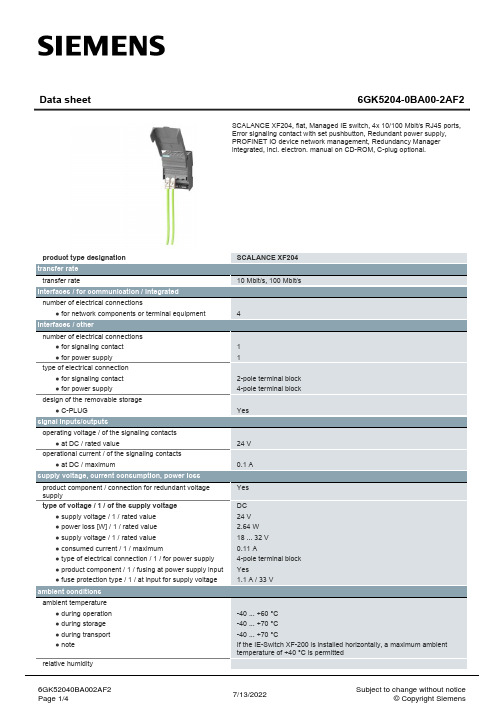
certificate of suitability
EN 61000-6-4:2001
● C-Tick
Yes
● KC approval
Yes
● railway application in accordance with EN 50155
No
● railway application in accordance with EN 50124-1
Data sheet
6GK5204-0BA00-2AF2
SCALANCE XF204, flat, Managed IE switch, 4x 10/100 Mbit/s RJ45 ports, Error signaling contact with set pushbutton, Redundant power supply, PROFINET IO device network management, Redundancy Manager integrated, incl. electron. manual on CD-ROM, C-plug optional.
● media redundancy protocol (MRP) with redundancy Yes manager
● Parallel Redundancy Protocol (PRP)/operation in
Yes
the PRP-network
● Parallel Redundancy Protocol (PRP)/Redundant
● from CSA and UL
ANSI / ISA 12.12.01, CSA C22.2 No. 213-M1987, CL. 1 / Div. 2 / GP. A, B, C, D T4, CL. 1 / Zone 2 / GP. IIC, T4
R204ABAQUS资料-HEAT-WK03-ReactorFilm

Workshop 3Reactor Pressure Vessel: Film Conditions andInitial Temperature FieldKeywords VersionNote: This workshop provides instructions in terms of the Abaqus Keywords interface. If you wish to use the Abaqus GUI interface instead, please see the “Interactive” version of these instructions.Please complete either the Keywords or Interactive version of this workshop.GoalsWhen you complete this workshop, you will be able to:•Define surface-based film conditions•Use an amplitude specification for thermal loading•Define initial temperature fields•Create a surface by combining two or more existing surfaces of the same type IntroductionIn this workshop you will continue working on the reactor vessel model (from Workshop 2) to specify the thermal loads and initial temperature condition. The thermal response of the model is driven entirely by thermal loading through film coefficients (no temperature boundary condition is applied in the model). Figure W3–1 shows the surfaces where the thermal loads should be applied. The reactor is initially at 70 °F. The outer surfaces of the reactor vessel assembly are exposed to air at 70 °F, with a film coefficient of 0.035Btu/h/in2/°F. The inner surfaces are in contact with water and have a film coefficient of 0.70 Btu/h/in2/°F. At steady state, the inlet water temperature is 508 °F and outlet water temperature is 538 °F. During a rapid cool down in the fuel core, a 30 °F outlet temperature drop occurs over a 45 second period, while the inlet temperature remains the same.W3.2Figure W3–1. Thermal loading regionsPreliminariesFrom the working directory for this workshop:../heat_transfer/keywords/reactor-htopen the input file w_reactor_ht.inp using your text editor. You will now add the surface-based film condition and initial temperature field definitions described earlier. Note: Since this model will be used in subsequent workshops to build the complete model and perform the analysis, it is important that you use the data stated and notdeviate from the workshop instructions. Otherwise, you may find it difficult to complete the subsequent workshops.Defining film conditions and the initial temperature fieldBefore creating film conditions, you will first specify amplitude curves that will be used to define the variation of the sink temperature and then create assembly-level surfaces that define the thermal loading regions.OutsideCold side water(inlet)Hot side water (outlet)Elevation = 220 inW3.3 1.Create an amplitude curve that describes the time-variation of the inlet watertemperature. Use the total time as the time span. Note that amplitude definitions are defined at the model level (i.e., after the *END ASSEMBLY option andbefore the first *STEP option). The required option is:*AMPLITUDE, NAME=water-inlet, TIME=TOTAL TIME0., 508., 1., 508., 1801., 508.2.Create another amplitude curve that describes the variation of the outlet watertemperature. Similarly, use the total time as the time span. The required option is: *AMPLITUDE, NAME=water-outlet, TIME=TOTAL TIME0., 538., 1., 538., 46., 508., 1801., 508.Note that the part-level surfaces and sets described in the previous workshop are available for use at the assembly level. In this model many of these surfaces will take the same “attributes.” Therefore, to avoid defining attributes on every surface, you can merge ones that will take common attributes into a single surfacedefinition and then define the attribute on the merged surface. Abaqus allowscreating a combined surface using the COMBINE=UNION parameter on the*SURFACE option (the surfaces being combined must be the same type; i.e., an element-based surface can be combined with another element-based surface, but not with a node-based surface).3.Create an assembly-level surface by combining all part-level surfaces that are incontact with hot side water (see Figure W3–1). The required option is givenbelow. This option must appear between the *ASSEMBLY and *ENDASSEMBLY options.*SURFACE, COMBINE=UNION, NAME=inner-hothead-1.inner-hot, seal-1.inner, vessel-1.inner-hotNote the naming convention of a part-level surface when used at the assembly level. The surface head-1.inner-hot refers to the part-level surface inner-hot of the part instance head-1, the surface seal-1.inner refers to the part-level surface inner of the part instance seal-1, etc.4.Create an assembly-level surface by combining all part-level surfaces that areexposed to air (see Figure W3–1). The required option is given below. A text file named w_reactor_ht_surfaces.txt is provided with this information. You may copy and paste from this file.*SURFACE, COMBINE=UNION, NAME=outerSurfacefull_bolt-1.ends, full_bolt-1.shankfull_bolt-2.ends, full_bolt-2.shankfull_bolt-3.ends, full_bolt-3.shankfull_bolt-4.ends, full_bolt-4.shankhalf_bolt-1.ends, half_bolt-1.shankhalf_bolt-2.ends, half_bolt-2.shankW3.4 full_nut-1.outer, full_nut-1.topfull_nut-2.outer, full_nut-2.topfull_nut-3.outer, full_nut-3.topfull_nut-4.outer, full_nut-4.topfull_nut-5.outer, full_nut-5.topfull_nut-6.outer, full_nut-6.topfull_nut-7.outer, full_nut-7.topfull_nut-8.outer, full_nut-8.tophalf_nut-1.outer, half_nut-1.tophalf_nut-2.outer, half_nut-2.tophalf_nut-3.outer, half_nut-3.tophalf_nut-4.outer, half_nut-4.tophead-1.outer,seal-1.outer,vessel-1.outer5.Specify the film conditions on the surfaces indicated in Figure W3–1. The firstfilm condition is defined on the reactor inner surfaces that are on the hot water side, varying with time by referring to the amplitude water-outlet. The second film condition is defined on the reactor inner surfaces that are on the cool water side, varying with time by referring to the amplitude water-inlet. The third film condition is defined on the reactor outer surfaces that are exposed to air. Note that film conditions are defined at the model level. The required options are:Note: In this workshop the time unit is seconds. However, the given filmcoefficients use hours as the time unit. Before entering the data, you need toconverts the time units for the film coefficients.** Film conditions on inner surfaces:** k = 0.7/3600 Btu/sec/in^2/F*SFILM, AMPLITUDE=water-outletinner-hot, F, 1., 0.000194444*SFILM, AMPLITUDE=water-inletvessel-1.inner-cool, F, 1., 0.000194444**** Film condition on outer surfaces** k = 0.035/3600 Btu/sec/in^2/F*SFILMouterSurface, F, 70., 9.72222e-06You will next define the initial temperature for the model.6.Specify an initial temperature of 70 °F for the entire model. The node set ALL-Nodes includes all nodes of the entire model. Note that initial conditions aredefined at the model level. The required option is:*INITIAL CONDITIONS, TYPE=TEMPERATUREALL-Nodes, 707.Save all changes and close the input file.。
AD204资料
31 +15V DC 32 POWER
DEMOD ±5V F.S.
38
HI LO VOUT
37
IN COM +VISO OUT 6 –VISO OUT 5
RETURN
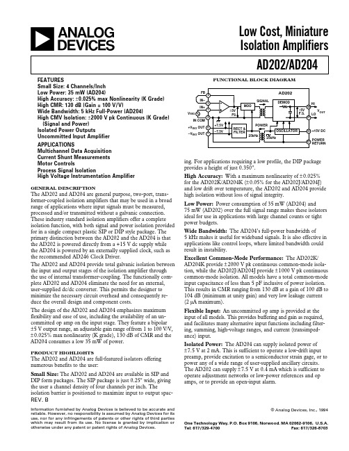
ing. For applications requiring a low profile, the DIP package provides a height of just 0.350". High Accuracy: With a maximum nonlinearity of ± 0.025% for the AD202K/AD204K (± 0.05% for the AD202J/AD204J) and low drift over temperature, the AD202 and AD204 provide high isolation without loss of signal integrity. Low Power: Power consumption of 35 mW (AD204) and 75 mW (AD202) over the full signal range makes these isolators ideal for use in applications with large channel counts or tight power budgets. Wide Bandwidth: The AD204’s full-power bandwidth of 5 kHz makes it useful for wideband signals. It is also effective in applications like control loops, where limited bandwidth could result in instability. Excellent Common-Mode Performance: The AD202K/ AD204K provide ± 2000 V pk continuous common-mode isolation, while the AD202J/AD204J provide ± 1000 V pk continuous common-mode isolation. All models have a total common-mode input capacitance of less than 5 pF inclusive of power isolation. This results in CMR ranging from 130 dB at a gain of 100 dB to 104 dB (minimum at unity gain) and very low leakage current (2 µA maximum). Flexible Input: An uncommitted op amp is provided at the input of all models. This provides buffering and gain as required, and facilitates many alternative input functions including filtering, summing, high-voltage ranges, and current (transimpedance) input. Isolated Power: The AD204 can supply isolated power of ± 7.5 V at 2 mA. This is sufficient to operate a low-drift input preamp, provide excitation to a semiconductor strain gage, or to power any of a wide range of user-supplied ancillary circuits. The AD202 can supply ± 7.5 V at 0.4 mA which is sufficient to operate adjustment networks or low-power references and op amps, or to provide an open-input alarm.
YD204LV2使用手册
7
8
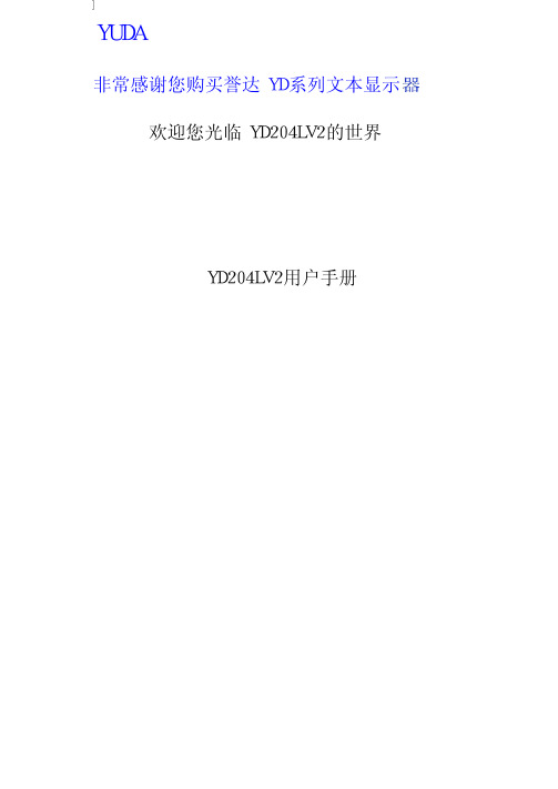
2-3新建工程 按 键或击活[文件] >[新建工程]命令,屏幕中弹出PLC机型选择对话窗:
注意在选择了正确的PLC后,还需要进行通讯端口的设置,设定的画面如下:
PLC类型 根据显示器通讯对象,选择PLC机型。YD20下载面时,将指定的PLC通讯协议和画 面数据一同传送给YD204LV2显示器,显示器工作时,即通过此协议和PLC通讯。
2
3
1-3各部分名称 YD204LV2的正面除液晶显示窗之外,还有 20个薄膜开关按键,触摸手感好、使用寿命
长、安全可靠。所有的 20个按键除了具备基本功能外,还能被设定成特殊功能按键,直 接完成画面跳转,开关量设定等功能。
YD204LV2可编程文本显示器的前面板如下图:
所有 20个按键都能被用户定义成特定功能.如 Bit置位、Bit复位、画面跳转等.如果未定 义成特殊功能则只能执行基本功能。基本功能包括设定寄存器数值、初始画面复位、前页后 页画面跳转。 功能按键的基本功能如下表:
2
2
第 1章 产 品 概 述
1-1功能 YD204LV2是可编程序控制器的小型人机界面,以文字或指示灯等形式监视、修改 PLC
内部寄存器或继电器的数值及状态.从而使操作人员能够自如地控制机器设备. YD204LV2可编程文本显示器有以下特点:
*通过编辑软件 YD20在计算机上制作画面,自由输入汉字及设定 PLC地址,使用串口 通讯下载画面
9
2-4-2YD204LV2系统参数 按 键,或击活 工具
置对话窗:
10
> 设置 YD204LV2 命令,出现 YD204LV2系统参数设
初始画面号
上电后,YD204LV2显示的第一幅画面。一般将此画面设置为主菜单画面或使用频 度最高的画面。运行时按[ESC]键即能直接跳转到此画面。
计算机字符集

由于GB2312原始编码与ASCII编码的字节有重叠,现在通行的GB2312编码是在原始编码的两个字节上各加128修改而形成。例如:汉字“啊”,编号为16区01位。它的原始编码为0x3021,通行编码为0xB0A1。
如果不另加说明,GB2312常指这种修改过的编码。
291DGS组分隔符
301ERS记录分隔符
311FUS单位分隔符
ASCII码对照表
ASCII码
键盘
ASCII码
键盘
ASCII码
键盘
ASCII码
键盘
27
ESC
32
SPACE
33
!34Leabharlann "35#
36
$
37
%
38
&
39
'
40
(
41
)
42
*
43
+
44
'
45
-
46
.
47
/
48
0
49
1
50
2
51
3
52
4
53
5
54
IBM的个人计算机和工作站操作系统不使用它们所有的EBCDIC编码。相反的,它们使用文本的工业标准编码,ASCII码。转化程序允许不同的操作系统从一种编码到另一种编码的转化。
也可参见统一的字符编码标准。Name=earandmouthCName=听说接口Site=searchEnterpriseVoiceCategory=Def=
GB2312将所收录的字符分为94个区,编号为01区至94区;每个区收录94个字符,编号为01位至94位。GB2312的每一个字符都由与其唯一对应的区号和位号所确定。例如:汉字“啊”,编号为16区01位。
PS204中文资料

UNIT
V V V A
70.0 1.10 5.0 500 25.0 25.0 -55 to +150
A V µA µA pF °C/ W °C
NOTES: 1. Measured at 1 MHz and applied reverse voltage of 4.0 VDC 2. Thermal resistance from junction to ambient and from junction to lead length 0.375"(9.5mm) P.C.B. mounted
.300(7.6) .230(5.8) 1.0(25.4) MIN.
DO-15
.034(.86) .028(.71)
Unit: inch ( mm )
• Exceeds environmental standards of MIL-S-19500/228
MECHANICAL DATA
Case: Molded plastic, DO-15 Terminals: Axial leads, solderable to MIL-STD-202,Method 208 Polarity: Color Band denotes cathode end Mounting Position: Any Weight: 0.015 ounce, 0.4 gram
Fig.2- PEAK FORWARD SURGE CURRENT
AVERAGE FORWARD RECTIFIED CURRENT, AMPERES
3.2 2.8 2.4 2.0 1.6 1.2 .8 .4 0 0 20 40 60 80 100 120
O
SINGLE PHASE HALF WAVE 60Hz RESISTIVE OR INDUCTIVE LOAD .375" 9.5mm LEAD LENGTHS
巨鹰Giant204 四通道称重模块 用户手册说明书

Giant204四通道称重模块用户手册 V1.0目录1 技术支持 (3)2 产品介绍 (4)3 技术参数 (5)4 外形尺寸,电气连接以及选型 (6)4.1 外形尺寸 (6)4.2 电气连接与说明 (6)4.2.1 称重传感器连接 (7)4.2.2 指示灯 (8)4.2.3 通信接口RS232/RS485 (8)4.3 选型 (8)5 显示与按键 (9)6 功能与设置 (10)6.1 主界面显示与功能 (11)6.1.1 相关指令 (12)6.2功能菜单 (15)6.2.1 相关指令 (16)6.3校准菜单 (21)6.3.1 校准方式选择菜单 (21)6.3.2 实物校准菜单 (22)6.3.3 数字校准菜单 (24)6.3.4 相关指令 (25)6.4 参数保存菜单 (27)6.4.1相关指令 (27)6.5 显示设置菜单 (28)6.5.1相关指令 (28)6.6 通信设置菜单 (29)6.6.1 相关指令 (30)7 MODBUS通讯协议 (33)8用户设置软件 (40)8.1 软件安装与启动 (40)9 附件 (41)9.1 仪表显示的错误代码 (41)9.2 基本术语 (41)9.3 标准ASCII码 (42)1 技术支持感谢您选择并使用大连哲勤科技有限公司产品,此用户手册协助您了解并正确使用设备。
如需订购产品、技术支持、以及产品信息反馈,请通过以下方式联系我们。
请在联系时附注设备的购买时间,购买方式,联系人信息,地址以及电话等相关信息,便于我们为您服务。
网址E-Mail**************电话+86-411-66831953, 4000-511-521传真+86-411-82388125版本控制2 产品介绍Giant204四通道称重变送器是面向工业控制领域的重量变送器,集四个高速称重通道,RS485和RS232通信接口于一体(Modbus-RTU通信协议),同时进行四个重量的独立并行高速检测。
LS20S-175&200 VSD 操作手册88290021-145_02

IRS20124S中文资料
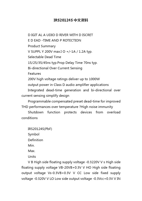
IRS20124S中文资料D IGIT AL A UDIO D RIVER WITH D ISCRETE D EAD -TIME AND P ROTECTIONProduct SummaryV SUPPL Y 200V max.I O +/-1A / 1.2A typ.Selectable Dead Time15/25/35/45ns typ.Prop Delay Time 70ns typ.Bi-directional Over Current SensingFeatures200V high voltage ratings deliver up to 1000Woutput power in Class D audio amplifier applicationsIntegrated dead-time generation and bi-directional over current sensing simplify designProgrammable compensated preset dead-time for improved THD performances over temperature ?High noise immunity Shutdown function protects devices from overload conditionsIRS20124S(PbF)SymbolDefinitionMin.Max.UnitsV B High side floating supply voltage -0.3220V V s High side floating supply voltage VB-20VB+0.3V V HO High side floating output voltage Vs-0.3VB+0.3V V CC Low side fixed supply voltage -0.320V V LO Low side output voltage -0.3Vcc+0.3V V INInput voltage-0.3Vcc+0.3V V OC OC pin input voltage-0.3Vcc+0.3V V OCSET1 OCSET1 pin input voltage -0.3Vcc+0.3V V OCSET2OCSET2 pin input voltage-0.3Vcc+0.3V dVs/dt Allowable Vs voltage slew rate-50V/ns Pd Maximum power dissipation- 1.25W Rth JA Thermal resistance, Junction to ambient -100°C/W T J Junctio n Temperature -150°C T S Storage Temperature-55150°CT LLead temperature (Soldering, 10 seconds)-300°CAbsolute Maximum RatingsAbsolute maximum ratings indicate sustained limits beyond which damage to the device may occur. All voltage parameters are absolute voltages referenced to COM. All currents are defined positive into any lead. The thermal resistance and power dissipation ratings are measured under board mounted and still air conditions.DescriptionThe IRS20124S is a high voltage, high speed power MOSFET driver with internal dead-time and shutdown functions specially designed for Class D audio amplifier applications.The internal dead time generation block provides accurate gate switch timing and enables tight dead-time settings for better THD performances.In order to maximize other audio performance characteristics,all switching times are designed for immunity from external disturbances such as VCC perturbation and incoming switching noise on the DT pin. Logic inputs are compatible with LSTTL output or standard CMOS down to 3.0V without speed degradation. The output drivers feature high current buffers capable of sourcing 1.0A and sinking 1.2A. Internal delays are optimized to achieve minimal dead-time variations. Proprietary HVIC and latch immune CMOS technologies guarantee operation down to Vs= –4V, providing outstanding capabilities of latch and surge immunities with rugged monolithic construction.Recommended Operating ConditionsFor Proper operation, the device should be used within the recommended conditions. The Vs and COM offset ratings are tested with all supplies biased at 15V differential.Symbol Definition Min.Max.Units V B High side floating supply absolute voltage Vs+10Vs+18V V S High side floating supply offset voltage Note 1200VV V HO High side floating output voltage Vs VB V CC Low side fixed supply voltage1018V V LO Low side output voltage0VCC V V IN Logic input voltage0VCC V V OC OC pin input voltage0VCC V V OCSET1OCSET1 pin input voltage0VCC V V OCSET2OCSET2 pin input voltage0VCC V T A Ambient Temperature-40125°CDynamic Electrical CharacteristicsV BIAS (V CC, V BS) = 15V, C L = 1nF and T A = 25°C unless otherwise specified. Figure 2 shows the timing definitions.IRS20124S(PbF)Lead DefinitionsSymbol DescriptionVCC Low side logic Supply voltage VB High side floating supply HO High side outputVS High side floating supply returnINLogic input for high and low side gate driver outputs (HO and LO), in phase with HODT/SD Input for programmable dead-time, referenced to COM. Shutdown LO and HO when tied to COM COM Low side supply returnLO Low side outputOC Over current output (negative logic)OC SET1Input for setting negative over current threshold OC SET2Input for setting positive over current thresholdIRS20124S(PbF)VBHOVSO O C S E T O C S E T VccLOCOM50%50%t off(L)t on(L)90%10%90%10%DT HO-LOt off(H)INHOLOt on(H)DT LO-HO DT/SDHO LOV SDT SD90%Figure 1. Switching Time Waveform Definitions Figure 2. Shutdown Waveform Definitions IRS20124S(PbF)toc filt HIGHVSOCV soct COMCOMtwocVSOCV Soc+tdocCOM COMLOV Soc-15V Vsoc+Vsoc-OCVsoc+Vsoc-COM VSOCFigure 5. OC Waveform DefinitionsFigure 3. OC Input FilterTime Definitions IRS20124S(PbF)IRS20124S(PbF)2.0()2()IRS20124S(PbF)2430()()IRS20124S(PbF)10()10()IRS20124S(PbF)。
psl204电动执行器说明书
PSL执行结构包括PSL201、PSL202、PSL204、PSL208、PSL210、PSL312、PSL314、PSL316、PSL320和PSL325,是由德国PS Automation GmbH执行机构生产商推出的PSL直行程电动执行器。
它具有体积小、重量轻、功能强、智能控制器内装、操作方便、最大行程达到100mm,最大推力可达25KN等特点,可广泛适用于直线动作的阀门开关和调节控制。
PSL执行器结构特点1、PSL直行程电动执行机构行程可调,便于与阀门连接。
2、全部电器元件均采用世界名牌产品,质量可靠,使用寿命长。
3、PSL系列执行器的的电器部件布线严谨并与传动部件完全隔离,提高了执行机构运行性的可靠4、PSL系列执行机构采用柔性盘簧与阀门连接,可避免阀杆与输出轴不同轴给阀门带来的影响,可预置阀门关断力保证阀门的可靠关断,防止泄漏。
5、结构简单、体积小巧、重量轻,便于安装维护;机械零件全部采用CNC加工制作,工艺精湛。
6、PSL电动执行机构为一体化结构设计,位置变送器和伺服放大器做为两个独立部件均可直接装入执行机构内部,直接接受4-20mA控制信号,输出4-20mA或1-5VDC阀位反馈信号,具有自诊断功能,使用和调校十分方便。
7、功能模块式结构设计,通过不同选件的组合,实现从简单到复杂的控制,满足不同应用要求8、传动全部采用小齿隙密封齿轮,具有效率高、噪声低、寿命长、稳定可靠、无需再加油。
9、具有多种运行速度,可满足各种控制系统的要求,以保证系统的快速响应及稳定性。
10、PSL执行器上的驱动电机采用高性能稀土磁性材料制作的高速同步电机,运行平稳。
具有体积小、力矩大、抗堵转、控制精度高等优点。
11、可设置分段调节,即由一台PID调节器输出的双时间比例信号控制两台执行机构(4-12mA 对应PSL1的全开\\全闭,12-20mA对应PSL2的全开\\全闭)。
13、阀位反馈元件采用全密封高精度多圈电位器,具有体积小、精度高、死区小、使用寿命长等特点。
- 1、下载文档前请自行甄别文档内容的完整性,平台不提供额外的编辑、内容补充、找答案等附加服务。
- 2、"仅部分预览"的文档,不可在线预览部分如存在完整性等问题,可反馈申请退款(可完整预览的文档不适用该条件!)。
- 3、如文档侵犯您的权益,请联系客服反馈,我们会尽快为您处理(人工客服工作时间:9:00-18:30)。
RECTRON
Ratings at 25 o C ambient temperature unless otherwise specified. Single phase, half wave, 60 Hz, resistive or inductive load. For capacitive load, derate current by 20%.
元器件交易网RECTຫໍສະໝຸດ ONSEMICONDUCTOR
TECHNICAL SPECIFICATION
RS201L THRU RS207L
SINGLE-PHASE SILICON BRIDGE RECTIFIER
VOLTAGE RANGE 50 to 1000 Volts CURRENT 2.0 Ampere
FIG. 2 - TYPICAL FORWARD CURRENT DERATING CURVE 2.0
AVERAGE FORWARD CURRENT, (A)
60
50
8.3ms Single Half Sine-Wave (JEDED Method)
1.5
40
30
1.0
20
.5
10 0 0 2 4 6 10 20 40 60 NUMBER OF CYCLES AT 60Hz 100
0.1
TJ = 25 Pulse Width = 300us 1% Duty Cycle
.01 .4
.5 .6 .7 .8 .9 1.0 1.1 1.2 INSTANTANEOUS FORWARD VOLTAGE, (V)
PERCENT OF RATED PEAK REVERSE VOLTAGE, (%)
FEATURES
* * * * Ideal for printed circuit board Surge overload rating: 50 amperes peak Mounting position: Any Weight: 2.74 grams
MECHANICAL DATA
* UL listed the recognized component directory, file #E94233 * Epoxy: Device has UL flammability classification 94V-O
.125 (3.2)
.160 (4.1) .140 (3.6) .260 (6.6) .240 (6.1)
Dimensions in inches and (millimeters)
MAXIMUM RATINGS (At T A = 25 oC unless otherwise noted) RATINGS Maximum Recurrent Peak Reverse Voltage Maximum RMS Bridge Input Voltage Maximum DC Blocking Voltage Maximum Average Forward Output Current T A = 50oC Peak Forward Surge Current 8.3 ms single half sine-wave superimposed on rated load (JEDEC method) Operating Temperature Range Storage Temperature Range Typical Junction Capacitance (Note) SYMBOL VRRM VRMS VDC IO I FSM TJ TSTG CJ RS201L 50 35 50 RS202L 100 70 100 RS203L RS204L RS205L 200 140 200 400 280 400 2.0 60 -55 to + 125 -55 to + 150 15 600 420 600 RS206L 800 560 800 RS207L 1000 700 1000 UNITS Volts Volts Volts Amps Amps
o
SYMBOL VF IR
RS201L
RS202L
RS203L RS204L RS205L 1.1 10 0.5
RS206L
RS207L
UNITS Volts uAmps mAmps 2001-5
NOTES : Measured at 1 MHZ and applied reverse voltage of 4.0 volts
INSTANTANEOUS REVERSE CURRENT, (uA) INSTANTANEOUS FORWARD CURRENT, (A)
FIG. 4 - TYPICAL REVERSE CHARACTERISTICS 10 6 4 2 1.0 .6
TJ = 25
10
1.0
.2 .1 .06 .02 .01 0 20 40 60 80 100 120 140
Single Phase Half Wave 60Hz Inductive or Resistive Load
0 20 40 60 80 100 120 140 AMBIENT TEMPERATURE, ( )
FIG. 3 - TYPICAL INSTANTANEOUS FORWARD CHARACTERISTICS
元器件交易网
RATING AND CHARACTERISTIC CURVES ( RS201L THRU RS207L )
FIG. 1 - MAXIMUM NON-REPETITIVE FORWARD
SURGE CURRENT
PEAK FORWARD SURGE CURRENT, (A)
.710 (18.0) .670 (17.0)
RS-2L
.566 (14.4) .528 (13.4)
AC
.528 (13.4) .488 (12.4)
.035 (0.9) DIA. .028 (0.7) TYP.
.787 (20.0)
MAXIMUM RATINGS AND ELECTRICAL CHARACTERISTICS
0 0
C C
pF
ELECTRICAL CHARACTERISTICS (At TA = 25oC unless otherwise noted) CHARACTERISTICS Maximum Forward Voltage Drop per Bridgeat Element at 2.0A DC Maximum Reverse Current at Rated Dc Blocking Voltage per element @T A = 25 C @T A = 100 oC
