LH1518AABTR中文资料
C1815中文资料参数

C1815中文资料参数-2SC1815引脚图-三极管C1815管脚排列-代换本译文译自FAIRCHILE 公司 东芝 飞利浦的1815特性与之基本相同1TO-921发射极 2.集电极 3.基极C1815三极管排列引脚图命名:2SC1815如果叫法省略通常的叫法 C1815 18152SC1815代换型号:2SC945管脚排列一是样的主要参数:Un电参数:放大倍数表示: M 最0.1 0.1 700.21.03.0 3.0后缀符号 O Y GR L 放大倍数70-140120-240200-400350-700C1815特性曲线:V CE M- COLLECTOR -EMITTER VOLTAGE静态特性曲线in山 YYnoTE「一\/归[V], BASE-EMITTER VOLTAGE传输特性曲线0.0020.40.60.81.D10J-J10.1l c [mA], COLLECTOR CURRENT1 10 100 1000o4—N -v o lN UJ M H n o a c J 也直流电流增益曲线l c[mA], COLLECTOR CURRENTl c [mA], COLLECTOR CURRENT山c)<n o A N O _L <cr n l v s M £毛S S A ・(-3器>基极-发射饱和电压曲线集电极-射极饱和电压曲线lc[mA]f COLLECTOR CURRENT100冃MHzI E 二 01 10 100 1000V CB [VL COLLECTOR-BAS E VOLTAG E 输出电容曲线00 10-1 0.londoijdH 」Q Md N V B —N _<e -L N W ni:H n oTr H s s 电流增益带宽曲线lc[mA]f COLLECTOR CURRENT0 46 10 10 1 27TYP [1.27 ±J 20] 4.50 1QJ 5TO-921.27TYP [1.27 ±3.2313 W(K3E +C.-C-3上E。
宗申船外机9.9HP15HP18HP中文说明书

-6-
打开油箱安全阀门时,有易燃蒸汽喷出。请勿吸烟、 吸气或使用明火靠近。
如果机器出现故障,再次使用前应该对它进行全面检 查。如有必要,须请宗申塞尔瓦水上动力专业技术人 员检查。 假如该故障对行驶的安全性方面会造成危害,请勿使 用该机器。
请保持船只和甲板上设备良好的工作状态。 请预备充足的备用零件。 航行前请告知他人您的出行路线。 防止火灾或爆炸。
舷外机应合理使用“油脂图表”中所列的燃油和润 滑油。经常核查燃油和润滑油刻度线。
在每一项保养维护或清洁程序前请先停止机器运行, 遇到复杂的维护情况时,请先取下火花塞帽。
见 图2
请待机器冷却后打开顶罩。机器运行中切勿打开顶
罩。
见 图3
-5-
螺旋桨的注意事项
螺旋桨是舷外机上最危险的部件,因此当机器运行的 时候禁止靠近螺旋桨。为了避免与螺旋桨接触,必 须留给游泳者、滑水者或其它船只使用者足够的空间。
过 热 保 护 系 统 … … … … … … … … … … … … … … … … … … …1 8 紧 急 启 动 程 序 … … … … … … … … … … … … … … … … … … …1 9 磨 合 程 序 … … … … … … … … … … … … … … … … … … … … …1 9 熄 火 程 序 … … … … … … … … … … … … … … … … … … … … …2 0 紧 急 熄 火 程 序 … … … … … … … … … … … … … … … … … … …2 0 正 常 情 况 下 熄 火 … … … … … … … … … … … … … … … … … …2 0 长 期 储 存 时 熄 火 … … … … … … … … … … … … … … … … … …2 0 从 船 上 取 下 舷 外 机 … … … … … … … … … … … … … … … … …2 0 外 部 清 洁 … … … … … … … … … … … … … … … … … … … … …2 1 清 洁 冷 却 水 道 … … … … … … … … … … … … … … … … … … …2 1 清 洁 燃 油 过 滤 网 … … … … … … … … … … … … … … … … … …2 1 维 护 保 养 … … … … … … … … … … … … … … … … … … … … …2 2 定 期 检 查 与 维 护 图 表 … … … … … … … … … … … … … … … …2 2 润 滑 油 图 表 … … … … … … … … … … … … … … … … … … … …2 3 润 滑 油 及 添 加 … … … … … … … … … … … … … … … … … … …2 3 齿 轮 箱 机 油 的 更 换 … … … … … … … … … … … … … … … … …2 3 火 花 塞 … … … … … … … … … … … … … … … … … … … … … …2 4 牺 牲 阳 极 … … … … … … … … … … … … … … … … … … … … …2 4 螺 旋 桨 的 更 换 … … … … … … … … … … … … … … … … … … …2 5 牵 引 … … … … … … … … … … … … … … … … … … … … … … …2 5 存 储 … … … … … … … … … … … … … … … … … … … … … … …2 5 故 障 维 修 … … … … … … … … … … … … … … … … … … … … …2 6 故 障 维 修 表 … … … … … … … … … … … … … … … … … … … …2 7 图 解 … … … … … … … … … … … … … … … … … … … … … … …2 8 宗 申 塞 尔 瓦 舷 外 机 维 修 记 录 … … … … … … … … … … … … …3 6
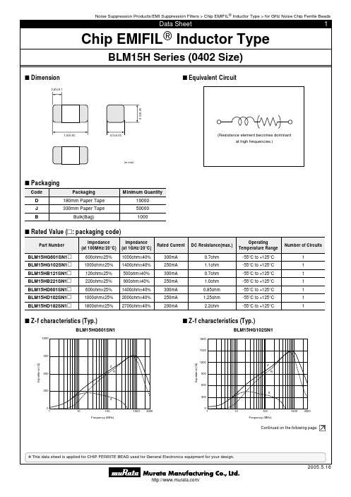
BLM15HD182SN1D中文资料
intended for use in applications other than those specified in this data sheet.
q Aircraft equipment
w Aerospace equipment
e Undersea equipment
r Power plant equipment
mounting and handling) in them to prevent smoking and/or burning, etc.
5. You are able to read a detailed specification in the website of Search Engine (http://search.murata.co.jp/) or catalog library (/catalog/)
I Packaging
Code
Packaging
D
180mm Paper Tape
J
330mm Paper Tape
B
Bulk(Bag)
Minimum Quantity 10000 50000 1000
I Rated Value (p: packaging code)
Part Number
BLM15HG601SN1p BLM15HG102SN1p BLM15HB121SN1p BLM15HB221SN1p BLM15HD601SN1p BLM15HD102SN1p BLM15HD182SN1p
o Data-processing equipment
!0 Application of similar complexity and/or reliability requirements to the applications listed in the above
村辉电感徝LQG15HN33N型号说明书
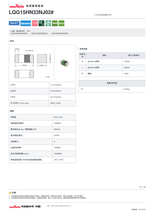
L 尺⼨ 1.0 ±0.05mm W 尺⼨0.5 ±0.05mm T 尺⼨
0.5 ±0.05mm 尺⼨代号 in inch (mm)
0402 (1005)
规格电感徝33nH ±5% 电感徝测试频率
100MHz 额定电流(Itemp) *根据温度上升300mA 直流电阻(最⼤)0.67Ω Q 徝(最⼩)8 Q 徝测试频率
100MHz ⾃⼰共振周波数 (以上)
1500MHz 使⽤温度范围 (不包含⾃⾝温度的提⾼)
-55〜125℃
参考信息包装代号规格最⼩订购单位D φ180mm 纸带10000J φ330mm 纸带50000B
散装
1000
质量(参考值)
1个
0.001g
<品名(附包装代号)⼀览>
LQG15HN33NJ02D 、 LQG15HN33NJ02J 、 LQG15HN33NJ02B
形状
LQG15HN33NJ02#
“#”处为包装规格代号。
在1 / 2
⻚
1. 本⽬录是从株式会社村⽥制作所⽹站中下载的。
规格若有变更,或若其中产品停产,请在订购时确认,恕不另⾏通知。
特性数据图表(同特性的产品可能⽤不同的品名表⽰。
)
电感徝-频率特性(标准值)Q值-频率特性(标准值)
在2 / 2⻚
1. 本⽬录是从株式会社村⽥制作所⽹站中下载的。
规格若有变更,或若其中产品停产,请在订购时确认,恕不另⾏通知。
C1815中文资料参数
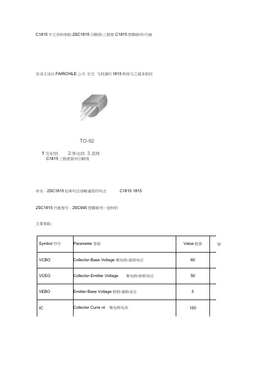
C1815中文资料参数-2SC1815引脚图-三极管C1815管脚排列-代换本译文译自FAIRCHILE 公司 东芝 飞利浦的1815特性与之基本相同C1815三极管排列引脚图命名:2SC1815如果叫法省略通常的叫法 C1815 18152SC1815代换型号:2SC945管脚排列一是样的Symbol符号 Parameter 参数 Value 数值VCBO Collector-Base Voltage 集电极-基极电压 60VCEO Collector-Emitter Voltage 集电极-射极电压 50VEBO Emitter-Base Voltage 射极-基极电压 5IC Collector Curre nt 集电极电流 150主要参数:U1发射极 TO-922.集电极3.基糅C1815特性曲线:V CE[V]. COLLECTOR-EMITTER VOLTAGE静态特性曲线V e 4Vl ? BASE-EMITTER VOLTAGE传输特性曲线J-J1Q.1 0.00.6 0 8IO1 2101 10 100o4—N -v o lN UJ M H n o a c J 也woo直流电流增益曲线基极-发射饱和电压曲线 集电极-射极饱和电压曲线[c [mAl. COLLECTOR CURRENT山0<n o > N O _L <cr r u 吒 -f J100f=1MHzI E二01 10 100 1000V CB FVI COLLECTOR-BASEVOLTAGE输出电容曲线00100.-1电流增益带宽曲线0 46 10 10J---------- 「■'/,,.\ 1M p I\ (R2.29)o 百g --—14-58 U JBTO-921 27TYP [1.27 ±J 20] 1.27TYP[1.27±£].231(K3E+C.-C-3上E。
产品说明书_CN_多功能频有源专业扬声器系统_全U-Meline S15-2018
CN产品说明书S15多功能频有源专业扬声器系统全U M -M e l i n e S 15-20180403 v e r A感谢您购买 产品!请仔细阅读本手册,它将帮助你妥善设置并运行您的系统,使其发挥卓越的性能。
并保留这些说明以供日后参照。
警告:为了降低火灾与电击的风险,请不要将产品暴露在雨中或潮湿环境中。
警告:为了降低电击的风险,非专业人士请勿擅自拆卸该系统。
仅供专业人士操作。
等边三角形中的闪电标记,用以警示用户该部件为非绝缘体,系统内部存在着电压危险,电压。
可能足以引起触电。
可能足以引起触电如系统标有带惊叹号的等边三角形,则是为提示用户严格遵守本用户指南中的操作与维护规定。
注意:请勿对系统或附件作擅自的改装。
未经授权擅自改装将造成安全隐患。
警告:燃不得将明火源(如点的蜡烛)放在器材上面。
1. 请先阅读本说明。
2. 保留这些说明以供日后参照。
3. 注意所有警告信息。
4. 遵守各项操作指示。
5. 不要在雨水中或潮湿环境中使用本产品。
6. 不要将产品靠近热源安装,例如暖气管、加热器、火炉或其它能产生热量的装置(包括功放机 )。
7. 不要破坏极性或接地插头的安全性设置。
如果提供的插头不能插入插座,则应当请专业人员更换插座。
8. 保护好电源线和信号线,不要在上面踩踏或拧在一起(尤其是插头插座及穿出机体以外的部分 )。
9. 使用厂商规定及符合当地安全标准的附件。
10.雷电或长时间不使用时请断电以防止损坏产品。
12. 不要让物体或液体落入产品内——它们可能引起火灾或触电。
13. 请注意产品外罩上的相关安全标志。
. 仅与厂商指定或与电器一同售出的推车、架子、三脚架、支架或桌子一起使用。
推动小车/电器时,应谨防翻倒。
11注意事项产品的安装调试须由专业人士操作。
在使用非本厂规定的吊装件时,要保证结构的强度并符合当地的安全规范。
警告:1扬声器及扬声器系统的产品有限保修期为自正式购买日起的3年。
由于用户不合理的应用而导致音圈烧毁或纸盆损坏等故障,不包含于产品保修项目。
C1815中文资料参数

C1815中文资料参数—2Sc1815引脚图—三极管c1815管脚排列—代换
本译文译自FAIRCHILE公司东芝飞利浦的1815特性与之基本相同
C1815三极管排列引脚图
命名:2SC1815如果叫法省略通常的叫法C1815 1815
2SC1815代换型号:2SC945 管脚排列一是样的
主要参数:
Symbol符号Parameter 参数Value数值Un VCBO Collector—Base Voltage 集电极—基极电压60
VCEO Collector—Emitter Voltage 集电极—射极电压50
VEBO Emitter—Base Voltage 射极-基极电压 5
IC Collector Current 集电极电流150
电参数:
放大倍数表示:
后缀符号O Y GR L
放大倍数70—140120—240200-400350—700 C1815特性曲线:
静态特性曲线
传输特性曲线
直流电流增益曲线
基极-发射饱和电压曲线集电极—射极饱和电压曲线
输出电容曲线
电流增益带宽曲线
外形封装图。
CB RoHS LH15系列电源说明书

15W, AC-DC converterFEATURES● Wide input voltage range: 85 - 264V AC/100 - 370VDC ● Regulated output, Low ripple & noise ● High efficiency up to 84%● Output short circuit, over-current, over-voltage protection ● Plastic case, meets UL94V-0● IEC60950, UL60950, EN60950 approval ● Mounting: Chassis mountingCBRoHSLH15 series features universal input voltage, taking both DC and AC input voltage, low power consumption, high efficiency, high reliability, safer isolation. It offers good EMC performance, which meet IEC/EN61000-4, CISPR22/EN55022, UL60950 and EN60950 standards, and it’s widely used in industrial, office and civil applications.Selection GuideRS Stock No. Part No.* Output PowerNominal Output V oltage and CurrentEfficiency (230V AC, %/Typ.)Max. Capacitive Load(µF)1446265 LH15-10B05A2 14W5V/2800mA 76 20000 1446266 LH15-10B12A2 15W 12V/1250mA 80 5200 1446267 LH15-10B15A2 15V/1000mA 80 5000 1446268 LH15-10B24A224V/625mA84900Input SpecificationsItemOperating Conditions Min. Typ. Max. Unit Input V oltage Range AC input 85 -- 264 V AC DC input 100 -- 370 VDC Input frequency 47 -- 63 HzInput current 115V AC -- -- 0.37 A 230V AC -- -- 0.22 Inrush current 115V AC -- 10 -- 230V AC--20--Leakage current0.3mA RMS typ./230V AC/50HzBuilt in input fuse2A/250V , slow blow.Output SpecificationsItemOperating Conditions Min. Typ. Max. UnitOutput V oltage Accuracy Main circuit -- ±2 -- %Line Regulation Full load -- ±0.5 -- Load Regulation 10% - 100% load-- ±1 -- Ripple & Noise* Main circuit 20MHz bandwidth (peak-peak value) -- 50 100 mV Temperature Coefficient Main circuit --±0.02--%/°CShort Circuit Protection Continuous, self-recovery Over-current Protection≥110%Io self-recoveryOver-voltage Protection5VDC Output≤7.5VDC 12 /15VDC Output ≤20VDC 24VDC Output≤30VDCMin. Load Single output 0 -- -- % Hold-up Time115V AC input -- 15 -- ms230V AC input--80--General SpecificationsItem Operating Conditions Min. Typ. Max. UnitIsolation V oltage Input-outputTest time: 1min3000 -- --V AC Input- 2000 -- --Operating Temperature -40 -- +70°C Storage Temperature -40 -- +105Storage Humidity -- -- 95 %RHSoldering Temperature Wave-soldering 260 ± 5℃; time: 5 - 10s Manual-welding 360 ± 10℃; time: 3 - 5sSwitching Frequency -- 65 -- kHzPower Derating -40℃to -10℃ 2.0 -- --%/°C +55℃to +70℃ 4.0 -- --Safety Standard IEC60950/EN60950/UL60950 Safety Certification IEC60950/EN60950/UL60950Safety Class CLASS IIMTBF MIL-HDBK-217F@25°C > 300,000 hPhysical SpecificationsCasing Material Black flame-retardant and heat-resistant plastic (UL94V-0)Dimension 96.10*54.00*31.00mmWeight 135gCooling method Free air convectionEMC SpecificationsEMI CE CISPR22/EN55022 CLASS B RE CISPR22/EN55022 CLASS BEMS ESD IEC/EN61000-4-2 Contact ±6KV/Air ±8KV Perf. Criteria B RS IEC/EN61000-4-3 10V/m perf. Criteria AEFTIEC/EN61000-4-4 ±2KV perf. Criteria BIEC/EN61000-4-4 ±4KV (See Fig. 5 for recommended circuit) perf. Criteria B SurgeIEC/EN61000-4-5 line to line ±1KV/line to ground ±2KV perf. Criteria BIEC/EN61000-4-5 line to line ±2KV/line to ground ±4KV(See Fig. 5 for recommended circuit)perf. Criteria B CS IEC/EN61000-4-6 10 Vr.m.s perf. Criteria A PFM IEC/EN61000-4-8 10A/m perf. Criteria A V oltage dips, short interruptions and voltagevariations immunityIEC/EN61000-4-11 0%,70% perf. Criteria BProduct Characteristic Curve-40 -10 55 7010080604020T e m p e ra ture De ra ting C urveO u t p u t P o w e r P e r c e n t (%)Inp ut vo lta g e :A m b ie n t t e m p e ra t u re ()℃100 - 370V D C85 - 264VA C100240852642040100608075In p u t V o lt a g eA m b ie n t t e m p e ra t u re :25℃In p u t V o lt a g e D e ra t in g C u rv eO u t p u t P o w e r P e r c e n t a g e (%)VA C 120340100370V D CNote:①When input 85 - 100VAC/240 - 264VAC/100 - 120VDC/340 - 370VDC, it need to be voltage derated on basis of temperature derating; ②This product is suitable for use in natural air cooling environments, if in a closed environment, please contact our company’s FAE.L H15-10B24L H15-10B056065 70 75 80 8590 85115130180230264E f f i c i e n c y (%)Input Voltage(VAC)E fficiency Vs Input Voltage(F ull L oad)L H15-10B24L H15-10B056065 70 75 80 8590 102030405060708090100E f f i c i e n c y (%)Output Power Per centage(%)E fficiency Vs Output L oad(Vin=230VAC)DimensionsNote:1. If the product is not operated within the required load range, the product performance cannot be guaranteed to comply with all parameters in the datasheet;2. Unless otherwise specified, parameters in this datasheet were measured under the conditions of Ta=25℃, humidity<75% with nominal input voltage and rated output load;3. All index testing methods in this datasheet are based on our Company’s corporate standards;4. We can provide product customization service, please contact our technicians directly for specific information;5. Specifications are subject to change without prior notice.。
C1815中文资料参数

-
-
fT
Current Gain Ban dwidth Product
电流增益带宽
VCE=10V, IC=1mA
80
-
Cob
Output Capacitanee输出电容
VCB=10V, IE=0, f=1MHz
-
NF
Noise Figure噪声系数
VCE=6V, IC= RS=10kQ, f=1Hz
C1815中文资料参数-2SC1815引脚图-三极管C1815管脚排列-代换
本译文译自FAIRCHILE公司 东芝 飞利浦的1815特性与之基本相同
1TO-92
1发射极2.集电极3.基极
C1815三极管排列引脚图
命名:2SC1815如果叫法省略通常的叫法C18151815
2SC1815代换型号:2SC945管脚排列一是样的
-
单
放大倍数表示:
后缀符号
O
Y
GR
放大倍数
70-140
120-240
200-400
350-700
静态特性曲线
J-J
1
Q.1
0.0
0.60 8
IO1 2
10
Ve4Vl?BASE-EMITTER VOLTAGE
传输特性曲线
1
10
100
o
4—
N-volNUJMHnoacJ也匸
woo
直流电流增益曲线
[c[mAl.COLLECTOR CURRENT
150
主要参数:
U
IB
Base Current基极电流
50
mA
PC
Collector Power Dissipation耗散功率
C1815中文资料参数

C1815中文资料参数-2Sc1815引脚图-三极管c1815管脚排列-代换
本译文译自FAIRCHILE公司东芝飞利浦的1815特性与之基本相同
C1815三极管排列引脚图
命名:2SC1815如果叫法省略通常的叫法C1815 1815
2SC1815代换型号:2SC945 管脚排列一是样的
主要参数:
Symbol符号Parameter 参数Value数值Un VCBO Collector-Base Voltage 集电极-基极电压60
VCEO Collector-Emitter Voltage 集电极-射极电压50
VEBO Emitter-Base Voltage 射极-基极电压 5
IC Collector Current 集电极电流150
电参数:
放大倍数表示:
后缀符号O Y GR L 放大倍数70-140120-240200-400350-700
C1815特性曲线:
静态特性曲线
传输特性曲线
直流电流增益曲线
基极-发射饱和电压曲线集电极-射极饱和电压曲线
输出电容曲线
电流增益带宽曲线
外形封装图。
TCI 线圈电磁铁线型 1 型号 132 产品说明书

MANUFACTURE ANYTHING
SHOWN THEREIN WITHOUT A 4608, Terminal Blk. To Ring Lugs
WRITTEN PERMISSION FROM
TCI.
NO
REVISION
2
1/16/19
DATE
A
DSW
BY
TOLERANCES
(EXCEPT AS NOTED)
7.89
Side View
C
C
11L 19.13
10L
1E
1
11.00
B 0.87
A
13.65
Bottom View 4
4.82
3E 4E
1R 2R 3R
1.004.75源自Suggested Customer Entrance
B
Either Side Of Enclosure.
See Note: 5
0.44 Dia Mounting Holes,
Horsepower (HP)
Motor Amps
(A)
Maximum Inductance Weight Amps (A) (uH) (LBS)
Losses (W)
Terminal Hole Size (Inches)
60
77
77
408
63 226
0.313
D
TCI Label.
1.00 15.82
D 15.66
4 Top View
Ground Lug. See IOM Manual, Part# 30895 Table S2/0, Wire Size And Torque.
EBR15H中文资料(adam tech)中文数据手册「EasyDatasheet - 矽搜」

EBQ-04--c
.073 [1.85]
.472 [12.00]
.157 [4.00]
'Y' X No of POLES
.275 [7.00]
'Y'
REPLACE 'Y' WITH PITCH A = .138 [3.50] B = .150 [3.81] E = .276 [7.00] G = .300 [7.62]
EB108 = 0.342“直 EB109 = 0.850“直
中心线 间距
A = .138" [3.50mm] B = .150" [3.81mm] c = .197" [5.00mm] D = .200" [5.08mm] E = .276" [7.00mm] G = .300" [7.62mm] H = .394" [10.00mm] J = .400" [10.16mm] k = .591" [15.00mm] S = .374" [9.50mm]
.100 [2.54] .200 [5.08]
.138 [3.50]
.038 [0.95]
.020 [0.50]
.600 [15.24]
.020 [0.50]
.997 [25.30]
.543 [13.80]
EBv2-02-D
.193 [4.90]
.031 [0.80]
.600 [15.24]
3位置堆放块
电气:
Operating voltage: 250V AC max. Current rating: 7 to 15 Amp max 接触电阻:20mΩ以下.初始 绝缘电阻:5000MΩ分钟. Dielectric withstanding voltage: 1500V AC for 1 minute
变压器必备之常用H系列和Z系列矽钢片标号规格
变压器必备之常用H系列和Z系列矽钢片标号规格变压器必备之常用H系列和Z系列矽钢片标号规格矽钢片的好坏取决于矽钢片的材质和加工工艺,EI型矽钢片的加工工艺最重要。
它直接影响变压器的质量,加工工艺中的冲压方法,退火方法最重要,同一材质的矽钢片冲压毛刺小的与毛刺大的制作的变压器性能差7%,同一材质的矽钢片退后(氮气保护退火)与不退火的矽钢片制作的变压器性能相差7-10%国内常用的H系列编号,是沿用70年代-90年代的日本新日铁的标号。
而现在正规厂家都按照新的标号标示。
旧标号新标号性能相当材料我知道的批发价格{退火片要贵1000-2000米/吨}吨H12 50H270 50WW270 B50A270 21000元H14 50H310 50WW310 B50A310 15800元H18 50H470 50WW470,B50A470 14000元H23 50H600 50WW600,B50A600 12600元H30 50H700 50WW700,B50A700 11000元H40 50H800 50WW800,B50A800 9600元H50 50H1000 50WW1000,B50A1000 8500元H60 50H1300 50WW1300,B50A1300 8000元从工艺上说,Z系列均为冷轧有取向高含硅量,H系列一般是冷轧无取向中高含硅量,H型无取向性钢片也有0.35MM的薄片。
但是产量很少,一般用于要求较高的场合。
无取向硅钢片常用的有下列几种:H50 H23 H18 H14 h12比重7.85 7.75 7.65 7.65 7.65铁损P1.5/50HZ≤13 6.2 4.7 4.0 3.6磁通密度B50≥ 1.69 1.66 1.64 1.61 1.6按温升来说H18低于H23,H23低于H50按空载电流则相反。
另外同一牌号有白片黑片之分,黑片{退火片}性能优于白片。
另外同一牌号铁芯尺寸不同性能也不同。
种子老化试验箱详细参数

种子老化试验箱详细参数
种子质量的高不高人为是判断不出来的,需要通过专业的试验来进行检验,而种子老化则是判断种子活力指数的一种最普遍方法。
在一般实验室中,实验人员会使用种子种子老化试验箱来加速种子的老化。
通过模拟自然环境:湿度、光照、温度等参数,让种子在老化试验箱中生长、死亡。
目前,种子老化试验箱广泛应用于各科学院校,种子培养基地,实验室等场合,是种子品质检测所不可缺的仪器。
种子老化试验箱能利用高温高湿老化得到同一品种不用老化程度的样品,而如果只通过自然老化的途径是非常困难的,这种人工加速老化的方式可以说是非常理想的手段。
以林木种子为例,在35℃及75%的相对湿度下进行老化,而一般需要几个月时间;而在40℃及100%相对湿度下进行老化,只要几天时间。
所以在老化试验前,我们需要根据品种来选择合适的种子老化试验箱,因为仪器的控温控湿范围都有不同,一般的仪器控温范围在5-65℃;最大湿度能控制在95%。
托普云农种子老化试验箱具有三种型号,每种型号的产品参数都不同,就比如容积,LH-80型号种子老化试验箱容积是80L,而LH-150型/LH-150S型容积则是150L,除了这点不同之外还有在温度以及湿度控制方面控制范围都不同,所以用户在选择时要根据自己的需求谨慎选择。
以下是种子老化试验的功能特性:
1、微电脑液晶智能化温控显示,PID自整定,自动示温示警,漏电保护,时间设置,控温精确可靠。
2、双重门结构,内门采用钢化玻璃门,观察箱内情况时不影响温度。
3、不锈钢工作室,精密加热方式,温度均匀,且断电后,仍能保持较长时间的恒温。
4、LH150S型采用精确控温及平衡加湿。
5、整机配置中含老化盒。
CITIZEN CLL042-1818A5-50KL1A1 LED包装数据表说明书

and are trademarks or registered trademarks of CITIZEN HOLDINGS CO., LTD. JAPAN.is a trademark or a registered trademark of CITIZEN ELECTRONICS CO., LTD. JAPAN.(1) Absolute Maximum Rating*1 Input power and forward current are the values when the LED is used within the range of the derating curve in this data sheet.*2 Refer to 3. Outline drawing for Tc measurement point *3 D.C. Current : Tj = Tc + Rj-c X PiRating Value Junction Temperature Storage TemperatureT st -40 ~ +100Operating TemperatureT op -30 ~ +85Tj 140Case Temperature Tc100Reverse Current I R 190Forward Current I F Input Power Pi 144.92160Mnimum currentI F min Parameter Symbol AnodeCathodeMarking 2Marking 1(Tc Measurement Point)Resin area (including white resin)Y7. Packing Specifications (1) PackingAn empty tray is placed on top of a 6-tier tray which contains 30 products par tray.They are placed between buffers and banded crisscross with tape.(Smallest packing unit: 180 pieces)Above banded trays are sealed in a aluminum bag, and a label stating name, quantity and Lot No. of the product is put on the aluminum bag.Tray (Dimensions: 310 x 210 x 12 mm / Materials: Electrically conductive PS)< Example of indication label >1. TYPE e.g. CLL042-1818A5-50KL1A12. P.No. (Cutomer's P/N)3. Lot No.- First and second letter: Last digit of the year e.g. 13 : year 2013 - Third letter: Production month e.g. 3 : MarNote: October, November and December are designated - Forth letter: CE's control number e.g. 50354. QuantityCITIZEN ELECTRONICS CO.,LTD. JAPANSymbolCITILEDNameCLL042-1818A5-50KL1A1CUSTOMERPASSCITIZEN ELECTRONICSTYPE P. NO Lot No Q'ty : ******-******-*******: ******: *******: ***---(1)---(2)---(3)---(4)< Packing figure >。
lha801u物理参数
lha801u物理参数
【最新版】
目录
1.引言
2.LHA801U 的物理参数概述
3.LHA801U 的主要物理参数详解
3.1 尺寸
3.2 重量
3.3 工作温度
3.4 电源
3.5 输出功率
4.结论
正文
【引言】
本文将为您详细介绍 LHA801U 的物理参数,包括尺寸、重量、工作温度、电源以及输出功率等方面的信息,帮助您全面了解这款产品。
【LHA801U 的物理参数概述】
LHA801U 是一款高效、多功能的设备,其物理参数在设计上充分考虑了用户的需求,具有较高的实用性。
【LHA801U 的主要物理参数详解】
【3.1 尺寸】
LHA801U 的尺寸为 XXXmm x XXXmm x XXXmm,便于安装和携带。
【3.2 重量】
LHA801U 的重量为 XXX 千克,轻巧便携。
【3.3 工作温度】
LHA801U 的工作温度范围为-XX°C 至+XX°C,适应各种环境。
【3.4 电源】
LHA801U 的电源为 XXX 伏特,通过 XXX 方式供电,确保设备稳定运行。
【3.5 输出功率】
LHA801U 的输出功率为 XXX 瓦特,满足用户对于设备的性能需求。
【结论】
综上所述,LHA801U 在尺寸、重量、工作温度、电源和输出功率等方面的物理参数表现出色,能满足用户的多样化需求。
LH1520
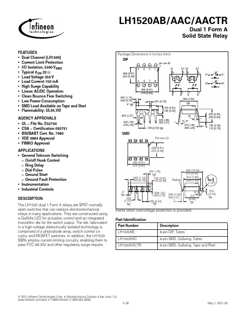
FEATURES•Dual Channel (LH1500)•Current Limit Protection•l/O Isolation, 5300 V RMS•Typical R ON 20 Ω•Load Voltage 350 V•Load Current 150 mA•High Surge Capability•Linear, AC/DC Operation•Clean Bounce Free Switching•Low Power Consumption•SMD Lead Available on Tape and Reel •Flammability; UL94,VØAGENCY APPROVALS•UL – File No. E52744•CSA – Certification 093751•BSI/BABT Cert. No. 7980•VDE 0884 Approval•FIMKO ApprovalAPPLICATIONS•General Telecom Switching– On/off Hook Control– Ring Delay– Dial Pulse– Ground Start– Ground Fault Protection•Instrumentation•Industrial ControlsDESCRIPTIONrelays in many applications. They are constructed usinga GaAIAs LED for actuation control and an integrated monolithic die for the switch output. The die, fabricated in a high-voltage dielectrically isolated technology is comprised of a photodiode array, switch control cir-cuitry, and MOSFET switches. In addition, the LH1520 SSRs employ current-limiting circuitry, enabling them to pass FCC 68.302 and other regulatory surge require-Part IdentificationPart Number DescriptionLH1520AB8-pin DIP, TubesLH1520AAC8-pin SMD, Gullwing, TubesLH1520AACTR8-pin SMD, Gullwing, Tape and Reel2001 Infineon Technologies Corp. • Optoelectronics Division • San Jose, CA www.infi/opto • 1-888-Infineon (1-888-463-4636)Absolute Maximum Ratings, T A =25 °CStresses in excess of the absolute Maximum Ratings can cause permanent damage to the device. These are absolute stress ratings only. Functional oper-ation of the device is not implied at these or any other conditions in excess of those given in the operational sections of this document. Exposure to absolute Maximum Ratings for extended periods of time can adversely affect reliability.Ambient Temperature Range (T A )....................................–40 to +85 °C Storage Temperature Range (T stg ).................................–40 to +150 °C Pin Soldering Temperature (t=10 s max) (T S ).............................260 °C Input/Output Isolation Voltage(t=1.0 s, I ISO =10 µA max) (V ISO )....................................... 5300 V RMS Pole-to-Pole Isolation Voltage (S1 to S2)*(dry air, dust free, at sea level).................................................1600 V LED Continuous Forward Current (I F ).........................................50 mA LED Reverse Voltage (I R ≤10 µA) (V R )...........................................8.0 V DC or Peak AC Load Voltage (I L ≤50 µA) (V L )..............................350 V Continuous DC Load Current (I L )One Pole Operating.................................................................150 mA Two Poles Operating ...............................................................110 mA Peak Load Current (t=100 ms) (single shot) (I P )................................†Output Power Dissipation (continuous) (P DISS )........................600 mW*Breakdown occurs between the output pins external to the package.†Refer to Current Limit Performance Application Note for a discussion on relay operation during transient currents.Recommended Operating ConditionsElectrical Characteristics, T A =25°CMinimum and maximum values are testing requirements. T ypical values are characteristics of the device and are the result of engineering evaluations. T ypical values are for information only and are not part of the testing requirements.Parameter Sym.Min.Typ.Max.UnitsTest ConditionsInputLED Forward Current, Switch Turn-on I Fon — 1.0 2.0mA I L =100 mA, t=10 ms LED Forward Current, Switch Turn-off I Foff 0.2 1.1—mA V L ±300 V LED Forward Voltage V F1.15 1.26 1.45V I F =10 mAOutput ON-resistance R ON 122025 ΩI F =5.0 mA, I L =50 mA OFF-resistance R OFF0.55000—G ΩI F =0 mA, V L =±100 V Current LimitI LMT230270370mA I F =5.0 mA, t=5.0 ms V L ±6.0 VOff-state Leakage Current ——0.02200nA I F =0 mA, V L =±100 V —— 1.0µA I F =0 mA, V L =±350 V Output Capacitance——55—pFI F =0 mA, V L =1.0 V —10—I F =0 mA, V L =50 V Pole-to-Pole Capacitance (S1 to S2)——0.5—pF I F =5.0 mA Switch Offset ——0.15—V I F =5.0 mA TransferInput/Output Capacitance C ISO — 1.1—pF V ISO =1.0 VTurn-on Time t on — 1.4 2.0ms I F =5.0 mA, I L =50 mA Turn-off Timet off—0.72.0ms I F =5.0 mA, I L =50 mATypical Performance Characteristics Figure 1. LED Voltage vs. TemperatureFigure 2. LED Current for Switch Turn-On vs. TemperatureFigure 3. Current Limit vs. TemperatureFigure 4. LED Dropout Voltage vs. TemperatureFigure 6. Variation in ON-Resistance vs. LED CurrentFigure 8. Insertion Loss vs. FrequencyFigure 11. Leakage Current vs. Applied Voltage at ElevatedFigure 14. Switch Offset Voltage vs. LED CurrentFigure 18. Turn-Off Time vs. LED Current。
- 1、下载文档前请自行甄别文档内容的完整性,平台不提供额外的编辑、内容补充、找答案等附加服务。
- 2、"仅部分预览"的文档,不可在线预览部分如存在完整性等问题,可反馈申请退款(可完整预览的文档不适用该条件!)。
- 3、如文档侵犯您的权益,请联系客服反馈,我们会尽快为您处理(人工客服工作时间:9:00-18:30)。
FEATURES
•5300 V RMS I/O Isolation
•Current-limit Protection Built-in
•Linear AC/DC Operation
•High-reliability Monolithic Receptor
•Low Power Consumption
•Clean, Bounce-free Switching
•High Surge Capability
•Surface Mountable
•Flammability; UL94,VØ
AGENCY APPROVALS
•UL – File No. E52744
•CSA – Certification 093751
•BSI/BABT Cert. No. 7980
•VDE 0884 Approval
•FIMKO Approval
APPLICATIONS
•General Telecom Switching
•Instrumentation
•Industrial Controls
DESCRIPTION
high-performance circuits such as current limiting in nor-
mally-open switches. The output die integrates the pho-todiode receptor array, turn-on and turn-off control circuitry, and the MOSFET switches. The optically-cou-pled input is controlled by a highly efficient GaAlAs infra-Part Identification
Part Number Description
LH1518AT 6-pin DIP, Tubes
LH1518AAB 6-pin SMD, Gullwing, Tubes
元器件交易网
2001 Infineon Technologies Corp. • Optoelectronics Division • San Jose, CA
www.infi/opto • 1-888-Infineon (1-888-463-4636)
元器件交易网
Absolute Maximum Ratings, T A=25°C
Stresses in excess of the absolute Maximum Ratings can cause permanent
damage to the device. These are absolute stress ratings only. Functional oper-
ation of the device is not implied at these or any other conditions in excess of those given in the operational sections of this document. Exposure to absolute Maximum Ratings for extended periods of time can adversely affect reliability.
Ambient Temperature Range (T A)....................................–40 to +85°C
Storage Temperature Range (T stg).................................–40 to +150°C
Pin Soldering Temperature (t=10 s max) (T S).............................260°C
Input/Output Isolation Voltage (V ISO) ..................................5300 V RMS
LED Continuous Forward Current (I F).........................................50 mA
LED Reverse Voltage (I R≤10 µA) (V R)...........................................8.0 V
DC or Peak AC Load Voltage (I L≤50 µA) (V L)..............................250 V
Continuous DC Load Current (I L)
Bidirectional Operation............................................................155 mA
Unidirectional Operation..........................................................300 mA
Peak Load Current (t=100 ms) (single shot) (I P).................................†
Output Power Dissipation (P DISS).............................................550 mW
†Refer to Current Limit Performance Application Note 58 for a discussion on relay operation during transient currents.
Electrical Characteristics, T A=25°C
Minimum and maximum values are testing requirements. Typical values are characteristics of the device and are the
result of engineering evaluations. Typical values are for information only and are not part of the testing requirements.
Parameter Sym.Min.Typ.Max.Units Test Conditions
Input
LED Forward Current, Switch Turn-on I Fon—0.8 2.0mA I L=100 mA, t=10 ms
LED Forward Current, Switch Turn-off I Foff0.20.7—mA V L±200 V
LED Forward Voltage V F 1.15 1.26 1.45V I F=10 mA
Output
R ON101520ΩI F=5.0 mA, I L=50 mA ON-resistance
ac/dc: Pin 4 (±) to 6 (±)
dc: Pin 4, 6 (+) to 5 (±) 2.5 3.75 5.0I F=5.0 mA, I L=100 mA OFF-resistance R OFF0.55000—GΩI F=0 mA, V L=±100 V
Figure 1. LED Current for Switch Turn-on vs. Temperature
Figure 2. ON-Resistance vs. Temperature
Figure 5. Switch Capacitance vs. Applied Voltage
元器件交易网
Figure 6. Switch Offset Voltage vs. Temperature
Figure 8. Leakage Current vs. Applied Voltage at Elevated Temperatures
Figure 9. Turn-on Time vs. Temperature Figure 10. Turn-on Time vs. LED Current Figure 11. Turn-Off Time vs. LED Current
元器件交易网。
