SDT200TR中文资料
infinova SS200T3R 嵌入式 VMS 用户手册说明书

Infinova® SS200T3R Embedded VMS BoxEmbedded VMS User ManualContents in the Package1. Embedded VMS device2. Device power chord3. User manual (this document)4. License Agreement document5. Motherboard drivers installation DVD6. Graphics card driver installation CD7. PCI network card driver installation CD8. Rack mount rails and screws9. Data cables for hard disk drives10. Power cable connectors for hard disk drives11. VMS Client Software installation CDSerial NumberEach Embedded VMS has a unique serial number.The serial number is available on the tag attached to the deviceThe serial number can also be viewed from the Graphical User Interface, as follows –1.Click on the ‘Product Information..’ button from the toolbar available at the bottom of theGraphical User Interface.2.This will pop up the ‘Product information’ dialog box, which displays the serial number of thedevice.Serial number of this device is -(If this is a digital copy of the Embedded VMS User Manual, it will not have the serial number mentioned here)Know Your HardwareNote – The images are for reference purpose. Actual hardware may differ a bit, depending on the Embedded VMS model.Front View:Side View:Rear View:Factory DefaultsIP address: 192.168.0.55 Operator user name (to be used for connection from client software): op Operator user password (to be used for connection from client software): opDevice Setup (Hardware)Note – The images are for reference purpose. Actual hardware may differ a bit, depending on the Embedded VMS model.Connect Power Chord:Connect Monitor:The Embedded VMS device provides VGA display output port. Connect a VGA monitor.Connect Network Cable:Connect Keyboard:USB keyboard can be connected to any of the 4 USB ports.PS2 keyboard can be connected to the PS2 keyboard input portNote – Some of the Embedded VMS models do not support PS2 keyboard input port. USB keyboard needs to be used in such cases.Connect Mouse:USB mouse can be connected to any of the 4 USB ports.PS2 mouse can be connected to the PS2 mouse input portNote – Some of the Embedded VMS models do not support PS2 mouse input port. USB mouse needs to be used in such cases.Device Setup (Software)Note – The images are for reference purpose. Actual user interface may differ, depending on the firmware version installed on the Embedded VMS device.1. Click on the ‘Settings’ button from the toolbar available at the bottom of the Graphical UserInterface.Click on the ‘Quick Configuration Wizard..’ menu.2. This will start the ‘Quick configuration wizard’. Follow the wizard and update configurationparameters on each of the wizard pages; to complete the basic set up.3. Click on the ‘Settings’ button from the toolbar available at the bottom of the Graphical UserInterface.Click on the ‘Settings..’ menu.4. This will pop up the settings dialog box.5. Navigate to the ‘Video devices -> Channels’ page from the navigation pane available at the lefthand side.6. Select any of the channels li sted. Click on the ‘Edit’ menu to configure the channel. Channelconfiguration includes selecting the video source / camera and specifying streams to be used 7. Close the settings dialog box, after channels configuration is done.Dual Monitor ConfigurationNote – Dual monitor configuration is not supported by all Embedded VMS models. Please refer to the datasheet to check whether this device supports dual monitor configuration.Connect 2nd Monitor:The Embedded VMS device provides HDMI and DVI display output ports. Connect 2nd monitor to HDMI port or the DVI port.Software Setting:1. Click on the ‘Settings’ button from the toolbar available at the bottom of the Graphical UserInterface.Click on the ‘Use Dual Monitor Mode’ menu.Note – If 2nd mo nitor is not connected, error will be displayed and the device will switch back to ‘Single Monitor Mode’MaintenanceThe Embedded VMS device has built in maintenance modules and watchdog to ensure that the device functions smoothly. All basic maintenance procedures are built-in in the device and no maintenance activity is required during normal operation.Device boot:When powered on, the device initializes and starts processing. Typical boot up time is 30 seconds. Sometimes, especially when the last shut down is not clean, the device may take up to one minute to check consistency of hardware and configuration data. Please be patient and wait for the device to complete the initialization and start the VMS processing. The VMS user interface is launched automatically, when initialization is complete.Rebooting the device (Software):1. Click on the ‘Device Maintainance’ button from the toolbar available at the bottom of theGraphical User Interface.2. Click on the ‘Reboot’ menu.3. Conformation message will be displayed. Please accept it to initiate the device reboot.Note – During software initiated device reboot, all processes are closed cleanly before shutting down. This takes approximately 2 minutes. It is highly recommended to wait for approximately 2 mins for clean shut down and reboot of the device.Shutting down the device (Software):1. Click on the ‘Device Maintainance’ button from the toolbar available at the bottom of theGraphical User Interface.2. Click on the ‘Shut down’ menu.3. Conformation message will be displayed. Please accept it to initiate the device shut down.Note – During software initiated device shut down, all processes are closed cleanly before shutting down. This takes approximately 2 minutes. It is highly recommended to wait for approximately 2 mins for clean shut down.Rebooting the device (Hardware):1. Please press the ‘Power’ button available on the front panel of the device. Release the buttonimmediately after pressing it.2. The device will shut down gracefully.3. Please pr ess the ‘Power’ button again to restart the deviceNote – It is recommended to use software initiated shut down or software initiated reboot, instead of using hardware controlled shut down and reboot.Hard reboot (Hardware):WARNING – Please do not use hard reboot option unless required. Hard reboot option isexpected to be used only in exceptional cases. It is recommended to use softwareinitiated reboot option, which ensures graceful shut down of the device. If softwareinitiated reboot does not work due to exceptional situations, then hardware initiated shutdown can be tried first. If hardware initiated shut down too does not work, hard rebootoption can be tried as a last option.1. Please press the ‘Shutdown’ button available on the front panel of the device.Note – It is recommended to use software initiated shut down or software initiated reboot, instead of using hardware controlled shut down and reboot.Advanced Maintenance:For information on the advanced maintenance procedures, please refer to the ‘Embedded VMS Advanced Maintenance Guide’WARNING – Embedded VMS advanced maintenance is special activity and it is highlyrecommended that only trained engineers operate the maintenance procedures. Incorrectconfiguration during the advanced maintenance may result in the Embedded VMS devicebecoming non-functional.TroubleshootingFirst step during troubleshootingIf any problem is observed or if of the operation dos not work as expected, first troubleshooting step is to reboot the device.Please refer to the ‘Rebooting the device (Software)’ sub-section from ‘Maintenance’ section, available in this document; for steps for rebooting the device.Reset to factory defaults (from Graphical User Interface)1. Click on the ‘Reset’ button from the toolbar available at the bottom of the Graphical UserInterface.2. To reset all the configurations except the IP address, click on the ‘Reset to factory defaults(without IP address reset)’.3. To reset all the configurations including the IP add ress, click on the ‘Reset to factory defaults(with IP address reset)’.Reset to factory defaults (from keyboard)1. Reboot the device, as explained in the ‘Maintenance’ section in this document.2. While the device is rebooting, keep the CTRL and R keyboard keys pressed3. When the device reboots, it shows ‘factory reset’ screen. Select the ‘factory default reset’ modeand click on the ‘Apply’ button.Problem - Device shows the login screenPlease note that when device login screen is visible, the video capture and recording is instopped state. Hence the device should be rebooted immediately, to resolve the issue.In normal operation of the device, the login screen will never be visible.However, as part of ‘Advanced maintenance’ operations, login screen may be displayed sometimes.If login screen is observed, during any of the configurations being done to the device, please reboot the device (as explained in the ‘Maintenance’ section in this document) to make the device functional again. Problem - Device not booting upPlease remove all USB devices, especially USB data devices connected to the device; and reboot the device, as explained in the ‘Maintenance’ section in this document.Problem - Device takes long time to boot up(a) During boot up, device checks hardware and configuration data for consistency and tries to resolve inconsistencies, if any are observed. Hence sometimes when inconsistencies are located, it may take up to one minute to complete the initialization. The monitor display may be blank during the initialization in such cases. Please wait till the initialization finishes and VMS user interface is displayed.(b) Please remove any USB storage devices connected to the Embedded VMS device, for faster boot up. Problem –‘Configuration error’ is displayed instead of video stream for one or more camerasThe device is designed for handling video streams of specific resolutions. To know the details, please click on the ‘Settings -> Video stream configuration’ menu. This will display the video stream configuration restrictions.Please edit the camera video stream resolutions to comply with these restrictions. The ‘Configuration error’ message will go away and live video will be displayed for the camera.Problem –‘Hardware error’ is disp layed instead of video stream for one or more camerasWhen the monitor(s) are connected / disconnected or when the display resolution changes, embedded VMS device may show ‘Hardware error’ instead of video stream for one or more cameras.To resolve this issue, please follow the steps described below -1. Click on the ‘Reset’ button from the toolbar available at the bottom of the Graphical UserInterface.2. Click on the ‘Reset display’ menu.Problem – USB port does not workPlease disconnect the USB device connected to the USB port available in front of the device.Connect all USB devices to the USB ports available on the back side of the device.Problem – Monitor does not show display outputPlease ensure that the monitor is connected to the correct display output ports available on the device, as per the description available in the ‘Device Setup (Hardware)’ section and ‘Connect Monitor’ sub-section from this document.HelpManufacturer Website: Technical Support E-mail Address: ************************。
SD200-50、75伺服驱动器用户手册
SDTGA200灰挥测试仪说明书

高温炉加热、恒温时电源通断情况,以提示操作人员仪器控温是否正常。
3.3.2主界面
如图3-12所示,主界面分为温度显示区、状态显示区、时间显示区、方式显示区。下面对四个区进行详细介绍:
1.温度显示区,如图3-6。箭头前面的数字表示加热起始温度,箭头后面显示
数字表示仪器加热所要到达的恒温点。此恒温点根据试验方
3、按3.1.2要求配备良好的电源;
4、分析天平(感量:0.0001g);
5、国家标准煤样:推荐使用煤炭科学研究院研制的国家级标准煤样;
6、灰分坩埚、灰分坩埚架;
7、挥发分坩埚、挥发分坩埚架;
8、送样铲、样勺。
3.2.2开箱
开箱时务必有湖南三德科技股份有限公司专职人员在场,然后按照发货、装箱清单检查仪器是否完整、有无破损,若有问题请向湖南三德科技股份有限公司专职人员说明。
K=80+(18-25)=73
注意:确定好新的室温校正系数后,按3.3.3所述修改即可。
②按“↑”或“↓”键选择“慢灰”、“快灰1”、“快灰2”或“挥发分”,然后按“开炉/关炉”键加热,待仪器分别恒温在500℃、815℃(850℃)、920℃时,用万用表测量热电偶正负极电压(热电偶参考温度为室温时的热电动势),经换算成参考温度为0℃时的热电动势后,再与K分度表比较、调整热偶系数以达到校准炉温的目的。
图3—2
2.安装好炉门,并使炉门与炉体之间配合良好。
3.打开仪器炉门,检查高温炉内壁的完整性(确定无断裂现象),然后将刚玉板安装到炉膛内(半圆形缺口朝向炉膛)。
注意:安装高温炉炉门及刚玉板时,务必小心!以免碰坏保温材料!
4.安装送样平台,选择快灰1方式进行试验时,将送样平台旋转至炉口处,并使送样平台处于水平状态且紧靠在刚玉板的上方。选择其他方式进行试验,将送样平台旋转至仪器右侧,并使平台处于垂直状态。
RT200剪折机床数控系统用户手册
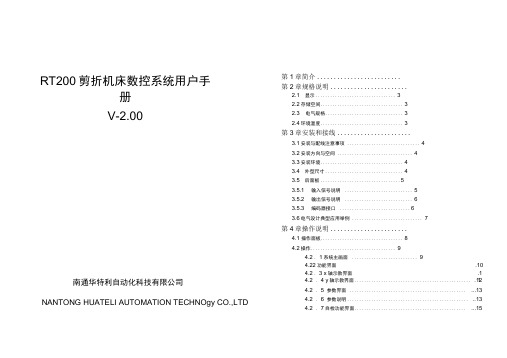
南通华特利自动化科技有限公司NANTONG HUATELI AUTOMATION TECHNOgy CO.,LTD 4.2 . 4 y轴示教界面................................................ .12 4.2 . 5 参数界面................................................ (13)4.2 . 6 参数说明.................................................. ..13 4.2 . 7自检功能界面.............................................. (15)RT200剪折机床数控系统用户手册V-2.00第1章简介.........................第2章规格说明.......................2.1 显示 (3)2.2存储空间 (3)2.3 电气规格 (3)2.4环境温度 (3)第3章安装和接线......................3.1安装与配线注意事项 (4)3.2安装方向与空间 (4)3.3安装环境 (4)3.4 外型尺寸 (4)3.5 后面板 (5)3.5.1 输入信号说明 (5)3.5.2 输出信号说明 (6)3.5.3 编码器接口 (6)3.6电气设计典型应用举例 (7)第4章操作说明.......................4.1 操作面板 (8)4.2操作 (9)4.2 . 1系统主画面 (9)4.22功能界面.104.2 . 3 x轴示教界面.114.2 . 8工步设置界面 ............................................... ...15 4.2 . 8阀组设置界面 .............................................. (15)感谢您使用RT200折弯机数控系统,为了您的正确使用与安全,请先 仔细阅读本手册,并提出您宝贵的意见!折弯机数控系统具有以下专业控制功能:1、 对折弯机的后挡料及油缸中挡块位置进行定位控制。
SDT200TM资料
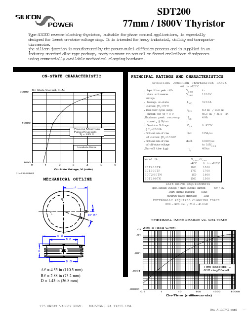
SDT200 / T200
FULL CYCLE AVERAGE POWER
@ Tj = 125 C 60 Hz
FULL CYCLE AVERAGE POWER at TJ = 125oC Full Cycle average IT(AV) (A) 500 600 700 800 900 1000 1200 1400 1600 1800 2000 2500 3000 3200 180o half-sine PT(AV) (W) 423 544 699 798 929 1060 1335 1617 1907 2205 2511 3315 4177 4539 120o square wave PT(AV) (W) 471 599 730 865 1001 1140 1425 1719 2022 2336 2660 3516 4445 4840
Rthj-case(dc) = .012 degC/watt
.00001 0.1 1 10 100 1000 10000
On-Time (milliseconds)
175 GREAT VALLEY PKWY.
MALVERN, PA 19355 USA
Rv A 1/70 pg1 e. 01/1 ae -
ON-STATE CHARACTERISTIC
PRINCIPAL RATINGS AND CHARACTERISTICS
OPERATING JUNCTION TEMPERATURE RANGE -40 to +125oC t o . Rpttv pa of eeiie ek fVD R M sae ad rvre tt n ees VRRM 1800V vlae otg . Aeae o-tt vrg nsae I 3200A T(AV) current @TC =70oC 83m /1. m . s 00 s .Pa hl ccesre ek af yl ug I SM T cret fr V = 0 V urn o r 55.0 kA / 51.0 kA .Maximum peak recovery IM 49A R c r e t @ 2 /ms urn, A . O-tt Vlae nsae otg VT M 0.975V @ IT=2000A .Ciia rt o rs rtcl ae f ie d/t id 125A/us of current @VD =1500V .Ciia rt o rs rtcl ae f ie d/t vd 1000V/us o ofsaevlae f f-tt otg to 0 D R M .8V .unoftm (y) Tr-f ie tp t 400us q Model No. VD R M /VR R M -0oC 4 0 t + 2 oC o 15 1800 1800 1700 1700 10 60 1600 1500 1500
微机调速器技术说明书

SDT200水轮机微机调速器说明书编写:李书明陈军审核:史恒批准:郭效军国电南京自动化股份有限公司一九九九年二月目录1 概述 (1)2 硬件配置 (3)3软件结构 (3)4操作说明 (4)5 机械结构形式 (7)6 电柜原理图和端子布置图 (7)一.概述SDT200水轮机调速器是以可编程控制器(PLC)为调节控制核心的新型水轮机微机调速装置,配以现代控制理论为核心的软件,与水轮机的电液执行机构组成水轮机调速系统。
该种型号的调速器适用于各种不同容量的混流式水轮发电机组和轴流转桨式水轮发电机组的调节控制。
与其它类型调速器相比,具有可靠性高,可维护性好,性能价格比高的优点。
1.规格和主要技术指标型号:SDT200系统结构:微机调节+电液随动系统调节规律:变结构、变参数并联PID控制微机型式:PLC(PLC形式可选GE系列、MODICON系列、三菱系列)测频方式:数字测频,2-100 Hz测频分辨率:0.00125 Hz/1LSB比例增益:Kp= 0-10积分增益:Ki= 0-5微分增益:Kd= 0-10永态转差系数:bp=0-10%人工转速死区:0-10%模数与数模转换分辨率:12 位电柜输出:电压±10 V,电流±0.2 A供电电源:交流 220 V 和直流 220 V 并联供电电液转换器:环喷式、双锥式或其他型式电液伺服阀主接力器反馈:线位移传感器电气反馈转速死区:〈=0.03%接力器不动时间: <=0.2 s2.主要功能2.1 自动调节和控制功能1.以最佳过程起动水轮发电机组,启动过程可使机组频率跟踪电网频率;也可以按给定频率启动。
2.保证水轮发电机组稳定运行于下列工况:单机空载运行;与大电网或地区电网并列运行;调相运行;手动运行;3.最佳过程使机组停机,根据需要可实现分段关闭过程。
4.能够根据机组运行工况、水头、导叶开度等因素实现变结构、变参数适应式PID自动调节。
5.可以在线修改调节参数,不会引起机组负荷冲击。
sd200技术说明书
国电南自Q/GDNZ.J.10.23-2000SD200水电站自动化系统技术说明书国电南京自动化股份有限公司GUODIAN NANJING AUTOMATION CO., LTDSD200型水电站自动化系统技术说明书编写陈军审核史恒批准郭效军2001年 2月 28日目次1.概述 (1)1.1.研制背景 (1)1.2.系统特点 (3)1.3.系列产品构成 (3)2.SD200系统引入水电厂的形式 (5)2.1.以计算机为基础 (5)2.2.以计算机为主,简化常规为辅 (5)2.3.以常规为主,计算机为辅 (6)3.SD200系统在水电厂控制形式 (7)3.1.集中式 (7)3.2.分散式 (7)3.3.分布式 (7)3.4.分层分布式 (7)3.5.全开放、全分布式 (7)4.系统结构与典型配置 (8)4.1.系统结构 (8)4.2.上位管理层构成 (10)4.3.现地控制层构成 (10)5.系统功能 (12)5.1.数据采集与处理 (12)5.2.事故顺序记录(SOE) (12)5.3.事故追忆记录及相关量记录 (13)5.4.有功功率联合控制(AGC) (13)5.5.无功功率联合控制(AVC) (14)5.6.控制与调节 (14)5.7.显示、打印与参数设置 (15)5.8.电厂设备运行管理 (16)5.9.系统通讯 (16)5.10.中文语音报警 (17)5.11.卫星同步对时 (17)5.12.系统自诊断与自恢复 (17)5.13.培训仿真 (17)6.主要技术指标 (18)6.1.系统容量 (18)6.2.实时性 (18)6.3.可靠性 (18)6.4.安全性 (19)6.5.使用环境 (20)7.产品(系列)简介 (21)7.1.SDQ200微机自动准同期装置 (21)7.2.SDD200微机电量采集装置 (28)7.3.SDZ200微机综合采集装置 (32)7.4.SDW200微机温度巡检装置 (34)7.5.SDB200智能数字表 (37)7.6.发光管开关位置指示灯 (39)7.7.SDM200闸门控制系统 (40)7.8.SDM201微机闸位计 (43)7.9.SDT200水轮机微机调速器(电柜) (46)7.10.SDF200水电厂计算机辅机控制系统 (50)8.系统软件简介 (64)8.1.基本组成 (64)8.2.软件特点 (65)8.3.软件清单及简要说明 (65)9.定货须知 (67)9.1.系统接口参数 (67)9.2.系统结构形式 (68)9.3.设计生产流程 (69)1SD200系统概述1.1.研制背景水电自动化是水电建设的一部分,在20世纪20年代的美国、瑞士等国家即己出现,40年代,水电站运行采用在中控室和机旁两级值班;50年代后期,开始实现无人值班,由上级调度所或梯级调度所遥控。
Antari FT-200火雾机器手册说明书

FT-200 Fire TrainingFog Machine User ManualIP33ENGLISH©2017 Antari Lighting and Effects Ltd.User Manual - EnglishSafety InformationPlease read the following safety information carefully before operating themachine. This information includes important safeguards about installation,usage, and maintenance. Pay attention to all warning labels and instructions inthis manual and printed on the machine.If you have questions about how to operate the machine safely, please contact your local Antari dealer for help.․Keep this device dry.․Always connect to a grounded circuit to avoid risk of electrocution.․Before connecting machine to power, always check voltage indicate on machine match to your local AC voltage. Do not use the machine if AC power voltage does not match. ․Disconnect the machine from AC power before servicing and when not in use.․This product is for indoor use only! Do not expose to rain or moisture. If fluid is spilled, disconnect AC power and clean with a damp cloth. If fluid is spilled onto electronic parts, immediately unplug the machine and contact your local Antari dealer for advice.․No user serviceable and modifiable parts inside. Never try to repair this product, an unauthorized technician may cause damage or malfunction to the machine.․For adult use only. Never leave the machine running unattended.․Installed the machine in a well-ventilated area. Provide at least 50 cm space around the machine.․Never add flammable liquid of any kind to the machine.․Make sure there are no flammable materials close to the machine while operating.․Only use Antari fluid. Other fluid may lead to heater clog and malfunction.․If the machine fails to work, unplug the machine and stop operation immediately.Contact your local Antari dealer for advise.․Before transporting the machine, make sure the fluid tank is completely drained.․Fog fluid may present health risks if swallowed. Do not drink fog fluid. Store it securely.In case of eye contact or if fluid is swallowed, immediately look for medical advice.․If the supply cord is damaged, it must be replaced by a special cord or assembly available from the manufacturer or its service agent.․The appliance is not to be used by persons (including children) with reduced physical, sensory or mental capabilities, or lack of experience and knowledge․Children being supervised not to play with the applianceUnpacking and InspectionImmediately upon receiving the machine, carefully unpack the carton, check the content to ensure that all parts are present and have been received in good condition. If any parts appear damaged or mishandled from shipping, notify the shipper immediately and retrain the packing material for inspection.What is included: 1 x FT-200 Fog Machine1 x W-2 Wireless Remote1 x Power Cord1 x User ManualProduct Dimensions301 mm 414 mm194 mmProduct OverviewSetting UpIP33 RATING ONLY WHEN OPERATED UPRIGHT / VERTICAL POSITION.Step 1: Place the machine on a flat surface and in a suitable large area with at least 50 cm open space around the machine.Step 2: Fill the fluid tank with Antari approved fluid.Wireless Receiver XLR 5-Pin DMX Connector PowerCON TRUE1 Waterproof Connector Wire Remote SocketTimer / Volume Control Knobs BreakerStep 3: Connect the machine to suitable rated power supply.To determine the power requirement for the machine refer to the label on the back of the machine.Always connect the machine to a protected circuit and ensure it is properlygrounded to avoid risk of electrocution.Step 4: Turn on the machine and allow it to heat up. Heat up takes approximatly 7.5 mintues. Once the machine has reached operating temperature, the LCD display will show “Ready To Fog”. Now the machine is ready for operation.Step 5: To start making fog, locate the rotary knob on the right side of control panel, and press the rotary knob to start making fog.Step 6: To turn off the machine, press rotary knob button again and turn Powercon to the OFF position.OperationControl Panel OperationThe machine can be operated with the onboard digital control interface.Operation - Timer ModeOperation – Volume ModeSettingControl MenuSet interval time from 5 to 200 secondsSet duration time from 1 to 200 secondsSet output volume from 1 to 100%Interval SetXXX SDuration SetXXX STimer OutputXXX %Set output volume from 1 to 100%Set DMX address from 1 to 512Turn ON or OFF wireless remote featureTurn ON or OF F memory setting. When turned “ON”, the machine will return to its original state before last shut off.Turn ON or OFF rotary knob soundPair or unpair wireless remoteTurn ON or OFF nonstop burst function. Once the machine is turned on, it can produce output continously without reheating.Wireless OperationWireless remote control system W-2 consists of a transmitter equipped with four buttons to activate, deactivate, increase and decrease fog output and an onboard receiver attached to the rear panel of FT-200 fog machine.W-2 Wireless TransmitterVolume OutputXXX %DMX512Address:XXXWirelessONRun Last SettingOFFKeypad SoundONWireless DetectPairNonstop BurstOFFPress [A] button to emit fog. Press [B] button to stop. Press [C] button to increase output volume. Press [D] button to decrease output volume.In a free open space the effective distance is 50 meters, actual usage depending on obstacle level the effective distance is 10-25 meters.Wireless ReceiverRegistering a transmitterTransmitters can be paired or deleted from the receiver. Each receiver can pair up to 5 transmitters. Follow the steps below to pair or delete a transmitter from a receiver.Step 1: Press and hold the left rotary knob for 3 seconds to enter setting menu.Step 2: Rotate the rotary knob to find the “Wireless Detect” menu.Step 3: Follow the menu instruction to pair or delete a transmitter.Transmitter battery replacementIf the effective distance seems to decrease, it is possible the battery level is low and requires replacement. In order to replace the battery, undo the three screws on the back of transmitter to release the cover. Replace with same type and specification of battery which is 27A 12VDMX Connector Pin AssignmentThe machine provides 5-pin XLR connectors for DMX connection. The diagram below indicates pin assignment information.DMX Channel FunctionOnly use Antari FLP water-based liquid for the FT-200 Fire Training Fog Machine. The machine is tested and calibrated with this liquid to get the best output performance. Warranty will be void if any other type of liquid is used, improper use of liquid may lead to machine failure and malfunction.․ Do not allow the machine to become contaminated.․ Remove dust from air vents with air compressor, vacuum or a soft brush. ․ Only use a damp cloth to clean the casing.․Before storing run distilled water through the system to help avoid condensing the pump or heater.․It is recommended to run the machine on a monthly basis in order to achieve best performance and output condition.․Excessive dust, liquid and dirt built up will degrade performance and cause overheating.Breaker ResetDisconnect AC power before resetting the breaker. Only replace fuse with sametype and rating.Step 1: Disconnect AC power.Step 2: Flip breaker to ON position.Step 3: Turn on machine for testing.Breaker120V = 13.5A 250V230V = 7A 250VTechnical SpecificationsInput voltage US 120V EU 230VUK 240V JP 100VBreaker 120V = 13.5A 250V230V = 7A 250VHeater 1600WWarm-up time 7.5 min. (approx.)Max. operating time 8 min. at 100% outputFluid tank capacity 2.4 LFluid consumption 270 ml/minCompatible fluid Antari FLP water-based fluidControl option DMX 512, Manual, Timer, W-2 Wireless remote ,Z-3 Remote (optional)DMX channels 1 channelPower connection Neutrik PowerCON TRUE1DMX data connection 5-pin XLRDimension L 301 x W 194 x H 414 mmDry weight 16 kgIP Rating IP33 RatingC08FT2001。
SDT600中文资料
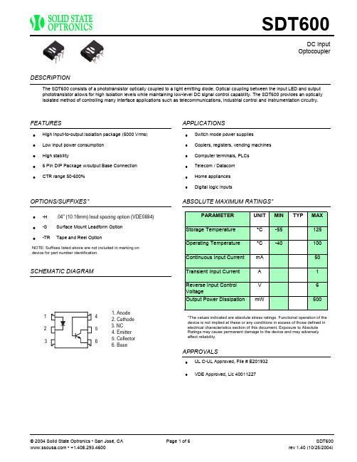
OptocouplerThe SDT600 consists of a phototransistor optically coupled to a light emitting diode. Optical coupling between the input LED and output phototransistor allows for high isolation levels while maintaining low-level DC signal control capability. The SDT600 provides an optically isolated method of controlling many interface applications such as telecommunications, industrial control and instrumentation circuitry.DESCRIPTIONFEATURES APPLICATIONSOPTIONS/SUFFIXES*SCHEMATIC DIAGRAMABSOLUTE MAXIMUM RATINGS*APPROVALSHigh input-to-output isolation package (5000 Vrms)• Low input power consumption • High stability• 6 Pin DIP Package w/output Base Connection• CTR range 50-600%•Switch mode power supplies •Copiers, registers, vending machines •Computer terminals, PLCs •Telecom / Datacom •Home appliances •Digital logic inputs•.04" (10.16mm) lead spacing option (VDE0884)• -H Surface Mount Leadform Option • -S Tape and Reel Option•-TRNOTE: Suffixes listed above are not included in marking on device for part number identification.PARAMETER UNIT MIN TYPMAX Storage Temperature °C -55125Operating Temperature °C -40100Continuous Input Current mA 50Transient Input Current A 1Reverse Input Control VoltageV 6Output Power DissipationmW500*The values indicated are absolute stress ratings. Functional operation of the device is not implied at these or any conditions in excess of those defined in electrical characteristics section of this document. Exposure to Absolute Ratings may cause permanent damage to the device and may adversely affect reliability.UL C-UL Approved, File # E201932•VDE Approved, Lic 40011227•1. Anode2. Cathode3. NC4. Emitter5. Collector6. BaseOptocouplerELECTRICAL CHARACTERISTICS - 25°CPARAMETER UNIT MIN TYP MAX TEST CONDITIONSINPUT SPECIFICATIONSForward Voltage V 1.2 1.4If = 20mAReverse Currentµ10Vr = 4VAOUTPUT SPECIFICATIONSCollector-Emitter Breakdown Voltage V60Ic = 10uAEmitter-Collector Breakdown Voltage V6Ie = 10uADark Currentµ0.1Vce = 20VAFloating Capacitance p0.61V = 0V, f=1.0MHzFSaturation Voltage V0.10.3If = 20mA, Ic = 1mACurrent Transfer Ratio%60600If = 2mA, Vce = 5VRise Timeµ5Ic = 2mA, Vcc = 5V, Rc = 100 ohmssFall Timeµ4Ic = 2mA, Vcc = 5V, Rc = 100 ohmssCOUPLED SPECIFICATIONSIsolation Voltage V5000T = 1 minuteIsolation Resistance G50ΩCTR CLASSIFICATION-A%60160-B%130260-C%200400-D%300600-E%60600Optocoupler PERFORMANCE DATAOptocoupler PERFORMANCE DATAOptocouplerMECHANICAL DIMENSIONS (in mm)6 PIN H TYPE WITH 0.4" L EAD SPACING (SDT 600-H)6PIN SURFACE MOUNT DEVICE (SDT 600-S )6 PIN DUAL IN-LINE PACKAGE (SDT 600)TOLERANCE :+ 0.25mmOptocouplerDISCLAIMERSolid State Optronics (SSO) makes no warranties or representations with regards to the completeness and accuracy of this document. SSOreserves the right to make changes to product description, specifications at any time without further notice.SSO shall not assume any liability arising out of the application or use of any product or circuit described herein. Neither circuit patentlicenses nor indemnity are expressed or implied.Except as specified in SSO's Standard Terms & Conditions, SSO disclaims liability for consequential or other damage, and we make no otherwarranty, expressed or implied, including merchantability and fitness for particular use.LIFE SUPPORT POLICYSSO does not authorize use of its devices in life support applications wherein failure or malfunction of a device may lead to personal injury ordeath. Users of SSO devices in life support applications assume all risks of such use and agree to indemnify SSO against any and alldamages resulting from such use. Life support devices are defined as devices or systems which, (a) are intended for surgical implant into thebody, or (b) support or sustain life, and (c) whose failure to perform when used properly in accordance with instructions for use can bereasonably expected to result in significant injury to the user, or (d) a critical component in any component of a life support device or systemwhose failure can be reasonably expected to cause failure of the life support device or system, or to affect its safety or effectiveness.。
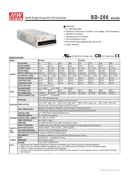
SD-200C-24中文资料
SPECIFICATIONSD-200B SD-200C MODELDC VOLTAGE RATED CURRENT CURRENT RANGE RATED POWEROUTPUTVOLTAGE ADJ. RANGE LINE REGULATION LOAD REGULATION SETUP, RISE TIME VOLTAGE RANGEEFFICIENCY (Typ.)INPUTINRUSH CURRENT (Typ.)OVER TEMPERATURE SAFETY STANDARDSEMS IMMUNITYWORKING TEMP.WORKING HUMIDITYSTORAGE TEMP., HUMIDITYTEMP. COEFFICIENT VIBRATION MTBFDIMENSION OTHERSNOTEPACKINGOVERLOADOVER VOLTAGEDC CURRENT (Typ.)5V 5V 12V 12V 24V 24V 48V 48V 34A 40A 16.7A 16.7A 8.4A 8.4A 4.2A 4.2A 0 ~ 34A 0 ~ 40A 0 ~ 16.7A 0 ~ 16.7A 0 ~ 8.4A 0 ~ 8.4A 0 ~ 4.2A 0 ~ 4.2A 170W 200W 200.4W 200.4W 201.6W 201.6W 201.6W 201.6W 100mVp-p100mVp-p 120mVp-p 120mVp-p 150mVp-p 150mVp-p 200mVp-p 200mVp-p 2.0% 2.0%1.0% 1.0%1.0% 1.0%1.0% 1.0%4.5 ~ 5.5VDC 4.5 ~ 5.5VDC 11 ~ 16VDC 11 ~ 16VDC 23 ~ 30VDC 23 ~ 30VDC 43 ~ 53VDC 43 ~ 53VDC 0.5%0.5%0.5%0.5%0.5%0.5%0.5%0.5%1.0%1.0%1.0%1.0%1.0%1.0%1.0%1.0%300ms, 50ms at full loadB:19 ~ 36VDC C:36 ~ 72VDC D:72 ~144VDC 79%81%10.8A/24V 5.4A/48V82%84%85%86%86%86%10.6A/24V 5.2A/48V10.4A/24V 6.7A/48V10.4A/24V5A/48VC:45A/48VDC D:45A/96VDC105 ~ 135%rated output power5.75 ~6.75V 5.75 ~ 6.75V16.8 ~ 20V 16.8 ~ 20V31.5 ~ 37.5V 31.5 ~ 37.5V53 ~ 65V 53 ~ 65VProtection type :Shut down o/p voltage, re-power on to recover Protection type : Shut down o/p voltage, re-power on to recover Protection type : Shut down o/p voltage, recovers automatically after temperature goes down Compliance to EN55022 (CISPR22) Class BCompliance to ight EN61000-4-2,3,4,6,8; ENV50204, l industry level, criteria A -20 ~ +60(Refer to output load derating curve)20 ~ 90% RH non-condensing -40 ~ +85, 10 ~ 95% RH0.03%/(0 ~ 5010 ~ 500Hz, 2G 10min./1cycle, 60min. each along X,Y, Z axes218.2K hrs min. MIL-HDBK-217F (25)215*115*50mm (L*W*H)1.1Kg; 12pcs/14.4Kg/0.92CUFT1. All parameters NOT specially mentioned are measured at 24,48,96VDC input, rated load and 25of ambient temperature.2. Ripple & noise are measured at 20MHz of bandwidth by using a 12" twisted pair-wire terminated with a 0.1uf & 47uf parallel capacitor.3. Tolerance : includes set up tolerance,line regulation and load regulation.4. The power supply is considered a component which will be installed into a final equipment. The final equipment must be re-confirmed that it still meets EMC directives.2:1 wide input rangeProtections: Short circuit / Overload / Over voltage / Over temperature 1500VDC I/O isolation Cooling by free air convection 100% full load burn-in test24V and 48V input voltage design refer to LVD 2 years warrantyFeatures :SAFETY &EMC(Note 4)WITHSTAND VOLTAGEISOLATION RESISTANCE I/P-O/P:1.5KVAC I/P-FG:1.5KVAC O/P-FG:0.5KVAC I/P-O/P, I/P-FG, O/P-FG:100M Ohms/500VDC EMI CONDUCTION & RADIATIONENVIRONMENT PROTECTION RIPPLE & NOISE (max.)Note.2VOLTAGE TOLERANCE Note.3955(1005for SD-200B-12 only)TSW1 detect on main power transistorUL60950-1approved (for SD-200C-24 type only), IEC60950-1 CB approved by TUV (for D type only)(for D type only)(for SD-200C-24 type only)SPECIFICATIONMODELDC VOLTAGE RATED CURRENT CURRENT RANGE RATED POWEROUTPUTVOLTAGE ADJ. RANGE LINE REGULATION LOAD REGULATION SETUP, RISE TIME VOLTAGE RANGEEFFICIENCY (Typ.)INPUTINRUSH CURRENT (Typ.)OVER TEMPERATURE SAFETY STANDARDSEMS IMMUNITY WORKING TEMP.WORKING HUMIDITYSTORAGE TEMP., HUMIDITYTEMP. COEFFICIENT VIBRATIONMTBFDIMENSION OTHERSNOTEPACKINGOVERLOADOVER VOLTAGEDC CURRENT (Typ.)Protection type :Shut down o/p voltage, re-power on to recover Protection type : Shut down o/p voltage, re-power on to recover 855(TSW1) detect on main power transistorProtection type : Shut down o/p voltage, recovers automatically after temperature goes down Compliance to EN55022 (CISPR22) Class BCompliance to ight EN61000-4-2,3,4,6,8; ENV50204, l industry level, criteria A -20 ~ +60(Refer to output load derating curve)20 ~ 90% RH non-condensing -40 ~ +85, 10 ~ 95% RH0.03%/(0 ~ 5010 ~ 500Hz, 2G 10min./1cycle, 60min. each along X,Y, Z axes 218.2K hrs min. MIL-HDBK-217F (25)215*115*50mm (L*W*H)1.1Kg; 12pcs/14.4Kg/0.92CUFTFeatures :WITHSTAND VOLTAGEISOLATION RESISTANCE I/P-O/P:1.5KVAC I/P-FG:1.5KVAC O/P-FG:0.5KVACI/P-O/P, I/P-FG, O/P-FG:100M Ohms/500VDCSAFETY &EMC(Note 4)EMI CONDUCTION & RADIATION ENVIRONMENT PROTECTION 1. All parameters NOT specially mentioned are measured at 24,48,96VDC input, rated load and 25of ambient temperature.2. Ripple & noise are measured at 20MHz of bandwidth by using a 12" twisted pair-wire terminated with a 0.1uf & 47uf parallel capacitor.3. Tolerance : includes set up tolerance,line regulation and load regulation.4. The power supply is considered a component which will be installed into a final equipment. The final equipment must be re-confirmed that it still meets EMC directives.105 ~ 135%rated output powerRIPPLE & NOISE (max.)Note.2VOLTAGE TOLERANCE Note.3SD-200D 5V 12V 24V 48V 40A 16.7A 8.4A 4.2A 0 ~ 40A 0 ~ 16.7A 0 ~ 8.4A 0 ~ 4.2A 200W 200.4W 201.6W 201.6W 100mVp-p120mVp-p 150mVp-p 200mVp-p 2.0% 1.0% 1.0% 1.0%4.5 ~ 5.5VDC 11 ~ 16VDC 23 ~ 30VDC 43 ~ 53VDC 0.5%0.5%0.5%0.5%1.0%1.0%1.0%1.0%300ms, 50ms at full loadB:19 ~ 36VDC C:36 ~ 72VDC D:72 ~144VDC 82%3.5A/96V 82%84%90%3.5A/96V3.5A/96V3.5A/96VC:45A/48VDC D:45A/96VDC5.75 ~6.75V 16.8 ~ 20V31.5 ~ 37.5V53 ~ 65V2:1 wide input rangeProtections: Short circuit / Overload / Over voltage / Over temperature 1500VDC I/O isolation Cooling by free air convection 100% full load burn-in test24V and 48V input voltage design refer to LVD 2 years warrantyIEC60950-1 CB approved by TUV (for D type only)(for D type only)Mechanical SpecificationDerating Curve Case No. 912B Unit:mmAMBIENT TEMPERATURE ()L O A D (%)10010020406080-202030405060SD-200B,C,D-5othersSD-200B-12SD-200B-24SD-200B-48Static CharacteristicsB:19C:36D:722448963672144L O A D (%)Ta=25901008070605040INPUT VOLTAGE (V)(HORIZONTAL)fosc : 100KHzBlock DiagramCIRCUITDETECTION FGO.V.P.O.L.P.CONTROLPWM FILTERINGFILTERI/PFILTERRECTIFIERSEMIFILTER&POWER SWITCH-RECTIFIERS&+V -VO.T.P.21532.513 max.4-M4 L=6mm5025150C LTerminal Pin No.Assignment :Pin No.Pin No.14,5,6327,8,9Assignment Assignment DC INPUT V+DC OUTPUT V-DC INPUT V-DC OUTPUT V+FG+V ADJ.LED 1032.5508511550.5117.515032.5177.527.58.39.55-M3 L=3mm4-M4 L=5mm 756341289。
ST200-T说明书
RB200-T智能保护装置技术说明书长园电力技术有限公司C Y G E L E C T R IC C O.,L T D目录1.装置概述 (2)1.1应用范围 (2)1.2功能特点 (2)2.技术性能指标 (3)2.1工作环境条件 (3)2.2电气技术参数 (3)3.结构与安装 (5)4.选型说明 (6)5.保护功能 (7)5.1两段定时限过流保护 (7)5.2过负荷保护 (7)5.3反时限过流保护 (7)5.4负序过流保护 (8)5.5过电压保护 (8)5.6低电压保护 (8)5.7零序定时限过流保护 (9)5.8零序反时限过流保护 (9)5.9 PT断线检测 (10)5.10开关输入量监测 (10)5.11掉电告警监测 (10)5.12事件记录 (10)6.参数设定说明 (12)6.1系统参数 (12)6.2定值参数 (12)7.人机界面使用说明 (16)7.1信号指示灯 (16)7.2小键盘 (16)7.3液晶模块显示 (17)附图1、RB200-T/1装置端子排图 (21)附图2、RB200-T/2装置端子排图 (22)1.装置概述1.1应用范围RB200-T系列装置是由专用微处理器构成的基于交流采样原理的智能保护装置,主要适用于保护10KV及以下电压等级变(配)电站中的各种一次设备,如发电机、变压器、进(馈)线、电动机、电容器、电抗器等。
1.2功能特点本装置在软硬件及结构设计上采用了最新技术,保护功能完善,性能可靠,抗干扰能力强,结构小巧,非常适合直接安装于开关柜上。
该装置主要具备以下一些特点:☆主控芯片采用美国德州仪器公司(TEXAS INSTRUMENTS)的高性能工业级、高集成度、总线不出芯片的16位微处理器,工作温度范围宽,抗干扰性能好。
☆整机全部采用贴片工业级芯片,集成度高,工作稳定可靠。
☆采用全中文简体汉字液晶显示界面,多层菜单方式显示操作,显示信息丰富,薄膜小按键操作方便。
FUJITSU ETERNUS DX200 S3 磁盘存储系统 数据手册说明书

数据手册FUJITSU ETERNUS DX200 S3磁盘存储系统适用于中小型企业或分支机构的全能存储系统ETERNUS DX——以业务为中心的存储系统FUJITSU ETERNUS DX 系列存储系统具有领先的性能架构和自动化服务管理质量,能够将存储资源与业务优先顺序相匹配,从而实现更高的系统利用率,并提供强化后的系统整合功能以及更快的投资回报(ROI)。
统一的可扩展入门级和中端系统、实现系统升级的无缝架构概念以及整个产品线上的综合管理套件 ETERNUS SF 降低了运营和迁移的成本。
ETERNUS SF 可在入门级和中端系统中提供企业级功能,并且能针对不同的型号尺寸实现灵活的灾难恢复,从而降低投资成本。
ETERNUS DX200 S3统一、可扩展的FUJITSU ETERNUS DX200 S3 存储系统拥有极佳的性价比,可为中小型企业和分支机构提供企业级功能。
针对服务器虚拟化、电子邮件、数据库、业务应用程序,以及集中文档服务整合数据时,它可成为理想的解决方案。
简单直观的系统管理、极为灵活的网络连接性以及现场升级至更高系统级别的可选特性,显著降低了运营和迁移成本。
即使是入门级系统,ETERNUS DX 系列产品架构能够让客户受益于软件选件,如自动精简配置、自动存储分层和服务管理质量。
这些因素带来了更好的业务支持。
主要特性与优势入门级系统具有极佳的性能和可扩展性⏹大量的性能和容量余量可在一个系统中针对服务器虚拟化、电子邮件和业务应用程序实现数据整合⏹系统中的高可扩展性和升级至更大系统的选件,能够在低成本增长的前提下为数据的快速提升提供支持,同时确保投资保护入门级系统具有企业级管理功能⏹ ETERNUS SF Express 管理套件特性丰富,没有额外成本⏹灵活的灾难恢复功能,不同型号尺寸的系统间能够远程复制和快照⏹操作简单高效,只需最低限度的管理真正统一的架构⏹统一的S AN 和N AS 访问驱动器系统利用率改善投资回报⏹整个产品线上的统一管理功能使得运营效率得以提高⏹统一的连接性支持大量的联网类型和多种网络组合方式⏹统一架构能够实现2.5 英寸和3.5 英寸磁盘类型的灵活组合技术规格系统概述2.5 英寸控制器机柜3.5 英寸控制器机柜控制器数量1/2主机接口数量2/4/8 个端口[FC、iSCSI、FCoE、SAS、以太网(10Gbit/s)],4/8/16 个端口[以太网(1Git/s)]高速缓存最大容量16GB(块)/16GB + 32GB(块+文件)高速缓存池800G驱动器最大数量 264驱动器机柜最大数量 10注10 个2.5英寸或3.5 英寸的D E、4个H D-DE 或混合D E不超过最大数量冗余RAID 控制器(按照2个控制器配置)风扇电源支持的R AID 级别0、1、1 + 0、5、5+0、6主机接口光纤通道(16 Gbit/s、8 Gbit/s、4 Gbit/s)FCoE (10 Gbit/s)iSCSI (10 Gbit/s、1 Gbit/s)SAS (6 Gbit/s、3 Gbit/s)以太网(10 Gbit/s、1 GBbit/s)混合主机接口是最大主机数 1,024支持的NAS协议CIFS(SMB 2.0), CIFS(SMB 3.0), NFSv2, NFSv3最大存储容量——物理容量1,584TB2.5 英寸SAS 15,000 rpm (600 GB / 300 GB)2.5 英寸SAS 10,000 rpm (1,200 GB / 900 GB / 600 GB / 300 GB)驱动器类型 2.5 英寸近线S AS 7,200 rpm (1 TB)2.5 英寸SSD (1600 GB / 800 GB / 400 GB)3.5 英寸近线S AS 7,200 rpm (6 TB / 4 TB / 3 TB / 2 TB)3.5 英寸SSD (1600 GB / 800 GB / 400 GB)HDDE, SAS 10,000 rpm (1.2TB)HDDE, 近线SAS 7,200 rpm(4 TB / 3 TB / 2 TB)注 2.5 英寸驱动器仅可用于2.5 英寸驱动器机柜,3.5 英寸驱动器仅可用于3.5 英寸驱动器机柜SSD 数量(最大)无限制混合2.5 英寸/3.5 英寸驱动器机柜是驱动器接口串联S CSI(12Gbit/s)后端磁盘连接性 1 对4通道x 12 Gbit/s 串联S CSI 总线(SAS 3.0 宽)LUN 数量(最大)4096LUN 容量(最大)128TB节能模式是自动精简配置是服务质量是业务连续性快照数量——最大2,048副本生成数量(最大)512远程复制功能同步和异步数据保护特性高速缓存保护、数据块保护、数据加密、专用热备份、磁盘驱动器、磁盘驱动器巡查、全球热备份、快速还原安全特性HTTPS(SSL)、一次性密码、RADIUS、SSH可选项存储集群Storage Cluster 是自动服务质量控制是自动存储分层是动态配置现场型号升级升级至 ETERNUS DX500 S3升级至 ETERNUS DX600 S3不间断固件升级是Raid迁移是不间断LUN在线扩展是宽条带化是热部件替换/扩展是管理接口以太网 (1000 Base-T / 100 Base-TX / 10 Base-T)支持协议SNMP (版本1、2C、3),SMI-S 1.6管理基于网络的图形用户界面,CLI(命令行界面),ETERNUS SF支持协议SNMP (版本1、2C、3),SMI-S 1.6远程支持事件通知(E-mail / SNMP / Syslog),远程维护热部件替换/扩展是支持 ETERNUS SF Express 的操作系统操作管理服务器Windows Server®2012 R2 DatacenterWindows Server®2012 R2 StandardWindows Server®2012 DatacenterWindows Server®2012 StandardWindows Server®2008 R2 DatacenterWindows Server®2008 R2 EnterpriseWindows Server®2008 R2 StandardWindows Server®2008 DatacenterWindows Server®2008 Enterprise操作管理客户端Windows® 7 Home PremiumWindows® 7 ProfessionalWindows® 7 UltimateWindows Vista® Home BasicWindows Vista® Home PremiumWindows Vista® BusinessWindows Vista® EnterpriseWindows Vista® UltimateWindows® XP Home EditionWindows® XP ProfessionalWindows Server® 2008 StandardWindows Server® 2008 EnterpriseWindows Server® 2008 DatacenterWindows Server® 2012 StandardWindows Server® 2012 DatacenterWindows Server® 2012 R2 StandardWindows Server® 2012 R2 Datacenter注其他选件见E TERNUS SF 数据手册支持配置所有主要的主机操作系统、服务器和业务应用程序详细的支持矩阵:/global/services/computing/storage/eternus/products/diskstorage/dx100/#Tab0-4安装规格19 英寸机架式是服务区域前端:850mm (33.5 英寸)或更大后端:850mm (33.5 英寸)或更大电压AC 100 - 120 V / AC 200 - 240 V电力频率50 / 60 Hz电源效率92 % (80 PLUS gold)最大功耗AC 100 - 120 V: 4,120 W (4,230 VA)AC 200 - 240 V: 4,120 W (4,230 VA)相位单相2.5 英寸控制器柜 2.5 英寸控制器柜3.5 英寸控制器柜 3.5 英寸控制器柜高密度驱动器柜最大发热量AC 200 - 240 V: 23,100: kJ/hAC 100 - 120 V: 23,100: kJ/h温度(运行)10-40℃温度(非运行)0-50℃湿度(运行)20– 80%(相对湿度、无冷凝)湿度(非运行)8– 80%(相对湿度、无冷凝)海拔3,000 m (10,000 ft.)声功率(LWAd;1B = 10dB) 6.7B声压(LpAm)49dB(A)噪音说明按照I SO 7779 用单机柜测量和按照I SO 9296 发布工作环境FTS 04230 –数据中心指南(安装规范)工作环境链接/dl.aspx?id=e4813edf-4a27-461a-8184-983092c12dbe合规产品安全UL 60950-1, CSA-C22.2 No. 60950-1, EN 60950-1, IEC 60950-1, GOST-R电磁兼容性CNS 13438, FCC CFR 47 A 类、I CES 003 A 类、EN 55022 A 类、V CCI A 类, AS/NZS CISPR 22 A 类电磁抗扰性EN55024CE 认证2004/108/EC, 2006/95/EC, 2011/65/EC批准CB, CE, C-Tick, FCC, GOST, GS, VCCI环境合规RoHS(有害物质限制指令)WEEE(废弃电子电机设备指令)合规说明总体上符合所有欧洲国家和北美的安全要求。
200t动态轨道衡技术规格书

山东石横特钢集团东阿金华钢铁有限公司炼铁技术改造公辅工程200t动态轨道衡技术规格书0版总设计师:室审:审核:设计:相关专业:山东省冶金设计院有限责任公司2022年4月27日1200t动态轨道衡技术规格书本技术规格书仅提供有限的技术要求,并未对一切技术细节做出规定,也未充分引述有关标准和规范的详细条文。
卖方提供的设备应能够满足规格书的规定,并保证符合现行国家标准、行业技术规范和标准以及买方提供的技术资料的要求。
卖方应对所提供设备的安全性、可靠性、适用性、完整性负责。
如有异议,务必在投标前会议上提出澄清。
技术规格书所使用的标准如与卖方所执行的标准发生矛盾,按较高标准执行。
1.设备编号SI1634.1.012.设备名称200t动态轨道衡3.技术数据3.1总体要求(1)卖方根据买方提供的现场环境和技术要求做出相应的200t动态轨道衡的设备设计,负责系统成套、设备供货及安装、技术培训和技术服务等工作,并对设备的完整性、可靠性、先进性负完全责任。
(2)在合同签定以后,设计方保留对卖方提供的技术资料提出补充和修改的权利,卖方应承诺予以配合。
如提出修改,具体项目和条款由设计方和卖方商定。
3.2基本技术数据:卖方根据买方提供的基本数据及技术要求,做出整体设备的配置。
3.2.1基本技术数据:(1)高炉有效容积1080m3,20个风口,2个出铁口。
(2)每个出铁口对应1个铁水罐车停车位,采用100t铁水罐车受运铁水。
(3)计量方式为动态计量。
(4)铁水罐车技术参数表见下表。
铁水罐车技术参数表电压等级为:220VAC, 50Hz±1%4.主要技术性能要求4.1 总的技术要求(1)卖方应具备动态轨道衡系统在国内外著名钢铁公司高炉上的应用具有4年以上的业绩或有良好的评价证明。
(2)卖方应具备设计、制造功能完整、质量可靠动态轨道衡的能力。
(3)卖方所供设备应根据买方要求的技术参数进行设计选型、并考虑留有适当的富余能力。
DTS200技术手册

DTS200用户手册上海华魏自动化设备有限公司二零零四年九月目录第一章,用户界面测量导论 (4)温度曲线窗口 (7)分区、报警和继电器 (12)报警窗口 (15)数据记录 (16)重放管理器 (21)命令文件传输 (22)DTS 200状态窗口 (23)级别和密码控制 (24)从屏幕打印和保存 (27)DTS 200自动启动 (28)第二章,远程控制命令远程控制界面 (30)写命令 (31)读命令 (37)系统命令....................................................... 41 第三章,操作原理DTS技术 (47)第四章,安装和维护现场要求 (52)包装 (53)线路连接 (54)功能区示意图 (57)系统安装和配置 (58)系统测试 (70)校准 (75)嵌入式软件安装 (77)INI初始化文件 (81)诊断和错误信息 (89)附件A,命令协议端口1 ASCII文本输出,York协议 (93)端口2输出数据格式,MODBUS协议 (97)-※-DTS 200用户手册第1章用户界面前言DTS200是作为一个独立于操作系统的系统而设计的,能够通过一个串行端口和/或继电器输出来提供详细而精确的测量数据。
DTS管理器配置软件具备的功能可以允许该系统用作温度测量的工具,来提供诸如温度曲线图、分区显示及数据存储等信息。
输出该系统具有两个RS232串行端口用于通信。
串行端口1与一台遥控电脑结合使用,来将设置命令发送到DTS 系统,并从该系统接收温度曲线、分区、报警及信息数据。
关于详细的通信协议描述,请参阅附件A,命令协议。
串行端口2如果用户选择了Modbus协议选项,则用来提供分区和报警数据。
继电器标准的系统配置支持32路继电器输出。
显示该系统面板上有4个指示灯ALARM用于显示火灾报警信号,此灯亮时,代表有报警信息。
SENSOR FAULT用于显示光缆故障,此灯亮时,代表光缆出故障,如断裂。
修改取样长度

TR200表面粗糙度测量仪使用说明书使用之前,请仔细阅读本说明书目录1TR200概述 (3)1.1TR200简介 (3)1.2测量原理 (3)1.3仪器主要特点 (3)1.4仪器各部分名称 (4)1.5按键定义 (6)1.6标准配置 (7)1.7传感器与主机的连接 (9)1.8开关机 (9)1.8.1软开关 (9)1.8.2硬开关 (10)1.9电池充电 (10)2系统设置 (11)2.1时钟设定 (11)2.2测量单位 (12)2.3语言选择 (12)2.4背光开/关 (13)3测量操作 (13)3.1测量前的准备 (13)3.2开机 (14)3.3触针位置 (14)3.4示值校准 (14)3.5开始测量 (15)3.6结果显示 (16)3.7存储/读取测量结果 (17)3.8打印测量结果 (18)3.9电脑显示测量结果 (19)4设置测量条件 (20)4.1修改取样长度 (20)4.2评定长度 (20)4.3滤波器 (20)4.4量程 (21)4.5主界面显示参数 (21)4.6修改测量单位 (21)4.7选择打印参数 (21)4.8设定H值 (22)4.9设定C直 (22)5日常维护和保养 (23)5.1传感器 (23)5.2主机 (23)5.3电池 (23)5.4校准样板 (23)6常见故障现象 (24)7附件 (24)7.1高度支架及传感器护套 (24)7.2测量平台 (25)7.3标准传感器 (26)7.3.1用途 (26)7.3.2各部分名称 (26)7.3.3尺寸 (26)7.3.4操作说明 (26)7.3.5示值校准 (27)7.3.6注意事项 (27)7.4曲面传感器 (28)7.4.1用途 (28)7.4.2各部分名称 (28)7.4.3尺寸 (28)7.4.4操作说明 (28)7.4.5测量 (29)7.4.6示值校准 (29)7.4.7注意事项 (29)7.5深槽传感器 (30)7.5.1用途 (30)7.5.2各部分名称 (30)7.5.3尺寸 (30)7.5.4操作说明 (31)7.5.5示值校准 (31)7.5.6注意事项 (31)7.6小孔传感器 (32)7.6.1用途 (32)7.6.2各部分名称 (32)7.6.3尺寸 (32)7.6.4操作说明 (32)7.6.5示值校准 (33)7.6.6注意事项 (33)7.7加长杆 (33)7.8微型打印机 (34)7.9PC机粗糙度测量分析软件 (34)8主要技术参数 (35)9参考信息 (36)9.1术语 (36)9.1.1术语 (36)9.1.2几种滤波器的滑行长度 (36)9.2参数定义 (37)9.2.1评定轮廓的算术平均偏差Ra (37)9.2.2评定轮廓的均方根偏差Rq (38)9.2.3轮廓的最大高度Rz (38)9.2.4轮廓的总高度Rt (38)9.2.5最大轮廓峰高Rp (38)9.2.6最大轮廓谷深Rv (39)9.2.7轮廓单峰的平均间距RS (39)9.2.8轮廓单元的平均宽度RSm (39)9.2.9轮廓微观不平度的十点高度值RzJIS (40)9.2.10轮廓的最大高度RyJIS (40)9.2.11轮廓的偏斜度Rsk (40)9.2.12峰到谷的平均高度R3z (40)9.2.13Rmax (41)9.2.14峰计数Rpc (41)9.2.15轮廓支承率曲线Rmr (42)9.2.16轮廓的支承长度率Rmr(c) (42)9.3取样长度推荐表 (43)1TR200概述1.1 TR200简介TR200表面粗糙度测量仪是适合于生产现场环境和移动测量需要的一种小型手持式仪器,它操作简便,功能全面,测量快捷,精度稳定,携带方便,能测量最新国际标准的主要参数,本仪器全面严格执行了国际标准。
TR-220 多功能测试设备数据表说明书

Specifications Subject to Change
11/4/04
Copyright © Tel-Instruments Electronics Corp.
TR-220
Transponder Test Specifications *
The TR-220 performs the following tests based on the capabilities of the transponder: Mode A - 4096 code, IDENT, percent reply, pulse spacing, pulse width Mode S Enhanced Surveillance parameters, including Selected
பைடு நூலகம்
Modes
A, C, S
Undesired replies (UF11) – Checks for reply to incorrect Mode S
interrogation Acquisition squitter – Pass/Fail indication of squitter duration, decoded
and receiver sensitivity (dBm) Decodes and displays Flight I.D.
Decodes and displays Mode S address in Octal and Hex
TCAS Test Specifications *
The TR-220 allows testing of TCAS I, TCAS II, and Traffic Advisory Systems by simulating either ATCRBS or Mode S intruders. The Setup menu allows operator to configure and store 10 TCAS scenarios, including Distance (1 to 50 NMI), Altitude (-1000 to +99,900 ft.), Vertical Speed (-7,500 to +7,500 fpm) and Velocity (100 to 1200 KTS.). The TR-220 provides a relative measurement of TCAS power and frequency.
TR200H变送器

电气设计及维修必备资料主编:冯项羽226TR200H变送器一、概述TR200H 采用先进的SMT 技术生产,外型小巧,具有高分辨率、高速、两级有源滤波功能,低功耗、超宽工作电压、多种输出形式可供选择,提供两路输出可选,适合各种应变电阻传感器,零位及放大调校皆独立不会相互影响,广泛应用于工业过程控制系统的称重信号变送为标准的高精度模拟信号输出。
二、技术规格工作电源:DC10~33V耗电量:MAX 3W工作温度:-5℃~+50℃;工作湿度:小于90%相对湿度传感器型式:所有电阻应变测力传感器或0~30mV 信号转换传感器激励:提供直流10V±1%,最大供电180mA,最多可带350Ω传感器6只输入灵敏度:信号输入0~30mV (可用于1~3mV/V 电阻应变传感器)滤波:1~90ms 可调滤波(10档可选)精度:分辨率=65000分度线性度:≤0.005%温度系数:±25ppm/℃输出:(纹波=5mvpp )第一路DC 电压输出:0~5V,1~5V,0~10V(负载电阻≥2KΩ)第二路电流输出:0~10mA ,0~20mA ,4~20mA (负载电阻≤420Ω)零位可调范围:0~20m V (十档开关+可调式电位器)量程可调范围:2~30m V (十档开关+可调式电位器)重量:约125克三、接线说明SIG+:传感器信号输入+SIG-:传感器信号输入-SHD :屏蔽EX+:激励电压输出+EX-:激励电压输出-INPUT+:直流电源输入+INPUT-:直流电源输入-电气设计及维修必备资料主编:冯项羽227OUTPUT1V+:第一路标准模拟电压信号输出正OUTPUT1V-:第一路标准模拟电压信号输出负OUTPUT2A+:第二路标准模拟电流信号输出正OUTPUT2A-:第二路标准模拟电流信号输出负四、安装接线图五、调校1、确认接线无误,检查电源电压是否正常;2、如果使用电流输出时,先选择0~20mA/4~20mA;3、空载时先调零位ZERO,粗调CO+细调FI(调到输出在零位上);4、满载时后调放大SPAN,粗调CO+细调FI(调到输出在10V 或20mA 上),如果砝码不足,在满载的30~99%(对应百分比输出即可);5、检查输出稳定性,设定滤波参数(出厂设定为2档)。
ET200pro CPU 1516PRO F-2 PN 中文名字说明书

8 kbyte 8 kbyte
64; A distributed I/O system is characterized not only by the integration of distributed I/O via PROFINET or PROFIBUS communication modules, but also by the connection of I/O via ASi master modules or links (e.g. IE/PB-Link)
Time of day Clock ● Backup time ● Deviation per day, max. Operating hours counter ● Number Clock synchronization ● supported ● in AS, master ● in AS, slave ● on Ethernet via NTP
6ES7516-2GN00-0AB0 Page 4/12
64 kbyte; max. 16 KB per block
8 192; max. number of modules / submodules
32 kbyte; All inputs are in the process image 32 kbyte; All outputs are in the process image
TR200高致软件说明书

TimeSurf For TR200 使用手册上海高致精密仪器有限公司目录1 系统的安装与卸载 (3)1.1 安装 (3)1.2 卸载 (5)1.3 注册 (6)2 与TR200通信的功能 (6)2.1 联机 (7)2.2 断开联机 (7)2.3 启动测量 (7)2.4 载入数据 (8)2.5 拾取针位 (9)2.6 配置 (9)3 数据管理功能 (10)3.1 打开文件 (10)3.2 保存文件 (11)3.3 保存数据 (11)3.4 打开数据库 (12)4 参数计算功能 (13)5 数据分析的功能 (13)5.1 未滤波曲线 (13)5.2 粗糙度曲线 (14)5.3 粗糙度和未滤波曲线 (15)5.4 支撑率曲线 (15)6 辅助功能 (16)6.1 显示辅助线 (16)6.2 隐藏辅助线 (17)6.3 缩放功能 (17)6.4 全屏显示 (18)6.5 默认视图 (18)6.6 坐标轴变化 (18)6.7 状态栏显示 (19)6.8 快捷菜单 (19)7 打印功能 (19)7.1 打印预览 (19)7.2 预览放大 (20)7.3 预览缩小 (20)7.4 关闭预览 (20)7.5 打印 (20)8 帮助功能 (21)9 登陆时代集团网站 (21)1 系统的安装与卸载1.1 安装当TimeSurf For TR200在安装时,会依次出现下面的画面:点击“next”进入系统的安装接受"许可协议",点击“next”选择程序的安装目录,点击“next”点击Install,开始安装安装成功!1.2 卸载当用户需要卸载程序,可以从windows的"控制面板"——"添加/卸载程序"中卸载程序。
如图所示:windows的控制面板卸载TimeSurf For TR200 V1.1当软件安装完毕后,运行软件会出现如下所示的窗口:点击确定按钮显示如下窗口:如果用户没有购买此软件,其可以点击“试用”按钮,这样用户可以得到免费使用5次,使用5次后此软件将不能再使用,如果用户想继续使用请与本公司联系购买此软件,已经购买此软件的用户安装好此软件后请把上面窗口中的序列号以邮件的形式发到本公司的邮箱TimeSurfpw@,我们会把注册码发回给用户,用户将注册码填入上面窗口中后点“注册”按钮后,程序将会执行,并且这个注册窗口以后将不会再出现。
- 1、下载文档前请自行甄别文档内容的完整性,平台不提供额外的编辑、内容补充、找答案等附加服务。
- 2、"仅部分预览"的文档,不可在线预览部分如存在完整性等问题,可反馈申请退款(可完整预览的文档不适用该条件!)。
- 3、如文档侵犯您的权益,请联系客服反馈,我们会尽快为您处理(人工客服工作时间:9:00-18:30)。
60000
On-State Current, It (A)
10000 Process Maximum Pulsed Currents Tj = 125 C
Involute Gate
1000 0 1 2 3 4 5 6 On-State Voltage, Vt (volts)
01k:T200ONST
MECHANICAL OUTLINE
SDT200 / T200
FULL CYCLE AVERAGE POWER
@ Tj = 125 C 60 Hz
FULL CYCLE AVERAGE POWER at TJ = 125oC Full Cycle average IT(AV) (A) 500 600 700 800 900 1000 1200 1400 1600 1800 2000 2500 3000 3200 180o half-sine PT(AV) (W) 423 544 699 798 929 1060 1335 1617 1907 2205 2511 3315 4177 4539 120o square wave PT(AV) (W) 471 599 730 865 1001 1140 1425 1719 2022 2336 2660 3516 4445 4840
ON-STATE CHARACTERISTIC
PRINCIPAL RATINGS AND CHARACTERISTICS
OPERATING JUNCTION TEMPERATURE RANGE -40 to +125oC t o . Rpttv pa of eeiie ek fVD R M sae ad rvre tt n ees VRRM 1800V vlae otg . Aeae o-tt vrg nsae I 3200A T(AV) current @TC =70oC 83m /1. m . s 00 s .Pa hl ccesre ek af yl ug I SM T cret fr V = 0 V urn o r 55.0 kA / 51.0 kA .Maximum peak recovery IM 49A R c r e t @ 2 /ms urn, A . O-tt Vlae nsae otg VT M 0.975V @ IT=2000A .Ciia rt o rs rtcl ae f ie d/t id 125A/us of current @VD =1500V .Ciia rt o rs rtcl ae f ie d/t vd 1000V/us o ofsaevlae f f-tt otg to 0 D R M .8V .unoftm (y) Tr-f ie tp t 400us q Model No. VD R M /VR R M -0oC 4 0 t + 2 oC o 15 1800 1800 1700 1700 10 60 1600 1500 1500
C L
2 0° ±5 °
THERMAL IMPEDANCE vs. ON-TIME Zthj-c (deg C/W)
.02
A Ø B Ø
.01
D
.001
B Ø
Af = 4.35 in (110.5 mm) Bf = 2.88 in (73.2 mm) D = 1.45 in (36.8 mm)
.0001
Itsm, (A) 100 Itsm I2t, (A2sec) 100 E6
10000
Peak Recovery Current Relationship with Commutating di/dt
Peak Recovery Current, Irm, (A)
1000
10 I2t
10 E6
Qrr Process Range Tj = 125 C 100
J
SDT200TR SDT200TP SDT200TM SDT200TK
C L
GATE DRIVE REQUIREMENTS Oe crutvlae/sotcrutcret pn ici otg hr ici urn 3V/3 0 A Sotcrutrstm hr ici ieie 05s .u Minimum pulse duration 10us EXTERNALLY REQUIRED CLAMPING FORCE 80 -90 ls /3. -4. k 00 00 b. 56 00 N
Average Power Pt(av) (watts) 5
4 120 deg sq wave 3
2 180 deg sine wave 1
0 0
01k:T200PTAV
500
1000 1500 2000 Average Current, It(av) (amperes)பைடு நூலகம்
2500
3000
Non-Repetitive Sub-cycle Surge Ratings with Commutating di/dt
SDT200 77mm / 1800V Thyristor
T p S T 0 r v r eb o k n t y i t r s i a l f rp a ec n r la p i a i n ,i e p c a l ye D20 ees lcig hrso, utbe o hs oto plctos s seily d s g e f rl w s o - t t v l a ed o .I i i t n e f rh a yi d s r a ,u i i ya dt a s o t eind o oet nsae otg rp t s nedd o ev nutil tlt n rnpra to srie in evc. T es l c nj n t o i m n f c u e b t ep o e m l i d f u i np o e sa di s p l e i a h iio ucin s auatrd y h rvn ut-ifso rcs n s upid n n i d s r s a d r d s - y ep c a e r a yt m u tt n t r lo f r e c o e h a d s i a o s nuty tnad ictp akg, ed o on o aua r ocd old et isptr using commercially available mechanical clamping hardware.
Rthj-case(dc) = .012 degC/watt
.00001 0.1 1 10 100 1000 10000
On-Time (milliseconds)
175 GREAT VALLEY PKWY.
MALVERN, PA 19355 USA
Rv A 1/70 pg1 e. 01/1 ae -
Tj = -40 to 125 C Vr = 0
Irm
1 1 Pulse Base Width (half sine), (msec)
01K:T200ITSM
1 E6 10
10 0.1
1 Commutating di/dt, (A/us)
10
01K:T200REC
Rev. A 10/17/01
