SPG-8650B中文资料
VP8650手册
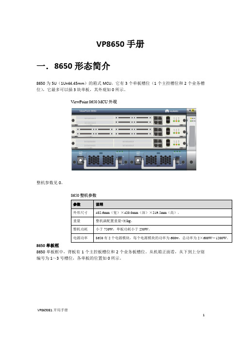
VP8650手册一.8650形态简介8650为5U(1U=44.45mm)的箱式MCU,它有3个单板槽位(1个主控槽位和2个业务槽位),它最多可以插3块单板,其外观如0所示。
ViewPoint 8650 MCU外观整机参数见0。
8650整机参数8650单板框8650单板框中,背板有1个主控板槽位和2个业务板槽位。
从机箱正面看,从下到上分别编号为1~3号槽位,各单板的位置如0所示。
8650单板槽位单板面板单板的面板示意图如0所示。
面板示意图1 E1扣板(若有E1扣板)2 扣板面板 3. FE (维护网口) 4.RS-232串口(波特率115200bps ) 5.GE0(业务网口) 6 GE1(抓包网口) 7光口:SFP1(上)、SFP0(下) 8 GCCA (单板名称) 9.ACT 指示灯 10 ALM 指示灯 11.RUN 指示灯D0~D7为扣板的数字信号处理指示灯系统状态指示灯说明123二、用命令行维护8650与8650在同一网络的任何地点均能使用Telnet 命令维护8650,维护不受时间和空间的限制。
8650暂不支持ipv6的相关配置。
●本节将以“user ”用户为例来说明Telnet 命令的使用方法。
登录8650Telnet 是Windows 操作系统内的一个外部命令,可使用两种方式进入:●在命令行模式下直接输入“Telnet ”命令,如在命令行提示符“C:>”后输入“Telnet +空格+8650的QCCA 板的GE0网口的IP 地址(缺省IP 为10.14.3.14)”,按“Enter ”键即可。
●在任务栏上单击“开始 > 运行”,在“打开”窗口内输入“Telnet +空格+8650的QCCA 板GE0网口的IP 地址(缺省IP 为10.14.3.14)”,按“Enter ”键即可。
●首次登录8650的缺省用户名为user ,缺省密码是user ,密码可修改,不区分大小写。
SGM8652中文资料
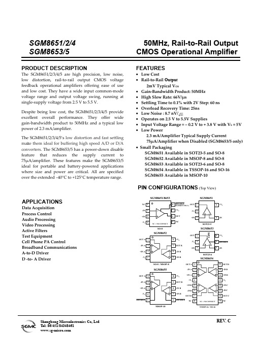
SGM8651/2/4 SGM8653/550MHz, Rail-to-Rail Output CMOS Operational AmplifierShengbang Microelectronics Co, LtdTel: 86/451/84348461 REV . CELECTRICAL CHARACTERISTICS :V S = +5V (At T A = +25℃, R L = 600Ω connected to Vs/2, unless otherwise noted)Specifications subject to change without notice.PACKAGE/ORDERING INFORMATIONMODEL CHANNEL ORDER NUMBER PACKAGE DESCRIPTIONPACKAGE OPTION MARKING INFORMATIONSGM8651XN5/TR SOT23-5 Tape and Reel, 3000 8651 SGM8651 Single SGM8651XS/TR SO-8 Tape and Reel, 2500 SGM8651XS SGM8652XMS/TR MSOP-8 Tape and Reel, 3000 SGM8652XMS SGM8652 Dual SGM8652XS/TR SO-8 Tape and Reel, 2500 SGM8652XSSGM8653XN6/TR SOT23-6 Tape and Reel, 3000 8653 SGM8653Singlewith shutdownSGM8653XS/TR SO-8 Tape and Reel, 2500 SGM8653XS SGM8654XS/TR SO-16 Tape and Reel, 2500 SGM8654XS SGM8654 Quad SGM8654XTS TSSOP-16 Tape and Reel, 3000 SGM8654XTS SGM8655Dualwith shutdownSGM8655XMS/TRMSOP-10Tape and Reel, 3000SGM8655XMSABSOLUTE MAXIMUM RATINGSSupply Voltage, V+ to V- ......................................... 7.5 V Common-Mode Input Voltage...................................... (–V S ) – 0.5 V to (+V S ) +0.5V Storage Temperature Range..................–65℃ to +150℃ Junction Temperature ..............................................160℃ Operating Temperature Range............ –55℃ to +150℃ Package Thermal Resistance @ T A = 25℃SOT23-5, θJA ......................................................... 190/W ℃ SOT23-6, θJA ......................................................... 190/W ℃ SO-8, θJA ..................................................................125/W ℃ MSOP-8, θJA .......................................................... 216/W ℃ MSOP-10, θJA ........................................................ 216/W ℃ SO-16, θJA ................................................................ 82/W ℃ TSSOP-16, θJA ....................................................... 105/W ℃ Lead Temperature Range (Soldering 10 sec)..................................................... 260℃ESD SusceptibilityHBM...........................................................................1000V MM. (400V)NOTES1. Stresses above those listed under Absolute Maximum Ratings may cause permanent damage to the device. This is a stress rating only; functional operation of the device at these or any other conditions above those indicated in the operational section of this specification is not implied. Exposure to absolute maximum rating conditions for extended periods may affect device reliability.CAUTIONThis integrated circuit can be damaged by ESD. Shengbang Micro-electronics recommends that all integrated circuits be handled with appropriate precautions. Failure to observe proper handling and installation procedures can cause damage.ESD damage can range from subtle performance degradation to complete device failure. Precision integrated circuits may be more susceptible to damage because very small parametric changes could cause the device not to meet its published specifications.TYPICAL PERFORMANCE CHARACTERISTICS At T A= +25℃, V S = +5V, G = +2, R F= 887Ω, R G = 887Ω, C L=47pF ,and R L= 600Ω, unless otherwise noted.TYPICAL PERFORMANCE CHARACTERISTICS At T A= +25℃, V S = +5V, G = +2, R F= 887Ω, R G = 887Ω, C L=47pF ,and R L= 600Ω, unless otherwise noted.TYPICAL PERFORMANCE CHARACTERISTICSAt T A= +25℃, V S = +5V, G = +2, R F= 887Ω, R G = 887Ω, and R L =150Ωconnected to Vs/2,unless otherwise noted.TYPICAL PERFORMANCE CHARACTERISTICSAt T A= +25℃, V S = +5V, G = +2, R F= 887Ω, R G = 887Ω, and R L =150Ωconnected to Vs/2,unless otherwise noted.APPLICATION NOTESDriving Capacitive LoadsThe SGM865x can directly drive 47pF in unity-gain without oscillation. The unity-gain follower (buffer) is the most sensitive configuration to capacitive loading. Direct capacitive loading reduces the phase margin of amplifiers and this results in ringing or even oscillation. Applications that require greater capacitive drive capability should use an isolation resistor between the output and the capacitive load like the circuit in Figure 1. The isolation resistor R ISO and the load capacitor C L form a zero to increase stability. The bigger the R ISO resistor value, the more stable V OUT will be. Note that this method results in a loss of gain accuracy because R ISO forms a voltage divider with the R LOAD.V IN V OUTFigure 1. Indirectly Driving Heavy Capacitive LoadAn improvement circuit is shown in Figure 2. It provides DC accuracy as well as AC stability. R F provides the DC accuracy by connecting the inverting signal with the output. C F and R Iso serve to counteract the loss of phase margin by feeding the high frequency component of the output signal back to the amplifier’s inverting input, thereby preserving phase margin in the overall feedback loop.V IN V OUTFigure 2. Indirectly Driving Heavy Capacitive Load with DC AccuracyFor no-buffer configuration, there are two others ways to increase the phase margin: (a) by increasing the amplifier’s gain or (b) by placing a capacitor in parallel with the feedback resistor to counteract the parasitic capacitance associated with inverting node. Power-Supply Bypassing and Layout The SGM865x family operates from either a single +2.7V to +5.5V supply or dual ±1.35V to ±2.75V supplies. For single-supply operation, bypass the power supply V DD with a 0.1µF ceramic capacitor which should be placed close to the V DD pin. For dual-supply operation, both the V DD and the V SS supplies should be bypassed to ground with separate 0.1µF ceramic capacitors. 2.2µF tantalum capacitor can be added for better performance.Good PC board layout techniques optimize performance by decreasing the amount of stray capacitance at the op amp’s inputs and output. To decrease stray capacitance, minimize trace lengths and widths by placing external components as close to the device as possible. Use surface-mount components whenever possible.For the high speed operational amplifier, soldering the part to the board directly is strongly recommended. Try to keep the high frequency big current loop area small to minimize the EMI (electromagnetic interfacing).VnVpV SSV SS(GND)Figure 3. Amplifier with Bypass Capacitors GroundingA ground plane layer is important for high speed circuit design. The length of the current path speed currents in an inductive ground return will create an unwanted voltage noise. Broad ground plane areas will reduce the parasitic inductance.Input-to-Output CouplingTo minimize capacitive coupling, the input and output signal traces should not be parallel. This helps reduce unwanted positive feedback.Typical Application CircuitsDifferential AmplifierThe circuit shown in Figure 4 performs the difference function. If the resistors ratios are equal ( R4 / R3 = R2 / R1 ), then V OUT = ( Vp – Vn ) × R 2 / R 1 + Vref.Vn VpOUTFigure 4. Differential AmplifierInstrumentation AmplifierThe circuit in Figure 5 performs the same function as that in Figure 4 but with the high input impedance.VnVpV OUTFigure 5. Instrumentation AmplifierLow Pass Active FilterThe low pass filter shown in Figure 6 has a DC gain of (-R 2/R 1) and the –3dB corner frequency is 1/2πR 2C. Make sure the filter is within the bandwidth of the amplifier. The Large values of feedback resistors can couple with parasitic capacitance and cause undesired effects such as ringing or oscillation inhigh-speed amplifiers. Keep resistors value as low as possible and consistent with output loading consideration.V INV OUTFigure 6. Low Pass Active FilterDriving VideoThe SGM865x can be used in video applications like in Figure 7.V INR GV OUTG = 1 + R F / R GFigure 7. Typical Video DrivingPACKAGE OUTLINE DIMENSIONS SOT23-5PACKAGE OUTLINE DIMENSIONS SOT23-6PACKAGE OUTLINE DIMENSIONS SO-8PACKAGE OUTLINE DIMENSIONS MSOP-8PACKAGE OUTLINE DIMENSIONS MSOP-10PACKAGE OUTLINE DIMENSIONS SO-16PACKAGE OUTLINE DIMENSIONS TSSOP-16REVISION HISTORYLocation Page 9/05— Data Sheet changed from REV.A to REV.BAdded SGM8655 . . . . . . . . . . . . . . . . . . . . . . . . . . . . . . . . . . . . . . . . . . . . . . . . . . . . . . . . . . . . . . . . . . . . . . .. . . . . . . Universal Changes to PRODUCT DESCRIPTION, FEATURES, and PIN CONFIGURATIONS . . . . . . . . . . .. . . . . . . . . . . . .. . 1 Changes to ELECTRICAL CHARACTERISTICS. . . . . . . . . . . . . . . . . . . . . . . . . . . . . . . . . . . . . . . . . . .. . . . . . . . . . . . . .. .2 Updated PACKAGE/ORDERING INFORMATION. . . . . . . . . . . . . . . . . . . . . . . . . . . . . . . . . . . . . . . . . .. . . . . . . . . . . . . .. .3 11/06— Data Sheet changed from REV. B to REV. CChanges to ABSOLUTE MAXIMUM ATINGS . . . . . . . . . . . . . . . . . . . . . . . . . . . . . . . .. . . . . . . . . . . . . . . . . . . . . . . . . . .. . . . . . . 3Shengbang Microelectronics Co, LtdUnit 3, ChuangYe PlazaNo.5, TaiHu Northern Street, YingBin Road Centralized Industrial ParkHarbin Development ZoneHeiLongJiang150078Harbin,ChinaP.R.Tel.: 86-451-84348461Fax: 86-451-84308461。
阳光泵业SPG系列管道屏蔽泵说明书

阳光泵业SPG系列管道屏蔽泵说明书(文章来源阳光泵业)一、概述SPG完全不泄露屏蔽泵管道泵,经我们科技人员消化革新,新推出的屏蔽泵新品,在原有基础上改进电磁核心技术,改善了流体运动状态,提高效率10%以上,综合性能指标都上了一个台阶,产品也更加理想。
SPG系列管道屏蔽泵是一种电动机和泵体一体化结构的水泵,只有静止密封(而不是旋转的轴密封),所以能做到完全无泄露。
因其电机自身低噪音,加之屏蔽泵低故障率,高可靠性能,和维护成本低等优点赢得广大用户的欢迎,也增强了对中国市场高品质水泵的需求。
二、产品特点1、SPG型屏蔽泵因能保证完全不泄漏,故可输送对人体和环境,设备有害的及价格昂贵的易泄漏的液体。
2、不会吸入空气,适于真空系统及输送与空气接触发生变质的液体。
3、无油封设计,能可靠地输送一般泵难以输送的高温,高压,低温及温度压力变化的液体。
4、轴承利用输送液体自行润滑,不需润滑油,故不污染输送液体,并免去了定期注油的麻烦。
5、泵结构合理,电机和泵同轴,体积小,重量轻,占地面积小,运行平稳,安装方便,无须调整,维修方便,无须调整,维修方便。
6、叶轮采用水推力平衡式设计,使转子在运行中可以处于悬浮设计,降低了石墨轴承的国轴向磨损,从而提高了使用寿命,降低了运行成本。
8、泵进出口法兰的规格设计与标准阀门相同,且位于同一中心线上,中心低,便于管道布置,泵房设计也便为合理,实用。
9、零部件的标准化,系列化程度高。
10、接线盒采用防水结构,可在户外安全使用。
11、可根据使用要求,即流量和扬程的需要进行泵的串,并联运行方式。
12、新采用的石墨轴承,具有耐磨性能高、磨擦系数低,不老化,抗泥沙等优点。
三、产品用途1、SPG型屏蔽泵供输送清水及物理化学性质类似于清水的其他液体之用,适用介质温度-30℃+90℃。
特别适用于工业和城市给排水,消防增压,高层建建筑增压水,园林喷灌,远距离输送暖通制冷循环,浴室等冷暖水循环增压及设备配套。
SL2.2S规格书,usb HUB大全,替换FE1.1S,GL850,GL852,PL2586
USB2.0 HUB控制器集成电路USB 2.0 HIGH SPEED 4-PORT HUB CONTROLLERSL2.2s数据手册Data Sheet内容目录第一章管脚分配 (3)1.1 SL2.2S管脚图 (3)1.2 SL2.2S管脚定义 (3)第二章 功能叙述 (5)2.1综述 (5)2.2指示灯 (5)2.2.1单灯方案 (5)2.2.2多灯方案 (6)2.2.3 LED指示定义 (6)2.3过流保护 (6)2.4充电支持 (6)2.5I2C接口 (7)2.6EEPROM设置 (7)第三章电气特性 (8)3.1极限工作条件 (8)3.2工作范围 (8)3.3直流电特性 (8)3.4HS/FS/LS电气特性 (8)3.5ESD特性 (8)附录一封装 (9)表格目录表格1: 端口LED定义 (6)表格 2 : ACTIVE LED定义 (6)表格3:EEPROM数据结构定义 (7)表格4: 最大额定值 (8)表格5: 工作范围 (8)表格6: 直流电特性 (8)插图目录图1:SSOP28 管脚图 (3)图2:单灯方案配置 (5)图3: 5灯方案配置 ............................................................................... (6)图 4:附录 封装图 ................................................................................... .9第一章管脚分配1.1SL2.2s管脚图图1:SSOP28 管脚图1.2SL2.2s管脚定义管脚名称28Die IO类型定义Pin#VSS 1 P 芯片地XOUT 2 O晶振PAD XIN 3 IDM4 4 B下行口4的USB信号DP4 5 BDM3 6 B下行口3的USB信号DP3 7 BDM2 8 B下行口2的USB信号DP2 9 BDM1 10 B下行口1的USB信号DP1 11 BVDD18 12 P 模拟1.8vVDD33 13 P 模拟3.3v - 14 NCUDM 15 B上行口的USB信号UDP 16 BRESET_N 17 I,Pu 芯片外部复位输入- 18 NCPSELF 19 I,Pu 高为自供电,低为总线供电VDD5 20 P 5v输入VDD33 21 P 3.3v输出DRV 22 B,Pu 点灯驱动信号LED1 23 B,Pu 点灯驱动信号LED2 24 B,Pu 点灯驱动信号PWRN 25 B,Pu 下行口电源输出控制,低有效OVCRN/SDA 26 B,PuI2C SDA数据线,内部上拉;芯片初始化完成后作为过流保护输入脚,低有效SCL 27 B,Pu I2C SCL时钟输出VDD18 28 P 数字1.8v注释:O,输出;I 输入;B 双向;P 电源/接地;Pu 上拉;Pd 下拉;NC 悬空;第二章 功能叙述2.1综述SL2.2s 是一颗高集成度,高性能,低功耗的USB2.0集线器主控芯片;该芯片采用STT 技术,单电源供电方式,芯片供电电压为5v , 内部集成5V 转3.3V,只需在外部电源添加滤波电容;芯片自带复位电路,低功耗技术让他更加出众。
865PE(IS8)说明书

在您安装主板以及加入硬件设备之前,请仔细阅读本手册提供的相关信息。
在使用本产品前,请确定所有的排线、电源线都已正确连接好。
若您发现有任何重大瑕疵,请尽快联络您的经销商。
为避免发生电气短路情形,请务必将所有没用到的螺丝、回形针及其他零件收好,不要遗留在主板上或电脑主机中。
灰尘、湿气以及剧烈的温度变化都会影响主板的使用寿命,因此请尽量避免放置在这些地方。
请勿将电脑主机放置在容易摇晃的地方。
若在本产品的使用上有任何的技术问题,请和经过检定或有经验的技术人员联络。
为避免可能的电击造成严重损害,在搬运电脑主机前,请先将电脑电源线暂时从电源插座中拔掉。
当您要加入硬件设备到系统中或者要去除系统中的硬件设备时,请务必先连接该设备的信号线,然后再连接电源线。
可能的话,在安装硬件设备前先拔掉电脑的电源供应器电源线。
当您要从主板连接或拔除任何的信号线前,请确定所有的电源线已事先拔掉。
如果电源供应器已损坏,请不要尝试自行修复。
请将之交给专业技术服务人员或经销商来处理。
请确认您所购买的昂达865PEN主板包装盒是否完整,如果有包装损坏或是有任何配件短缺的情形,请尽快与您的经销商联系。
☞昂达865PEN主板一块☞Ultra DMA66/100 IDE排线一根☞Serial ATA排线一根(可选)☞软驱排线一根☞驱动程序光盘一张☞本用户手册一本☞保修卡一张2.1 产品概述昂达865PEN主板采用了Intel 82865PE和82801EB芯片组,为用户提供了一个集成度高、兼容性强、性价比出众的ATX 系统平台,性能稳定,价格合理,适合于高档商业用机、家庭娱乐用。
2.2 特点介绍—板型结构ATX结构,主板尺寸为305mmX218mm—中央处理器支持478 Socket Intel Pentium 4处理器支持400/533/800MHz FSB Intel P4 478结构CPU仅支持Northwood核心的P4和Celeron4,Prescott CPU及Intel Hyper-threading(超线程技术) Pentium 4 CPU—芯片组北桥:Intel 865PE南桥:Intel 82801EB—系统存贮器4个184-PIN 的DDR内存插槽支持DDR266/333/400MHz内存支持双通道DDR内存(两个同类型内存条分别插入DIMM1&3或DIMM2&4可组成双通道,可提高内存性能)—IDE接口功能支持主从两个IDE通道和两个Serial ATA通道可连接四个独立的驱动器支持Ultra DMA 33/66/100/Serial ATA 多种硬盘传输模式—扩展槽5个32位PCI扩展卡扩充插槽—音频6 声道软声卡解码遵循AC97 v2.2规格符合PC2001 音频性能要求可以通过S-Bracket支持SPDIF输出—AGP插槽1个AGP 8X插槽支持AGP 4X/8X数据读写或传输,最高速度可达2GBps—主板I/O接口功能主芯片之间采用中心加速结构连接技术,提供了更高的数据交换带宽两个串行端口,兼容高速16550 UART模式1个并行端口,支持ECP和EPP模式2个PS/2端口(一个键盘和一个鼠标)1个红外端口1个RJ-45 LAN插孔(可选)1个软驱接口,可支持两个软盘驱动器音频插孔(Microphone, Line-in和Line-out)—8 USB2.0接口功能符合USB2.0规范,最高速度为480Mbit/sec—BIOS支持对于周边设备和扩展卡支持即插即用—板载LAN(可选)板上自带10/100M LAN接口支持10Mb/s和100Mb/s自动交换模式兼容PCI v2.2,mini PCI 1.0和板载标准—电源供电和电源管理ATX电源接口,符合ACPI 1.0b和APM 1.2规范支持Modem唤醒,网络唤醒等各种电源管理功能备注:以上位置图与您的主板布局可能存在不同,仅供参考。
UPD780024AGB-xxx-8EU中文资料

Document No. U14042EJ4V0DS00 (4th edition) Date Published December 2002 N CP(K) Printed in Japan
The mark
shows major revised points.
ቤተ መጻሕፍቲ ባይዱ
©
©
2000
µPD780021A, 780022A, 780023A, 780024A, 780021AY, 780022AY, 780023AY, 780024AY
The µPD780021A, 780022A, 780023A, and 780024A are members of the µPD780024A Subseries of the 78K/0 Series. Only selected functions of the existing µPD78054 Subseries are provided, and the serial interface is enhanced. The µPD780021AY, 780022AY, 780023AY, and 780024AY are the µPD780024A Subseries with a multimaster supporting I2C bus interface, which makes them suitable for AV equipment. Flash memory versions, the µPD78F0034A, 78F0034B, 78F0034AY, and 78F0034BY, that can operate in the same power supply voltage range as the mask ROM versions, and various development tools, are also available. Detailed function descriptions are provided in the following user’s manuals. Be sure to read them before designing. µPD780024A, 780034A, 780024AY, 780034AY Subseries User’s Manual: U14046E 78K/0 Series Instructions User’s Manual: U12326E
广州唯创电子 WTB 系列语音芯片说明书
WTB系列语音芯片使用说明书目录1、WTB芯片特征 (3)2、应用范围 (3)3、WTB系列语音芯片选型 (3)4、WTB系列语音芯片应用方框图 (4)5、封装示意图 (4)6、管脚描述 (5)6.1、WTB015/031-16P封装引脚对应表 (5)6.2、WTB015-18S封装引脚对应表 (5)6.3、WTB031-18S封装引脚对应表 (6)6.4、WTB084-20SS/20P封装引脚对应表 (7)7、电器参数 (8)8、环境绝对极限参数 (8)9、定义IO口 (9)10、控制模式 (9)10.1、按键控制模式 (9)10.1.1、脉冲可重复触发 (9)10.1.2、脉冲不可重复触发 (9)10.1.3、电平保持可循环触发 (10)10.1.4、电平保持不可循环触发 (10)10.1.5、下一曲触发 (10)10.1.6、上一曲触发 (10)10.1.7、播放/停止触发 (11)10.1.8、播放/暂停触发 (11)10.2、一线串口控制模式 (11)10.2.1、端口分配表 (11)10.2.2、发送8位数据控制形式语音地址对应关系 (12)10.2.3、发送8位数据控制形式控制时序图 (12)10.2.4、发送16位数据控制形式语音地址对应关系 (12)10.2.5、发送16位数据控制形式控制时序图 (13)10.3、三线串口控制模式 (13)10.3.1、端口分配方式 (13)10.3.2、语音地址对应关系 (13)10.3.3、三线串口控制时序 (14)11、典型应用电路 (14)11.1、WTB015/031-16P (14)11.1.1、WTB015/031-16P按键控制(PWM输出)应用电路 (14)11.1.2、WTB015/031-16P按键控制(DAC输出)应用电路 (15)11.1.3、WTB015/031-16P一线串口控制(PWM输出)应用电路 (15)11.1.4、WTB015/031-16P一线串口控制(DAC输出)应用电路 (15)11.1.5、WTB015/031-16P三线串口控制(PWM输出)应用电路 (16)11.1.6、WTB015/031-16P三线串口控制(DAC输出)应用电路 (16)11.2、WTB015/031-18S (16)11.2.1、WTB015/031-18S按键控制(PWM输出)应用电路 (16)11.2.2、WTB031-18S按键控制(DAC输出)应用电路 (17)11.2.3、WTB015/031-18S一线串口控制(PWM输出)应用电路 (17)11.2.4、WTB015/031-18S一线串口控制(DAC输出)应用电路 (17)11.2.5、WTB015/031-18S三线串口(PWM输出)应用电路 (18)11.2.6、WTB015/031-18S三线串口(DAC输出)应用电路 (18)11.3、WTB084-20SS/20P (19)11.3.1、WTB084-20SS/20P按键控制(PWM输出)应用电路 (19)11.3.2、WTB084-20SS/20P按键控制(DAC输出)应用电路 (19)11.3.3、WTB084-20SS/20P一线串口(PWM输出)应用电路 (19)11.3.4、WTB084-20SS/20P一线串口(DAC输出)应用电路 (20)11.3.5、WTB084-20SS/20P三线串口(PWM输出)应用电路 (20)11.3.6、WTB084-20SS/20P三线串口(DAC输出)应用电路 (20)12、应用范例电路 (21)12.1、电动车应用电路 (21)12.2、定时药盒应用电路 (22)13、控制程序范例 (22)13.1、一线串口(发送8位数据控制形式)控制程序范例 (22)13.2、一线串口(发送16位数据控制形式)控制程序范例 (24)13.3、三线串口控制程序范例 (27)14、封装尺寸 (29)14.1、WTB015/031-16P封装尺寸 (29)14.2、WTB015/031-18S封装尺寸 (30)15、货源信息 (31)16、说明书版本记录 (31)1、WTB芯片特征WTB语音芯片是一款低成本OTP语音芯片;工业级性能,确保产品在多种场合下正常工作;内置音频合成器的4位微型语音处理器及4位数字逻辑运算器;WTB语音芯片完备的内部资源包括EPROM、RAM和I/O端口等;可定义多路输入端和输出端;随意定义控制输入端触发功能;自动休眠功能,有效降低功耗;支持WAV音频和两通道MIDI播放;可工作于4MHz和8MHz两种震荡模式,不同模式下的音频最高采样率分别为14KHz和28KHz;WTB系列语音芯片包括WTB015、WTB031、WTB084、WTB170,其存储时间分别为15秒、31秒、84秒、170秒,目前库存有WTB015、WTB031和WTB084三种;可加载128段语音进行控制播放;单芯片方案,可掩膜投产,降低批量生产成本;支持9bit D/A和8bit PWM输出;工作电压:DC2.2V~5.5V。
S5688B中文资料
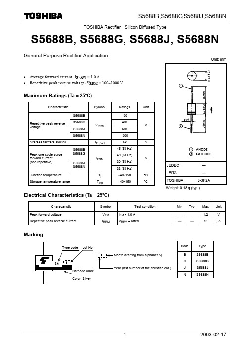
TOSHIBA Rectifier Silicon Diffused TypeS5688B, S5688G, S5688J, S5688NGeneral Purpose Rectifier Application· Average forward current: I F (AV) = 1.0 A· Repetitive peak reverse voltage: V RRM = 100~1000 VMaximum Ratings (Ta = 25°C)Characteristic Symbol RatingsUnitS5688B 100S5688G 400S5688J 600 Repetitive peak reversevoltageS5688NV RRM1000V Average forward currentI F (AV) 1.0 A45 (50 Hz) S5688B S5688G49 (60 Hz) 30 (50 Hz) Peak one cycle surge forward current (non repetitive)S5688J S5688NI FSM33 (60 Hz)AJunction temperature T j -40~150 °C Storage temperature rangeT stg-40~150 °CElectrical Characteristics (Ta = 25°C)Characteristic Symbol Test condition Min Typ. Max UnitPeak forward voltageV FM I FM = 1.0 A ¾ ¾ 1.2 V Repetitive peak reverse currentI RRMV RRM = rated¾¾ 10 m AMarkingCode Type B S5688B G S5688GJ S5688J N S5688NUnit: mmJEDEC ― JEITA―TOSHIBA 3-3F2A Weight: 0.18 g (typ.)i F - v FTa (max) - I F (AV)Surge forward current (non-repetitive)Instantaneous forward voltage v F(V)Number of cycles at 50 Hz and 60 HzTime t (s)M a x i m u m a l l o w a b l e a m b i e n t t e m p e r a t u r e T a (m a x ) (°C )I n s t a n t a n e o u s o n -s t a t e c u r r e n t i F (A )T r a n s i e n t t h e r m a l i m p e d a n c e r t h (j -a ) (°C /W )S u r g e f o r w a r d c u r r e n t I F S M (A )0.0010.010.1110 100010013 5 1010030 50 0.40.8 1.2 1.6 2.0 2.4 3.22.8· TOSHIBA is continually working to improve the quality and reliability of its products. Nevertheless, semiconductor devices in general can malfunction or fail due to their inherent electrical sensitivity and vulnerability to physical stress. It is the responsibility of the buyer, when utilizing TOSHIBA products, to comply with the standards of safety in making a safe design for the entire system, and to avoid situations in which a malfunction or failure of such TOSHIBA products could cause loss of human life, bodily injury or damage to property.In developing your designs, please ensure that TOSHIBA products are used within specified operating ranges as set forth in the most recent TOSHIBA products specifications. Also, please keep in mind the precautions and conditions set forth in the “Handling Guide for Semiconductor Devices,” or “TOSHIBA Semiconductor Reliability Handbook” etc.. · The TOSHIBA products listed in this document are intended for usage in general electronics applications (computer, personal equipment, office equipment, measuring equipment, industrial robotics, domestic appliances, etc.). These TOSHIBA products are neither intended nor warranted for usage in equipment that requires extraordinarily high quality and/or reliability or a malfunction or failure of which may cause loss of human life or bodily injury (“Unintended Usage”). Unintended Usage include atomic energy control instruments, airplane or spaceship instruments, transportation instruments, traffic signal instruments, combustion control instruments, medical instruments, all types of safety devices, etc.. Unintended Usage of TOSHIBA products listed in this document shall be made at the customer’s own risk. · The information contained herein is presented only as a guide for the applications of our products. No responsibility is assumed by TOSHIBA CORPORATION for any infringements of intellectual property or other rights of the third parties which may result from its use. No license is granted by implication or otherwise under any intellectual property or other rights of TOSHIBA CORPORATION or others. · The information contained herein is subject to change without notice.000707EAARESTRICTIONS ON PRODUCT USE。
OPB355N;OPB355L;OPB355P;OPB355T;OPB865N11;中文规格书,Datasheet资料
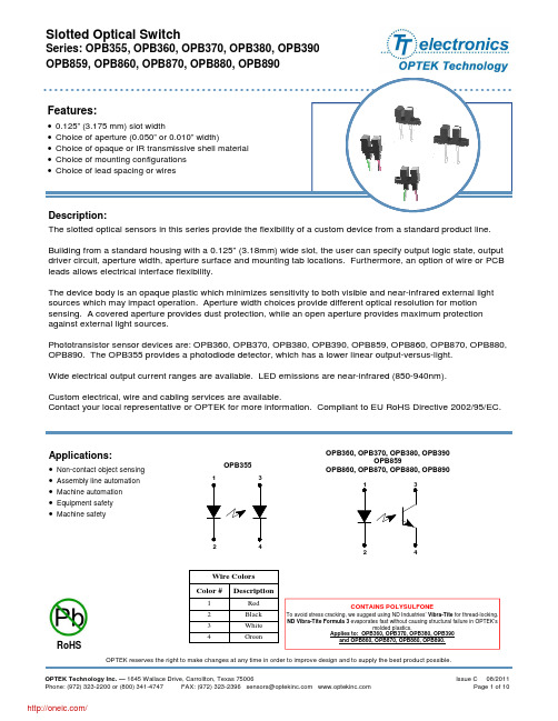
Slotted Optical SwitchSeries: OPB355, OPB360, OPB370, OPB380, OPB390 OPB859, OPB860, OPB870, OPB880, OPB890Features:• • • • •0.125” (3.175 mm) slot width Choice of aperture (0.050” or 0.010” width) Choice of opaque or IR transmissive shell material Choice of mounting configurations Choice of lead spacing or wiresProduct Photo HereDescription:The slotted optical sensors in this series provide the flexibility of a custom device from a standard product line. Building from a standard housing with a 0.125” (3.18mm) wide slot, the user can specify output logic state, output driver circuit, aperture width, aperture surface and mounting tab locations. Furthermore, an option of wire or PCB leads allows electrical interface flexibility. The device body is an opaque plastic which minimizes sensitivity to both visible and near-infrared external light sources which may impact operation. Aperture width choices provide different optical resolution for motion sensing. A covered aperture provides dust protection, while an open aperture provides maximum protection against external light sources. Phototransistor sensor devices are: OPB360, OPB370, OPB380, OPB390, OPB859, OPB860, OPB870, OPB880, OPB890. The OPB355 provides a photodiode detector, which has a lower linear output-versus-light. Wide electrical output current ranges are available. LED emissions are near-infrared (850-940nm). Custom electrical, wire and cabling services are available. Contact your local representative or OPTEK for more information. Compliant to EU RoHS Directive 2002/95/EC.Applications:• • • • •Non-contact object sensing Assembly line automation Machine automation Equipment safety Machine safety1OPB3553OPB360, OPB370, OPB380, OPB390 OPB859 OPB860, OPB870, OPB880, OPB8901 32424Wire Colors Color #1 2 3 4DescriptionRed Black White GreenCONTAINS POLYSULFONETo avoid stress cracking, we suggest using ND Industries’ Vibra-Tite for thread-locking. ND Vibra-Tite Formula 3 evaporates fast without causing structural failure in OPTEK’s molded plastics. Applies to: OPB360, OPB370, OPB380, OPB390 and OPB860, OPB870, OPB880, OPB890.RoHSOPTEK reserves the right to make changes at any time in order to improve design and to supply the best product possible. OPTEK Technology Inc. — 1645 Wallace Drive, Carrollton, Texas 75006 Phone: (972) 323-2200 or (800) 341-4747 FAX: (972) 323-2396 sensors@ Issue C 08/2011 Page 1 of 10/Slotted Optical SwitchSeries: OPB355, OPB360, OPB370, OPB380, OPB390 OPB859, OPB860, OPB870, OPB880, OPB890Part Number Guide — OPB355OPB 3 X X XOptek Assembly Phototransistor Output Family Mounting Configurations: L - Emitter side mounting tab only N - No mounting tabs P - Sensor side mounting tab only T - Two mounting tabsPart Number Guide — OPB360 / OPB370OPB 3 X X X X XOptek Assembly Sensor Aperture: 1 - 0.010” (0.254 mm) 5 - 0.050” (1.270 mm) Emitter Sensor: 1 - 0.010” (0.254 mm) 5 - 0.050” (1.270 mm) Mounting Configurations: L - Emitter side mounting tab only N - No mounting tabs P - Sensor side mounting tab only T - Two mounting tabs Lead Spacer Designator: 0 = 0.320” (8.12 mm) lead space 5 = 0.220” (5.59 mm) lead spacePhototransistor Output FamilyDiscrete Shell Material: 6 - Covered (apertures not visible), PCB leads 7 - Open (apertures visible), PCB leadsPart Number Guide — OPB380 / OPB390OPB 3 X 0 X X X ZOptek Assembly RoHS CompliantPhototransistor Output FamilySensor Aperture: 1 - 0.010” (0.254 mm) 5 - 0.050” (1.270 mm) Emitter Sensor: 1 - 0.010” (0.254 mm) 5 - 0.050” (1.270 mm) Mounting Configurations: L - Emitter side mounting tab only N - No mounting tabs P - Sensor side mounting tab only T - Two mounting tabsDiscrete Shell Material: 8 - Covered (apertures not visible), Wires 9 - Open (apertures visible), WiresOPTEK reserves the right to make changes at any time in order to improve design and to supply the best product possible. Issue C 08/2011 Page 2 of 10 OPTEK Technology Inc. — 1645 Wallace Drive, Carrollton, Texas 75006 Phone: (972) 323-2200 or (800) 341-4747 FAX: (972) 323-2396 sensors@ /Slotted Optical SwitchSeries: OPB355, OPB360, OPB370, OPB380, OPB390 OPB859, OPB860, OPB870, OPB880, OPB890Part Number Guide — OPB859OPB 8 5 9Optek Assembly Phototransistor Output Family Emitter Aperture: 0.050” (1.270 mm) Sensor Aperture: 0.050” (1.270 mm) Mounting Configurations: T - Two mounting tabsPart Number Guide — OPB860 / OPB870OPB 8 X X X X XOptek Assembly Sensor Aperture: 1 - 0.010” (0.254 mm) 5 - 0.050” (1.270 mm) Emitter Sensor: 1 - 0.010” (0.254 mm) 5 - 0.050” (1.270 mm) Mounting Configurations: L - Emitter side mounting tab only N - No mounting tabs P - Sensor side mounting tab only T - Two mounting tabsPhototransistor Output FamilyDiscrete Shell Material: 6 - Covered (apertures not visible), PCB leads 7 - Open (apertures visible), PCB leadsElectrical Specification Variations:0 = Electrical Parameter A (lead spacing = 0.320”) 1 = Electrical Parameter B (lead spacing = 0.320”) 2 = Electrical Parameter C (lead spacing = 0.320”) 5 = Electrical Parameter A (lead spacing = 0.220”) 6 = Electrical Parameter B (lead spacing = 0.220”) 7 = Electrical Parameter C (lead spacing = 0.220”) Note: Assemblies with dual 0.010” apertures are currently available with electrical parameter “A” only.Part Number Guide — OPB880 / OPB890OPB 8 X X X X X ZOptek Assembly RoHS CompliantPhototransistor Output FamilySensor Aperture: 1 - 0.010” (0.254 mm) 5 - 0.050” (1.270 mm) Emitter Sensor: 1 - 0.010” (0.254 mm) 5 - 0.050” (1.270 mm) Mounting Configurations: L - Emitter side mounting tab only N - No mounting tabs P - Sensor side mounting tab only T - Two mounting tabsDiscrete Shell Material: 8 - Covered (apertures not visible), Wires 9 - Open (apertures visible), WiresElectrical Specification Variations:0 = Electrical Parameter A 1 = Electrical Parameter B 2 = Electrical Parameter C NOTE: Assemblies with dual 0.010” apertures are currently available with electrical parameter “A” only. Wires = 26AWG - 24” long. UL approved.OPTEK reserves the right to make changes at any time in order to improve design and to supply the best product possible. OPTEK Technology Inc. — 1645 Wallace Drive, Carrollton, Texas 75006 Phone: (972) 323-2200 or (800) 341-4747 FAX: (972) 323-2396 sensors@ Issue C 08/2011 Page 3 of 10/Slotted Optical SwitchSeries: OPB355, OPB360, OPB370, OPB380, OPB390 OPB859, OPB860, OPB870, OPB880, OPB890OPB355, OPB360, OPB370, OPB860, OPB870E / Clear Top Denotes LED S / Black Top Denotes SensorOPB380, OPB390OPB859OPB880, OPB890Pin #1 2EmitterAnode CathodePin #3 4Transistor/DiodeCollector / Anode Emitter / Cathode[ MILLIMETERS] DIMENSIONS ARE IN: INCHESOPTEK reserves the right to make changes at any time in order to improve design and to supply the best product possible. Issue C 08/2011 Page 4 of 10 OPTEK Technology Inc. — 1645 Wallace Drive, Carrollton, Texas 75006 Phone: (972) 323-2200 or (800) 341-4747 FAX: (972) 323-2396 sensors@ /Slotted Optical SwitchSeries: OPB355, OPB360, OPB370, OPB380, OPB390 OPB859, OPB860, OPB870, OPB880, OPB890Absolute Maximum Ratings (TA=25°C unless otherwise noted)Storage Temperature(1) (2) OPB355, OPB360, OPB370, OPB859, OPB860, OPB870 Series OPB380, OPB390, OPB880, OPB890 Series Operating Temperature(1) (2) Lead Soldering Temperature(7)-40° C to +100° C -40° C to +85° C -40° C to +85° C 260° CInput LEDForward DC Current OPB355, OPB360, OPB370, OPB380, OPB390, OPB859, OPB860, OPB870, OPB880, OPB890 Peak Forward Current (1µs pulse width, 300 pps) Reverse DC Voltage Power Dissipation(2) 50 mA 1A 2V 75 mWOutput Phototransistor/DiodeCathode-Anode Reverse Voltage -OPB355 Collector-Emitter Voltage OPB360, OPB370, OPB380, OPB390, OPB859, OPB860, OPB870, OPB880, OPB890 Series Emitter-Collector Voltage Collector DC Current Power Dissipation(1)60 V 30 V 5V 30 mA 100 mWNotes: (1) For wire series (OPB380, OPB390, OPB880 and OPB890), maximum storage and operating temperature is limited by the temperature rating of the lead wires. (2) Derate linearly 1.67 mW/° C above 25° C. (3) For OPB355, OPB360 and OPB370, polarity is denoted by color of housing top: LED (clear); sensor (black). (4) Cleaning agents methanol and isopropanol are recommended. Spray or wipe; do not submerge. (5) OPB380 and OPB390 wire terminations have 24” of 7-strand 26 AWG UL approved insulated wire on each terminal. These devices incorporate a wire strain relief at the housing surface. The insulation colors and functions are: IRED anode (red); IRED cathode (black); phototransistor collector (white); phototransistor emitter (green). (6) RMA flux is recommended. Duration can be extended to 10 seconds maximum when flow soldering. (7) All parameters were tested using pulse technique.OPTEK reserves the right to make changes at any time in order to improve design and to supply the best product possible. OPTEK Technology Inc. — 1645 Wallace Drive, Carrollton, Texas 75006 Phone: (972) 323-2200 or (800) 341-4747 FAX: (972) 323-2396 sensors@ Issue C 08/2011 Page 5 of 10/Slotted Optical SwitchSeries: OPB355, OPB360, OPB370, OPB380, OPB390 OPB859, OPB860, OPB870, OPB880, OPB890Electrical Characteristics (TA = 25°C unless otherwise noted)SYMBOL PARAMETER MIN TYP MAX UNITS TEST CONDITIONS Input Transistor/Diode (See OP240 for additional information—for reference only) VF IR Forward Voltage Reverse Current 1.3 1.8 100 V µA IF = 20 mA VR = 2 VOutput Diode — OPB355 (See OPB950 for additional information — for reference only) VBR VFD ID Reverse Diode Breakdown Voltage Forward Voltage Photodiode Reverse Dark Current 60 1.2 60 V V nA IR = 100 µA, IF = 0, EE = 0 IF = 1 mA, IF = 0, EE = 0 VR = 30 V, EE = 0, IF = 0Output Transistor (See OP550 for additional information—for reference only) V(BR)CEO V(BR)ECO ICEO Coupled IL On-State Collector Current OPB355 (L, N, P, T) Collector-Emitter Saturation Voltage OPB859 OPB860/870/865/875 (Para. A) OPB861/871/866/876 (Para. B) OPB862/872/867/877 (Para. C) OPB880/890/ (Para. A) OPB881/891 (Para. B) OPB882/892 (Para. C) On-State Collector Current OPB36X, OPB37X (T, N, L, P 11) OPB36X, OPB37X (T, N, L, P 51) OPB36X, OPB37X (T, N, L, P 55) OPB38X, OPB39X (T, N, L, P 11) OPB38X, OPB39X (T, N, L, P 51) OPB38X, OPB39X (T, N, L, P 55) IC(ON) OPB859 OPB860/870/865/875 (Para. A) OPB861/871/866/876 (Para. B) OPB862/872/867/877 (Para. C) OPB880/890/ (Para. A) OPB881/891 (Para. B) OPB882/892 (Para. C 10 1.0 2.5 3.5 1.0 2.5 3.5 250 0.5 1.0 1.8 0.5 1.0 1.8 200 0.4 0.4 0.4 0.6 0.4 0.4 0.6 5 10 14 5 10 14 µa VR = 5 V, IF = 40 mA IC = 125 µA, IF = 20 mA IC = 400 µA, IF = 20 mA IC = 800 µA, IF = 20 mA IC = 1800 µA, IF = 20 mA IC = 400 µA, IF = 20 mA IC = 800 µA, IF = 10 mA IC = 1800 µA, IF = 20 mA Collector-Emitter Breakdown Voltage Emitter-Collector Breakdown Voltage Collector-Emitter Dark Current 30 5 100 V V nA IC = 1 mA IE = 100 µA VCE = 10 V, IF = 0, EE = 0VCE(SAT)VmAVCE = 0.4 V, IF = 20 mAµAVCE = 10 V, IF = 20 mA VCE = 10 V, IF = 20 mA VCE = 5 V, IF = 10 mA VCE = 0.6 V, IF = 20 mA VCE = 10 V, IF = 20 mA VCE = 5 V, IF = 10 mA VCE = 0.6 V, IF = 20 mAmAOPTEK reserves the right to make changes at any time in order to improve design and to supply the best product possible. Issue C 08/2011 Page 6 of 10 OPTEK Technology Inc. — 1645 Wallace Drive, Carrollton, Texas 75006 Phone: (972) 323-2200 or (800) 341-4747 FAX: (972) 323-2396 sensors@ /Slotted Optical SwitchSeries: OPB355, OPB360, OPB370, OPB380, OPB390 OPB859, OPB860, OPB870, OPB880, OPB890OPB355 - Flag Next to Emitter1.201.20OPB355 - Flag Next to SensorTop to Bottom1.001.00Top to BottomTypical IC (ON) Response (mA)0.80Typical IC (ON) Response (mA)0.80Right to Left Left to Right0.60Left to Right0.60Right to Left0.400.400.200.200.00 0.00 0.05 0.10 0.15 0.20 0.250.00 0.000.050.100.150.200.25Displacement Distance (inches)Displacement Distance (inches)OPB355 - Flag in Middle of Slot1.20Top to Bottom1.000Top to BottomTypical IC (ON) Response (mA)0.80Right to Left Left to Right0.60Emitter Left to Right Right to Left0.40Sensor 0 Width0.200.00 0.00 0.05 0.10 0.15 0.20 0.25Displacement Distance (inches)OPTEK reserves the right to make changes at any time in order to improve design and to supply the best product possible. OPTEK Technology Inc. — 1645 Wallace Drive, Carrollton, Texas 75006 Phone: (972) 323-2200 or (800) 341-4747 FAX: (972) 323-2396 sensors@ Issue C 08/2011 Page 7 of 10/Slotted Optical SwitchSeries: OPB355, OPB360, OPB370, OPB380, OPB390 OPB859, OPB860, OPB870, OPB880, OPB890Aperture Configuration 11 Next - Flag Next to Emitter OPB370T11 - Flag to Emitter1.201.20Aperture Configuration 11Next - Flag Next to Sensor OPB370T11 - Flag to SensorTop to Bottom1.001.00Top to BottomTypical IC(ON) Response (mA)0.80Typical IC(ON) Response (mA)0.80Left to RightRight to LeftLeft to RightRight to Left0.600.600.400.400.200.200.00 0.00 0.05 0.10 0.15 0.20 0.250.00 0.00 0.05 0.10 0.15 0.20 0.25Displacement Distance (inches)Displacement Distance (inches)Aperture Configuration 11 Flag inof Middle OPB370T11 - Flag in-Middle Slot of Slot1.20Top to Bottom1.000Top to BottomTypical IC(ON) Response (mA)0.80Left to RightRight to Left0.60Emitter Left to Right0.40Right to LeftSensor0.200Width0.00 0.00 0.05 0.10 0.15 0.20 0.25Diisplacement Distance (inches)OPTEK reserves the right to make changes at any time in order to improve design and to supply the best product possible. Issue C 08/2011 Page 8 of 10 OPTEK Technology Inc. — 1645 Wallace Drive, Carrollton, Texas 75006 Phone: (972) 323-2200 or (800) 341-4747 FAX: (972) 323-2396 sensors@ /Slotted Optical SwitchSeries: OPB355, OPB360, OPB370, OPB380, OPB390 OPB859, OPB860, OPB870, OPB880, OPB890Aperture Configuration 51 - Middle Flag Next Emitter OPB370N51 - Flag in of to Slot1.20 Top to BottomAperture Configuration 51Next - Flag Next to Sensor OPB370N51 - Flag to Sensor1.20Top to Bottom1.001.00Typical IC(ON) Response (mA)Typical IC(ON) Response (mA)0.80 Left to Right 0.60 Right to Left0.80 Left to Right Right to Left0.600.400.400.200.200.00 0.00 0.05 0.10 0.15 0.20 0.250.00 0.00 0.05 0.10 0.15 0.20 0.25Displacement Distance (inches)Displacement Distance (inches)Aperture Configuration 51 in - Flag in Middle of Slot OPB370N51 - Flag Middle of Slot1.20 Top to Bottom 1.000Top to BottomTypical IC(ON) Response (mA)0.80 Left to Right 0.60 Right to LeftEmitter Left to Right Right to Left0.40Sensor 0 Width0.200.00 0.00 0.05 0.10 0.15 0.20 0.25Displacement Distance (inches)OPTEK reserves the right to make changes at any time in order to improve design and to supply the best product possible. OPTEK Technology Inc. — 1645 Wallace Drive, Carrollton, Texas 75006 Phone: (972) 323-2200 or (800) 341-4747 FAX: (972) 323-2396 sensors@ Issue C 08/2011 Page 9 of 10/Slotted Optical SwitchSeries: OPB355, OPB360, OPB370, OPB380, OPB390 OPB859, OPB860, OPB870, OPB880, OPB890Aperture Configuration 55 Next - Flag Next to Emitter OPB380T55 - Flag to Emitter1.20Aperture Configuration 55Next - Flag to Sensor OPB380T55 - Flag toNext Sensor1.20 Top to Bottom 1.00Top to Bottom1.00Typical IC(ON) Response (mA)Typical IC(ON) Response (mA)0.800.80 Left to Right 0.60 Right to LeftLeft to Right0.60Right to Left0.400.400.200.200.00 0.00 0.05 0.10 0.15 0.20 0.250.00 0.00 0.05 0.10 0.15 0.20 0.25Displacement Distance (inches)Displacement Distance (inches)Aperture Configuration 55 Flag in of Middle OPB380T55 - Flag in- Middle Slot of Slot1.20Top to Bottom1.000Top to BottomTypical IC(ON) Response (mA)0.80Left to Right0.60Right to LeftEmitter Left to Right Right to Left0.40Sensor 0 Width0.200.00 0.00 0.05 0.10 0.15 0.20 0.25Displacement Distance (inches)OPTEK reserves the right to make changes at any time in order to improve design and to supply the best product possible. Issue C 08/2011 Page 10 of 10 OPTEK Technology Inc. — 1645 Wallace Drive, Carrollton, Texas 75006 Phone: (972) 323-2200 or (800) 341-4747 FAX: (972) 323-2396 sensors@ /分销商库存信息:OPTEK-TECHNOLOGYOPB355N OPB355L OPB355P OPB355T OPB865N11OPB880P51Z OPB891T51Z OPB370L51OPB370N51 OPB370P51OPB370T51OPB360N55 OPB360L55OPB360P55OPB360T55 OPB375L55OPB375N55OPB375P55 OPB375T55OPB870L55OPB870N55 OPB870P55OPB871L55OPB871N55 OPB871P55OPB871T55OPB872L55 OPB872N55OPB872P55OPB872T55 OPB365L55OPB365N55OPB365P55 OPB365T55OPB375L51OPB375N51 OPB375P51OPB375T51OPB870L51 OPB870T55OPB360L51OPB360P51 OPB360T51OPB860P55OPB861L55 OPB861P55OPB862L55OPB862P55 OPB860N55OPB860T55OPB861N55 OPB861T55OPB862N55OPB862T55 OPB370L55OPB370P55OPB370T55 OPB865L55OPB865P55OPB875P51 OPB865N55OPB865T55OPB866L55 OPB866P55OPB875L51OPB875N51 OPB875T51OPB866N55OPB866T55 OPB365N51OPB365L51OPB365P51 OPB365T51OPB860L51OPB860P51 OPB867L55OPB867P55OPB870N51 OPB870P51OPB870T51OPB860N51 OPB860T51OPB867N55OPB867T55 OPB861L51OPB861P51OPB862L51 OPB862P51OPB861N51OPB861T51 OPB862N51OPB862T51OPB871L51 OPB871N51OPB871P51OPB871T51 OPB865L51OPB865P51OPB865N51 OPB865T51OPB876L51OPB876N51 OPB876P51OPB876T51OPB877L51 OPB877N51OPB877P51OPB877T51 OPB866L51OPB866P51OPB867L51 OPB867P51OPB872L51OPB872N51 OPB872P51OPB872T51OPB866N51 OPB866T51OPB867N51OPB875N55 OPB876N55OPB877N55OPB875L55。
威盛WM8650中文说明书V0.3(7寸)

资料来源:爱购机目录................................................................................................... 错误!未定义书签。
1 外观描述 (2)2 电源键的用法 (3)3 触摸屏 (4)4转接盒 (4)5 SD卡的使用 (5)6开始使用 (5)给设备充电 (5)启动设备 (5)Wi-Fi 网络设置 (5)7桌面 (5)8锁屏界面 (6)9预装程序 (7)10桌面菜单功能 (8)11 程序管理 (10)安装程序 (10)直接从网络上下载程序 (10)卸载程序 (10)12 天气 (10)13 时钟 (11)闹钟 (11)14在线软件安装 (12)菜单功能 (12)15浏览器 (13)16 日历 (13)新建活动 (13)17 相机 (13)拍摄图片 (13)录制视频 (14)18 计算器 (14)19 电子邮件 (14)添加邮件账户 (14)收件箱 (15)编辑邮件账户 (15)删除邮件账户 (16)20 文件浏览器 (16)在电脑和设备之间拷贝文件 (17)删除文件 (17)21 我的音乐 (17)播放音乐 (17)对音乐盒播放列表进行操作 (18)22 我的视频 (18)播放视频 (18)对视频和播放列表进行操作 (19)23 我的相册 (19)涂鸦 (20)24 通讯录 (20)添加新的联系人 (20)添加联系人到收藏 (20)编辑联系人 (20)删除联系人 (20)25 图片截取 (21)26 程序管理器 (21)停止程序 (21)卸载程序 (21)27 YouTube (21)28 土豆视频 (22)29 Wi-Fi设置 (22)30 3G Settings (22)31 连接ADSL上网 (23)32 有线网络 (23)33 设置 (23)常见问题 (25)电池管理 (26)电池充电 (26)重要安全提示 (26)附录.建议可选配件及型号 (27)1 外观描述前视图:右视图:左视图:顶视图:2 电源键的用法开机: 长按电源键2秒。
SOB865660中文资料
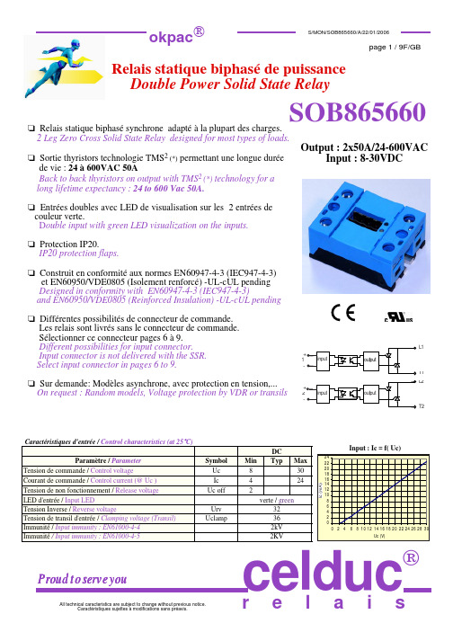
Typ. 400
Max 600 12
50 720
60 0,9 12
Unit V rms V V V A rms A V mΩ W K/W mA ,9x0,9xIe + 0,012xIe2 0,45 1 5 10 10 800 50 1500 2500
Symbol Ui Ui Ri Uimp double amplitude HR
4000 4000 1000 (@500VDC) 4000 IP20 2 1,5 30/50 -40 /+100 -40/+125 40 to 85 80 EN60947-4-3 (IEC947-4-3) VDE0805/EN60950 UL/cUL PA 6 UL94VO Aluminium, nickel-plated
Ic (mA) 24 22 20 18 16 14 12 10 8 6 4 2 0 0 2 4
Input : Ic = f( Uc)
verte / green 32 36 2kV 2KV
6 8 10 12 14 16 18 20 22 24 26 28 30 Uc (V)
Proud to serve you
VRMS VRMS MΩ V
mm g °C °C % g
pending
celduc
r e l a i s
Rue Ampère B.P. 4 42290 SORBIERS - FRANCE E-Mail : celduc-relais@ Fax +33 (0) 4 77 53 85 51 Service Commercial France Tél. : +33 (0) 4 77 53 90 20 Sales Dept.For Europe Tel. : +33 (0) 4 77 53 90 21 Sales Dept. Asia : Tél. +33 (0) 4 77 53 90 19
华为ViewPoint 8650 MCU用户指南
商标声明
、
、华为、 是华为技术有限公司的商标或者注册商标。
在本手册中以及本手册描述的产品中,出现的其他商标、产品名称、服务名称以及公司名称,由其各自的所
有人拥有。
注意 本手册描述的产品及其附件的某些特性和功能,取决于当地网络的设计和性能,以及您安装的软件。某些特 性和功能可能由于当地网络运营商或网络服务供应商不支持,或者由于当地网络的设置,或者您安装的软件 不支持而无法实现。因此,本手册中的描述可能与您购买的产品或其附件并非完全一一对应。 华为技术有限公司保留随时修改本手册中任何信息的权利,无需进行任何提前通知且不承担任何责任。
ViewPoint 8650 MCU
用户指南
华为技术有限公司
ViewPoint 8650 MCU V100布日期 部件编码
02 2010-08-16 31010BEQ
华为所有和机密 版权所有 © 华为技术有限公司
华为技术有限公司为客户提供全方位的技术支持,用户可与就近的华为办事处联系,也可直接与公司总部联 系。
版权所有 © 华为技术有限公司 2010。 保留一切权利。 非经华为技术有限公司书面同意,任何单位和个人不得擅自摘抄、复制本手册内容的部分或全部,并不得以 任何形式传播。
本手册中描述的产品中,可能包含华为技术有限公司及其可能存在的许可人享有版权的软件,除非获得相关 权利人的许可,否则,任何人不能以任何形式对前述软件进行复制、分发、修改、摘录、反编译、反汇编、 解密、反向工程、出租、转让、分许可以及其他侵犯软件版权的行为,但是适用法禁止此类限制的除外。
进出口管制 若需将此产品手册描述的产品(包含但不限于产品中的软件及技术数据等)出口、再出口或者进口,您应遵 守适用的进出口管制法律法规。
解析I芯片组

解析I芯片组您当下的位置:cs-ck个人主页/csck硬件文章解析Intel865/875芯片组图/文by濮元恺发布背景为了彻底拉开和对手AMD的距离,2002年11月中旬,Intel决定将下壹代的Pentium4处理器FSB频率跳过原计划的677MHz,直接从533MHz提升至800MHz,新Pentium4处理器由开发代号为Springdale和Canterwood的俩款芯片组提供新平台。
原有的845系列和850系列芯片组由于不支持800MHz 的FSB而分别被865(Springdale)和875(Canterwood)系列代替。
865系列分为865G、865P/PE,875系列有875P,它们将支持800MHz的FSB频率、双通道DDR400超线程技术、千兆以太网接口、SerialATA等新标准。
技术介绍Intel865/875系列支持800MHzFSB的新Pentium4处理器,FSB带宽为6.4GB/s。
为满足6.4GB/s的前端总线,Intel采用双通道的DDR400提供内存支持。
这是Intel在桌面芯片组方面首次采用双通道内存,见来服务器方面的E7205令Intel很满意,这也标志着Intel对RDRAM的彻底放弃。
Intel865/875系列提供对AGP8X的支持,使AGP带宽从1.06GB/s提升至2.1GB/s。
除了这些,Intel仍提供了许多新技术,让我们壹壹了解。
CSA接口Intel在865/875芯片组增加了壹个CSA (CommunicationsStreamingArchitecture)接口以提供对千兆以太网的支持。
千兆以太网的带宽是1000Mbps/8=125MB/s,而Intel的HubLink总线带宽是266MB/s,如果将千兆以太网接在南桥芯片上势必占用HubLink总线大量的带宽,影响PCI、ATA等接口的速度。
为了解决这个问题,Intel在北桥芯片中加入了CSA接口,它通过提供壹条带宽为266MB/s的DNB (DedicatedNetworkBus)总线,绕过PCI总线和HubLink总线,直接和北桥芯片进行数据交换,巧妙的避开了低带宽的限制,又获得了更理想的网络传输性能。
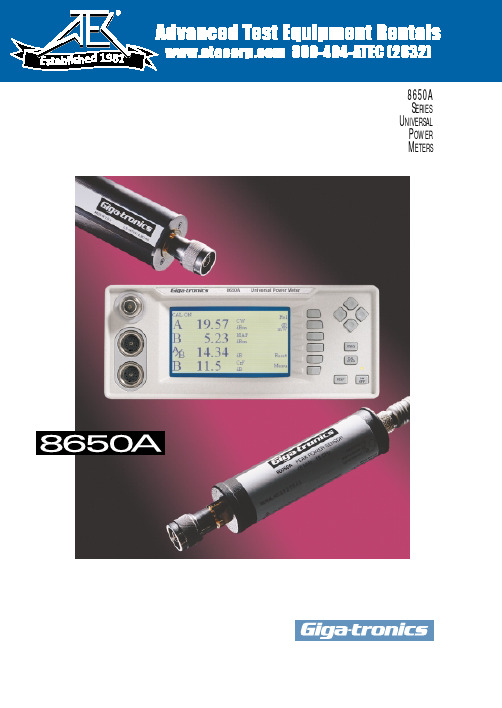
Giga-tronics 8650A系列通用电源表说明书
19818650AS ERIESU NIVERSALP OWERM ETERSThe Giga-tronics 8650A Series combines the speed,range and capabilities needed to test today’s sophisticated communications systems.sors,or from forgetting toThe Secret is the SensorsPULSE POWER MEASUREMENTS Attach a Giga-tronics 80350A Series Peak Power Sensor to an 8650A meter and directly measure the instantaneous peak power level of a pulse modulated e the ‘sample delay’ function to set the desired measurement point on the wave-form.And an external scope can be used to view the profile and see the exact measurement point on the pulse.Giga-tronics power meter architecture provides for a broad choice of functional sensors.Just by changing a sensor,you can measure CW power,pulse power,and the peak and aver-age power of TDMA,GSM and CDMA signals faster,more accurately,and over a wider range.THEFASTESTCW MEASUREMENTSGiga-tronics 80300A Series CW Power Sensors let you measure CW power from 10 MHz to 40 GHz at more than 1,750readings per second over GPIB.Measure up to 90 dB with a single sensor,and select from a variety of high power sensors,up to 50 W .MODULA TEDPOWER MEASUREMENTSThe Giga-tronics 80400A Series Modulated Power Sensors let you measure the average power of ampli-tude modulated,burst modulated and other complex modulated signals — suchas TDMA signals — at bandwidths up to 40 kHz.The Giga-tronics 80600A Series Modulated Power Sensors provide bandwidth up to 1.5 MHz to measure the peak and average power of CDMA signals.And the Giga-tronics 80701A Modulated Power Sensor operating with the 8650A power meter,provides system bandwidth up to 10 MHz to measure the peak and average power of wide band,third-genera-tion CDMA signals over an 80 dB range.Displays of IntelligenceSEE FOR YOURSELFThe 8650A incorporates a 3.72” wide by 2.15” high Liquid Crystal Display (LCD)with 240 x 120 dot resolu-tion,0.38 mm dot pitch,and Cold Cathode Fluorescent Lamp (CCFL) back light for maximum detail and opti-mum viewing.The large display lets you see more information.And the display works in tandem with the meter controls to let you view menu selections and see your input data as you enter it.Y ou can view calibration information,select a standard mode,setup and recall pre-configured,custom modes,and set measurement points and durations.Each sensor uses an EEPROM to store values of cal factor.Enteringthe measurement frequency automatically calls up the correct cal factor.If the measurement frequency is between cal factor points,the meter automatically enters an interpolated value.An extensive list of help panels provide assistance in setting up special features and guidance in making the measurement.A volts per frequency input isavailable to set the cal factor when connected to an RF source.As the source frequency is modified the V/F output will automatically set the power meter to the correct cal factor,thereby eliminating the need for manual input.Peak (Pulse) power sensors can be set to the desired measurement point of a pulse signal.The trigger point can be set using an internalpower level or a TTL signal.Recall setup can be used to pre-configure measurement modes for later use.Full descriptive details help to clearly identify the settings before recall.The graphic display provides visual feedback as you set the measurement start time and duration of the time gate to measure the average power during a specific time period.View the mean power and standard deviation of the modulated signal over a time period of interest.Standard deviation offers an alter-native descriptive analysis of the power variation when compared to the traditional crest factor.ST A TISTICAL ANAL YSISExcessive cost can prove as detrimental to the success of communications equipment as inadequate performance.The 8650A provides a range of statistical power measurement analysis fea-tures that help you optimize your designs to prevent inad-equate performance due to under design or excessive cost due to over design.These features include crest factor,standard devi-ation,strip chart,CDF/CCDF ,and histogram,and they let you view and thoroughly analyze the power signal over a selected period of time.Combined,they make the 8650A the most advanced power meter available for communications systemsdesign.The histogram function allows youto view a power range distribution over a period of time.The x axis displays the minimum to maximum power levels measured during the interval time period,and the y axis displays the percent of time each power level is measured.A zoom feature lets you view smaller seg-ments of the power range to bet-ter analyze the percentage of time a specific power level has occurred.The strip chart function allows you to view the vary-ing power levels of a signal over a period of time.The x axis displays time from the start of the meas-urement to a selectable period of 1 to 200 minutes,and the y axis displays the minimum to maximum power levels measured during the selected period.Moving a cursor along the x axis displays time and the corresponding power level.The Cumulative Distribution Function (CDF) shows the percentage of time a signal is below a selected power level.Thex axis displays the amount of power at the selected level,meas-ured in dBm,and the y axis dis-plays the percentage of time the power is at or below the power specified by the x axis.The Complementary Cumulative Distribution Function (CCDF) reori-ents the CDF curve in accordance with the equation CCDF = 1-CDF for more accustomed viewing of a descending slope.Moving a cursor along the slope of the curve dis-plays the power level in dBm and the corresponding percentage of time the signal is above that level.The K connector is electrically and mechanically compatible with the APC-3.5 and SMA connec-tors.Note:Use a Type N(m) to SMA(f) adapter (part no.29835) for calibration of power sensors with Type K(m) connectors.Power coefficient equals <0.01 dB/Watt.Power coefficient equals <0.015 dB/Watt.For frequencies above 8 GHz,add power linearity to system linearity.Power coefficient equals <0.01 dB/Watt (Average).Power coefficient equals <0.015 dB/Watt (Average).Peak operating range above CW maximum range is limited to <10% duty cycle.Square root of the sum of the individual uncertainties squared (RSS).Cal Factor numbers allow for 3% repeatability when reconnecting an attenuator to a sensor and 3% for attenuator measurement uncertainty and mismatch of sensor/pad combination.Depending on sensor used.MAP (Modulated Average Power),PAP (Pulse Average Power),BAP (Burst Average Power).Specified performance applies with maximum averaging and 24 hour warm-up at constant temperature.Operates in Normal Mode only.Display contrast reduces above 50°C.Does not apply to 80701A Sensor below 500 MHz.Specifications subject to change without notice.Specifications describe the instrument’s warranted performance,and apply when using the 80300A,80400A,80600A,and 80700A Series Sensors.METERFrequency Range:10 MHz to 40 GHz 10Power Range:-70 dBm to +47 dBm (100 pW to 50 Watt) 10Single Sensor Dynamic Range:10CW Power Sensors:90 dB Peak (Pulse) Power Sensors:40 dB,Peak50 dB,CWModulation Power Sensors:87 dB,CW80 dB,MAP/PAP 1160 dB,BAP 11Display Resolution:User selectable from 1 dB to 0.001 dB in Log mode,and from 1 to 4digits of display resolution in Linear mode.Meter FunctionsMeasurement Modes (Sensors):CW (80300A,80350A,80400A,80600A,and 80700A Series)Peak (80350A Series)MAP/PAP/BAP 11(80400A,80600A,and 80700A Series)Averaging:User selectable,auto-averaging or manual from 1-512 readings.Timed averaging from 20 ms to 20 seconds.dB Rel and Offset:Power display can be offset by -99.999 to +99.999 dB to account for external loss/gain.Configuration Storage Registers:Allows up to 20 front panel setups.Power Measurements and Display Configurations:Any two of the following channel configurations,simultaneously:A,B,A/B,B/A,A-B,B-A,DLYA,DLYB Number of Display Lines:4Sampling:CW and Modulation Mode: 2.5 to 5 MHz asynchronous Analog Bandwidth:CW Mode:≥3 kHzModulation Mode:>10 MHz Time Gating:Trigger Delay:0 to 327 ms Gate Time:10 µs to 327 ms Holdoff Time:0 to 327 ms ACCURACY50 MHz Calibrator:(Standard)Calibrator:+20 dBm to -30 dBmpower sweep calibration signal to dynamically linearize the power sensors.Connector:Type N,50 ΩFrequency:50 MHz,nominal0.0 dBm Accuracy:±1.2% worst case for one year,over temperature range of 5º to 35ºC.VSWR:<1.05 (Return Loss >33 dB) @0 dBm.1 GHz Calibrator:(Option 12)Required for 80700A Series Sensors.Calibrator:+20 dBm to -30 dBmpower sweep calibration signal to dynamically linearize power sensors.Connector:Type N,50 ΩFrequency:(Switchable):1 GHz,nominal;50 MHz,nominal0.0 dBm Accuracy:±1.2% worst case for one year,over temperature range of 5º to 35ºC.VSWR:<1.07 (Return Loss >30 dB) @0 dBm.800 MHz - 1 GHz Synthesizer Specifications:(Option 12)Power Range:+15 dBm to -30 dBm,settable in 1 dB steps.Frequency:800 MHz to 1 GHz,settable in 1 MHz steps.Power Stability:<0.1 dB/Hour Frequency Accuracy:±0.05%Instrumentation Linearity:±0.02 dB over any 20 dB range from -70 to +16 dBm.15±0.02 dB + (±0.05 dB/dB) from +16 to +20 dBm.±0.04 dB from -70 to +16 dBm.Graph shows linearity plus worst case zero set,and noise versus input powerTemperature Coefficient ofLinearity:<0.3%/ºC temperature change following Power Sweep calibration.24 hour warm-up required.Zeroing Accuracy:(CW)Zero Set:12<±50 pW,<±100 pW with80400A and 80600A Series Modulation Power Sensors.<±200 pW with 80700A Series Sensors.Zero Drift:12<±100 pW during 1 hour,<±200 pW with 80400A and 80600A Series Sensors,<±400 pW with 80700A Series Sensors.Noise:<±50 pW,<±100 pW with 80400A and 80600A Series Modulation Power Sensors.<±200 pW with 80700A Series Sensors.Measurable over any 1 minute interval after zeroing,3 standard deviations.REMOTE INPUTS/OUTPUTSV Prop F Input (BNC):Sets calibration factors using source VpropF output.13Analog Output (2) (BNC):Provides an output voltage of 0 to 10V for Channels 1 and 2 ineither Lin or Log units.13Does not operate in Swift or Buffered modes .Trigger Input (BNC):TTL trigger input signal for Swift and Fast Buffered modes.GPIB Interface:IEEE-488 and IEC-625 remote programmingRS232 Interface:Programmable serial interface,DB-9 connector GENERAL SPECIFICATIONS Temperature Range:Operating:0º to 55ºC (+32º to +131ºF)14Storage:-40ºC to 70ºC (-40º to +158ºF)Power Requirements:100/120/220/240V ±10%,48 to 440 Hz,25VA typical Physical Characteristics:Dimensions:215 mm (8.4 in) wide,89 mm (3.5 in) high,368 mm (14.5 in) deep Weight:4.55 kg (10lbs)ORDERING INFORMATION POWER METERS 8651A Single Input Universal Power Meter(includes 1 sensor cable)8652A Dual Input Universal Power Meter(includes 2 sensor cables)ACCESSORIESOne manual,one power cord.POWER METER OPTIONS 01Rack mount kit038651A Rear Panel Sensor and Calibrator Connections 048652A Rear Panel Sensor and Calibrator Connections 05Soft Carry Case07Side Mounted Carrying Handle08Transit Case,(Includes Soft Carry Case)09Dual Rack Mount Kit (with assembly instructions)10Dual Rack Mount Kit (factory assembled)12 1 GHz,50 MHz Switchable Calibrator 138651A Rear Panel Input Connector 148652A Rear Panel Input Connectors80301A 80310A 80320A 80321A 80322A 80325A 80330A80401A, 80601A (CW)80701A (CW)-70-64-60-50-40-40-30-67-64-60-54-50-40-30-30-20-57-54-50-44-40-30-20-20-10-47-44-40-34-30-20-10-100-37-34-30-24-20-100010-27-25-20-14-100101020-17-16-10-40102020-7-7061020303033101620304040131320253040445020203210-1-2-3S E N S O R ST Y P I C A L E R R O R (d B )Input, (dBm)Giga-tronics Incorporated 4650 Norris Canyon Road San Ramon,California 94583T elephone:800 726 4442 or925 328 4650T elefax:925 328 4700Web Site:© 1999 Giga-tronics IncorporatedGT-167-B。
RTBT-8650内阻测试仪说明书

RTBT-8650 蓄电池内阻测试仪使用说明书
武汉锐拓普电力设备有限公司
图 3.4 参数设置界面 如果是第一次测试某组电池,使用设置参数菜单中的新电池组,建立电池组名称,并选定相应的参数,如 果不选定参数,分析仪在测试时会自动采用默认的参数进行测试。 � 设置电池组中的电池个数(该组电池数) 仪表默认的该组电池数是 24 节,最大可以设置为 500 节。 � 设定最低电压告警值(电压下限)范围:
第五章
其它说明----------------------------------------------------------------------------------------------------------------- 26
5.1 注意事项--------------------------------------------------------------------------------------------------------------------26 5.2 技术信息支持及服务-----------------------------------------------------------------------------------------------------26
2
RTBT-8650 蓄电池内阻测试仪使用说明书
武汉锐拓普电力设备有限公司
第二章 2.1 外形
外形及接线说明
1:电池充电器接口 2:屏幕显示 3:按键 4:RS232 接口 5:夹钳、探针测试线接口 6:夹钳测试线 7:U 盘接口
图 2.1 仪表外形图 3
RTBT-8650 蓄电池内阻测试仪使用说明书 2.2 按键
1.1 综述-----------------------------------------------------------------------------------------------------------------------------1 1.2 主要功能及特点--------------------------------------------------------------------------------------------------------------1 1.3 技术指标-----------------------------------------------------------------------------------------------------------------------2 第二章 外形及接线说明---------------------------------------------------------------------------------------------------------- 3 2.1 外形-----------------------------------------------------------------------------------------------------------------------------3 2.2 按键----------------------------------------------------------------------------------------------------------------------------4 第三章 操作指南------------------------------------------------------------------------------------------------------------------- 4 3.1 开机----------------------------------------------------------------------------------------------------------------------------4 3.2 测试操作----------------------------------------------------------------------------------------------------------------------6 3.4 数据管理--------------------------------------------------------------------------------------------------------------------14 3.5 系统管理--------------------------------------------------------------------------------------------------------------------18 第四章 简易问题维修指南----------------------------------------------------------------------------------------------------- 24 II
MAX865中文资料
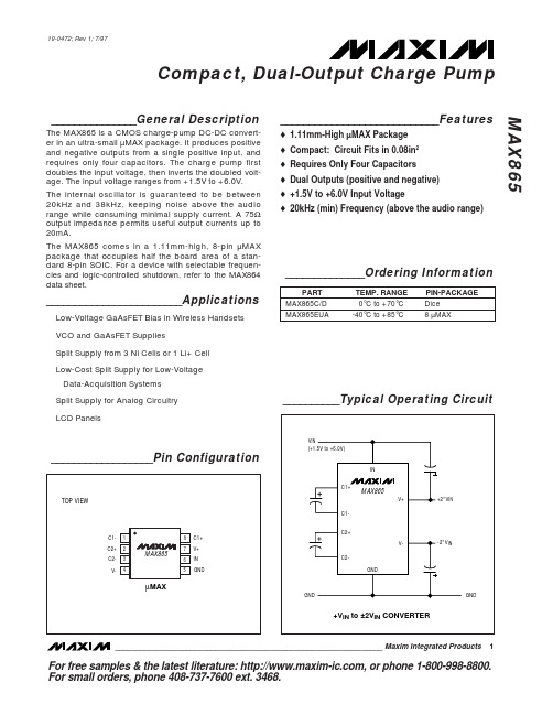
Compact, Dual-Output Charge Pump MAX865
ABSOLUTE MAXIMUM RATINGS
V+ to GND .................................................................+12V, -0.3V IN to GND .................................................................+6.2V, -0.3V V- to GND ..................................................................-12V, +0.3V V- Output Current .............................................................100mA V- Short-Circuit to GND ................................................Indefinite Continuous Power Dissipation (TA = +70°C) µMAX (derate 4.1mW/°C above +70°C) .......................330mW Operating Temperature Range MAX865EUA .....................................................-40°C to +85°C Storage Temperature Range .............................-65°C to +160°C Lead Temperature (soldering, 10sec) .............................+300°C
Giga-tronics GT-1050B微波功放器技术数据表说明书

Technical DatasheetGT-1050B Microwave Power Amplifier 2 GHz to 50 GHzBroadband High-Power Instrumentation Amplifier35527 -Rev.A / US13071135527-R e v . A / U S 130711The Giga-tronics GT-1050B Microwave Power Amplifier incorporates broadband MMIC-based architecture.These state-of-the-art amplifiers are based on solid-state parallel MMIC design with exceptionally widebandwidth and high power. The unique circuit topology is highly reliable, with performance that excels where extremes of bandwidth and power are demanded.The Giga-tronics GT-1050B Microwave Power Amplifiers provide excellent pulse fidelity, low intermodulation distortion, high linearity and superior gain flatness without the warm-up time, drift or aging issues of traveling wave tube amplifiers (TWTA). They feature low noise figure, low harmonics and spurious content, and are highly tolerant to load mismatch.1• 2 GHz to 50 GHz eliminates band switching, reduces cost and complexity • Solid-state technology for low noise, high reliability and long life•Ideal for R&D Lab, ATE Systems, Wireless Communications and Defense EW applicationsGT-1050B Microwave Power Amplifier35527-R e v . A / U S 130711The Giga-tronics GT-1050B Microwave Power Amplifier offers linear high-power amplification across multi-octave bands. Theyis ideal for testing in R&D Lab, ATE Systems, wireless communications applications and Defense EW systems. The 2 GHz to 50 GHz frequency range allows broadband testing without band switching or swapping narrow band amplifiers resulting in faster and more accurate testing.The amplifiers can be used in wireless communications and component testing wherever a highly linear amplifier is needed. These microwave power amplifiers with excellent pulse fidelity are ideal for many Aerospace and Defense applications, including EW, ECM, ECCM, radar and satellite system signal simulation and testing. The GT-1050B is an ideal ATE system building block for boosting test signals to overcome cable and connector loss whenever long cable runs are needed in assembly bays, environmental test chambers or field locations.The amplifier nominally provides 25 dB of gain over the 2 GHz to 50 GHz frequency range. The GT-1050B can be paired with a Giga-tronics 2540B 40 GHz Microwave Signal Generator or with Giga-tronics 2550B 50 GHz Microwave Signal Generator, increasing the overall output power while preserving the synthesizer’s fast switching speed, modulation, and high signal fidelity.2GT-1050B Microwave Power Amplifier35527-R e v . A / U S 130711Frequency RangeGT-1050B2 GHz to 50 GHzOutput PowerOutput power is specified as minimum saturated power into 50 Ohm load with +5 dBm input, at 23°C ± 5°C Input power for normal operation should be limited to +20 dBm maximum.Range Specifications2 to 10 GHz +30 dBm (1 Watts) nominal, +26 dBm (400 mW) minimum 10 to 30 GHz +28 dBm (600 mW) nominal, +25 dBm (300 mW) minimum 30 to 40 GHz +27 dBm (500 mW) nominal, +23 dBm (200 mW) minimum 40 to 50 GHz+24 dBm (250 mW) nominal, +20 dBm (100 mW) minimumGain FlatnessNominal gain is 25 dB, minimum gain > 20 dB.Gain flatness is specified as maximum variation with -5 dBm input and 50 Ohm load.Range Specifications 2 to 40 GHz ± 2.5 dB nominal 2 to 50 GHz± 3.5 dB nominal3GT-1050B Microwave Power Amplifier35527-R e v . A / U S 1307114Input and Output VSWR2 to 30 GHz30 to 40 GHz 40 to 50 GHz Input, 50 ohms 1.5:1 nominal 2.0:1 nominal 2.3:1 nominal Output, 50 ohms2.0:1 nominal2.3:1 nominal2.9:1 nominalAdditional SpecificationsParameter Specifications StabilityUnconditionally Stable Maximum Load VSWR 3:1Maximum Input Power +20 dBm Third Order Intercept +37 dBm nominal Harmonic Distortion*< -30 dBc nominal Spurious*< -60 dBc nominal Reverse Isolation > 50 dBNoise Figure< 10 dB nominal, < 14 dB maximum* Note: Harmonics measured at +10 dBm output power. Spurious measured at -5 dBm input power levelGeneral SpecificationsLine Voltage 100 to 240 VAC, 47 to 63 Hz, Single Phase Line Power20 VA maximum Operating Temperature 0°C to +50°C Storage Temperature -20°C to +75°CDimensions 2.5” H x 6.8” D x 7.0” W (64 mm H x 173 mm D x 178 mm W) Weight 4.5 lbs (2 kg)RF ConnectorsInput: 2.4 mm compatible 1.85 mm (f) V connectorOutput: 2.4 mm compatible 1.85 mm (f) V connectorGT-1050B Microwave Power Amplifier35527-R e v . A / U S 130711Ordering InformationGiga-tronics has a network of RF and Microwave instrumentation sales engineers and a staff of factory support personnel to help you find the best, most economical instrument for your specific applications. In addition to helping you select the best instrument for your needs, our staff can provide quotations, assist you in placing orders, and do everything necessary to ensure that your business transactions with Giga-tronics are handled efficiently.Model NumberFrequency RangeGT-1050BMicrowave Power Amplifier, 2 GHz to 50 GHzAvailable Options and Accessories Option Description46Add Rack Mount KitGiga-tronics Support ServicesAt Giga-tronics, we understand the challenges you face. Our support services begin from the moment you call us. We help you achieve both top-line growth and bottom-line efficiencies by working to identify your precise needs and implement smart and result orientated solutions. We believe and commit ourselves in providing you with more than our superior test solutions. For technical support, contact:Tel: 1-800-726-GIGA (4442) or (925) 328-4669Email:***********************UpdatesAll data is subject to change without notice. For the latest information on Giga-tronics products and applications, please visit out website:535527-R e v . A / U S 130711©2013 Giga-tronics Incorporated. All Rights Reserved. All trademarks are the property of their respective owners.。
广带LDMOS驱动芯片数据手册说明书

BLP10H605
Broadband LDMOS driver transistor
5. Recommended operating conditions
See application note AN11520 for more details.
150 Tcase (°C)
130
aaa-012031
Typ [1] 5.5
Unit K/W
7. Characteristics
Table 6. DC characteristics Tj = 25 C; unless otherwise specified.
Symbol Parameter
Conditions
V(BR)DSS drain-source breakdown voltage
Component layout
BLP10H605#4
Product data sheet
All information provided in this document is subject to legal disclaimers.
Rev. 4 — 1 September 2015
© Ampleon The Netherlands B.V. 2015. All rights reserved.
-
150 C
BLP10H605#4
Product data sheet
All information provided in this document is subject to legal disclaimers.
Rev. 4 — 1 September 2015
© Ampleon The Netherlands B.V. 2015. All rights reserved.
SPG玻璃放电管SPMB系列
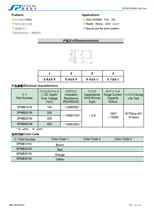
FeaturesApplications反应速度快50ns ADSL MODEM 、FAX 、TEL 体积小,贴片封装RS485、RS232、CAN 一级防护能流能力大Security and fire alarm systems静态电容量小,绝缘性好12342.6±0.35.0±0.50.4±0.12.7±0.1型号Part Number直流起始放电电压DC Spark-Over VoltageVs(V)绝缘阻抗I nsulation Resistance IR(OHM)/DC 电容量Capacitance 1KHZ-6VmaxC(pf)耐冲击电流Surge Current Capacity 8/20us寿命测试Sureg Life Test 产品尺寸/Dimensions(mm)产品参数/Electrical characteristics项目Test Item 直流放电电压DC-Spark-Over Voltage Vs内绝缘电阻Insulation Resistance静态电容Capacitance C(pF)实验项目Test Item放置于-40℃±3℃的环境中1000小时后,取出置于在规定的设定直流电压下,跨在两端引线。
即可测量其内绝缘电阻值。
(Measure the insulationresistance of two end of leadwire under thespecified DC voltage.)大于等于100M Ω(100M Ωmin.)使用频率1KHz与并两端加载小于或等于6V直流电压的电源。
即可量出其静态电容量Measure the Electrostatic Capacitance under the test conditionof 1KHz,DC 6V(max).小于或等于1pF (1pF max.)环境试验测试/Enviromental Characteristics 试验方法Test Method结果Specification基本参数特性测试/Initial Characteristics 测试条件Test Method结果Specification使用一直流电源,并逐渐地增加测量电压,测试电流为1ma ,测试时间最大为一秒(1sec ).(1mA)(Add and measure the DCVoltage gradually Maxto get the dischargethreshold voltage.The measuring current is 1mA/1second max.)依规格书值而定(It depands on each spec.)耐寒性耐热性耐温性温度周期-40℃±3℃(30分)~(常温3分)~125℃±2℃(30分)为1周期,重复25次后,取出置于常温/常温中4小时后,检测直流放电电压,绝缘阻抗,静态电容量及检查外观25times repetition of cycle -40±3℃(30Min.),roon temp.,(4Min.),125±2℃(30Min.),room temp.,normal humidity(4hrs).满足各个特性相关参数值Within standard mentioned inInitial Characteristics.常温中4小时后,检测直流开始放电电压,绝缘阻抗,静态电容量及检查外。
