Analysis Toolkit for Code Composer Studio v2.3 User's Guide (Rev. C)
Code Composer Studio 教程(五)
百度文库专用百度文库专用Code Composer Studio 教程(五)——实时性能分析在此教程中,你对程序进行实时性能分析和恰当的时序安排。
使用RTDX(real-time data exchange ——实时数据交换)对目标进行实时改变,使用DSP/BIOS周期函数,并设置软中断优先权。
此教程需要一物理板而不能用一软件仿真器来实现。
同时,也需要CCS的DSP/BIOS和RTDX部分。
步骤1:打开并检查项目1)建立工作文件夹,编译文件,并创建下列文件:①volume.c:源文件,允许你在不停止目标程序运行的情况下使用RTDX来改变load。
②loadctrl.exe:用VB5.0编写的一个简单的窗口应用程序,它实时地用RTDX将load值送到目标。
③loadctrl.frm,loadctrl.frx,loadctrl.vbp:如果你已掌握了VB,就可以用VB来检查loadctrl.exe应用程序的这些源文件。
2)进入CCS,打开项目。
步骤2:修改配置文件在此,需加一个新的对象在配置文件中。
1)打开文件volume.cdb。
2)选择LOG_system,改变buflen特性为512 words,确定。
3)在PRD管理器上右击,选择Insert PRD。
4)将PRD0改名为loadchange_PRD。
5)在loadchange_PRD对象上右击,选择properties项。
6)将period(ticks)框中改为2,function框中改为_loadchange,确定。
①将period变默认值为2,PRD管理器用CLK管理器来驱动PRD的执行。
CLK类的。
默认特性每毫秒产生一个时钟中断来触发一个PRD标记。
因此,此PRD对象每2毫秒运行一次其函数。
②改变function为_loadchange。
每个period,此PRD对象执行一次loadchange C函数。
7)打开SWI管理器。
一个SWI对象PRD_SWI已自动加入。
实验一:Code Composer Studio 入门实验
一.实验目的1.掌握Code Composer Studio 2.2 的安装和配置。
2.了解DSP 开发系统和计算机与目标系统的连接方法。
3.了解CodeComposerStudio2.2 软件的操作环境和基本功能,及TMS320C6x 软件开发过程。
(1)学习创建工程和管理工程的方法。
(2)了解基本的编译和调试功能。
(3)学习使用观察窗口。
(4)了解图形功能的使用。
二.实验设备1.PC 兼容机一台;操作系统为Windows2000 (或WindowsXP,以下假定操作系统为Windows2000)。
Windows 操作系统的内核如果是NT 的应安装相应的补丁程序(如:Windows2000 为Service Pack3 以上,WindowsXP 为Service Pack1 以上)。
2.ICETEK-C6713-USB-EDU(或ICETEK-C6713-PP-EDU)实验箱一台。
如无实验箱则配备ICETEK-ICETEK-USB 仿真器3.USB 连接电缆一条。
三.实验原理*开发TMS320C6x 应用系统一般需要以下几个调试工具来完成:-软件集成开发环境(Code Composer Studio 2.2):完成系统的软件开发,进行软件和硬件仿真调试。
它也是硬件调试的辅助手段。
-开发系统(ICETEK 5100 USB 或ICETEK 5100 PP):实现硬件仿真调试时与硬件系统的通信,控制和读取硬件系统的状态和数据。
-评估模块(ICETEK C6713-A 等):提供软件运行和调试的平台和用户系统开发的参照。
*Code Composer Studio 2.2 主要完成系统的软件开发和调试。
它提供一整套的程序编制、维护、编译、调试环境,能将汇编语言和C 语言程序编译连接生成COFF (公共目标文件)格式的可执行文件,并能将程序下载到目标DSP 上运行调试。
*用户系统的软件部分可以由Code Composer Studio 建立的工程文件进行管理,工程文件一般包含以下几种文件:-源程序文件:C 语言或汇编语言文件(*.ASM 或*.C)-头文件(*.H)-命令文件(*.CMD)-库文件(*.LIB,*.OBJ)四.实验步骤1.实验准备(1)连接实验设备①检查并设置ICETEK-C6713-EDU 实验箱的各电源开关均处于关闭状态;连接实验箱提供的220V 电源线,保证接地良好。
4、集成环境Code Composer Studio、DSPBIOS及实时调试
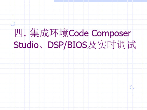
Classic Code Debugging
.out Executable Classic Debugger • • • • • Breakpoints Single step Registers Memory Disassembly
Emulator Interface Logic Analyzer Target System
DSP/BIOS II + CSL
TMS320 Algorithm Standard v2.2 Enhanced IDE Advanced Emulation
c55x Simulation Support
c64x Simulation Support Compiler Ease of Use --PBC and VL--
Extended Tektronix Intel MCS86 Motorola Exorciser TI SDSMAC
CCS Project
File Edit View Project Options
C source
Build
Linker
.map .out
ASM source Header and Include files
Simulator
CCS Debugging Workspace
File Edit View Project Debug Profiler Option My_Menu
•Create custom menu items •GEL files
• Monitor CPU consumption • Optimize code
Integrated Development Environment (IDE)
TI推出Code Composer Studio工具与全新有刷直流电机参考设计
C 5 5指 纹 开 发 套 件 提 供 快 速 准 确 的指 纹 匹 配 功 能 , 51
p e ms to. ( 稿 用 ar eec c 投 专 ) pห้องสมุดไป่ตู้ n. r n n
Mcc t1 s me eS t s i。no r&E b d sm 8 r。 re 1 d d ye 7
加小巧 , 池寿命更长 。 电 MC 1 4 稳 压 器 的工 作 电 压 低 至 0 3 启 动 电 压 P 60 . 5V, 为 0 6 即使 是 电力 耗 尽 的 单 节 碱 性 、 氢 或 镍 镉 电 池 . 5V, 镍 也 能 将其 启 动运 行 。P M/ F 选 项 可 实 现 器 件 的低 静 W PM 态 电 流 和关 断 电流 , 实 现 高 达 9 % 的 效 率 , 长 了 电池 并 6 延 的使 用 时 间 。该 稳 压 器 的两 个 集 成 式 F T 晶 体 管 减 少 了 E
( S ) 专 用 集 成 电路 ( I 方 案 。 目前 , 业 设 备 开 AS P 或 AS C) 工 发 商 能 通 过 单 个 S atn一6F GA, 松 地 在 工 业 网 络 和 p ra P 轻 自动 化 系 统 中 集 成 多 个 以 太 网 协 议 和 定 制 处 理 算 法 。 该
赛 灵 思 针 对 工 业 自动化 简化
实 时 以太 网 网 络开 发
赛 灵 思 公 司 ( l x,I c ) 出专 门针 对 工 业 自动 化 Xin i n.推
系统 设 计 优 化 的特 定 市 场 目标 设 计 平 台 。该 平 台 基 于 赛 灵 思 低 成 本 、 功 耗 S atn一6 现 场 可 编 程 门 阵 列 低 pra
WIN7下CCS3.3的安装使用说明
双击桌面的 CCSV3.3. ico
,进入 CCS 环境
选择 File->Launch Setup,进入下图
双击“C5416 Device Simulator”,进行适当的 System Configuration, 点击”Save&Quit”
出现下图,选择“是”
3.2.2 Code Composer Studio V3.3 新建一个工程
1. 课程设计题目: YUV 彩色图像处理之汉字叠加
2. 课程设计基本要求
2.1. 课程设计原理
汉字叠加就是在原始图像相应的行列中加入汉字码,首先利用 PCtoLCD 字模软件取出相应的字库,然后根据汉字码中的值,判断每个 字节的每一位是否为 1,如为 1 则将图像中的值设定为 255,改变成颜色, 为 0 则不变,在这里要注意的是原始图像的大小。彩色图像的产生是由 matlab 进行取点,生成相应的.dat,有 CCS 软件仿真图形。
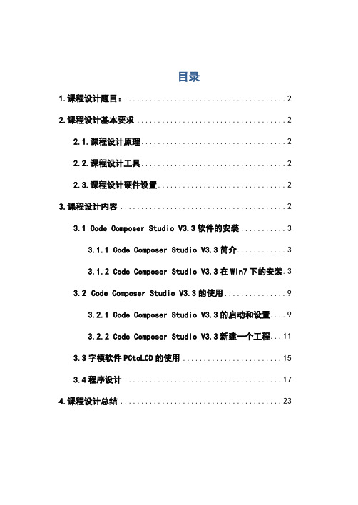
目录
1.课程设计题目: ......................................2 2.课程设计基本要求 ....................................2
2.1.课程设计原理 ...................................2 2.2.课程设计工具 ...................................2 2.3.课程设计硬件设置 ...............................2 3.课程设计内容 ........................................2 3.1 Code Composer Studio V3.3 软件的安装 ...........3
静态代码分析的工具和技巧
静态代码分析的工具和技巧静态代码分析是一种通过分析程序源代码来发现潜在缺陷的技术。
这种技术可以帮助开发人员在编写代码时找出实际的缺陷,从而提高代码质量。
在本文中,我将介绍一些常见的静态代码分析工具和技巧,帮助您写出更高质量的代码。
1. 工具1.1 SonarQubeSonarQube是一款开源的代码质量管理平台,它支持多种语言和规则集。
它可以检测出很多种类型的缺陷,包括潜在的安全漏洞、复杂度问题、代码重复和测试覆盖率。
SonarQube可以通过集成到开发环境或CI/CD流水线来实现持续集成和持续交付。
1.2 CheckstyleCheckstyle是一种Java代码静态分析工具,它可以引导开发人员编写符合标准的Java代码。
它提供了一组预定义的规则,可以检查代码风格、命名约定和注释。
Checkstyle还可以根据使用情况定制规则。
该工具可与Maven等构建工具一起使用。
1.3 PMDPMD是一种用于Java、JavaScript、PLSQL和Apex代码的静态代码分析工具。
它可以检查代码风格、找到不必要的复杂性和潜在的错误。
PMD还可以通过自定义规则扩展。
2.1 静态分析最佳实践当使用静态分析工具时,有几个优秀的实践可以提高其效果。
- 集成:将静态分析工具集成到CI/CD流水线中可以自动检测代码库和代码拉取请求,确保代码在合并到主分支之前已经通过了代码审查和自动化测试。
- 最小化噪声:将静态分析工具的配置调整为尽可能少的产生误报告的级别。
这可以减少开发人员在修复代码之前需要查看的错误数量。
- 持续改进:定期审查并修改静态分析工具输出,以改进其准确性和实用性。
2.2 分析库和框架的源码当使用第三方库或框架时,它们的源码可能潜藏Bug。
使用静态代码分析工具可以检测其源码中的风格和边界情况,以保证您的代码和库的交互安全。
2.3 立即修复缺陷当发现代码缺陷时,应立即修复。
立即修复缺陷可以减少在代码迭代和更改时遇到的麻烦,并降低测试难度。
Code Composer Studio (CCStudio) 集成开发环境
Code Composer Studio (CCStudio) 集成开发环境(IDE) v4.x 状态: ACTIVE敬请注意:德州仪器 eStore 中Code Composer Studio™ 的价格为全球价格。
Code Composer Studio™ v4 单机白金版(订货号:TMDSCCS-ALLN01)和Code Composer Studio™ v4 MCU单机版(订货号:TMDSCCS-MCUN01)在中国的销售价格统一为CNY495,请联系您本地TI代理商订购,点击查看详情,谢谢!描述Code Composer Studio v4 (CCS v4) 是用于 TI DSP、微处理器和应用处理器的集成开发环境。
了解有关CCS 的更多信息。
特性描述Code Composer Studio 包含一整套用于开发和调试嵌入式应用的工具。
它包含适用于每个 TI 器件系列的编译器、源码编辑器、项目构建环境、调试器、描述器、仿真器以及多种其它功能。
CCS IDE 提供了单个用户界面,可帮助您完成应用开发流程的每个步骤。
借助于精密的高效工具,用户能够利用熟悉的工具和界面快速上手并将功能添加至他们的应用。
版本 4 之前的 CCS 均基于 Eclipse 开放源码软件框架。
Eclipse 软件框架可用于多种不同的应用,但是它最初被开发为开放框架以用于创建开发工具。
我们之所以选择让 CCS 基于 Eclipse ,是因为它为构建软件开发环境提供了出色的软件框架,并且正成为众多嵌入式软件供应商采用的标准框架。
CCS 将 Eclipse 软件框架的优点和德州仪器 (TI) 先进的嵌入式调试功能相结合,为嵌入式开发人员提供了一个引人注目、功能丰富的开发环境。
相关信息:∙CCStudio 维客:支持 CCS v4∙了解CCS∙CCS 使用入门产品版本∙主要有两类 CCS 许可:白金版和微处理器版。
这些许可版本支持的嵌入式处理器不同。
CodeComposerStudio基本操作
CodeComposerStudio基本操作CodeComposerStudio基本操作实验1:代码作曲工作室简介1。
实验目的1。
熟悉CCS软件操作环境和基本操作方法,主要是?项目的创建、汇编和链接?程序的加载和调试寄存器、存储器和变量的观察2.掌握断点的概念和使用3.图形功能的使用2。
实验设备电脑兼容机;操作系统是视窗2000(或视窗98,视窗2000,以下假设操作系统是视窗2000);安装的CCS4.2软件d:\ \ c55xex \ \ ex1 _ CCS-预先给定三个文件:volume.h,volume.c,volume.cmd3。
实验原理CCS是德州仪器TMS320系列数字信号处理器的集成软件开发平台。
它提供了一套完整的程序编辑、编译、链接和调试环境。
它可以用汇编语言或/和C语言编译和链接程序,生成COFF(通用目标文件)格式的可执行文件,并将程序下载到目标DSP进行调试CCS软件版本已开发至4.2版。
本实验使用CCS4.2软件CCS软件有两种基本模式,即模拟器和仿真器。
模拟器是一种纯软件模拟模式,不需要DSP目标板和硬件模拟器的支持。
该实验在模拟器模式下进行。
4。
实验步骤1。
实验准备-启动代码编写器工作室:双击桌面图标启动CCS成功启动CCS后,将出现以下窗口:C/C++视图:调试视图:2。
创建项目:(1)创建新项目文件:选择菜单项“新建...”在菜单“文件”中弹出下图,按照编号顺序创建volume.pjt项目文件:如果选择使用默认位置,新建项目将在默认位置建立,选择将被取消。
然后,可以在另一个目录中建立新的项目(CCS首先启动,默认路径设置为D:\ \ C55Ex \ \,可以通过执行菜单“文件”中的菜单项“切换工作区...”来修改)(2)将Code Composer Studio v4设置为在软件模拟器模式下运行。
右键单击项目名称或选择菜单“目标”中的菜单项“新建目标配置……”;出现以下对话框:/doc/7011453250.html,xml在“新建目标配置”对话框的“文件名”列中单击“完成”,出现一个对话框: 在“连接”列中选择“德州仪器模拟器”,在“设备”列中输入5509a,在列表中选择C55Rev2.x“中央处理器功能模拟器”,然后单击“保存”保存。
TI推出增强型Code Composer Studio IDE
全 新 独 立 实 时 时 钟 /日 历 (RTC C) 器 件 系 列 。
MC 7 5 X g X R C P 9 WX / X T C器 件 具 备 1 HzS I 口、 0M P 接
非 易 失 性 存 储 器 和 高 性 价 比的有 效 功 能 组 合 。 MC 7 5 P 9 wXx/ xx RTC B C器 件 具 有 毫 秒 报 警 功 能 , 以及 支 持 极 快 速 数 据存 取 的 1 0 MHzS I 口 , 而 能 够 P 接 从 实 现 较 长 的 MCU 休 眠 和 省 电 模 式 , 电池 耗 电 量 更 少 。其 他 低 功 耗 功 能 还包 括 仅 消 耗 RTC C器 件 最 小 电 流 的 两 个 事 件 检 测输 入 , 当按 下 开关 或 发 生 篡 改 系 统 事 件 时 即可 但 唤 醒 MCU。此 外 , 为 一 个 标 准 产 品 , 些器 件还 包 括 三 作 这 种非易 失性 存储 器 : P EE ROM 、 RAM 和 一 个 唯 一 的 I S D
F GA 中 , co e V F GA 功 耗 最 低 , 且 系 统 成 本 最 P Cyln P 而
包含 一 系列 可为 嵌 入 式 处 理 应 用 简 化 软 件设 计 的 工 具 , 能 够通 过 通 用 开 发 环 境 加 速 软 件 代 码 开 发 、 析 与 调 试 。 分 C d o o e tdo I 5兼 容 于 TI 富 嵌 入式 处 理 o eC mp srS u i DE v 丰
艋 : ;孽
Qu ru I1 . atsI 1 1版 支 持 Ari raV和
Cy l neΒιβλιοθήκη V c o FPGA j
Code Composer Studio基本操作
实验1: Code Composer Studio入门一. 实验目的1.熟悉CCS软件的操作环境和基本操作方法,主要是●工程的创建、编译、链接。
●程序的加载和调试。
●寄存器、存储器和变量的观察。
2. 掌握断点的概念和使用。
3. 图形功能的使用。
二.实验设备PC兼容机一台;操作系统为Windows2000 (或WindowsNT、Windows98、WindowsXP,以下假定操作系统为Windows2000);安装有CCS4.2软件。
D:\ C55xEx\ex1_ccs-basis下预给3个文件:volume.h,volume.c,volume.cmd。
三.实验原理CCS是TI公司TMS320系列DSP的集成软件开发平台,它提供了一整套的程序编辑、编译、链接和调试环境,能将汇编语言或/和C语言程序编译链接、生成COFF (公共目标文件)格式的可执行文件,并能将程序下载到目标DSP上运行调试。
CCS软件版本目前已发展到4.2版,本实验采用CCS4.2软件。
CCS软件有两种基本模式,即Simulator和Emulator,Simulator为纯软件仿真模式,不需要DSP目标板和硬件仿真器的支持。
本实验在Simulator模式下进行。
四.实验步骤1.实验准备-启动Code Composer Studio :双击桌面图标启动CCS。
成功地启动了CCS后会出现如下窗口:C/C++视图:Debug视图:2.创建工程:⑴创建新的工程文件:选择菜单“File”中“New…”菜单项。
弹出下图,按编号顺序操作建立volume.pjt工程文件:选中Use default location ,将把新建出现工程建立在默认位置,取消选中,则可以将新建工程建立其他目录下(CCS首次启动是设置默认路径为D:\C55xEx\,可通过执行菜单“File”中“Switch Workspace…”菜单项进行修改)。
⑵设置Code Composer Studio v4在软件仿真(Simulator)方式下运行,右键单击项目名称或选择菜单“Target”中“New Target Configuration…”菜单项;出现如下对话框:在“New Target Configuration”对话框File name栏中xml。
Code Composer Studio 教程(三)
Code Composer Studio 教程(三)——从文件中测试算法和数据在此教程中,创建一个执行基本信号处理的程序。
在此得使用探点、图形、动画和GEL文件。
步骤1:打开并检测项目用CCS打开一个项目并检测源代码和库。
1)建立一工作文件夹,D:\han\study3。
2)在此文件夹中创建一项目,volume.mak,项目中有load.asm,vectors.asm,volume.c,RTS6201.lib,volume.h,volume.cmd等文件。
①volume.c:主程序源文件。
②volume.h:包含在volume.c中定义的常量和结构的头文件。
③Load.asm:此文件包含载入程序(一个简单的汇编循环程序,可用一条C指令调用的,其大概消耗1000条指令周期)。
④Vectors.asm:在DSP中断向量表中定义一个复位输入点。
⑤V olume.cmd:此链接命令文件映射内存块。
⑥Rts6201.lib:提供目标板的运行支持。
步骤2:观察源代码注意此例的以下部分:①在主函数输出一条信息之后,进入一无限循环。
在此循环内,其调用dataIO和处理函数。
②此处理函数将input buffer和gain的输入结果值分别相乘,输出到output buffer。
其还调用汇编载入程序,此程序在处理传递程序载入值的基础上占用指令周期。
③此例中的dataIO函数不执行任何动作,除了return之外。
除了用C代码执行I/O外,可以用一探针点来从一个主机上文件读取数据到inp_buffer位置。
步骤3:为文件I/O加一探针点(probe point)在此,加入一个探针点,从PC机上的一个文件读取数据。
Probe point对于运算法则的开发是一非常有用的工具。
可以在以下几方面使用他们:①通过运算法则,传递主机上的文件输入数据到目标的buffer以使用。
②传递目标buffer上的输出数据到主机一文件中来进行分析。
Code_Composer_Studio使用手册教程

第一章
CCS 概述
RTDX 插件、主机接口和 API:参见 1.5 节 CCS 构成及接口见图 1-1。
图 1-1
CCS 构成及接口
2
第一章
CCS 概述
1.2 代码生成工具
代码生成工具奠定了 CCS 所提供的开发环境的基础。图 1-2 是一个典 型的软件开发流程图,图中阴影部分表示通常的 C 语言开发途径,其它部 分是为了强化开发过程而设置的附加功能。
1.3.3 调试应用程序
CCS提供下列调试功能: 设置可选择步数的断点 在断点处自动更新窗口 查看变量 观察和编辑存储器和寄存器 观察调用堆栈 对流向目标系统或从目标系统流出的数据采用探针工具观察,并收 集存储器映象 绘制选定对象的信号曲线 估算执行统计数据 观察反汇编指令和C指令 CCS提供GEL语言,它允许开发者向CCS菜单中添加功能。硬件仿真和实时数据交换
TI DSPs提供在片仿真支持,它使得CCS能够控制程序的执行,实时监视 程序运行。增强型JTAG连接提供了对在片仿真的支持,它是一种可与任意 DSP系统相连的低侵扰式的连接。仿真接口提供主机一侧的JTAG连接,如TI XSD510。为方便起见,评估板提供在板JTAG仿真接口。 在片仿真硬件提供多种功能: DSP的启动、停止或复位功能 向DSP下载代码或数据 检查DSP的寄存器或存储器 硬件指令或依赖于数据的断点 包括周期的精确计算在内的多种记数能力 主机和DSP之间的实时数据交换(RTDX) CCS提供在片能力的嵌入式支持;另外,RTDX通过主机和DSP APIs提供 主 机 和 DSP之 间 的 双 向 实 时 数 据 交 换 , 它 能 够 使 开 发 者 实 时 连 续 地 观 察 到 DSP应用的实际工作方式。在目标系统应用程序运行时,RTDX也允许开发者 在主机和DSP设备之间传送数据,而且这些数据可以在使用自动OLE的客户 机上实时显示和分析,从而缩短研发时间。 RTDX由目标系统和主机两部分组成。小的RTDX库函数在目标系统DSP上 运行。开发者通过调用RTDX软件库的API函数将数据输入或输出目标系统的 DSP,库函数通过在片仿真硬件和增强型JTAG接口将数据输入或输出主机平 台,数据在DSP应用程序运行时实时传送给主机。
Code Composer Studio
Code Composer Studio入门一.实验目的1.掌握Code Composer Studio 2.21的安装和配置步骤过程。
2.了解DSP开发系统和计算机与目标系统的连接方法。
3.了解Code Composer Studio 2.21软件的操作环境和基本功能,了解TMS320C28xx软件开发过程。
(1)学习创建工程和管理工程的方法。
(2)了解基本的编译和调试功能。
(3)学习使用观察窗口。
(4)了解图形功能的使用。
二.实验原理*开发TMS320C2xxx应用系统一般需要以下几个调试工具来完成:-软件集成开发环境(Code Composer Studio 2.21):完成系统的软件开发,进行软件和硬件仿真调试。
它也是硬件调试的辅助手段。
-开发系统(ICETEK 5100 USB或ICETEK 5100 PP):实现硬件仿真调试时与硬件系统的通信,控制和读取硬件系统的状态和数据。
-评估模块(ICETEK F2812-A等):提供软件运行和调试的平台和用户系统开发的参照。
*Code Composer Studio 2.21主要完成系统的软件开发和调试。
它提供一整套的程序编制、维护、编译、调试环境,能将汇编语言和C语言程序编译连接生成COFF (公共目标文件)格式的可执行文件,并能将程序下载到目标DSP上运行调试。
*用户系统的软件部分可以由CCS建立的工程文件进行管理,一般包含以下几种文件:-源程序文件:C语言或汇编语言文件(*.ASM 或*.C)-头文件(*.H)-命令文件(*.CMD)-库文件(*.LIB,*.OBJ)三.实验设备1.PC兼容机一台;操作系统为Windows2000 (或WindowsNT、Windows98、WindowsXP,以下假定操作系统为Windows2000)。
Windows操作系统的内核如果是NT的应安装相应的补丁程序(如:Windows2000为Service Pack3,WindowsXP为Service Pack1)。
scancode toolkit用法

scancode toolkit用法
Scancode Toolkit是一个开源软件用于分析源代码并提供有关软件组成部分、开源许可证和安全漏洞的详细信息。
以下是使用Scancode Toolkit的一般步骤:
1. 安装Scancode Toolkit:首先,您需要从Scancode的GitHub 存储库上下载并安装Scancode Toolkit。
请确保您已经安装了Python和pip,然后运行以下命令来安装Scancode Toolkit:
```
pip install scancode-toolkit
```
2. 运行扫描:在命令行中,使用以下命令来运行扫描并获取源代码的相关信息:
```
scancode [OPTIONS] PATH
```
其中,`[OPTIONS]` 是可选的扫描选项,`PATH` 是要扫描的源代码文件或目录的路径。
3. 分析结果:Scancode Toolkit将会扫描源代码并生成一个详细的报告,其中包含有关软件组成部分、开源许可证和安全漏洞等信息。
您可以在命令行中查看报告,也可以将其导出到文本文件或JSON格式。
以上是使用Scancode Toolkit的基本步骤,您可以根据需要自定义扫描选项并使用其他功能,如导出报告和生成图表等。
更多详细的使用说明和用法示例可以在Scancode Toolkit的官方文档中找到。
VSCode的代码错误检测与修复插件推荐

VSCode的代码错误检测与修复插件推荐代码错误检测与修复是软件开发过程中一项重要的任务,能够提高代码质量、减少bug的产生。
而在VSCode中,通过使用代码错误检测与修复插件,可以更方便地进行代码的质量控制和修复。
本文将为大家推荐几款常用的VSCode代码错误检测与修复插件。
一、ESLintESLint是一个功能强大的JavaScript静态代码分析工具,它能够帮助开发者发现并修复代码错误。
在VSCode中使用ESLint插件,可以实时检测JavaScript代码的语法错误、潜在的问题以及代码风格违规等。
同时,ESLint还支持自定义规则,可以根据项目需求进行配置。
使用ESLint插件,可以有效提高代码质量和可读性,减少潜在的bug。
二、PylancePylance是一个针对Python语言的代码错误检测与修复插件。
它是基于Microsoft的Pyright构建而成,能够提供快速的类型检查和智能感知功能,帮助开发者发现并修复代码错误。
使用Pylance插件,可以对Python代码进行实时检测,并提供错误提示和自动修复建议。
此外,Pylance还支持类型注释的推导和位于函数和类内的类型推断,提高了代码的准确性和可维护性。
三、TSLintTSLint是适用于TypeScript的代码错误检测工具,可以帮助开发者发现并修复 TypeScript 代码中的问题。
VSCode中的TSLint插件能够实时检测TypeScript代码的语法错误、潜在的问题以及代码风格违规等。
通过使用TSLint插件,开发者可以快速发现并修复代码中的潜在问题,提高代码质量和可读性。
四、StylelintStylelint是一个强大的CSS和LESS代码错误检测工具,它能够检测CSS代码中的语法错误、潜在的问题以及代码风格违规等。
在VSCode中使用Stylelint插件,可以实时检测CSS和LESS代码的错误,并提供错误提示和自动修复建议。
ccsv2
Application ReportSPRA381 – April 2002Example of GEL Usage With File I/O forCode Composer Studio v2.1 Harsh Sabikhi Code Composer Studio, Applications EngineeringABSTRACTThis application report discusses some of the functionality of the General ExtensionLanguage (GEL) that is supported by and included with Code Composer Studio™integrated development environment (IDE) v2.1. Features that will be outlined areautomated testing with GEL, workspace customization, and common Code ComposerStudio tool usage such as File I/O. In addition, the new GEL application programminginterfaces (APIs) for File I/O will be greatly exposed and used in the automation process.First, GEL will be briefly discussed and then two examples will be given to demonstratethe usefulness of the language.Requirements• Microsoft® Windows® 98, Windows 2000, Windows NT®, or Windows XP®• Code Composer Studio Version 2.1Prerequisites• Good knowledge of the C programming language• Good Knowledge of the Code Composer Studio IDE• Basic knowledge of GELCode Composer Studio is a trademark of Texas Instruments.Microsoft, Windows, Windows NT, and Windows XP are registered trademarks of Microsoft Corporation.Other trademarks are the property of their respective owners.1SPRA381ContentsIntroduction (2)1Initializing the Application (3)1.1Opening a Project Using the Board Start-Up File (3)1.2Opening a Project With a Custom Start-Up File (5)2Testing One Vector (7)2.1Verifying Files Connected to Probe Points (7)2.2Running the Application and Verifying the Results (8)3Testing Multiple Vectors (9)3.1Initializing Multiple Test Vector Case (9)3.2Verifying the Probe Points and Running the Application (10)4Callback Function (11)Conclusion (12)Appendix A. Source Code (13)Appendix B. Input Data Files (16)Appendix C. Volume_test.gel (17)Appendix D. start_volume.gel (18)Appendix E. Input.gel file (19)Appendix F. Outdata.dat (20)List of FiguresFigure 1. Start-Up View Using Board GEL File (5)Figure 2. Start-Up View Using Custom GEL File (6)Figure 3. Probe Point Setup Workspace (7)Figure 4. Resultant Output Screen of Single Vector Case (8)Figure 5. Start-Up View for Multiple Test Vector Case (10)Figure 6. Final Output Screen of Multiple Test Vector Case (11)IntroductionPlease refer to the Example of GEL Usage With File I/O for Code Composer Studio v2.0application report (literature number SPRA774) for an introduction to GEL and a background of the procedure used for for Code Composer Studio v2.0.There have been a number of new GEL APIs added to Code Composer Studio v2.1. However, since this application note describes File I/O using GEL, only the relevant APIs will bediscussed.2Example of GEL Usage With File I/O for Code Composer Studio v2.1SPRA381 1 Initializing the ApplicationIn Code Composer Studio v2.0, there was no way of performing File I/O operations in anautomated manner without going through the graphical user interface (GUI) in the IDE. If theuser creates applications that require the testing of various test vectors, the old method canbecome very tedious and time-consuming. The File I/O GEL functions for Code ComposerStudio v2.1 have corrected this by providing basic File I/O functionality through GEL (as well as indirectly through the APIs), which can then be used in automation scripts. The new functionsinclude GEL_AddInputFile, GEL_AddOutputFile, GEL_RemoveInputFile, andGEL_RemoveOutputFile. Each of these functions can either be specified by program address or by source file name. There are two versions of these GEL functions that allow the user to bind input/output file operations to either a user-specified source file name and line number, or aprogram memory address. The following is an example of the GEL_AddInputFile andGEL_AddOutputFile in their two forms. The parameters in [ ] are optional.GEL_AddInputFile("srcFileName",lineNumber,"connectFileName",format,"startAddr"[,"length"][,page][,wraparound][,"condition"])GEL_AddInputFile(programAddr,"connectFileName",format,"dataAddr"[,"length"][,page][,wraparound][,"condition"])GEL_AddOutputFile("srcFileName",lineNumber,"connectFileName",format,"startAddr"[,"length"][,page][,"condition"])GEL_AddOutputFile(programAddr,"connectFileName",format,"dataAddr"[,"length"][,page][,"condition"])NOTE: This application note makes use of the volume1 project that comes with every CodeComposer Studio software package. For this particular application note, the volume.c file had to be altered a little to cater for the particular features of this note. Before proceeding, pleasereplace the volume.c file in the volume1 folder with the one provided in Appendix A.1.1 Opening a Project Using the Board Start-Up FileFirst, we will create a custom GEL file that will open the volume1 project, load the COFF file into memory, and connect the Probe Points—all at start-up of Code Composer Studio. This file also contains built-in GEL functions that support performing a ‘file copy’ from GEL. (This will be seen and used later to avoid overwriting user test data results, by copying the generated output data file to an another user-defined data file). The Probe Points are connected using the source line versions of GEL_AddInputFile() and GEL_AddOutputFile(). The copy is performed by the calling the built-in GEL_System() function that executes a DOS command from within the IDE. Theoutput of the DOS command is sent to an output window within the IDE, and only commandsthat display a text message and require no user interface can be executed. GEL_TextOut() isanother built-in function that is used in the volume_test.gel file. This function simply prints a text message to an output window similar to the printf function in the C programming language.Example of GEL Usage With File I/O for Code Composer Studio v2.13SPRA381Once you set up your target board through the import configuration dialog box, the GEL file will be called directly from the board setup GEL file.1. Launch Code Composer Studio2. First, the developer has to create two data files, one for input and one for output. Call theinput file indata1.dat and the output file outdata.dat, which will initially be empty. Thecontents of indata1.dat are in Appendix B. These files will be used in Section 2 andSection 3.3. Go to File → New → Source File. Create a GEL file called volume_test.gel by choosingFile → Save As. For convenience, save it under the same directory as the volume1project, which is <install path>\tutorial\<target>\volume1. The source code is provided inAppendix C. Now, exit Code Composer Studio.4. Open up the CC_Setup menu of Code Composer Studio v2.1. In the import configurationdialog box, choose your specific board and click import, and then close. If there are anyprevious targets in the system configuration, remove them.5. In the system configuration, right-click on your board, select properties, and select theStartup GEL File(s) tab. Verify the board start-up GEL file is there and note its location forfurther use. And now close the board dialog box.6. Open up Windows Explorer and browse to the location of your board’s initial GEL filefrom Step 4. Open the file using your favorite text editor. In the StartUp functioncontained within the GEL file, load the volume_test.gel file by typing in GEL_LoadGel(“<target>\\ tutorial\\<target>\\volume1 \\volume_test.gel”), save your changes to thesame location as the volume_test.gel file as in Step 3, and exit. This will prevent the userfrom altering the board-specific GEL file.7. In the file menu of the CC_Setup, choose exit and a dialog box will appear with thequestion “Save changes to system configuration?”, click yes. Now, another dialog boxappears with the question “Start Code Composer Studio on exit?”, click yes. This willlaunch Code Composer Studio with the GEL file called at start-up. Notice the featuresand verify the functionality of the automation. The volume project is loaded as well as theGEL file. Your screen should resemble the screen capture in Figure 1.4Example of GEL Usage With File I/O for Code Composer Studio v2.1SPRA381Figure 1. Start-Up View Using Board GEL File1.2 Opening a Project With a Custom Start-Up FileIf your board does not have a start-up file or you would like to create your own, then follow the steps below. Please note if the developer decides not to perform the steps in Section 1.1, Step 2 of Section 1.1 (creating the data files) still has to be completed for this section.1. Launch Code Composer Studio.2. Go to File → New → Source File. Create a GEL file called start_volume.gel by choosingFile → Save As. For convenience, save it under the same directory as the volume1project, which is <install path>\tutorial\<target>\volume1. The source code is provided inAppendix D of this document.3. Repeat Step 2 and create another GEL file called volume_test.gel. The source isprovided in Appendix C. Exit Code Composer Studio.Example of GEL Usage With File I/O for Code Composer Studio v2.15SPRA3816 Example of GEL Usage With File I/O for Code Composer Studio v2.14. Open up the CC_Setup menu of Code Composer Studio v2.1 and close the importconfiguration dialog box (unless your specific target is not already configured). If yourtarget is already in the system configuration, remove it. This will remove any previousGEL files that were loaded with the board.5. Drag and drop your board in the system configuration. Click on the processorconfiguration and add a single processor. Next, click on the Startup GEL File(s) dialog box and click on the browse button. Browse to where the start_volume.gel file is located (refer to Step 2) and click ok and then finish.6. In the file menu, choose exit and a dialog box will appear with the question “Savechanges to system configuration?”, click yes. Now, another dialog box appears with the question “Start Code Composer Studio on exit?”, click yes. This will launch CodeComposer Studio with the GEL file called at start-up. Notice the features and verify the functionality of the automation. The GEL files load the volume project as well as copyindata1 into indata.7. After Code Composer Studio starts, choose File → Load Program, and select thevolume.out file. Your screen should resemble the screen capture in Figure 2.Figure 2. Start-Up View Using Custom GEL FileSPRA381Example of GEL Usage With File I/O for Code Composer Studio v2.1 72 Testing One Vector2.1 Verifying Files Connected to Probe PointsFor the single test vector case that requires only one input and one output vector, no additional code has to be added to the GEL files because the Probe Points are already connected when Code Composer Studio is launched.1. From Section 1.1 or 1.2, when Code Composer Studio is launched, the volume project isopened. Expand the view and double-click on the volume.c file. Take a second toexamine the new source code and read the comments. Please note that in copying and pasting the new code, the line numbers may differ from the ones in Figure 3.2. To verify the connections, choose File → File I/O and notice that indata1.dat is connectedas an input file and outdata.dat is connected as an output file. In addition, if you click onthe Probe Point button, you will see a detailed version of the each connection.Figure 3. Probe Point Setup Workspace3. Now that we have successfully added the File I/O functionality to our project, let’s run theapplication and verify the results.SPRA3818 Example of GEL Usage With File I/O for Code Composer Studio v2.12.2 Running the Application and Verifying the ResultsSince this section tests only a single vector, only one output file is copied.1. Let’s make use of GEL now to copy the output file to a user-defined data file. In thevolume.c file, toggle a Probe Point on line 74 (puts(“Connecting Output File to a user defined Text File\n");). From the debug menu, choose Probe Points and highlight line 74. In the probe type field, select Probe at location if expression is TRUE, and in theexpression field, and type in Test_File1() and click Replace. Recall this is a GEL function that copies the output file to a user-defined file for testing purposes. Choose Debug → Run to run the application and watch the output screens to see the execution status. Yourscreen should resemble the screen capture in Figure 4.Figure 4. Resultant Output Screen of Single Vector Case2. Verify the results by checking all of the data files. That is, validate the contents of indata1,outdata, and outdata1. The contents of indata1 should have been probed out to outdata, and finally outdata was copied to outdata1. Since there was no transformation on the input data, the input data file should be equivalent to the output data file.SPRA381 3 Testing Multiple VectorsIn this section we will start a new workspace to accommodate for the multiple input test vectors.To test multiple vectors using GEL, we cannot have n input and n output Probe Points eachconnected to a specific GEL function. Rather we have to make use of one entry point and one exit point, since GEL is a scripting language that is asynchronous. The GEL functions that are connected to these Probe Points are dynamic—meaning they depend on a counter. The counter keeps track of the number of test vectors and provides a convenient method of parsing data. At the dataInput() function in our source code, we will connect a single input file that will contain a different input file depending on the counter value. All of the data in these files will be transferred to a single output data file that is connected via the Probe Point at the dataOutput() function.3.1 Initializing Multiple Test Vector Case1. Open up Windows Explorer and create three input data files called indata1, indata2, andindata3 that contain the integer values in Appendix B. These data files will be used asinput test vectors. If the user has followed Section 2, then indata1 should already exist.Also, we will make use of the output file outdata.dat from Section 2 but delete itscontents.2. First, we will create an input GEL file that, depending on the counter value, will loadindata2 or indata3 to be processed. In Code Composer Studio, Select File → NewSource file and copy and paste the source code provided in Appendix E. Choose File →Save As and call the file input.gel. Next, we will modify our board GEL file to preload theinput.gel and volume_test.gel on start-up of Code Composer Studio.3. Open up Windows Explorer, browse to the location of your specific board file, and open itusing any text editor. We will add GEL syntax in the start-up function to load the two GELfiles relevant to this section. Copy and paste the following lines of code in the start-upfunction.GEL_LoadGel(“c:\\ti\\tutorial\\dsk6711\\volume1\\input.gel”);GEL_LoadGel(“c:\\ti\\tutorial\\dsk6711\\volume1\\volume_test.gel”);Please note, if you performed the steps in Section 2, then the volume_test.gel file shouldalready be in you board file. Save the changes and restart Code Composer Studio with yourboard file setup (please refer to Section 1.1 for the procedure). Notice the features andfunctionality of the automation. Your screen should resemble the screen capture in Figure 5.Example of GEL Usage With File I/O for Code Composer Studio v2.19SPRA381Figure 5. Start-Up View for Multiple Test Vector Case3.2 Verifying the Probe Points and Running the Application1. Please make the appropriate changes to the source as specified in the comments onlines 73 and 74. In Code Composer Studio, open up the volume.c file, go to line 73, anduncomment the puts(“Connecting a different input file to indata.dat\n”);. Next, go to line74 and comment the puts(“Connecting an output file to a user defined data file\n”);. Now,rebuild the project.2. As previously mentioned in Section 2, in the volume_test.gel file under the start-upfunction, the new GEL APIs are used to connect Probe Points to an input and output file.Initially, indata1.dat is added to line 62 and outdata.dat is connected to line 70.3. Choose Debug → Probe Point and select line 73. In the Probe type field, choose Probeat Location if expression is TRUE; and in the expression field, type in Input_File(). ClickReplace and then ok. The Input_File() function, depending on the counter value, will firstremove the old Probe Point, connect a new one, and then restart the program from main.4. Now, we are ready to run and test the program. Choose Debug → Run. Watch youroutput screens to check the status of the test. Finally, once all of the data is inoutdata.dat, we can make use again of the GEL menu to copy the contents of outdata.datto some other data file. For illustration purposes, we copy the file to outdata1.dat. Choose 10Example of GEL Usage With File I/O for Code Composer Studio v2.1GEL → GEL_Automation → Test_File1. This GEL function was created using thehotmenu keyword and is part of the volume_test.gel file.5. Verify the results by checking the contents of the data files. The resultant output fileoutdata.dat is given in Appendix F. After rearranging, the developer’s screen shouldresemble the screen capture in Figure 6.Figure 6. Final Output Screen of Multiple Test Vector CaseFunction4 CallbackWhat makes GEL even more appealing is the fact that it supports a few callback functions.These functions are executed when a particular situation occurs on the target. Currently, there are four callback functions. The first is OnFileLoaded(), which if defined in a loaded GEL file is called after a program is loaded into memory. It takes two integer parameters: one that indicatesa success or fail, and the other to indicate if only symbols were loaded. This function has acounterpart OnPreFileLoaded() that requires no input parameters, and if defined in a loadedGEL file, it is called before a program is loaded. Another useful function is OnReset(), which is called when a target processor has been reset. It requires one input parameter to suggest if the call to this function was successful. The last callback function that GEL supports is OnRestart(), which is called when the program is restarted. This function also requires one input parameter to denote if the call to this function was successful.ConclusionA question that commonly arises is why we would want to take the time to create these GELfunctions? At first, creating these functions is time-consuming but it has long-term benefits. For example, what would happen if we did not load the start_volume.gel file or load our GEL filethrough the board start-up file? If these files were not loaded, then every time we start CodeComposer Studio, the project, along with the associated GEL file(s), would have to be loaded manually. This will, in turn, not only become time-consuming but tedious. GEL is particularlyimportant in automating some common tasks and testing the results of a project. As we have seen, given an input file(s), GEL can buffer out these n files into one output file. In addition, it can copy the resultant output file(s) to any user-defined location for further testing. Thedeveloper may want to compare the output with the expected output and generate a difference table.Throughout this report, many built-in GEL functions were used. Only those functions new for Code Composer Studio v2.1 were explained in detail. For all other functions related to thisapplication note, please refer to the Example of GEL Usage With File I/O for Code Composer Studio v2.0 application report (literature number SPRA774). For more information on otherfunctions, please refer to the online help or to the contents menu under help in Code Composer Studio.Although the application itself is quite general, the developer should definitely extend theexamples provided to fit their specific needs. Furthermore, for the multiple test vector case, only three test vectors were used. This can be extended to hundreds of test vector cases by making little changes to the GEL files.Appendix A. Source Code/**Copyright2001by Texas Instruments Incorporated.*All rights reserved.Property of Texas Instruments Incorporated.*Restricted rights to use,duplicate or disclose this code are*granted through contract.*U.S.Patent Nos.5,283,9005,392,448*//*"@(#)DSP/BIOS 4.51.005-23-01(barracuda-i10)"*//***************************************************************************//**//*V O L U M E.C*//**//*Audio gain processing in a main loop*//**//***************************************************************************/#include<stdio.h>#include"volume.h"/*Global declarations*/int inp_buffer[BUFSIZE];/*processing data buffers*/int out_buffer[BUFSIZE];int gain=MINGAIN;/*volume control variable*/unsigned int processingLoad=BASELOAD;/*processing routine load value*/struct PARMS str={2934,9432,213,9432,&str};/*Functions*/extern void load(unsigned int loadValue);static int processing(int*input,int*output);static void dataInput(void);//Split the old dataIO function into two functions static void dataOutput(void);/**========main========*/void main(){int iterator=0;//internal counter to loop around each data fileint*input=&inp_buffer[0];int*output=&out_buffer[0];puts("volume example started\n");while(iterator<10)//Since for this specific example there are10data points in each file {//iterator counts from0to9.The developer can modify this for any//number of data points/**Read input data using a probe-point connected to a host file.*Write output data to a graph connected through a probe-point.*/dataInput();//This function is used for input data#ifdef FILEIOputs("begin processing");#endif/*apply gain*/processing(input,output);dataOutput();//This function is used for output dataiterator++;}puts("Connecting a different input file to indata.dat\n");//Used in section3only.Please//comment it out for section2 puts("Connecting an Output File to a user defined data file\n");//Used in section2only}//Please comment it out for section3/**========processing========**FUNCTION:apply signal processing transform to input signal.**PARAMETERS:address of input and output buffers.**RETURN VALUE:TRUE.*/static int processing(int*input,int*output){int size=BUFSIZE;while(size--){*output++=*input++*gain;}/*additional processing load*/load(processingLoad);return(TRUE);}/**========dataInput========**FUNCTION:read input signal and write processed output signal.**PARAMETERS:none.**RETURN VALUE:none.*/static void dataInput(){/*do data I/O*/return;}static void dataOutput() {/*do data I/O*/return;}Appendix B. Input Data Files//File 1//Data for Indata11651 1 0 0 0 //Data file header with magic number 1651. For more information on file headers 9 //please refer to online help158971254//File 2//Data for Indata21651 1 0 0 09157967564//File 3//Data for Indata31651 1 0 0 04166165859Appendix C. Volume_test.gelStartUp(){GEL_ProjectLoad("C:\\ti21\\tutorial\\dsk6711\\volume1\\volume.pjt");GEL_AddInputFile("volume.c",62,"c:\\ti21\\tutorial\\dsk6711\\volume1\\indata1.dat",2, "inp_buffer","1",1,1,);GEL_AddOutputFile("volume.c",70,"c:\\ti21\\tutorial\\dsk6711\\volume1\\outdata.dat",2, "out_buffer","1",1,0,);}//This has been added just as an alternative to loading the files on startup menuitem"GEL_Automation"hotmenu Add_Files(){GEL_AddInputFile("volume.c",62,"c:\\ti21\\tutorial\\dsk6711\\volume1\\indata1.dat",2, "inp_buffer","1",1,1,);GEL_AddOutputFile("volume.c",70,"c:\\ti21\\tutorial\\dsk6711\\volume1\\outdata.dat",2, "out_buffer","1",1,0,);}hotmenu Test_File1(){GEL_TextOut("Copying file number1test\n");GEL_System("copy c:\\ti21\\tutorial\\dsk6711\\volume1\\outdata.datc:\\ti21\\tutorial\\dsk6711\\volume1\\outdata1.dat");GEL_TextOut("Finished Copying file#1\n");}Appendix D. start_volume.gel//This GEL File loads the volume1project on start up as well as the volume_test.gel file //This piece of code is used only for section 1.2and is intended for those developers who //wish to create their own custom startup file rather than using the board specific one//Please note this code was written specifically for the C6711dsk.//The developer has to modify the target to work for their boardStartUp()//anything defined in this function will be executed once the GEL file is loaded{GEL_ProjectLoad("C:\\ti21\\tutorial\\dsk6711\\volume1\\volume.pjt");//Load the volume.pjt//projectGEL_ProjectRebuildAll();//Rebuilds all of the files associated with the project GEL_LoadGel("C:\\ti21\\tutorial\\dsk6711\\volume1\\volume_test.gel");}Appendix E. Input.gel file//When this GEL file is first loaded into program memory,the startup function is called and //a0is assigned to a free memory location on the dsk6711//Note:0xFE00is a free memory location only on the dsk6711(and in this particular//application),please modify the code for your specific targetStartUp(){*((int*)(0xFE00))=0;//set"counter"to0at startup}Input_File(){int counter=*((int*)(0xFE00));//update"counter"with previous valueif(counter==0)//when this function is first called,the value of counter is {//zero,thus the if loop is invoked and indata2is ready GEL_RemoveInputFile("volume.c",62,"C:\\ti21\\tutorial\\dsk6711\\volume1\\indata1.dat");GEL_AddInputFile("volume.c",62,"c:\\ti21\\tutorial\\dsk6711\\volume1\\indata2.dat",2, "inp_buffer","1",1,1,);GEL_Restart();//this function restarts the target applicationGEL_Go(main);//from mainGEL_Run();//and run the program on the target}if(counter==1)//after executing the first if loop,the counter is incremented {//and indata3is now readyGEL_RemoveInputFile("volume.c",62,"C:\\ti21\\tutorial\\dsk6711\\volume1\\indata2.dat");GEL_AddInputFile("volume.c",62,"c:\\ti21\\tutorial\\dsk6711\\volume1\\indata3.dat",2, "inp_buffer","1",1,1,);GEL_Restart();//this function restarts the target applicationGEL_Go(main);//from mainGEL_Run();//and run the program on the target}//The user can define more similar if loops to accommodate for//the number of files to testcounter++;*((int*)(0xFE00))=counter;//update memory location with counter valuereturn(1);}。
Code Composer Studio 教程(四)
Code Composer Studio 教程(四)——调试程序性能在此教程中,修改上一教程中的例子来建立一个确定其运行时间和允许多线(multi-threading)的程序。
看到调试效果的执行信息。
也使用到更多的DSP/BIOS特性,包括运行图表,实时分析控制板(RTA控制板),统计表视图和CLK、SWI、STS、TRC模块。
此教程需要一个物理板而不能用一软件模拟器来实行。
同时,需要CCS DSP/BIOS成分。
步骤1:打开并检查项目1)在D:\han\study4建立一文件夹。
2)project ——> open。
打开volume.mak。
3)在此项目中包含以下文件:①volume.cdb:此项目的配置文件。
②volume.c:主程序源代码文件,此文件使用了DSP/BIOS。
③volume.h:此为一头文件,包括volume.c文件中定义的各种变量和结构。
④load.asm:此文件包括载入程序,它只是一个可从只有一个自变量的C程序生成的汇编循环程序。
⑤volumecfg.cmd:当保存配置文件时,此链接命令文件即生成。
⑥volumecfg.s62:当保存配置文件时,此汇编文件生成。
⑦volumecfg.h62:当保存配置文件时,此头文件生成。
步骤2:观察源代码保持主函数循环,在真正的应用程序中的dataI/O作为一周期性外部中断的结果是适合的。
在例中仿真一周期性外部中断的一个简单方法是从on-chip定时器中使用定时中断。
1)打开文件volume.c。
2)注意例中以下方面:①说明的数据类型已经改变,DSP/BIOS提供的数据类型对其它处理器是很方便的。
DSP/BIOS所使用的大部分类型转变成相应的C类型。
②代码用#include来定位三个DSP/BIOS头文件:std.h、log.h和swi.h。
std.h文件必须在其它DSP/BIOS头文件前包括其中。
③在配置文件中创建的对象视做外部对象。
dsp技术 Code Composer Studio 入门 - 副本
实验报告课程名称DSP技术实验项目Code Composer Studio 入门编写一个以 C 语言为基础的DSP 程序系别专业/班级姓名/学号实验日期成绩_______________________________指导教师 ______一、实验题目:Code Composer Studio 入门编写一个以 C 语言为基础的 DSP 程序二、实验目的:(1)Code Composer Studio 入门1.掌握Code Composer Studio 2.21 的安装和配置步骤过程。
2.了解DSP 开发系统和计算机与目标系统的连接方法。
3.了解Code Composer Studio 2.21 软件的操作环境和基本功能,了解TMS320C55xx 软件开发过程。
(2)编写一个以 C 语言为基础的 DSP 程序1.学习用标准C 语言编制程序;了解常用的C 语言程序设计方法和组成部分。
2.学习编制连接命令文件,并用来控制代码的连接。
3.学会建立和改变map 文件,以及利用它观察DSP 内存使用情况的方法。
4.熟悉使用软件仿真方式调试程序。
三、实验设备1.PC 兼容机一台;操作系统为Windows2000 (或WindowsNT、Windows98、WindowsXP,装有ccs程序。
四、实验内容1.通过对工程文件“volume”的编译、执行后得到结果的图形显示如下:2.请修改程序完成计算sin(2.3π)+cos(1.7π)的值。
编写的程序:#include"math.h"main(){float x,y,z;x=sin(2.3*3.14); y=cos(1.7*3.14);while ( 1 ){z=x+y;}}结果:五、实验总结1、一开始打开软件,按照实验步骤进行但是进行了几步就找不到文件了,原因是那个文件要从u盘拷到计算机里,在进行此步就顺利了。
2、第一个实验结果运行时无法运行,原因是使用的软件用的是连接dsp箱子的,然后换成软件使用的就出现结果了。
国家仪器(National Instruments)LabVIEW DSP测试集成工具包(LabVI

LabVIEW™, National Instruments™, ™, and NI™ are trademarks of National Instruments Corporation. Product and company names mentioned herein are trademarks or trade names of their respective companies. For patents covering National Instruments products, refer to the appropriate location: Help»Patents in your software, the patents.txt file on your CD, or /patents.September 2003323452B-01LabVIEW DSP Test Integration Toolkit for TI DSPThe LabVIEW DSP Test Integration Toolkit for TI DSP gives you theability to use LabVIEW and the TI Code Composer Studio™ (CCS)Integrated Development Environment (IDE) to create test systems for DSPtarget code.The LabVIEW DSP Test Integration Toolkit includes VIs to automateCCS IDE and VIs that use the TI Real-Time Data Exchange™ (RTDX™)software technology to communicate with TI DSP development boards thatsupport RTDX. Use the toolkit automation VIs to work with CCS IDEproject (.pjt) files programmatically. Use the toolkit RTDXcommunication VIs and the toolkit memory VIs to programmaticallyexchange data with target code. The LabVIEW DSP Test IntegrationToolkit also includes the LabVIEW Debugging Workbench for RTDX™Communication, which you can use to interact with RTDX channels ondevelopment boards that support RTDX.Refer to the LabVIEW DSP Test Integration Toolkit Help by selectingHelp»LabVIEW DSP Test Integration Toolkit Help for referenceinformation about the DSP Test Integration VIs.ContentsInstallation (2)Automating CCS IDE Functions (3)Exchanging Data with DSP Target Code (3)Writing and Reading Data from DSP Memory (4)Working with Target Code Data in LabVIEW (5)Using DSP Test Integration Advanced VIs (5)™© 2002–2003 National Instruments Corp. All rights reserved.InstallationComplete the following steps to install the LabVIEW DSP Test IntegrationToolkit for TI DSP.1.Verify the following components are installed before continuing withinstallation:7.0•LabVIEW•CCS IDE 2.2 or later•TI DSP development platform that you can configure with CCS.The C2000™ DSP platform is compatible only with the toolkitautomation VIs.Refer to the development board documentation for information aboutinstalling and configuring the development board.(Windows 2000/NT/XP) Log in as an administrator or as a user withadministrator privileges before you install the LabVIEW DSP TestIntegration Toolkit.2.Insert the LabVIEW DSP Test Integration Toolkit CD into theCD-ROM drive. The LabVIEW DSP Test Integration Toolkitinstallation program runs automatically.where x is the letter of the CD-ROM drive, and click the OK button.3.Follow the instructions that appear on the screen.The LabVIEW Debugging Workbench for RTDX™ Communicationinstalls with the LabVIEW DSP Test Integration Toolkit. Use theLabVIEW Debugging Workbench for RTDX™ Communication to quicklyinteract with target code RTDX channels using LabVIEW controls andindicators. Select Tools»RTDX»LabVIEW Debugging Workbenchfor RTDX Communication from CCS or select Programs»NationalInstruments»LabVIEW Debugging Workbench for RTDXCommunication from the Windows Start menu to launch the LabVIEWDebugging Workbench.LabVIEW DSP Test Integration Toolkit for TI Automating CCS IDE FunctionsUse the LabVIEW DSP Test Integration Toolkit VIs to control theCCS IDE and project files. You can launch CCS IDE, open a .pjt file,build the .pjt file, and download the resulting .out file to a developmentboard from a LabVIEW VI to automate CCS IDE functionality.The block diagram in Figure1 shows how you can automate the processof compiling DSP target code and embedding the code on a developmentboard. Wire the .pjt file path to the CCS Open Project VI to open the.pjt file in CCS IDE. The CCS Build VI builds the .pjt file to create theDSP target code .out file. The CCS Download Code VI downloads the.out file to the development board. The CCS Run VI runs the embedded.out file on the development board. You then can use the toolkit RTDXcommunication and the toolkit memory VIs to access data from the targetcode.Figure 1. LabVIEW Automation of CCS IDEThe CCS Halt VI and CCS Close Project VI stop the .out file running onthe development board and close the project in CCS IDE. Exchanging Data with DSP Target CodeAfter you create DSP target code in the CCS IDE and embed the .out fileon a development board, you can create LabVIEW VIs to test the targetcode. You can transfer simulation data to the DSP target code from a VI andanalyze output data from the target code on the development board.Use the RTDX communication VIs to send data to DSP target code RTDXinput channels and to receive data from RTDX output channels. RTDXallows system developers to transfer data between LabVIEW and the targetprocessor without interfering with target code execution. The data inputscan be any test values you want to pass to the target code with eachiteration, and the data outputs can be any values you want to retrieve foranalysis from the target code after each iteration.© National Instruments Corporation3LabVIEW DSP Test Integration Toolkit for TI DSPThe block diagram in Figure2 shows how to send data to and receive datafrom RTDX channels of DSP target code running on a development board.While running, the DSP target code for the example expects sine wave data.The Simulate Signal VI creates a test sine wave. The CCS RTDX Write VIwrites the test sine wave to the WaveIn RTDX channel of the DSP targetcode. The DSP target code uses the test sine wave data it receives from theWaveIn RTDX channel.The CCS RTDX Read VI reads waveform data from the WaveOut RTDXchannel of the DSP target code. This example VI displays the waveformdata on a waveform graph.Figure 2. RTDX Communication with DSP Target Code Writing and Reading Data from DSP MemoryYou can access data from the memory of target processors. The memoryVIs communicate with the development board slower than the RTDXcommunication VIs, but you can use them to perform simple codemonitoring and control.The following target code runs on the target processor and executes a loopthat increases the value of the counter symbol until the run_flag symbolequals 0.volatile Int16 run_flag = 1;Int16 counter = 0;void main(){while( run_flag ) {// loop executes until run_flag equals zero.// counter increases during each iteration.counter++;}}LabVIEW DSP Test Integration Toolkit for TI © National Instruments Corporation 5LabVIEW DSP Test Integration Toolkit for TI DSPIn Figure 3, the CCS Symbol to Memory Address VI returns the memory address of the counter symbol and passes the memory address to the CCS Memory Read VI. The CCS Memory Read VI reads the value of memory at the memory address and this example VI displays the value of the counter symbol on the front panel.Figure 3. Reading Data Values from MemoryYou can control the target code by changing the value of target codesymbols. In Figure 4, the CCS Symbol to Memory Address VI passes the current memory address of the run_flag symbol to the CCS Memory Write VI. The CCS Memory Write VI changes the value of run_flag to 0,stopping the target code loop.Figure 4. Writing Data Values to MemoryWorking with Target Code Data in LabVIEWYou can analyze, manipulate, and present test data the DSP target code returns. For example, on the block diagram in Figure 2, the DSP target code returns waveform test data to analyze in LabVIEW. A waveform graph displays the waveform data. Refer to the LabVIEW User Manual for information about the measurement, analysis, and presentation features of LabVIEW.Using DSP Test Integration Advanced VIsDenoted by a blue background, the DSP Test Advanced VIs handlelow-level CCS IDE and RTDX functionality, such as launching CCS IDE and enabling or disabling RTDX communication. Use the DSP Test Integration Advanced VIs when you want more control over CCS IDE andRTDX functionality.Use the LabVIEW ActiveX Property and Invoke nodes to control theCCS IDE functionality using the DSP Test Integration Advanced VIs.Refer to the the LabVIEW User Manual for information about using Invokeand Property nodes.LabVIEW DSP Test Integration Toolkit for TI 。
VSCode代码分析插件推荐

VSCode代码分析插件推荐在现代软件开发中,代码分析是一项重要的任务,它能够帮助开发人员检测代码中的问题并提供优化建议。
而在开发过程中,使用一款优秀的代码分析插件能够大幅提高开发效率和代码质量。
本文将为您推荐几款功能全面、易于使用的VSCode代码分析插件。
一、ESLintESLint是一个广泛应用于JavaScript和TypeScript项目的静态代码分析工具。
它能帮助您检测代码中的潜在问题,并提供规范代码风格的建议。
ESLint支持大量的规则,并且可以通过配置文件进行自定义。
在VSCode中,可以通过安装ESLint插件来集成该功能,并在代码编辑器中实时显示问题和警告。
二、PylintPylint是一款专门用于分析Python代码的工具。
它可以检测代码中的错误、不规范的代码风格以及各种潜在问题。
Pylint支持丰富的规则,并且提供了可配置的选项,便于根据项目需求进行定制。
通过在VSCode中安装Pylint插件,您可以方便地进行Python代码的静态分析和错误检测。
三、TSLint对于TypeScript项目,TSLint是一款非常实用的代码分析工具。
它可以检查代码中的类型错误、不规范的代码风格以及其他一些潜在问题。
TSLint提供了许多有用的规则,并且支持多种配置方式。
在VSCode中使用TSLint插件,您可以在开发过程中及时发现并解决问题,使代码更加可靠。
四、CodeClimateCodeClimate是一款集成了代码质量分析和代码评审功能的平台。
它支持多种编程语言,包括JavaScript、Python、Ruby等等,并提供了丰富的指标和报告。
通过在VSCode中安装CodeClimate插件,您可以方便地与CodeClimate平台进行集成,实时查看代码质量问题和评审建议。
五、SonarLintSonarLint是一款强大的代码分析工具,支持多种编程语言和框架。
它能够检测代码中的缺陷、错误、漏洞和一些不良实践,并提供实时的反馈。
- 1、下载文档前请自行甄别文档内容的完整性,平台不提供额外的编辑、内容补充、找答案等附加服务。
- 2、"仅部分预览"的文档,不可在线预览部分如存在完整性等问题,可反馈申请退款(可完整预览的文档不适用该条件!)。
- 3、如文档侵犯您的权益,请联系客服反馈,我们会尽快为您处理(人工客服工作时间:9:00-18:30)。
Read This First
iii
Notational Conventions
Notational Conventions
This document uses the following conventions.
- Program listings, program examples, and interactive displays are shown
in a special typeface similar to a typewriter’s. Examples use a bold version of the special typeface for emphasis; interactive displays use a bold version of the special typeface to distinguish commands that you enter from items that the system displays (such as prompts, command output, error messages, etc.). Here is a sample program listing:
C: csr −a /user/ti/simuboard/utilities
Trademarks
Trademarks are the property of their respectivem Texas Instruments
Code Composer User’s Guide (literature number SPRU328) explains how to use the Code Composer development environment to build and debug embedded real-time DSP applications. TMS320C6000 Code Composer Studio Tutorial (literature number SPRU301) introduces the Code Composer Studio integrated development environment and software tools. Code Composer Studio Software Developer’s Kit User’s Guide (literature number SPRU320) describes the Code Composer Studio software developer’s kit (SDK), which allows you to execute custom plug-ins and debug them line by line. Covered are open architecture, host side automation servers, ActiveX Control clients, and programming considerations. Code Composer Studio Application Programming Interface (API) Reference Guide (literature number SPRU321) describes the Code Composer Studio application programming interface, which allows you to program custom plug-ins for Code Composer.
0011 0012 0013 0014 0005 0005 0005 0006 0001 0003 0006 .field .field .field .even 1, 2 3, 4 6, 3
Here is an example of a system prompt and a command that you might enter:
Preface
Read This First
About This Manual
The Analysis Toolkit (ATK) is available as an update over Code Composer Studiot IDE. The ATK is a tool that helps enhance robustness of embedded DSP applications. The toolkit provides visualization of source line coverage information, which helps you to construct tests to ensure adequate coverage of your code. This user’s guide describes how to set up the ATK, how to use the ATK for data collection, and how to visualize data.
Analysis Toolkit v1.3 for Code Composer Studiot User’s Guide
Literature Number: SPRU623C September 2004
IMPORTANT NOTICE Texas Instruments Incorporated and its subsidiaries (TI) reserve the right to make corrections, modifications, enhancements, improvements, and other changes to its products and services at any time and to discontinue any product or service without notice. Customers should obtain the latest relevant information before placing orders and should verify that such information is current and complete. All products are sold subject to TI’s terms and conditions of sale supplied at the time of order acknowledgment. TI warrants performance of its hardware products to the specifications applicable at the time of sale in accordance with TI’s standard warranty. Testing and other quality control techniques are used to the extent TI deems necessary to support this warranty. Except where mandated by government requirements, testing of all parameters of each product is not necessarily performed. TI assumes no liability for applications assistance or customer product design. Customers are responsible for their products and applications using TI components. To minimize the risks associated with customer products and applications, customers should provide adequate design and operating safeguards. TI does not warrant or represent that any license, either express or implied, is granted under any TI patent right, copyright, mask work right, or other TI intellectual property right relating to any combination, machine, or process in which TI products or services are used. Information published by TI regarding third-party products or services does not constitute a license from TI to use such products or services or a warranty or endorsement thereof. Use of such information may require a license from a third party under the patents or other intellectual property of the third party, or a license from TI under the patents or other intellectual property of TI. Reproduction of information in TI data books or data sheets is permissible only if reproduction is without alteration and is accompanied by all associated warranties, conditions, limitations, and notices. Reproduction of this information with alteration is an unfair and deceptive business practice. TI is not responsible or liable for such altered documentation. Resale of TI products or services with statements different from or beyond the parameters stated by TI for that product or service voids all express and any implied warranties for the associated TI product or service and is an unfair and deceptive business practice. TI is not responsible or liable for any such statements. Following are URLs where you can obtain information on other Texas Instruments products and application solutions: Products Amplifiers Data Converters DSP Interface Logic Power Mgmt Microcontrollers Applications Audio Automotive Broadband Digital Control Military Optical Networking Security Telephony Video & Imaging Wireless Mailing Address: Texas Instruments Post Office Box 655303 Dallas, Texas 75265 Copyright 2004, Texas Instruments Incorporated /audio /automotive /broadband /digitalcontrol /military /opticalnetwork /security /telephony /video /wireless
