V7-9W1AE9-048中文资料
FPGA可编程逻辑器件芯片XC7VX690T-2FFG1927中文规格书

FPGA可编程逻辑器件芯⽚XC7VX690T-2FFG1927中⽂规格书with exemption 15 where there is lead in the C4 bumps that are used to complete a viable electrical connection between the semiconductor die and the package substrate. The FFV, FBV, and SBV flip-chip packages marked with the Pb-free character are RoHS 6 of 6compliant (without the use of exemption 15). The CPG, CSG, FTG, and FGG non-flip chip packages are RoHS 6 of 6 compliant.All of the 7series devices supported in a particular package are pinout compatible. See Pin Compatibility between Packages, page33. Pins that are available in a device but are not available in a smaller device with a compatible package are listed as No Connects. Each device is split into I/O banks to allow for flexibility in the choice of I/O standards (see the 7Series FPGAs SelectIO Resources User Guide (UG471). Table1-12 provides definitions for all pin types.7series device’s flip-chip assembly materials are manufactured using ultra-low alpha (ULA) materials defined as <0.002cph/cm2 or materials that emit less than 0.002 alpha-particles per square centimeter per hour.Device/Package Combinations and Maximum I/OsTable1-1 shows the maximum number of user I/Os possible in the 7series FPGAs BGApackages.Table 1-1:7Series FPGAs Package SpecificationsPackages(1)DescriptionPackage SpecificationsPackage Type Pitch(mm)Size(mm)Maximum I/Os(2)CPGA196Wire-bondchip-scale BGA0.58x8100FTB196/FTGB196BGA 1.015 x 15100 CP236/CPG236BGA0.510x10106 CPG238BGA0.510x10110CSA225/CSGA225BGA0.813x13100 CS324/CSG324BGA0.815 x 15210 CSGA324BGA0.815 x 15210 CS325/CSG325BGA0.815 x 15150FT256/FTG256Wire-bond fine-pitch BGA 1.017 x 17170FG484/FGG484BGA 1.023 x 23285 FGGA484BGA 1.023 x 23338 FG676/FGG676BGA 1.027 x 27300 FGGA676BGA 1.027 x 27400Kintex-7 device/package combination.Table 1-9:Available I/O Pin/Device/Package Combinations for Kintex-7 FPGAsKintex-7 Devices User I/OPinsKintex-7 FPGA Packages: HR and HP I/O BanksFBG484FBV484FBG676FBV676FBG900FBV900FFG676FFV676FFG900FFV900FFG901FFV901FFG1156FFV1156RF676RF900 HP HR HP HR HP HR HP HR HP HR HP HR HP HR HP HR HP HRXC7K70T User I/O100185100200––––––––––––––Differential9617696192––––––––––––––XC7K160T User I/O100185150250––150250––––––––––Differential96176144240––144240––––––––––XC7K325T User I/O––150250150350150250150350––––––––Differential––144240144336144240144336––––––––XC7K355T User I/O––––––––––0300––––––Differential––––––––––0288––––––XC7K410T User I/O––150250150350150250150350––––––––Differential––144240144336144240144336––––––––XC7K420T User I/O––––––––––03800400––––Differential––––––––––03660384––––XC7K480T User I/O––––––––––03800400––––Differential––––––––––03660384––––XA7K160T User I/O––––––150250––––––––––Differential––––––144240––––––––––XQ7K325T User I/O––––––––––––––150250150350 Differential––––––––––––––144240144336XQ7K410T User I/O––––––––––––––150250150350 Differential––––––––––––––144240144336I/Os for each Virtex-7 device/package combination. When applicable, it also lists the number of user I/Os in the 3.3V-capable high-range (HR) banks and the number of1.8V-capable high-performance (HP) banks.Table 1-10:Available I/O Pin/Device/Package Combinations for Virtex-7T FPGAsVirtex-7TDevices User I/O PinsVirtex-7T FPGA Packages: HR and HP I/O BanksFFG1157FFG1761FLG1925FHG1761RF1157RF1761 HP HR HP HR HP HR HP HR HP HR HP HRXC7V585T User I/O6000750100––––Differential576072096––––XC7V2000T User I/O––120008500––Differential––115208160––XQ7V585T User I/O––––6000750100 Differential––––576072096The physical XY locations for each IDELAYCTRL start at X0Y0 in the bottom left-most bank. The locations then increment by onestarting with the lowest bank number in each column in the vertical Y direction and by one for each column in the horizontal X direction. IDELAYCTRLs are located in each of the HROWs.This section visually describes the die level bank numbering.Spartan-7 devices on page36 through page39.Artix-7 devices on page40 through page45.Kintex-7 devices on page46 through page52.Virtex-7T devices (XC7V585T and XC7V2000T) on page53 through page55.Virtex-7XT devices (XC7VX330T, XC7VX415T,XC7VX485T, XC7VX550T, XC7VX690T, XC7VX980T, and XC7VX1140T) on page56 through page66.。
FPGA可编程逻辑器件芯片XC7VX690T-3FF1926E中文规格书

7Series FPGAs Data Sheet: OverviewDS180 (v2.6.1) September 8, 2020Product SpecificationKintex-7 FPGA Feature SummaryTable 6:Kintex-7 FPGA Feature Summary by Device Device Logic Cells Configurable Logic Blocks (CLBs)DSP Slices (2)Block RAM Blocks (3)CMTs (4)PCIe (5)GTXs XADC Blocks Total I/O Banks (6)Max User I/O (7)Slices (1)Max Distributed RAM (Kb)18Kb 36Kb Max (Kb)XC7K70T 65,60010,2508382402701354,86061816300XC7K160T 162,24025,3502,18860065032511,70081818400XC7K325T 326,08050,9504,00084089044516,02010116110500XC7K355T 356,16055,6505,0881,4401,43071525,740612416300XC7K410T 406,72063,5505,6631,5401,59079528,62010116110500XC7K420T 416,96065,1505,9381,6801,67083530,060813218400XC7K480T 477,76074,6506,7881,9201,91095534,380813218400Notes:1.Each 7series FPGA slice contains four LUTs and eight flip-flops; only some slices can use their LUTs as distributed RAM or SRLs.2.Each DSP slice contains a pre-adder, a 25x 18 multiplier, an adder, and an accumulator.3.Block RAMs are fundamentally 36Kb in size; each block can also be used as two independent 18 Kb blocks.4.Each CMT contains one MMCM and one PLL.5.Kintex-7 FPGA Interface Blocks for PCI Express support up to x8 Gen 2.6.Does not include configuration Bank 0.7.This number does not include GTX transceivers.Table 7:Kintex-7 FPGA Device-Package Combinations and Maximum I/OsPackage (1)FBG484 FBG676(2)FFG676(2) FBG900(3)FFG900(3)FFG901FFG1156Size (mm)23 x 2327 x 2727 x 2731 x 3131 x 3131 x 3135 x 35Ball Pitch (mm)1.0 1.0 1.0 1.0 1.0 1.0 1.0DeviceGTX (4)I/O GTX (4)I/O GTX I/O GTX (4)I/O GTX I/O GTX I/O GTX I/O HR (5)HP (6)HR (5)HP (6)HR (5)HP (6)HR (5)HP (6)HR (5)HP (6)HR (5)HP (6)HR (5)HP (6)XC7K70T41851008200100XC7K160T418510082501508250150XC7K325T825015082501501635015016350150XC7K355T243000XC7K410T825015082501501635015016350150XC7K420T283800324000XC7K480T 283800324000Notes:1.All packages listed are Pb-free (FBG, FFG with exemption 15). Some packages are available in Pb option.2.Devices in FBG676 and FFG676 are footprint compatible.3.Devices in FBG900 and FFG900 are footprint compatible.4.GTX transceivers in FB packages support the following maximum data rates: 10.3Gb/s in FBG484; 6.6Gb/s in FBG676 and FBG900. Refer to Kintex-7 FPGAs Data Sheet:DC and AC Switching Characteristics (DS182) for details.5.HR = High-range I/O with support for I/O voltage from 1.2V to 3.3V.6.HP = High-performance I/O with support for I/O voltage from 1.2V to 1.8V.7Series FPGAs Data Sheet: OverviewBlock RAMSome of the key features of the block RAM include:•Dual-port 36Kb block RAM with port widths of up to 72•Programmable FIFO logic•Built-in optional error correction circuitryEvery 7series FPGA has between 5 and 1,880 dual-port block RAMs, each storing 36Kb. Each block RAM has two completely independent ports that share nothing but the stored data.Synchronous OperationEach memory access, read or write, is controlled by the clock. All inputs, data, address, clock enables, and write enables are registered. Nothing happens without a clock. The input address is always clocked, retaining data until the next operation. An optional output data pipeline register allows higher clock rates at the cost of an extra cycle of latency.During a write operation, the data output can reflect either the previously stored data, the newly written data, or can remain unchanged.Programmable Data WidthEach port can be configured as 32K×1, 16K×2, 8K×4, 4K×9 (or8), 2K×18 (or16), 1K×36 (or32), or 512×72 (or64). The two ports can have different aspect ratios without any constraints.Each block RAM can be divided into two completely independent 18Kb block RAMs that can each be configured to any aspect ratio from 16K×1 to 512×36. Everything described previously for the full 36Kb block RAM also applies to each of the smaller 18Kb block RAMs.Only in simple dual-port (SDP) mode can data widths of greater than 18bits (18Kb RAM) or 36bits (36Kb RAM) be accessed. In this mode, one port is dedicated to read operation, the other to write operation. In SDP mode, one side (read or write) can be variable, while the other is fixed to 32/36 or 64/72.Both sides of the dual-port 36Kb RAM can be of variable width.Two adjacent 36Kb block RAMs can be configured as one cascaded 64K×1 dual-port RAM without any additional logic. Error Detection and CorrectionEach 64-bit-wide block RAM can generate, store, and utilize eight additional Hamming code bits and perform single-bit error correction and double-bit error detection (ECC) during the read process. The ECC logic can also be used when writing to or reading from external 64- to 72-bit-wide memories.FIFO ControllerThe built-in FIFO controller for single-clock (synchronous) or dual-clock (asynchronous or multirate) operation increments the internal addresses and provides four handshaking flags: full, empty, almost full, and almost empty. The almost full and almost empty flags are freely programmable. Similar to the block RAM, the FIFO width and depth are programmable, but the write and read ports always have identical width.First word fall-through mode presents the first-written word on the data output even before the first read operation. After the first word has been read, there is no difference between this mode and the standard mode.DS180 (v2.6.1) September 8, 2020Product Specification。
各种版本的Windows_7序列号(注册码)
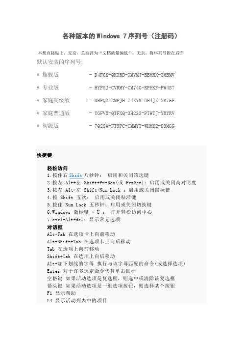
各种版本的Windows 7序列号(注册码)本想直接贴上,无奈,总被评为“文档质量偏低”;无奈,将序列号附在后面默认安装的序列号:* 旗舰版 - D4F6K-QK3RD-TMVMJ-BBMRX-3MBMV* 专业版 - HYF8J-CVRMY-CM74G-RPHKF-PW487* 家庭高级版 - RHPQ2-RMFJH-74XYM-BH4JX-XM76F* 家庭普通版 - YGFVB-QTFXQ-3H233-PTWTJ-YRYRV* 初级版 - 7Q28W-FT9PC-CMMYT-WHMY2-89M6G快捷键轻松访问1.按住右Shift八秒钟:启用和关闭筛选键2.按左 Alt+左 Shift+PrtScn(或 PrtScn):启用或关闭高对比度3.按左 Alt+左 Shift+Num Lock :启用或关闭鼠标键4.按 Shift 五次:启用或关闭粘滞键5.按住 Num Lock 五秒钟:启用或关闭切换键6.Windows 徽标键 + U :打开轻松访问中心7.ctrl+Alt+del:显示常见选项对话框Alt+Tab 在选项卡上向前移动Alt+Shift+Tab 在选项卡上向后移动Tab 在选项上向前移动Shift+Tab 在选项上向后移动Alt+加下划线的字母执行与该字母匹配的命令(或选择选项) Enter 对于许多选定命令代替单击鼠标空格键如果活动选项是复选框,则选中或清除该复选框箭头键如果活动选项是一组选项按钮,则选择某个按钮F1 显示帮助F4 显示活动列表中的项目Backspace 如果在“另存为”或“打开”对话框中选中了某个文件夹,则打开上一级文件夹Windows 徽标键Windows徽标键就是显示为Windows旗帜,或标有文字Win或Windows 的按键,以下简称Win键。
1.Windows 徽标键——打开或关闭「开始」菜单。
2.Windows 徽标键 + Pause——显示“系统属性”对话框。
基尔斯特 9329A … 9389A 型力矩转换器说明书
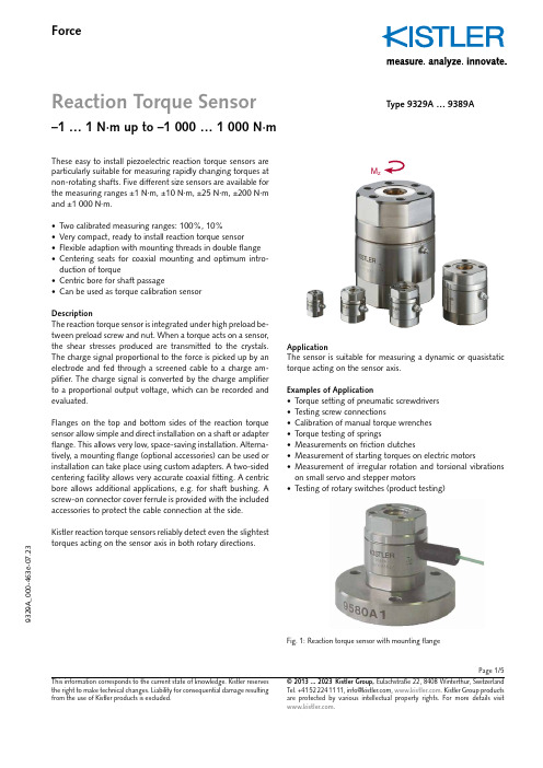
Page 1/5ForceReaction Torque Sensor–1 … 1 N·m up to –1 000 … 1 000 N·m9329A _000-463e -07.23© 2013 ... 2023 Kistler Group, Eulachstraße 22, 8408 Winterthur, Switzerland . Kistler Group products This information corresponds to the current state of knowledge. Kistler reserves the right to make technical changes. Liability for consequential damage resulting Type 9329A … 9389AThese easy to install piezoelectric reaction torque sensors are particularly suitable for measuring rapidly changing torques at non-rotating shafts. Five different size sensors are available for the measuring ranges ±1 N·m, ±10 N·m, ±25 N·m, ±200 N·m and ±1 000 N·m.• Two calibrated measuring ranges: 100%, 10%• Very compact, ready to install reaction torque sensor• Flexible adaption with mounting threads in double flange • Centering seats for coaxial mounting and optimum intro-duction of torque• Centric bore for shaft passage• Can be used as torque calibration sensorDescriptionThe reaction torque sensor is integrated under high preload be-tween preload screw and nut. When a torque acts on a s ensor, the shear stresses produced are transmitted to the c rystals. The charge signal proportional to the force is picked up by an electrode and fed through a screened cable to a charge am-plifier. The charge signal is converted by the charge amplifier to a proportional output voltage, which can be r ecorded and evaluated.Flanges on the top and bottom sides of the reaction torque sensor allow simple and direct installation on a shaft or adapter flange. This allows very low, space-saving installation. Alterna-tively, a mounting flange (optional accessories) can be used or installation can take place using custom adapters. A two-sided centering facility allows very accurate coaxial fitting. A centric bore allows additional applications, e.g. for shaft bushing. A screw-on connector cover ferrule is provided with the included accessories to protect the cable connection at the side. Kistler reaction torque sensors reliably detect even the slightesttorques acting on the sensor axis in both rotary directions.M zApplicationThe sensor is suitable for measuring a dynamic or quasistatic torque acting on the sensor axis.Examples of Application• Torque setting of pneumatic screwdrivers • Testing screw connections• Calibration of manual torque wrenches • Torque testing of springs• Measurements on friction clutches• Measurement of starting torques on electric motors• Measurement of irregular rotation and torsional vibrations on small servo and stepper motors•Testing of rotary switches (product testing)Fig. 1: Reaction torque sensor with mounting flangePage 2/59329A _000-463e -07.23© 2013 ... 2023 Kistler Group, Eulachstraße 22, 8408 Winterthur, Switzerland Tel.+41522241111,****************,. Kistler Group products This information corresponds to the current state of knowledge. Kistler reserves the right to make technical changes. Liability for consequential damage resulting Dimensions Reaction Torque Sensor Type 9329A … 9389ADimensions in mmType D D1D2D3*D4 H A B C E F G K T S x y 9329A20146419.51726313.37.427.4–36M36 2.50.20.19339A 302110828.52634416.610.240.23643.5M48 2.50.30.129349A 3626141134.53242521.710.246.23946.5M59 2.50.350.159369A 54402117534860832.510.464.44856M813 2.50.50.159389A100703023.598901301468.710.7110.770.780.5M12303––* Free access with mounted centering ringsFig. 3: Type 9329AFig. 2: Type 9339A … 9369A with connector protection Fig. 4: Type 9389A with connector protectionConnecting cableConnecting cableConnector protectionPage 3/59329A _000-463e -07.23© 2013 ... 2023 Kistler Group, Eulachstraße 22, 8408 Winterthur, Switzerland Tel.+41522241111,****************,. Kistler Group products This information corresponds to the current state of knowledge. Kistler reserves the right to make technical changes. Liability for consequential damage resulting Technical dataReaction Torque Sensor Type9329A 9339A 9349A 9369A 9389AMeasuring range M z N·m –1 … 1 –10 … 10 –25 … 25 –200 … 200 –1 000 … 1 000Overload M z N·m –1.2/1.2 –12/12 –30/30 –240/240 –1 200 … 1 200Calibrated measuring ranges M z N·m –1 … 1 –10 … 10 –25 … 25 –100 … 100 –1 000 … 1 000M z N·m –0.1 … 0.1 –1 … 1 –2.5 … 2.5 –20 … 20 –100 … 100Threshold M z mN·m <0.03 <0.18 <0.35 <0.62 <0.78Sensitivity pC/N·m ≈–2 170 ≈–460 ≈–230 ≈–130 ≈–100Linearity, all measuring ranges %FSO ≤±0.2 ≤±0.2 ≤±0.2 ≤±0.2 ≤±0.2Hysteresis, all measuring ranges %FSO ≤0.3 ≤0.3 ≤0.3 ≤0.3 ≤0.3Tensile/compression force, max.F z kN –3/9 –5/14 –10/8 –10/10 –60/60Crosstalk F z → M zmN·m/N ≤±0.01 ≤±0.05 ≤±0.01 ≤±0.02 ≤±0.01Side force, max. 1)F x,y kN 0.47 0.38 0.44 0.27 3.66 (M z = 100%; F z = 0)Crosstalk (typical) F x,y → M z mN·m/N <0.5 <0.3 <0.3 <0.3 <0.2Bending moment, max. M x,y N·m 17.3 20 30 27 698 (M z = 100%; F z = 0) Crosstalk M x,y → M z mN·m/N·m <8<8<8<12<10Rigidity c ϕ (M z )mN·m/μrad ≈17 ≈96 ≈189 ≈924 ≈1 540Natural frequency (torsion) f n kHz >53 >36 >33 >23 >11Operating temperature range °C –20 … 80 –40 … 120 –40 … 120 –40 … 120 –40 … 120Temperature coefficient %/°C 0.02 – 0.02 – 0.02 – 0.02 – 0.02 of sensitivityInsulation resistance at 20 °CΩ >1013 >1013 >1013 >1013 >1013Capacitance pF ≈73 ≈43 ≈340 ≈350 ≈910Connection KIAG 10-32 neg.Connector protectorno yes yes yes yes Degree of protection (with cable connected) EN60529 IP65 Case material DIN 1.4542 Weightg 50 137 243 800 6 7201)Application of force in plane of flangeGeneralThe torque should be introduced by the smallest possiblee ccentricity of the axes to be connected (<0.02 mm). Bending moment and shear forces should be avoided as far as p ossible.The surfaces contacting the reaction torque sensor must be flat, rigid and clean. The centering facility on both sides of the reaction torque sensor using centering rings (included acces-sories) allow very accurate coaxial fitting.The sensor can be fitted directly via the integral flanges on two sides. Special adapters can be manufactured for adaptation to the customer's specific applications.Page 4/59329A _000-463e -07.23© 2013 ... 2023 Kistler Group, Eulachstraße 22, 8408 Winterthur, Switzerland Tel.+41522241111,****************,. Kistler Group products This information corresponds to the current state of knowledge. Kistler reserves the right to make technical changes. Liability for consequential damage resulting Adaption A: Installation in Shaft with Adapter for Shaft Journal with PinCustomized tool adapterAdapter for toolshank with pin Pinned during installationPinned during installation Adaption B: Installation in Shaft with Adapter FlangeAdapter flange for flat mounting in shaftCustomizedcentering ring (g6)Customizedcentering ring (g6)Adaption C: Installation with Shaft with Integrated FlangeCentering pin g6 on customized shaftAdapter for cylinder bore recess with pin Adaption D: Adapter Flange for Wrenches with External Square HeadOverview of Installation VariantsM zCentering rings(incl. accessories)Mounting flange Type 9580A…(optional accessories)M zM zPage 5/59329A _000-463e -07.23© 2013 ... 2023 Kistler Group, Eulachstraße 22, 8408 Winterthur, Switzerland Tel.+41522241111,****************,. Kistler Group products This information corresponds to the current state of knowledge. Kistler reserves the right to make technical changes. Liability for consequential damage resulting Adaption E: Screw Plate with Spring AssemblySpring assemblyCustomizedscrew plate Adaption F: Desktop Installation with Mounting FlangeOrderinkey T ype Scope of delivery including accessories Reaction Torque Sensor 9329A • 2 x Centering ring 3.420.196Reaction Torque Sensor 9339A • Connector protection 3.414.366• 2 x Centering ring 3.420.179Reaction Torque Sensor 9349A • Connector protection 3.414.366• 2 x Centering ring 3.420.180Reaction Torque Sensor 9369A • Connector protection 3.414.366• 2 x Centering ring 3.420.181Reaction Torque Sensor 9389A • Connector protection 3.414.366• 2 x Centering ring3.420.197Optional accessories Type• Connecting cable(see data sheet 1631C_000-346)• Mounting flange9580A…for ype ype D1 d d1 d2 d3 d4 d5 d6 H2 T 1 N 9329A 9580A9 14 40 30 6 4.5 3.2 4.5 5.6 8 2 39339A 9580A0 21 62 50 10 5.5 4.3 8.5 7.5 11 2 59349A 9580A1 26 70 55 14 6.6 5.3 12 9 13 2 69369A 9580A2 40 100 78 21 13.5 8.4 18 14 22 2 99389A 9580A4 70 180 135 30 17 13 25 20 30 2.5 13Mounting flangeCentering rings (incl. accessories)Centering rings (incl. accessories)Mounting flange (optional accessories)M zFig. 5: Type 9580A9 ... A2Fig. 6: Type 9580A4。
7279数据手册

入电流时,其它引脚则不吸入电流。XX7299可以直接驱动0.5英寸至2英寸的共阴数码管,8×8
矩阵的发光二级管LED阵列或者64个独立发光管。
实际电路段选要20k下拉后接200欧姆电阻(调整该电阻值可以改 变亮度,5V供电时,阻
值范围在100~270欧姆之间)再到数码管段选和按键。随芯片供电电压的减小可以再减小段限 流电阻来保证亮度,当芯片3.3V供电时可以去掉该电阻。位选直接接到数码管位选,但是位选
a
- ->256 字节 SRAM,共 4 页,每页 64 字节;
->RTC(0000~9999 年阳历及星期,阴历 2000~2099 年阴历算法,2000~2099 年节气算法,
a 注意需要外加 32768Hz 晶振作为 RTC 时钟)和秒中断输出; ->芯片可设定工作在睡眠状态,睡眠时芯片停止工作,显示等都被关闭,但是当有两线通
.
“8 数码管+64 按键+RTC+E2PROM+SRAM+CPU 监控”管理芯片
m
r ——基于两线通信接口(兼容 I2C)
a
-
XX7279 数据手册a
g
p 海纳电子资讯网:www.fpga-arm.com 为
w
w
w
枭潇
海纳电子资讯网:www.fpga-arm.com 为您提供各种IC中文资料
m
r 5、32 脚贴片封装还提供两路 8 位 ADC,并且是经过了低通滤波的 ADC 采样值;
6、XX7299 的控制和状态查询全部都是通过读/写寄存器实现的,用户只需象读写 24C02
内的单元一样即可实现对 XX7299 的控制; 7、同样的价格。
a
三、XX7299 引脚说明
1N4148W-7-F中文资料

Maximum Ratings @TA = 25°C unless otherwise specified
Characteristic
Peak Repetitive Reverse Voltage Working Peak Reverse Voltage DC Blocking Voltage
RMS Reverse Voltage
Characteristic Reverse Breakdown Voltage (Note 3)
Symbol
Min
V(BR)R
100
Forward Voltage
VFM
⎯
Peak Reverse Current (Note 3) Total Capacitance Reverse Recovery Time
Operating and Storage Temperature Range
A B
Symbol VRRM VRWM VR
VR(RMS) IFM IO IFSM Pd RθJA
Tj, TSTG
D G
E
Value 100 71 300 150 2.0 1.0 400 315
-65 to +150
Notes:
Marking Information
Shipping 3000/Tape & Reel 3000/Tape & Reel
XX = Product Type Marking Code (See Page 1)
YM
XX
YM = Date Code Marking Y = Year ex: N = 2002
Unit
V
V mA mA A mW °C/W °C
W8209_6208E量产工具 Flash支持列表
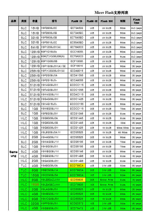
2CE 4CE 1CE 1CE 2CE 1CE 1CE 2CE 4CE 1CE 2CE 4CE 1CE 1CE 2CE 1CE 1CE 1CE 1CE 1CE 1CE 1CE 1CE 1CE 1CE 1CE 2CE 1CE 1CE 2CE 1CE 2CE 2CE 1CE 2CE 4CE
HY27UG088G5M HY27UH088G2M HY27UG088G2M HY27UH08AG5M
1b\512B 1b\512B 1b\512B 1b\512B 1b\512B 1b\512B 1b\512B 1b\512B 4b\512B 4b\512B 4b\512B 4b\512B
90nm 70nm 70nm 70nm 60nm 60nm 57nm 57nm 90nm 60nm 60nm 60nm
MLC 512MB HY27UU(T)084G2M MLC 512MB HY27UT084G2A SLC SLC SLC SLC SLC SLC SLC SLC HYNI X SLC MLC MLC MLC MLC 512MB HY27UF084G2MW 512MB HY27UG(H)084G2A 512MB HY27UF(G)084G2M 1GB 1GB 1GB 2GB 1GB 1GB 1GB 2GB 4GB
16GB K9HDG08U5M
K9G8G08U0C K9GAG08U0E K9LBG08U0E K9GAG08U0M1 K9GAG08U0D K9HBG08U1A K9MBG08U5M K9LBG08U0M K9HCG08U1M
16GB K9MDG08U5M
K9AAG08U0M K9ABG08U0M
HY27UV08AG5M H27UAG8T2ATR H27UBG8T2ATR H27UCG8VFMTR H27UBG8U5MTR H27UAG8T2MTR HY27UW08BGFM H27UBG8T2ATR H27UCG8U5ATR
FPGA可编程逻辑器件芯片XCZU7EV-1FBVB900I中文规格书
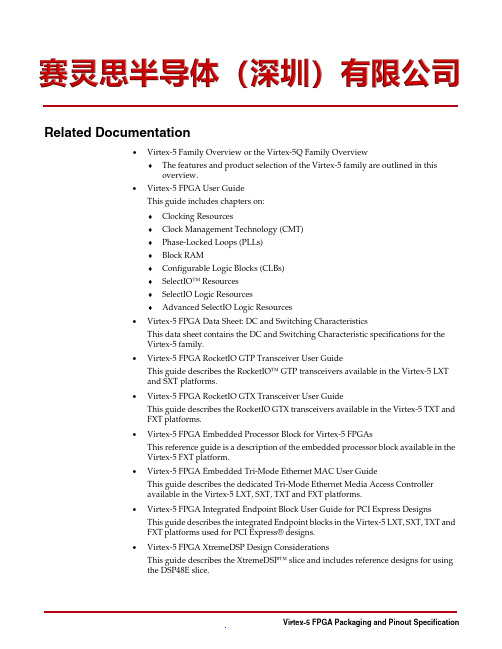
Related Documentation•Virtex-5 Family Overview or the Virtex-5Q Family Overview♦The features and product selection of the Virtex-5 family are outlined in thisoverview.•Virtex-5 FPGA User GuideThis guide includes chapters on:♦Clocking Resources♦Clock Management Technology (CMT)♦Phase-Locked Loops (PLLs)♦Block RAM♦Configurable Logic Blocks (CLBs)♦SelectIO™ Resources♦SelectIO Logic Resources♦Advanced SelectIO Logic Resources•Virtex-5 FPGA Data Sheet: DC and Switching CharacteristicsThis data sheet contains the DC and Switching Characteristic specifications for theVirtex-5 family.•Virtex-5 FPGA RocketIO GTP Transceiver User GuideThis guide describes the RocketIO™ GTP transceivers available in the Virtex-5 LXTand SXT platforms.•Virtex-5 FPGA RocketIO GTX Transceiver User GuideThis guide describes the RocketIO GTX transceivers available in the Virtex-5 TXT andFXT platforms.•Virtex-5 FPGA Embedded Processor Block for Virtex-5 FPGAsThis reference guide is a description of the embedded processor block available in theVirtex-5 FXT platform.•Virtex-5 FPGA Embedded Tri-Mode Ethernet MAC User GuideThis guide describes the dedicated Tri-Mode Ethernet Media Access Controlleravailable in the Virtex-5 LXT, SXT, TXT and FXT platforms.•Virtex-5 FPGA Integrated Endpoint Block User Guide for PCI Express DesignsThis guide describes the integrated Endpoint blocks in the Virtex-5 LXT, SXT, TXT andFXT platforms used for PCI Express® designs.•Virtex-5 FPGA XtremeDSP Design ConsiderationsThis guide describes the XtremeDSP™ slice and includes reference designs for usingthe DSP48E slice.FF1136 Package—LX50T, FX70T, LX85T, LX110T, LX155T, SX50T, SX95T, and FX100T6IO_L5N_6 AK14LX50T, LX85T, SX50T 6IO_L6P_6 AK23LX50T, LX85T, SX50T 6IO_L6N_6 AK22LX50T, LX85T, SX50T 6IO_L7P_6 AL15LX50T, LX85T, SX50T 6IO_L7N_6 AL14LX50T, LX85T, SX50T 6IO_L8P_CC_6 AJ21LX50T, LX85T, SX50T 6IO_L8N_CC_6(2)AJ20LX50T, LX85T, SX50T 6IO_L9P_CC_6 AJ16LX50T, LX85T, SX50T 6IO_L9N_CC_6(2)AJ15LX50T, LX85T, SX50T 6IO_L10P_CC_6 AK16LX50T, LX85T, SX50T 6IO_L10N_CC_6(2)AL16LX50T, LX85T, SX50T 6IO_L11P_CC_6 AL21LX50T, LX85T, SX50T 6IO_L11N_CC_6(2)AK21LX50T, LX85T, SX50TTable 2-5:FF1136 Package—LX50T, FX70T, LX85T, LX110T, LX155T, SX50T, SX95T and FX100T (Continued)Bank Pin DescriptionPin NumberNo Connect (NC)Chapter 2:Pinout TablesTable 2-5:FF1136 Package—LX50T, FX70T, LX85T, LX110T, LX155T, SX50T, SX95Tand FX100T (Continued)Bank Pin Description Pin Number No Connect (NC)15IO_L5N_15 G3115IO_L6P_15 J3015IO_L6N_15 J3115IO_L7P_15 L3015IO_L7N_15 M3015IO_L8P_CC_15 N2915IO_L8N_CC_15(2)P2915IO_L9P_CC_15 K3115IO_L9N_CC_15(2)L3115IO_L10P_CC_15 P3115IO_L10N_CC_15(2)P3015IO_L11P_CC_15 M3115IO_L11N_CC_15(2)N3015IO_L12P_VRN_15 R2815IO_L12N_VRP_15 R2915IO_L13P_15 T3115IO_L13N_15 R3115IO_L14P_15 U3015IO_L14N_VREF_15 T3015IO_L15P_15 T2815IO_L15N_15 T2915IO_L16P_15 U2715IO_L16N_15 U2815IO_L17P_15 R2615IO_L17N_15 R2715IO_L18P_15 U2615IO_L18N_15 T2615IO_L19P_15 U2515IO_L19N_15 T2517IO_L0P_17 W2417IO_L0N_17 V2417IO_L1P_17 Y26FF1136 Package—LX50T, FX70T, LX85T, LX110T, LX155T, SX50T, SX95T, and FX100T Table 2-5:FF1136 Package—LX50T, FX70T, LX85T, LX110T, LX155T, SX50T, SX95T and FX100T (Continued)Bank Pin Description Pin Number No Connect (NC)17IO_L1N_17 W2617IO_L2P_17 V2517IO_L2N_17 W2517IO_L3P_17 Y2717IO_L3N_17 W2717IO_L4P_17 V3017IO_L4N_VREF_17 W3017IO_L5P_17 V2817IO_L5N_17 V2717IO_L6P_17 W3117IO_L6N_17 Y3117IO_L7P_17 W2917IO_L7N_17 V2917IO_L8P_CC_17 Y2817IO_L8N_CC_17(2)Y2917IO_L9P_CC_17 AB3117IO_L9N_CC_17(2)AA3117IO_L10P_CC_17 AB3017IO_L10N_CC_17(2)AC3017IO_L11P_CC_17 AA2917IO_L11N_CC_17(2)AA3017IO_L12P_VRN_17 AD3117IO_L12N_VRP_17 AE3117IO_L13P_17 AD3017IO_L13N_17 AC2917IO_L14P_17 AF3117IO_L14N_VREF_17 AG3117IO_L15P_17 AE2917IO_L15N_17 AD2917IO_L16P_17 AJ3117IO_L16N_17 AK3117IO_L17P_17 AF29Chapter 3:Pinout and SelectIO Bank DiagramsFF1738 Package—FX100T, LX110T, LX155T, and LX220TFigure 3-21:FF1738 Package—FX100T, LX110T, LX155T, and LX220T Pinout Diagram。
电子芯片大全
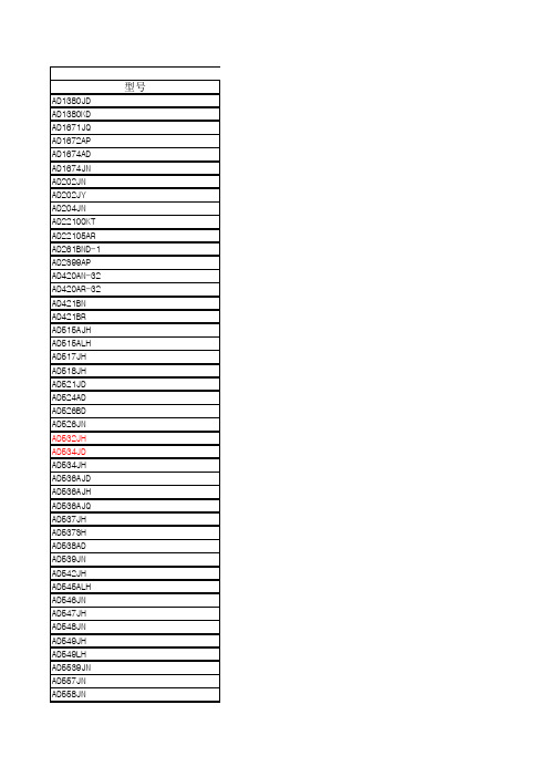
号功能简述型号AD1380JDAD1380KDAD1671JQAD1672APAD1674ADAD1674JNAD202JNAD202JYAD204JNAD22100KTAD22105ARAD261BND-1AD2S99APAD420AN-32AD420AR-32AD421BNAD421BRAD515AJHAD515ALHAD517JHAD518JHAD521JDAD524ADAD526BDAD526JNAD532JHAD534JDAD534JHAD536AJDAD536AJHAD536AJQAD537JHAD537SHAD538ADAD539JNAD542JHAD545ALHAD546JNAD547JHAD548JNAD549JHAD549LHAD5539JNAD557JNAD558JNAD568JQ AD569JN AD570JD/+ AD574AJD AD574AKD AD578KN AD580JH AD580LH AD581JH AD582KD AD584JH AD584JN AD585AQ AD586JN AD586JQ AD586KN AD586KQ AD586KR AD587KN AD587KR AD588AQ AD589JH AD590JH AD590KH AD592AN AD592BN AD595AD AD595AQ AD598AD AD600XN AD602JN AD603AQ AD606JN AD607ARS AD620AN AD621AN AD622AN AD623AN AD623AR AD624AD AD625JN AD625KN AD626AN AD627AN AD629AN AD630JNAD636JDAD636JHAD637JQAD648JNAD650JNAD650KNAD652AQAD654JNAD654JRAD660ANAD6640AST AD6644AST AD667JNAD667KNAD669ANAD670JNAD676JDAD676JNAD676KDAD677ARAD677JDAD677JNAD678JDAD678KNAD679JNAD679KNAD680JNAD684JQAD693AQAD694AQAD694JNAD698APAD7008AP20 AD7008JP-50 AD704JNAD705JNAD706JNAD707AQAD707JNAD708AQAD708JNAD7111ABN AD7111LN AD711AQAD711JNAD711JRAD712JN AD713BQ AD713JN AD720JP AD7224KN AD7226KN AD7228ABN AD722JR-16 AD7237AAN AD7237JN AD7243AN AD7245AAN AD7249BN AD724JR AD73360AR AD734AQ AD736JN AD737AQ AD737JN AD7416AR AD741KN AD743JN AD744JN AD745JN AD75019JP AD7501JN AD7502JN AD7502KQ AD7503JN AD7506JN AD7507JN AD7510DIJN AD7510DIKN AD7512DIJN AD7512DIKN AD7520LN AD7523JN AD7524JN AD7528JN AD7528KN AD7533JN AD7535JN AD7537JN AD7541AKN AD7542JN AD7543KNAD7564BN AD7574JN AD7590DIKN AD7660AST AD7664AST AD767JNAD768ARAD7701AN AD7703AN AD7703BN AD7705BN AD7705BR AD7706BN AD7707BR AD7710AN AD7711AN AD7712AN AD7713AN AD7714AN-3 AD7714AN-5 AD7715AN-5 AD7715AR-5 AD7731BN AD7741BN AD7742BN AD7750AN AD7755AARS AD7777AR AD779JDAD780ANAD781JNAD7820KN AD7821KN AD7822BN AD7824BQ AD7824KN AD7837AN AD7845JN AD7846JN AD7847AN AD7856AN AD7862AN-10 AD7864AS-1 AD7865AS-1 AD7872AN AD7874ANAD7886JD AD7886KD AD7888AR AD7890AN-10 AD7891AP-1 AD7892AN-1 AD7895AN-10 AD790JNAD795JNAD797ANAD797ARAD8001AN AD8002AN AD8009AR AD8011AN AD8015AR AD8018AR AD8031AN AD8032AN AD8036AN AD8037AN AD8041AN AD8041AR AD8042AN AD8044AN AD8047AN AD8055AR AD8056AR AD8058AR AD8079AR AD8108AST AD8109AST AD810ANAD8111AST AD8115AST AD8116AST AD811ANAD811JRAD812ANAD812ARAD8131AR AD8138AR AD813ANAD813AR-14 AD815AYAD8170ANAD817ANAD8180AN AD8184AN AD818ANAD820ANAD822ANAD822AN-3V AD823ANAD824ANAD826ANAD827AQAD827JNAD828ANAD829JNAD8307AN AD8307AR AD8309ARU AD830ANAD830ANAD8313ARM AD8313ARM AD8320ARP AD834JNAD8350AR15 AD835ANAD8402AN-10 AD8403AN100 AD840JNAD843AQAD844ANAD845JNAD845KNAD847AQAD847JNAD847SQAD849JNAD8522AN AD8551AR AD8552AR AD8561AN AD8561AR AD8564AN AD8598AN AD9042AST AD9048JQ AD9049BRSAD9051BRSAD9057BRS-40 AD9057BRS-60 AD9058JJAD9059BRSAD9066JRAD9071BRAD9101ARAD9200ARSAD9203ARUAD9220ARAD9221ARAD9223ARAD9225ARAD9226ARSAD9240ASAD9243ASAD9260ASAD9280ARSAD9281ARSAD9283BRS-100 AD9283BRS-80 AD9288BRS-80 AD9300KQAD9483KS-100 AD9500BQAD9501JNAD9617JRAD9617JNAD9618JNAD9630ANAD9631ANAD96687BQAD9698KNAD9708ARUAD9709ASTAD9713BANAD9721BRAD9731BRAD9732BRSAD9750ARAD9752ARAD9760ARAD9762ARAD9764ARAD976CNAD976AAN AD9772AST AD977AAN AD977AN AD9801JCST AD9802JST AD9803JST AD9805JS AD9816JS AD9822JR AD9830AST AD9831AST AD9832BRU AD9850BRS AD9851BRS AD9852AST AD9852ASQ AD9853AS AD9854AST AD9854ASQ AD9901KQ ADG201AKN ADG201HSJN ADG211AKN ADG222AKN ADG333ABN ADG333ABR ADG408BN ADG409BN ADG411BN ADG417BN ADG419BN ADG431BN ADG436BN ADG441BN ADG442BN ADG506AKN ADG507AKN ADG508AKN ADG508FBN ADG509AKN ADG511BN ADG608BN ADG609BN ADG719BRM ADG736BRMADM690ANADM708ANADSP21060KS160 ADSP21060CZ-160 ADSP21062KS-160 ADSP2181KS-133 ADSP2181KST-133 ADUC812BS ADVF32KNADXL105JQC ADXL202AQC AMP02FPAMP04FPDAC08CPDAC8228FPOP07AZ/883COP07CPOP07CSOP176GPOP177GPOP27GPOP291GPOP295GPOP296GPOP297GPOP297GSOP37EPOP37GPOP495GPOP497GPOP77GPOP90GPOP97FPOP97FSPKD01FPREF02CPREF03GPREF192GPREF192GSREF194GPREF195GSREF43FZSMP04EPSMP08FPSSM2141PSSM2142PSSM2211P SSM2275P TMP03FS TMP04FS TMP36GT9 MAX038CPP MAX1044CPA MAX110ACPE MAX110BCPE MAX111BCPE MAX122BCNG MAX1232CPA MAX1242BCSA MAX125CEAX MAX134CPL MAX135CPI MAX139CPL MAX140CPL MAX1480BCPI MAX1480BEPI MAX1483CPA MAX1487CPA MAX1487ECPA MAX1488ECPD MAX1489ECPD MAX148BCPP MAX1490BCPG MAX158BCPI MAX1771CPA MAX1771CSA MAX180CCPL MAX186CCPP MAX187BCPA MAX189CCPA MAX191BCNG MAX192BCPP MAX197BCNI MAX202CPE MAX202CSE MAX202ECPE MAX202EESE MAX202EPE MAX207CNG MAX208CNG MAX232CPE MAX232CSEMAX235CPG MAX238CNG MAX238ENG MAX260BCHG MAX260BENG MAX261BCNG MAX280CPA MAX291CPA MAX292CPA MAX293CPA MAX294CPA MAX297CPA MAX301CPE MAX305EPE MAX306CPI MAX3080CPD MAX3082CPA MAX308CPE MAX309CPE MAX3100CPD MAX312CPE MAX313CPE MAX318CPA MAX319CPA MAX3218CPP MAX3223CPP MAX3232CPE MAX325CPA MAX333CPP MAX338CPE MAX339CPE MAX351CPE MAX354CPE MAX354CWE MAX354EPE MAX355CPE MAX355CWE MAX366CPA MAX367CPN MAX384CPN MAX391CPE MAX400CPA MAX4016ESA MAX4100ESA MAX4101ESA MAX4106ESAMAX4142ESD MAX4146ESD MAX419CPD MAX420CPA MAX427CPA MAX435CPD MAX436CPD MAX440CPI MAX441CPP MAX442CPA MAX4456CPL MAX453EPA MAX457EPA MAX458CPL MAX468CPE MAX470CPE MAX479CPD MAX480EPA MAX483CPA MAX485CPA MAX487CPA MAX487ECPA MAX487EEPA MAX488CPA MAX490ECPA MAX491CPD MAX491ECPD MAX501AENG MAX504CPD MAX505BCNG MAX506CPP MAX509BCPE MAX512CPD MAX515CPA MAX517BCPA MAX518BCPA MAX526DCNG MAX527DCNG MAX528CPP MAX530BCNG MAX531BCPD MAX532BCPE MAX536BCWE MAX538BCPA MAX543ACPA MAX551ACPAMAX619CPA MAX6225ACPA MAX6225AESA MAX6225BCPA MAX6225BCSA MAX622CPA MAX6250BCPA MAX633ACPA MAX638AEPA MAX639CPA MAX660CPA MAX662ACPA MAX667CPA MAX691ACPE MAX691CPE MAX705CPA MAX706CPA MAX708CPA MAX708CSA-T MAX709LEPA MAX712CPE MAX712EPE MAX713CPE MAX7219CNG MAX7219ENG MAX724CCK MAX726CCK MAX729CCK MAX730ACPA MAX733CPA MAX735CPA MAX736CPD MAX738ACPA MAX738AEPA MAX739CPD MAX739CWE MAX7400CPA MAX743CPE MAX743EPE MAX749CPA MAX750ACPA MAX756CPA MAX761CPA MAX764CPA MAX765CPA MAX766EPAMAX791CPE MAX807LCPE MAX810LEUR-T MAX813LCPA MAX813LEPA MAX818LCPA MAX860ISA MAX865EUA MAX866ESA MAX874EPA MAX875BCPA MAX882CPA MAX883CPA MAX883CSA MAX907CPA MAX910CNG MAX912CPE MAX913CPA MAX931CPA MAX934CPE MXD1210CPA LFC2LFC3LFC4LFC54LFC75F003F004(5G23)F005F006F007(5G24)F010F011F1550F1490F1590F157/AF253F741(F007)F741AF747OP-07OP111AF4741F101A/201AF301AF308F110/210 F310F118/218 F441F318F124/224 F324F148F248/348 F158/258 F358F1558F4558LF791LF4136 FD37/FD38 FD46LF082 LFOP37LF3140LF7650LZ1606LZ19001 LBMZ1901 LM741LM747OP-07LM101/201 LM301LM108/208 LM308LM110LM310LM118/218 LM318LM124/224 LM324LM148LM248/348 LM158/258 LM358LM1558 OP-27CP TL062TL072TL082TL084MC1458LF147/347LF156/256/356LF107/307LF351LF353LF155/355LF157/357LM359LM381CA3080CA3100CA3130CA3140CA3240CA3193CA3401MC3303MC3403LF411LF444µpc4558MC4741LM709LM725LM733LM748ICL7650ICL7660稳压器固定输出(正电压)稳压器78xx 系列 3端稳压器 5V 到 24V1A78Lxx 系列 3端稳压器 5V 到 24V 0.1A78Mxx 系列 3端稳压器 5V 到 24V 0.5A78Sxx 系列 3端稳压器 5V 到 24V 2A固定输出(负电压)稳压器79xx 系列 3端负电压稳压器 -5V 到 -24V 1A [110kb] 79Lxx 系列 3端负电压稳压器 -5V 到 -24V 0.1A [95kb]可调输出 - 常用稳压器LM117 1.2V... 37V 1.5A 正电压可调稳压器 [100kb] LM217 1.2V... 37V 1.5A 正电压可调稳压器 [100kb] LM317 1.2V... 37V 1.5A 正电压可调稳压器 [100kb] LM137 -1.2V...-37V 1.5A 负电压可调稳压器 [246kb] LM237 -1.2V...-37V 1.5A 负电压可调稳压器 [246kb]LM337 -1.2V...-37V 1.5A 负电压可调稳压器 [246kb] LM138 1.2V --32V 5-安培 可调LM338 1.2V -- 32V 5-安培 可调LM723 高精度可调 [136kb]L200 2 A / 2.85 to 36 V.可调 [166KB]TTL 逻辑电路 [LS - HC 或 HCT 系列]74LS0074LS0474LS0874LS1074LS1374LS1474LS2774LS3074LS3274LS4274LS4574LS4774LS9074LS9274LS9374LS12174LS15474LS19274LS19374HC23774LS37474LS390CMOS 逻辑电路4001400240074011401340164017402240234025402640284029404040464051405240534055 4056 4060 4066 4067 4068 4069 4071 4072 4075 4081 4082 4093 4511 4518 4583 4584晶体管小功率管2N9302N16132N2222A 2N34392N34402N39042N39062N54012N54152N54162N55502N55512N65152N49212N49222N4923 AF125 BC107 BC108 BC109 BC148 BC177 BC178 BC179 BC182 BC183 BC184BC214BC327BC301BC302BC303BC304BC328BC337BC338BC414BC416BC461BC516BC517BC546BC547BC548BC549BC550BC556BC557BC558BC559BC560BC635BC636BC637BC638BC639BC640BCY70BCY71BCY78BCY79BCY87BCY88BCY89MPSL01 MPSL51 MPSA06 MPSA42 MPSA43 MPSA56 MPSA92 MPSA93中、大功率管2N6283 2N6284 2N6286 2N6287 BD135 BD136 BD137 BD138 BD139 BD140 BD162 BD203 BD204 BD241C BD242C BD243 BD249 BD250 BD375 BD376 BD377 BD378 BD379 BD380 BD543 BD529 BD530 BD533 BD534 BD535 BD536 BD537 BD538 BD677 BD678 BD679 BD680 BD681 BD682 BD591 BD592 BDX53C BDX54C BDW51 BU208A BU508AMJ2955MJ4502MJ15003MJ15004MJE340MJE350MJE15028MJE15029MJE15030MJE15031PMD16K100PMD17K100TIP31TIP32TIP122TIP140TIP141TIP142TIP145TIP146TIP147TIP2955TIP3055Fet 晶体管2N52482N54572N5460BS170BF245CBF256BJ210J211J212Fet 功率管2SK15302SJ201IRF540IRF9540集成电路(模拟)AD711CA3130LH0032LF351LF411LM108LM208LM833LM358LM359LM324LM391LM393NE5532NE5534OP27OP37TL071TL072TL074TL081TL082TL084TLC271TLC272TLC274MN3004IC's 功率放大 [模拟] L165LM388LM1875TDA1516BQTDA1519CTDA1563QTDA2002TDA2005TDA2004TDA2030STK4036 IISTK4036 XISTK4038 IISTK4040 IISTK4040 XISTK4042 IISTK4042 XISTK4044 IISTK4044 IISTK4046 XISTK4048 XISTK4050 V显示驱动LM3914LM3915UAA180CA3161ECA3162EICL7136PLL 立体声解码LM1800CA3090PMC1310P定时-时钟电路555556MN3101XR2206光电耦合4N254N264N274N284N354N364N37H11A1H11A2H11A3SCR - TRIAC BTY79-800RC106D时钟MM5314N二极管1N4000 系列1N41481N5408IN5236B1N5240B1N5252B电子管300B5U4G6SN76BX76DJ8ECC886N1PECC88692212AT712AU712AX7E80CCECC81ECC82ECC83ECC88EL34EL84Z2CKT88常用锁相环电路集成电路型号(规格) 数据表生产厂家器件名称参考单价兼容型号EM92600/1EMC 专用型锁相环(中国10频道)HT9286A/BHT9287A/BHOLTEK 专用型锁相环(美国10频道)HT9288A/BHOLTEK 专用型锁相环(中国10频道)HYL21011S/JHYUNDAI 通用型锁相环HYL21012S/JHYUNDAI 专用型锁相环(美国10频道)HYL21014S/JHYUNDAI 专用型锁相环(中国10频道)MC145162MOTOROLA通用型锁相环MC145166MOTOROLA专用型锁相环(美国10频道)MC145167MOTOROLA专用型锁相环(美国10频道)KS8805BGM6532LG 专用型锁相环(中国10频道)DMD5603DAEWOO专用型锁相环(中国10频道)DMD5602DAEWOO专用型锁相环(美国10频道)KA567KA567LLM567常用元器件ICL7106,ICL7107DAC0830/DAC0832ADC0831/ADC0832/ADC0834/ADC0838 ADC0808/ADC0809ADC0802/ADC0803/ADC0804AD7520/AD7521/AD7530/AD75214N35/4N36/4N37ICL7116,ICL7117ICL7650ICL7660/MAX1044ICL7106,ICL7107DAC0830/DAC0832ADC0831/ADC0832/ADC0834/ADC0838 ADC0808/ADC0809ADC0802/ADC0803/ADC0804AD7520/AD7521/AD7530/AD75214N35/4N36/4N37ICL7116,ICL7117ICL7650ICL7660/MAX1044ICL8038ICM7216ICM7226ISO2-CMOSLF351LF353LM117/LM317A/LM317LM124/LM124/LM324LM137/LM337LM139/LM239/LM339LM158/LM258/LM358LM193/LM293/LM393LM201/LM301LM231/LM331LM285/LM385LM308ALM386LM399LM431LM567/LM567CLM741LM831LM833LM8365MAX038MC1403MC1404MC1413/MC1416MC145026/MC145027/MC145028MC145403-5/8MC145406MC145407MC145583MC145740MC1488MC1489MC2833MC3362MC4558MC7800系列MC78L00系列MC78M00系列MC78T00系列MC7900系列MC79L00系列MC79M00系列Microchip PIC系列单片机RS232通讯应用MM5369MOC3009/MOC3012MOC3020/MOC3023MOC3081/MOC3082/MOC3083MOC8050MOC8111MT8870MT8888CNE5532/NE5532ANE5534/SE5534NE555/SA555NE556/SA556/SE556NE570/NE571/SA571OP07OP27OP37OP77OP90PC817/PC827/PC847PT2262PT2272SG2524/SG3524ST7537TDA1521TDA7000TTDA7010TTDA7021TTDA7040TTDA7050TL062/TL064TL071/TL072/TL074TL082/TL084 JFETTL494TL594TLP521/1-4TOP100-4TOP221-7TOP232-4TOP412/TOP414ULN2068ULN2803ULN2803/ULN2804VFC32LM319LM393/LM339经典8腿IC封装(LM393)经典14腿IC封装(LM339)电源范围 2――36V静态工作电流 0.4mA翻转时间 1.3us最大输出电流 16mA输入电压范围 -0.3V――Vcc型号功能简述功能16位 20us高性能模数转换器(民用级)16位 20us高性能模数转换器(民用级)12位 1.25MHz采样速率带宽2MHz模数转换器(民用级)12位 3MHz采样速率带宽20MHz单电源模数转换器(工业级)12位 100KHz采样速率带宽500KHz模数转换器(工业级)12位 100KHz采样速率带宽500KHz模数转换器(民用级)小型2KHz隔离放大器(民用级)卧式小型2KHz隔离放大器(民用级)立式小型5KHz隔离放大器(民用级)卧式带信号调理比率输出型温度传感器可编程温控开关电阻可编程温度控制器 SOIC数字隔离放大器可编程正弦波振荡器(工业级) PLCC16位单电源 4-20mA输出数模转换器(工业级)DIP16位单电源 4-20mA输出数模转换器(工业级)SOIC16位环路供电符合HART协议 4-20mA输出数模转换器(工业级)DIP 16位环路供电符合HART协议 4-20mA输出数模转换器(工业级)SOIC 低价格,低偏置电流,高输入阻抗运放(民用级) TO-99低价格,低偏置电流,高输入阻抗运放(民用级) TO-99低失调电压,高性能运放 (民用级) TO-99宽带,低价格运放(民用级) TO-99电阻设置增益精密仪表放大器(民用级)DIP引脚设置增益高精度仪表放大器(工业级)DIP软件编程仪表放大器(工业级)DIP软件编程仪表放大器(民用级)DIP模拟乘法器(民用级)TO-99模拟乘法器(民用级)DIP模拟乘法器(民用级)TO-99集成真有效值直流转换器(民用级)DIP集成真有效值直流转换器(民用级)TO-99集成真有效值直流转换器(民用级)DIP150KHZ集成压频转换器(民用级)TO-99150KHZ集成压频转换器(军用级)TO-99单片实时模拟乘法器(工业级)DIP宽带双通道线性乘法器(民用级)DIP低价格,低偏置电流,高输入阻抗运放(民用级) TO-99低偏置电流,高输入阻抗运放(民用级) TO-99静电计放大器(民用级)DIP低价格,低偏置电流,高输入阻抗运放(民用级) TO-99精密 BiFET输入运放(民用级)DIP低偏置电流,高输入阻抗运放(民用级) TO-99低偏置电流,高输入阻抗运放(民用级) TO-99高速运放(民用级)DIP微处理器兼容完整7位电压输出数模转换器(民用)DIP微处理器兼容完整8位电压输出数模转换器(民用)DIP12位 0.25us电流输出数模转换器(民用)DIP12位超高速电流输出数模转换器(民用)DIP16位 3us电流输出数模转换器(民用)DIP8位 25us模数转换器(民用)DIP12位 25us模数转换器(民用)DIP12位 25us模数转换器(民用)DIP12位 3us模数转换器(民用)DIP精密 2.5V电压基准源(民用级)TO-52精密 2.5V电压基准源(民用级)TO-52精密 10V电压基准源(民用级)TO-50.7us采样保持放大器(民用)DIP引脚设置输出电压基准源(民用级)TO-99引脚设置输出电压基准源(民用级)DIP3us采样保持放大器(工业级)DIP精密 5V电压基准源(民用级)DIP精密 5V电压基准源(民用级)DIP精密 5V电压基准源(民用级)DIP精密 5V电压基准源(民用级)DIP精密 5V电压基准源(民用级)SOIC精密 10V电压基准源(民用级)DIP精密 10V电压基准源(民用级)SOIC精密可编程电压基准源(工业级)DIP精密 1.235V电压基准源(民用级)H-02A—55℃~150℃测温范围温度传感器 TO-52—55℃~150℃测温范围温度传感器 TO-52低价格,精密单片温度传感器 TO-92低价格,精密单片温度传感器 TO-92K型(铬-铝)热电偶信号调节器(工业级)DIPK型(铬-铝)热电偶信号调节器(工业级)DIP线性可变位移信号调节器(LVDT)(工业级)DIP低噪声宽带可变增益双运放(民用级)DIP低噪声宽带可变增益双运放(民用级)DIP低噪声可变增益运放(工业级)DIP50MHz, 80db对数放大器(民用级)DIP低功耗混频器/AGC/RSSC 3V接收机的IF子系统(工业级) SSOP 低功耗仪表放大器(工业级)DIP低功耗仪表放大器(工业级)DIP单电源仪表放大器(工业级)DIP单电源Rail-Rail输出仪表放大器(工业级)DIP单电源Rail-Rail输出仪表放大器(工业级)SOIC精密仪表放大器(工业级)DIP可编程增益仪表放大器(民用级)DIP可编程增益仪表放大器(民用级)DIP单电源仪表放大器(工业级)DIP单电源低功耗Rail-Rail输出仪表放大器(工业级)DIP高电压抑制比差分放大器(工业级) DIP平衡跳制解调器(民用级)DIP低价格模拟乘法器(民用级)DIP高精度真有效值直流转换器(民用级)DIP高精度真有效值直流转换器(民用级)TO-99高精度真有效值直流转换器(民用级)DIP精密,BiFET输入运放(民用级)DIP1MHz,电压频率转换器(民用级)DIP1MHz,电压频率转换器(民用级)DIP2MHz,同步电压频率转换器(工业级)DIP500KHz,低价格电压频率转换器(民用级)DIP500KHz,低价格电压频率转换器(民用级)SOIC16位 8us串并行输入数模转换器(工业级)DIP12位65MSPS模数转换器(工业级) LQFP14位65MSPS模数转换器(工业级) LQFP12位 3us并行输入数模转换器(民用级)DIP12位 3us并行输入数模转换器(民用级)DIP16位 8us并行输入数模转换器(工业级)DIP单电源,内带仪表放大器电压基准源8位数模转换器(民用级)DIP16位100KSPS采样速率并行输出模数转换器(民用级)DIP16位100KSPS采样速率并行输出模数转换器(民用级)DIP16位100KSPS采样速率并行输出模数转换器(民用级)DIP16位100KSPS采样速率串行输出模数转换器(民用级)SOIC16位100KSPS采样速率串行输出模数转换器(民用级)DIP16位100KSPS采样速率串行输出模数转换器(民用级)DIP12位200KSPS采样速率并行输出模数转换器(民用级)DIP12位200KSPS采样速率并行输出模数转换器(民用级)DIP14位128KSPS采样速率并行输出模数转换器(民用级)DIP14位128KSPS采样速率并行输出模数转换器(民用级)DIP精密 2.5V电压基准源(民用级)DIP1us 四通道采样保持放大器(民用级)DIP环路供电,4~20mA输出传感器信号变送器(工业级)DIP0~2V或0~10V输入,4~20mA或0-20mA输出信号变送器(工业级)DIP 0~2V或0~10V输入,4~20mA或0-20mA输出信号变送器(民用级)DIP 通用线性可变位移信号调节器(LVDT)(工业级)PLCC带10位D/A,20MHz主频直接数字同步调制器(工业级)PLCC带10位D/A,50MHz主频直接数字同步调制器(民用级)PLCC精密四运放(民用级)DIP精密运放(民用级) DIP精密双运放(民用级) DIP精密单运放(工业级)DIP精密单运放(民用级)DIP双AD707(工业级)DIP双AD707(民用级)DIP0.37db对数数模转换器(工业级)DIP0.37db对数数模转换器(工业级)DIP精密 BiFET输入运放(工业级)DIP精密 BiFET输入运放(民用级)DIP精密 BiFET输入运放(民用级)SOIC双AD711(工业级)DIP双AD711(民用级)DIP四AD711(工业级)DIP四AD711(民用级)DIPRGB-NTSC/PAL编码器(民用级)PLCC8位 3us转换时间电压输出数模转换器(民用级)DIP8位 4通道3us转换时间电压输出数模转换器(民用级)DIP8位 8通道5us转换时间电压输出数模转换器(工业级)DIPAnalog toNTSC/PAL编码器(民用级) SOIC12位 2通道5us转换时间电压输出数模转换器(工业级)DIP12位 2通道5us转换时间电压输出数模转换器(民用级)DIP12位电压输出型数模转换器(工业级) DIP12位 10us转换时间电压输出数模转换器(工业级)DIP12位双路串行输出数模转换器(工业级) DIPAnalog toNTSC/PAL编码器(民用级) SOIC16位6通道数据采集子系统(三相电量测量IC)(工业级) SOIC10MHz带宽四象限模拟乘法器(工业级)DIP通用真有效值直流转换器(民用级)DIP通用真有效值直流转换器(工业级)DIP通用真有效值直流转换器(民用级)DIP片内带D/A 数字输出温度传感器 LM35升级品可8片级联(工业级)SOIC 通用运放(民用级)DIP低噪声,BiFET输入运放(民用级)DIP精密,双极性运放(民用级)DIP精密低噪声运放(民用级) DIP16×16音频距阵开关(民用级) PLCC8选1 CMOS多路转换器(民用级)DIP差动4选1 CMOS多路转换器(民用级)DIP差动4选1 CMOS多路转换器(民用级)DIP8选1 CMOS多路转换器(民用级)DIP16选1 CMOS多路转换器(民用级)DIP差动8选1 CMOS多路转换器(民用级)DIP四单刀单掷 CMOS介质隔离模拟开关9民用级)DIP四单刀单掷 CMOS介质隔离模拟开关9民用级)DIP双单刀双掷 CMOS介质隔离模拟开关9民用级)DIP双单刀双掷 CMOS介质隔离模拟开关9民用级)DIP10位 CMOS数模转换器(民用级)DIP8位 CMOS数模转换器(民用级)DIP8位 CMOS带锁存数模转换器(民用级)DIP8位 180ns电流输出CMOS数模转换器(民用级)DIP8位 180ns电流输出CMOS数模转换器(民用级)DIP10位 600ns电流输出CMOS数模转换器(民用级)DIP14位 1.5us电流输出CMOS数模转换器(民用级)DIP12位双路1.5us电流输出CMOS数模转换器(民用级)DIP12位 600ns电流输出CMOS数模转换器(民用级)DIP12位 250ns电流输出CMOS数模转换器(民用级)DIP12位串行输入CMOS数模转换器(民用级)DIP12位 1us电流输出CMOS数模转换器(民用级)DIP低功耗四路数模转换器(工业级) DIP8位 15us电流输出CMOS数模转换器(民用级)DIP四单刀单掷 CMOS带锁存介质隔离模拟开关9民用级)DIP16位100KSPS CMOS模数转换器(工业级) LQFP16位570KSPS CMOS模数转换器(工业级) LQFP12位高速电压输出数模转换器(民用级)DIP16位高速电流输出数模转换器(民用级)SOIC16位 ∑–△模数转换器(工业级)DIP20位 ∑–△模数转换器(工业级)DIP20位 ∑–△模数转换器(工业级)DIP16位 ∑–△模数转换器(工业级)DIP16位 ∑–△模数转换器(工业级)SOIC16位 ∑–△模数转换器(工业级)DIP16位 ∑–△模数转换器(工业级)SOIC24位 ∑–△模数转换器(工业级)DIP24位 ∑–△模数转换器(工业级)DIP24位 ∑–△模数转换器(工业级)DIP24位 ∑–△模数转换器(工业级)DIP24位 ∑–△模数转换器(工业级)DIP 3V电源24位 ∑–△模数转换器(工业级)DIP 5V电源16位 ∑–△模数转换器(工业级)DIP 5V电源16位 ∑–△模数转换器(工业级)SOIC 5V电源24位 ∑–△模数转换器(工业级)DIP单通道输入6MHz压频转换器(工业级) DIP四通道输入6MHz压频转换器(工业级) DIP两通道乘积/频率转换器电度表专用芯片(工业级)DIPIEC521/1036标准电度表专用芯片(工业级)DIP10位多路T/H子系统(工业级) SOIC14位128KSPS采样速率并行输出模数转换器(民用级)DIP2.5V或3V可选输出高精度电压基准源(工业级)DIP700ns采样保持放大器(民用级)DIP8位500KSPS采样速率模数转换器(民用级)DIP8位1MSPS采样速率模数转换器(民用级)DIP8位2MSPS采样速率模数转换器(工业级)DIP8位四通道高速模数转换器(民用级)DIP8位四通道高速模数转换器(工业级)DIP12位双路乘法数模转换器(工业级)DIP12位乘法数模转换器(民用级)DIP16位电压输出数模转换器(民用级)DIP12位双路乘法数模转换器(工业级)DIP14位8通道285KSPS采样速率模数转换器(工业级)DIP12位4通道同时采样250KSPS速率模数转换器带2SHA and 2ADCs(工业级)DIP 12位4通道同时采样147KSPS速率模数转换器(工业级)PQFP14位4通道同时采样175KSPS速率模数转换器带2SHA and 2ADCs(工业级)PQFP 14位串行输出模数转换器(工业级)DIP12位 750KSPS采样速率模数转换器(民用级)DIP12位8通道200KSPS速率模数转换器(工业级)SOIC12位单电源八通道串行采样模数转换器(工业级)DIP12位单电源八通道串并行采样模数转换器(工业级)DIP12位600KSPS采样模数转换器(工业级)DIP12位单电源200KSPS采样速率模数转换器(工业级)DIP12位四通道同时采样模数转换器(工业级)DIP12位四通道同时采样模数转换器(工业级)SOIC12位 750KSPS采样速率模数转换器(民用级)DIP高速精密比较器(民用级)DIP低偏置电流低噪声运放(民用级)DIP低失真低噪声运放(工业级)DIP低失真低噪声运放(工业级)SOIC800MHz 电流反馈运放(工业级)DIP800MHz 电流反馈双运放(工业级)DIP1GHz 4500V/us 电流反馈双运放(工业级)DIP340MHz 电流反馈运放(工业级)DIP单电源真空管前置放大器(工业级) SOIC5V Rail-Rail 大电流输出 XDSL线性驱动放大器(工业级) SOIC 单电源 Rail-Rail输入输出运放(工业级)DIP单电源 Rail-Rail输入输出双运放(工业级)DIP低失真宽带240MHz电压输出运放(工业级)DIP低失真宽带270MHz电压输出运放(工业级)DIP120MHz带宽 Rail-Rail输出运放(工业级)DIP120MHz带宽 Rail-Rail输出运放(工业级)SOIC120MHz带宽 Rail-Rail输出双运放(工业级)DIP80MHz带宽 Rail-Rail输出四运放(工业级)DIP电压反馈运放(工业级) DIP电压反馈运放(工业级) SOIC低价格 300MHz电压反馈双运放(工业级) SOIC电压反馈双运放(工业级) SOIC双通道 260MHz缓冲器(工业级) SOIC8×8视频距阵开关(工业级) LQFP8×8视频距阵开关(工业级) LQFP带电源休眠控制端的低功耗视频运放(工业级) DIP16×8视频距阵开关(工业级) LQFP16×16视频距阵开关(工业级) LQFP16×16视频距阵开关(工业级) LQFP高性能视频运放(工业级) DIP高性能视频运放(工业级) SOIC低功耗电流反馈双运放(工业级) DIP低功耗电流反馈双运放(工业级) SOIC差分输入输出电压反馈放大器(工业级) SOICIF 放大器(工业级) SOIC单电源低功耗三视频运放(工业级) DIP单电源低功耗三视频运放(工业级) SOIC大电流输出,差动输入\输出运放(工业级)2选1视频多路转换器(工业级) DIP4选1视频多路转换器(工业级) DIP高速低功耗宽电源运放(工业级) DIP差动2选1视频多路转换器(工业级) DIP4选1视频多路转换器(工业级) DIP低价格高速电压反馈视频运放(工业级) DIP单电源低功耗FET输入 Rail-Rail输出运放(工业级) DIP 双AD820(工业级) DIP双AD820(工业级) DIP 3V电源单电源 Rail-Rail输出双运放(工业级) DIP单电源 Rail-Rail输出四运放(工业级) DIP高速低功耗双运放(工业级) DIP双AD847 (工业级) DIP双AD847 (民用级) DIP双AD818(工业级) DIP高速低噪声视频运放(工业级) DIP500MHz对数放大器(工业级)DIP500MHz对数放大器(工业级)SOIC500MHz对数放大器(工业级)TSSOP高速视频差动运放(工业级) DIP高速视频差动运放(工业级) DIP2.5GHz对数放大器(工业级) RM-82.5GHz对数放大器(工业级) RM-8数字可变增益线性驱动器(工业级) RP-20500MHz带宽四象限模拟乘法器(工业级)DIP差分输入射频放大器(工业级) SOIC250MHz带宽四象限电压输出模拟乘法器(工业级)DIP2通道数字电位器阻值10K(工业级) DIP4通道数字电位器阻值100K(工业级) DIP宽带高速运放(民用级) DIP34MHz带宽高速FET输入运放(工业级) DIP2000V/us高速运放(工业级) DIP16MHz带宽高速FET输入运放(民用级) DIP16MHz带宽高速FET输入运放(民用级) DIP300V/us高速低功耗运放(工业级) DIP300V/us高速低功耗运放(民用级) DIP300V/us高速低功耗运放(军用级) DIP高速低功耗运放(民用级) DIP12 位单电源双路电流输出型数模转换器(工业级) DIP 自稳零运放(工业级) SOIC自稳零双运放(工业级) SOIC单电源比较器(工业级)DIP单电源比较器(工业级) SOIC单电源TTL/CMOS四路比较器(工业级) DIP单电源双路比较器(工业级) DIP12位41MSPS模数转换器(工业级) LQFP8位35MSPS视频模数转换器(民用级) DIP9位30MSPS模数转换器(工业级) SSOP10位40MSPS模数转换器(工业级) SOIC10位60MSPS模数转换器(工业级) SSOP8位40MSPSz视频模数转换器(工业级) SSOP8位60MSPS视频模数转换器(工业级) SSOP双路8位50MSPS视频模数转换器(民用级) LCC双路8位60MSPS视频模数转换器(工业级) SSOP双路6位60MSPS视频模数转换器(民用级) SSOP10位TTL兼容100MSPS模数转换器(工业级) SOIC7ns建立时间采样保持放大器(工业级) SOIC10位20MSPS模数转换器(工业级) SSOP10位40MSPS模数转换器(工业级) TSSOP12位10MSPS模数转换器(工业级) SOIC12位1MSPS模数转换器(工业级) SOIC12位3MSPS模数转换器(工业级) SOIC12位25MSPS模数转换器(工业级) SOIC12位65MSPS模数转换器(工业级) SSOP14位10MSPS模数转换器(工业级) MQFP14位3MSPS模数转换器(工业级) MQFP16位2.5MSPS∑–△模数转换器(工业级)MQFP单电源8位32MSPS模数转换器(工业级) SSOP单电源 8位双路32MSPS模数转换器(工业级) SSOP单电源8位100MSPS模数转换器(工业级) SSOP单电源8位80MSPS模数转换器(工业级) SSOP单电源 8位双路80MSPS模数转换器(工业级) SSOP4选1宽带视频多路转换器(民用级) DIP8位 100MSPS三视频模数转换器(民用级)MQFP数字化可编程延迟信号发生器(工业级) DIPTTL/COMS数字化可编程延迟信号发生器(民用级) DIP 1400V/us,140MHz带宽高速运放(民用级) SOIC1400V/us,140MHz带宽高速运放(民用级) DIP1800V/us,160MHz带宽高速运放(民用级) DIP低失真闭环缓冲放大器(工业级) DIP超低失真宽带电压反馈放大器(工业级) DIP高速双电压比较器(工业级) DIP高速TTL兼容双电压比较器(工业级) DIP8位100MSPS 双路数模转换器(工业级) TSSOP8位125MSPS 双路数模转换器(工业级) PQFP12位 80MSPS TTL兼容数模转换器(工业级) DIP10位 400MSPS TTL兼容数模转换器(工业级) SOIC10位 170MSPS 双电源数模转换器(工业级) SOIC10位 200MSPS 单电源数模转换器(工业级) SSOP10位125MSPS 数模转换器(工业级) SOIC12位125MSPS 数模转换器(工业级) SOIC10位100MSPS 数模转换器(工业级) SOIC12位100MSPS 数模转换器(工业级) SOIC14位100MSPS 数模转换器(工业级) SOIC16位100KSPS BiCMOS并行输出模数转换器(工业级) DIP16位100KSPS BiCMOS并行输出模数转换器(工业级) DIP16位200KSPS BiCMOS并行输出模数转换器(工业级) DIP14位300MSPS 数模转换器(工业级) LQFP16位200KSPS BiCMOS串行输出数模转换器(工业级) DIP16位100KSPS BiCMOS串行输出数模转换器(工业级) DIP10位 6MSPS CCD信号处理器(民用级)LQFP10位 6MSPS CCD信号处理器(民用级)LQFP10位 6MSPS CCD信号处理器(民用级)LQFP10位 3通道 6MSPS CCD信号处理器(民用级) MQFP12位 3通道 6MSPS CCD信号处理器(民用级) MQFP14位 3通道 12MSPS CCD信号处理器(民用级) SOIC带10位D/A,25MHz主频直接数字同步调制器(工业级)PQFP带10位D/A,50MHz主频直接数字同步调制器(工业级)PQFP带10位D/A,25MHz主频直接数字同步调制器(工业级)TSSOP带10位D/A,125MHz主频直接数字同步调制器(工业级)SSOP带10位D/A,180MHz主频直接数字同步调制器(工业级)SSOP带12位D/A,200MHz主频直接数字同步调制器(工业级)LQFP-80带散热器带12位D/A,300MHz主频直接数字同步调制器(工业级)LQFP-80数字 QPSK/16 QAM 调整器(工业级) PQFP带12位D/A,200MHz主频直接数字同步调制器(工业级)LQFP-80带散热器带12位D/A,300MHz主频直接数字同步调制器(工业级)LQFP-80线性相位探测器/频率鉴别器(民用级) DIP四单刀单掷模拟开关(民用级) DIP四单刀单掷模拟开关(民用级) DIP四单刀单掷模拟开关(民用级) DIP四单刀单掷模拟开关(民用级) DIP四单刀单掷模拟开关(工业级) DIP四单刀单掷模拟开关(工业级) SOIC8选1CMOS模拟多路转换器(工业级) DIP差动4选1CMOS模拟多路转换器(工业级) DIP四单刀单掷模拟开关(工业级) DIP单刀单掷模拟开关(工业级) DIP单刀单掷模拟开关(工业级) DIP四单刀单掷模拟开关(工业级) DIP双单刀单掷模拟开关(工业级) DIP四单刀单掷模拟开关(工业级) DIP四单刀单掷模拟开关(工业级) DIP16选1CMOS模拟多路转换器(民用级) DIP差动8选1CMOS模拟多路转换器(民用级) DIP8选1CMOS模拟多路转换器(民用级) DIP8选1CMOS带过压保护模拟多路转换器(工业级) DIP差动4选1CMOS模拟多路转换器(民用级) DIP单电源四单刀单掷模拟开关(工业级) DIP8选1CMOS模拟多路转换器(工业级) DIP差动4选1CMOS模拟多路转换器(工业级) DIP单路视频CMOS模拟开关(工业级)RM-6双路视频CMOS模拟开关(工业级)RM-10DC-DC转换器(工业级)DIP微处理器监控电路(工业级) DIP微处理器监控电路(工业级) DIP32位浮点数字信号处理器内存4M(民用级)PQFP32位浮点数字信号处理器内存4M(工业级)PQFP32位浮点数字信号处理器内存2M(民用级)PQFP16位定点数字信号处理器(民用级)PQFP-12816位定点数字信号处理器(民用级)TQFP-128带单片机、8路12位A/D、2路D/A的数采系统(工业级)PQFP 500KHz工业标准压频转换器(民用级) DIP±1g-±5g带温度补偿加速度传感器(民用级)QC-14±2g双路加速度传感器(工业级)QC-14高精度仪表放大器(工业级) DIP单电源精密仪表放大器(工业级) DIP8位高速电流输出型数模转换器(民用级) DIP8位双路电压输出型数模转换器(工业级) DIP超低失调电压运放(军用级)DIP超低失调电压运放(工业级)DIP超低失调电压运放(工业级)SOIC低失真低噪声运放(工业级)DIP高精密运放(工业级) DIP低噪声精密运放(工业级) DIP单电源 Rail-Rail输入输出双运放(工业级)DIP单电源 Rail-Rail输入输出双运放(工业级)DIP微功耗 Rail-Rail输入输出双运放(工业级)DIP超低偏置电流精密双运放(工业级) DIP超低偏置电流精密双运放(工业级) SOIC低噪声精密运放(民用级) DIP低噪声精密运放(工业级) DIP单电源 Rail-Rail输入输出四运放(工业级)DIP超低偏置电流精密四运放(工业级) DIPOP07改进型(工业级) DIP低电压微功耗精密运放(工业级) DIP微功耗精密运放(工业级) DIP微功耗精密运放(工业级) SOIC峰值检测器(工业级) DIP精密5V电压基准源带温度传感器(工业级) DIP精密低价格2.5V电压基准源(工业级) DIP低功耗大电流输出2.5V电压基准源(工业级) DIP低功耗大电流输出2.5V电压基准源(工业级) SOIC低功耗大电流输出4.5V电压基准源(工业级) DIP低功耗大电流输出5V电压基准源(工业级) SOIC高精度2.5V电压基准源(工业级)DIP7us四通道采样保持放大器(工业级) DIP7us八通道采样保持放大器(工业级) DIP差动线路接收器 Gain=0dB(工业级) DIP平衡线路驱动器(工业级) DIP差动线路接收器 Gain=-6dB(工业级) DIP1W功率差分输出音频功率放大器(工业级)DIPRail-Rail输出双音频功率放大器(工业级)DIPPWM输出,直接与微处理器接口数字输出温度传感器 SOIC反相PWM输出,直接与微处理器接口数字输出温度传感器 SOIC 电压输出温度传感器 TO-92波形发生器60KHz振荡器自举模式DC-DC 电荷泵转换器低价格双路14位串形模数转换器低价格双路14位串形模数转换器低价格14位串形模数转换器高速带采保和基准的12位模数转换器微处理器监控电路10位带2.5V基准的串形模数转换器14位2×4通道4路同时采集并行模数转换器积分型A/D转换器,+5V,3-3/4位低功率A/D转换器积分型A/D转换器积分型A/D转换器完全隔离半双RS-485接口完全隔离半双RS-485接口RS-485/RS-442接口,256个节点RS-485/RS-442接口,128个节点RS-485/RS-442接口,+15KV保护RS-232接口,+15KV保护RS-232接口,+15KV保护低功耗8路10位A/D完全隔离全双IKS-485接口高速8路8位A/D开关型DC-DC变换器开关型DC-DC变换器8路12位A/D串行接口A/D,带采保,电压基准,12位,采样速率133KHZ串行A/D,12位,采样速率75KHZ低功耗,12位单通道,串行带采保和电压基准A/D低功耗,12位单通道,带采保和电压基准A/D串行A/D,10位采样速率133M12位,八通道故障保护,带采保并行A/DRS-232接口,+5VRS-232接口+15KV静电保护RS-232接口+15KV静电保护,工业级RS-232接口工业级RS-232接口RS-232接口RS-232接口RS-232接口,+5VRS-232接口工业级RS-232接口RS-232接口5组收发器RS-232接口RS-232接口双路,开关电容型4阶滤波器双路,开关电容型4阶滤波器双路,开关电容型4阶滤波器单路,开关电容型5阶滤波器有源滤波器,时钟可编程有源滤波器,时钟可编程有源滤波器,时钟可编程有源滤波器,时钟可编程有源滤波器,时钟可编程模拟开关模拟开关模拟多路转换器失效保护RS-485/RS-232失效保护RS-485/RS-232模拟多路转换器模拟多路转换器通用异步收发信机(UART)模拟开关模拟开关模拟开关模拟开关RS-232接口RS-232接口RS-232接口模拟开关模拟开关模拟多路转换器模拟多路转换器模拟开关模拟多路转换器模拟多路转换器模拟多路转换器(工业级)模拟多路转换器模拟多路转换器模拟多路转换器模拟多路转换器模拟多路转换器模拟多路转换器运算放大器视频放大器视频放大器视频放大器视频放大器。
FPGA可编程逻辑器件芯片XC7VX690T-1FF1927C中文规格书
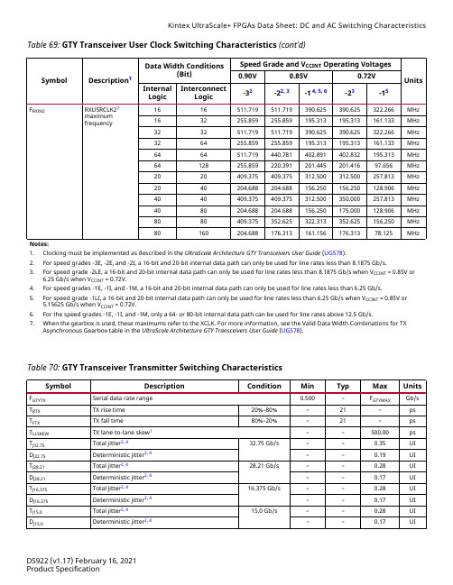
Table 69: GTY Transceiver User Clock Switching Characteristics (cont'd)Symbol Description1Data Width Conditions(Bit)Speed Grade and V CCINT Operating VoltagesUnits0.90V0.85V0.72VInternalLogicInterconnectLogic-32-22, 3-14, 5, 6-23-15F RXIN2RXUSRCLK27maximumfrequency 1616511.719511.719390.625390.625322.266MHz 1632255.859255.859195.313195.313161.133MHz 3232511.719511.719390.625390.625322.266MHz 3264255.859255.859195.313195.313161.133MHz 6464511.719440.781402.891402.832195.313MHz 64128255.859220.391201.445201.41697.656MHz 2020409.375409.375312.500312.500257.813MHz 2040204.688204.688156.250156.250128.906MHz 4040409.375409.375312.500350.000257.813MHz 4080204.688204.688156.250175.000128.906MHz 8080409.375352.625322.313352.625156.250MHz 80160204.688176.313161.156176.31378.125MHzNotes:1.Clocking must be implemented as described in the UltraScale Architecture GTY Transceivers User Guide (UG578).2.For speed grades -3E, -2E, and -2I, a 16-bit and 20-bit internal data path can only be used for line rates less than 8.1875 Gb/s.3.For speed grade -2LE, a 16-bit and 20-bit internal data path can only be used for line rates less than 8.1875 Gb/s when V CCINT = 0.85V or6.25 Gb/s when V CCINT = 0.72V.4.For speed grades -1E, -1I, and -1M, a 16-bit and 20-bit internal data path can only be used for line rates less than 6.25 Gb/s.5.For speed grade -1LI, a 16-bit and 20-bit internal data path can only be used for line rates less than6.25 Gb/s when V CCINT = 0.85V or5.15625 Gb/s when V CCINT = 0.72V.6.For the speed grades -1E, -1I, and -1M, only a 64- or 80-bit internal data path can be used for line rates above 12.5 Gb/s.7.When the gearbox is used, these maximums refer to the XCLK. For more information, see the Valid Data Width Combinations for TXAsynchronous Gearbox table in the UltraScale Architecture GTY Transceivers User Guide (UG578).Table 70: GTY Transceiver Transmitter Switching CharacteristicsSymbol Description Condition Min Typ Max Units F GTYTX Serial data rate range0.500–F GTYMAX Gb/s T RTX TX rise time20%–80%–21–ps T FTX TX fall time80%–20%–21–ps T LLSKEW TX lane-to-lane skew1––500.00ps T J32.75Total jitter2, 432.75 Gb/s––0.35UI D J32.75Deterministic jitter2, 4––0.19UI T J28.21Total jitter2, 428.21 Gb/s––0.28UI D J28.21Deterministic jitter2, 4––0.17UI T J16.375Total jitter2, 416.375 Gb/s––0.28UI D J16.375Deterministic jitter2, 4––0.17UI T J15.0Total jitter2, 415.0 Gb/s––0.28UI D J15.0Deterministic jitter2, 4––0.17UITable : GTY Transceiver User Clock Switching CharacteristicsSymbol Description1Data Width Conditions(Bit)Speed Grade and V CCINT Operating VoltagesUnits0.90V0.85V0.72VInternalLogicInterconnectLogic-32-22, 3-14, 5, 6-23-15F TXOUTPMA TXOUTCLK maximum frequency sourced fromOUTCLKPMA511.719511.719402.891402.832322.266MHzF RXOUTPMA RXOUTCLK maximum frequency sourced fromOUTCLKPMA511.719511.719402.891402.832322.266MHzF TXOUTPROGDIV TXOUTCLK maximum frequency sourced fromTXPROGDIVCLK511.719511.719511.719511.719511.719MHzF RXOUTPROGDIV RXOUTCLK maximum frequency sourced fromRXPROGDIVCLK511.719511.719511.719511.719511.719MHzF TXIN TXUSRCLK7maximumfrequency 1616, 32511.719511.719390.625390.625322.266MHz 3232, 64511.719511.719390.625390.625322.266MHz 6464, 128511.719440.781402.891402.832195.313MHz 2020, 40409.375409.375312.500312.500257.813MHz 4040, 80409.375409.375312.500350.000257.813MHz 8080, 160409.375352.625322.313352.625156.250MHzF RXIN RXUSRCLK7maximumfrequency 1616, 32511.719511.719390.625390.625322.266MHz 3232, 64511.719511.719390.625390.625322.266MHz 6464, 128511.719440.781402.891402.832195.313MHz 2020, 40409.375409.375312.500312.500257.813MHz 4040, 80409.375409.375312.500350.000257.813MHz 8080, 160409.375352.625322.313352.625156.250MHzF TXIN2TXUSRCLK27maximumfrequency 1616511.719511.719390.625390.625322.266MHz 1632255.859255.859195.313195.313161.133MHz 3232511.719511.719390.625390.625322.266MHz 3264255.859255.859195.313195.313161.133MHz 6464511.719440.781402.891402.832195.313MHz 64128255.859220.391201.445201.41697.656MHz 2020409.375409.375312.500312.500257.813MHz 2040204.688204.688156.250156.250128.906MHz 4040409.375409.375312.500350.000257.813MHz 4080204.688204.688156.250175.000128.906MHz 8080409.375352.625322.313352.625156.250MHz 80160204.688176.313161.156176.31378.125MHz。
MC9RS08KA4_8中文数据手册
3FFE
3FFF
BC(JMP 机器码)
跳转地址高字节
跳转地址低字节
飞 3.4 激活背景调试模式 背景调试功能是由 RS08 核内的 BDC 管理的。在软件开发过程中,BDC 提供了
H 一种分析 MCU 操作方法。 C 有 4 种激活背景调试的方法:
*在 POR 期间或发出背景调试强制复位命令之后,拉 BKGD/MS 引脚为低
3
北京飞锐泰克科技有限公司 tel:010-59831537 fax:010-59831536
Prosoft MVI56-MCM ControlLogix 平台 Modbus 通讯模块 说明书

2.9.2.1 功能 5.................................................................................................... 16 2.9.2.2 功能 6 和 16.......................................................................................... 16 2.9.2.3 功能 15.................................................................................................. 17 MVI56-MCM模块和ControlLogix处理器之间的数据流.......................................... 18 2.9.3 从站驱动................................................................................................... 18 2.9.4 主站驱动模式........................................................................................... 20 2.9.4.1 主站命令列表....................................................................................... 21 3 修改模块设置........................................................................................................... 23 3.1 上电................................................................................................................... 23 3.2 运行中更改参数............................................................................................... 23 3.3 装配模块........................................................................................................... 23 3.4 模块数据对象 (MCMModuleDef)................................................................... 29 3.4.1 设置对象................................................................................................... 30 3.4.1.1 数据传输参数 (MCMModule)............................................................. 31
W78E58中文
W78E58B规格书8位微控制器目录:1.概述 (3)2.特性 (3)3.管脚配置 (4)4.管脚描述 (5)5.方块图 (7)6.功能描述 (8)6.1 RAM (8)6.2 定时器0,1,2 (8)6.3 时钟 (9)6.4 晶体振荡器 (9)6.5 外部时钟 (9)6.6 电源管理 (9)6.7 减少EMI辐射 (9)6.8 复位 (9)6.9 I/O口4 (11)6.10 INT2/INT3 (12)6.11 P4口基地址寄存器 (14)6.12 在线编程(ISP)模式 (15)6.13 在线编程控制寄存器(CHPCON) (17)6.14 F04KBOOT 模式(从LDROM启动) (18)7.保密位 (22)7.1 锁止位 (22)禁止 (22)7.2 MOVC7.3 加密 (22)8.电气特性 (23)8.1 绝对最大额定值 (23)8.2 DC特性 (23)出版日期: December 22, 20048.3 AC特性 (25)8.3.1时钟输入波形 (25)8.3.2程序读取周期 (26)8.3.3数据读取周期 (26)8.3.4数据写周期 (27)8.3.5端口访问周期 (27)9.时序波形图 (28)9.1 程序读取周期 (28)9.2 数据读周期 (28)9.3 数据写周期 (29)9.4 端口访问周期 (29)10.典型应用电路 (30)10.1 扩展的外部程序存储器和石英晶体 (30)10.2 扩展的外部程序存储器和振荡器 (31)11.封装尺寸 (32)11.1 DIP40 (32)11.2 44 管脚PLCC (33)11.3 44 管脚PQFP (34)12.应用指南 (35)12.1 ISP 软件编程示例: (35)13.文件版本描述 (42)1. 概述W78E58B是具有带ISP功能的Flash EPROM的低功耗8位微控制器;ISP功能的Flash EPROM可用于固件升级。
A3979中文资料
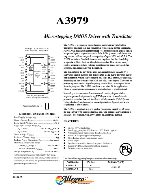
The A3979 is a complete microstepping motor driver with built-inDMOS Microstepping Driver with Translator Functional Block DiagramDMOS Microstepping Driver with TranslatorELECTRICAL CHARACTERISTICS at T A= 25°C, V BB = 35 V, V DD = 3.0 to 5.5 V (unless otherwise noted)Characteristics Symbol Test Conditions Min.Typ.1Max.Units Output DriversLoad Supply Voltage Range V BB Operating8–35V During Sleep mode0–35VOutput Leakage Current2I DSS V OUT = V BB–<1.020μA V OUT = 0 V–<1.0–20μAOutput On Resistance R DS(On)Source driver, I OUT = –2.5 A–0.280.335ΩSource driver, I OUT = 2.5 A–0.220.265ΩBody Diode Forward Voltage V F Source diode, I F = –2.5 A–– 1.4V Sink diode, I F = 2.5 A–– 1.4VMotor Supply Current I BB f PWM < 50 kHz ––8.0mA Operating, outputs disabled–– 6.0mA Sleep mode––20μAControl LogicLogic Supply Voltage Range V DD Operating 3.0 5.0 5.5VLogic Supply Current I DD f PWM < 50 kHz ––12mA Outputs off––10mA Sleep mode––20μALogic Input Voltage V IN(1)0.7×V DD––V V IN(0)––0.3 ×V DD VLogic Input Current2I IN(1)V IN = 0.7 × V DD–20<1.020μA I IN(0)V IN = 0.3 × V DD–20<1.020μAReference Input Voltage Range V REF Operating0–V DD V Reference Input Current I REF–0±3μAHOME Output Voltage V HOME(1)I HOME(1) = –200 μA0.7×V DD––V V HOME(0)I HOME(0) = 200 μA––0.3×V DD VMixed Decay Mode Trip Point V PFDH–0.6 ×V DD–V V PFDL–0.21×V DD–VGain (G m) Error3E G V REF = 2 V, Phase Current = 38.27%––±10% V REF = 2 V, Phase Current = 70.71%––±5.0% V REF = 2 V, Phase Current = 100.00%––±5.0%STEP Pulse Width t W1––μs Blank Time t BLANK R T = 56 kΩ, C T = 680 pF7009501200ns Fixed Off-Time tOFFR T = 56 kΩ, C T = 680 pF303846μs Crossover Dead Time t DT Synchronous rectification enabled100475800ns Continued on the next page...DMOS Microstepping Driver with TranslatorELECTRICAL CHARACTERISTICS, continued at T A= 25°C, V BB = 35 V, V DD = 3.0 to 5.5 V (unless otherwise noted) Characteristics Symbol Test Conditions Min.Typ.1Max.UnitsThermal Shutdown Temperature T JSD–165–°C Thermal Shutdown Hysteresis T JSDHYS–15–°C UVLO Enable Threshold V UVLO Increasing V DD 2.45 2.7 2.95V UVLO Hysteresis V UVLOHYS0.050.10–V1Typical data are for initial design estimations only, and assume optimum manufacturing and application conditions. Performance may vary for individual units, within the specified maximum and minimum limits.2Negative current is defined as coming out of (sourcing from) the specified device pin.3E G = ( [ V REF / 8]– V SENSE ) / ( V REF / 8 ).DMOS Microstepping Driver with TranslatorCharacteristicSymbolTest Conditions*Value Units Package Thermal ResistanceR θJATwo-layer PCB with 3.8 in.2 of copper area on each side connected with thermal vias and to device exposed pad 32ºC/W High-K PCB (multilayer with significant copper areas, based on JEDEC standard)28ºC/W*Additional thermal information available on Allegro Web site.THERMAL CHARACTERISTICS may require derating at maximum conditions, see application informationTemperature (°C)P o w e r D i s s i p a t i o n , P D (W )0.00.52.02.53.03.54.04.55.01.01.520406080100120140160DMOS Microstepping Driver with TranslatorTiming Requirements(T A = +25°C, V DD = 5 V, Logic Levels are V DD and Ground)A.Minimum Command Active TimeBefore Step Pulse (Data Set-Up Time)..... 200 nsB.Minimum Command Active TimeAfter Step Pulse (Data Hold Time)............ 200 nsC.Minimum STEP Pulse Width...................... 1.0 μsD.Minimum STEP Low Time......................... 1.0 μsE.Maximum Wake-Up Time......................... 1.0 msFigure 1. Logic Interface Timing DiagramTable 1. Microstep Resolution Truth TableMS1MS2Microstep Resolution Excitation ModeL L Full Step 2 PhaseH L Half Step1-2 PhaseL H Quarter Step W1-2 PhaseH H Sixteenth Step4W1-2 PhaseDMOS Microstepping Driver with TranslatorDevice Operation. The A3979 is a complete micro-stepping motor driver with a built-in translator for easy operation with minimal control lines. It is designed to operate bipolar stepper motors in full-, half-, quarter-, and sixteenth-step modes. The currents in each of the two output full-bridges (all of the N-channel MOSFETs) are regulated with fixed off-time PMW (pulse width modulated) control circuitry. At each step, the current for each full-bridge is set by the value of its external current-sense resistor (R S1or R S2), a reference voltage (V REF), and the output voltage of its DAC (which in turn is controlled by the output of the translator).At power-on or reset, the translator sets the DACs and the phase current polarity to the initial Home state (shown in figures 2 through 5), and the current regulator to Mixed decay mode for both phases. When a step command signal occurs on the STEP input, the translator automatically sequences the DACs to the next level and current polarity. (See table 2 for the current-level sequence.) The microstep resolution is set by the combined effect of inputs MS1 and MS2, as shown in table 1.While stepping is occurring, if the next output level of the DACs is lower than the immediately preceeding output level, then the decay mode (Fast, Slow, or Mixed) for the active full bridge is set by the PFD input. If the next DAC output level is higher than or equal to the preceeding level, then the decay mode for that full bridge will be Slow decay. This automatic current-decay selection improves microstep-ping performance by reducing the distortion of the current waveform due to back EMF of the motor.RESET Input ( ¯R¯¯E¯¯S¯¯E¯¯T¯ ). The ¯R¯ ¯E¯ ¯S¯ ¯E¯ ¯T¯input (active low) sets the translator to a predefined Home state (shown in figures 2 through 5), and turns off all of the DMOS out-puts. The HOME output goes low and all STEP inputs are ignored until the ¯R¯ ¯E¯ ¯S¯ ¯E¯ ¯T¯input is set to high.Home Output (HOME). The HOME output is a logic output indicator of the initial state of the translator. At power-on, the translator is reset to the Home state (shown in figures 2 through 5).Step Input (STEP). A low-to-high transition on the STEP input sequences the translator and advances the motor one increment. The translator controls the input to the DACs and the direction of current flow in each winding. The size of the increment is determined by the combined state of inputs MS1 and MS2 (see table 1).Microstep Select (MS1 and MS2). The input on terminals MS1 and MS2 selects the microstepping format, as shown in table 1. Any changes made to these inputs do not take effect until the next rising edge of a step command signal on the STEP input.Direction Input (DIR).The state of the DIR input deter-mines the direction of rotation of the motor. Any changes made to this input does not take effect until the next rising edge of a step command signal on the STEP input.Internal PWM Current Control. Each full bridge is controlled by a fixed–off-time PWM current-control circuit that limits the load current to a desired value, I TRIP . Initially, a diagonal pair of source and sink MOS outputs are enabled and current flows through the motor winding and the current sense resistor, R S x. When the voltage across R S x equals the DAC output voltage, the current-sense comparator resets the PWM latch. The latch then turns off either the source MOS-FETs (when in Slow decay mode) or the sink and source MOSFETs (when in Fast or Mixed decay mode).The maximum value of current limiting is set by the selec-tion of R S and the voltage at the V REF input with a transcon-ductance function approximated by:I TRIP max = V REF/8R SThe DAC output reduces the V REF output to the cur-rent-sense comparator in precise steps (see table 2 for% I TRIP max at each step).I TRIP = (% I TRIP max/100) I TRIP maxIt is critical that the maximum rating (0.5 V) on either the SENSE1 and SENSE2 pins is not exceeded. For full step-ping, V REF can be applied up to the maximum rating of V DD because the peak sense value is 0.707 × V REF/ 8. In all other modes, V REF should not exceed 4 V.Functional DescriptionDMOS Microstepping Driver with TranslatorFixed Off-Time. The internal PWM current-control cir-cuitry uses a one-shot timer to control the duration of time that the MOSFETs remain off. The one shot off-time, t OFF, is determined by the selection of external resistors, R T x , and capacitors, C T x, connected from each R C x timing terminal to ground. The off-time, over a range of values of C T = 470 pF to 1500 pF and R T = 12 kΩ to 100 kΩ is approximated by:t OFF = R T C TRC Blanking. In addition to the fixed off-time of the PWM control circuit, the CTx component sets the compara-tor blanking time. This function blanks the output of the current-sense comparators when the outputs are switched by the internal current-control circuitry. The comparator outputs are blanked to prevent false overcurrent detection due to reverse recovery currents of the clamp diodes, or to switching transients related to the capacitance of the load. The blank time t BLANK can be approximated by:t BLANK= 1400C TCharge Pump (CP1 and CP2). The charge pump is used to generate a gate supply greater than that of VBB for driving the source-side DMOS gates. A 0.22 μF ceramic capacitor should be connected between CP1 and CP2 for pumping purposes. In addition, a 0.22 μF ceramic capacitor is required between VCP and VBB, to act as a reservoir for operating the high-side DMOS gates.V REG(VREG). This internally-generated voltage is used to operate the sink-side DMOS outputs. The VREG pin must be decoupled with a 0.22 μF capacitor to ground. V REG is internally monitored, and in the case of a fault condition, the DMOS outputs of the device are disabled.Enable Input (¯E¯¯N¯¯A¯¯B¯¯L¯¯E¯). This active-low input enables all of the DMOS outputs. When set to a logic high, the outputs are disabled. The inputs to the translator (STEP, DIR, MS1, and MS2), all remain active, independent of the ¯E¯¯N¯¯A¯¯B¯ ¯L¯¯E¯ input state.Shutdown. During normal operation, in the event of a fault, such as overtemperature (excess T J) or an undervolt-age on VCP, the outputs of the device are disabled until the fault condition is removed.At power up, and in the event of low V DD, the undervoltage lockout (UVLO) circuit disables the drivers and resets the translator to the Home state.Sleep Mode( ¯S¯¯L¯¯E¯¯E¯¯P¯). This active-low control input is used to minimize power consumption when the motor is not in use. It disables much of the internal circuitry includ-ing the output DMOS FETs, current regulator, and charge pump. Setting this to a logic high allows normal operation, as well as start-up (at which time the A3979 drives the motor to the Home microstep position). When bringing the device out of Sleep mode, in order to allow the charge pump (gate drive) to stabilize, provide a delay of 1 ms before issu-ing a step command signal on the STEP input.Percent Fast Decay Input (PFD). When a STEP input signal commands a lower output current than the previous step, it switches the output current decay to either Slow, Fast, or Mixed decay mode, depending on the voltage level at the PFD input. If the voltage at the PFD input is greater than 0.6 × V DD, then Slow decay mode is selected. If the voltage on the PFD input is less than 0.21 × V DD , then Fast decay mode is selected. Mixed decay mode is selected when V PFD is between these two levels, as described inthe next section. This terminal should be decoupled with a 0.1 μF capacitor.Mixed Decay Operation. If the voltage on the PFD inputis between 0.6 × V DD and 0.21 × V DD, the bridge operates in Mixed decay mode, as determined by the step sequence (shown in figures 2 through 5). As the trip point is reached, the device goes into Fast decay mode until the voltageon the RCx terminal decays to the same level as voltage applied to the PFD terminal. The time that the device oper-ates in fast decay is approximated by:t FD = R T C T ln (0.6V DD/V PFD)After this Fast decay portion, the device switches to Slow decay mode for the remainder of the fixed off-time period.DMOS Microstepping Driver with TranslatorSynchronous Rectification. When a PWM off-cycle is triggered by an internal fixed–off-time cycle, load current recirculates according to the decay mode selected by the control logic. The A3979 synchronous rectification feature turns on the appropriate MOSFETs during the decay of the current, and effectively shorts out the body diodes with the low R DS(On) driver. This reduces power dissipation significantly and eliminates the need for external Schottky diodes for most applications. The synchronous rectification can be set to either Active mode or Disabled mode:• Active Mode. When the SR input is logic low, Active mode is enabled and synchronous rectification can occur. This mode prevents reversal of the load current by turning off synchronous rectification when a zero current level is detected. This prevents the motor winding from conduct-ing in the reverse direction.• Disabled Mode. When the SR input is logic high, syn-chronous rectification is disabled. This mode is typi-cally used when external diodes are required to transfer power dissipation from the A3979 package to the external diodes.Layout. The printed circuit board on which the device is mounted should have a heavy ground plane. For optimum electrical and thermal performance, the A3979 should be soldered directly onto the board.The load supply terminals, VBB x, should be decoupled with an electrolytic capacitor (>47 μF is recommended), placed as close to the device as possible.To avoid problems due to capacitive coupling of the high dv / dt switching transients, route the bridge-output traces away from the sensitive logic-input traces.Always drive the logic inputs with a low source impedance to increase noise immunity.Grounding. The AGND (analog ground) terminal and the PGND (power ground) terminal must be connected together externally.All ground lines should be connected together and be as short as possible. A star ground system, centered under the device, is an optimum design.The copper ground plane located under the exposed thermal pad is typically used as the star ground.Current Sensing. To minimize inaccuracies caused by ground-trace IR drops in sensing the output current level, the current-sense resistors, R S x, should have an independent ground return to the star ground of the device. This path should be as short as possible.For low-value sense resistors, the IR drops in the printed cir-cuit board sense resistor traces can be significant and should be taken into account.The use of sockets should be avoided as they can introduce variation in R S x due to their contact resistance.Allegro MicroSystems recommends a value of R S given byR S = 0.5/I TRIP maxThermal Protection. This internal circuitry turns offall drivers when the junction temperature reaches 165°C, typical. It is intended only to protect the device from failures due to excessive junction temperatures and should not imply that output short circuits are permitted. Thermal shutdown has a hysteresis of approximately 15°C.Applications InformationDMOS Microstepping Driver with TranslatorPhase 2I OUT2BDirection =H(%)Phase 1I OUT1ADirection =H(%)STEP Input HOME OutputPhase 2I OUT2BDirection =H(%)Phase 1I OUT1ADirection =H(%)STEP Input HOME OutputPhase 2I OUT2ADirection =H(%)Phase 1I OUT1ADirection =H(%)STEP Input HOME OutputFigure 4. Decay Modes for Quarter-Step IncrementsFigure 3. Decay Modes for Half-Step IncrementsFigure 2. Decay Mode for Full-Step IncrementsDMOS Microstepping Driver with TranslatorFigure 5. Decay Modes for Sixteenth-Step IncrementsPhase 2I OUT2BDirection =H(%)Phase 1I OUT1ADirection =H(%)STEP Input HOME OutputDMOS Microstepping Driver with TranslatorTable 2. Step Sequencing SettingsHome microstep position at Step Angle 45º; DIR = H; 360° = 4 full stepsDMOS Microstepping Driver with TranslatorTerminal List TableNumber Name Description1SENSE1Sense resistor for Bridge 12HOME Logic Output3DIR Logic input4OUT1A Output A for Bridge 15PFD Mixed decay setting6RC1Analog input for fixed off-time for Bridge 17AGND Analog Ground8REF Current trip reference voltage input9RC2Analog input for fixed off-time for Bridge 210VDD Logic supply11OUT2A Output A for Bridge 212MS2Logic input13MS1Logic input14SENSE2Sense resistor for Bridge 215VBB2Load supply for Bridge 216SR Logic input17¯R¯¯E¯¯S¯¯E¯¯T¯Logic input18OUT2B Output B for Bridge 219STEP Logic input20VREG Regulator decoupling21PGND Power Ground22VCP Reservoir capacitor23CP1Charge pump capacitor 124CP2Charge pump capacitor 2251OUT1B Output B for Bridge 126¯E¯¯N¯¯A¯¯B¯¯L¯¯E¯Logic input27¯S¯¯L¯¯E¯¯E¯¯P¯Logic input28VBB1Load supply for Bridge 1LP Package, 28-Pin TSSOP with Exposed Thermal PadThe products described here are manufactured under one or more U.S. patents or U.S. patents pending.Allegro MicroSystems, Inc. reserves the right to make, from time to time, such de p ar t ures from the detail spec i f i c a t ions as may berequired to permit improvements in the per f or m ance, reliability, or manufacturability of its products. Before placing an order, the user is cautioned to verify that the information being relied upon is current.Allegro ® products are not authorized for use as critical components in life-support devices or syst ems without express written approval. The in f or m a t ion in c lud e d herein is believed to be ac c u r ate and reliable. How e v e r, Allegro MicroSystems, Inc. assumes no re s pon s i b il i t yfor its use; nor for any in f ringe m ent of patents or other rights of third parties which may result from its use.Copyright©2005 AllegroMicrosystems, Inc.A B Terminal #1 mark area。
Honeywell MICRO SWITCH V7系列高级微型基本开关数据手册说明书

V7-1A17D8-048V7-1C17D8-207V7-1C17E9V7-1C27E9V7-1S17D8 V7-2B17D8-201V7-5F17D8V7-6B19D8-057V7-1A17D8-057V7-7B19E9MICRO SWITCH™Premium Miniature Basic Switches Datasheet2What makes our switches better?Certified with CSA, ENEC, and UL for global acceptability Reliable snap-spring mechanism with more than 60 years ofproven service Available with pin plungers, integral levers (fitted two posi-tions), or auxiliary levers to meet equipment requirements Electrical ratings from 0.1 A up to 25 A fordesign flexibility in one package sizeMICRO SWITCH™ V7 SeriesPremium Miniature Basic SwitchesHoneywell’s MICRO SWITCH™ V7 miniature switches are designed for long term-reliability in a rugged switchpackaged with a thermoplastic housing. These switches may be installed in a wide range of applications from simple or precision on/off limits, presence/absence sensing, or embedded in pressure or temperature assemblies.The V7 switch is available as a pin plunger style or with optional integral or auxiliary levers to actuate the switch and offer versatility in the application. The switch requires as little as 0,15 Newtons [approximately ½ ounce] to operate for extremely sensitive applications or an operating force of almost 4 Newtons [14 ounces] where higher forces are required. The V7 switch can reliably control logic level electrical loads from less than 0.1 A to power duty switching up to 25 A. Agency certifications for the MICRO SWITCH™ V7 switches are provided through CSA, ENEC, and UL for global use around the world.COST OPTIMIZATION • RELIABILITYPERFORMANCE • GLOBAL ACCEPTANCEBig performance in a small package.3Features and BenefitsACTUATION ON TIMEMICRO SWITCH™ V7 Series basic switches operate with forces as low as 15 g and carry options to increase to 397 g, and can thereby easily accommodate different actuator mechanisms.RELIABLE PERFORMANCE IN HARSH CONDITIONSSwitches feature industry-leading temperature ranges of -40 °C to 175 °C [-40 °F to 347 °F] to allow for years of reliable performance in harsh conditions.LONG LIFE CYCLE RATINGThe long life cycle rating (up to 10,000,000 cycles ) reduces the need to replace switches over the life of OEM platform applications, therefore reducing total system cost.DESIGN FLEXIBILITYAvailable with pin plungers, integral levers (fitted 2 positions), and auxiliary levers to meet a variety of equipment requirements, MICRO SWITCH™ V7 Series switches also boast electrical ratings from 0.1 A up to 25 A for design flexibility in one package size.Global acceptance: UL, CSA, ENECVENDING MACHINE MOTORSSwitch controls motors or solenoids in vending machines for dispensing of product.MICROWAVE DOOR INTERLOCKSwitch in door interlock of microwave that disconnects power if door opened.OVEN CLEANING LATCHSwitch in door latch for oven clean operation.PRESSURE SWITCH ASSEMBLYPressure switch senses incoming water pressure for power washer.Potential Applications4V7 SeriesPRODUCT NOMENCLATUREV7Switch Type 1Operating Force1Termination Style(Inches)5Electric ratings “W” x “X” only used with “A” Mounting Construction and vice versa 6European ENEC rating requires Mounting Construction code “9” or “0”Electrical Rating 3,6CV7 Series Miniature Circuitry CodeMounting/Construction 4,61Use only if this switch has a special feature.Could be any number.Special Designator7D8Lever Style 2North Europe ——MICRO SWITCH™ Premium Miniature Basic Switches1 Incandescent lamp rating2 XX(Y) - XX = max. rated resistive value in amps, and (Y) = max. rated inductive value in amps3 European ENEC rating requires Mounting Construction code “9” or “0”. See page four, Mounting Construction column5BZ/BA Type[0.87 in]*3,1 mm mtg holes[0.81 in]** 177 °C [350 °F]78V7 SeriesAVAILABLE TERMINALS Quick Connect (QC)D8 Terminals: 0.187 in wide x 0.020 in thick.E8 Terminals: 0.187 in wide x 0.020 in thick.E9 Terminals: 0.250 in wide x 0.032 in thick.Printed Circuit Board (PO2)These terminals interface with snap-on receptacles and other components from AMPMODU interconnection system.MICRO SWITCH™ Premium Miniature Basic SwitchesThis Honeywell datasheet supports the following MICRO SWITCH™ V7 Series Basic Switch ListingsV7-1C17D8-002 V7-1C37D855-002 V7-6C18D8-002 V7-1C27D855-002 V7-1C33D855-002 V7-1C39D8-002 V7-1C17E9-002V7-6C28E9-002V7-1B17D8-022 V7-1B19D8-022 V7-1C17D8-022 V7-3S17E9-022V7-6B19E9-022V7-1S17D8-022V7-2B17D8-022 V7-3S17D8-022V7-1B29P07-022 V7-1C18E9-022V7-3E17E9-022V7-2B27D8-022 V7-2S17D8-022V7-9W1AE9-022 V7-1Z19E9-022V7-2B17D8-048 V7-1V19E9-048V7-1C17D8-048 V7-1X2AD8-048 V7-9W1AE9-048 V7-1B17D8-048 V7-3S17D8-048V7-9W2AE9-048 V7-7B17D8-048 V7-1A17D8-048V7-2B29E9-048V7-2B19E9-048V7-6C18D8-048 V7-1B27D8-048 V71A17D8048V7-1C17D8-201 V7-7B17D8-201 V7-1C13D8-201 V7-2B17D8-201 V7-1C17E9-201V7-2S17D8-201V7-6B19E9-201V7-1S17D8-201V7-7B17D862-201 V7-1D19D8-201 V7-3A17D8-201V7-1D10E9-201V7-1V17D8-201V7-1C17D8-207V7-1B17D8-207V7-2B17D8-207V7-1C17E9-207V7-2A17D8-207V7-1V19E9-207V7-1B10E9-207V7-1A27D8-207V7-7D17D8-207V7-2S17D8-207V7-1S17D8-207V7-1C17D8-263V7-1B17D8-263V7-6C17D8-263V7-1Z10E9-263V7-1S17D8-263V7-1C27E9-263V7-1V29E9-263V7-3E19E9-263V71Z10E9-263V7-7B19D8-263V7-1S18D8-263V7-1B37D8-263V7-3A17D8-263V7-1B178-263V7-1A27D8-636V7-1C17D8V7-2B17D8V7-1V39E9V7-1Z19E9V7-1B37D8V7-2S17D8V7-1C17E9V7-1C37D8V7-1Z29E9V7-3E17D8V7-5F17D8V7-7B17D8V7-1S17D8V7-1V19E9V7-3E17E9V7-1Z20E9V7-4A17D8V7-5F27E9V7-1Y39E9V7-1V29E9V7-1D10D8V7-2B17E9V7-6C17D8V7-4S17D8V7-1Y19E9V7-1C27E9V71Z10E9V7-1B17D8V7-6B19D8V7-1C18D8V7-1A17D8V7-2B29D8V7-5D17E9V7-3A17D8V7-4S37D8V7-7B19E9V7-1Z10E9V7-2A17E9V7-5F27D8V7-3S17E9V7-1S10D8V7-1Z39E9V7-2B27E9V7-3E19E9V7-1A17P02V7-4S27D8V7-7B27D8V7-1Z13E9V7-1Z30E9V7-2A27D8V7-7A19D8V7-2B37E9V7-1C29D8V7-1C13E9V7-3A18D8V7-9W2AE9V7-4A18E9V7-9W1AE9V7-1A28D8V7-1B19E9V7-1K29E9V7-2B17-D8V7-3E10E8V7-6C37E9-036V7-1C27D94V7-1C17D8-295V7-1C29D7V7-1Z13E993V7-1V19E9-269V7-6C13D8-132V7-6B19D8-057V7-2B17D8-162V7-4A29E8-424V7-1C17D844V7-1B17D8-122V7-1C17D844-429V7-7A19D8-374V7-4A17D8-407V7-5F17D8-289V7-6C17D8-057V7-2B29D8-384V7-1X1AD8-304V7-6C17D8-162V7-1A23E9-172V7-1X2AD9C2V7-1C27E9-292V7-2S17E9-420V7-1C17D8-294V7-7B17D8-073V7-3S17D8-148V7-7C19D8-640V7-1V19E994-403V7-1A17D8-057V7-1E17D8-366V7-5F17D8-336V7-1C17E9-292V7-6A17D8-057V7-2E17E9-420V7-6C17D8-439V7-1X1AD9C1V7-7B10D8-274V7-7B19D8-426V7-3E17D8-148V7-1A28D882V7-7B29D883V7-7B17D8-481V7-2E17E9-366V7-1C29E7V7-1S19D8-369V7-7B19D8-640V7-7B17D8-140V7-1X2AE9-292V7-1Z13E987V7-1X2AD8-294V7-6B19D8-672V7-7B29E9-053V7-1V20E94V7-1B19D8-36915PA177-V715PA2609V7 SeriesADDITIONAL INFORMATIONThe following associated literature is available on the Honeywell web site at :• Product installation instructions• Product range guide• Product nomenclature tree• Product application-specific information– Application note: Electronic sensors and electromechanicalswitches in valves and flow meters– Application note: Electronic sensors and MICRO SWITCH ™switches in industrial air compressors– Application note: Sensors and switches for HVAC/Rapplications– Application note: Sensors and switches in oil rig applications– Application note: Sensors and switches in sanitary valves– Application note: Sensors and switches for valve monitors and valve indicators– Application note: Treadmill equipment– Application note: V7 available terminals– Technical bulletin: Applying precision switches– Technical bulletin: Low energy switch guideWARRANTY/REMEDYHoneywell warrants goods of its manufacture as being free of defective materials and faulty workmanship. Honeywell’s standard product warranty applies unless agreed to otherwise by Honeywell in writing; please refer to your order acknowledgement or consult your local sales office for specific warranty details. If warranted goods are returned to Honeywell during the period of coverage, Honeywell will repair or replace, at its option, without charge those items it finds defective. The foregoing is buyer’s sole remedy and is in lieu of all other warranties, expressed or implied, including those of merchantability and fitness for a particu-lar purpose. In no event shall Honeywell be liable for conse-quential, special, or indirect damages.While we provide application assistance personally, through our literature and the Honeywell website, it is up to the customer to determine the suitability of the product in the application. Specifications may change without notice. The information we supply is believed to be accurate and reliable as of this printing. However, we assume no responsibility for its use.004987-2-EN IL50 GLO January 2015Copyright © 2015 Honeywell International Inc. All rights reserved.Sensing and Control Honeywell1985 Douglas Drive North Golden Valley, MN 55422 Find out moreHoneywell serves its customers through a worldwide network of sales offices, representatives and distributors. For application assistance, current specifications, pricing or name of the nearest Authorized Distributor, contact your local sales office.To learn more about Honeywell’s sensing and control products, call +1-815-235-6847 or 1-800-537-6945,visit , or e-mail inquiries to *********************V7-1B17D8-048-S V7-7D17D8-207V7-1A17D8-057V7-1A17D8-048V7-1C17D8-207V7-1C17E9V7-1C27E9V7-1S17D8 V7-2B17D8-201V7-5F17D8V7-6B19D8-057V7-1A17D8-057V7-7B19E9。
A4989SLDTR-T;中文规格书,Datasheet资料
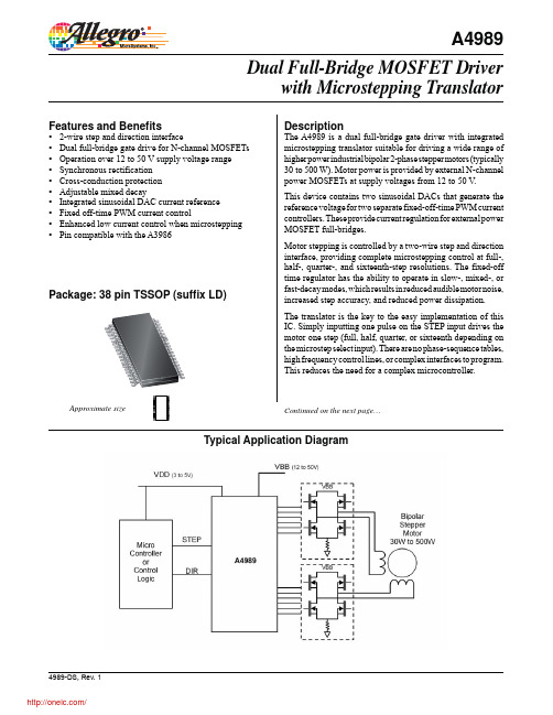
Selection Guide
Part Number A4989SLDTR-T Packing Tape and reel, 4000 pieces per reel
Absolute Maximum Ratings
Characteristic Supply Voltage Logic Supply Voltage Logic Inputs and Outputs SENSEx pins Sxx pins LSSx pins GHxx pins GLxx pins Cxx pins Operating Ambient Temperature Junction Temperature Storage Temperature TA TJ(max) Tstg Range S Symbol VBB VDD Notes Rating –0.3 to 50 –0.3 to 7 –0.3 to 7 –1 to 1 –2 to 55 –2 to 5 Sxx to Sxx+15 –2 to 16 –0.3 to Sxx+15 –20 to 85 150 –55 to 150 Units V V V V V V V V V ºC ºC ºC
The above-supply voltage required for the high-side N-channel MOSFETs is provided by a bootstrap capacitor. Efficiency is enhanced by using synchronous rectification and the power FETs are protected from shoot-through by integrated crossover control and programmable dead time.
autonics旋转编码器中文选型手册及说明书
>4@PUT B ?4@PUT B N4@PUT C D4@PUT C c4@PUT Z C4@PUT Z F4@1V.;VED O;,/ c4@HOE.6V/ yQ@GM H
Nb@f OQO JuI\m@f ul@f
\g.w@f
/; @f m4 /;
Q
PUT B >4 Q
B
PUT C N4 B
C PUT Z c4 C
B2 C2 Z ]J\g.w B2 B2 C2 C2 Z2 Z ]K
.Ogk^8/
Mgn Ib`a
B]<C]4O@fq]S`L
T :
OT >
JTAB]qp1<{K
,*ul @ N[o4 96eB2 [kul @ N[o4 64:VED
,*ul @ N[o4 76eB2 @ful.uzul ;VED/@Nbf4 .uzul3846/VED2 @ful.uzul 7838:VED/@Nbf4 .uzul3946/VED
376 q =6?.RSVBG/2 Pi@38; q >;? 9;q>;,RI2 Pi@ 9;q?6,RI
JQ;6.JFD TC/
@;ee2 ;Q2 by@8e2 yQud.\g.w@@;ee2 >Q/
@<ee TChRK=~
@>ee K=~Jk,K6T>uw=e7
k|4 786`
.\g.w@fgO/
=;6VBD ;65<6Ip 7 *9.EvzE<O^4O/ udhR}:2 l866eeudqhR~hRe
=eLN[o4 :6`_ \e.6466:O e/ 8_eLN[o4 :6`_ \e.6466:O e/ N[o4 :6` \e8 .: =763< c` e8/ X` @ N[o4 8c`_2 =` @ N[o4 7c`_ ;666ihe 76 q ;;Ip1+74;ee X2 Y2 Z2}`|b8 N[o4 ;6H
v7四轴点胶机控制器-手持版说明书V7
双Y智能点胶机控制系统(手持版)说明书目录1.产品介绍 (3)1.1产品概述 (3)1.2功能简介 (3)1.3功能特性 (3)1.4产品列表 (4)2.接线说明图 (5)2.1 控制器接线引脚定义 (5)2.2 控制器接线说明....... . (6)2.3 系统连接示意图 (7)2.4 转接板接线说明 (8)2.5 转接板接线示意图............................................................................................ . (9)2.6 安装尺寸.......................................................................................................... (10)3.按键说明 (11)3.1手持盒按键图 (11)3.2手持盒按键说明 (11)4.手持盒操作说明 (13)4.1开机画面介绍 (13)4.2主菜单功能介绍 (15)4.3新增功能操作 (19)4.4插入指令操作 (28)4.5删除指令操作 (28)4.6复制指令操作 (28)4.7 Y1复制到Y2操作 (28)4.8阵列复制操作 (29)4.9偏移操作 (29)4.10批量修改 (30)4.11自动圆角 (30)4.12类型批量修改 (30)4.13系统 (31)4.14执行方式操作 (33)4.15复位方式操作 (33)4.16产量设定 (34)4.17默认参数 (34)4.18拉丝工艺 (35)4.19停机位置 (35)4.20空移速度 (36)4.21定滴功能 (36)4.22对针操作 (37)4.23 MARK点对针操作 (37)5.注意事项 (38)5.1装机事项 (38)1.产品介绍1.1产品概述本系统是由本公司专业数控团队为点胶机行业量身定做的低成本、高浓缩、高集成度的智能点胶机控制系统。
