EEEFK1A330R中文资料
RCWE0603R330FKEA;RCWE1210R240FKEA;RCWE0603R200FKEA;RCWE0603R240FKEA;中文规格书,Datasheet资料

GLOBAL PART NUMBER INFORMATION
Part Number: RCWE060351L0FNEA
R
C
W
E
0
6
0
3
5
1
L
0
F
N
E
A
GLOBAL MODEL RCWE0402 RCWE0603 RCWE0805 RCWE1206 RCWE1210 RCWE2010 RCWE2512 Revision: 12-Dec-11
PERFORMANCE
TEST Thermal shock Short time overload High temperature exposure Temperature cycling Biased humidity Mechanical shock Vibration Operational life Resistance to solder heat Moisture resistance MIL-STD-202, method 107, - 55 °C to + 125 °C, 300 cycles at each extreme 2 x rated power; duration according the model MIL-STD-202, method 108, 1000 h at T = 125 °C, 0 % power JESD 22, method JA-104, 1000 cycles (- 55 °C to + 125 °C) MIL-STD-202, method 103, 1000 h 85 °C/85 % RH, 10 % x (P x R)1/2 MIL-STD-202, method 213, condition C, 10 g’s, 6 ms (half sine), 3 directions MIL-STD-202, method 108, 1000 h at T = 125 °C at rated power MIL-STD-202, method 106, 0 % power, 7a and 7b not required
艾森 Moeller 系列 PKZM0 电机保护开关说明书

Eaton 199193Eaton Moeller® series PKZM0 Motorschutzschalter, 0,25 kW, 0,63 - 1 A, Einspeiseseitig Schraubklemmen/Abgangsseitig Push-in-Klemmen, MSCAllgemeine spezifikationEaton Moeller® series PKZM0 Motor-protective circuit-breaker19919375 mm102 mm 45 mm 0.274 kgVDE 0660 IEC/EN 60947 UL File No.: E36332 IEC/EN 60947-4-1 CSA File No.: 165628UL Category Control No.: NLRV ULCSA-C22.2 No. 60947-4-1-14 CSA Class No.: 3211-05 CSAUL 60947-4-1 CE UL CSA4015081972777PKZM0-1-SPI32ProduktnameKatalognummer Produkt Länge/Tiefe Produkthöhe Produktbreite Produktgewicht Zertifikat(e)EANModellcodeDrehknopfPhasenausfallempfindlichkeit (gemäß IEC/EN 60947-4-1, VDE 0660 Teil 102)MotorschutzPhasenausfallempfindlich3-polig 100.000 Schaltvorgänge100.000 SchaltvorgängeHutschienenmontage optionalAufschnappbar auf Hutschiene IEC/EN 60715 mit 7,5 oder 15 mm Höhe.40 Schaltspiele/hIII3MotorschutzschalterFinger- und handrückensicher, Berührungsschutz bei senkrechter Betätigung von vorne (EN 50274)6000 V AC25 g, Mechanisch, entsprechend IEC/EN 60068-2-27, Halbsinusstoß 10 msAuch Motoren mit Effizienzklasse IE3Nebenstromkreis: Manueller Typ E bei Einsatz mit Klemme, oder geeignet für Gruppeninstallationen, (UL/CSA)≤ 0,25 %/K, Restfehler für T > 40°-25 - 55 °C, Arbeitsbereich-5 - 40 °C gemäß IEC/EN 60947, VDE 0660Motorstarterkombinationen Typ MSC…Stellgliedtyp Merkmale Funktionen Polzahl Lebensdauer, elektrischLebensdauer, mechanisch MontagemethodeEinbaulageBetriebsfrequenzÜberspannungskategorie VerschmutzungsgradProduktkategorieSchutzBemessungsstoßspannungsfestigkeit (Uimp) SchockfestigkeitGeeignet fürTemperaturkompensationVerwendet mitMax. 2000 m-25 °C55 °C-25 °C40 °C-40 °C80 °CFeuchte Wärme, konstant, nach IEC 60068-2-78 Feuchte Wärme, zyklisch, nach IEC 60068-2-301 x (1 - 6) mm²12 mm1,7 Nm, Schraubklemmen, Hauptleiter50 Hz60 Hz1 A0.12 kW0.25 kW690 V690 V1 A50 kA, 600 Y/347 V, SCCR (UL/CSA)65 kA, 240 V, SCCR (UL/CSA)65 kA, 480 Y/277 V, SCCR (UL/CSA)± 20% Toleranz, Auslöserblöcke15,5 A, Irm, Einstellbereich max.Grundgerät befestigt 15,5 x lu, Auslöserblöcke Einspeiseseitige Schraubklemmen Abgangsseitige Push-In-KlemmenHöheUmgebungsbetriebstemperatur – min Umgebungsbetriebstemperatur – max Umgebungsbetriebstemperatur (gekapselt) – min Umgebungsbetriebstemperatur (gekapselt) – max Umgebungstemperatur Lagerung - min Umgebungstemperatur Lagerung - max Klimafestigkeit Anschlusskapazität (feindrähtig)Abisolierlänge (Hauptleiter)AnzugsdrehmomentBemessungsfrequenz - minBemessungsfrequenz - max Bemessungsbetriebsstrom (Ie) Bemessungsbetriebsleistung bei AC-3, 220/230 V, 50 Hz Bemessungsbetriebsleistung bei AC-3, 380/400 V, 50 Hz Bemessungsbetriebsspannung (Ue) - min Bemessungsbetriebsspannung (Ue) - max Bemessungsdauerstrom (Iu)Bemessungskurzschlussstrom (Typ E)KurzschlussauslöserVerbindungAnzahl der Hilfskontakte (Wechsler)0 1 A1 AÜberlastauslöser: Auslöseklasse 10 A5.33 W0 W0 W0 WAnforderungen der Produktnorm sind erfüllt.Anforderungen der Produktnorm sind erfüllt.Anforderungen der Produktnorm sind erfüllt.Anforderungen der Produktnorm sind erfüllt.Anforderungen der Produktnorm sind erfüllt.Unzutreffend, da die gesamten Schaltgeräte überprüft werden müssen.Unzutreffend, da die gesamten Schaltgeräte überprüft werden müssen.Anforderungen der Produktnorm sind erfüllt.DA-DC-00004917.pdfDA-DC-00004887.pdfETN.PKZM0-1-SPI32.edzIL122024ZUWIN-WIN mit Push-in-TechnikProduktübersicht für den Maschinenbau Sortimentskatalog Motoren schalten und schützenpkzm0_s32_pi.stppkzm0_s32_pi.dwgeaton-manual-motor-starters-pkz-dimensions-002.eps121X002121X042eaton-manual-motor-starters-pkzm-pkzm0-dimensions-003.eps eaton-manual-motor-starters-pkz-dimensions.epsAnzahl der Hilfskontakte (Öffner)Anzahl Hilfskontakte (Schließer)Überlastauslösestromeinstellung - minÜberlastauslösestromeinstellung - maxAuslösecharakteristikGeräteverlustleistung, stromabhängig pvid Verlustleistungskapazität PdissVerlustleistung pro Pol, stromabhängig, PvidStatische Verlustleistung, stromunabhängig PVS10.2.2 Korrosionsbeständigkeit10.2.3.1 Wärmebeständigkeit von Umhüllung10.2.3.2 Widerstandsfähigkeit Isolierstoffe gewöhnliche Wärme 10.2.3.3 Widerst. Isolierstoffe abnorm. Wärme/Feuer durch int. elektr. Auswirk.10.2.4 Beständigkeit gegen UV-Strahlung10.2.5 Heben10.2.6 Schlagprüfung10.2.7 Beschriftungen Declarations of conformity eCAD model Installationsanleitung Installationsvideos KatalogemCAD model Zeichnungen10.3 Schutzart von BaugruppenUnzutreffend, da die gesamten Schaltgeräte überprüft werden müssen.10.4 Luft- und KriechstreckenAnforderungen der Produktnorm sind erfüllt.10.5 Schutz gegen elektrischen SchlagUnzutreffend, da die gesamten Schaltgeräte überprüft werden müssen.10.6 Einbau von BetriebsmittelnUnzutreffend, da die gesamten Schaltgeräte überprüft werden müssen.10.7 Innere Stromkreise und VerbindungenLiegt in der Verantwortung des Schaltanlagenbauers.10.8 Anschlüsse für von außen eingeführte LeiterLiegt in der Verantwortung des Schaltanlagenbauers.10.9.2 Betriebsfrequente SpannungsfestigkeitLiegt in der Verantwortung des Schaltanlagenbauers.10.9.3 StoßspannungsfestigkeitLiegt in der Verantwortung des Schaltanlagenbauers.10.9.4 Prüfung von Umhüllungen aus IsolierstoffLiegt in der Verantwortung des Schaltanlagenbauers.10.10 ErwärmungDie Erwärmungsberechnung liegt in der Verantwortung des Schaltanlagenbauers. Eaton stellt Verlustleistungsdaten der Geräte bereit.10.11 KurzschlussfestigkeitLiegt in der Verantwortung des Schaltanlagenbauers. Die Spezifikationen für die Schaltgeräte müssen beachtet werden.10.12 Elektromagnetische VerträglichkeitLiegt in der Verantwortung des Schaltanlagenbauers. Die Spezifikationen für die Schaltgeräte müssen beachtet werden.10.13 Mechanische FunktionDas Gerät erfüllt die Anforderungen, wenn die Informationen in der Montageanweisung (IL) beachtet werden.Eaton Konzern plc Eaton-Haus30 Pembroke-Straße Dublin 4, Irland © 2023 Eaton. Alle Rechte vorbehalten. Eaton ist eine eingetrageneMarke.Alle anderen Warenzeichen sindEigentum ihrer jeweiligenBesitzer./socialmedia。
卓顶精文最新欧科变频器说明书文档.doc
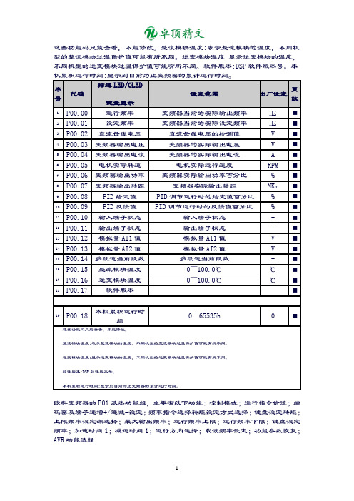
这些功能码只能查看,不能修改。
整流模块温度:表示整流模块的温度,不同机型的整流模块过温保护值可能有所不同。
逆变模块温度:显示逆变模块的温度,不同机型的逆变模块过温保护值可能有所不同。
软件版本:DSP软件版本号。
本机累积运行时间:显示到目前为止变频器的累计运行时间。
序号代码描述LED/OLED键盘显示设定范围出厂设定更改1P00.00 运行频率变频器当前的实际输出频率HZ ■2P00.01 设定频率变频器当前的实际设定频率HZ ■3P00.02 直流母线电压直流母线电压的检测值V ■4P00.03 变频器输出电压变频器的实际输出电压V ■5P00.04 变频器输出电流变频器的实际输出电流 A ■6P00.05 电机实际转速电机实际运行速度RPM ■7P00.06 变频器输出功率变频器实际输出功率百分比% ■8P00.07 变频器输出转距变频器实际输出转距NKm ■9P00.08 PID给定值PID调节运行时的给定值百分比% ■10P00.09 PID反馈值PID调节运行时的反馈值百分比% ■11P00.10 输入端子状态输入端子状态- ■12P00.11 输出端子状态输出端子状态- ■13P00.12 模拟量AI1值模拟量AI1值V ■14P00.13 模拟量AI2值模拟量AI2值V ■15P00.14 多段速当前段数多段速当前段数- ■16P00.15 整流模块温度0~100.0℃℃■17P00.16 逆变模块温度0~100.0℃℃■18P00.17 软件版本■19P00.18 本机累积运行时间0~65535h 0 ■这些功能码只能查看,不能修改。
整流模块温度:表示整流模块的温度,不同机型的整流模块过温保护值可能有所不同。
逆变模块温度:显示逆变模块的温度,不同机型的逆变模块过温保护值可能有所不同。
软件版本:DSP软件版本号。
本机累积运行时间:显示到目前为止变频器的累计运行时间。
欧科变频器的P01基本功能组,主要有以下功能:控制模式;运行指令信道;编码器及端子递增+/递减-设定;频率指令选择转矩设定方式选择;键盘设定转矩;上限频率设定源选择;最大输出频率;运行频率上限;运行频率下限;键盘设定频率;加速时间1;减速时间1;运行方向选择;载波频率设定;功能参数恢复;AVR功能选择欧科变频器的P01基本功能组,主要有以下功能:控制模式;运行指令信道;编码器及端子递增+/递减-设定;频率指令选择;转矩设定方式选择;键盘设定转矩;上限频率设定源选择;最大输出频率;运行频率上限;运行频率下限;键盘设定频率;加速时间1;减速时间1;运行方向选择;载波频率设定;功能参数恢复;AVR 功能选择 P01组基本功能组序号代码 描述LED/OLED键盘显示设定范围出厂设定更改 参照页1P01.00控制模式0:V/F 控制 1:开环磁通矢量控制12:开环磁通矢量控制2 3:传感器反馈闭环矢量控制 0 □ 592P01.01 运行指令信道 0:键盘指令信道(LED 熄灭)1:端子指令信道(LED 闪烁)2:通讯指令信道(LED 点亮) 0 □ 593P01.02 编码器及端子递增+/递减-设定0:有效,且变频器掉电存储 1:有效,且变频器掉电不存储2:递增+/递减-设定无效 3:运行时设置有效,停机时清零 0 ◇ 594P01.03 频率指令选择0:键盘设定1:模拟量AI1设定 2:模拟量AI2设定3:K1KAI1+K2KAI2 4:多段速运行设定 5:PID 控制设定7 ◇ 606:远程通讯设定7:键盘电位器给定5 P01.04 转矩设定方式选择0:键盘设定转矩(对应P01.05) 1:模拟量AI1设定转矩(100%相对于2倍变频器额定电流)2:模拟量AI2设定转矩(同1)3:模拟量AI1+AI2设定转矩(同1)4:多段转矩设定(同1)5:远程通讯设定转矩(同1) 0 ◇ 606 P01.05 键盘设定转矩 -200.0%~200.0%(变频器额定电流)50.0% ◇ 607P01.06 上限频率设定源选择 0:键盘设定上限频率(P01.07)1:模拟量AI1设定上限频率(100%对应最大频率)2:模拟量AI2设定上限频率(同1)3:多段设定上限频率(同1)4:远程通讯设定上限频率(同1)0 ◇ 618 P01.07 最大输出频率10.00~400.00Hz 50.00Hz □ 61 9 P01.08 运行频率上限P01.09~P01.07(最大频率) 50.00Hz ◇ 61 10P01.09 运行频率下限0.00Hz ~P01.08(运行频率上限)0.00Hz ◇61 11P01.10 键盘设定频率 0.00Hz ~P01.07(最大频率) 50.00Hz ◇61 12 P01.11 加速时间1 0.1~3600.0s 机型设定 ◇ 61 13 P01.12 减速时间10.1~3600.0s 机型设定 ◇ 6114P01.13 运行方向选择0:默认方向运行1:相反方向运行 2:禁止反转运行 0□ 6215P01.14 载波频率设定0.5~15.0kHz机型设定 ◇ 6216P01.15 功能参数恢复0:无操作1:恢复缺省值不包括电机参数组2:恢复缺省值包括电机参数组3:清除故障档案0 □6217P01.16 AVR功能选择0:无效1:全程有效2:只在减速时无效2 ◇62P02.00启动运行方式;P02.01启动开始频率;P02.02启动频率保持时间;P02.03启动前制动电流;P02.04启动前制动时间;P02.05停机方式选择;P02.06停机制动开始频率;P02.07停机制动等待时间;P02.08停机直流制动电流;P02.09停机直流制动时间;P02.10正反转死区时间;P02.11上电端子运行保护选择;P02.12预留欧科变频器P02启停控制组主要具有以下功能:P02.00启动运行方式;P02.01启动开始频率;P02.02启动频率保持时间;P02.03启动前制动电流;P02.04启动前制动时间;P02.05停机方式选择;P02.06停机制动开始频率;P02.07停机制动等待时间;P02.08停机直流制动电流;P02.09停机直流制动时间;P02.10正反转死区时间;P02.11上电端子运行保护选择;P02.12预留P02组启停控制组序号代码描述LED/OLED键盘显示设定范围出厂设定更改参照页1P02.00 启动运行方式0:直接启动1:先直流制动再启动2:转速追踪再起动0 □632P02.01 启动开始频率0.00~10.00Hz 0.50Hz ◇633P02.02 启动频率保持时间0.0~50.0s 0.0s ◇634P02.03 启动前制动电流0.0~150.0% 0.0% ◇63 5P02.04 启动前制动时间0.0~50.0s 0.0s ◇63 6P02.05 停机方式选择0:减速停车1:自由停车0 ◇637P02.06 停机制动开始频率0.00~P01.07(最大频率)0.00Hz ◇638P02.07 停机制动等待时间0.0~50.0s 0.0s ◇639P02.08 停机直流制动电流0.0~150.0% 0.0% ◇6310P02.09 停机直流制动时间0.0~50.0s 0.0s ◇6311P02.10 正反转死区时间0.0~3600.0s 0.0s ◇6312P02.11 上电端子运行保护选择0:上电时端子运行命令无效1:上电时端子运行命令有效0 ◇6413P02.12 预留◇64 欧科变频器的P03电机参数组主要显示如下几种信息:变频器类型、电机额定功率、电机额定频率、电机额定转速、电机额定电压、电机额定电流、电机定子电阻、电机转子电阻、电机定、转子电感、电机定、转子互感、电机空载电流、电机参数自学习P03组电机参数组序号代码描述LED/OLED键盘显示设定范围出厂设定更改参照页1P03.00 变频器类型0:G型机(恒转矩负载机型)1:P型机(风机、水泵类负载机型)机型设定□642P03.01 电机额定功率0.4~900.0KW 机型设定□64 3P03.02 电机额定频率0.01Hz~P01.07(最大频率)50.00Hz □64 4P03.03 电机额定转速0~36000rPm 机型设定□64 5P03.04 电机额定电压0~460V 机型设定□64 6P03.05 电机额定电流0.1~20KK.0A 机型设定□64 7P03.06 电机定子电阻0.001~65.535Ω机型设定◇64 8P03.07 电机转子电阻0.001~65.535Ω机型设定◇65 9P03.08 电机定、转子电感0.1~6553.5mH 机型设定◇65 10P03.09 电机定、转子互感0.1~6553.5mH 机型设定◇65 11P03.10 电机空载电流0.01~655.35A 机型设定◇6512P03.11 电机参数自学习0:无操作1:参数全面自学习2:参数静止自学习。
林克尔尼克电子产品说明书

| 1CODE 50019, 50020, 50021, 50022ASSEMBLY M a c h i n e A s s e m b l yM a c h i n e a s s e m b l y (r e a r s i d e )PAGE NAMECODE NO.: K NO.: FIGURE NO.:A B 50019 K14013-1 POWERTEC 280C PRO 1 1 50020 K14014-1 POWERTEC 350C PRO 2 1 50021 K14015-1A POWERTEC 420C PRO 3 2 50022 K14015-1W POWERTEC 420C PRO W 4 3FIGURE A: Machine assemblyItem Descriptionpart number QTY 1 2 3 4 1 MAIN TRANSFORMER T1 B-4247-486-2R 1 X - - - 2 MAIN TRANSFORMER T1 B-4247-484-2R 1 - X - - 3 MAIN TRANSFORMER T1 B-4247-485-2R 1 - - X X 4CHOKE L1C-4244-383-2R1X-- -5 CHOKE L1 C-4244-383-4R 1 - X X X6 RECTIFIER SET V1 1156-112-069R 1 X - - -7 RECTIFIER SET V1 1156-112-070R 1 - X - -8 RECTIFIER SET V1 1156-112-071R 1 - - X X9 FAN M1 1111-311-081R 1 X X - -10 FAN M1 0874-111-002R 1 - - X X11 AUXILIARY TRANSFORMER T2 C-4244-384-1R 1 X X X X12 CONTROL P.C BOARD G4560 C-3731-399-2R 1 X X X X13 CONTROL P.C BOARD US-67 0918-432-068R 1 X X X X14 CONTROL P.C BOARD PD-5 0918-432-073R 1 X X X X15 RECTIFIER SET V2 1156-112-044R 1 X X X X16 CONTACTOR K1 1115-212-177R 1 X - - -17 CONTACTOR K1 1115-212-178R 1 - X - -18 CONTACTOR K1 1115-212-179R 1 - - X X19 GAS VALVE K2 0972-423-012R 1 X X X X20 CAPACITORS C1,C2,C3 1158-121-010R 3 X X X X21 CAPACITOR C4 1158-121-045R 1 X X - -22 CAPACITOR C4 1158-121-001R 1 - - X X23 VOLTAGE SWITCH S2 1115-260-166R 1 X - - -24 VOLTAGE SWITCH S2 1115-260-073R 1 - X X X25 VOLTAGE SWITCH S1 1115-260-167R 1 X - - -26 VOLTAGE SWITCH S1 1115-260-074R 1 - X - -27 MAIN SWITCH S3 1115-270-019R 1 X X X X28 SWITCH S7 1158-650-021R 1 X X X X29 SWITCH S6 1158-650-022R 1 X X X X30 LAMP H1 0917-421-024R 1 X X X X31 SWITCH S4,S5 1115-299-052R 2 X X X X32 POTENTIOMETERS R11,R12 1158-113-304R 2 X X X X33 KNOB 9ET10491R 1 X X X X34 KNOB 9ET13639-3R 4 X X X X35 FEEDING UNIT (complete) C-6713-007-1R 1 X X X X36 EURO SOCKET (outlet guide) C-2985-006-1R 1 X X X X37 SLEEVE 0744-000-192R 1 X X X X38 SOCKET X2,X3 C-2986-001-2R 2 X X X X39 SHUNT B1 0941-712-026R 1 X X X X40 FERRITE TUBE 1158-290-036R 1 X X X X41 FUSE F1 1158-660-006R 1 X X X X42 TURNING WHEEL 1029-660-127R 2 X X X X43 WHEEL 1029-660-250R 2 X X X X44 HINGE 0654-610-004R 5 X X X X45 EDGE SHIELD 1362-212-010R 1 X X X X46 LEFT HOLDER 1362-212-002R 1 X X X X47 RIGHT HOLDER 1362-212-003R 1 X X X X48 EURO SOCKET (insulator) 1362-212-009R 1 X X X X49 CAP 1362-212-004R 2 X X X X50 LEFT SIDE HANDLE ASSEMBLY 1362-212-006R 1 X X X X51 RIGHT SIDE HANDLE ASSEMBLY 1362-212-007R 1 X X X X52 SMALL FLAP 1362-212-001R 1 X X X X53 GAS HOSE -2m D-5578-174-1R 1 X X X X54 GROUND CABLE with WORK CLAMP -3m K14011-1 1 X - - -55 GROUND CABLE with WORK CLAMP -3m K14018-1 1 - X - -56 GROUND CABLE with WORK CLAMP -3m K14019-1 1 - - X X57 QUICK CONNECT COUPLING (ONLYWATER)0744-000-151R 4 - - - X58 FRONT PANEL C-3721-828-1/08R 1 - X X X59 FRONT PANEL C-3721-828-2/08R 1 X - - -60 LEFT SIDE PANEL WITH LABELS C-3721-836-1R 1 X - - -61 LEFT SIDE PANEL WITH LABELS C-3721-836-2R 1 - X - -61 LEFT SIDE PANEL WITH LABELS C-3721-836-3R 1 - - X -62 LEFT SIDE PANEL WITH LABELS C-3721-836-4R 1 - - - X63 RIGHT SIDE PANEL WITH LABEL D-3721-392-4R 1 X - - -64 RIGHT SIDE PANEL WITH LABEL D-3721-392-5R 1 - X - -65 RIGHT SIDE PANEL WITH LABEL D-3721-392-6R 1 - - X X66 LEFT SIDE PANEL D-3721-401-1/33R 1 X X X X67 RIGHT SIDE PANEL C-3721-814-2/33R 1 X X X X68 REAR PANEL C-3721-827-1/08R 1 X X X X69 TOP PANEL D-3773-044-2R 1 X X X X70 FRONT LABEL 2719-107-086R 1 X - - -71 FRONT LABEL 2719-107-087R - X X XFIGURE B: Machine assembly (rear side)Item Description part number QTY 1 2 31 HANDLE 0562-230-005R 1 X X X2 GAS INLET SOCKET D-1891-135-1R 1 X X X3 MAINS CORD whitout PLUG -5m(4x4mm²) D-5578-171-2R 1 X - -3 MAINS CORD whitout PLUG -5m(4x6mm²) D-5578-171-3R 1 - X X4 CIRCUIT BREAKER Q1 (ONLY WATER) 1115-299-027R 1 - - X5 SOCKET X16 (ONLY WATER) 1131-222-004R 1 - - X6 WATER COOLER (ONLY WATER) K10329 1 - - X7 COOLER BRACKET (ONLY WATER) D-2632-641-1/33R 1 - - X。
ECEV1AA330WR资料
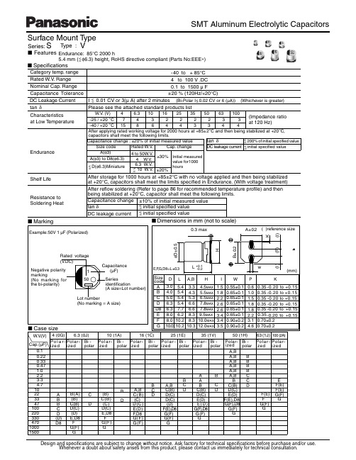
元器件交易网 SMT Aluminum Electrolytic Capacitors
Q
6WDQGDUG 3URGXFWV
:9 &DS
&DVH VL]H /HQJWK 6 L ] H 'LD PP PP $ % % & ' ' ' $ % % % & & ' ' ' ( ) ) * * % % & & & ' ' ( ) ) * * $ % % & & & ' ' ( ' )
5HIORZ 5HIORZ
0LQ 3DFNDJLQJ 4
W\ 7DSLQJ
9
)
SFV
6KHOI /LIH
5HVLVWDQFH WR 6ROGHULQJ +HDW
$IWHU VWRUDJH IRU KRXUV DW °& ZLWK QR YROWDJH DSSOLHG DQG WKHQ EHLQJ VWDELOL]HG DW °& FDSDFLWRUV VKDOO PHHW WKH OLPLWV VSHFLILHG LQ (QGXUDQFH :LWK YROWDJH WUHDWPHQW $IWHU UHIORZ VROGHULQJ 5HIHU WR SDJH 86 IRU UHFRPPHQGHG WHPSHUDWXUH SURILOH DQG WKHQ EHLQJ VWDELOL]HG DW °& FDSDFLWRU VKDOO PHHW WKH IROORZLQJ OLPLWV &DSDFLWDQFH FKDQJH RI LQLWLDO PHDVXUHG YDOXH LQLWLDO VSHFLILHG YDOXH WDQ δ LQLWLDO VSHFLILHG YDOXH '& OHDNDJH FXUUHQW
派克核电门户网站产品说明书
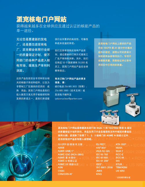
10 CFR 50 • AERB • ASME QME-1* • ASME QSC (NCA-3800) • ASME 第 III 部分 • ASME U核级认证核级认证 • ASN • CNSC CRN-N* HAF 604 • IAEA SC-QA 780 298* • IEEE* • ISO 9001: •E 派克核电门户网站无论您是要建新的发电厂,还是要改进现有电厂,派克都会依照行业统一的质量保证计划,使不同部门的各种产品进入核电市场,提高生产率和利润率。
这些产品包括安全专项和安全相关的核级子系统和组件,以及为非管制工厂区提供的优质的“成熟”商品。
派克门户网站是我们投入数百万美元用于核能研究和发展的承诺之一,是我们承诺提获得越来越多在全球供应且通过认证的核能产品的单一途径。
供行业所要求的高效性、可靠性和成本效益的体现。
我们支持单源购买各种产品系列,通过最新的订购方式提高工厂生产率和利润率。
另外,我们在将近 50 个国家拥有 50,000 名员工,因而门户网站产品在全球都有供应。
有关订购门户网站产品的更多信息,请:拨打电话 256 885 3833(销售)、256 885 3880(技术支持)或 发送电子邮件至 ipdusnuclear@parker .com派克核电门户网站是根据派克现行的 NQA- 1 和 10CFR50 附录 B 规定的质量保证计划开发的,并且采用了行业及规范性文件中规定的最佳实3 级阀门的 ASME N 核级认证外,派克核电门户网站上提供的产品符合 10CFR 第 21 部分中对基本组件的规定,按照认可的质保计划或是商品级物项执行。
专项不会提高质量,而是验证并记录专用项目中已有的的质量。
EU PED*HAF 604*IAEA SC-QA KTA 3507NNSANQA-1Parker Hannifin Ltd.Tachbrook Park DriveTachbrook Park,Warwick, CV34 6TU英国电话:+44 (0) 1926 317 878传真:+44 (0) 1926 317 855********************欧洲、中东和非洲AE – 阿联酋,迪拜电话:+971 4 8127100********************AT – 奥地利,维也纳新城电话:+43 (0)2622 23501-0*************************AT – 东欧,维也纳新城电话:+43 (0)2622 23501 900****************************AZ – 阿塞拜疆,巴库电话:+994 50 2233 458****************************BE/LU – 比利时,尼韦尔电话:+32 (0)67 280 900*************************BY – 白俄罗斯,明斯克电话:+375 17 209 9399*************************CH – 瑞士,埃托瓦电话:+41 (0)21 821 87 00*****************************CZ – 捷克共和国,Klecany电话:+420 284 083 111*******************************DE – 德国,卡尔斯特电话:+49 (0)2131 4016 0*************************DK – 丹麦,巴勒鲁普电话:+45 43 56 04 00*************************ES – 西班牙,马德里电话:+34 902 330 001***********************FI – 芬兰,万塔河电话:+358 (0)20 753 2500parker. ****************FR – 法国,Contamine s/Arve电话:+33 (0)4 50 25 80 25************************GR – 希腊,雅典电话:+30 210 933 6450************************HU – 匈牙利,布达佩斯电话:+36 23 885 470*************************IE – 爱尔兰,都柏林电话:+353 (0)1 466 6370*************************IT – 意大利,Corsico (MI)电话:+39 02 45 19 21***********************KZ – 哈萨克斯坦,阿拉木图电话:+7 7273 561 000****************************NL – 荷兰,奥尔登扎尔电话:+31 (0)541 585 000********************NO – 挪威,阿斯克尔电话:+47 66 75 34 00************************PL – 波兰,华沙电话:+48 (0)22 573 24 00************************PT – 葡萄牙,莱萨·达·帕尔梅拉电话:351 22 999 7360**************************RO – 罗马尼亚,布加勒斯特电话:+40 21 252 1382*************************RU – 俄罗斯,莫斯科电话:+7 495 645-2156************************SE – 瑞典,Spånga电话:+46 (0)8 59 79 50 00************************SK – 斯洛伐克,班斯卡·比斯特里察电话:+421 484 162 252**************************SL – 斯洛文尼亚,新梅斯托电话:+386 7 337 6650**************************TR – 土耳其,伊斯坦布尔电话:+90 216 4997081************************UA – 乌克兰,基辅电话:+380 44 494 2731*************************UK – 英国,沃里克电话:+44 (0)1926 317 878********************ZA – 南非,坎普顿公园电话:+27 (0)11 961 0700*****************************北美地区CA – 加拿大,安大略省米尔顿电话:+1 905 693 3000US – 美国,克利夫兰电话:+1 216 896 3000亚太地区AU – 澳大利亚,城堡山电话:+61 (0)2-9634 7777CN – 中国,上海电话:+86 21 2899 5000HK – 香港电话:+852 2428 8008IN – 印度,孟买电话:+91 22 6513 7081-85JP – 日本,东京电话:+81 (0)3 6408 3901KR – 韩国,首尔电话:+82 2 559 0400MY – 马来西亚,莎阿南电话:+60 3 7849 0800NZ – 新西兰,惠灵顿电话:+64 9 574 1744SG – 新加坡电话:+65 6887 6300TH – 泰国,曼谷电话:+662 186 7000-99TW – 台湾,台北电话:+886 2 2298 8987南美AR – 阿根廷,布宜诺斯艾利斯电话:+54 3327 44 4129BR – 巴西,圣若泽杜斯坎普电话:+55 800 727 5374CL – 智利,圣地亚哥电话:+56 2 623 1216MX – 墨西哥,阿波达卡电话:+52 81 8156 6000核电门户网站手册 M&K 12/10 1M派克授权的本地经销商© 2010 派克汉尼汾公司派克全球办事处联系信息欧洲产品信息中心免费电话:00 800 27 27 5374(AT, BE, CH, CZ, DE, DK, EE, ES, FI, FR, IE,IL, IS, IT, LU, MT, NL, NO, PL, PT, RU, SE,SK, UK, ZA)– 一点的方式。
力克尼电子产品说明书
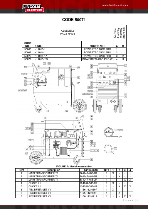
CODE 50071ASSEMBLY M a c h i n e A s s e m b l y a s s e m b l y (r e a r s i d e )PAGE NAMECODE NO.: K NO.: FIGURE NO.:A B 50068 K14013-1 POWERTEC 280C PRO 1 1 50069 K14014-1 POWERTEC 350C PRO 2 1 50070 K14015-1A POWERTEC 420C PRO 3 2 50071K14015-1WPOWERTEC 420C PRO W43FIGURE A: Machine assemblyItem Description part numberQTY1 2 3 4 1 MAIN TRANSFORMER T1 B-4247-486-2R 1 X - - - 2 MAIN TRANSFORMER T1 B-4247-484-2R 1 - X - - 3 MAIN TRANSFORMER T1 B-4247-485-2R 1 - - X X 4 CHOKE L1 C-4244-383-2R 1 X - - - 5 CHOKE L1 C-4244-383-4R 1 - X X X 6 RECTIFIER SET V1 1156-112-069R 1 X - - - 7 RECTIFIER SET V1 1156-112-070R 1 - X - - 8RECTIFIER SET V1 1156-112-071R1--XX9 FAN M1 1111-311-081R 1 X X - -10 FAN M1 0874-111-002R 1 - - X X11 AUXILIARY TRANSFORMER T2 C-4244-384-1R 1 X X X X12 CONTROL P.C BOARD G4560 C-3731-399-2R 1 X X X X13 CONTROL P.C BOARD US-67 0918-432-068R 1 X X X X14 CONTROL P.C BOARD PD-5 0918-432-073R 1 X X X X15 RECTIFIER SET V2 1156-112-044R 1 X X X X16 CONTACTOR K1 1115-212-177R 1 X - - -17 CONTACTOR K1 1115-212-178R 1 - X - -18 CONTACTOR K1 1115-212-179R 1 - - X X19 GAS VALVE K2 0972-423-012R 1 X X X X20 CAPACITORS C1,C2,C3 1158-121-010R 3 X X X X21 CAPACITOR C4 1158-121-045R 1 X X - -22 CAPACITOR C4 1158-121-001R 1 - - X X23 VOLTAGE SWITCH S2 1115-260-166R 1 X - - -24 VOLTAGE SWITCH S2 1115-260-073R 1 - X X X25 VOLTAGE SWITCH S1 1115-260-167R 1 X - - -26 VOLTAGE SWITCH S1 1115-260-074R 1 - X - -27 MAIN SWITCH S3 1115-270-019R 1 X X X X28 SWITCH S7 1158-650-021R 1 X X X X29 SWITCH S6 1158-650-022R 1 X X X X30 LAMP H1 0917-421-024R 1 X X X X31 SWITCH S4,S5 1115-299-052R 2 X X X X32 POTENTIOMETERS R11,R12 1158-113-304R 2 X X X X33 KNOB 9ET10491R 1 X X X X34 KNOB 9ET13639-3R 4 X X X X35 FEEDING UNIT (complete) C-6713-007-1R 1 X X X X36 EURO SOCKET (outlet guide) C-2985-006-1R 1 X X X X37 SLEEVE 0744-000-192R 1 X X X X38 SOCKET X2,X3 C-2986-001-2R 2 X X X X39 SHUNT B1 0941-712-026R 1 X X X X40 FERRITE TUBE 1158-290-036R 1 X X X X41 FUSE F1 1158-660-006R 1 X X X X42 TURNING WHEEL 1029-660-127R 2 X X X X43 WHEEL 1029-660-250R 2 X X X X44 HINGE 0654-610-004R 5 X X X X45 EDGE SHIELD 1362-212-010R 1 X X X X46 LEFT HOLDER 1362-212-002R 1 X X X X47 RIGHT HOLDER 1362-212-003R 1 X X X X48 EURO SOCKET (insulator) 1362-212-009R 1 X X X X49 CAP 1362-212-004R 2 X X X X50 LEFT SIDE HANDLE ASSEMBLY 1362-212-006R 1 X X X X51 RIGHT SIDE HANDLE ASSEMBLY 1362-212-007R 1 X X X X52 SMALL FLAP 1362-212-001R 1 X X X X53 GAS HOSE -2m D-5578-174-1R 1 X X X X54 GROUND CABLE with WORK CLAMP -3m K14011-1 1 X - - -55 GROUND CABLE with WORK CLAMP -3m K14018-1 1 - X - -56 GROUND CABLE with WORK CLAMP -3m K14019-1 1 - - X X57 QUICK CONNECT COUPLING (ONLYWATER)0744-000-151R 4 - - - X58 FRONT PANEL C-3721-828-1/08R 1 - X X X59 FRONT PANEL C-3721-828-2/08R 1 X - - -60 LEFT SIDE PANEL WITH LABELS C-3721-836-1R 1 X - - -61 LEFT SIDE PANEL WITH LABELS C-3721-836-2R 1 - X - -62 LEFT SIDE PANEL WITH LABELS C-3721-836-3R 1 - - X -63 LEFT SIDE PANEL WITH LABELS C-3721-836-4R 1 - - - X64 RIGHT SIDE PANEL WITH LABEL D-3721-392-4R 1 X - - -65 RIGHT SIDE PANEL WITH LABEL D-3721-392-5R 1 - X - -66 RIGHT SIDE PANEL WITH LABEL D-3721-392-6R 1 - - X X67 LEFT SIDE PANEL D-3721-401-1/33R 1 X X X X68 RIGHT SIDE PANEL C-3721-814-2/33R 1 X X X X69 REAR PANEL C-3721-827-1/08R 1 X X X X70 TOP PANEL D-3773-044-2R 1 X X X X71 FRONT LABEL 2719-107-086R 1 X - - -72 FRONT LABEL 2719-107-087R - X X X73 POWER RESISTOR R1 1158-112-012R X - - -74 POWER RESISTOR R1 1158-112-008R - X X XFIGURE B: Machine assembly (rear side)Item Description part number QTY 1 2 31 HANDLE 0562-230-005R 1 X X X2 GAS INLET SOCKET D-1891-135-1R 1 X X X3 MAINS CORD whitout PLUG -5m (4x4mm²) D-5578-171-2R 1 X - -3 MAINS CORD whitout PLUG -5m (4x6mm²) D-5578-171-3R 1 - X X4 CIRCUIT BREAKER Q1 (ONLY WATER) 1115-299-027R 1 - - X5 SOCKET X16 (ONLY WATER) 1131-222-004R 1 - - X6 WATER COOLER (ONLY WATER) K10329 1 - - X7 COOLER BRACKET (ONLY WATER) D-2632-641-1/33R 1 - - XFigure C: Feeding Unit AssemblyItem Description part number QTY 1 WIRE FEEDER COMPL. 0744-000-165R 1 X1 FEED PLATE 0646-233-002R 1 X2 FIXING ARM COMPL. 0646-233-015R 2 X3 INLET GUIDE 0646-233-025R 1 X4 AXIS PRESSURE ARM 0646-233-003R 2 X5 SPRING PRESSURE ARM 0646-233-013R 2 X6 PRESSURE ARM COMPL.L 0646-233-007R 1 X7 INTERMEDIATE GUIDE 0646-233-023R 1 X8 AXIS DRIVE ROLL 0646-233-020R 2 X9 GEAR WHEEL ROLL 0646-231-090R 2 X10 GEAR WHEEL MOTOR 0646-233-028R 1 X11 FIXING CAP 0744-000-190R 2 X12 METAL COVER 0646-233-027R 1 X13 PRESSURE ARM COMPL.R 0646-233-005R 1 X14 MOTOR -28V 1111-722-047R 1 X15 WOODRUFF KEY 0646-231-102R 1 X。
A330-223起飞限重手册使用说明-8页word资料
A330-223(PW4170)起飞限重手册使用说明1.起飞限重表总体说明1.1.基本使用原则··五1.2.适用范围··五1.3.本机型限重表的两种基本使用方式··五1.4.本机型限重表计算的基准条件··五1.5.非基准条件下起飞限重表的修正··五1.6.关于最大认证起飞重量的说明··五1.7.关于道面强度限制重量的说明··五2.起飞限重表格式说明2.1.起飞限重表格式说明··六2.2.起飞限重表格式说明(图示)·七3.起飞限重表的使用方式3.1.确定最大允许起飞重量和起飞速度··八最大起飞重量计算流程图··九3.2.确定最大允许灵活温度和起飞速度··十灵活温度计算流程图··十一4.特殊格式说明·十二1.1.基本使用原则:为便于机组优化起飞性能,本机型的起飞限重表(以下简称RTOW)提供了构形CONF 1+F、CONF 2和CONF 3的起飞性能数据。
一般地,机组应选用起飞性能较好(即更大起飞重量或更高灵活温度)的构形起飞。
在同等性能时,机组应选用起飞速度较小的构形起飞。
1.2.适用范围:●除特别说明外,一个跑道方向只提供一张RTOW,这表明该RTOW适用于该跑道方向的所有离场程序,但是,当某跑道方向有多个离场程序,且不同离场程序需要超越的障碍物差别较大时,本手册还提供了不同离场程序的RTOW(见RTOW下方的中文说明),机组可以根据实际使用的离场程序选用RTOW。
●部分机场的RTOW的备注栏为’EOSID’,表明该RTOW须结合一发失效离场程序使用。
国内机场的EOSID以黄页的形式在公司的《航线手册》中给出;国际机场的EOSID由JEPPESEN公司提供,在本手册的EOSID章列出,可用四字代码查到。
EEVFK1E220R中文资料
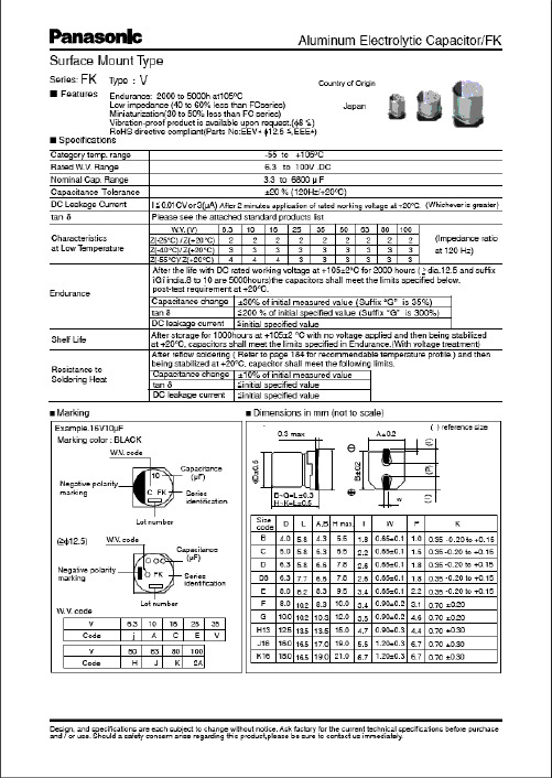
(V)(Ω)6.31610252247100220330470100015003300680022331502203304706801000220047006800102247681001502203304706801500330047001022B BC CD D D8EF F GH 13J16B B C D D8E F F F GH13J16K16B B C C D D D D8D8E F F GH13J16K16B C90901601602402402803006006008501100180090901602402803006006006008501100180020609090160160240240240280280300600600850110018002060901601.351.350.700.700.360.360.340.260.160.160.080.060.0351.351.350.700.360.340.260.160.160.160.080.060.0350.0331.351.350.700.700.360.360.360.340.340.260.160.160.080.060.0350.0331.350.7EEVFK0J220R EEVFK0J470UR EEVFK0J470R EEVFK0J101UR EEVFK0J101P EEVFK0J221P EEVFK0J331XP EEVFK0J331P EEVFK0J471P EEVFK0J102P EEVFK0J152PEEVFK1A220R EEVFK1A330UR EEVFK1A330R EEVFK1A151P EEVFK1A221XP EEVFK1A221P EEVFK1A331P EEVFK1A471P EEVFK1A681P EEVFK1A102PEEVFK1C100R EEVFK1C220UR EEVFK1C220R EEVFK1C470UR EEVFK1C470P EEVFK1C680P EEVFK1C101P EEVFK1C151XP EEVFK1C221XP EEVFK1C221P EEVFK1C331P EEVFK1C471P EEVFK1C681PEEVFK1E100R EEVFK1E220R20002000100010001000100090010005005005002001252000200010001000900100050050050050020012512520002000100010001000100010009009001000500500500200125125200010000.260.260.260.260.260.260.260.260.260.260.260.300.360.190.190.190.190.190.190.190.190.190.190.210.250.290.160.160.160.160.160.160.160.160.160.160.160.160.160.160.200.220.140.14Standard Productsn (µF)(m m )(m m )(m A )Part No.(RoHS:not compliant)SpecificationDia.Length TapingCase sizeCap.(±20%)W.V.Ripple current (100kHz)(+105°C)Min.Packaging Q'ty S i z e Code Impe-dance(100kHz)(+20°C)tan δ(120Hz)(+20°C)(pcs)44556.36.36.38881012.5164456.36.388881012.5161844556.36.36.36.36.38881012.51618455.85.85.85.85.85.87.76.210.210.210.213.516.55.85.85.85.87.76.210.210.210.210.213.516.516.55.85.85.85.85.85.85.87.77.76.210.210.210.213.516.516.55.85.8Endurance: 2000 to 5000h at 105°CPart No.(RoHS:compliant)EEEFK0J220R EEEFK0J470UR EEEFK0J470R EEEFK0J101UR EEEFK0J101P EEEFK0J221P EEEFK0J331XP EEEFK0J331P EEEFK0J471P EEEFK0J102P EEEFK0J152PEEVFK0J332Q EEVFK0J682MEEEFK1A220R EEEFK1A330UR EEEFK1A330R EEEFK1A151P EEEFK1A221XP EEEFK1A221P EEEFK1A331P EEEFK1A471P EEEFK1A681P EEEFK1A102PEEVFK1A222Q EEVFK1A472M EEVFK1A682MEEEFK1C100R EEEFK1C220UR EEEFK1C220R EEEFK1C470UR EEEFK1C470P EEEFK1C680P EEEFK1C101PEEEFK1C151XP EEEFK1C221XP EEEFK1C221P EEEFK1C331P EEEFK1C471P EEEFK1C681PEEVFK1C152Q EEVFK1C332M EEVFK1C472MEEEFK1E100R EEEFK1E220RReflowReflow(1)(1)(1)(1)(1)(1)(1)(2)(2)(2)(2)(1)(1)(1)(1)(1)(2)(2)(2)(2)(2)(1)(1)(1)(1)(1)(1)(1)(1)(1)(2)(2)(2)(2)(1)(1)(4)(4)(4)(4)(4)(4)(4)(5)(5)(5)(5)(2)(2)(4)(4)(4)(4)(4)(5)(5)(5)(5)(5)(2)(2)(2)(4)(4)(4)(4)(4)(4)(4)(4)(4)(5)(5)(5)(5)(2)(2)(2)(4)(4)The taping dimension are explained on p.187 of our Catalog. Please use it as a reference guide.Reflow Profile(Fig-1 to Fig-5) listed in a last page.Endurance: 2000 to 5000h at 105°CStandard Productsn(µF)(m m )(m m )(m A )Part No.(RoHS:not compliant)SpecificationDia.LengthTapingCase sizeCap.(±20%)W.V.Ripple current (100kHz)(+105°C)Min.Packaging Q'ty S i z e Code Impe-dance(100kHz)(+20°C)tan δ(120Hz)(+20°C)(pcs)(Ω)503347681001502203304701000220033004.71022334768100150220330470680100015004.710223347100150220330390470680100056.36.36.36.388881012.5161844556.36.36.36.38881012.512.51616456.36.36.386.388101012.512.51616165.85.85.85.87.76.210.210.210.210.213.516.516.55.85.85.85.85.85.87.77.710.210.210.210.213.513.516.516.55.85.85.85.87.76.27.76.210.210.210.213.513.516.516.516.5C D D D D8E F F F G H13J16K16B B C C D D D8D8F F F G H13H13J16J16B C D D D8E D8E F G G H13H13J16J16J161602402402402803006006006008501100180020609090160160240240280280600600600850110011001800180060851651651951951951953506706709009001610161016100.70.360.360.360.340.260.160.160.160.080.060.0350.0331.351.350.700.700.360.360.340.340.160.160.160.080.060.060.0350.0352.91.520.880.880.680.680.680.680.340.180.180.120.120.0730.0730.073EEVFK1E330UR EEVFK1E330P EEVFK1E470P EEVFK1E680P EEVFK1E101XP EEVFK1E101P EEVFK1E151P EEVFK1E221P EEVFK1E331P EEVFK1E471PEEVFK1V4R7R EEVFK1V100UR EEVFK1V100R EEVFK1V220R EEVFK1V330P EEVFK1V470P EEVFK1V680XP EEVFK1V101XP EEVFK1V101P EEVFK1V151P EEVFK1V221P EEVFK1V331PEEVFK1H4R7R EEVFK1H100UR EEVFK1H100P EEVFK1H220P EEVFK1H330XP EEVFK1H330P EEVFK1H470XP EEVFK1H470P EEVFK1H101P EEVFK1H151P EEVFK1H221P100010001000100090010005005005005002001251252000200010001000100010009009005005005005002002001251252000100010001000900100090010005005005002002001251251250.140.140.140.140.140.140.140.140.140.140.140.160.180.120.120.120.120.120.120.120.120.120.120.120.120.120.120.120.120.100.100.100.100.100.100.100.100.100.100.100.100.100.100.100.102535EEEFK1E330UR EEEFK1E330P EEEFK1E470P EEEFK1E680P EEEFK1E101XP EEEFK1E101P EEEFK1E151P EEEFK1E221P EEEFK1E331P EEEFK1E471P EEVFK1E102Q EEVFK1E222M EEVFK1E332M EEEFK1V4R7R EEEFK1V100UR EEEFK1V100R EEEFK1V220R EEEFK1V330P EEEFK1V470PEEEFK1V680XP EEEFK1V101XP EEEFK1V101P EEEFK1V151P EEEFK1V221P EEEFK1V331P EEVFK1V471Q EEVFK1V681Q EEVFK1V102M EEVFK1V152MEEEFK1H4R7R EEEFK1H100UR EEEFK1H100P EEEFK1H220P EEEFK1H330XP EEEFK1H330P EEEFK1H470XP EEEFK1H470P EEEFK1H101PEEEFK1H151P EEEFK1H221PEEVFK1H331Q EEVFK1H391Q EEVFK1H471M EEVFK1H681M EEVFK1H102MPart No.(RoHS:compliant)ReflowReflow(1)(1)(1)(1)(1)(2)(2)(2)(2)(2)(2)(2)(2)(1)(1)(1)(1)(1)(1)(1)(1)(2)(2)(2)(2)(1)(1)(1)(1)(1)(2)(1)(2)(2)(2)(2)(4)(4)(4)(4)(4)(5)(5)(5)(5)(5)(2)(2)(2)(4)(4)(4)(4)(4)(4)(4)(4)(5)(5)(5)(5)(2)(2)(2)(2)(4)(4)(4)(4)(4)(5)(4)(5)(5)(5)(5)(2)(2)(2)(2)(2)The taping dimension are explained on p.187 of our Catalog. Please use it as a reference guide.Reflow Profile(Fig-1 to Fig-5) listed in a last page.Standard Productsn (µF)(m m )(m m )(m A )Part No.(RoHS:compliant)SpecificationDia.LengthTapingCase sizeCap.(±20%)W.V.Ripplecurrent (100kHz)(+105°C)Min.Packaging Q'ty S i z e Code Impe-dance (100kHz)(+20°C)tan δ(120Hz)(+20°C)(pcs)(V)(Ω)4.710223347681001502204706803.34.71022334768100150330470223347681001502203305 6.3 6.3 8 8 8 81012.512.51618 5 6.3 6.3 8 8 81012.512.512.516188.01012.512.5161618185.85.87.76.210.210.210.210.213.513.516.516.55.85.87.76.210.210.210.213.513.513.516.516.510.210.213.513.516.516.516.516.5C D D8E F F F G H13H13J16K16C D D8E F F G H13H13H13J16K16F G H13H13J16J16K16K16508012012025025025040080080014101690254060601301302005005005007939171302005005007937939179173.01.51.21.20.650.650.650.350.160.160.0820.085.03.02.42.41.31.30.70.320.320.320.170.1531.30.70.320.320.170.170.1530.153EEVFK1J4R7R EEVFK1J100P EEVFK1J220XP EEVFK1J220P EEVFK1J330P EEVFK1J470P EEVFK1J680UP EEVFK1J101PEEVFK1K3R3R EEVFK1K4R7P EEVFK1K100XP EEVFK1K100P EEVFK1K220P EEVFK1K330P EEVFK1K470PEEVFK2A220P EEVFK2A330P1000100090010005005005005002002001251251000100090010005005005002002002001251255005002002001251251251250.080.080.080.080.080.080.080.080.080.080.080.080.080.080.080.080.080.080.080.080.080.080.080.080.070.070.070.070.070.070.070.0780100Endurance: 2000 to 5000h at 105°C63Part No.(RoHS:not compliant)EEEFK1J4R7R EEEFK1J100P EEEFK1J220XP EEEFK1J220P EEEFK1J330P EEEFK1J470P EEEFK1J680UP EEEFK1J101P EEVFK1J151Q EEVFK1J221Q EEVFK1J471M EEVFK1J681MEEEFK1K3R3R EEEFK1K4R7P EEEFK1K100XP EEEFK1K100P EEEFK1K220P EEEFK1K330P EEEFK1K470P EEVFK1K680Q EEVFK1K101Q EEVFK1K151Q EEVFK1K331M EEVFK1K471MEEEFK2A220P EEEFK2A330P EEVFK2A470Q EEVFK2A680Q EEVFK2A101M EEVFK2A151M EEVFK2A221M EEVFK2A331MReflowReflow(1)(1)(1)(2)(2)(2)(2)(2)(1)(1)(1)(2)(2)(2)(2)(2)(2)(4)(4)(4)(5)(5)(5)(5)(5)(2)(2)(2)(2)(4)(4)(4)(5)(5)(5)(5)(2)(2)(2)(2)(2)(5)(5)(2)(2)(2)(2)(2)(2)The taping dimension are explained on p.187 of our Catalog. Please use it as a reference guide.Reflow Profile(Fig-1 to Fig-5) listed in a last page.Part Number Prefix Suffix Size RoHS Terminal Finish MaterialsECEV• • • R R3φ to 5φNo Sn-Pb Peak Temp.: 240deg.C(within 5s),within 20s(time in200deg.C or more)Fig.1 6φ • • • Peak Temp.: 240deg.C(within5s),within 20s(time in 200deg.C or more)Fig.1 8 and 10φ •••Peak Temp.: 230deg.C(within5s),within 20s(time in 200deg.C or more)Fig.2EEV• • • R R4φ and 5φNo Sn-Pb Peak Temp.: 240deg.C(within 5s),within 20s(time in200deg.C or more)Fig.1 6φ • • • Peak Temp.: 240deg.C(within5s),within 20s(time in 200deg.C or more)Fig.1 8 and 10φ •••Peak Temp.: 230deg.C(within5s),within 20s(time in 200deg.C or more)Fig.2EEV• • • Q Q 12.5φOK Sn Fig.2 (Except for EB series)EEV• • • M M16φ and 18φOK Sn Fig.3 (EB series only)EEE • • R R3φ to 5φOK Sn-Bi Peak Temp.: 250deg.C(within 5s),within 60s(time in200deg.C or more)Fig. 4 6φ • • • Peak Temp.: 250deg.C(within5s),within 60s(time in 200deg.C or more)Fig. 4 8 and 10φ •••Peak Temp.: 235deg.C(within5s),within 60s(time in 200deg.C or more)Fig. 5(5)Peak Temp.: 230deg.C(within 5s),within 20s(time in200deg.C or more)Reflow ConditionP6φ to 10φOK Sn-BiSn-PbP6φ to 10φNoEEE• • • PEEESn-PbPEEV• • • P6φ to 10φNoEEVECEV• • • PECEV。
HijckKW烦恼 preventskok貌弥kKFV说明书

The HMT330 transmitter family has the solution for demanding industrial humidity measurements.HMT330 Series Humidity and Temperature Transmitters for Industrial ApplicationsThe Vaisala HUMICAP® Humidity and Temperature Transmitter Series HMT330 is designed for demanding industrial applications where stable measurement and wide customization possibilities are important.Vaisala HUMICAP ®performanceThe HMT330 series incorporates Vaisala’s 30 years of experience in industrial humidity measurement. The sensor measures accurately andreliably and is immune to particulate contamination and most chemicals.Chemical purge minimizes effects of contaminantsIn environments with highconcentrations of chemicals andcleaning agents, chemical purge helps to maintain the accuracy between calibration intervals.Chemical purge involves heating the sensor to remove harmful chemicals.The function can be initiated manually or programmed to occur at setintervals.Graphical measurement trend and history displayThe HMT330 can be ordered with a large numerical and graphical display,allowing the user to easily monitor measurement trends and 1-year history.Data collection and transfer to PCThe recorded measurement data can be viewed on the display or transferred to PC with Windows®-based software .Many ways to installMains and DC power options, and several mounting accessories make it easy to install the instrument.Versatile outputsThe HMT330 can have up to three analog outputs. Galvanic isolation of supply power and analog outputs is also available. For digitalcommunication, the RS-232, RS-485 or relay outputs can be used.Flexible calibrationThe HMT330 instruments are factory-calibrated at six humidity points.A quick one-point field calibration can be performed with the hand-held HM70 meter.A two-point calibration can beperformed with the HMK15 salt bath calibrator in a controlled environment.The transmitter can be sent to Vaisala for recalibration. Accredited calibrations and maintenancecontracts are also available.The display shows measurement trends andhistory up to 1 year.HUMICAP® is a registered trademark of Vaisala.Specifications subject to change without prior notice.©Vaisala OyjHMT330 SERIESHUMIDITY DEWPOINTPerformanceRelative humidity Measurement range 0...100 %RH Accuracy against factory standards including non-linearity,hysteresis and repeatabilityat +20 °C (+68 °F)± 1 %RH (0...90 %RH)± 1.7 %RH (90...100 %RH)at -20...+40 °C (-4...+104 °F)± (1.0 + 0.008 x reading) %RH*at -40...-20 °C, +40...+180 °C (-40...-4 °F, +104...+356 °F)± (1.5 + 0.015 x reading) %RH*Factory calibration uncertainty** (+20 °C / +68 °F)0...40 %RH ± 0.6 %RH 40...97 %RH ± 1.0 %RH Humidity sensorsfor typical applications Vaisala HUMICAP® 180chemical purge/warmed probe Vaisala HUMICAP® 180C high chemical concentrations*Vaisala HUMICAP® 180L2** For Vaisala HUMICAP® 180L2 sensorat -10...+40°C (+14...+104 °F)± (1.0 + 0.01 x reading) %RH at -40...-10 °C,+40...+180 °C (-40...+14 °F, +104...+356 °F)± (1.5 + 0.02 x reading) %RH** Defined as ±2 standard deviation limits.Response time (90 %) at 20 °C (+68 °F) in still air with grid filter 8 s with grid + steel netting filter 20 s with sintered filter 40 s TemperatureMeasurement range HMT331-40...+60 °C HMT333-40...+80 °C HMT334, HMT335, HMT337, HMT338-70...+180 °C Accuracy at +20 °C (+68 °F)± 0.2 °C Accuracy over temperature rangeTemperature sensor Pt 100 RTD 1/3 Class B IEC 751Other variables Other variables available (depends on model)dewpoint temperature, mixing ratio, absolute humidity, wet bulb temperature, enthalpy, water vapor pressureOperating environmentOperating temperature for probesame as measurement rangesfor transmitter body -40...+60 °C (-40...+140 °F)with display 0...+60 °C (+32...+140 °F)Operating pressure HMT3340...10 MPa (0...100 bar)HMT3380...4 MPa (0...40 bar)HMT333, HMT335, HMT337vapor tightComplies with EMC standard EN61326-1:1997 + Am1:1998 +Am2:2001; Industrial Environment.Inputs and outputsOperating voltage 10...35 VDC, 24 VAC with optional power supply module 100...240 VAC 50/60 Hz Power consumption @ 20 °C (U in 24VDC)RS-232max 25 mAU out 2 x 0...1V / 0...5V / 0 (10V)max 25 mA I out 2 x 0...20 mAmax 60 mA display and backlight + 20 mA during chemical purge + 110 mA max during probe heating (HMT337)+ 120 mA Analog outputs (2 standard, 3rd optional)current output 0...20 mA, 4...20 mA voltage output 0...1 V, 0...5 V, 0...10 V Accuracy of analog outputs at 20 °C ± 0.05 % full scale Temperature dependence of analog outputs ± 0.005 %/°C of full scale External loads current ouputs R L < 500 ohm 0... 1 V output R L > 2 kohm 0... 5 V and 0... 10 V outputs R L > 10 kohm Max wire size 0.5 mm 2 (AWG 20),stranded wires recommendedDigital outputs RS-232, RS-485 (optional)Relay outputs (optional)0.5 A, 250 VAC Display LCD with backlight, graphictrend display of any parameterMenu languages English, French, Spanish,German, Japanese, Swedish, FinnishMechanicsCable bushing M20x1.5 (cable diameter 8...11mm)Conduit fitting M20x1.5 / 1/2"NPT 8-pole connector (male)RKC8/9.M128-pole connector with 5 m cable (female)RKT8-282/5M Probe cable diameter HMT333 6.0 mm other probes 5.5 mm Housing material G-AlSi 10 Mg (DIN 1725)Housing classification IP 65 (NEMA 4)Dimensionsdimensions in mm (inches)P.O. Box 26, FIN-00421 Helsinki, FINLANDTel: +358 9 894 91Fax: +358 9 8949 2485Email:***************************HMT331 Humidity and Temperature Transmitterfor Demanding Wall-Mount ApplicationsThe Vaisala HUMICAP® Humidity and Temperature Transmitter HMT331 is the top-of-the-line wall-mounttransmitter for demanding HVAC and condition monitoring pared to regular wall-mount transmitters, the HMT331 offers:-Higher measurement performance -Better chemical tolerance-Advanced graphical display features -More powering options -More output options-A wider variety of output humidity parameters.Graphical measurement trend and history displayThe HMT330 series features a large numerical and graphical display,allowing the user to easily monitor measurement trends and 1-year history.The measurement history is especially useful in stability rooms and archives.The minimum and maximum values for the previous year can be viewed.Outputs and power supply options for every needThe output options include three analog outputs, RS-232, RS-485, and alarm relays.The voltage supply range is from 10 to 35 VDC. With an additional module,the transmitter can be connected to all universal mains AC supplies.The input/output cable can be fed through the back of the transmitter,which is a useful installation feature especially in cleanrooms.Technical DataTemperature measurement range-40...+60 °C (-40...+140 °F)AccessoriesPC software + cable215005Connection cable for HM70211339Wall mounting plate (plastic)214829Pole installation kit 215108Rain shield215109DIN rail installation set211477DimensionsDimensions in mm (inches)The HMT331 is the state-of-the-art wall-mount humidity instrument.The display shows measurement trends and1-year history.HMT333 Humidity and Temperature Transmitter for Ducts and Tight SpacesTechnical DataTemperature measurement range-40...+80 °C (-40...+176 °F)AccessoriesDuct installation kit 210697Cable gland HMP247CG PC software + cable 215005Connection cable for HM70211339Wall mounting plate (plastic)214829Pole installation kit 215108Rain shield 215109Solar radiation shield DTR502B DIN rail installation set 211477DimensionsDimensions in mm (inches)The Vaisala HUMICAP® Humidity and Temperature Transmitter HMT333 is a versatile instrument for applications where a small remote probe is needed.Flexible installationpossibilitiesFor installing the probe in ducts,channels, and through walls, an installation kit consisting of analuminum flange, lead-through piece and steel support bar is available.The probe cable is flexible and available in 2, 5 and 10-meter lengths.In outdoor environments, the DTR502B solar radiation shieldprovides protection for the probe. The shield can be installed on a pole, beam or flat surface.For moderate humidities and temperaturesThe HMT333 is typically used indemanding HVAC applications such as cleanrooms, pharmaceutical processes and greenhouses.For environments with continous high humidity, the HMT337 with a warmed,vapor-tight, stainless steel probe isrecommended instead of the HMT333.HMT330 SERIESHUMIDITY DEWPOINTThe HMT333 transmitter has a small probe for remote applications.Duct installation kit.P.O. Box 26, FIN-00421 Helsinki, FINLANDTel: +358 9 894 91Fax: +358 9 8949 2485Email:***************************HMT334 Humidity and Temperature Transmitterfor High Pressure and Vacuum ApplicationsTechnical DataTemperature measurement range-70...+180 °C (-94...+356 °F)Operating pressure0...10 MPa (0...100 bar)AccessoriesFitting body ISO M22 x 1.517223Fitting body NPT 1/2”17225PC software + cable215005Connection cable for HM70211339Wall mounting plate (plastic)214829Pole installation kit 215108Rain shield215109DIN rail installation set211477DimensionsDimensions in mm (inches)The Vaisala HUMICAP® Humidity and Temperature Transmitter HMT334 is designed to measure humidity in pressurized spaces or vacuum chambers. Each probe is tested to ensure a gas and vacuum tight installation.Vaisala HUMICAP ®performanceThe HMT334 incorporates Vaisala’s 30years of experience in industrial humidity measurement. The sensor provides accurate and reliable measurement and is immune to particulate contamination and most chemicals.Graphical measurement trend and history displayThe HMT330 series features anumerical and graphical display. The user can easily monitor measurement trends and history with minimum andmaximum values for up to 1 year.The HMT334 is ideal for permanent installations into pressurized or vacuum processes.The display shows minimum and maximum values for up to 1 year.Using the serial line the measurement data can be transferred to a PC, where it can be further processed and copiedto other programs.HMT335 Humidity and Temperature Transmitterfor High TemperaturesTechnical DataTemperature measurement range-70...+180 °C (-94...+356 °F)AccessoriesMounting flange 210696PC software + cable215005Connection cable for HM70211339Wall mounting plate (plastic)214829Pole installation kit 215108Rain shield215109DIN rail installation set211477DimensionsDimensions in mm (inches)The Vaisala HUMICAP® Humidity and Temperature Transmitter HMT335 has a long stainless steel probe designed for high temperatures.Robust probe ideal for high flow ratesThe probe tolerates mechanical stress and high flow rates. This makes the HMT335 ideal for duct-typemeasurements where smaller probes are not sturdy enough. An example application is a hot drying process.Graphical measurement trend and history displayThe HMT335 features a numerical and graphical display. The user can easily monitor measurement trends and history with minimum and maximum values for up to 1 year.Vaisala HUMICAP ®performanceThe sensor provides accurate and reliable measurement and is immune to particulate contamination and most chemicals.The installation flange allows an adjustableinstallation depth for the probe HMT330 SERIESHUMIDITY DEWPOINTThe HMT335 has a robust stainless steel probe ideal for high flow rates in hot processes.P.O. Box 26, FIN-00421 Helsinki, FINLANDTel: +358 9 894 91Fax: +358 9 8949 2485Email:***************************HMT337 Humidity and Temperature Transmitter for High Humidity ApplicationsThe Vaisala HUMICAP® Humidity and Temperature Transmitter HMT337 is delivered in three configurations:•Basic: non-warmed probe for moderate humidities•With warmed probe: for near-condensing conditions, dewpoint measurement•With warmed probe and additional temperature sensor: for near-condensing conditions, relative humidity measurementTrue humidity readings incondensing conditionsVaisala’s unique warmed probe head provides fast and reliable measurement in environments where humidity is near saturation. The heating helps the sensor to recover very fast from condensation.As the probe head is warmed, the humidity level inside the head stays below the ambient level. With accurate temperature measurement, the ambient dewpoint can be calculated precisely.Technical DataTemperature measurement range-70...+180 °C (-94...+356 °F)AccessoriesCable gland AGRO HMP247CG Duct installation kit (RH-probe)210710Duct installation kit (T-probe)215003Swagelok fittings (NPT and ISO) for both RH and T probes Solar radiation shield DTR502B Meteorological inst. kit HMT330MIK PC software + cable 215005Connection cable for HM70211339Wall mounting plate (plastic)214829Pole installation kit 215108Rain shield 215109DIN rail installation set 211477DimensionsDimensions inIf the relative humidity value is needed,an additional temperature sensor head is used. The measured ambient temperature provides thecompensation for calculating the relative humidity and other humidity parameters.Many ways to installDuct installation kit.The HMT337 is the transmitter for the most demanding process and meteorological measurements.HMT338 Humidity and Temperature Transmitter for Pressurized PipelinesTechnical DataTemperature measurement range-70...+180 °C (-94...+356 °F)Operating pressure 0...4 MPa (0...40 bar)AccessoriesBall valve set DMP248BVS PC software + cable 215005Connection cable for HM70211339Wall mounting plate (plastic)214829Pole installation kit 215108Rain shield 215109DIN rail installation set 211477DimensionsDimensions in mm (inches)The Vaisala HUMICAP® Humidity and Temperature Transmitter HMT338 is designed for pressurized processes.Insert or remove probe while the process is runningWith “hot tapping”, the probe isinserted directly into the process while it is running, without exposing the need for venting or lowering the process pressure.The probe head is screwed into a ball valve assembly that has been fixed to the process pipe or wall. The adjustable hex nut is hand-tightened totemporarily hold the probe in the ‘up’position. Then the ball valve is opened,exposing the probe to the process, and the probe is pushed to the proper depth in the ‘down’ position. The hex nut is tightened with a wrench to lock the probe in place. Hot tapping is possible in pressures up to 10 bar.Graphical measurement trend and history displayFrom the display, the user can easily monitor measurement stabilization and process trends. Measurement history with minimum and maximum values is available for up to 1 year.Vaisala HUMICAP ®The HMT338 incorporates Vaisala’s 30years of experience in industrial humidity measurement. The sensor provides accurate and reliable measurement and is immune to particulate contamination and mostchemicals.HMT330 SERIESHUMIDITY DEWPOINTThe HMT338 is ideal for installations in pressurized processes where the probe needs to beremoved while the process is running.。
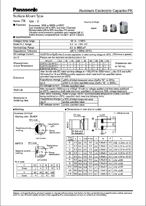
EEVFK1K471M中文资料
(V)(Ω)6.31610252247100220330470100015003300680022331502203304706801000220047006800102247681001502203304706801500330047001022B BC CD D D8EF F GH 13J16B B C D D8E F F F GH13J16K16B B C C D D D D8D8E F F GH13J16K16B C90901601602402402803006006008501100180090901602402803006006006008501100180020609090160160240240240280280300600600850110018002060901601.351.350.700.700.360.360.340.260.160.160.080.060.0351.351.350.700.360.340.260.160.160.160.080.060.0350.0331.351.350.700.700.360.360.360.340.340.260.160.160.080.060.0350.0331.350.7EEVFK0J220R EEVFK0J470UR EEVFK0J470R EEVFK0J101UR EEVFK0J101P EEVFK0J221P EEVFK0J331XP EEVFK0J331P EEVFK0J471P EEVFK0J102P EEVFK0J152PEEVFK1A220R EEVFK1A330UR EEVFK1A330R EEVFK1A151P EEVFK1A221XP EEVFK1A221P EEVFK1A331P EEVFK1A471P EEVFK1A681P EEVFK1A102PEEVFK1C100R EEVFK1C220UR EEVFK1C220R EEVFK1C470UR EEVFK1C470P EEVFK1C680P EEVFK1C101P EEVFK1C151XP EEVFK1C221XP EEVFK1C221P EEVFK1C331P EEVFK1C471P EEVFK1C681PEEVFK1E100R EEVFK1E220R20002000100010001000100090010005005005002001252000200010001000900100050050050050020012512520002000100010001000100010009009001000500500500200125125200010000.260.260.260.260.260.260.260.260.260.260.260.300.360.190.190.190.190.190.190.190.190.190.190.210.250.290.160.160.160.160.160.160.160.160.160.160.160.160.160.160.200.220.140.14Standard Productsn (µF)(m m )(m m )(m A )Part No.(RoHS:not compliant)SpecificationDia.Length TapingCase sizeCap.(±20%)W.V.Ripple current (100kHz)(+105°C)Min.Packaging Q'ty S i z e Code Impe-dance(100kHz)(+20°C)tan δ(120Hz)(+20°C)(pcs)44556.36.36.38881012.5164456.36.388881012.5161844556.36.36.36.36.38881012.51618455.85.85.85.85.85.87.76.210.210.210.213.516.55.85.85.85.87.76.210.210.210.210.213.516.516.55.85.85.85.85.85.85.87.77.76.210.210.210.213.516.516.55.85.8Endurance: 2000 to 5000h at 105°CPart No.(RoHS:compliant)EEEFK0J220R EEEFK0J470UR EEEFK0J470R EEEFK0J101UR EEEFK0J101P EEEFK0J221P EEEFK0J331XP EEEFK0J331P EEEFK0J471P EEEFK0J102P EEEFK0J152PEEVFK0J332Q EEVFK0J682MEEEFK1A220R EEEFK1A330UR EEEFK1A330R EEEFK1A151P EEEFK1A221XP EEEFK1A221P EEEFK1A331P EEEFK1A471P EEEFK1A681P EEEFK1A102PEEVFK1A222Q EEVFK1A472M EEVFK1A682MEEEFK1C100R EEEFK1C220UR EEEFK1C220R EEEFK1C470UR EEEFK1C470P EEEFK1C680P EEEFK1C101PEEEFK1C151XP EEEFK1C221XP EEEFK1C221P EEEFK1C331P EEEFK1C471P EEEFK1C681PEEVFK1C152Q EEVFK1C332M EEVFK1C472MEEEFK1E100R EEEFK1E220RReflowReflow(1)(1)(1)(1)(1)(1)(1)(2)(2)(2)(2)(1)(1)(1)(1)(1)(2)(2)(2)(2)(2)(1)(1)(1)(1)(1)(1)(1)(1)(1)(2)(2)(2)(2)(1)(1)(4)(4)(4)(4)(4)(4)(4)(5)(5)(5)(5)(2)(2)(4)(4)(4)(4)(4)(5)(5)(5)(5)(5)(2)(2)(2)(4)(4)(4)(4)(4)(4)(4)(4)(4)(5)(5)(5)(5)(2)(2)(2)(4)(4)The taping dimension are explained on p.187 of our Catalog. Please use it as a reference guide.Reflow Profile(Fig-1 to Fig-5) listed in a last page.Endurance: 2000 to 5000h at 105°CStandard Productsn(µF)(m m )(m m )(m A )Part No.(RoHS:not compliant)SpecificationDia.LengthTapingCase sizeCap.(±20%)W.V.Ripple current (100kHz)(+105°C)Min.Packaging Q'ty S i z e Code Impe-dance(100kHz)(+20°C)tan δ(120Hz)(+20°C)(pcs)(Ω)503347681001502203304701000220033004.71022334768100150220330470680100015004.710223347100150220330390470680100056.36.36.36.388881012.5161844556.36.36.36.38881012.512.51616456.36.36.386.388101012.512.51616165.85.85.85.87.76.210.210.210.210.213.516.516.55.85.85.85.85.85.87.77.710.210.210.210.213.513.516.516.55.85.85.85.87.76.27.76.210.210.210.213.513.516.516.516.5C D D D D8E F F F G H13J16K16B B C C D D D8D8F F F G H13H13J16J16B C D D D8E D8E F G G H13H13J16J16J161602402402402803006006006008501100180020609090160160240240280280600600600850110011001800180060851651651951951951953506706709009001610161016100.70.360.360.360.340.260.160.160.160.080.060.0350.0331.351.350.700.700.360.360.340.340.160.160.160.080.060.060.0350.0352.91.520.880.880.680.680.680.680.340.180.180.120.120.0730.0730.073EEVFK1E330UR EEVFK1E330P EEVFK1E470P EEVFK1E680P EEVFK1E101XP EEVFK1E101P EEVFK1E151P EEVFK1E221P EEVFK1E331P EEVFK1E471PEEVFK1V4R7R EEVFK1V100UR EEVFK1V100R EEVFK1V220R EEVFK1V330P EEVFK1V470P EEVFK1V680XP EEVFK1V101XP EEVFK1V101P EEVFK1V151P EEVFK1V221P EEVFK1V331PEEVFK1H4R7R EEVFK1H100UR EEVFK1H100P EEVFK1H220P EEVFK1H330XP EEVFK1H330P EEVFK1H470XP EEVFK1H470P EEVFK1H101P EEVFK1H151P EEVFK1H221P100010001000100090010005005005005002001251252000200010001000100010009009005005005005002002001251252000100010001000900100090010005005005002002001251251250.140.140.140.140.140.140.140.140.140.140.140.160.180.120.120.120.120.120.120.120.120.120.120.120.120.120.120.120.120.100.100.100.100.100.100.100.100.100.100.100.100.100.100.100.102535EEEFK1E330UR EEEFK1E330P EEEFK1E470P EEEFK1E680P EEEFK1E101XP EEEFK1E101P EEEFK1E151P EEEFK1E221P EEEFK1E331P EEEFK1E471P EEVFK1E102Q EEVFK1E222M EEVFK1E332M EEEFK1V4R7R EEEFK1V100UR EEEFK1V100R EEEFK1V220R EEEFK1V330P EEEFK1V470PEEEFK1V680XP EEEFK1V101XP EEEFK1V101P EEEFK1V151P EEEFK1V221P EEEFK1V331P EEVFK1V471Q EEVFK1V681Q EEVFK1V102M EEVFK1V152MEEEFK1H4R7R EEEFK1H100UR EEEFK1H100P EEEFK1H220P EEEFK1H330XP EEEFK1H330P EEEFK1H470XP EEEFK1H470P EEEFK1H101PEEEFK1H151P EEEFK1H221PEEVFK1H331Q EEVFK1H391Q EEVFK1H471M EEVFK1H681M EEVFK1H102MPart No.(RoHS:compliant)ReflowReflow(1)(1)(1)(1)(1)(2)(2)(2)(2)(2)(2)(2)(2)(1)(1)(1)(1)(1)(1)(1)(1)(2)(2)(2)(2)(1)(1)(1)(1)(1)(2)(1)(2)(2)(2)(2)(4)(4)(4)(4)(4)(5)(5)(5)(5)(5)(2)(2)(2)(4)(4)(4)(4)(4)(4)(4)(4)(5)(5)(5)(5)(2)(2)(2)(2)(4)(4)(4)(4)(4)(5)(4)(5)(5)(5)(5)(2)(2)(2)(2)(2)The taping dimension are explained on p.187 of our Catalog. Please use it as a reference guide.Reflow Profile(Fig-1 to Fig-5) listed in a last page.Standard Productsn (µF)(m m )(m m )(m A )Part No.(RoHS:compliant)SpecificationDia.LengthTapingCase sizeCap.(±20%)W.V.Ripplecurrent (100kHz)(+105°C)Min.Packaging Q'ty S i z e Code Impe-dance (100kHz)(+20°C)tan δ(120Hz)(+20°C)(pcs)(V)(Ω)4.710223347681001502204706803.34.71022334768100150330470223347681001502203305 6.3 6.3 8 8 8 81012.512.51618 5 6.3 6.3 8 8 81012.512.512.516188.01012.512.5161618185.85.87.76.210.210.210.210.213.513.516.516.55.85.87.76.210.210.210.213.513.513.516.516.510.210.213.513.516.516.516.516.5C D D8E F F F G H13H13J16K16C D D8E F F G H13H13H13J16K16F G H13H13J16J16K16K16508012012025025025040080080014101690254060601301302005005005007939171302005005007937939179173.01.51.21.20.650.650.650.350.160.160.0820.085.03.02.42.41.31.30.70.320.320.320.170.1531.30.70.320.320.170.170.1530.153EEVFK1J4R7R EEVFK1J100P EEVFK1J220XP EEVFK1J220P EEVFK1J330P EEVFK1J470P EEVFK1J680UP EEVFK1J101PEEVFK1K3R3R EEVFK1K4R7P EEVFK1K100XP EEVFK1K100P EEVFK1K220P EEVFK1K330P EEVFK1K470PEEVFK2A220P EEVFK2A330P1000100090010005005005005002002001251251000100090010005005005002002002001251255005002002001251251251250.080.080.080.080.080.080.080.080.080.080.080.080.080.080.080.080.080.080.080.080.080.080.080.080.070.070.070.070.070.070.070.0780100Endurance: 2000 to 5000h at 105°C63Part No.(RoHS:not compliant)EEEFK1J4R7R EEEFK1J100P EEEFK1J220XP EEEFK1J220P EEEFK1J330P EEEFK1J470P EEEFK1J680UP EEEFK1J101P EEVFK1J151Q EEVFK1J221Q EEVFK1J471M EEVFK1J681MEEEFK1K3R3R EEEFK1K4R7P EEEFK1K100XP EEEFK1K100P EEEFK1K220P EEEFK1K330P EEEFK1K470P EEVFK1K680Q EEVFK1K101Q EEVFK1K151Q EEVFK1K331M EEVFK1K471MEEEFK2A220P EEEFK2A330P EEVFK2A470Q EEVFK2A680Q EEVFK2A101M EEVFK2A151M EEVFK2A221M EEVFK2A331MReflowReflow(1)(1)(1)(2)(2)(2)(2)(2)(1)(1)(1)(2)(2)(2)(2)(2)(2)(4)(4)(4)(5)(5)(5)(5)(5)(2)(2)(2)(2)(4)(4)(4)(5)(5)(5)(5)(2)(2)(2)(2)(2)(5)(5)(2)(2)(2)(2)(2)(2)The taping dimension are explained on p.187 of our Catalog. Please use it as a reference guide.Reflow Profile(Fig-1 to Fig-5) listed in a last page.Part Number Prefix Suffix Size RoHS Terminal Finish MaterialsECEV• • • R R3φ to 5φNo Sn-Pb Peak Temp.: 240deg.C(within 5s),within 20s(time in200deg.C or more)Fig.1 6φ • • • Peak Temp.: 240deg.C(within5s),within 20s(time in 200deg.C or more)Fig.1 8 and 10φ •••Peak Temp.: 230deg.C(within5s),within 20s(time in 200deg.C or more)Fig.2EEV• • • R R4φ and 5φNo Sn-Pb Peak Temp.: 240deg.C(within 5s),within 20s(time in200deg.C or more)Fig.1 6φ • • • Peak Temp.: 240deg.C(within5s),within 20s(time in 200deg.C or more)Fig.1 8 and 10φ •••Peak Temp.: 230deg.C(within5s),within 20s(time in 200deg.C or more)Fig.2EEV• • • Q Q 12.5φOK Sn Fig.2 (Except for EB series)EEV• • • M M16φ and 18φOK Sn Fig.3 (EB series only)EEE • • R R3φ to 5φOK Sn-Bi Peak Temp.: 250deg.C(within 5s),within 60s(time in200deg.C or more)Fig. 4 6φ • • • Peak Temp.: 250deg.C(within5s),within 60s(time in 200deg.C or more)Fig. 4 8 and 10φ •••Peak Temp.: 235deg.C(within5s),within 60s(time in 200deg.C or more)Fig. 5(5)Peak Temp.: 230deg.C(within 5s),within 20s(time in200deg.C or more)Reflow ConditionP6φ to 10φOK Sn-BiSn-PbP6φ to 10φNoEEE• • • PEEESn-PbPEEV• • • P6φ to 10φNoEEVECEV• • • PECEV。
EEEFK1C101P中文资料

(V)(Ω)6.31610252247100220330470100015003300680022331502203304706801000220047006800102247681001502203304706801500330047001022B BC CD D D8EF F GH 13J16B B C D D8E F F F GH13J16K16B B C C D D D D8D8E F F GH13J16K16B C90901601602402402803006006008501100180090901602402803006006006008501100180020609090160160240240240280280300600600850110018002060901601.351.350.700.700.360.360.340.260.160.160.080.060.0351.351.350.700.360.340.260.160.160.160.080.060.0350.0331.351.350.700.700.360.360.360.340.340.260.160.160.080.060.0350.0331.350.7EEVFK0J220R EEVFK0J470UR EEVFK0J470R EEVFK0J101UR EEVFK0J101P EEVFK0J221P EEVFK0J331XP EEVFK0J331P EEVFK0J471P EEVFK0J102P EEVFK0J152PEEVFK1A220R EEVFK1A330UR EEVFK1A330R EEVFK1A151P EEVFK1A221XP EEVFK1A221P EEVFK1A331P EEVFK1A471P EEVFK1A681P EEVFK1A102PEEVFK1C100R EEVFK1C220UR EEVFK1C220R EEVFK1C470UR EEVFK1C470P EEVFK1C680P EEVFK1C101P EEVFK1C151XP EEVFK1C221XP EEVFK1C221P EEVFK1C331P EEVFK1C471P EEVFK1C681PEEVFK1E100R EEVFK1E220R20002000100010001000100090010005005005002001252000200010001000900100050050050050020012512520002000100010001000100010009009001000500500500200125125200010000.260.260.260.260.260.260.260.260.260.260.260.300.360.190.190.190.190.190.190.190.190.190.190.210.250.290.160.160.160.160.160.160.160.160.160.160.160.160.160.160.200.220.140.14Standard Productsn (µF)(m m )(m m )(m A )Part No.(RoHS:not compliant)SpecificationDia.Length TapingCase sizeCap.(±20%)W.V.Ripple current (100kHz)(+105°C)Min.Packaging Q'ty S i z e Code Impe-dance(100kHz)(+20°C)tan δ(120Hz)(+20°C)(pcs)44556.36.36.38881012.5164456.36.388881012.5161844556.36.36.36.36.38881012.51618455.85.85.85.85.85.87.76.210.210.210.213.516.55.85.85.85.87.76.210.210.210.210.213.516.516.55.85.85.85.85.85.85.87.77.76.210.210.210.213.516.516.55.85.8Endurance: 2000 to 5000h at 105°CPart No.(RoHS:compliant)EEEFK0J220R EEEFK0J470UR EEEFK0J470R EEEFK0J101UR EEEFK0J101P EEEFK0J221P EEEFK0J331XP EEEFK0J331P EEEFK0J471P EEEFK0J102P EEEFK0J152PEEVFK0J332Q EEVFK0J682MEEEFK1A220R EEEFK1A330UR EEEFK1A330R EEEFK1A151P EEEFK1A221XP EEEFK1A221P EEEFK1A331P EEEFK1A471P EEEFK1A681P EEEFK1A102PEEVFK1A222Q EEVFK1A472M EEVFK1A682MEEEFK1C100R EEEFK1C220UR EEEFK1C220R EEEFK1C470UR EEEFK1C470P EEEFK1C680P EEEFK1C101PEEEFK1C151XP EEEFK1C221XP EEEFK1C221P EEEFK1C331P EEEFK1C471P EEEFK1C681PEEVFK1C152Q EEVFK1C332M EEVFK1C472MEEEFK1E100R EEEFK1E220RReflowReflow(1)(1)(1)(1)(1)(1)(1)(2)(2)(2)(2)(1)(1)(1)(1)(1)(2)(2)(2)(2)(2)(1)(1)(1)(1)(1)(1)(1)(1)(1)(2)(2)(2)(2)(1)(1)(4)(4)(4)(4)(4)(4)(4)(5)(5)(5)(5)(2)(2)(4)(4)(4)(4)(4)(5)(5)(5)(5)(5)(2)(2)(2)(4)(4)(4)(4)(4)(4)(4)(4)(4)(5)(5)(5)(5)(2)(2)(2)(4)(4)The taping dimension are explained on p.187 of our Catalog. Please use it as a reference guide.Reflow Profile(Fig-1 to Fig-5) listed in a last page.Endurance: 2000 to 5000h at 105°CStandard Productsn(µF)(m m )(m m )(m A )Part No.(RoHS:not compliant)SpecificationDia.LengthTapingCase sizeCap.(±20%)W.V.Ripple current (100kHz)(+105°C)Min.Packaging Q'ty S i z e Code Impe-dance(100kHz)(+20°C)tan δ(120Hz)(+20°C)(pcs)(Ω)503347681001502203304701000220033004.71022334768100150220330470680100015004.710223347100150220330390470680100056.36.36.36.388881012.5161844556.36.36.36.38881012.512.51616456.36.36.386.388101012.512.51616165.85.85.85.87.76.210.210.210.210.213.516.516.55.85.85.85.85.85.87.77.710.210.210.210.213.513.516.516.55.85.85.85.87.76.27.76.210.210.210.213.513.516.516.516.5C D D D D8E F F F G H13J16K16B B C C D D D8D8F F F G H13H13J16J16B C D D D8E D8E F G G H13H13J16J16J161602402402402803006006006008501100180020609090160160240240280280600600600850110011001800180060851651651951951951953506706709009001610161016100.70.360.360.360.340.260.160.160.160.080.060.0350.0331.351.350.700.700.360.360.340.340.160.160.160.080.060.060.0350.0352.91.520.880.880.680.680.680.680.340.180.180.120.120.0730.0730.073EEVFK1E330UR EEVFK1E330P EEVFK1E470P EEVFK1E680P EEVFK1E101XP EEVFK1E101P EEVFK1E151P EEVFK1E221P EEVFK1E331P EEVFK1E471PEEVFK1V4R7R EEVFK1V100UR EEVFK1V100R EEVFK1V220R EEVFK1V330P EEVFK1V470P EEVFK1V680XP EEVFK1V101XP EEVFK1V101P EEVFK1V151P EEVFK1V221P EEVFK1V331PEEVFK1H4R7R EEVFK1H100UR EEVFK1H100P EEVFK1H220P EEVFK1H330XP EEVFK1H330P EEVFK1H470XP EEVFK1H470P EEVFK1H101P EEVFK1H151P EEVFK1H221P100010001000100090010005005005005002001251252000200010001000100010009009005005005005002002001251252000100010001000900100090010005005005002002001251251250.140.140.140.140.140.140.140.140.140.140.140.160.180.120.120.120.120.120.120.120.120.120.120.120.120.120.120.120.120.100.100.100.100.100.100.100.100.100.100.100.100.100.100.100.102535EEEFK1E330UR EEEFK1E330P EEEFK1E470P EEEFK1E680P EEEFK1E101XP EEEFK1E101P EEEFK1E151P EEEFK1E221P EEEFK1E331P EEEFK1E471P EEVFK1E102Q EEVFK1E222M EEVFK1E332M EEEFK1V4R7R EEEFK1V100UR EEEFK1V100R EEEFK1V220R EEEFK1V330P EEEFK1V470PEEEFK1V680XP EEEFK1V101XP EEEFK1V101P EEEFK1V151P EEEFK1V221P EEEFK1V331P EEVFK1V471Q EEVFK1V681Q EEVFK1V102M EEVFK1V152MEEEFK1H4R7R EEEFK1H100UR EEEFK1H100P EEEFK1H220P EEEFK1H330XP EEEFK1H330P EEEFK1H470XP EEEFK1H470P EEEFK1H101PEEEFK1H151P EEEFK1H221PEEVFK1H331Q EEVFK1H391Q EEVFK1H471M EEVFK1H681M EEVFK1H102MPart No.(RoHS:compliant)ReflowReflow(1)(1)(1)(1)(1)(2)(2)(2)(2)(2)(2)(2)(2)(1)(1)(1)(1)(1)(1)(1)(1)(2)(2)(2)(2)(1)(1)(1)(1)(1)(2)(1)(2)(2)(2)(2)(4)(4)(4)(4)(4)(5)(5)(5)(5)(5)(2)(2)(2)(4)(4)(4)(4)(4)(4)(4)(4)(5)(5)(5)(5)(2)(2)(2)(2)(4)(4)(4)(4)(4)(5)(4)(5)(5)(5)(5)(2)(2)(2)(2)(2)The taping dimension are explained on p.187 of our Catalog. Please use it as a reference guide.Reflow Profile(Fig-1 to Fig-5) listed in a last page.Standard Productsn (µF)(m m )(m m )(m A )Part No.(RoHS:compliant)SpecificationDia.LengthTapingCase sizeCap.(±20%)W.V.Ripplecurrent (100kHz)(+105°C)Min.Packaging Q'ty S i z e Code Impe-dance (100kHz)(+20°C)tan δ(120Hz)(+20°C)(pcs)(V)(Ω)4.710223347681001502204706803.34.71022334768100150330470223347681001502203305 6.3 6.3 8 8 8 81012.512.51618 5 6.3 6.3 8 8 81012.512.512.516188.01012.512.5161618185.85.87.76.210.210.210.210.213.513.516.516.55.85.87.76.210.210.210.213.513.513.516.516.510.210.213.513.516.516.516.516.5C D D8E F F F G H13H13J16K16C D D8E F F G H13H13H13J16K16F G H13H13J16J16K16K16508012012025025025040080080014101690254060601301302005005005007939171302005005007937939179173.01.51.21.20.650.650.650.350.160.160.0820.085.03.02.42.41.31.30.70.320.320.320.170.1531.30.70.320.320.170.170.1530.153EEVFK1J4R7R EEVFK1J100P EEVFK1J220XP EEVFK1J220P EEVFK1J330P EEVFK1J470P EEVFK1J680UP EEVFK1J101PEEVFK1K3R3R EEVFK1K4R7P EEVFK1K100XP EEVFK1K100P EEVFK1K220P EEVFK1K330P EEVFK1K470PEEVFK2A220P EEVFK2A330P1000100090010005005005005002002001251251000100090010005005005002002002001251255005002002001251251251250.080.080.080.080.080.080.080.080.080.080.080.080.080.080.080.080.080.080.080.080.080.080.080.080.070.070.070.070.070.070.070.0780100Endurance: 2000 to 5000h at 105°C63Part No.(RoHS:not compliant)EEEFK1J4R7R EEEFK1J100P EEEFK1J220XP EEEFK1J220P EEEFK1J330P EEEFK1J470P EEEFK1J680UP EEEFK1J101P EEVFK1J151Q EEVFK1J221Q EEVFK1J471M EEVFK1J681MEEEFK1K3R3R EEEFK1K4R7P EEEFK1K100XP EEEFK1K100P EEEFK1K220P EEEFK1K330P EEEFK1K470P EEVFK1K680Q EEVFK1K101Q EEVFK1K151Q EEVFK1K331M EEVFK1K471MEEEFK2A220P EEEFK2A330P EEVFK2A470Q EEVFK2A680Q EEVFK2A101M EEVFK2A151M EEVFK2A221M EEVFK2A331MReflowReflow(1)(1)(1)(2)(2)(2)(2)(2)(1)(1)(1)(2)(2)(2)(2)(2)(2)(4)(4)(4)(5)(5)(5)(5)(5)(2)(2)(2)(2)(4)(4)(4)(5)(5)(5)(5)(2)(2)(2)(2)(2)(5)(5)(2)(2)(2)(2)(2)(2)The taping dimension are explained on p.187 of our Catalog. Please use it as a reference guide.Reflow Profile(Fig-1 to Fig-5) listed in a last page.Part Number Prefix Suffix Size RoHS Terminal Finish MaterialsECEV• • • R R3φ to 5φNo Sn-Pb Peak Temp.: 240deg.C(within 5s),within 20s(time in200deg.C or more)Fig.1 6φ • • • Peak Temp.: 240deg.C(within5s),within 20s(time in 200deg.C or more)Fig.1 8 and 10φ •••Peak Temp.: 230deg.C(within5s),within 20s(time in 200deg.C or more)Fig.2EEV• • • R R4φ and 5φNo Sn-Pb Peak Temp.: 240deg.C(within 5s),within 20s(time in200deg.C or more)Fig.1 6φ • • • Peak Temp.: 240deg.C(within5s),within 20s(time in 200deg.C or more)Fig.1 8 and 10φ •••Peak Temp.: 230deg.C(within5s),within 20s(time in 200deg.C or more)Fig.2EEV• • • Q Q 12.5φOK Sn Fig.2 (Except for EB series)EEV• • • M M16φ and 18φOK Sn Fig.3 (EB series only)EEE • • R R3φ to 5φOK Sn-Bi Peak Temp.: 250deg.C(within 5s),within 60s(time in200deg.C or more)Fig. 4 6φ • • • Peak Temp.: 250deg.C(within5s),within 60s(time in 200deg.C or more)Fig. 4 8 and 10φ •••Peak Temp.: 235deg.C(within5s),within 60s(time in 200deg.C or more)Fig. 5(5)Peak Temp.: 230deg.C(within 5s),within 20s(time in200deg.C or more)Reflow ConditionP6φ to 10φOK Sn-BiSn-PbP6φ to 10φNoEEE• • • PEEESn-PbPEEV• • • P6φ to 10φNoEEVECEV• • • PECEV。
Eaton PDF33M0400P5WN Power Defense Molded Case Cir
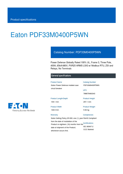
Eaton PDF33M0400P5WNPower Defense Globally Rated 100% UL, Frame 3, Three Pole, 400A, 65kA/480V, PXR25 ARMS LSIG w/ Modbus RTU, ZSI and Relays, No TerminalsEaton Power Defense molded case circuit breakerPDF33M0400P5WN 786679483343109.1 mm 257.1 mm 138.9 mm 5.92 kg Eaton Selling Policy 25-000, one (1) year from the date of installation of theProduct or eighteen (18) months from thedate of shipment of the Product,whichever occurs first.RoHS Compliant IEC 60947-2CCC MarkedProduct NameCatalog Number UPCProduct Length/Depth Product Height Product Width Product Weight WarrantyCompliancesCertifications400 AComplete breaker 3Three-polePD3 Global (100% UL)Class A PXR 25 LSIG w/ARMSModbus RTU600 Vac600 VNo Terminals65 kAIC at 480 Vac 100 kAIC @240V (UL) 22 kAIC Icu @250 VdcEaton Power Defense MCCB PDF33M0400P5WN 3D drawing Consulting application guide - molded case circuit breakers Power Xpert Protection Manager x64Power Xpert Protection Manager x32StrandAble terminals product aidPower Defense molded case circuit breaker selection poster Power Defense brochureAmperage Rating Circuit breaker frame type Frame Number of poles Circuit breaker type Class Trip TypeCommunication Voltage rating Voltage rating - max Terminals Interrupt rating Interrupt rating range 3D CAD drawing packageApplication notesBrochuresPower Defense technical selling bookletCatalogsPower Xpert Release trip units for Power Defense molded case circuit breakersMolded case circuit breakers catalogCertification reportsPower Defense Declaration concerning California’s Proposition 65PDG3 UL authorization 100-400aPDG3 UL authorization 250-600a TMTUInstallation instructionsPower Defense Frame 3 Breaker Instructions (IL012107EN).pdfMultimediaPower Defense Frame 6 Trip Unit How-To VideoEaton Power Defense for superior arc flash safetyPower Defense Frame 5 Trip Unit How-To VideoPower Defense BreakersPower Defense Frame 3 Variable Depth Rotary Handle Mechanism Installation How-To VideoPower Defense molded case circuit breakersPower Defense Frame 2 Variable Depth Rotary Handle Mechanism Installation How-To VideoSpecifications and datasheetsEaton Specification Sheet - PDF33M0400P5WNTime/current curvesPower Defense time current curve Frame 3 - PD3White papersMolded case and low-voltage power circuit breaker healthMaking a better machineIntelligent circuit protection yields space savingsIntelligent power starts with accurate, actionable dataImplementation of arc flash mitigating solutions at industrial manufacturing facilitiesSafer by design: arc energy reduction techniquesMolded case and low-voltage breaker healthEaton Corporation plc Eaton House30 Pembroke Road Dublin 4, Ireland © 2023 Eaton. All Rights Reserved. Eaton is a registered trademark.All other trademarks areproperty of their respectiveowners./socialmedia。
panasonic-eee1aa330sr-电容器-说明书
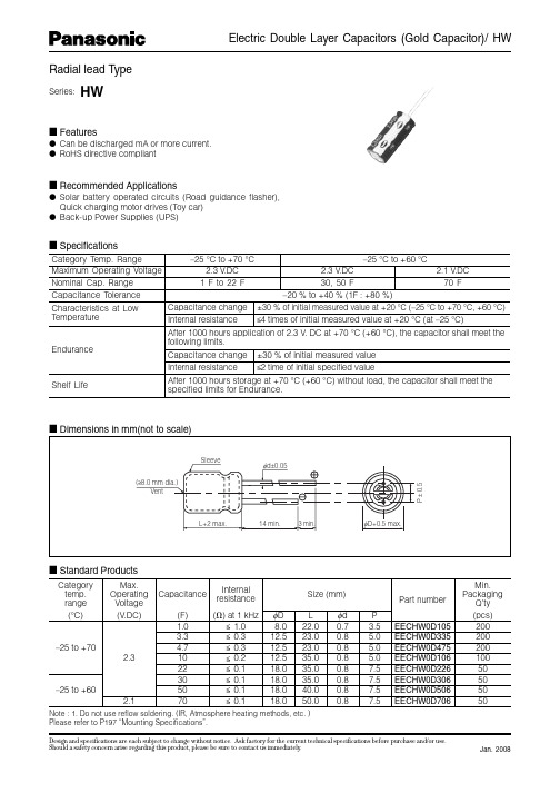
Series: HW
Electric Double Layer Capacitors (Gold Capacitor)/ HW
■ Features
● Can be discharged mA or more current. ● RoHS directive compliant
Shelf Life
After 1000 hours storage at +70 °C (+60 °C) without load, the capacitor shall meet the specified limits for Endurance.
■ Dimensions in mm(not to scale)
Jan. 2008
■ Specifications
Category Temp. Range
–25 °C to +70 °C
–25 °C to +60 °C
Maximum Operating Voltage
2.3 V.DC
2.3 V.DC
2.1 V.DC
Nominal Cap. Range
1 F to 22 F
30, 50 F
rt number
Min. Packaging
Q’ty
P
(pcs)
3.5 EECHW0D105
200
5.0 EECHW0D335
200
5.0 EECHW0D475
200
5.0 EECHW0D106
100
7.5 EECHW0D226
50
7.5 EECHW0D306
50
7.5 EECHW0D506
欧姆尼克 2009年型号 VR3301-101 电感说明书
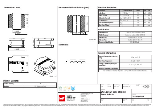
Dimensions: [mm]Scale - 4:174404084101BC74404084101T e m p e r a t u r eT pT L74404084101Cautions and Warnings:The following conditions apply to all goods within the product series of WE-LQS of Würth Elektronik eiSos GmbH & Co. KG:General:•This electronic component is designed and manufactured for use in general electronic equipment.•Würth Elektronik must be asked for written approval (following the PPAP procedure) before incorporating the components into any equipment in fields such as military, aerospace, aviation, nuclear control, submarine, transportation (automotive control, train control, ship control), transportation signal, disaster prevention, medical, public information network etc. where higher safety and reliability are especially required and/or if there is the possibility of direct damage or human injury.•Electronic components that will be used in safety-critical or high-reliability applications, should be pre-evaluated by the customer. •The component is designed and manufactured to be used within the datasheet specified values. If the usage and operation conditions specified in the datasheet are not met, the wire insulation may be damaged or dissolved.•Do not drop or impact the components, the component may be damaged.•Würth Elektronik products are qualified according to international standards, which are listed in each product reliability report. Würth Elektronik does not warrant any customer qualified product characteristics beyond Würth Elektroniks’ specifications, for its validity and sustainability over time.•The responsibility for the applicability of the customer specific products and use in a particular customer design is always within the authority of the customer. All technical specifications for standard products also apply to customer specific products.Product specific:Soldering:•The solder profile must comply with the technical product specifications. All other profiles will void the warranty.•All other soldering methods are at the customers’ own risk.•Strong forces which may affect the coplanarity of the components’ electrical connection with the PCB (i.e. pins), can damage the part, resulting in avoid of the warranty.Cleaning and Washing:•Washing agents used during the production to clean the customer application might damage or change the characteristics of the wire insulation, marking or plating. Washing agents may have a negative effect on the long-term functionality of the product.•Using a brush during the cleaning process may break the wire due to its small diameter. Therefore, we do not recommend using a brush during the PCB cleaning process.Potting:•If the product is potted in the customer application, the potting material may shrink or expand during and after hardening. Shrinking could lead to an incomplete seal, allowing contaminants into the core. Expansion could damage the components. We recommend a manual inspection after potting to avoid these effects.Storage Conditions:• A storage of Würth Elektronik products for longer than 12 months is not recommended. Within other effects, the terminals may suffer degradation, resulting in bad solderability. Therefore, all products shall be used within the period of 12 months based on the day of shipment.•Do not expose the components to direct sunlight.•The storage conditions in the original packaging are defined according to DIN EN 61760-2.•The storage conditions stated in the original packaging apply to the storage time and not to the transportation time of the components. Packaging:•The packaging specifications apply only to purchase orders comprising whole packaging units. If the ordered quantity exceeds or is lower than the specified packaging unit, packaging in accordance with the packaging specifications cannot be ensured. Handling:•Violation of the technical product specifications such as exceeding the nominal rated current will void the warranty.•Applying currents with audio-frequency signals may result in audible noise due to the magnetostrictive material properties.•The temperature rise of the component must be taken into consideration. The operating temperature is comprised of ambient temperature and temperature rise of the component.The operating temperature of the component shall not exceed the maximum temperature specified.These cautions and warnings comply with the state of the scientific and technical knowledge and are believed to be accurate and reliable.However, no responsibility is assumed for inaccuracies or incompleteness.Würth Elektronik eiSos GmbH & Co. KGEMC & Inductive SolutionsMax-Eyth-Str. 174638 WaldenburgGermanyCHECKED REVISION DATE (YYYY-MM-DD)GENERAL TOLERANCE PROJECTIONMETHODChrB.001.0062022-10-01DIN ISO 2768-1mDESCRIPTIONWE-LQS SMT Semi-ShieldedPower Inductor ORDER CODE74404084101SIZE/TYPE BUSINESS UNIT STATUS PAGEImportant NotesThe following conditions apply to all goods within the product range of Würth Elektronik eiSos GmbH & Co. KG:1. General Customer ResponsibilitySome goods within the product range of Würth Elektronik eiSos GmbH & Co. KG contain statements regarding general suitability for certain application areas. These statements about suitability are based on our knowledge and experience of typical requirements concerning the areas, serve as general guidance and cannot be estimated as binding statements about the suitability for a customer application. The responsibility for the applicability and use in a particular customer design is always solely within the authority of the customer. Due to this fact it is up to the customer to evaluate, where appropriate to investigate and decide whether the device with the specific product characteristics described in the product specification is valid and suitable for the respective customer application or not.2. Customer Responsibility related to Specific, in particular Safety-Relevant ApplicationsIt has to be clearly pointed out that the possibility of a malfunction of electronic components or failure before the end of the usual lifetime cannot be completely eliminated in the current state of the art, even if the products are operated within the range of the specifications.In certain customer applications requiring a very high level of safety and especially in customer applications in which the malfunction or failure of an electronic component could endanger human life or health it must be ensured by most advanced technological aid of suitable design of the customer application that no injury or damage is caused to third parties in the event of malfunction or failure of an electronic component. Therefore, customer is cautioned to verify that data sheets are current before placing orders. The current data sheets can be downloaded at .3. Best Care and AttentionAny product-specific notes, cautions and warnings must be strictly observed. Any disregard will result in the loss of warranty.4. Customer Support for Product SpecificationsSome products within the product range may contain substances which are subject to restrictions in certain jurisdictions in order to serve specific technical requirements. Necessary information is available on request. In this case the field sales engineer or the internal sales person in charge should be contacted who will be happy to support in this matter.5. Product R&DDue to constant product improvement product specifications may change from time to time. As a standard reporting procedure of the Product Change Notification (PCN) according to the JEDEC-Standard inform about minor and major changes. In case of further queries regarding the PCN, the field sales engineer or the internal sales person in charge should be contacted. The basic responsibility of the customer as per Section 1 and 2 remains unaffected.6. Product Life CycleDue to technical progress and economical evaluation we also reserve the right to discontinue production and delivery of products. As a standard reporting procedure of the Product Termination Notification (PTN) according to the JEDEC-Standard we will inform at an early stage about inevitable product discontinuance. According to this we cannot guarantee that all products within our product range will always be available. Therefore it needs to be verified with the field sales engineer or the internal sales person in charge about the current product availability expectancy before or when the product for application design-in disposal is considered. The approach named above does not apply in the case of individual agreements deviating from the foregoing for customer-specific products.7. Property RightsAll the rights for contractual products produced by Würth Elektronik eiSos GmbH & Co. KG on the basis of ideas, development contracts as well as models or templates that are subject to copyright, patent or commercial protection supplied to the customer will remain with Würth Elektronik eiSos GmbH & Co. KG. Würth Elektronik eiSos GmbH & Co. KG does not warrant or represent that any license, either expressed or implied, is granted under any patent right, copyright, mask work right, or other intellectual property right relating to any combination, application, or process in which Würth Elektronik eiSos GmbH & Co. KG components or services are used.8. General Terms and ConditionsUnless otherwise agreed in individual contracts, all orders are subject to the current version of the “General Terms and Conditions of Würth Elektronik eiSos Group”, last version available at .Würth Elektronik eiSos GmbH & Co. KGEMC & Inductive SolutionsMax-Eyth-Str. 174638 WaldenburgGermanyCHECKED REVISION DATE (YYYY-MM-DD)GENERAL TOLERANCE PROJECTIONMETHODChrB.001.0062022-10-01DIN ISO 2768-1mDESCRIPTIONWE-LQS SMT Semi-ShieldedPower Inductor ORDER CODE74404084101SIZE/TYPE BUSINESS UNIT STATUS PAGE。
埃森·莫尔尔系列PKZM0电机保护电路保护器说明书
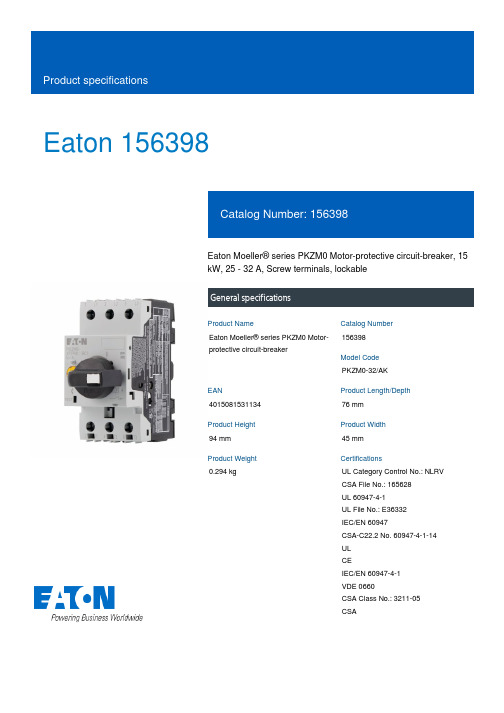
Eaton 156398Eaton Moeller® series PKZM0 Motor-protective circuit-breaker, 15 kW, 25 - 32 A, Screw terminals, lockableGeneral specificationsEaton Moeller® series PKZM0 Motor-protective circuit-breaker156398PKZM0-32/AK401508153113476 mm 94 mm 45 mm 0.294 kgUL Category Control No.: NLRV CSA File No.: 165628 UL 60947-4-1 UL File No.: E36332 IEC/EN 60947CSA-C22.2 No. 60947-4-1-14 UL CEIEC/EN 60947-4-1 VDE 0660CSA Class No.: 3211-05 CSAProduct NameCatalog Number Model Code EANProduct Length/Depth Product Height Product Width Product Weight CertificationsTurn buttonPhase-failure sensitivity (according to IEC/EN 60947-4-1, VDE 0660 Part 102)Motor protectionPhase failure sensitiveThree-pole 100,000 operations (at 400V, AC-3)100,000 Operations (Main conducting paths)Can be snapped on to IEC/EN 60715 top-hat rail with 7.5 or15 mm height.40 Operations/hIII3Motor protective circuit breakerFinger and back-of-hand proof, Protection against direct contact when actuated from front (EN 50274)6000 V AC25 g, Mechanical, according to IEC/EN 60068-2-27, Half-sinusoidal shock 10 msAlso motors with efficiency class IE3Branch circuit: Suitable for group installations, (UL/CSA)-25 - 55 °C, Operating range-5 - 40 °C to IEC/EN 60947, VDE 0660≤ 0.25 %/K, residual error for T > 40°Max. 2000 m -25 °C 2 x (1 - 6) mm², ferrule to DIN 46228 1 x (1 - 6) mm², ferrule to DIN 46228Actuator type Features Functions Number of poles Lifespan, electricalLifespan, mechanicalMounting positionOperating frequencyOvervoltage categoryPollution degreeProduct categoryProtectionRated impulse withstand voltage (Uimp) Shock resistanceSuitable forTemperature compensationAltitudeAmbient operating temperature - minTerminal capacity (flexible with ferrule)Terminal capacity (solid)55 °C25 °C40 °C40 °C80 °CDamp heat, cyclic, to IEC 60068-2-30 Damp heat, constant, to IEC 60068-2-782 x (1 - 6) mm²1 x (1 - 6) mm²18 - 1010 mm1 Nm, Screw terminals, Control circuit cables 1.7 Nm, Screw terminals, Main cable50 Hz60 Hz32 A7.5 kW15 kW690 V690 V32 A40 kA DC, up to 250 V DC, Main conducting paths150 A, 600 V High Fault, max. Fuse, SCCR (UL/CSA) 10 kA, 600 V High Fault, CB, SCCR (UL/CSA)10 kA, 600 V High Fault, Fuse, SCCR (UL/CSA)18 kA, 600 V High Fault, Fuse with CL, SCCR (UL/CSA) 18 kA, 600 V High Fault, CB with CL, SCCR (UL/CSA) 7.5 HP 5 HP 10 HPAmbient operating temperature - maxAmbient operating temperature (enclosed) - min Ambient operating temperature (enclosed) - max Ambient storage temperature - minAmbient storage temperature - maxClimatic proofing Terminal capacity (solid/stranded AWG)Stripping length (main cable)Tightening torqueRated frequency - minRated frequency - maxRated operational current (Ie)Rated operational power at AC-3, 220/230 V, 50 Hz Rated operational power at AC-3, 380/400 V, 50 Hz Rated operational voltage (Ue) - minRated operational voltage (Ue) - maxRated uninterrupted current (Iu)Short-circuit currentShort-circuit current rating (group protection)Assigned motor power at 200/208 V, 60 Hz, 3-phase Assigned motor power at 230/240 V, 60 Hz, 1-phase Assigned motor power at 230/240 V, 60 Hz, 3-phase Assigned motor power at 460/480 V, 60 Hz, 3-phase125 A, 600 V High Fault, max. CB, SCCR (UL/CSA)600 A, 600 V High Fault, max. CB with CL, SCCR (UL/CSA) 600 A, 600 V High Fault, max. Fuse with CL, SCCR (UL/CSA)± 20% tolerance, Trip blocksBasic device fixed 15.5 x Iu, Trip Blocks496 A, Irm, Setting range max.20 HP25 HPScrew terminals25 A32 AOverload trigger: tripping class 10 A 9.56 W0 W3.19 W32 A0 WMeets the product standard's requirements.Meets the product standard's requirements.Meets the product standard's requirements.Meets the product standard's requirements.Meets the product standard's requirements.Does not apply, since the entire switchgear needs to be evaluated.Does not apply, since the entire switchgear needs to be evaluated.Short-circuit releaseAssigned motor power at 575/600 V, 60 Hz, 3-phaseConnectionOverload release current setting - min Overload release current setting - max Tripping characteristic Equipment heat dissipation, current-dependent PvidHeat dissipation capacity PdissHeat dissipation per pole, current-dependent PvidRated operational current for specified heat dissipation (In) Static heat dissipation, non-current-dependent Pvs10.2.2 Corrosion resistance10.2.3.1 Verification of thermal stability of enclosures10.2.3.2 Verification of resistance of insulating materials to normal heat10.2.3.3 Resist. of insul. mat. to abnormal heat/fire by internal elect. effects10.2.4 Resistance to ultra-violet (UV) radiation10.2.5 Lifting10.2.6 Mechanical impactMeets the product standard's requirements.Does not apply, since the entire switchgear needs to be evaluated.Meets the product standard's requirements.Does not apply, since the entire switchgear needs to be evaluated.Does not apply, since the entire switchgear needs to be evaluated.Is the panel builder's responsibility.Is the panel builder's responsibility.Is the panel builder's responsibility.Is the panel builder's responsibility.Is the panel builder's responsibility.The panel builder is responsible for the temperature rise calculation. Eaton will provide heat dissipation data for the devices.Is the panel builder's responsibility. The specifications for the switchgear must be observed.Is the panel builder's responsibility. The specifications for the switchgear must be observed.The device meets the requirements, provided the information in the instruction leaflet (IL) is observed.Save time and space thanks to the new link module PKZM0-XDM32ME Motor Starters in System xStart - brochureSwitching and protecting motors - catalogProduct Range Catalog Switching and protecting motorseaton-manual-motor-starters-characteristic-characteristic-curve-008.eps eaton-manual-motor-starters-characteristic-characteristic-curve-009.eps eaton-manual-motor-starters-tripping-characteristic-pkzm0-characteristic-curve.epsDA-DC-00004892.pdfDA-DC-00004921.pdfeaton-manual-motor-starters-pkz-dimensions.epseaton-manual-motor-starters-pkz-dimensions-002.epseaton-manual-motor-starters-pkzm0-3d-drawing.epseaton-general-ie-ready-dilm-contactor-standards.epseaton-manual-motor-starters-pkzm0-3d-drawing-008.epseaton-manual-motor-starters-mounting-3d-drawing-002.epsDA-CE-ETN.PKZM0-32_AKIL03407010ZIL03402034ZWIN-WIN with push-in technologyIL122023ZUDA-CS-pkzm0_ak_neu_aDA-CD-pkzm0_ak_neu_aeaton-manual-motor-starters-transformer-pkzm0-wiring-diagram.eps10.2.7 Inscriptions10.3 Degree of protection of assemblies10.4 Clearances and creepage distances10.5 Protection against electric shock10.6 Incorporation of switching devices and components 10.7 Internal electrical circuits and connections10.8 Connections for external conductors10.9.2 Power-frequency electric strength10.9.3 Impulse withstand voltage10.9.4 Testing of enclosures made of insulating material 10.10 Temperature rise10.11 Short-circuit rating10.12 Electromagnetic compatibility10.13 Mechanical function BrochuresCatalogues Characteristic curve Declarations of conformity DrawingseCAD modelInstallation instructions Installation videos Manuals and user guides mCAD modelWiring diagramsEaton Corporation plc Eaton House30 Pembroke Road Dublin 4, Ireland © 2023 Eaton. All rights reserved. Eaton is a registered trademark.All other trademarks areproperty of their respectiveowners./socialmedia。
Huckepack HO 0433 F 旋转杠式胶囊吸力机说明书
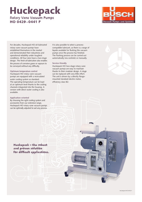
Technical data is subject to change. Created in Germany 06/NHuckepack HO 0429 - 0441 FArgentina Australia Austria Belgium Brazil Canada Chile China Czech Republic Denmark Finland France Germany Hungary India Ireland Israel Italy Japan Korea Malaysia Mexico New Zealand Netherlands Norway Poland Portugal Russia Singapore South Africa Spain Sweden Switzerland Taiwan Thailand Turkey United Arab Emirates United Kingdom USABusch Vacuum FZEA-3/71, Sharjah Airport International Free zone (SAIF- Zone) | P .B.No:121855,Sharjah|Phone+971065529174|************************|www.busch.aeTechnical specificationsThe Huckepack two-stage rotary vane vacuum pumps are specifically designed for particularly complex processes in the chemical and pharmaceutical industry. They are almost perfectly resistant to aggressive substances thanks to their perfectly coordinated materials. The carbon fibre composite vanes developed specially for this purpose have emergency running properties which guarantee operational safety and a high vacuum performance even with insufficientlubrication. For use in potentially explosive environments, Huckepack rotary vane vacuum pumps are also available in an ATEX version with an EC type-examination certificate in accordance with Directive 94/9/EC: ExII 2G IIB T3/T4 (i/o)Accessories/technical options • Lubricant separator • Various inlet filters• Flushing device, manual and automatic • Exhaust silencer• Monitoring and safety devices • ControlsPumping speed Air at 20 °C. Tolerance: ± 10%50 Hz 60 Hz。
- 1、下载文档前请自行甄别文档内容的完整性,平台不提供额外的编辑、内容补充、找答案等附加服务。
- 2、"仅部分预览"的文档,不可在线预览部分如存在完整性等问题,可反馈申请退款(可完整预览的文档不适用该条件!)。
- 3、如文档侵犯您的权益,请联系客服反馈,我们会尽快为您处理(人工客服工作时间:9:00-18:30)。
(V)(Ω)6.31610252247100220330470100015003300680022331502203304706801000220047006800102247681001502203304706801500330047001022B BC CD D D8EF F GH 13J16B B C D D8E F F F GH13J16K16B B C C D D D D8D8E F F GH13J16K16B C90901601602402402803006006008501100180090901602402803006006006008501100180020609090160160240240240280280300600600850110018002060901601.351.350.700.700.360.360.340.260.160.160.080.060.0351.351.350.700.360.340.260.160.160.160.080.060.0350.0331.351.350.700.700.360.360.360.340.340.260.160.160.080.060.0350.0331.350.7EEVFK0J220R EEVFK0J470UR EEVFK0J470R EEVFK0J101UR EEVFK0J101P EEVFK0J221P EEVFK0J331XP EEVFK0J331P EEVFK0J471P EEVFK0J102P EEVFK0J152PEEVFK1A220R EEVFK1A330UR EEVFK1A330R EEVFK1A151P EEVFK1A221XP EEVFK1A221P EEVFK1A331P EEVFK1A471P EEVFK1A681P EEVFK1A102PEEVFK1C100R EEVFK1C220UR EEVFK1C220R EEVFK1C470UR EEVFK1C470P EEVFK1C680P EEVFK1C101P EEVFK1C151XP EEVFK1C221XP EEVFK1C221P EEVFK1C331P EEVFK1C471P EEVFK1C681PEEVFK1E100R EEVFK1E220R20002000100010001000100090010005005005002001252000200010001000900100050050050050020012512520002000100010001000100010009009001000500500500200125125200010000.260.260.260.260.260.260.260.260.260.260.260.300.360.190.190.190.190.190.190.190.190.190.190.210.250.290.160.160.160.160.160.160.160.160.160.160.160.160.160.160.200.220.140.14Standard Productsn (µF)(m m )(m m )(m A )Part No.(RoHS:not compliant)SpecificationDia.Length TapingCase sizeCap.(±20%)W.V.Ripple current (100kHz)(+105°C)Min.Packaging Q'ty S i z e Code Impe-dance(100kHz)(+20°C)tan δ(120Hz)(+20°C)(pcs)44556.36.36.38881012.5164456.36.388881012.5161844556.36.36.36.36.38881012.51618455.85.85.85.85.85.87.76.210.210.210.213.516.55.85.85.85.87.76.210.210.210.210.213.516.516.55.85.85.85.85.85.85.87.77.76.210.210.210.213.516.516.55.85.8Endurance: 2000 to 5000h at 105°CPart No.(RoHS:compliant)EEEFK0J220R EEEFK0J470UR EEEFK0J470R EEEFK0J101UR EEEFK0J101P EEEFK0J221P EEEFK0J331XP EEEFK0J331P EEEFK0J471P EEEFK0J102P EEEFK0J152PEEVFK0J332Q EEVFK0J682MEEEFK1A220R EEEFK1A330UR EEEFK1A330R EEEFK1A151P EEEFK1A221XP EEEFK1A221P EEEFK1A331P EEEFK1A471P EEEFK1A681P EEEFK1A102PEEVFK1A222Q EEVFK1A472M EEVFK1A682MEEEFK1C100R EEEFK1C220UR EEEFK1C220R EEEFK1C470UR EEEFK1C470P EEEFK1C680P EEEFK1C101PEEEFK1C151XP EEEFK1C221XP EEEFK1C221P EEEFK1C331P EEEFK1C471P EEEFK1C681PEEVFK1C152Q EEVFK1C332M EEVFK1C472MEEEFK1E100R EEEFK1E220RReflowReflow(1)(1)(1)(1)(1)(1)(1)(2)(2)(2)(2)(1)(1)(1)(1)(1)(2)(2)(2)(2)(2)(1)(1)(1)(1)(1)(1)(1)(1)(1)(2)(2)(2)(2)(1)(1)(4)(4)(4)(4)(4)(4)(4)(5)(5)(5)(5)(2)(2)(4)(4)(4)(4)(4)(5)(5)(5)(5)(5)(2)(2)(2)(4)(4)(4)(4)(4)(4)(4)(4)(4)(5)(5)(5)(5)(2)(2)(2)(4)(4)The taping dimension are explained on p.187 of our Catalog. Please use it as a reference guide.Reflow Profile(Fig-1 to Fig-5) listed in a last page.Endurance: 2000 to 5000h at 105°CStandard Productsn(µF)(m m )(m m )(m A )Part No.(RoHS:not compliant)SpecificationDia.LengthTapingCase sizeCap.(±20%)W.V.Ripple current (100kHz)(+105°C)Min.Packaging Q'ty S i z e Code Impe-dance(100kHz)(+20°C)tan δ(120Hz)(+20°C)(pcs)(Ω)503347681001502203304701000220033004.71022334768100150220330470680100015004.710223347100150220330390470680100056.36.36.36.388881012.5161844556.36.36.36.38881012.512.51616456.36.36.386.388101012.512.51616165.85.85.85.87.76.210.210.210.210.213.516.516.55.85.85.85.85.85.87.77.710.210.210.210.213.513.516.516.55.85.85.85.87.76.27.76.210.210.210.213.513.516.516.516.5C D D D D8E F F F G H13J16K16B B C C D D D8D8F F F G H13H13J16J16B C D D D8E D8E F G G H13H13J16J16J161602402402402803006006006008501100180020609090160160240240280280600600600850110011001800180060851651651951951951953506706709009001610161016100.70.360.360.360.340.260.160.160.160.080.060.0350.0331.351.350.700.700.360.360.340.340.160.160.160.080.060.060.0350.0352.91.520.880.880.680.680.680.680.340.180.180.120.120.0730.0730.073EEVFK1E330UR EEVFK1E330P EEVFK1E470P EEVFK1E680P EEVFK1E101XP EEVFK1E101P EEVFK1E151P EEVFK1E221P EEVFK1E331P EEVFK1E471PEEVFK1V4R7R EEVFK1V100UR EEVFK1V100R EEVFK1V220R EEVFK1V330P EEVFK1V470P EEVFK1V680XP EEVFK1V101XP EEVFK1V101P EEVFK1V151P EEVFK1V221P EEVFK1V331PEEVFK1H4R7R EEVFK1H100UR EEVFK1H100P EEVFK1H220P EEVFK1H330XP EEVFK1H330P EEVFK1H470XP EEVFK1H470P EEVFK1H101P EEVFK1H151P EEVFK1H221P100010001000100090010005005005005002001251252000200010001000100010009009005005005005002002001251252000100010001000900100090010005005005002002001251251250.140.140.140.140.140.140.140.140.140.140.140.160.180.120.120.120.120.120.120.120.120.120.120.120.120.120.120.120.120.100.100.100.100.100.100.100.100.100.100.100.100.100.100.100.102535EEEFK1E330UR EEEFK1E330P EEEFK1E470P EEEFK1E680P EEEFK1E101XP EEEFK1E101P EEEFK1E151P EEEFK1E221P EEEFK1E331P EEEFK1E471P EEVFK1E102Q EEVFK1E222M EEVFK1E332M EEEFK1V4R7R EEEFK1V100UR EEEFK1V100R EEEFK1V220R EEEFK1V330P EEEFK1V470PEEEFK1V680XP EEEFK1V101XP EEEFK1V101P EEEFK1V151P EEEFK1V221P EEEFK1V331P EEVFK1V471Q EEVFK1V681Q EEVFK1V102M EEVFK1V152MEEEFK1H4R7R EEEFK1H100UR EEEFK1H100P EEEFK1H220P EEEFK1H330XP EEEFK1H330P EEEFK1H470XP EEEFK1H470P EEEFK1H101PEEEFK1H151P EEEFK1H221PEEVFK1H331Q EEVFK1H391Q EEVFK1H471M EEVFK1H681M EEVFK1H102MPart No.(RoHS:compliant)ReflowReflow(1)(1)(1)(1)(1)(2)(2)(2)(2)(2)(2)(2)(2)(1)(1)(1)(1)(1)(1)(1)(1)(2)(2)(2)(2)(1)(1)(1)(1)(1)(2)(1)(2)(2)(2)(2)(4)(4)(4)(4)(4)(5)(5)(5)(5)(5)(2)(2)(2)(4)(4)(4)(4)(4)(4)(4)(4)(5)(5)(5)(5)(2)(2)(2)(2)(4)(4)(4)(4)(4)(5)(4)(5)(5)(5)(5)(2)(2)(2)(2)(2)The taping dimension are explained on p.187 of our Catalog. Please use it as a reference guide.Reflow Profile(Fig-1 to Fig-5) listed in a last page.Standard Productsn (µF)(m m )(m m )(m A )Part No.(RoHS:compliant)SpecificationDia.LengthTapingCase sizeCap.(±20%)W.V.Ripplecurrent (100kHz)(+105°C)Min.Packaging Q'ty S i z e Code Impe-dance (100kHz)(+20°C)tan δ(120Hz)(+20°C)(pcs)(V)(Ω)4.710223347681001502204706803.34.71022334768100150330470223347681001502203305 6.3 6.3 8 8 8 81012.512.51618 5 6.3 6.3 8 8 81012.512.512.516188.01012.512.5161618185.85.87.76.210.210.210.210.213.513.516.516.55.85.87.76.210.210.210.213.513.513.516.516.510.210.213.513.516.516.516.516.5C D D8E F F F G H13H13J16K16C D D8E F F G H13H13H13J16K16F G H13H13J16J16K16K16508012012025025025040080080014101690254060601301302005005005007939171302005005007937939179173.01.51.21.20.650.650.650.350.160.160.0820.085.03.02.42.41.31.30.70.320.320.320.170.1531.30.70.320.320.170.170.1530.153EEVFK1J4R7R EEVFK1J100P EEVFK1J220XP EEVFK1J220P EEVFK1J330P EEVFK1J470P EEVFK1J680UP EEVFK1J101PEEVFK1K3R3R EEVFK1K4R7P EEVFK1K100XP EEVFK1K100P EEVFK1K220P EEVFK1K330P EEVFK1K470PEEVFK2A220P EEVFK2A330P1000100090010005005005005002002001251251000100090010005005005002002002001251255005002002001251251251250.080.080.080.080.080.080.080.080.080.080.080.080.080.080.080.080.080.080.080.080.080.080.080.080.070.070.070.070.070.070.070.0780100Endurance: 2000 to 5000h at 105°C63Part No.(RoHS:not compliant)EEEFK1J4R7R EEEFK1J100P EEEFK1J220XP EEEFK1J220P EEEFK1J330P EEEFK1J470P EEEFK1J680UP EEEFK1J101P EEVFK1J151Q EEVFK1J221Q EEVFK1J471M EEVFK1J681MEEEFK1K3R3R EEEFK1K4R7P EEEFK1K100XP EEEFK1K100P EEEFK1K220P EEEFK1K330P EEEFK1K470P EEVFK1K680Q EEVFK1K101Q EEVFK1K151Q EEVFK1K331M EEVFK1K471MEEEFK2A220P EEEFK2A330P EEVFK2A470Q EEVFK2A680Q EEVFK2A101M EEVFK2A151M EEVFK2A221M EEVFK2A331MReflowReflow(1)(1)(1)(2)(2)(2)(2)(2)(1)(1)(1)(2)(2)(2)(2)(2)(2)(4)(4)(4)(5)(5)(5)(5)(5)(2)(2)(2)(2)(4)(4)(4)(5)(5)(5)(5)(2)(2)(2)(2)(2)(5)(5)(2)(2)(2)(2)(2)(2)The taping dimension are explained on p.187 of our Catalog. Please use it as a reference guide.Reflow Profile(Fig-1 to Fig-5) listed in a last page.Part Number Prefix Suffix Size RoHS Terminal Finish MaterialsECEV• • • R R3φ to 5φNo Sn-Pb Peak Temp.: 240deg.C(within 5s),within 20s(time in200deg.C or more)Fig.1 6φ • • • Peak Temp.: 240deg.C(within5s),within 20s(time in 200deg.C or more)Fig.1 8 and 10φ •••Peak Temp.: 230deg.C(within5s),within 20s(time in 200deg.C or more)Fig.2EEV• • • R R4φ and 5φNo Sn-Pb Peak Temp.: 240deg.C(within 5s),within 20s(time in200deg.C or more)Fig.1 6φ • • • Peak Temp.: 240deg.C(within5s),within 20s(time in 200deg.C or more)Fig.1 8 and 10φ •••Peak Temp.: 230deg.C(within5s),within 20s(time in 200deg.C or more)Fig.2EEV• • • Q Q 12.5φOK Sn Fig.2 (Except for EB series)EEV• • • M M16φ and 18φOK Sn Fig.3 (EB series only)EEE • • R R3φ to 5φOK Sn-Bi Peak Temp.: 250deg.C(within 5s),within 60s(time in200deg.C or more)Fig. 4 6φ • • • Peak Temp.: 250deg.C(within5s),within 60s(time in 200deg.C or more)Fig. 4 8 and 10φ •••Peak Temp.: 235deg.C(within5s),within 60s(time in 200deg.C or more)Fig. 5(5)Peak Temp.: 230deg.C(within 5s),within 20s(time in200deg.C or more)Reflow ConditionP6φ to 10φOK Sn-BiSn-PbP6φ to 10φNoEEE• • • PEEESn-PbPEEV• • • P6φ to 10φNoEEVECEV• • • PECEV。
