【推荐下载】美国环境挥发性有机物的检测技术
美国挥发性有机物(VOC)
美国挥发性有机物(VOC)监测及减排最佳管理技术 :炼油厂案例分析致:能源基金会(中国)RTI International(三角国际研究院)美国北卡罗来纳州研究三角园科恩沃利斯东路3040号,邮政编码27709目录目录 (i)图表目录 (iv)缩略词列表 (v)I. 挥发性有机物与炼油厂概述 (1)II. 工艺排气 (2)A. 排放源描述 (2)B. 原标准的VOC污染防治要求 (2)C. 新增监测和污染防治技术要求 (2)III. 火炬 (3)A. 排放源描述 (3)B. 原标准的VOC污染防治要求 (3)C. 新增监测和污染防治技术要求 (3)1. 火炬管理计划 (4)2. 火炬绩效运行限值 (4)a. 引燃火焰的存在 (5)b. 可见排放 (5)c. 火炬头速度 (5)d. 燃烧区域净热值 (6)e. 周边空气助燃火炬的稀释限值 (6)3. 火炬紧急情况的管理规定 (7)IV. 设备泄漏 (7)A. 排放源描述 (7)B. 原标准的VOC污染防治要求 (7)C. 新增监测和污染防治技术要求 (8)1. 监测 (8)a. 泄漏的定义 (8)b. 泄漏探测方法 (8)c. 记录保存要求 (9)2. 污染防治新技术 (9)a. 阀门和阀门盘根 (10)c. 泵 (11)V. 储罐 (11)A. 排放源描述 (11)B. 原标准的VOC污染防治要求 (11)1. 内浮顶储罐 (11)2. 外浮顶储罐 (11)3. 外浮顶储罐改造为内浮顶储罐 (12)4. 一般储罐的要求 (12)C. 新增监测和污染防治技术要求 (12)VI. 废水系统 (13)A. 排放源描述 (13)1. 废水收集系统 (13)2. 废水处理系统 (13)B. 原标准的VOC污染防治要求 (14)1. 废水收集系统 (14)2. 废水处理系统 (15)C. 新增监测和污染防治技术要求 (16)VII. 热交换系统 (16)A. 排放源描述 (16)1. 闭路再循环热交换系统 (17)2. 一次性交换系统 (17)B. 原标准的VOC污染防治要求 (17)C. 新增监测和污染防治技术要求 (18)VIII. 总体改善 (19)A. 边界监测要求 (19)1. 被动监测仪的描述 (20)2. 监测仪的布局 (20)4. 背景校正 (21)5. 实践要求 (22)B. 其它泄漏探测新方法 (22)2. 主动采样器 (23)3. 开放式监测仪 (23)a. UV-DOAS (23)b. 傅立叶变换红外线(FTIR) (23)c. 差异吸收光探测和测距(DIAL) (23)d. 红外掩日通量 (24)C. 紧急泄漏情况的管理规定 (24)IX. 参考资料与文献 (26)图表目录图表 1. 地表臭氧的形成 (1)图表 2. 火炬产生的可见排放 (4)图表 3. 火炬烟道及不同水平的可见排放 (5)图表 4. 炼油厂各类设备的数量及其产生的无组织排放 (8)图表 5. FLIR相机 (9)图表 6. 未安装和已安装污染防治技术的有槽导柱的比较 (12)图表 7. 废水无组织排放源示例 (13)图表 8. 废水收集系统 (15)图表 9. 热交换系统 (16)图表 10. 热交换系统 (17)图表 11. 汽提装置 (18)图表 12. 边界监测使用的被动扩散管采样器 (20)图表 13. 美国某炼油厂的边界监测布局 (21)图表 14. 泄压装置的排放 (24)缩略词列表APCD Air Pollution Control Device,大气污染防治设备Btu British Thermal Units,英热单位cm Centimeters,厘米DIAL Differential Absorption Light Detection and Ranging,差异吸收光探测和测距EPA Environmental Protection Agency,美国联邦环保署Fbio Fraction biodegraded,部分生物降解GPS Global Positioning System,全球定位系统FTIR Fourier Transform Infrared,傅立叶变换红外线HAP Hazardous Air Pollutant,有害大气污染物kg kilogram,千克kPa kilopascal,千帕lbs pound,磅m meter,米m3cubic meter,立方米µg/m3microgram per cubic meter,微克每立方米NHV Net Heating Value,净热值ppb parts per billion,十亿分率ppm parts per million,百万分率ppmv parts per million by volume,体积的百万分率ppmw parts per million by weight,重量的百万分率PRD Pressure Relief Device,泄压装置psig pounds per square inch,磅每平方英寸PTFE Polytetrafluoroethylene,聚四氟乙烯scf standard cubic feet,标准立方英尺US United States,美国UV-DOAS Ultra Violet Differential Optical Adsorption Spectrometer,紫外线差异光学吸附光谱仪V max Maximum flare tip velocity,最大火炬头速度VOC V olatile Organic Compounds,挥发性有机物I. 挥发性有机物与炼油厂概述炼油厂和石化厂是美国乃至全世界范围内最大的挥发性有机物(VOC)排放源。
美国地下水和饮用水井中挥发性有机物分析
美国地下水和饮用水井中挥发性有机物分析美国内政部美国地质调查局李烨译;冯翠娥、田芳校译挥发性有机物(VOCs)正在被大量生产,与之相关的产品有塑料、粘合剂、涂料、汽油、薰剂、制冷剂和干洗剂等。
VOCs被广泛使用,而且这种物质能够在地下水中迁移并持久存在,因此对环境造成了许多负面影响,如对饮用水水质的影响。
USGS国家水质评价(NAWQA)计划根据1985~2002年的取样结果,所进行的长期研究对地下水中的VOCs进行了一次全面的全国性分析。
研究结果表明,在全国大部分的含水层中都能检测到VOCs,然而,在近3500个取样井中,许多井并没有检测到VOCs,例如80%的水井中的VOCs没有超过检出限0.2ppb。
最常检出的VOCs是氯仿、四氯乙烯(PCE)、三氯乙烯(TCE)和汽油添加剂甲基叔丁基醚(MTBE);评价工作中选择的55种VOCs,有13种完全没有检测出。
对作为饮用水的未经处理的地下水样进行分析,结果表明在生活供水井(14%)和公共水井(26%)的水样中检测到了VOCs,但是浓度都不足以对人体健康产生有害影响(不到2%水样的浓度高于联邦饮用水标准)。
本事实清单对全国和区域地下水和饮用水井中的VOCs的分布进行了汇总,是USGS通告(1292)“全国水质-地下水和饮用水井中的挥发性有机物”的辅助成果。
一、研究地下水中VOCs的重要性保护和管理地下水是一项重要的工作。
在美国,约有一半人口以地下水作为饮用和其它生活用水水源,而且地下水也是维持工农业生产和商业活动的重要自然资源。
VOCs是一类重要的环境污染物,由于其广泛和长期的使用,因而需要监测和管理地下水中的这类物质。
许多VOCs可以在地下水中运移和滞留,其中一些已经确定或怀疑对人类有致癌作用,美国环保局(USEPA)对公共水系统中的VOCs浓度进行了控制。
VOCs可以释放到环境中,通过不同的污染源和途径到达地下水,包括汽油发动机排气、工业废气、储油罐泄漏、垃圾填埋、城市废水入渗、化粪池和水井的注入等。
环境检测中挥发性有机物检测方法的合理运用

环境检测中挥发性有机物检测方法的合理运用摘要:在我国,挥发性有机物指常温下饱和蒸气压大于70Pa,常压下沸点在260℃以下的有机化合物,或在20℃条件下,蒸气压大于或等于10Pa且具有挥发性的全部有机化合物。
挥发性有机物常被分成以下几大类:含氮有机化合物、含氧有机化合物、含硫有机化合物、非甲烷碳氢化合物等。
挥发性有机物对自然环境有污染性,研究表明,挥发性有机物参与大气环境中臭氧和二次溶胶的形成,对区域性的大气环境有很大影响。
目前,挥发性有机物监测是环境监测中的一项重要内容。
下面对挥发性有机物检测技术及检测注意事项等做具体分析。
关键词:环境检测;挥发性;有机物检测;合理运用1挥发性有机物的危害挥发性有机物,简称为(VOCs),是在常温条件下沸点处于50~260℃不等的多种有机化合物,包括含硫有机化合物、含氮有机化合物、非甲烷碳氢化合物等类型,绝大多数有机化合物都具备较强的毒性、污染性和刺激性,并具有令人不适的特殊气味。
目前来看,挥发性有机物所造成危害影响主要体现在损害人体健康、污染生态环境两方面。
第一,在损害人体健康方面,如果大气环境中的VOCs浓度超过安全标准,在VOCs与人体接触后会对皮肤和裸露在外的器官造成刺激作用,在吸入人体后对呼吸道系统与中枢神经系统造成严重伤害或是不可逆转的永久性伤害,由此出现呼吸困难、神经系统障碍、血液缺氧、癌症等症状与健康问题。
第二,在污染生态环境方面,在空气中VOCs浓度超标情况下,VOCs 与臭氧进行反应,随着时间推移,持续降低大气臭氧浓度,最终造成加剧温室效应、破坏臭氧层、引发全球性气候灾害等严重后果。
2环境检测中挥发性有机物检测方法的合理运用2.1合理选择与应用检测技术在挥发性有机物检测工作时,要根据检测地点、检测环境、检测质量要求等设计可行的技术方案,选择先进合适的检测技术,以提高检测质量。
此外,还要选择合适的检测仪器。
应用气相色谱法检测挥发性有机物时,仪器是关键,仪器的精度、灵敏度等直接影响检测结果。
(环境管理)环境空气挥发性有机物的测定-T吸附GCMS法
(环境管理)环境空⽓挥发性有机物的测定-T吸附GCMS 法美国EPA TO-17 ⽅法分析环境空⽓中挥发性有机物研究施巍蔡浩洋(⼤连市环境监测中⼼⼤连 116023)摘要选⽤美国EPA TO-17⽅法中的⼀种类型的混合型填料吸附管,分析环境空⽓中挥发性有机物。
通过实验验证EPA TO-17⽅法的可⾏性和可操作性,并得到校正曲线、相关系数、检出限等数据。
关键词挥发性有机物吸附管吸附解析1 前⾔1.1 ⽅法概述本⽅法⽤于环境空⽓中挥发性有机化合物的采集和测定。
本次研究的挥发性有机化合物是指能由35mm Carbopack?B和10mm Carbosieve?SⅢ及Carboxen?1000组成的吸附管捕集,并能⽤热脱附GC/MS技术测定的挥发性有机化合物。
1.2 国内外概况随着⼯业的快速发展,有机物的污染逐步显现。
⽬前,许多国家都根据本国⼤⽓环境污染状况制定相应的防治法或环境标准。
对环境空⽓中的挥发性有机物测定,美国EPA TO-1⽅法采⽤的是Tenax采样GC-MS法,其分析的化合物为沸点⼤约在80℃-200℃的⾮极性有机化合物。
TO-2是采⽤碳分⼦筛采样GC-MS法,主要采集含碳数少的、挥发性强的有机物。
TO-14和TO-15采⽤的是采样罐采样GC-MS法,其与TO-1⽅法区别是进样⽅式不⼀样,能检测化合物⽐TO-1多,但因为其进样设备昂贵,现阶段很难在我国推⼴。
TO-17⽅法采⽤的是固体填料吸附管采样GC-MS法,不同的填料类型可测定不同的挥发性有机物,采集和测定的化合物种类较多。
我国《空⽓和废⽓监测分析⽅法》(第四版)采⽤了固体吸附GC-MS法和采样罐采样GC-MS法,这两种⽅法都是C类⽅法⽽且没有给出检出限和准确度等数据。
国标GB11737-89和GB14677-93也是采⽤固体吸附,⼆硫化碳洗脱或热解析的⽅法,但其能测定的⽬标化合物太少,只局限于苯系物。
综合分析,本论⽂在相关⽂献资料和EPA相关⽅法基础上,提出并建⽴⽤混合型填料吸附管吸附、GC-MS法测定环境空⽓中的挥发性有机物的⽅法。
环境空气 挥发性有机物的测定 美国EPA Method TO-3
METHOD TO-3 REVISION 1.0April, 1984 METHOD FOR THE DETERMINATION OF VOLATILE ORGANIC COMPOUNDSIN AMBIENT AIR USING CRYOGENIC PRECONCENTRATION TECHNIQUES AND GAS CHROMATOGRAPHY WITH FLAME IONIZATION ANDELECTRON CAPTURE DETECTION1.Scope1.1This document describes a method for the determination ofhighly volatile compounds having boiling points in therange of -10 to 200E C.1.2The methodology detailed in this document is currentlyemployed by numerous laboratories (1-4;8-11).Modifications to this methodology should be accompaniedby appropriate documentation of the validity andreliability of these changes.2.Applicable Documents2.1ASTM StandardsD1356 Definition of Terms Related to Atmospheric Samplingand AnalysisE 355 Recommended Practice for Gas Chromatography Termsand Relationships2.2Other DocumentsAmbient Air Studies (1-4).U. S. EPA Technical Assistance Document (5).3.Summary of Method3.1Ambient air analyses are performed as follows. Acollection trap, as illustrated in Figure 1, is submergedin either liquid oxygen or argon. Liquid argon is highlyrecommended for use because of the safety hazardassociated with liquid oxygen. With the sampling valvein the fill position an air sample is then admitted intothe trap by a volume measuring apparatus. In themeantime, the column oven is cooled to a sub-ambienttemperature (-50E C). Once sample collection iscompleted, the valve is switched so that the carrier gassweeps the contents of the trap onto the head of thecooled GC column. Simultaneously, the liquid cryogen isremoved and the trap is heated to assist the sampletransfer process. The GC column is temperatureprogrammed and the component peaks eluting from thecolumns are identified and quantified using flameionization and/or electron capture detection. Alternatedetectors (e.g., photoionization) can be used asappropriate. An automated system incorporating thesevarious operations as well as the data processingfunction has been described in the literature (8,9).3.2Due to the complexity of ambient air samples, highresolution (capillary column) GC techniques arerecommended. However, when highly selective detectors(such as the electron capture detector) are employed,packed column technology without cryogenic temperatureprogramming can be effectively utilized in some cases.4.Significance4.1Volatile organic compounds are emitted into theatmosphere from a variety of sources including industrialand commercial facilities, hazardous waste storagefacilities, etc. Many of these compounds are toxic,hence knowledge of the levels of such materials in theambient atmosphere is required in order to determinehuman health impacts.4.2Because these organic species are present at ppb levelsor below, some means of sample preconcentration isnecessary in order to acquire sufficient material foridentification and quantification. The two primarypreconcentration techniques are cryogenic collection andthe use of solid adsorbents. The method described hereininvolves the former technique.5.DefinitionsDefinitions used in this document and any user prepared SOPs should be consistent with ASTM D1356(6). All abbreviations and symbols are defined within this document at the point of use.6.Interferences/Limitations6.1Compounds having similar GC retention times willinterfere in the method. Replacing the flame ionizationdetector with more selective detection systems will helpto minimize these interferences. Chlorinated species, inparticular, should be determined using the electroncapture detector to avoid interference from volatilehydrocarbons.6.2An important limitation of the technique is thecondensation of moisture in the collection trap. Thepossibility of ice plugging the trap and stopping theflow is of concern, and water subsequently transferred tothe capillary column may also result in flow stoppage andcause deleterious effects to certain column materials.Use of permaselective Nafion® tubing in-line before thecryogenic trap avoids this problem; however, the materialmust be used with caution because of possible losses ofcertain compounds. Another potential problem iscontamination from the Nafion® tubing. The user shouldconsult the literature (7-12) for details on the use ofpermeation-type driers.7.Apparatus7.1Gas chromatograph/Flame Ionization/Electron CaptureDetection System - must be capable of subambienttemperature programming. A recent publication (8)describes an automated GC system in which the cryogenicsampling and analysis features are combined. This systemallows simultaneous flame ionization and electron capturedetection.7.2Six-port sampling valve - modified to accept a samplecollection trap (Figure 1).7.3Collection trap - 20 cm x 0.2 cm I.D. stainless steeltubing packed with 60/80 mesh silanized glass beads andsealed with glass wool. For the manual system (Section9.2) the trap is externally wrapped with 28 gauge (duplexand fiberglass insulated) type "K" thermocouple wire.This wire, beaded at one end, is connected to a powerstatduring the heating cycle. A thermocouple is alsoattached to the trap as shown in Figure 1.7.4Powerstat - for heating trap.7.5Temperature readout device - for measuring traptemperature during heating cycle.7.6Glass dewar flask - for holding cryogen.7.7Sample volume measuring apparatus - capable of accuratelyand precisely measuring a total sample volume up to 500cc at sampling rates between 10 and 200 cc/minute. SeeSection 9.7.8Stopwatch.7.9Dilution container for standards preparation - glassflasks or Teflon (Tedlar) bags, .002 inch film thickness(see Figure 2).7.10Liquid microliter syringes - 5-50 F l for injecting liquidstandards into dilution container.7.11Volumetric flasks - various sizes, 1-10 mL.7.12GC column - Hewlett Packard 50 meter methyl siliconecross-linked fused silica column (.3 mm I.D., thick film)or equivalent.7.13Mass flow controller - 10-200 mL/minute flow controlrange.7.14Permeation drier - PermaPure® - Model MD-125F, orequivalent. Alternate designs described in theliterature (7-12) may also be acceptable.8.Reagents and Materials8.1Glass beads - 60/80 mesh, silanized.8.2Glasswool - silanized.8.3Helium - zero grade compressed gas, 99.9999%.8.4Hydrogen - zero grade compressed gas, 99.9999%.8.5Air - zero grade compressed gas.8.6Liquid argon (or liquid oxygen).8.7Liquid nitrogen.8.8SRM 1805 - benzene in nitrogen standard. Available fromthe National Bureau of Standards. Additional suchstandards will become available in the future.8.9Chemical standards - neat compounds of interest, highestpurity available.9.Sampling and Analysis ApparatusTwo systems are described below which allow collection of an accurately known volume of air (100-1000 mL) onto a cryogenically cooled trap. The first system (Section 9.1) is an automated device described in the literature (8,9). The second system (Section 9.2) is a manual device, also described in the literature(2).9.1The automated sampling and analysis system is shown inFigure 3. This system is composed of an automated GC system (Hewlett Packard Model 5880A, Level 4, or equivalent) and a sample collection system (Nutech Model 320-01, or equivalent). The overall system is described in the literature (8).9.1.1The electronic console of the sampling unitcontrols the mechanical operation of the six-port valve and cryogenic trapping componentsas well as the temperatures in each of thethree zones (sample trap, transfer line, andvalve).9.1.2The valve (six-port air activated, SeiscorModel 8 or equivalent) and transfer line areconstantly maintained at 120E C. During samplecollection the trap temperature is maintainedat -160 + 5E C by a flow of liquid nitrogencontrolled by a solenoid valve. A cylindrical250 with heater, held in direct contact withthe trap, is used to heat the trap to 120E C in60 seconds or less during the sampledesorption step. The construction of thesample trap is described in Section 7.3.9.1.3The sample flow is controlled by a pump/massflow controller assembly, as shown in Figure3. A sample flow of 10-100 mL/minute isgenerally employed, depending on the desiredsampling period. A total volume of 100-1000mL is commonly collected.9.1.4In many situations a permaselective drier(e.g., Nafion®) may be required to removemoisture from the sample. Such a device isinstalled at the sample inlet. Twoconfigurations for such devices are available.The first configuration is the tube and shelltype in which the sample flow tube issurrounded by an outer shell through which acountercurrent flow of clean, dry air ismaintained. The dry air stream must be freefrom contaminants and its flow rate should be3-4 times greater than the sample flow toachieve effective drying. A secondconfiguration (7) involves placing a dryingagent, e.g., magnesium carbonate, on theoutside of the sample flow tube. Thisapproach eliminates the need for a source ofclean air in the field. However, contaminationfrom the drying agent can be a problem.V s ')P760×298TA%2739.2The manual sampling consists of the sample volumemeasuring apparatus shown in Figure 4 connected to the cryogenic trap/GC assembly shown in Figure 1. The operation of this assembly is described below.9.2.1Pump-Down PositionThe purpose of the pump-down mode of operationis to evacuate the ballast tank in preparationfor collecting a sample as illustrated inFigure 4. (While in this position, helium canalso be utilized to backflush the sample line,trap, etc. However, this cleaning procedureis not normally needed during most samplingoperations). The pump used for evacuating thesystem should be capable of attaining 200 torrpressure.9.2.2Volume Measuring PositionOnce the system has been sufficientlyevacuated, the 4-way ball valve is switched toprepare for sample collection. The 3-positionvalve is used to initiate sample flow whilethe needle valve controls the rate of flow.9.2.3Sample Volume CalculationThe volume of air that has passed through thecollection trap corresponds to a known changein pressure within the ballast tank (asmeasure by the Wallace Tiernan gauge).Knowing the volume, pressure change, andtemperature of the system, the ideal gas lawcan be used to calculate the number of molesof air sampled. On a volume basis, thisconverts to the following equation:whereV =Volume sampled at 760 mm Hg pressure ands25E C.)P =Change in pressure within the ballasttank, mm of Hg.V =Volume of ballast tank and gauge.T =Temperature of ballast tank, E C.AThe internal volume of the ballast tank and gauge can be determined either by H O displacement or by injecting2calibrated volumes of air into the system using large volume syringes, etc.10.Sampling and Analysis Procedure - Manual Device10.1This procedure assumes the use of the manual samplingsystem described in Section 9.2.10.2Prior to sample collection, the entire assembly should beleak-checked. This task is accomplished by sealing thesampling inlet line, pumping the unit down and placingthe unit in the flow measuring mode of operation. Aninitial reading on the absolute pressure gauge is takenand rechecked after 10 minutes. No apparent changeshould be detected.10.3Preparation for sample collection is carried out byswitching the 6-port valve to the "fill" position andconnecting the heated sample line to the sample source.Meanwhile the collection trap is heated to 150E C (orother appropriate temperature). The volume measuringapparatus is pumped-down and switched to the flowmeasuring mode. The 3-position valve is opened and aknown volume of sample is then passed through the heatedsample line and trap to purge the system.10.4After the system purge is completed, the 3-position valveis closed and the corresponding gauge pressure isrecorded. The collection trap is then immersed into adewar of liquid argon (or liquid oxygen) and the 3-position valve is temporarily opened to draw in a knownvolume of air, i.e. a change in pressure corresponds toa specific volume of air (see Section 9). Liquidnitrogen cannot be used as the cryogen since it will alsocondense oxygen from the air. Liquid oxygen representsa potential fire hazard and should not be employed unlessabsolutely necessary.10.5After sample collection is completed, the 6-port valve isswitched to the inject position, the dewar is removed andthe trap is heated to 150E C to transfer the samplecomponents to the head of the GC column which isinitially maintained at -50E C. Temperature programmingis initiated to elute the compounds of interest.10.6 A GC integrator (or data system if available) isactivated during the injection cycle to provide componentidentification and quantification.11.Sampling and Analysis Procedure - Automated Device11.1This procedure assumes the use of the automated systemshown in Figure 3. The components of this system arediscussed in Section 9.1.11.2Prior to initial sample collection the entire assemblyshould be leak-checked. This task is completed bysealing the sample inlet line and noting that the flowindication or the mass flow controller drops to zero(less than 1 mL/minute).11.3The sample trap, valve, and transfer line are heated to120E C and ambient air is drawn through the apparatus(-60mL/minute) for a period of time 5-10 minutes to flushthe system, with the sample valve in the inject position.During this time the GC column is maintained at 150E C tocondition the column.11.4The sample trap is then cooled to -160 + 5E C using acontrolled flow of liquid nitrogen. Once the traptemperature has stabilized, sample flow through the trapis initiated by placing the valve in the inject positionand the desired volume of air is collected.11.5During the sample collection period the GC column isstabilized at -50E C to allow for immediate injection ofthe sample after collection.11.6At the end of the collection period the valve isimmediately placed in the inject position, and thecryogenic trap is rapidly heated to 120E C to desorb thecomponents onto GC column. The GC temperature programand data acquisition are initiated at this time.11.7At the desired time the cryogenic trap is cooled to-160E C, the valve is returned to the collect position andthe next sample collection is initiated (to coincide withthe completion of the GC analysis of the previoussample).12.Calibration ProcedurePrior to sample analysis, and approximately every 4-6 hours thereafter, a calibration standard must be analyzed, using the identical procedure employed for ambient air samples (either Section 10 or 11). This section describes three alternative approaches for preparing suitable standards.12.1Teflon® (or Tedlar®) Bags12.1.1The bag (nominal size; 20L) is filled withzero air and leak checked. This can be easilyaccomplished by placing a moderate weight(text book) on the inflated bag and leavingovernight. No visible change in bag volumeindicates a good seal. The bag should also beequipped with a quick-connect fitting forsample withdrawal and an insertion port forliquid injections (Figure 2).12.1.2Before preparing a standard mixture, the bagis sequentially filled and evacuated with zeroair (5 times). After the 5th filling, asample blank is obtained using the samplingprocedure outlined in Section 10.12.1.3In order to prepare a standard mixture, thebag is filled with a known volume of zero air.This flow should be measured via a calibratedmass flow controller or equivalent flowmeasuring device. A measured aliquot of eachanalyte of interest is injected into the bagthrough the insertion port using a microlitersyringe. For those compounds with vaporpressures lower than benzene or for stronglyadsorbed species, the bag should be heated(60E C oven) during the entire calibrationperiod.12.1.4To withdraw a sample for analysis, thesampling line is directly connected to thebag. Quick connect fittings allow this hook-up to be easily accomplished and alsominimizes bag contamination from laboratoryair. Sample collection is initiated asdescribed.12.2Glass Flasks12.2.1If a glass flask is employed (Figure 2) theexact volume is determined by weighing theflask before and after filling with deionizedwater. The flask is dried by heating at200E C.12.2.2To prepare a standard, the dried flask isflushed with zero air until cleaned (i.e., ablank run is made). An appropriate aliquot ofeach analyte is injected using the sameprocedures as described for preparing bagstandards.12.2.3To withdraw a standard for analysis, the GCsampling line is directly connected to theflask and a sample obtained. However, becausethe flask is a rigid container, it will notremain at atmospheric pressure after samplinghas commenced. In order to prevent room airleakage into the flask, it is recommended thatno more than 10% of the initial volume beexhausted during the calibration period (i.e.,200cc if a 2 liter flask is used).12.3Pressurized Gas Cylinders12.3.1Pressurized gas cylinders containing selectedanalytes at ppb concentrations in air can beprepared or purchased. A limited number ofanalytes (e.g., benzene, propane) areavailable from NBS.12.3.2Specialty gas suppliers will prepare customgas mixtures, and will cross reference theanalyte concentrations to an NBS standard foran additional charge. In general, the usershould purchase such custom mixtures,ratherthan attempting to prepare them becauseof the special high pressure filling apparatusrequired. However, the concentrations shouldbe checked, either by the supplier or the userusing NBS reference materials.12.3.3Generally, aluminum cylinders are suitablesince most analytes of potential interest inthis method have been shown to be stable forat least several months in such cylinders.Regulators constructed of stainless steel andTeflon® (no silicon or neoprene rubber).12.3.4Before use the tank regulator should beflushed by alternately pressuring with thetank mixture, closing the tank valve, andventing the regulator contents to theatmosphere several times.12.3.5For calibration, a continuous flow of the gasmixture should be maintained through a glassor Teflon® manifold from which the calibrationstandard is drawn. To generate variouscalibration concentrations, the pressurizedgas mixture can be diluted, as desired, withzero grade air using a dynamic dilution system(e.g., CSI Model 1700).13.Calibration Strategy13.1Vapor phase standards can be prepared with either neatliquids or diluted liquid mixtures depending upon theconcentration levels desired. It is recommended thatbenzene also be included in this preparation scheme sothat flame ionization detector response factors, relativeto benzene, can be determined for the other compounds.The benzene concentration generated in this fashionshould be cross-checked with an NBS (e.g., SRM 1805) foraccuracy determinations.13.2Under normal conditions, weekly multipoint calibrationsshould be conducted. Each multipoint calibration shouldinclude a blank run and four concentration levels for thetarget species. The generated concentrations shouldbracket the expected concentration of ambient airsamples.13.3 A plot of nanograms injected versus area using a linearleast squares fit of the calibration data will yield thefollowing equation:Y'A%BXwhereY = quantity of component, nanogramsA = interceptB = slope (response factor)If substantial nonlinearity is present in the calibrationcurve a quadratic fit of the data can be used:Y'A%BX%CX2whereC = constantAlternatively, a stepwise multilevel calibration scheme may be used if more convenient for the data system in use.14.Performance Criteria and Quality AssuranceThis section summarizes the quality assurance (QA) measures and provides guidance concerning performance criteria which should be achieved within each laboratory.14.1Standard Operating Procedures (SOPs)14.1.1Each user should generate SOPs describing thefollowing activities as accomplished in theirlaboratories:1)assembly, calibration and operation ofthe sampling system.2)preparation and handling of calibrationstandards.3)assembly, calibration and operation ofthe GC/FID system and4)all aspects of data recording andprocessing.14.1.2SOPs should provide specific stepwiseinstructions and should be readily availableto, and understood by, the laboratorypersonnel conducting the work.14.2Method Sensitivity, Precision and Accuracy14.2.1System sensitivity (detection limit) for eachcomponent is calculated from the data obtainedfor calibration standards. The detectionlimit is defined asDL'A%3.3SwhereDL =calculated detection limit in nanogramsinjected.A =intercept calculated in Section 13.S =standard deviation of replicatedetermination of the lowest levelstandard (at least three determinationsare required).For many compounds detection limits of 1 to 5nanograms are found using the flame ionizationdetection. Lower detection limits can beobtained for chlorinated hydrocarbons usingthe electron capture detector.14.2.2 A precision of + 5% (relative standarddeviation) can be readily achieved atconcentrations 10 times the detection limit.Typical performance data are included in Table1.14.2.3Method accuracy is estimated to be within +10%, based on National Bureau of Standardcalibrated mixtures.REFERENCES1.Holdren, M., Spicer, C., Sticksel, P., Nepsund, K., Ward, G.,and Smith, R., "Implementation and Analysis of Hydrocarbon Grab Samples from Cleveland and Cincinnati 1981 Ozone Monitoring Study", EPA-905/4-82-001. U.S. Environmental Protection Agency, Research Triangle Park, North Carolina, 1982.2.Westberg, H., Rasmussen, R., and Holdren, M., "GasChromatographic Analysis of Ambient Air for Light Hydrocarbons Using a Chemically Bonded Stationary Phase", Anal. Chem. 46, 1852-1854, 1974.3.Lonneman, W. A., "Ozone and Hydrocarbon Measurements in RecentOxidant Transport Studies", in Int. Conf. on Photochemical Oxidant Pollutant and Its Control Proceedings, EPA-600/3-77-001a, 1977.4.Singh, H., "Guidance for the Collection and Use of AmbientHydrocarbon Species Data in Development of Ozone Control Strategies", EPA-450/4-80-008. U.S. Environmental Protection Agency, Research Triangle Park, North Carolina, 1980.5.Riggin, R. M., "Technical Assistance Document for Sampling andAnalysis of Toxic Organic Compounds in Ambient Air", EPA-600/4-83-027. U.S. Environmental Protection Agency, Research Triangle Park, North Carolina, 1983.6.Annual Book of ASTM Standards, Part 11.03, "AtmosphericAnalysis", American Society for Testing and Materials, Philadelphia, Pennsylvania, 1983.7.Foulger, B. E. and P. G. Sinamouds, "Drier for Field Use inthe Determination of Trace Atmospheric Gases", Anal. Chem., 51, 1089-1090, 1979.8.Pheil, J. D. and W. A. McClenney, "Reduced TemperaturePreconcentration Gas Chromatographic Analysis of Ambient Vapor-Phase Organic Compounds: System Automation", Anal.Chem., submitted, 1984.9.Holdren, M. W., W. A. McClenney, and R. N. Smith "ReducedTemperature Preconcentration and Gas Chromatographic Analysis of Ambient Vapor-Phase Organic Compounds: System Performance", Anal. Chem., submitted, 1984.10.Holdren, M., S. Rust, R. Smith, and J. Koetz, "Evaluation ofCryogenic Trapping as a Means for Collecting Organic Compounds in Ambient Air", Draft Final Report on Contract No. 68-02-3487, 1984.11.Cox, R. D. and R. E. Earp, "Determination of Trace LevelOrganics in Ambient Air by High-Resolution Gas Chromatography with Simultaneous Photoionization and Flame Ionization Detection", Anal. Chem. 54, 2265-2270, 1982.12.Burns, W. F., O. T. Tingy, R. C. Evans and E. H. Bates,"Problems with a Nafion® Membrane Dryer for Chromatographic Samples", J. Chrom. 269, 1-9, 1983.Figure 1. Schematic of Six-Port Valve Used for Sample Collection.Figure 2. Dilution Containers for Standard MixturesFigure 3. Automated Sampling and Analysis System for Cryogenic TrappingFigure 4. Sample Volume Measuring Apparatus。
环境监测中挥发性有机物监测方法的运用
环境监测中挥发性有机物监测方法的运用摘要:挥发性有机化合物(VOCs)通常伴随在空气中。
挥发性有机化合物实际上是空气中的化合物。
这些化合物的沸点在50℃到250℃之间。
在室温下,这些有害的VOC往往以整机的模式存在,甚至有几十种。
这些挥发物大多含有环芳烃,当空气中的挥发性有机化合物超过一定值时,会对人体造成伤害,增加致癌的可能性。
挥发性有机化合物的来源实际上由两类组成。
一种是自然因素,顾名思义,指的是动物、植物和微生物;其次是人为因素,主要是人们日常生活中汽车尾气的排放和工业生产中化工厂污染源的排放。
现在,我们生活环境中的空气中经常有PM2和O3污染,这是由挥发性有机化合物造成的。
关键词:环境监测;挥发性;有机物监测;方法运用1.挥发性有机化合物的定义挥发性有机化合物(VOCs)(以下简称VOCs)在世界上没有统一的定义。
在现阶段,人们越来越重视在不同类型的检测方法中对整体目标化学品的检测。
以下是现阶段世界上挥发性有机化合物定义方法的分析:例如,在世界卫生组织(who)的定义中,人们首先感觉到,当某种类型的有机化合物化学物质超过标准大气压力,以低于室内温度的蒸汽状态储存在空气中,其熔点范围在50℃到260℃之间时,这种化学物质被统称为挥发性有机化合物。
第二个是美国环境保护局(EPA)英国astmd3960-98规范,该规范将挥发性有机化合物定义为一种能够与空气光结合产生功效的有机化合物,称为挥发性有机化合物。
最后,中国没有关于挥发性有机化合物定义的详细规定。
在中国环境保护局发布的《挥发性有机化合物环境污染控制十三五规划》中,挥发性有机化合物的定义遵循美国环境保护局的实际定义。
挥发性有机化合物是基于它们是否能与空气光化学反应的有机化合物,其中主要成分是含硫有机化合物,例如乙烷、烷烃、炔烃、脂肪族烃、含氧有机化合物、挥发性卤代烃、二甲基二硫、甲基乙基氯、,这些化学物质都是产生活性氧(O3)和细颗粒物(PM2.5)环境污染的主要磷酸激酶。
挥发性有机物VOCs监测方法与治理技术
灾和爆炸。
由此可见,VoCS对人体乃至整个生态系统危害巨大,VOCs监测分析与控制治理是现代环境保护工作重点之一。
1挥发性有机物概述11概念定义VOCS是一类有机化合物组合,不同组织对其有不同定义。
1989年世界卫生组织(WHO)将VoCS定义为熔点低于室温,常压下沸点范围在50℃〜260”(2之间,室温下饱和蒸汽压超过133.32Pa,常温下以蒸汽形式存在于空气中一类有机化合物总称;IS04618/1—1998中VOCs指原则上在常温常压下,任何能自发挥发的有机液体和/或固体;美国ASTMD3960—98中VOCs指任何能参加大气光化学反应的有机化合物;德国DIN55649—2000将VOCS定义为在常温常压下,任何能自发挥发的有机液体和/或固体,在通常压力条件下,沸点或初镭点低于或等于250。
C任何有机化合物;美国EPA将VOCS定义为除CO、CO2、H2C03、金属碳化物、金属碳酸盐和碳酸铁外,任何参加大气光化学反应的碳化合物。
我国北京地方标准DB11/447—2007中将VOCs定义在20。
C 条件下蒸汽压大于或等于0.O1kPa,或者特定适用条件下具有相应挥发性的全部有机化合物的统称。
《挥发性有机物排污收费试点办法》定义VOCs指特定条件下具有挥发性的有机化合物的统称J,具有挥发性的有机化合物主要包括非甲烷总烧(烷烧、烯烧、块烧、芳香烧)、含氧有机化合物(醛、酮、醇、醒等)、卤代烧、含氮化合物、含硫化合物等。
12主要分类按化学结构不同,VOCS可分为五大类:非甲烷碳氢化合物(烷泾、烯泾、焕烧、芳香烧)、卤烧类、含氧有机化合物(醇、醛、酮、酚、醒、酸、酯等)、含氮有机化合物(胺类、氟类、揩类等)、含硫有机化合物(硫醇、硫酸)等。
1.3污染来源1.3.1大气污染来源大气中VOCS主要来源包括室外和室内,室外主要来自工业生产(石油化工、表面涂装、制药工业、包装印刷、电子产业等)H]、燃料燃烧和交通运输产生工业废气、汽车尾气、光化学污染等;室内主要来自燃煤和天然气等燃烧产物、吸烟、采暖和烹调等烟雾,建筑和装饰材料、家具、家用电器、清洁剂和人体本身排放等。
挥发性有机物VOCs监测方法与治理技术

挥发性有机物VOCs监测方法与治理技术摘要:环境保护正日益被视为一项绝对优先事项。
在众多的环境污染物中,挥发性有机化合物(VOCs)是最强大的化学物质,可以与其他物质结合形成复合性污染。
本文分析了挥发性有机化合物的监测方法和控制技术。
关键词:挥发性有机物;监测方法;治理技术挥发性有机物(VOCs)的危害是多方面的,主要表现为刺激性、致癌性、致畸性和致突变性体味。
人体如果浓度过高,会引起急性中毒、头晕、咳嗽恶心、严重昏迷,甚至危及生命;易燃的呕吐物也会引起火灾和疾病。
很明显,挥发性有机化合物对人类和生态系统是极其危险的。
VOCs的监测分析与控制是现代环境保护的热点之一。
一、挥发性有机物概述VOCs是一组有机化合物,不同的组织对它们有不同的定义。
1989年,世界卫生组织(世卫组织)定义的挥发性有机化合物的仪器作为一种有机化合物的熔点比室温低,沸点范围从50℃到260℃在大气压力下,饱和蒸汽压力超过133.32 pa在室温下,它存在于空气以蒸汽的形式。
ISO 4618/1-1998中的VOCs原则上是指在室温和常压下自蒸发的有机液体和/或固体。
ASTM D 3960-98中的VOCs是指任何可以参与大气光化学反应的有机化合物。
DIN 55649-2000将VOCs定义为常压、常温常压下的沸点或初馏点低于或等于250℃的有机化合物。
美国环保署对VOCs的定义不包括CO、CO2、H2CO3、金属碳化物和金属碳酸盐和碳酸铵之外,参与大气光化学反应的碳化合物。
VOCs定义在北京地方标准DB 11/47-2007中,是指在20℃、蒸汽压大于或等于0.01 kPa的条件下,或特定适用条件下,具有相应挥发性的所有有机化合物的总称。
挥发性有机化合物挥发性有机化合物(统称挥发性有机化合物,包括甲烷总烃(烷烃、烯烃、炔、芳香烃)、氧有机化合物、醛、酮、醇、醚等、卤代烃、氮化合物、硫化物等的具体情况。
二、挥发性有机物VOCs对环境产生的危害目前已检测出2000种水体挥发性有机化合物(VOCs),其中200种可能对人体健康有害。
试论挥发性有机物VOCS监测方法与治理技术

试论挥发性有机物VOCS监测方法与治理技术【摘要】挥发性有机物VOCS是空气污染中的主要组成部分,来源于工业排放、交通尾气等。
这些有害物质对环境和人体健康造成严重危害。
对VOCS进行监测和治理至关重要。
本文从VOCS的监测意义、治理技术的重要性出发,探讨了VOCS监测方法的综述以及传统和现代监测技术的比较。
同时分析了VOCS治理技术及在实际应用中的挑战,并展望了新兴的监测与治理技术。
总结了VOCS监测方法与治理技术的发展趋势,提出了未来研究方向的建议,强调了对于挥发性有机物的监测与治理技术的重要性。
通过本文的研究,可以更好地认识和解决VOCS污染问题,保护环境和人类健康。
【关键词】挥发性有机物,VOCS,监测方法,治理技术,来源,危害,意义,传统监测,现代技术,分析,挑战,应用,新兴技术,展望,发展趋势,研究方向,重要性。
1. 引言1.1 挥发性有机物VOCS的来源及危害挥发性有机物(Volatile Organic Compounds,简称VOCS)是指在一定条件下易挥发的有机物质,主要包括溶剂、燃料、油漆、胶水、清洁剂等。
VOCS的来源非常广泛,主要来源包括工业生产、交通尾气、家庭用品、建筑装修等。
这些有机物在大气中挥发后,会与氮氧化物等物质发生光化学反应,形成光化学臭氧和细颗粒物,对人体健康和环境造成危害。
VOCS对人体的危害主要体现在呼吸道刺激、眼睛刺激、头痛、恶心等症状,严重的可能导致呼吸系统疾病、皮肤过敏等。
长期暴露在VOCS中还可能导致癌症和神经系统疾病。
监测和治理VOCS成为了当前环境保护工作中的重要任务。
及时监测大气中VOCS的浓度,有助于及早发现和处理VOCS的污染问题。
采取科学有效的治理技术,可以减少VOCS的排放,改善大气质量,保护人类健康和生态环境。
.1.2 VOCS的监测意义挥发性有机物VOCS是一类具有挥发性的物质,来源于工业生产、交通尾气、建筑装修、家居用品等多个领域。
生态环境监测常用epa方法使用指南

生态环境监测常用epa方法使用指南生态环境监测是保障人类居住环境健康、促进可持续发展的重要手段。
而美国环境保护局(EPA)提出的监测方法被广泛应用于全球。
本文将详细介绍几种常用的EPA监测方法,帮助读者更好地理解和应用。
首先,我们来介绍EPA方法中最常用的VOCs(挥发性有机物)监测方法。
VOCs是一类对人体健康和环境产生不良影响的化学物质,如苯、甲苯等。
EPA方法中,常用的监测技术包括气相色谱-质谱联用仪(GC-MS)和气相色谱仪(GC)。
在进行VOCs监测时,首先需从空气或水样品中提取目标物质,然后使用GC-MS或GC进行定性定量分析。
这些方法具有高灵敏度和准确度,对于环境中微量VOCs的检测非常有效。
其次,来介绍一种常用的水质监测方法,即EPA的标准方法522(EPA Method 522)。
该方法主要用于分析水中的多环芳烃(PAHs)。
PAHs是一类常见的有害物质,源自燃烧过程和工业排放。
在EPA Method 522中,使用气相色谱-质谱联用仪(GC-MS)进行PAHs的检测。
该方法采用固相萃取技术,从水样中富集PAHs,并通过GC-MS进行定性定量分析。
通过该方法,我们可以快速准确地监测水体中PAHs的含量,为水环境管理和保护提供科学依据。
此外,EPA还提出了许多其他的监测方法,如EPA Method 1600和EPA Method 1623等,这些方法主要用于微生物的监测。
例如,EPAMethod 1600用于检测饮用水和环境水体中的大肠杆菌等肠道致病菌的存在。
该方法采用滤膜法,将水样过滤后,将菌落生长于兔肠上进行检测。
而EPA Method 1623则用于监测水中的肠道病毒,如腺病毒和诺沃克病毒。
这些方法操作简单、结果可靠,对于保障水质安全具有重要意义。
除了上述方法外,EPA还提供了许多其它环境监测方法,如大气颗粒物的监测方法、土壤重金属的监测方法等。
这些方法为环境保护部门、科研机构以及行业监管提供了重要的技术支持。
挥发性有机物监测技术

挥发性有机物监测技术当前,大气污染防治得到改善,大部分城市环境空气质量得到明显提升。
挥发性有机物是对流层大气普遍存在的一类污染物,大气中VOCs中的烃类化合物与氮氧化物在紫外线的作用下参与光化学反应生成二次污染物,如臭氧(O3)、过氧乙酰硝酸酯和有机气溶胶等,导致光化学烟雾,二次有机气溶胶等大气环境问题,也是PM2.5的重要前体物之一,此外,VOCs还会损害人体健康,除了刺激感觉器官外,还可能损害细胞内部代谢,对人体产生诸多不良影响。
因此大气中VOCs的监测一直备受观注。
挥发性有机物是一类重要的环境污染物,长时间摄入会有致癌、致畸、致突变的危害。
此外,VOCs为臭氧和二次有机颗粒物(SOA)生成的主要前体物,具有较强的光化学反应活性,可引发城市光化学烟雾。
据研究表明,中国的排放主要来源交通、工业和生物质燃烧三大部门,而未来中国工业固定污染源的VOCs 排放总量将呈现大幅度增长的趋势。
为了控制固定污染源VOCs排放,保护环境,保障人体健康,我国逐步将VOCs控制纳入大气污染物控制体系,逐渐建立和不断完善排放标准和相关管理办法。
1 VOCs国内外定义1.1国外VOCs的定义挥发性有机化合物英文缩写VOCs,其有许多定义,这些定义有相同点也有各自的侧重点。
EPA将VOCs定义为除CO、CO2、H2CO3、金属碳化物、金属碳酸盐和碳酸铵外任何参与大气光化学反应的碳化合物;世界卫生组织(WHO)对VOCs的定义为熔点低于室温而沸点在50-260℃之间的挥发性有机物的总称。
澳大利亚国家污染物清单将VOCs定义为在25℃条件下蒸气压大于0.27kpa的所有有机物。
在德国DIN55649-2000标准中的定义是:原则上在常温常压下,任何能自发挥发的有机液体和或固体。
1.2我国VOCs的定义我国VOCs的定义可以分为国家层面和地方层面的。
国家标准中对VOCs的定义有:《合成革与人造革工业污染物排放标准》(GB21902-2008)VOCs指常压下沸点低于250℃,或者能够以气态分子的形态排放到空气中的所有有机化合物(不包括甲烷),简写作VOCs。
usepa 8260c 标准

主题:usepa 8260c 标准及其在环境监测中的应用1. 介绍usepa 8260c标准usepa 8260c标准是美国环境保护局(United States Environmental Protection Agency)制定的一个环境监测方法。
该标准用于测定土壤、废水、空气等样品中有机污染物的含量,是环境监测中常用的一个标准方法。
8260c标准主要适用于挥发性有机化合物(volatile organicpounds,VOCs)的检测,包括苯、甲苯、乙苯、氯仿、氯化甲烷等。
该标准方法的制定经过长期的研究和实践,具有较高的准确性和可靠性,被广泛应用于环境监测、环境保护和环境治理领域。
2. usepa 8260c标准的原理和操作流程usepa 8260c标准是通过气相色谱-质谱联用(Gas Chromatograph-Mass Spectrometry,GC-MS)进行样品的分析和检测。
该标准方法通过将样品中的有机污染物挥发出来,并用GC分离和MS检测,确定样品中各种有机污染物的种类和含量。
操作流程包括样品的提取、富集和制备,仪器的参数设置和样品的分析检测。
通过严格按照标准方法的要求进行操作,可以得到准确和可靠的检测结果。
3. usepa 8260c标准在环境监测中的应用usepa 8260c标准在环境监测中具有重要的应用价值。
该标准方法可以对土壤、废水、空气等环境样品中的有机污染物进行精准和全面的检测,为环境质量的评估提供了重要的数据支持。
该标准方法可以用于环境污染源的监测和溯源,对于环境保护和治理具有重要的指导意义。
该标准方法还可以用于对环境风险和健康风险的评估,为环境监测和管理决策提供科学依据。
4. usepa 8260c标准的发展和未来随着环境监测技术和方法的不断发展,usepa 8260c标准也在不断更新和完善。
未来,该标准方法将进一步提高检测的灵敏度和准确性,拓展适用的环境样品范围,应用于更多的环境污染物的检测和监测。
挥发性有机物污染防治政策及监测技术综述

挥发性有机物污染防治政策及监测技术综述1. 引言1.1 挥发性有机物污染防治政策及监测技术综述挥发性有机物(Volatile Organic Compounds,VOCs)是指在大气中易挥发的有机物,包括各类溶剂、燃料、颜料和脱脂剂等。
挥发性有机物在人类活动和工业生产中广泛应用,但其过量排放会对环境和人体健康造成严重危害。
制定和实施挥发性有机物污染防治政策十分重要。
在国际上,各国纷纷颁布了与挥发性有机物污染防治相关的法律法规和标准,例如欧洲联盟的VOCs排放标准和美国的清洁空气法。
这些政策主要通过限制挥发性有机物排放总量、推广绿色低碳生产技术和加强监测管理来实现对挥发性有机物的控制。
在国内,我国环境保护部门也出台了一系列针对挥发性有机物污染的法规和标准,如《大气污染防治法》和《大气污染物排放标准》。
各地也加大了对挥发性有机物污染的监测力度,采用各种先进的监测技术,如气相色谱-质谱联用技术和在线连续监测技术,以实时监测挥发性有机物的浓度和种类,为防治工作提供科学依据。
挥发性有机物污染防治政策和监测技术的综述可以帮助我们更好地了解当前防治工作的现状和发展趋势,为未来的工作提供指导和参考。
的研究对于保护环境和人类健康具有重要的意义。
2. 正文2.1 挥发性有机物污染的现状挥发性有机物(VOCs)是一类易挥发性的有机化合物,主要来源包括工业生产、交通运输、燃烧和化工过程等。
这些化合物不仅对人体健康造成危害,还会导致环境污染和大气污染问题。
根据环境保护部发布的数据显示,我国大气中VOCs浓度不断攀升,成为严重的环境问题之一。
在城市中,汽车尾气排放是VOCs的主要来源之一,尤其在交通拥堵时期,VOCs排放量会显著增加。
工业生产中的化工厂、油漆厂等也是VOCs的重要排放源。
这些排放源可能会引发挥发性有机物浓度超标,对周围环境和人体健康带来潜在威胁。
挥发性有机物的来源和排放渠道十分复杂,其在大气中的迁移和转化过程也受到复杂的气象条件和大气化学反应的影响。
usepa5030c(2003)
主题:USEPA5030C(2003)分析方法及其应用1. 简介USEPA5030C(2003)是美国环保局(USEPA)发布的一项环境分析方法,该方法用于土壤、沉积物和固体样品中重金属和其他有机化合物的分析。
该方法对环境保护和监测具有重要意义,也在环境科学研究和工程实践中得到广泛应用。
2. 方法原理USEPA5030C(2003)方法主要是通过溶剂提取和分析仪器测定来获取样品中重金属和有机化合物的含量。
该方法主要包括以下步骤:(1)样品的制备:将样品研磨、干燥并粉碎,以获得均匀的样品。
(2)溶剂提取:使用适当的溶剂将目标化合物从样品中提取出来。
(3)仪器分析:使用分析仪器(如气相色谱-质谱联用仪器、液相色谱-质谱联用仪器等)测定样品中目标化合物的含量。
3. 应用领域USEPA5030C(2003)方法可广泛应用于环境监测、土壤污染评价、固体废物处理等领域。
常见的应用包括:(1)环境监测:对大气沉降物、水体底泥等环境样品中的污染物进行监测和分析。
(2)土壤污染评价:评估土壤中重金属和有机污染物的程度,为土壤修复和保护提供依据。
(3)固体废物处理:对固体废物中的有害物质进行分析,指导固体废物的安全处置和处理。
4. 方法优势USEPA5030C(2003)方法具有以下优势:(1)全面性:能够有效检测多种重金属和有机化合物。
(2)灵敏度高:能够对样品中微量的污染物进行准确测定。
(3)操作简便:样品制备和分析步骤相对简单,操作方便。
5. 方法发展与应用现状随着环境监测和污染防治的需求不断增长,USEPA5030C(2003)方法得到了不断的改进和应用扩展。
在国际上,许多国家和地区也采用了该方法进行环境分析。
在我国,该方法也得到了广泛应用,并已成为环境保护部门和科研机构的标准分析方法之一。
6. 结语USEPA5030C(2003)方法作为一种重要的环境分析方法,对于环境保护和监测具有重要的意义。
随着环境污染问题日益突出,该方法的应用将在未来得到进一步的拓展和深化,为保护地球环境作出更大的贡献。
挥发性有机物(VOCs)污染的试验与测定技术

挥发性有机物(VOCs)污染的试验与测定技术摘要:现如今生态问题的日益严峻,对各产业的发展提出了一定挑战。
由此可见,工作人员需充分认知挥发性有机物(VOCs)的测定作用,优化挥发性有机物渠道建设,有利于提高VOCs的测定效率。
基于此,文章分析了测定试验的方法和流程,同时结合试验结果提出了提高测定效率的措施,以期为鉴。
关键词:土壤;挥发性;有机物;VOCs土壤生态直接影响了生态建设及生态平衡,有利于为人类创造一个和谐、平衡的土壤环境。
因此,需要逐步拓展《"十三五"生态环境保护规划》的内容,根据相应标准对VOCs减排措施进行建构,从而提高挥发性土壤有机物的测定效率。
同时,不断完善测定内容,也能提高VOCs的治理有效性。
1.造成VOCs土壤污染的主要原因1.1 石油运输原油开采、运输、传送过程中出现原油泄漏,进而导致土壤环境出现严重污染现象。
当原油开采过程出现操作及实践问题时,就会加剧VOCs的出现几率,严重影响了环境生态的功能性。
1.2 原油外渗造成原油外渗的主要原因是由于石化站、加油站等大量储备原油区域的运输管道发生外渗现象,此类现象会引发落地油的情况,容易造成原油运输管道出现不同程度的锈蚀情况。
同时,原油是由多种类芳香烃产物共同构成的,且大多数有机物极其容易挥发。
同时在空气的作用下,有几率会促使有机物直接流入土壤当中,进而导致土壤的物理性质发生一定变化。
当土壤的机制结构出现一定改变时,就会导致土壤内部的微生物失去平衡,导致土壤内部原微生物族群功能出现一定变化[1]。
此外,相关企业进行储运、包装过程中,也容易造成原油泄漏事故,且会随着喷涂过程引发大量的废气,在雨水冲蚀的作用下会促使大气污染直接融入至土壤当中。
2.顶空气相色谱法的试验方法及试验流程2.1 试验方法顶空气相色谱法是一种联合试验手段,能够在必要的应用机制中对选样的物质进行萃取,并在必要的测定原理中对VOCs污染物进行测定及脱附注射,使用测定过程更为流畅、有效。
epa standard method 533

epa standard method 533
EPA(美国环境保护局)Standard Method 533是关于气体监测的方法,具体名为《Method 533:Determination of Volatile Organic Compounds (VOCs) in Air by Adsorption on Activated Carbon and Gas Chromatography》。
这个方法主要用于测定空气中的挥发性有机化合物(VOCs)。
在这个方法中,样品通过吸附在活性炭上收集,然后使用气相色谱法进行分析。
方法涵盖了吸附剂的选择、采样设备、样品处理和分析等步骤。
活性炭吸附剂具有较高的吸附能力,可以有效地捕获空气中的VOCs。
气相色谱法用于分离和定量吸附剂上的VOCs,从而得出空气中VOCs的浓度。
EPA Standard Method 533为监测空气中的挥发性有机化合物提供了可靠的方法,有助于评估空气质量并制定相应的环境保护措施。
该方法在我国环保领域也有广泛应用,以保障空气质量和人民健康。
环境检测中挥发性有机物检测方法的合理运用

环境检测中挥发性有机物检测方法的合理运用摘要:随着人类社会的发展,环境问题日益严峻。
在各种污染类型中,VOCs来源广泛,构成复杂,对人类、环境和社会危害都不容忽视。
因此,必须在环境监测领域持续地进行VOCs的监测,不断提高其监测数据的质量。
因此,为了提高检测效率,必须采用多种检测手段,以减少其固有的缺点。
关键词:环境检验;VOC检验;检验方法;注意事项前言VOCs (Volatile Organic Compounds)是指在常温下,在常温下,总的蒸气压力大于70 Pa,而在常压下,沸点在260℃以下。
挥发性有机化合物的组成成分主要包括:碳氢化合物、氧烃、卤烃、氮烃和硫烃、多环芳烃等。
比如,在空气污染中,挥发性有机物是导致微粒物质(PM2.5)、臭氧(O3)的主要原因,而挥发性有机物中的苯类、多环芳烃、芳香胺、树脂化合物以及醛、亚硝胺等均具有致癌效应;某些芳香胺,醛,卤代烷烃及其衍生物,氯乙烯等都能诱导突变;在阳光的照射下,氮氧化合物、碳氢化合物容易与氧化剂发生化学反应,从而导致光学烟雾的产生,对人体的健康和农作物的生长造成不良的影响。
1环境检测中挥发性有机物检测的常见方法1.1高效液相色谱法(HPLC)HPLC在工业原料,农药,染料,核酸,天然有机物,生物样品,生物代谢物,血液,血清,合成高分子等样品。
该技术利用流体作为流动相,利用有效的固定相位,平均颗粒直径在3~10微米之间,分布较窄,从而可以得到每平方米几千到数万个理论塔盘的分离能量。
通过高压注液,将一种极性不同的溶剂或混合溶剂、缓冲液等的流动相泵入一种固定相中的柱子中,待柱子中的组分被分离后,再进入检测器进行检测,以完成样品的分析。
本方法主要采用液相色谱仪,通过与UV检测器相连的液相柱,或采用C-18反相色谱柱,与检测器和旋光计串联,以达到环境监测中VOCs的目的。
在实践中,两种方法的效果基本一致,差别不大,而采用何种检测手段,则主要依赖于检验单位所使用的仪器。
美国VOCs监测的标准规范
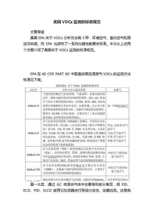
美国VOCs监测的标准规范文章导读美国EPA关于VOCs分析方法有3种:环境空气、室内空气和固定污染源。
而EPA也颁布了一系列仪器性能要求标准。
本文从上述两个方面介绍了美国关于VOCs 监测的标准规范。
EPA在40 CFR PART 60 中配套的固定源废气VOCs的监测方法标准见下表。
第一大类:通过GC将混合气体中主要有机物分离后,用FID、ECD、PID、ELCD 或其它检测器进行各组分定性、定量检测。
这是我们国内常用的GC-FID在线系统,PID也运营较多,因价格差异和效果差异巨大,一般监管单位目前在固定源上的VOCs在线监测要求均为GC-FID原理。
第二大类:总气态有机物(TOC)浓度的测定火焰离子化分析法(FIA),由加热采样管、管路、玻璃纤维过滤器和FIA 分析仪构成现场在线分析,直接连续测定TOC 浓度。
此法在国内固定源VOCs监测运营不多。
第三大类:总气态有机物(TOC)浓度的测定非分散红外分析法(NDIR)。
直接接口取样系统现场在线分析。
主要用于含烷烃的总气态有机物浓度的测定。
NDIR主要为日本技术,国内有代理商。
第四大类:抽取式傅立叶红外法(FTIR)测定气态有机、无机化合物(HAPs)。
明确水蒸气和二氧化碳是红外波段最普遍的干扰。
主要运用在厂界监测,溯源,及目前国内发展的所谓“空间立体监测”。
值得一直提的是,EPA颁布了一系列仪器性能要求标准(PerformanceSpecification, PS),其中PS8是污染源VOCs在线监测仪器的总纲,PS8A是用FID原理监测总烃仪器的技术要求,PS9针对气相色谱法监测VOCs的仪器,PS15针对傅立叶红外法监测VOCs的仪器,见下表。
素材来源:VOCs减排工作站编辑:VOCs前沿。
VOC检测方法 VOC检测项目 VOC测试标准

VOC检测方法,VOC检测项目,VOC测试标准VOC检测方法VOC是“Vehicle interior air test and test for emission of volatile organic compounds of automotive interior trims”的缩写,即车内空气及车内饰件材料有机挥发物检测。
较、乙苯、苯乙烯、甲醛、乙醇、十四碳烷、TVOC。
在世界不同的地区,挥发性有机化合物(VOC)的定义、标准和测试方法犹如百花齐放,不断变化,百家争鸣。
美国采用美国环保署(EPA)的方法24,即用热失重法测定VOC的方法(ASTM D2369测试涂料中不挥发物含量)1,2 。
ASTM D6886是另一种VOC测试方法,用于某些法规的监管,这是用气相色谱法来测定VOC含量的方法。
涂料生产商通过这些测试数据确保他们的涂料产品是否满足美国各个地区对各种待测涂料规定的限值要求。
欧盟也采用气相色谱法(ISO11890-2)VOC检测项目VOC的测试项目必须通过传导和辐射,要通过测试的注意事项需要具体的产品来说,另外VOC的测试项目还分好多标准,因为产品不同,标准不同,有什么不放心的可以找我们,协助整改,帮你顺利的通过测试。
深圳宇冠检测专业voc检测,能够对污染源排放的各种气态成份及颗粒物等进行实时监测。
测量精度高,专业,可靠,值得信赖!锅炉烟气监测,voc检测,环境检测,水质检测等。
咨询8 CMA资质认可,提供专业检测服务。
VOC测试标准通常所说的墙面漆中对人体有害的化学物质就是指VOC。
这些挥发性有机化合物包括甲醛、氨等物质。
VOC达到一定浓度时,会引起头痛、恶心等症状,甚至引发抽搐、昏迷等危害神经系统,造成记忆力减退等严重后果。
从7月1日起强制执行的涂料国标《GB18582-2001室内装饰装修材料内墙涂料中有害物质限量》中VOC含量的定义是:“涂料中总挥发物含量扣减水分含量,即为涂料中挥发性有机化合物含量。
- 1、下载文档前请自行甄别文档内容的完整性,平台不提供额外的编辑、内容补充、找答案等附加服务。
- 2、"仅部分预览"的文档,不可在线预览部分如存在完整性等问题,可反馈申请退款(可完整预览的文档不适用该条件!)。
- 3、如文档侵犯您的权益,请联系客服反馈,我们会尽快为您处理(人工客服工作时间:9:00-18:30)。
[键入文字]
美国环境挥发性有机物的检测技术
北极星VOCs 在线讯:摘要:本文简要介绍美国挥发性有机物的检测技术和检测方
法,对近年挥发性有机物的检测技术进展做了讨论,结合中国的现状,对中国在这项技术的
发展做了建议。
引言
挥发性有机物是环境污染物中非常重要的化合物,对人体健康和环境质量都有重要
影响。
挥发性有机物污染来源主要是大量生产的有机溶剂和石油制品使用,以及在生
产中特别是有机化工中产生的污染物。
挥发性有机物大多对人体有害,有一些有足够
证据可认为是致癌物质。
在工业发展过程中由于处理不当或污染防治措施缺失,有大
量挥发性有机物泄漏到土壤地下水,形成为数众多的土壤地下水的污染场点。
挥发性
有机物,在光化学反应之中使地面臭氧浓度增加、平流层臭氧层减少、也是温室气体
成分之一,对环境生态人体健康有深远的影响。
在各国环境法规对挥发有机物污染控制要求,为满足法规的要求、了解污染的状况
和污染控制的效果,需要对挥发性有机物进行检测。
本文着重对美国各种介质的挥发
性有机物的检测方法作简要介绍,对近年挥发性有机物技术发展做以讨论,根据对中
国在这方面的技术的现状的了解,对中国在这一技术的发展做了一些讨论和建议。
一、美国环境中挥发性有机物的检测技术
美国有关饮用水安全、地表水污染控制、空气质量的改善以及土壤地下水的污染治
理的法规对挥发性有机物的检测都有要求,继而发展了将了一系列检测方法。
地表水
的检测方法,直接成为美国联邦法规的环保篇的一部分(CFR40part136appendixA),在
危险废物的鉴定和管理上编制了一系列的检测方法指南
(SW4&6TestMethodsforEvaluatingSolidWaste,Phydcal/Chemical),为了追诉环境责任利用联邦政府周转基金修复污染场址的超级基金(Superfund)专门制定了对检测和数
1。
