1.25Gbps BIDI SFP 1490nmTx 1310nmRx 20Km光模块介绍
SFP-GE-BIDI-20KM-T1310 R1490-x-D10光收发模块说明书
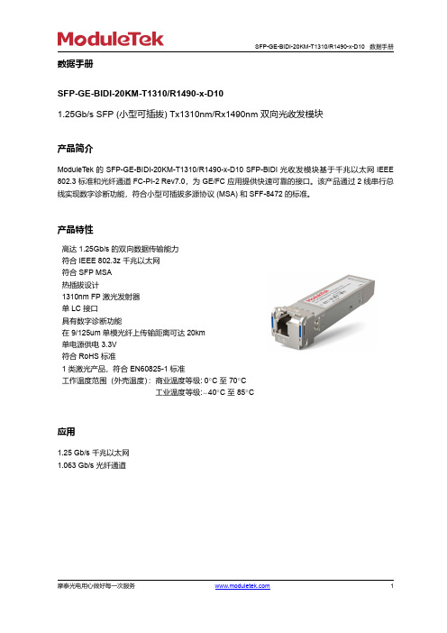
数据手册SFP-GE-BIDI-20KM-T1310/R1490-x-D101.25Gb/s SFP(小型可插拔)Tx1310nm/Rx1490nm双向光收发模块产品简介ModuleTek的SFP-GE-BIDI-20KM-T1310/R1490-x-D10SFP-BIDI光收发模块基于千兆以太网IEEE 802.3标准和光纤通道FC-PI-2Rev7.0,为GE/FC应用提供快速可靠的接口。
该产品通过2线串行总线实现数字诊断功能,符合小型可插拔多源协议(MSA)和SFF-8472的标准。
产品特性高达1.25Gb/s的双向数据传输能力符合IEEE802.3z千兆以太网符合SFP MSA热插拔设计1310nm FP激光发射器单LC接口具有数字诊断功能在9/125um单模光纤上传输距离可达20km单电源供电3.3V符合RoHS标准1类激光产品,符合EN60825-1标准工作温度范围(外壳温度):商业温度等级:0◦C至70◦C工业温度等级:−40◦C至85◦C应用1.25Gb/s千兆以太网1.063Gb/s光纤通道摩泰光电用心做好每一次服务1订购信息型号产品ID 描述拉环颜色SFP-GE-BIDI-20KM-T1310/R1490-C-D10M221501GE/FC ,SFP-BIDI ,单LC 接口,Tx1310nm/Rx1490nm ,传输距离可达20km,商业级蓝色SFP-GE-BIDI-20KM-T1310/R1490-I-D10M221502GE/FC ,SFP-BIDI ,单LC 接口,Tx1310nm/Rx1490nm ,传输距离可达20km ,工业级蓝色注:1.产品ID 为我司产品标准型号的简写订货号如需了解更多信息或订购上述产品,请联系:电子邮件:*******************摩泰光电官网:产品一般规格参数符号最小值典型值最大值单位备注数据速率DR 1.25Gb/s 1DR 1.062Gb/s2误码率BER 10−12工作温度T C 070◦C 3-4085◦C 3储存温度T STO −4085◦C4工作电流I CC 200300mA 5工作电压V CC 3.14 3.33.46V 最大电压V MAX−0.54V5注:1.IEEE 802.32.FC-PI-2Rev7.03.外壳表面温度4.环境温度5.工作电流最大值定义为满流量、模块外壳最高温度下的工作电流;传输距离数据速率光纤类型距离范围(km)备注1.25Gb/s9/125um 单模光纤20光学特性—发射机V CC=3.14V to3.46V,T C参数符号最小值典型值最大值单位备注发射光功率P TX-9-3dBm1光中心波长λC126013101360nm消光比ER9dB光谱宽度(RMS)Δλ5nm光信号上升/下降时间t r/t f250300ps(20%-80%)注:1.1类产品典型光眼图使用1.25Gb/s,PRBS27-1信号测试光学特性—接收机V CC=3.14V to3.46V,T C参数符号最小值典型值最大值单位备注接收机过载P OL0dBm光中心波长λC147014901510nm接收灵敏度R X SEN−23dBm1回波损耗ORL14dBmLOS信号生效LOS A−35dBmLOS信号失效LOS D−24dBmLOS信号迟滞区间LOS H0.5dB注:1.用PRBS27-1测试模式测量,BER<10−12;电气特性—发射机V CC=3.14V to3.46V,T C参数符号最小值典型值最大值单位备注差分输入阻抗R IN100Ω单端输入摆幅V IN PP2501200mV发射机关闭电压V D V CC-1.3V CC V发射机使能电压V EN V EE V EE+0.8V电气特性—接收机V CC=3.14V to3.46V,T C参数符号最小值典型值最大值单位备注单端输出摆幅V OUT PP300400800mV输出信号上升时间/下降时间t r/t f300ps(20%-80%)LOS信号生效V LOS A V CC−0.5V CC HOST VLOS信号失效V LOS D V EE V EE+0.5V 接收端压制功能压制功能的判断方式备注关闭N.AA0H 设备的寄存器说明IIC 地址字节大小寄存器名称寄存器描述取值(HEX)01IdentifierSFP 0311Extended Identifier使用IIC 接口0421Connector使用LC 连接器073-108Transceiver 1000BASE-BX10-U 0000004000000000111Encoding 使用8B/10B 编码方式01121BR,Nominal 1.25Gb/s 的标称速率0D 131Rate Identifier 无速率选择功能00141Length(9μm)-km 在单模光纤传输20km 14151Length (9μm)-100m 在单模光纤传输20km C8161Length (50μm)-10m 在多模光纤的传输距离00171Length (62.5μm)-10m 在多模光纤的传输距离00181Length (Copper)在铜缆的传输距离00191Reserved 未定义0020-3516厂商名称MODULETEKASCII Format361Transceiver 未定义0037-393Vendor OUI 厂商IEEE 公司ID 00000040-5516Vendor PN厂商产品型号由厂商定义56-594Vendor Revision Number厂商产品版本号由厂商定义60-612Wavelength 激光器的波长1310纳米051E 621Reserved 未定义00631CC_BASE 0-62字节的校验和由厂商定义64-652Transceiver Options1.Rx_LOS 信号监控2.Tx_FAULT 信号监控3.Tx_DIS 信号监控001A 661BR,max 高比特率余量00671BR,min 低比特率余量0068-8316Vendor SN 厂商序列号由厂商定义84-918Date code 日期代码由厂商定义921Monitoring TypeDOM 信息内部校准接收光功率测量使用平均光功率68931Enhanced Options 1.发射光与接收光Alarm 与Warning 监控2.Tx_DIS 信号监控与控制3.Rx_LOS 信号监控4.Tx_FAULT 信号监控F0941Compliance 按照12.0版本的SFF-8472定义08951CC_EXT 64-94字节的校验和由厂商定义96-12732Vendor Specific 厂商自定义区域由厂商定义128-255128Vendor Specific厂商自定义区域由厂商定义数字诊断功能SFP-GE-BIDI-20KM-T1310/R1490-x-D10支持SFP MSA中定义的2线串行通信协议,该产品通过地址为0xA2的2线接口访问数字诊断信息。
CiSCO光模块型号
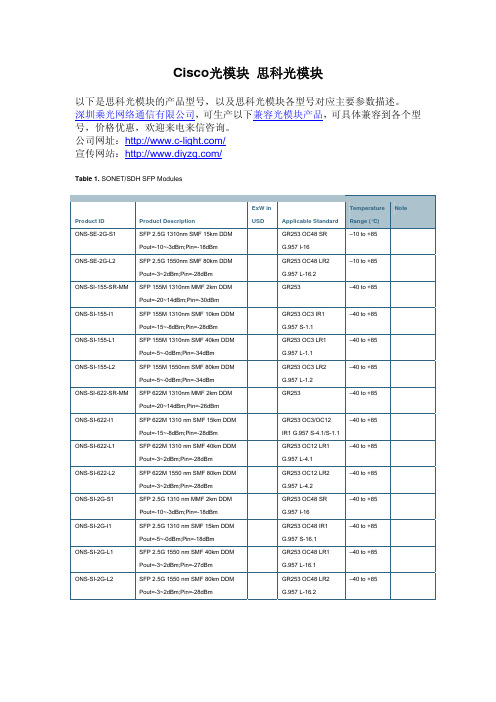
Cisco光模块思科光模块以下是思科光模块的产品型号,以及思科光模块各型号对应主要参数描述。
深圳乘光网络通信有限公司,可生产以下兼容光模块产品,可具体兼容到各个型号,价格优惠,欢迎来电来信咨询。
公司网址:/宣传网站:/Table 1. SONET/SDH SFP ModulesProduct ID Product Description ExW inUSD ApplicableStandardTemperatureRange (°C)NoteONS-SE-2G-S1 SFP 2.5G 1310nm SMF 15km DDMPout=-10~-3dBm;Pin=-18dBm GR253 OC48 SRG.957 I-16–10 to +85ONS-SE-2G-L2 SFP 2.5G 1550nm SMF 80km DDMPout=-3~2dBm;Pin=-28dBm GR253 OC48 LR2G.957 L-16.2–10 to +85ONS-SI-155-SR-MM SFP 155M 1310nm MMF 2km DDMPout=-20~14dBm;Pin=-30dBmGR253 –40 to +85ONS-SI-155-I1 SFP 155M 1310nm SMF 10km DDMPout=-15~-8dBm;Pin=-28dBm GR253 OC3 IR1G.957 S-1.1–40 to +85ONS-SI-155-L1 SFP 155M 1310nm SMF 40km DDMPout=-5~-0dBm;Pin=-34dBm GR253 OC3 LR1G.957 L-1.1–40 to +85ONS-SI-155-L2 SFP 155M 1550nm SMF 80km DDMPout=-5~-0dBm;Pin=-34dBm GR253 OC3 LR2G.957 L-1.2–40 to +85ONS-SI-622-SR-MM SFP 622M 1310nm MMF 2km DDMPout=-20~14dBm;Pin=-26dBmGR253 –40 to +85ONS-SI-622-I1 SFP 622M 1310 nm SMF 15km DDMPout=-15~-8dBm;Pin=-28dBm GR253OC3/OC12IR1 G.957 S-4.1/S-1.1–40 to +85ONS-SI-622-L1 SFP 622M 1310 nm SMF 40km DDMPout=-3~2dBm;Pin=-28dBm GR253 OC12 LR1G.957 L-4.1–40 to +85ONS-SI-622-L2 SFP 622M 1550 nm SMF 80km DDMPout=-3~2dBm;Pin=-28dBm GR253 OC12 LR2G.957 L-4.2–40 to +85ONS-SI-2G-S1 SFP 2.5G 1310 nm MMF 2km DDMPout=-10~-3dBm;Pin=-18dBm GR253 OC48 SRG.957 I-16–40 to +85ONS-SI-2G-I1 SFP 2.5G 1310 nm SMF 15km DDMPout=-5~-0dBm;Pin=-18dBm GR253 OC48 IR1G.957 S-16.1–40 to +85ONS-SI-2G-L1 SFP 2.5G 1550 nm SMF 40km DDMPout=-3~2dBm;Pin=-27dBm GR253 OC48 LR1G.957 L-16.1–40 to +85ONS-SI-2G-L2 SFP 2.5G 1550 nm SMF 80km DDMPout=-3~2dBm;Pin=-28dBm GR253 OC48 LR2G.957 L-16.2–40 to +85Table 2. Data SFP ModulesProduct ID Product Description ExW inUSD Applicable StandardTemperatureRange (°C)NoteONS-SE-100-LX10 SFP 100M 1310 nm SMF 10km DDMPout=-15~-8dBm;Pin=-28dBm 100Base LX IEEE-802.3–10 to +85ONS-SI-100-LX10 SFP 100M 1310 nm SMF 10km DDMPout=-15~-8dBm;Pin=-28dBm 100Base LX IEEE-802.3–40 to +85ONS-SE-100-FX SFP 100M 1310 nm MMF 2km DDMPout=-20~14dBm;Pin=-31dBm 100Base FX IEEE-802.3–10 to +85ONS-SI-100-FX SFP 100M 1310 nm MMF 2km DDMPout=-20~14dBm;Pin=-31dBm 100Base FX IEEE-802.3–40 to +85ONS-SE-100-BX10U SFP 100M Tx:1310nm,RX:1490/1550nm DDMPout=-14~-8dBm;Pin=-28.2dBm 100Base BX-U IEEE-802.3–10 to +85ONS-SE-100-BX10D SFP 100M Tx:1490/1550nm,RX:1310nm DDMPout=-14~-8dBm;Pin=-28.2dBm 100Base BX-D IEEE-802.3–10 to +85ONS-SC-GE-SX SFP 1.25G 850nm MMF 550m DDMPout=-9.5~-0dBm;Pin=-17dBm 1000Base SX IEEE-802.30 to +70ONS-SI-GE-SX SFP 1.25G 850nm MMF 550m DDMPout=-9.5~0dBm;Pin=-17dBm 1000Base SX IEEE-802.3–40 to +85ONS-SC-GE-LX SFP 1.25G 1310nm SMF 10km DDMPout=-9.5~-3dBm;Pin=-19dBm 1000Base LX IEEE-802.30 to +70ONS-SI-GE-LX SFP 1.25G 1310nm SMF 10km DDMPout=-9.5~-3dBm;Pin=-19dBm 1000Base SX IEEE-802.3–40 to +85ONS-SE-G2F-SX SFP GE/1G-FC/2G-FC 850nm MMF 550m DDMPout=-9.5~0dBm;Pin=-17dBm 1000BaseSXIEEE-802.3,100-M5-SN-I 100-M6-SN-I200-M5-SN-I 200-M6-SN-I–10 to +85ONS-SE-G2F-LX SFP GE/1G-FC/2G-FC 1310nm SMF 10kmDDMPout=-9.5~-3dBm;Pin=-19dBm 1000BaseLXIEEE-802.3,100-SM-LC-L 200-SM-LC-L–10 to +85ONS-SI-GE-ZX SFP 1.25G 1550nm SMF 80km DDMPout=-0~5dBm;Pin=-23dBm 1000Base ZX IEEE-802.3–40 to +85ONS-SE-GE-ZX SFP 1.25G 1550nm SMF 80km DDMPout=-0~5dBm;Pin=-23dBm 1000Base ZX IEEE-802.3–10 to +85ONS-SE-4G-MM SFP 4G 850nm MMF 550m DDMPout=-9~-3.5dBm;Pin=-15dBm 400-M5-SN-I and 400-M6-SN-I–10 to +85ONS-SE-4G-SM SFP 4G 1310nm SMF 10km DDMPout=-8.4~-3dBm;Pin=-15dBm 400-SM-LC-L–10 to +85Electrical SFP ModulesProduct ID Product Description ExW inUSDApplicableStandardTemperatureRange (°C)NoteONS-SE-ZE-EL SFP – 10/100/1000 Ethernet BaseTMultirate Copper RJ-45IEEE-802.3 –10 to +85ONS-SC-155-EL SFP – STM1 Electrical ITU-T G.703 (ES1) 0 to +70 Multirate SFP ModulesProduct ID Product Description ExW inUSDApplicableStandardTemperatureRange (°C)NoteONS-SE-Z1 SFP 2.5G 1310nm SFM 15km DDMPout=-5~0dBm;Pin=-18dBm(OC-48/STM-16)Pin=-22 (GE)Pin=-23 (OC-12/STM-4)/ (OC-3/STM-1) 1000BaseLXIEEE-802.3,GR253 OC48 IR1OC12 SR ,OC3 SRG.957 S-16.1,I-4.1,I-1.1–10 to +85CWDM SFP ModulesProduct ID Product Description ExW in USD Applicable Standard TemperatureRange (°C)NoteONS-SE-155-1470 SFP 155M 1470nm SMF 80km DDMPout=0~5dBm;Pin=-34dBmITU-T G.694.2 –10 to +85ONS-SE-155-1490 SFP 155M 1490nm SMF 80km DDMPout=0~5dBm;Pin=-34dBmITU-T G.694.2 –10 to +85ONS-SE-155-1510 SFP 155M 1510nm SMF 80km DDMPout=0~5dBm;Pin=-34dBmITU-T G.694.2 –10 to +85ONS-SE-155-1530 SFP 155M 1530nm SMF 80km DDMPout=0~5dBm;Pin=-34dBmITU-T G.694.2 –10 to +85ONS-SE-155-1550 SFP 155M 1550nm SMF 80km DDMPout=0~5dBm;Pin=-34dBmITU-T G.694.2 –10 to +85ONS-SE-155-1570 SFP 155M 1570nm SMF 80km DDMPout=0~5dBm;Pin=-34dBmITU-T G.694.2 –10 to +85ONS-SE-155-1590 SFP 155M 1590nm SMF 80km DDMPout=0~5dBm;Pin=-34dBmITU-T G.694.2 –10 to +85ONS-SE-155-1610 SFP 155M 1610nm SMF 80km DDMPout=0~5dBm;Pin=-34dBmITU-T G.694.2 –10 to +85ONS-SE-622-1470 SFP 622M 1470nm SMF 80km DDMPout=0~5dBm;Pin=-28dBmITU-T G.694.2 –10 to +85ONS-SE-622-1490 SFP 622M 1490nm SMF 80km DDMPout=0~5dBm;Pin=-28dBmITU-T G.694.2 –10 to +85ONS-SE-622-1510 SFP 622M 1510nm SMF 80km DDMPout=0~5dBm;Pin=-28dBmITU-T G.694.2 –10 to +85ONS-SE-622-1530 SFP 622M 1530nm SMF 80km DDMPout=0~5dBm;Pin=-28dBmITU-T G.694.2 –10 to +85ONS-SE-622-1550 SFP 622M 1550nm SMF 80km DDMPout=0~5dBm;Pin=-28dBmITU-T G.694.2 –10 to +85ONS-SE-622-1570 SFP 622M 1570nm SMF 80km DDMPout=0~5dBm;Pin=-28dBmITU-T G.694.2 –10 to +85ONS-SE-622-1590 SFP 622M 1590nm SMF 80km DDMPout=0~5dBm;Pin=-28dBmITU-T G.694.2 –10 to +85ONS-SE-622-1610 SFP 622M 1610nm SMF 80km DDMPout=0~5dBm;Pin=-28dBmITU-T G.694.2 –10 to +85ONS-SC-Z3-1470 SFP 1.25G 1470nm SMF 80km DDMPout=0~4dBm;Pin=-28dBmITU-T G.694.2 0 to +70ONS-SC-Z3-1490 SFP 1.25G 1490nm SMF 80km DDMPout=0~4dBm;Pin=-28dBmITU-T G.694.2 0 to +70ONS-SC-Z3-1510 SFP 1.25G 1510nm SMF 80km DDMPout=0~4dBm;Pin=-28dBmITU-T G.694.2 0 to +70ONS-SC-Z3-1530 SFP 1.25G 1530nm SMF 80km DDMPout=0~4dBm;Pin=-28dBmITU-T G.694.2 0 to +70ONS-SC-Z3-1550 SFP 1.25G 1550nm SMF 80km DDMPout=0~4dBm;Pin=-28dBmITU-T G.694.2 0 to +70ONS-SC-Z3-1570 SFP 1.25G 1570nm SMF 80km DDMPout=0~4dBm;Pin=-28dBmITU-T G.694.2 0 to +70ONS-SC-Z3-1590 SFP 1.25G 1590nm SMF 80km DDMPout=0~4dBm;Pin=-28dBmITU-T G.694.2 0 to +70ONS-SC-Z3-1610 SFP 1.25G 1610nm SMF 80km DDMPout=0~4dBm;Pin=-28dBmITU-T G.694.2 0 to +70 XFP List and Description Grey XFP ModulesProduct ID Product Description ExW inUSD Applicable StandardTemperatureRange (°C)NoteONS-XC-10G-S1 XFP 10G 1310nm SMF 10km DDMPout=-6~1dBm(-8.2~0.5dBm);Pin=-11dBm(-14.4dBm) ITU G694 I-64.1 GR253SR-1 10GE BASE LR1200-SM-LL-L0 to +70ONS-XC-10G-I2XFP 10G 1550nm SMF 40km ITU G694 S-64.2b0 to +70Pout=-1~2dBm;Pin=-14dBm GR253IR-2ONS-XC-10G-L2 XFP 10G 1550nm SMF 80kmPout=0~4dBm;Pin=-24dBm ITU G959.1 P1L1-2D2GR253 LR-20 to +70DWDM XFP ModulesNote:” XX.X”ranges from 30.3 to 61.4.Product ID Product Description ExW inUSD Applicable StandardTemperatureRange (°C)NoteONS-XC-10G-XX.X XFP 10G 15XX.X SMF 80km DDMPout=-1~3dBmITU G694, GR2918 0 to +70 GLC ModulesProduct ID Product Description ExW inUSD Applicable StandardTemperatureRange (°C)NoteGLC-FE-100FX SFP 155M 1310nm MMF 2kmPout= -8~-15dBm ; Pin= -30dBm FastEthernet;SDH/STM-1; OC3 SR0 to 75GLC-FE-100LX SFP 155M 1310nm SMF 10kmPout= -8~-15dBm ; Pin= -30dBm Fast Ethernet; SDH/STMI-1; OC3 IR10 to 75GLC-FE-100EX SFP 155M EX 1310nm SMF 40kmPout= -8~-15dBm ; Pin= -28dBm Fast Ethernet; SDH/STML-1.1; OC3 LR10 to 75GLC-FE-100ZX SFP 155M 1550nm SMF 80kmPout= -5~0dBm ; Pin= -32dBm Fast Ethernet; SDH/STML-1.2; OC3 LR20 to 75GLC-FE-100FX-RGD SFP 155M 1310nm MMF 2kmPout= -8~-15dBm ; Pin= -30dBm FastEthernet;SDH/STM-1; OC3 SR-40 to 85GLC-FE-100LX-RGD SFP 155M 1310nm SMF 10kmPout= -8~-15dBm ; Pin= -30dBm Fast Ethernet; SDH/STMI-1; OC3 IR1-40 to 85GLC-FE-100EX-RGD SFP 155M EX 1310nm SMF 40kmPout= -8~-15dBm ; Pin= -28dBm Fast Ethernet; SDH/STML-1.1; OC3 LR1-40 to 85GLC-FE-100BX-D SFP 100M Tx: 1550nm,RX: 1310nm 20km Fast Ethernet; SDH/STMI-1.1; OC3 IR10 to 75GLC-FE-100BX-U SFP 100M Tx:1310nm,RX: 1550nm 20km Fast Ethernet; SDH/STMI-1.1; OC3 IR10 to 75GLC-SX-MM SFP 1.25G 850nm MMF 550mPout= -3~-9dBm ; Pin= -18dBm 1.25G1000BaseSX;1.06G FC SX0 to 75GLC-LH-SM SFP 1.25G 1310nm SMF 10kmPout= -3~-9dBm ; Pin= -20dBm 1.25G1000BaseLX;1.06G FC LX0 to 75GLC-EX-SMD SFP 1.25G 1310nm SMF 40km DDMPout= -5~0dBm ; Pin= -22dBm 1.25G1000BaseEX;1.06G FC EX0 to 75GLC-ZX-SM SFP 1.25G 1550nm SMF 80kmPout= 0~5dBm ; Pin= -23dBm 1.25G1000BaseZX;1.06G FC ZX0 to 75GLC-T SFP 100M/1000M TX 100m max 1.25G 1000BaseTX 0 to 75GLC-SX-MM-RGD SFP 1.25G 1310nm SMF 10kmPout= -3~-9dBm ; Pin= -20dBm 1.25G1000BaseLX;1.06G FC LX-40 to 85GLC-LH-SM-RGD SFP 1.25G 1310nm SMF 40km DDMPout= -5~0dBm ; Pin= -22dBm 1.25G1000BaseEX;1.06G FC EX-40 to 85GLC-ZX-SM-RGD SFP 1.25G 1550nm SMF 80kmPout= 0~5dBm ; Pin= -23dBm 1.25G1000BaseZX;1.06G FC ZX-40 to 85CWDM-SFP-**** SFP1.25GCWDM 1XX0nm SMF 80kmDDM Pout= 0~5dBm ; Pin= -23dBm 1.25G1000BaseCWDM;1.06G FC CWDM0 to 75GLC-BX-D SFP 1000M Tx: 1550nm,RX: 1310nm20km 1.25G1000BaseLX;1.06G FC LX0 to 75GLC-BX-U SFP 1000M Tx:1310nm,RX: 1550nm20km 1.25G1000BaseLX;1.06G FC LX0 to 75XFP-10G-MM-SR XFP 10G SR/SW 850nm MMF 300m DDMPout= -5~-1dBm ; Pin= -11dBm 10GBase SR/SW 10GE;SDH/STM64 OC1920 to 75XFP-10GLR-OC192S R XFP 10G LR/LW 1310nm SMF 10kmDDM Pout= -6~-1dBm ; Pin= -13dBm10GBase LR/LW 10GE;SDH/STM64 OC1920 to 75XFP-10GER-192IR XFP 10G ER/EW 1550nm SMF 40kmDDM Pout= -1~2dBm ; Pin= -16dBm 10GBase ER/EW 10GE;SDH/STM64 OC1920 to 75XFP-10GZR-OC192L R XFP 10G ZR/ZW 1550nm SMF 80kmDDM Pout= 0~4dBm ; Pin= -23dBm10GBaseZR/ZW10GE;SDH/STM64 OC1920 to 75DWDM-XFP-**** DWDM XFP C-Band SMF 80km DDMPout= 0~4dBm ; Pin= -23dBm 10GBaseZR/ZW10GE;SDH/STM64 OC1920 to 75XENPAK-10GB-SR Xenpak 10G SR 850nm MMF 85m DDMPout= -5~-1dBm ; Pin= -11dBm 10GBase SR 10GEthernet0 to 75XENPAK-10GB-LR Xenpak 10G LR 1310nm SMF 10km DDMPout= -8~0dBm ; Pin= -12dBm 10GBase LR 10GEthernet0 to 75XENPAK-10GB-LR+ Xenpak 10G LR 1310nm SMF 10km DDMPout= -8~0dBm ; Pin= -12dBm 10GBase LR 10GEthernet0 to 75X2-10GB-SR X2 10G SR/SW 850nm MMF 85m DDMPout= -5~-1dBm ; Pin= -11dBm 10GBase SR/SW 10GEthernet0 to 75X2-10GB-LR X2 10G LR/LW 1310nm SMF 10km DDMPout= -8~0dBm ; Pin= -11dBm 10GBase LR/LW 10GEthernet0 to 75X2-10GB-LRM X2 10G LRM 1310nm MMF 220m DDMPout= -6~0dBm ; Pin= -8dBm 10GBaseLRM10GEthernet0 to 75X2-10GB-ER X2 10G ER/EW 1550nm SMF 40km DDMPout=-4~4dBm ; Pin= -16dBm 10GBase ER/EW 10GEthernet0 to 75SFP-10G-SR SFP+ 10G SR/SW 850nm MMF 300mDDM Pout= -9~-1dBm ; Pin= -13dBm 10GBase SR/SW 10GEthernet0 to 75SFP-10G-LR SFP+ 10G LR/LW 1310nm SMF 10kmDDM Pout= -8~0dBm ; Pin= -14dBm 10GBase LR/LW 10GEthernet0 to 75SFP OC ModulesProduct ID Product Description ExW inUSD Applicable StandardTemperatureRange (°C)NoteSFP-OC3-MM OC-3/STM-1 SFP 2 km 1310nm MMF FastEthernet;SDH/STM-1; OC3 SR0 to 75SFP-OC3-SR SFP 155M 1310nm MMF 2kmPout= -8~-15dBm ; Pin= -30dBm FastEthernet;SDH/STM-1; OC3 SR0 to 75SFP-OC3-IR1 SFP155M 1310nm SMF 10kmPout= -8~-15dBm ; Pin= -30dBm Fast Ethernet; SDH/STMI-1; OC3 IR10 to 75SFP-OC3-LR1 SFP 155M EX 1310nm SMF 40kmPout= -8~-15dBm ; Pin= -28dBm Fast Ethernet; SDH/STML-1.1; OC3 LR10 to 75SFP-OC3-LR2 SFP 155M 1550nm SMF 80kmPout= -5~0dBm ; Pin= -32dBm Fast Ethernet; SDH/STML-1.2; OC3 LR20 to 75SFP-OC12-MM OC-12/STM-4 SFP 2 km 1310nm MMF SDH/STMS-4.1I-4;OC12, SR0 to 75 SFP-OC12-SR OC-12/STM-4 SFP 2 km 1310nm MMF SDH/STMS-4.1I-4;OC12, SR0 to 75SFP-OC12-IR1 SFP 622M IR 1310nm SMF 15kmPout= -8~-15dBm ; Pin= -28dBm SDH/STMS-4.1I-4;OC12 IR-1, SR0 to 75SFP-OC12-LR1 SFP 622M LR1 1310nm SMF 40kmPout= -8~-14dBm ; Pin= -28dBm SDH/STM L-4.1; OC12LR-10 to 75SFP-OC12-LR2 SFP 622M LR2 1550nm SMF 80kmPout= -3~2dBm ; Pin= -28dBm SDH/STM L-4.2; OC12LR-20 to 75SFP-OC48-SR OC-48/STM-16 SFP 2 km 1310nm MMF SDH/STMS-16.1;OC48,SR0 to 75SFP-OC48-IR1 SFP2.5G IR 1310nm SMF 15kmPout= -5~0dBm ; Pin= -20dBm SDH/STMS-16.1;OC48 IR-1, SR0 to 75SFP-OC48-LR1 SFP 2.5G LR1 1550nm SMF 40kmPout= 0~5dBm ; Pin= -20dBm SDH/STML-16.1;OC48LR-10 to 75SFP-OC48-LR2 SFP 2.5G LR2 1550nm SMF 80kmPout= 0~5dBm ; Pin= -30dBm SDH/STML-16.2;OC48LR-20 to 75DS SFP ModulesProduct ID Product Description ExW inUSD Applicable StandardTemperatureRange (°C)NoteDS-SFP-FCGE-SW SFP 1000M SX 850nm MMF 550m DDMPout= -3~-9dBm ; Pin= -18dBm 1.25G1000BaseSX;1.06G FC SX-10 to 85DS-SFP-FCGE-LW SFP 1000M LX 1310nm SMF 10km DDMPout= -3~-9dBm ; Pin= -20dBm 1.25G1000BaseLX;1.06G FC LX-10 to 85DS-SFP-FCGE-EW SFP 1000M EX 1310nm SMF 40km DDMPout= -5~0dBm ; Pin= -22dBm 1.25G1000BaseEX;1.06G FC EX-10 to 85DS-SFP-FCGE-ZW SFP 1000M ZX 1550nm SMF 80km DDMPout= 0~5dBm ; Pin= -23dBm 1.25G1000BaseZX;1.06G FC ZX-10 to 85DS-SFP-FC-2G-SW SFP 2G SX 850nm MMF 550m DDM 2G FC SX -10 to 85 DS-SFP-FC-2G-LW SFP2G LX 1310nm SMF 10km DDM 2G FC LX -10 to 85 DS-SFP-FC-2G-EW SFP 2G EX 1310nm SMF 40km DDM 2G FC EX -10 to 85 DS-SFP-FC-2G-ZW SFP 2G ZX 1550nm SMF 80km DDM 2G FC ZX -10 to 85。
光模块分类
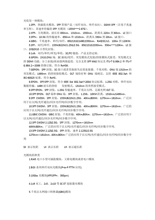
光收发一体模块:1.SFP:热插拔光模块,SFP常规产品(双纤双向、单纤双向)、SGMII SFP(百兆千兆速率互转)、多速率传输的SFP光模块(155M~~~2.67G)。
2.XFP:万兆模块,波长有850nm、1310nm、1550nm,距离从220m到80km,LC接口3.SFP+:10.3G的传输速率,850nm和1310nm,距离从330m到20km,LC接口。
4.GBIC:千兆速率,单纤/双纤,850/1310/1490/1550nm,RJ45/SC/LC,100m到120KM。
5.SFF:双纤/单纤,155M/622M/1.25G/2.5G,850/1310/1550nm,550m~~~120Km,LC接口,2X5/2X10小型化封装。
6.1x9:双纤/单纤/单发/单收,SC/FC链接,产品支持定制。
6.GPON:2X10,ONU端,SC插座/尾纤,突发模块式发射/持续模块式接受,突发模式支持DDMI功能,分工业级/商业级两级温度,完全支持SFF MAS协议及ITU-T G.984.2和ITU-TG.984.2—2006的修订版,符合RoHS6。
7.GEPON:SFP封装,SC接口或者其他损失还原连接器,千兆对称,ONU端1310nm的突发模式,1490nm的持续接收模式,OLT端恰好和ONU端相反,支持IEEE 802.3ah 和IEC-60825标准,符合RoHS。
8.EPON:SFF/SFP封装,符合IEEE Std 802.3ah?-2004协议标准,1.25G对称,单纤双向数据传输,1490波长的持续发射模式,1310nm的突然接受模式。
9.SFP EPON:SFP封装,1.25G传输速率,千兆以太网,无源光网OLT端。
10.SFF EPON:OLT端和ONU端,SFF封装,1.25G,10KM距离,1310nm/1490nm。
9.SFP CWDM:SFP封装,155M/622M/1.25G,40Km/80KM,1270nm—1610nm,广泛应用于以太网/光纤通信/同步光纤网/同步数字序列。
华为光模块属性
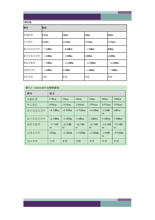
交换机常用模块:
倚窗远眺,目光目光尽处必有一座山,那影影绰绰的黛绿色的影,是春天的颜色。
周遭流岚升腾,没露出那真实的面孔。
面对那流转的薄雾,我会幻想,那里有一个世外桃源。
在天阶夜色凉如水的夏夜,我会静静地,静静地,等待一场流星雨的来临…
许下一个愿望,不乞求去实现,至少,曾经,有那么一刻,我那还未枯萎的,青春的,诗意的心,在我最美的年华里,同星空做了一次灵魂的交流…
秋日里,阳光并不刺眼,天空是一碧如洗的蓝,点缀着飘逸的流云。
偶尔,一片飞舞的落叶,会飘到我的窗前。
斑驳的印迹里,携刻着深秋的颜色。
在一个落雪的晨,这纷纷扬扬的雪,飘落着一如千年前的洁白。
窗外,是未被污染的银白色世界。
我会去迎接,这人间的圣洁。
在这流转的岁月里,有着流转的四季,还有一颗流转的心,亘古不变的心。
7.中国移动-TD-LTE光链路开通指导
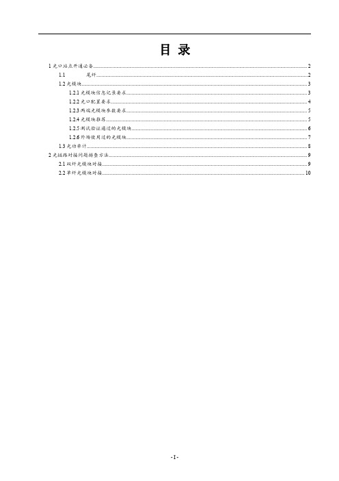
目录1光口站点开通必备 (2)1.1尾纤 (2)1.2光模块 (3)1.2.1光模块信息记录要求 (3)1.2.2光口配置要求 (4)1.2.3两端光模块参数要求 (5)1.2.4光模块推荐 (5)1.2.5测试验证通过的光模块 (6)1.2.6外场使用过的光模块 (7)1.3光功率计 (8)2光链路对接问题排查方法 (9)2.1双纤光模块对接 (9)2.2单纤光模块对接 (10)一体化皮基站支持光口开通,为方便区域同事开站及排查开站时经常出现的光链路异常问题,特写此文档,区域同事遇到光链路问题可参考此文档排查思路进行排查,如有疑义,请联系技术部。
1光口站点开通必备1.1尾纤尾纤铺设时避免存在弯折的现象,尾纤接头要注意防尘,避免因接头沾染灰尘导致光衰过大的现象。
(1)需要跳纤LC-FC(小圆转小方),用于落地PTN至基站间跳接。
(2)不需要跳纤不需要跳纤时,建议采用定制铠装尾纤,有黑色保护套,双芯,两边为LC/UPC(小方头)。
1.2光模块光模块用于光信号的传输,传输媒质为光纤。
光纤传输方式损耗低,传输距离远,在长距离传输方面具有很强的优势。
设备支持多款不同规格的光模块,用户可以根据自己的需要选择合适的光模块,通过光纤进行数据传输。
传输速率:指每秒传输比特数,单位Mbps或Gbps。
TD-LTE制式基站设备所支持光模块传输速率为:100Mbps、1Gbps传输距离:分为短距和长距两种。
一般认为2km及以下的为短距离,10km 的为长距离。
光模块的传输距离受到限制,主要是因为光信号在光纤中传输时会有一定的损耗和色散。
工作波长:指光信号传输所使用的光波段。
目前常用的光模块的工作波长主要有三种:850nm波段、1310nm波段以及1550nm波段。
光纤模式(Fiber Mode):按光在光纤中的传输模式可将光纤分为单模光纤和多模光纤两种。
多模光纤(MMF,Multi Mode Fiber)纤芯较粗,可传多种模式的光。
1.25G GBIC光模块 Tx1310nmRx1550nm
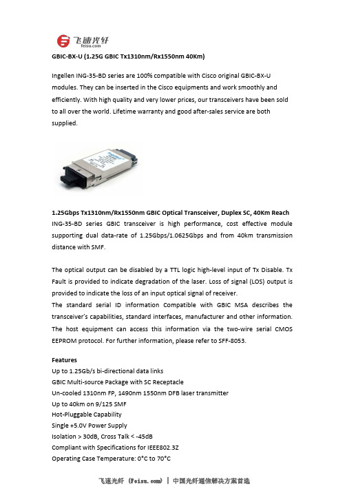
GBIC-BX-U(1.25G GBIC Tx1310nm/Rx1550nm40Km)Ingellen ING-35-BD series are100%compatible with Cisco original GBIC-BX-U modules.They can be inserted in the Cisco equipments and work smoothly and efficiently.With high quality and very lower prices,our transceivers have been sold to all over the world.Lifetime warranty and good after-sales service are both supplied.1.25Gbps Tx1310nm/Rx1550nm GBIC Optical Transceiver,Duplex SC,40Km Reach ING-35-BD series GBIC transceiver is high performance,cost effective module supporting dual data-rate of1.25Gbps/1.0625Gbps and from40km transmission distance with SMF.The optical output can be disabled by a TTL logic high-level input of Tx Disable.Tx Fault is provided to indicate degradation of the laser.Loss of signal(LOS)output is provided to indicate the loss of an input optical signal of receiver.The standard serial ID information Compatible with GBIC MSA describes the transceiver’s capabilities,standard interfaces,manufacturer and other information. The host equipment can access this information via the two-wire serial CMOS EEPROM protocol.For further information,please refer to SFF-8053.FeaturesUp to1.25Gb/s bi-directional data linksGBIC Multi-source Package with SC ReceptacleUn-cooled1310nm FP,1490nm1550nm DFB laser transmitterUp to40km on9/125SMFHot-Pluggable CapabilitySingle+5.0V Power SupplyIsolation>30dB,Cross Talk<-45dBCompliant with Specifications for IEEE802.3ZOperating Case Temperature:0°C to70°CApplicationsGigabit EthernetFiber ChannelWDM ApplicationSpecificationForm Factor BIDI GBIC Distance40km Data Rate 1.25G Low End Case Temperature(°C)0°C High End Case Temperature(°C)70°C Diagnostics Digital Transmitter DFB Receiver PIN Wavelength(nm)1310/1550 Connector SC。
SFP光模块及光接收器知识介绍
光模块发展历史
封装形式:1X9 SFF GBIC SFP, XFP, SFP+ 传输速率:155M,622M 1.25G,2.5G 4.25G, 8.5G, 10G, 40G 光接口形式:尾纤型(Pigtail);插拔型(Receptacle) 光传输形式:双纤双向(MSA);单纤双向(BiDi) 接入应用:P to P P to MP: PON (GE-PON, GPON, WDM-PON) 功能:不带监控功能(None DDM) 带数字诊断功能(DDM)
27
精选2021版课件
主要内容
➢光模块简介 ➢光模块内部主要元器件 ➢光模块调制方式 ➢光模块的特点及应用 ➢光模块原理框图 ➢光模块主要性能指标 ➢光模块接口电平
28
精选2021版课件
调制方式
➢ 直接调制 ➢ 外调制
EA调制(Electroabsorption Modulator) MZ调制(Mach-Zehnder Modulator)
35
精选2021版课件
SFF模块
特点: ➢ 工作速率:155Mb/s~ 2.5Gb/s ➢ 工作电压:3.3 V ➢ 波长:850nm,1310nm,1550nm ➢ 宽温工作范围 ➢ 传输距离可达80km ➢ 带数字诊断功能(部分) 应用:
➢ 数据通信:快速以太网,千兆以太网,1x/2x/4x 光纤 通道
1X9光模块
特点: ➢ 工作速率: 155Mb/s~1Gb/s ➢ 工作电压:3.3 V或5V ➢ 波长:1310nm,1550nm ➢ 宽温工作范围 ➢ 传输距离可达80km 应用 ➢ 数据通信:快速以太网,千兆以太网 ➢ 电信: OC -3/STM -1, OC -12/STM -4
34
带你认识SFP光模块、SFP+光模块
带你认识SFP光模块、SFP+光模块今天主要跟大家聊聊SFP光模块与SFP+光模块的主要知识,希望能够对大家更好地认识这两款光模块有所帮助。
一,概念(1)SFP光模块全称Small Form-Factor Pluggable,即:小型热插拔光收发一体模块。
虽然SFP模块体积比GBIC模块小一半,只有大拇指大小,但它却可以在相同的面板上配置多出一倍以上的端口数量。
SFP模块的其他功能基本和GBIC一致。
有些交换机厂商称SFP模块为小型化GBIC(MINI-GBIC)。
(2)SFP+光模块用于10Gbps以太网和8.5Gbps光纤通道(Fibre Channel)系统的最新可插拔光纤模块。
SFP+具有比X2和XFP封装更紧凑的外形尺寸,且功耗不到1W。
此外,它可提供比10Gbps器件更高的安装密度。
二,构成(1)SFP光模块SFP光模块由激光器(包括发射器TOSA跟接收器ROSA)和线路板IC及外部配件构成,外部配件则有外壳、底座、PCBA、拉环、卡扣、解锁件、橡胶塞组成,为了辨认方便一般以拉环的颜色辨别模块的参数类型。
(2)SFP+光模块SFP+光模块属于SFP光模块系列,其构成与SFP光模块类似。
SFP+光模块把用于时钟和数据恢复的电路从芯片中转移到线卡上,把线卡的密度从XFP的每块16个提高到24个,做到了真正的降低成本。
三,分类(1)SFP光模块①按照速率分:有155M/622M/1.25G/2.125G/4.25G/8G/10G,其中155M和1.25G市场上用的较多;②按照波长分:有850nm/1310nm/1550nm/1490nm/1530nm/1610nm,波长是850nm为SFP多模,传输距离在2KM以下,波长是1310/1550nm的为单模,传输距离在2KM以上,相对来说这三种波长的价格较其他波长要便宜;③按照距离分:有短距、中距、长距;④按照传输模式分:电口、单模(光纤黄色)、多模(光纤橙色);⑤SFP光模块的特殊类型包括:BIDI-SFP、电口SFP、CWDM SFP、DWDM SFP、SFP+光模块等。
光模块知识(详细)
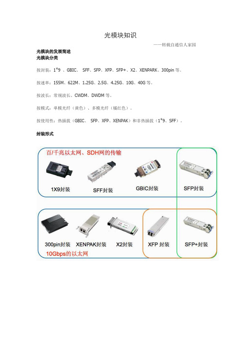
光模块知识——转载自通信人家园光模块的发展简述光模块分类按封装:1*9 、GBIC、SFF、SFP、XFP、SFP+、X2、XENPARK、300pin等。
按速率:155M、622M、1.25G、2.5G、4.25G、10G、40G等。
按波长:常规波长、CWDM、DWDM等。
按模式:单模光纤(黄色)、多模光纤(橘红色)。
按使用性:热插拔(GBIC、SFP、XFP、XENPAK)和非热插拔(1*9、SFF)。
封装形式光模块基本原理光收发一体模块(Optical Transceiver)光收发一体模块是光通信的核心器件,完成对光信号的光-电/电-光转换。
由两部分组成:接收部分和发射部分。
接收部分实现光-电变换,发射部分实现电-光变换。
发射部分:输入一定码率的电信号经内部的驱动芯片处理后驱动半导体激光器(LD)或发光二极管(LED)发射出相应速率的调制光信号,其内部带有光功率自动控制电路(APC),使输出的光信号功率保持稳定。
接收部分:一定码率的光信号输入模块后由光探测二极管转换为电信号,经前置放大器后输出相应码率的电信号,输出的信号一般为PECL电平。
同时在输入光功率小于一定值后会输出一个告警信号。
光模块内部结构光模块的主要参数1. 传输速率传输速率指每秒传输比特数,单位Mb/s 或Gb/s。
主要速率:百兆、千兆、2.5G、4.25G 和万兆。
2.传输距离光模块的传输距离分为短距、中距和长距三种。
一般认为2km 及以下的为短距离,10~20km 的为中距离,30km、40km 及以上的为长距离。
■光模块的传输距离受到限制,主要是因为光信号在光纤中传输时会有一定的损耗和色散。
注意:损耗是光在光纤中传输时,由于介质的吸收散射以及泄漏导致的光能量损失,这部分能量随着传输距离的增加以一定的比率耗散。
色散的产生主要是因为不同波长的电磁波在同一介质中传播时速度不等,从而造成光信号的不同波长成分由于传输距离的累积而在不同的时间到达接收端,导致脉冲展宽,进而无法分辨信号值。
千兆光收发器参数
千兆光收发器参数1. 介绍千兆光收发器是一种用于光纤通信的设备,它能够将电信号转换为光信号,并通过光纤传输。
在高速网络通信中,千兆光收发器起到了至关重要的作用。
本文将详细探讨千兆光收发器的参数,包括传输速率、传输距离、工作波长、接口类型等。
2. 传输速率传输速率是衡量千兆光收发器性能的重要指标之一。
千兆光收发器的传输速率通常为1.25 Gbps,即每秒传输12.5亿个比特。
这种高速传输速率使得千兆光收发器成为高性能网络中不可或缺的组件。
3. 传输距离千兆光收发器的传输距离是指信号在光纤中传输的最远距离。
传输距离与光纤的质量和其他因素有关。
一般来说,千兆光收发器的传输距离可达到几十公里。
对于更远距离的传输,可能需要使用光纤放大器或光纤中继设备。
4. 工作波长千兆光收发器的工作波长是指光信号的波长范围。
常见的工作波长有850 nm、1310 nm和1550 nm。
其中,850 nm适用于短距离传输,1310 nm适用于中距离传输,而1550 nm适用于长距离传输。
选择适当的工作波长可以提高传输效果和信号质量。
5. 接口类型千兆光收发器的接口类型包括SC、LC、FC等。
这些接口类型用于连接光收发器和其他设备,如交换机、路由器等。
不同的接口类型适用于不同的设备和应用场景。
选择适合的接口类型可以确保设备之间的兼容性和信号传输的稳定性。
6. 发射功率发射功率是指千兆光收发器发送光信号的功率。
发射功率的大小直接影响信号的传输距离和质量。
一般来说,发射功率越大,传输距离越远,但也会增加功耗和成本。
因此,在选择千兆光收发器时,需要根据实际需求平衡功率和成本之间的关系。
7. 接收灵敏度接收灵敏度是指千兆光收发器接收光信号的灵敏度。
接收灵敏度的大小决定了千兆光收发器的接收能力和信号质量。
一般来说,接收灵敏度越高,接收能力越强,但也会增加成本。
因此,在选择千兆光收发器时,需要根据实际需求平衡灵敏度和成本之间的关系。
8. 工作温度千兆光收发器的工作温度范围是指其能够正常工作的温度范围。
百兆、千兆和万兆光模块你了解多少

百兆/千兆/万兆光模块你了解多少?什么是百兆光模块、千兆光模块和万兆光模块?它们有什么区别?通过字面意思很容易理解,百兆模块与千兆模块和万兆光模块三者最大的不同是传输速率。
百兆与千兆光模块的封装形式都是SFP的,万兆光模块的封装为SFP+和XFP。
百兆模块传输速度为:155Mb/s和622Mb/s;千兆模块传输速度:1.25Gb/s,2.215Gb/s,4.25Gb/s、6.25Gb/s。
而万兆光模块的传输速率是10Gbps。
除了在传输速率上的差异外,它们更具体的差异在哪里呢?什么是百兆光模块?百兆光模块:百兆光模块就是传输速率是100Mbps的光模块,是基于SFP多源协议(MSA)的小型可插拔(SFP)收发器模块,它是一个连接铜线网络支持100BASE-T以太网标准的SFP光模块。
100Base-T是一种以100Mbps速率工作的局域网(LAN)标准,它通常被称为快速以太网标准,并使用UTP(非屏蔽双绞线)铜质线缆。
百兆SFP光模块主要应用于FAST Ethernet快速以太网,与IEEE 802.3z和802.3ab中指定的百兆以太网和100BASE-T以太网标准兼容。
什么是千兆光模块?千兆光模块:千兆光模块就是传输速率是1000Mbps的光模块,它通常用FE来表示,并且千兆光模块一般有千兆SFP光模块和GBIC光模块两种,传输距离可达到80m—160km。
一般来说,我们可以从产品本身的规格细节以及不同公司提供的光模块命名规则来辨别千兆光模块。
什么是万兆光模块?万兆光模块:万兆光模块就是传输速率是10G的光模块,也被称为10G光模块,它的封装形式为SFP+或者XFP。
万兆光模块的标准有IEEE 802.3ae、IEEE 802.3ak以及IEEE 802.3an,我们在选择万兆光模块的时候,可以考虑价格、功耗、占用空间等因素。
如何区分百兆/千兆/万兆光模块?百兆光模块、千兆光模块和万兆光模块的封装分类:百兆与千兆光模块封装都是SFP,其中千兆光模块包括1000Base SFP光模块、BIDI SFP光模块、CWDM SFP光模块、DWDM SFP光模块、SONET/SDH SFP光模块、GBIC光模块这六种。
GBB-7940G中文资料

***********************************************************************************************************************************************************************OPTOWAY TECHNOLOGY INC. No .38, Kuang Fu S. Road, Hu Kou, Hsin Chu Industrial Park, Hsin Chu, Taiwan 303GBB-7940G (RoHS Compliant)1490 nm TX / 1310 nm RX , 5V / 1.25 Gbps Single-Mode WDM Gigabit Interface Converter (GBIC)***********************************************************************************************************************************************************************FEATURESl 1-Fiber SM Gigabit Interface Converter (GBIC) l Compliant with GBIC Specification Rev. 5.5 l Compliant with IEEE-802.3ah 1000BASE-BX l Compliant with Fibre Channel FC-PH-2 for 100-M5-SN-1 and 100-M6-SN-1l Hot Pluggable Module with SC Connector l 1490 nm LD Transmitter l 1310 nm Receiverl Up to 40 km using Single-mode Optic Cable l SCA-2 Host Connector l Single +5 V Power Supply l RoHS Compliantl Differential PECL Inputs and Outputs l TTL RX-LOS Outputl Class 1 Laser International Safety Standard IEC 60825 CompliantAPPLICATIONSl WDM Gigabit Ethernet Linksl SONET/SDH Equipment Interconnect l Fibre Channel LinksDESCRIPTIONThe GBB-7940G series single-mode optical transceivers meet the Gigabit Interface Converter (GBIC) specification Rev. 5.5. It satisfies the optical interface specifications defined in IEEE 802.3ah 1000BASE BX by using 1490 nm transmitter and 1310 nm receiver. The transmitter section uses a multiple quantum well DFB laser and is a class 1 laser compliant according to International Safety Standard IEC 60825. The receiver section uses an integrated 1310 nm detector preamplifier (IDP) mounted in an optical header and a limiting post-amplifier IC. A PECL input / output logic interface is used. TTL RX-LOS output simplifies interface to external circuitry. A 20-pin SCA-2 host connector is used to connect the converter to the host system.LASER SAFETYThis single mode transceiver is a Class 1 laser product. It complies with IEC 60825 and FDA 21 CFR 1040.10 and 1040.11. The transceiver must be operated within the specified temperature and voltage limits. The optical ports of the module shall be terminated with an optical connector or with a dust plug.ORDER INFORMATIONP/No. Bit Rate(Gb/s) Distance (km) TX (nm) RX (nm) Package Temp (o C) TX Power (dBm) RX Sens. (dBm) RoHSCompliant GBB-7940G1.25401490 DFB1310SC GBIC0 to 70 2 to -3-23 YesAbsolute Maximum RatingsParameterSymbol Min Max Units NotesStorage TemperatureTstg -40 85 o C Operating Case Temperature Topr -5 70 o C Power Supply Voltage Vcc -0.5 6 V Input Voltage --- -0.5 Vcc V Relative HumidityRH595%Recommended Operating ConditionsParameterSymbol Min Typ Max Units Power Supply Voltage Vcc 4.75 5 5.25 V Power Supply CurrentI TX + I RX 200 300 mA Operating Case Temperature Topr 0 70 o C Data Rate10001250Mb/s***********************************************************************************************************************************************************************OPTOWAY TECHNOLOGY INC. No .38, Kuang Fu S. Road, Hu Kou, Hsin Chu Industrial Park, Hsin Chu, Taiwan 303Transmitter Specifications (0o C < Topr < 70o C, 4.75V < Vcc < 5.25V)ParameterSymbol Min Typ Max Units Notes OpticalOptical Transmit Power Po -3 --- 2 dBm 1Output Center Wavelength λ 1480 1500 nmOutput Spectrum Width∆λ 1 nm -20 dB width Side Mode Suppression Ratio SMSR 30 dB Extinction Ratio E R 9 dBOptical Rise Time t r 0.26 ns 20% to 80% value Optical Fall Timet f 0.26 ns 20% to 80% value Relative Intensity Noise RIN -120 dB/HzTotal JitterTJ 227 ps 2 Max. Po at TX-Disable Asserted -35 dBmElectricalDifferential Input Voltage V IH - V IL 0.65 2.0 Vp-p Transmit Fault LoadTX-FAULT LOAD 4.7 10 k Ω 3Transmit Fault Output-Low V TX-FAULT -L 0.0 0.5 V Transmit Fault Output-High V TX-FAULT-H Vcc – 0.5Vcc + 0.3 V TX-Disable Input - Low V TX-DISABLE -L 0 0.8 V TX-Disable Input - High V TX-DISABLE-H2.0 Vcc + 0.3 V TX-Disable Assert Time t_off 10 µsTX-Disable Negate Timet-on 1 ms Time to initialize, includes reset of TX-FAULTt-int300 ms TX FAULT from fault to assertiont-fault 100 µsTX-Disable time to start resett-reset10µsNotes: 1. Output power is power coupled into a 9/125 µm single mode fiber.2. Measured with a 27-1 PRBS.3. Pull-up resistor on host Vcc.Receiver Specifications (0o C < Topr < 70o C, 4.75 V < Vcc < 5.25V)ParameterSymbol Min Typ Max Units Notes Optical Sensitivity--- --- --- -23 dBm 4 Maximum Input Power Pin -3 --- dBm 4Signal detect – Hysteresis 1.0 --- dBWavelength of Operation 1260 1360 nm 5 Optical Return Loss ORL 12 dBRX-LOS – Asserted Pa --- --- -23 dBm Transition: low to high RX-LOS – Deasserted Pd -31 --- --- dBm Transition: high to lowElectricalDifferential Output Voltage V OH - V OL 0.37 2.0 Vp-p Data Output Rise Time Tr RX-DAT 0.35 ns Data Output Fall Time Tf RX-DAT 0.35 ns RX-LOS of Light LoadRX-LOS LOAD 4.7 10 k Ω 6 RX-LOS Output Voltage --- Low V RX-LOS-L 0 0.5 V RX-LOS Outpu Voltage --- High V RX-LOS-H 2.4 Vcc V RX-LOS Assert Time (off to on) T A,RX-LOS 100 µs RX-LOS Deassert Time (on to off)T D,RX-LOS100µsNotes: 4. Minimum sensitivity and saturation levels at BER=1E-12 for a 27-1 PRBS. 5. At least 30 dB optical isolation for the wavelength 1480 to 1500 nm.6. Pull-up resistor on host Vcc.***********************************************************************************************************************************************************************OPTOWAY TECHNOLOGY INC. No .38, Kuang Fu S. Road, Hu Kou, Hsin Chu Industrial Park, Hsin Chu, Taiwan 303A sequence value of 1 indicates that the signal is in the first group to engage during plugging of a module. A sequence value of 2 indicates that the signal is the second and last group. The two guide pins on the connector are electrically connected to the transceiver circuit ground. These two guide pins make contact with circuit prior to sequence 1 signals.Module Definition Module DefinitionMOD-DEF(0) PIN 4MOD-DEF (1) PIN 5MOD-DEF (2) PIN 6Interpretation byHost4TTL LowSCLSDASerial module definitionprotocolModule Definition 4 specifies a serial definition protocol. For this definition, upon power up, MOD-DEF(1:2) appear as no connector (NC) and MOD-DEF(0) is TTL LOW. When the host system detects this condition, it activates the serial protocol. The protocol uses the 2-wire serial CMOS E 2PROM protocol of the ATMEL AT24C01A/02/04 family of components.Units in mmNote: Specifications subject to change without notice.*********************************************************************************************************************************************************************** OPTOWAY TECHNOLOGY INC. No.38, Kuang Fu S. Road, Hu Kou, Hsin Chu Industrial Park, Hsin Chu, Taiwan 303。
海康威视传输产品系列说明书

OPTICAL MODULENETWORK CABLESRECOMMENDED OPTIONSWIRELESS BRIDGEAGGREGATION & CORE ETHERNET SWITCHINDUSTRIAL POE ETHERNET SWITCH≤ 100-ch IPCTypeModel Aggregation switchDS-3E0524TFAccess switch DS-3E01(3)xxP-E(B)Access switchDS-3E01(3)xxP-E/M(B)Access switch DS-3E05xxP-E Access switch DS-3E05xx-EOptical moduleHK-SFP-1.25G-1310-DF-MM100-ch < IPC ≤ 300-chTypeModel Aggregation switch DS-3E2528Access switch DS-3E13xxP-E Access switch DS-3E01(3)xxP-E(B)Access switch DS-3E05xxP-E Access switch DS-3E05xx-E Optical moduleHK-SFP-1.25G-20-1310HK-SFP-1.25G-20-1550300-ch < IPC ≤ 500-chType Model Core switch DS-3E3756TF Core switch DS-3E3740Aggregation switchDS-3E2528Access switch DS-3E23xxP-E Access switch DS-3E05xxP-E Access switch DS-3E01(3)xxP-E(B)Optical moduleHK-SFP-1.25G-20-1310HK-SFP-1.25G-20-1550ModelImageDescriptionHK-SFP-1.25G-20-1310TX 1310 nm/1.25G, RX 1550 nm/1.25G, LC, single mode and single fiber, 20 km, 0~70°C, SFPHK-SFP-1.25G-20-1550TX 1550 nm/1.25G, RX 1310 nm/1.25G, LC, single mode and single fiber, 20 km, 0~70°C, SFPHK-SFP-1.25G-1310-DF-MMTX 1310 nm/1.25G, RX 1310 nm/1.25G, LC, Multi mode and duplex fiber, 1 km, 0~70°C, SFPHK-SFP-1.25G-20-1310-DF TX 1310 nm/1.25G, RX 1310 nm/1.25G, LC, Single mode and duplex fiber, 20 km, 0~70°C, SFPHK-SFP+-10G-20-1270TX 1270 nm/10G, RX 1330 nm/10G, LC, single mode and single fiber, 20 km, 0~70°C, SFP+HK-SFP+-10G-20-1330TX 1330 nm/10G, RX 1270 nm/10G, LC, single mode and single fiber, 20 km, 0~70°C, SFP+Outdoor wireless bridgeElevator wireless bridgeModelDS-3WF01C-2N/ODS-3WF02C-5N/ODS-3WF03CDS-3WF0AC-2NTDS-3WF01C-2NDescriptionSupports point-to-point &point-to-multipoint;Range up to 3 km; 802.11 b/g/n, Built-in 12 dBiantenna up to 150 Mbps; Output power 27 dBm; Angle Horizontal: 60° Vertical: 30°; IP65;Supports point-to-point & point-to-multipoint; Range up to 5 km; 802.11 a/n, Built-in 10 dBi 2×2 MIMO antenna up to 300 Mbps; Output power 24 dBm; Angle Horizontal: 60° Vertical: 16°; IP65;Supports point-to-point & point-to-multipoint; Range up to 15 km; 802.11a/n, Built-in 15dBi 2×2 MIMO antenna with 300 Mbps; Output power 27 dBm; Angle Horizontal: 40° Vertical: 15°; IP65;Supports point-to-point, distance 100 m; IEEE 802.11b/g/n, Built-in 8dBi antenna; Output power 20 dBm; Angle Horizontal: 60° Vertical: 30°; Working temperature: -30 ~65°C; Plug and play, no initial setting;Supports point-to-point, distance 500 m; IEEE 802.11b/g/n, Built-in 6dBi antenna; Output power 27 dBm; Angle Horizontal: 65° Vertical: 60°; Working temperature: -30 ~65°C;Plug and play, no initial setting;ModelDS-1LN5E-SDS-1LN6-UUDS-1LN5E-E/EDS-1LN6-UE-WDescriptionUTP CAT 5E, 305 meters Core diameter: 0.5 mm Solid copper,CM,grayUTP CAT 6, 305 meters Core diameter: 0.565 mm Solid copper, CM, orangeUTP CAT 5E, 305 meters Core diameter: 0.45 mm Solid copper, CMX,grayUTP CAT 6, 305 meters, Core diameter: 0.53 mm Solid copper, CM,whiteModelDS-3E0524TFDS-3E2528DS-3E3740DS-3E3756TFManagement Unmanaged Full-managed Full-managed Full-managed Ports12 × Gigabit RJ45 ports 12 × Gigabit SFP ports24 × Gigabit RJ45 ports 4 × Gigabit SFP ports32 × Gigabit RJ45 ports 8 × 10G SFP+ ports24 × Gigabit RJ45 ports 24 × Gigabit SFP ports 8 × 10G SFP+ portsPacket Forwarding Rate 35.7 Mpps 42 Mpps 136 Mpps 136 Mpps Switching Capacity 48 Gbps 56 Gbps 224 Gbps 256 GbpsMAC Address Table 16 K 8 K64 K64 KManagement Mode -Console, Telnet, SSH2.0, Web, SNMP v1/v2/v3, TFTP, RMONOther Software Features-STP, VLAN, Mirroring, IGMP Snoopingand IGMP v1/v2, L2/L3/L4 ACL, LACP,EAPS, ERPSSTP, VLAN, Mirroring, IGMP Snooping and IGMP v1/v2, L2/L3/L4 ACL, LACP, EAPS,Operating Temperature -5°C~50°C0°C~45°C0°C~45°C0°C~45°C Dimension (440 × 186.5 × 44.5) mm (440 × 230 × 45) mm (442.5 × 315 × 44) mm (442.5 × 350 × 44) mmPower SupplyModelELG-150-48AImageOutput Voltage 48 VRated Current 3.13 ARated Power 150 WOperating Temperature-40~90°CIP Rating IP65AccessoryOptional accessory for industrial PoEswitchIndustrial switchModelDS-3T0306PDS-3T0310PManagement UnmanagedUnmanagedPorts 4 × 10/100 Mbps PoE RJ45 ports2 × Gigabit uplink SFP ports 8 × 10/100 Mbps PoE RJ45 ports 2 × Gigabit uplink SFP ports PoE Standards IEEE 802.3af, IEEE802.3atIEEE 802.3af, IEEE802.3atPoE Budget≤ 120 W ≤ 240 W Packet Forwarding Rate 3.6 Mpps 4.2 Mpps Switching Capacity 8.8 Gbps 8.8 Gbps MAC Address Table 4 K 4 K Surge Protection 2 KV 2 KV Operating Temperature -40°C~75°C -40°C~75°C Dimension(155 × 130 × 42) mm(170 × 156 × 42) mmUNMANAGED NON-POE ETHERNET SWITCHUNMANAGED POE ETHERNET SWITCHMANAGED POE ETHERNET SWITCHUNMANAGED SWITCHIEEE 802.3bt Standard Hi-PoE, Max. 90 W for One PortIEEE 802.3bt standard Hi-PoE port provides max. 90 W power supply for high power devices such as domes.Up to 300 m Long Range PoE TransmissionBased on all series of camera tests with Hikvisionnetwork cables, up to 300 m long range PoE transmission is provided.Intelligent PoE ManagementWhen the power supply exceeds the limit, PoE ports intelligently manage the power supply, which extends the switch lifetime.4/8-Core Adaptive Power Supply with Less Power Loss8-core power supply reduces the power loss on cables.6KV Surge Protection to Improve Reliability in Harsh EnvironmentThe built-in surge protection device protects the switch from the sudden lightning surge in harsh environment.Design for Video TransmissionVIP port ensures important data transmission when network congestion occurs.Hi-PoE SwitchesModelDS-3E0106HP-EDS-3E0310HP-EPorts1 × 10/100 Mbps Hi-PoE port 3 × 10/100 Mbps PoE ports2 × 10/100 Mbps RJ45 ports 1 × 10/100 Mbps Hi-PoE port 7 × 10/100 Mbps PoE ports 2 × Gigabit RJ45 ports PoE Standards Port 1: IEEE 802.3af, IEEE 802.3at, IEEE802.3btPorts 2 to 4: IEEE 802.3af, IEEE 802.3atPort 1: IEEE 802.3af, IEEE 802.3at, IEEE802.3btPorts 2 to 8: IEEE 802.3af, IEEE 802.3atPoE Budget 60 W 110 W Max. port PoE power Port 1: 60 W Ports 2 to 4: 30 W Port 1: 90 W Ports 2 to 8: 30 W PoE Extend Mode Max. 300 m, Port 1-4Max. 300 m, Port 1-8Packet Forwarding Rate 0.893 Mpps 4.166 Mpps Switching Capacity 1.2 Gbps 5.6 Gbps MAC Address Table 2 K 16 K Surge Protection 6 KV 6 KV Operating Temperature-10°C~55°C -10°C~55°CDimension(145 × 25.6 × 68.45) mm(217.6 × 27.8 × 103.35) mm10/100 Mbps SwitchesModelDS-3E0105P-E/M(B)DS-3E0109P-E/M(B)DS-3E0318P-E/M(B)DS-3E0326P-E/M(B)DS-3E0105P-E(B)DS-3E0109P-E(C)DS-3E0318P-E(B)DS-3E0326P-E(B)Ports4 × 10/100 Mbps PoE RJ45 ports 1 × 10/100 Mbps uplink RJ45 port8 × 10/100 Mbps PoE RJ45 ports 1 × 10/100 Mbps uplink RJ45 port16 × 10/100 Mbps PoE RJ45 ports 1 × Gigabit uplink RJ45 port 1 × Gigabit uplink SFP port 24 × 10/100 Mbps PoE RJ45 ports1 × Gigabit uplink RJ45 port1 × Gigabit uplink SFP port4 × 10/100 Mbps PoE RJ45 ports1 × 10/100 Mbps uplink RJ45 port8 × 10/100 Mbps PoE RJ45 ports1 × 10/100 Mbps uplink RJ45 port16 × 10/100 Mbps PoE RJ45 ports 2 × Gigabit comb ports (2 RJ45 Ports and 2 SFP Ports)24 × 10/100 Mbps PoE RJ45 ports 2 × Gigabit comb ports (2 RJ45Ports and 2 SFP Ports)PoE Standards IEEE 802.3af, IEEE802.3atIEEE 802.3af, IEEE802.3atIEEE 802.3af, IEEE802.3atIEEE 802.3af, IEEE802.3atIEEE 802.3af, IEEE802.3atIEEE 802.3af, IEEE802.3atIEEE 802.3af, IEEE802.3atIEEE 802.3af, IEEE802.3atPoE Budget35 W60 W130 W230 W60 W115 W 230 W370 WPoE Extend Mode Max.300 m, Port 1-4Max. 300 m, Port 1-8Max. 300 m, Port 9-16Max. 300 m, Port 17-24Max 300 m, Port 1-4Max 300 m, Port 1-8Max. 300 m, Port 9-16Max. 300 m, Port 17-24Packet Forwarding Rate0.744 Mpps 1.34 Mpps 5.36 Mpps 6.55 Mpps 0.74 Mpps 1.34 Mpps 5.36 Mpps 6.55 Mpps Switching Capacity1 Gbps 1.8 Gbps 7.2 Gbps 8.8 Gbps 1 Gbps 1.8 Gbps 7.2 Gbps 8.8 Gbps MAC Address Table 1 K 2 K 4 K 4 K 1 K 2 K 4 K 4 K Surge Protection 6 KV 6 KV 6 KV 6 KV 6 KV 6 KV 6 KV 6 KV Operating Temperature-10°C~55°C -10°C~55°C -10°C~55°C -10°C~55°C -10°C~55°C -10°C~55°C -10°C~55°C -10°C~55°C Dimension(105 × 27.6 × 83.1)mm(170 × 27.6 × 93.1) mm(266 × 44.5 × 220.8) mm(335 × 44.5 × 226) mm(105 × 27.6 × 83.1) mm(170 × 27.6 × 93.1) mm(440 × 44 × 220.8) mm(440 × 44 × 220.8) mmGigabit SwitchesModel DS-3E0505P-EDS-3E0510P-EDS-3E0518P-EDS-3E0526P-EPorts4 × Gigabit PoE RJ45 ports1 × Gigabit RJ45 port 8 × Gigabit PoE RJ45 ports 1 × Gigabit RJ45 port 1 × Gigabit SFP port 16 × Gigabit PoE RJ45 ports 1 × Gigabit RJ45 port 1 × Gigabit SFP port 24 × Gigabit PoE RJ45 ports 1 × Gigabit RJ45 port 1 × Gigabit SFP port PoE Standards IEEE 802.3af, IEEE802.3atIEEE 802.3af, IEEE802.3atIEEE 802.3af, IEEE802.3atIEEE 802.3af, IEEE802.3atPoE Budget60 W 110 W 230 W 370 W Packet Forwarding Rate 7.44 Mpps 14.88 Mpps 26.784 Mpps 38.688 Mpps Switching Capacity 10 Gbps 20 Gbps 36 Gbps 52 Gbps MAC Address Table 2 K 4 K 8 K 8 K Surge Protection6 KV 6 KV 6 KV 6 KV Operating Temperature-10°C~55°C -10°C~55°C-10°C~55°C -10°C~55°C Dimension(105 × 27.6 × 83.1) mm(217.6 × 27.8 × 108.55) mm(440 × 44 × 220.8) mm(440 × 44 × 220.8) mmModel DS-3E0105D-EDS-3E0108D-EDS-3E0505D-EDS-3E0508D-EDS-3E0508-EDS-3E0516-EDS-3E0524-EPorts 5 × 10/100 Mbps RJ45 ports 8 × 10/100 Mbps RJ45 ports 5 × Gigabit RJ45 ports 8 × Gigabit RJ45 ports 8 × Gigabit RJ45 ports 16 × Gigabit RJ45 ports 24 × Gigabit RJ45 portsSwitching Capacity 1 Gbps 1.6 Gbps 10 Gbps 16 Gbps 16 Gbps 32 Gbps 48 GbpsPacket Forwarding Rate 0.744 Mpps 1.1904 Mpps 7.44 Mpps 11.904 Mpps 11.9 Mpps 23.8 Mpps 35.7 MppsMAC Address Table 1 K 1 K 2 K 4 K 4 K 8 K 8 KSurge Protection ---- 4 KV 4 KV 4 KVOperating Temperature 0°C~40°C 0°C~40°C 0°C~40°C 0°C~40°C 0°C~40°C 0°C~40°C 0°C~40°CDimension (82 × 52 × 22.4) mm (124 × 59 × 23.2) mm (92.8 × 65.8 × 22.8) mm (142 × 90 × 23) mm (186.7 × 106.7 × 33.3) mm (440 × 178.8 × 44) mm (440 × 178.8 × 44) mmModel DS-3E1310P-EDS-3E1318P-EDS-3E1326P-EDS-3E2310PDS-3E2318PDS-3E2326PDS-3E2510PDS-3E2528PManagement Web-managed Web-managed Web-managed Full-managed Full-managed Full-managed Full-managed Full-managed Ports 8 × 10/100 Mbps PoE RJ45 ports 2 × Gigabit comb ports (2 RJ45 Ports and 2 SFP Ports)16 × 10/100 Mbps PoE RJ45 ports 2 × Gigabit comb ports (2 RJ45 Ports and 2 SFP Ports)24 × 10/100 Mbps PoE RJ45 ports 2 × Gigabit comb ports (2 RJ45 Ports and 2 SFP Ports)8 × 10/100 Mbps PoE RJ45 ports 2 × Gigabit comb ports (2 RJ45 Ports and 2 SFP Ports)16 × 10/100 Mbps PoE RJ45 ports 2 × Gigabit comb ports (2 RJ45 Ports and 2 SFP Ports)24 × 10/100 Mbps PoE RJ45 ports 2 × Gigabit comb ports (2 RJ45Ports and 2 SFP Ports)8 × Gigabit PoE RJ45 ports 2 × Gigabit SFP ports 24 × Gigabit PoE RJ45 ports 4 × Gigabit SFP ports PoE Standards IEEE 802.3af, IEEE802.3atIEEE 802.3af, IEEE802.3atIEEE 802.3af, IEEE802.3atIEEE 802.3af, IEEE802.3atIEEE 802.3af, IEEE802.3atIEEE 802.3af, IEEE802.3atIEEE 802.3af, IEEE802.3atIEEE 802.3af, IEEE802.3atPoE Budget 123 W 230 W370 W125 W 300 W 380 W 125 W 380 W PoE Extend Mode Max. 250 m, Port 1-8Max. 250 m, Port 1-16Max. 250 m, Port 1-24-----Packet Forwarding Rate 1.34 Mpps 5.36 Mpps 6.55 Mpps 5.6 Mpps 8.4 Mpps 9.6 Mpps 15 Mpps 42 Mpps Switching Capacity5.4 Gbps 7.2 Gbps 8.8 Gbps 10 Gbps 21.2 Gbps 22.8 Gbps 20 Gbps 56 Gbps MAC Address Table 4 K4 K4 K8 K8 K8 K8 K8 KManagement Mode SNMP v1/v2, WEB managementConsole, Telnet, SSH2.0, Web, SNMP v1/v2/v3, TFTP, RMONOther Software Features STP, VLAN, Mirroring, IGMP Snooping and IGMP v1/v2STP, VLAN, Mirroring, IGMP Snooping and IGMP v1/v2, L2/L3/L4 ACL, LACP, EAPS, ERPSSurge Protection 4 KV 4 KV 4 KV 4 KV 4 KV 4 KV 4 KV 4 KV Operating Temperature 0°C~40°C 0°C~40°C 0°C~40°C 0°C~40°C 0°C~40°C 0°C~40°C 0°C~45°C 0°C~45°C Dimension(294 × 165.8 × 44) mm(440 × 285 × 43) mm(440 × 285 × 43) mm(280 × 179 × 45) mm(440 × 232 × 44) mm(440 × 232 × 44) mm(280 × 179 × 45) mm(440 × 232 × 45) mm。
华为光模块参数
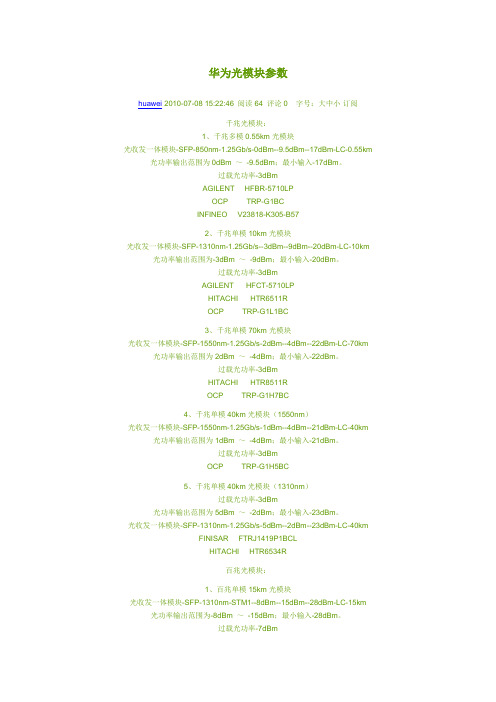
华为光模块参数huawei 2010-07-08 15:22:46 阅读64 评论0 字号:大中小订阅千兆光模块:1、千兆多模0.55km光模块光收发一体模块-SFP-850nm-1.25Gb/s-0dBm--9.5dBm--17dBm-LC-0.55km 光功率输出范围为0dBm ~-9.5dBm;最小输入-17dBm。
过载光功率-3dBmAGILENT HFBR-5710LPOCP TRP-G1BCINFINEO V23818-K305-B572、千兆单模10km光模块光收发一体模块-SFP-1310nm-1.25Gb/s--3dBm--9dBm--20dBm-LC-10km 光功率输出范围为-3dBm ~-9dBm;最小输入-20dBm。
过载光功率-3dBmAGILENT HFCT-5710LPHITACHI HTR6511ROCP TRP-G1L1BC3、千兆单模70km光模块光收发一体模块-SFP-1550nm-1.25Gb/s-2dBm--4dBm--22dBm-LC-70km 光功率输出范围为2dBm ~-4dBm;最小输入-22dBm。
过载光功率-3dBmHITACHI HTR8511ROCP TRP-G1H7BC4、千兆单模40km光模块(1550nm)光收发一体模块-SFP-1550nm-1.25Gb/s-1dBm--4dBm--21dBm-LC-40km 光功率输出范围为1dBm ~-4dBm;最小输入-21dBm。
过载光功率-3dBmOCP TRP-G1H5BC5、千兆单模40km光模块(1310nm)过载光功率-3dBm光功率输出范围为5dBm ~-2dBm;最小输入-23dBm。
光收发一体模块-SFP-1310nm-1.25Gb/s-5dBm--2dBm--23dBm-LC-40kmFINISAR FTRJ1419P1BCLHITACHI HTR6534R百兆光模块:1、百兆单模15km光模块光收发一体模块-SFP-1310nm-STM1--8dBm--15dBm--28dBm-LC-15km 光功率输出范围为-8dBm ~-15dBm;最小输入-28dBm。
1.25GSFP光模块介绍

1.25GSFP光模块介绍1.25G SFP transceiver module with DDM functionRTXM191 DDM RoHS SeriesFeaturesUp to 1.25Gbps data rateDuplex LC receptacle optical interface compliant Single +3.3V power supply DDM function implemented External calibration Hot-pluggableReceiver Loss of Signal Output AC coupling of PECL signals Serial ID module on MOD(0-2)International Class 1 laser safety certified Transmitter disable inputOperating temperature range: -10 O C ~+70 O C CWDM module Operating temperature range: 0 O C ~+70 O C Compliant with RoHS&WEEERTXM191 DDM RoHS SeriesApplicationsGigabit EthernetGigabit Fiber Channel Switch to switch interfaceSwitched backplane applicationsStandardsCompliant with SFP MSA (INF-8074i) Compliant with SFF-8472 v9.3Compliant with IEEE802.3z Gigabit Ethernet Compliant with ITU-T G .695 Compliant with FC-PI v2.0 Compliant with RoHS&WEEEAbsolute Maximum RatingsParameterSymbol UnitMin MaxStorage Temperature Range T so C -40 +85 Relative Humidity RH % 5 95 Power Supply V oltage V cc V-0.5 +4Recommended Operating ConditionsSpecifications(tested under recommended operating conditions ,unless otherwise noted)Optical DessertS -35 15km ~80km PIN LOS Optical AssertdB -45120km APD LOS HysteresisdB0.5 3 5 7Note1. The supply current includes SFP module’s supply current and test board working current.Note2. The CWDM transmitter center wavelengths “λ”are: 1471, 1491, 1511, 1531, 1551, 1571, 1591, 1611nm Note3. TP refers to the compliance point specified in IEEE802.3z, section 38.2.1.Note4. RIN is the laser noise, integrated over a specified bandwidth, measured relative to average optical power with 12dB return loss. For multimode application, the RIN is better than -117dB/Hz.Note5. Optical transition time is the time interval required for the rising or falling edge of an optical pulse to transition between the 20% and 80% amplitudes relative to the logical 1 and 0 levelsNote6. Measured with a PRBS 223-1 test pattern, @1.25Gb/s, EX=10dB, BER<10-12.Note7. The LOS Hysteresis to minimize “chatter” on the output line. In principle, Hysteresis alone does not guarantee chatter-free operationDigital Diagnostic Memory Map2 wire address 1010000X (A0) 2 wire address 1010001X (A2)9509555119255127EEPROM Serial ID Memory ContentsAccessing Serial ID Memory uses the 2 wire address 1010000X (A0). Memory Contents of Serial ID are shown in Table 2. Table 2 Serial ID Memory ContentsData AddressSize(Bytes)Name of Field Contents(Hex) DescriptionBASE ID FIELDS0 1Identifier 03 SFP1 1 Ext. Identifier 04 SFP function is defined by serial IDonly2 1Connector 07 LCConnector3-10 8 Transceiver TransceiverCodes11 1Encoding 03 NRZ12 1BR,Nominal 0C 1.25Gbit/s13 1Reserved 0014 1Length(9µm) km15 1Length(9µm) 100m16 1Length(50µm) 10m17 1Length(62.5µm)10mTransceiver transmit distance18 1 Length (Copper) 00 Not compliant19 1Reserved 0020-35 16 Vendor name 57 54 44 20 20 20 20 2020 20 20 20 20 20 20 20“WTD”(ASCII)36 1Reserved 0037-39 3 Vendor OUI 00 00 0040-55 16 Vendor PN Transceiver part number56-59 4 Vendor rev 20 20 20 2060-61 2 Wavelength Transceiverwavelength62 1Reserved 0063 1 CC_BASE Check Sum (Variable) Check code for Base ID Fields EXTENDED ID FIELDS64-65 2 Options 00 1A TX_DISABLE, TX_FAULT andLoss of Signal implemented.66 1BR,max 0067 1BR,min 0068-83 16 Vendor SN 42 30 30 39 38 32 32 2020 20 20 20 20 20 20 20Serial Number of transceiver (ASCII). For example “B009822”. 84-91 8 Date code 30 32 31 30 30 35 20 20Manufactory date code. Forexample “021005”.92 1Diagnostic 58 DigitaldiagnosticmonitoringMonitoring Type implemented, “externallycalibrated” is implemented, RXmeasurement type is “AveragePower”.93 1 Enhanced Options B0 Optional Alarm/Warning flagsimplemented for all monitoredquantities, Optional SoftTX_FAULT monitoringimplemented, Optional SoftRX_LOS monitoring implemented.94 1SFF_8472Compliance 01 Includes functionality described inRev9.3 SFF-8472.95 1 CC_EXT Check Sum (Variable) Check sum for Extended ID Field. VENDOR SPECIFIC ID FIELDS96-127 32 Vendor Specific Read only Depends on customer information 128-255 128 Reserved Read only Filled by zero Diagnostic Monitor FunctionsDiagnostic Monitor Functions interface uses the 2 wire address 1010001X (A2). Memory contents of Diagnostic Monitor Functions are shown in Table 3Table 3 Memory contents of Diagnostic Monitor FunctionData Address Field Size(bytes)Name Contents and DescriptionAlarm and Warning Thresholds00-01 2 Temperature High Alarm Set to 85 O C02-03 2 Temperature Low Alarm Set to -5 O C04-05 2 Temperature High Warning Set to 75 O C06-07 2 Temperature Low Warning Set to 0 O C08-09 2 Vcc High Alarm Set to 3.6 V10-11 2 Vcc Low Alarm Set to 3.0 V12-13 2 Vcc High Warning Set to 3.5 V14-15 2 Vcc Low Warning Set to 3.1 V16-17 2 BiasHighAlarm 2×IBias(25 o C)+2018-19 2 BiasLowAlarm 25%×IBias(25 o C)20-21 2 BiasHighWarning 2×IBias(25 o C )+1022-23 2 BiasLowWarning 50%×IBias(25 o C)24-25 2 TX Power High Alarm Manufacture measurement plus 2dB 26-27 2 TX Power Low Alarm Manufacture measurement minus 2dB 28-29 2 TX Power High Warning Manufacture measurement plus 1dB 30-31 2 TX Power Low Warning Manufacture measurement minus 1dB32-33 2 RX Power High Alarm Maximum input optical power34-35 2 RX Power Low Alarm Minimum input optical power36-37 2 RX Power High Warning Maximum input power minus 3dB 38-39 2 RX Power Low Warning Manufacture measurement plus 3dB 40-55 16 ReservedCalibration Constants56-59 4 RX Power Calibration Data4 60-63 4 RX Power Calibration Data3 Single precision floating-point numbers (various values at each device)64-67 4 RX Power Calibration Data2 68-71 4 RX Power Calibration Data1 72-75 4 RX Power Calibration Data0 Single precision floating-point numbers (various values at each device)76-77 2 Bias Calibration Data1 00 01 (fixed)78-79 2 Bias Calibration Data0 00 00 (fixed)80-81 2 TX Power Calibration Data100 01 (fixed)82-83 2 TX Power Calibration Data0 00 00 (fixed)84-85 2 Temperature Calibration Data100 01 (fixed)86-87 2 Temperature Calibration Data000 00 (fixed)88-89 2 Vcc Calibration Data1 00 01 (fixed)90-91 2 Vcc Calibration Data0 00 00 (fixed)92-94 3 Reserved 00 00 00 (fixed)95 1 Check Sum Checksum of bytes 0-94Real Time Diagnostic Monitor Interface96-97 2 Measured Temperature Yield a 16-bit A/D value (see Table 3.1)98-99 2 Measured Vcc Yield a 16-bit A/D value (see Table 3.1)100-101 2 Measured Bias Yield a 16-bit A/D value (see Table 3.1)102-103 2 Measured TX Power Yield a 16-bit A/D value (see Table 3.1)104-105 2 Measured RX Power Yield a 16-bit A/D value (see Table 3.1)106-109 4 Reserved110 1 Logic Status See Table 3.2111 1 AD Conversion Updates See Table 3.2112-119 8 Alarm and Warning Flags See Table 3.3Vendor Specific120-127 8 VendorSpecific Don’tAccess128-247 120 UserwritableEEPROM248-255 8 VendorSpecific Don’tAccessThe measured values located at bytes 96-105(in the 2 wire address 0xA2) are raw A/D values (16-bit integers) of transceiver temperature, supply voltage, laser bias current, laser optical output power and received power. All the measured values are “Externally Calibrated”, and then it is necessary to convert raw A/D values to real world units by the manner as shown in Table 3.1.Table 3.1 Real Time Diagnostic Monitor ValuesByteNameDescription96 Temperature MSB 97 Temperature LSB Internally measured transceiver temperature. Compliant with External Calibration of SFF-8472. 98 Vcc MSB 99 Vcc LSB Internally measured supply voltage. Compliant with External Calibration of SFF-8472.100 Laser Bias MSB 101 Laser Bias LSB Measured Laser bias current. Compliant with External Calibration of SFF-8472. 102 Tx Power MSB 103Tx Power LSBMeasured Tx power. Compliant with External Calibration of SFF-8472.104 Rx Power MSB105 Rx Power LSB Measured Tx power. Compliant with External Calibration of SFF-8472.This transceiver implements two optional status bytes, “Logic States” at byte 110(0xA2)” and “A/D Updated” at byte111(0xA2) as shown in Table 3.2. “A/D Updated” status bits allow the user to verify if an update from the analog-digital conversion has occurred of the measured values, temperature, Vcc, laser bias, Tx power and Rx power. The user writes the byte to 0x00. Once a conversion is completed for a given value, its bit will change to ‘1’Table 3.2 Logic Status and AD Conversion Updates Byte Bit NameDescription110 7 Tx Disable State Optional digital State of the Tx Disable input pin. 110 6 Soft Tx Disable Control Not supported (set to 0). 110 5 ReservedSet to 0.110 4 Rx Rate Select State Not supported (set to 1). 110 3 Soft Rate Select Control Not supported (set to 0).110 2 Tx Fault Optional digital state of the Tx Fault output pin. 110 1 LOSOptional digital state of the LOS output pin. 110 0 Power on Logic Bit will be 0 when the analog monitoring is active. 111 7 Temp A/D Valid Indicates A/D value in Bytes 96/97 is valid. 111 6 Vcc A/D Valid Indicates A/D value in Bytes 98/99 is valid. 111 5 Laser Bias A/D Valid Indicates A/D value in Bytes 100/101 is valid. 111 4 Tx Power A/D Valid Indicates A/D value in Bytes 102/103 is valid. 111 3 Rx Power A/D Valid Indicates A/D value in Bytes 104/105 is valid. 111 2 Reserved Set to 0. 111 1 Reserved Set to 0. 111ReservedSet to 0.Each of the measured values has a corresponding high alarm, low alarm, high warning and low warning threshold level at location 00-39(x0A2) written as the data format of a corresponding valued shown in Table 3.3.Alarm and warning flags at bytes 112-119(0xA2) are defined as follows.(1) Alarm flags indicate conditions likely to result (or have resulted) in link failure and cause forimmediate action.(2)Warning flags indicate conditions outside the guaranteed operating specification of transceiver but notnecessarily causes of immediate link failures.Table 3.3 Alarm and Warning FlagsByte Bit(s) Name Description112 7 Temperature High Alarm Set when temperature monitor value exceeds high alarmlevel.112 6 Temperature Low Alarm Set when temperature monitor value exceeds low alarmlevel.112 5 Vcc High Alarm Set when Vcc monitor value exceeds high alarm level.112 4 Vcc Low Alarm Set when Vcc monitor value exceeds Low alarm level.112 3 Laser Bias High Alarm Set when laser bias monitor value exceeds high alarm level. 112 2 Laser Bias Low Alarm Set when laser bias monitor value exceeds low alarm level. 112 1 Tx Power High Alarm Set when Tx power monitor value exceeds high alarm level 112 0 Tx Power Low Alarm Set when Tx power monitor value exceeds low alarm level. 113 7 Rx Power High Alarm Set when Rx power monitor value exceeds high alarm level 113 6 Rx Power Low Alarm Set when Rx power monitor value exceeds low alarm level 113 5-0 Reserved All bits set to 0.114 7-0 Reserved All bits set to 0.115 7-0 Reserved All bits set to 0.116 7 Temperature High warning Set when temperature monitor value exceeds high warninglevel.116 6 Temperature Low warning Set when temperature monitor value exceeds low warninglevel.116 5 Vcc High warning Set when Vcc monitor value exceeds high warning level.116 4 Vcc Low warning Set when Vcc monitor value exceeds Low warning level.116 3 Laser Bias High warning Set when laser bias monitor value exceeds high warninglevel.116 2 Laser Bias Low warning Set when laser bias monitor value exceeds low warning level. 116 1 Tx Power High warning Set when Tx power monitor value exceeds high warninglevel116 0 Tx Power Low warning Set when Tx power monitor value exceeds low warninglevel.117 7 Rx Power High warning Set when Rx power monitor value exceeds high warninglevel117 6 Rx Power Low warning Set when Rx power monitor value exceeds low warning level 117 5-0 Reserved All bits set to 0.118 7-0 Reserved All bits set to 0.119 7-0 Reserved All bits set to 0.Pin DescriptionAs Viewed Through Top of BoardPin Name Function/Description Engagement order NotesGround 11 VeeT Transmitter2 TX Fault Transmitter Fault Indication3 13 TX Disable Transmitter Disable-Module disables on high or open 3 24 MOD-DEF2 Module Definition 2-Two wire serial ID interface 3 35 MOD-DEF1 Module Definition 1-Two wire serial ID interface 3 36 MOD-DEF0 Module Definition 0-Two wire serial ID interface 3 37 Rate Select Not Connected 38 LOS Loss of Signal 3 4Ground 19 VeeR ReceiverGround 110 VeeR ReceiverGround 111 Veer Receiver12 RD- Inverse Received Data out 3 513 RD+ Received Data out 3 5Ground 114 VeeR Receiver15 VccR Receiver Power —— +3.3V±5% 2 616 VccT Transmitter Power —— +3.3 V±5% 2 6Ground 117 VeeT Transmitter18 TD+ Transmitter Data In 3 719 TD- Inverse Transmitter Data In 3 7Ground 120 VeeT TransmitterNote1.TX Fault is open collector/drain output which should be pulled up externally with a 4.7K – 10KΩresistor on the host board to supplynormal operation. In the low state, the output will be pulled to <0.8V.Note2. TX Disable input is used to shut down the laser output per the state table below. It is pulled up within the module with a 4.7 – 10K resistor.Low (0 – 0.8V): Transmitter onBetween (0.8V and 2V): UndefinedHigh (2.0 – VccT): Transmitter DisabledOpen : Transmitter DisabledNote3.Mod-Def 0, 1, 2. These are the module definition pins. They should be pulled up with a 4.7 - 10K resistor on the host board to supply less than VccT+0.3V or VccR+0.3V.Mod-Def 0 is grounded by the module to indicate that the module is present.Mod-Def 1 is clock line of two wire serial interface for optional serial ID.Mod-Def 2 is data line of two wire serial interface for optional serial ID.Note4. LOS (Loss of signal) is an open collector/drain output which should be pulled up externally with a 4.7 – 10K resistor on the host board to supplyNote5.RD-/+: These are the differential receiver outputs. They are AC coupled 100Ωdifferential lines which should be terminated with 100Ωdifferential at the user SERDES. The AC coupling is done inside the module and thus not required on the host board.Note6. VccR and VccT are the receiver and transmitter power supplies. They are defined as 3.3V±5% at the SFP connector pin. The in-rush current will typically be no more than 30mA above steady state supply current after 500ns.Note7. TD-/+: These are the differential transmitter inputs. They are AC coupled differential lines with 100Ω differential termination inside the module. The AC coupling is done inside the module and is thus not required on host board.Block diagramRequired Host Board ComponentsThe MSA power supply noise rejection filter is required on the host PCB to meet data sheet performance. The MSA filter incorporates an inductor which should be rated 400mADC and 1Ωserial resistance or better. It should not be replaced with a ferrite. The required filter is illustrated in Figure 3. The MSA also specifies that 4.7K to 10KΩpull-up resistors for TX_FAULT, LOS, and MOD_DEF0,1,2 are required on the host PCB. Figure is the suggested transceiver/host interface.Package outlinePCB layout recommendationRegulatory ComplianceFeature Test Method PerformanceRoHS BS EN 1122: 2001US EPA METHOD3050BUS EPA METHOD3052US EPA METHOD3060A Pb <1000ppm Cr6+ <1000ppm Hg <1000ppm PBB <1000ppm PBDE <1000ppm Cd <100ppm Electrostatic Discharge (ESD) to the Electrical Pins MIL-STD-883EMethod 3015.7Class 1 (>1.5kV) – Human Body ModelElectrostatic Discharge(ESD) ImmunityIEC61000-4-2 Class 2(>4.0kV)Electromagnetic Interference (EMI) CISPR22 ITE Class BFCC Class BCENELEC EN55022VCCI Class 1Compliant with standardImmunity IEC61000-4-3Class2Typically show no measurable effect from a 3V/m field swept from 80 to 1000MHz applied tothe transceiver without a chassis enclosure.FDA 0322110-00CDRH 21-CFR 1040 Class 1UL E239070TUV-GS B0501 54481 001SafetyCE E8 0501 54481 004Ordering InformationSpecificationPart NoPackage Data rate Laser Power Detector Sensitivity Temp Reach Other ApplicationCodeRTXM191-550 SFP 1.25G 850nm VCSEL -9.5 ~ -3dBm PIN -18dBm (max)-10~70o C550m DDM, RoHS1000Base-SX RTXM191-400 SFP 1.25G 1310nm FP -9 ~ -3dBm PIN -20dBm (max)-10~70o C15km DDM, RoHS1000Base-LX RTXM191-402 SFP 1.25G 1310nm FP -5 ~ 0dBm PIN -23dBm (max)-10~70o C30km DDM, RoHS1000Base-LH RTXM191-450 SFP 1.25G 1310nm DFB -2 ~ +3dBm PIN -23dBm (max)-10~70o C40km DDM, RoHS1000Base-LH1 RTXM191-500 SFP 1.25G 1550nm DFB -4 ~ +1dBm PIN -20dBm (max)-10~70o C40km DDM, RoHS1000Base-LH2 RTXM191-502 SFP 1.25G1550nm DFB -2 ~ +3dBm PIN -23dBm (max)-10~70o C80km DDM, RoHS1000Base-ZX RTXM191-504 SFP 1.25G 1550nm DFB 0 ~ +3dBm APD-31dBm (max)-10~70o C120km DDM, RoHS1000Base-EX RTXM191-647 SFP 1.25G 1471nm CWDM 0 ~ +3dBm PIN -24dBm (max)0~70o C80km DDM, RoHS CWDM RTXM191-649 SFP 1.25G 1491nm CWDM 0 ~ +3dBm PIN -24dBm (max)0~70o C80km DDM, RoHS CWDM RTXM191-651 SFP 1.25G 1511nm CWDM 0 ~ +3dBm PIN -24dBm (max)0~70o C80km DDM, RoHS CWDM RTXM191-653 SFP 1.25G 1531nm CWDM 0 ~ +3dBm PIN -24dBm (max)0~70oC80km DDM, RoHS CWDM RTXM191-655 SFP 1.25G 1551nm CWDM 0 ~ +3dBm PIN -24dBm (max)0~70o C80km DDM, RoHS CWDM RTXM191-657 SFP 1.25G 1571nm CWDM 0 ~ +3dBm PIN -24dBm (max)0~70o C80km DDM, RoHS CWDM RTXM191-659 SFP 1.25G 1591nm CWDM 0 ~ +3dBm PIN -24dBm (max)0~70o C80km DDM, RoHS CWDM RTXM191-661 SFP 1.25G 1611nm CWDM 0 ~ +3dBm PIN -24dBm (max)0~70o C80km DDM, RoHS CWDM RTXM191-847 SFP 1.25G 1471nm CWDM 0 ~ +3dBm APD-32dBm (max)0~70o C120km DDM, RoHS CWDM RTXM191-849 SFP 1.25G 1491nm CWDM 0 ~ +3dBm APD-32dBm (max)0~70o C120km DDM, RoHS CWDM RTXM191-851 SFP 1.25G 1511nm CWDM 0~ +3dBm APD-32dBm (max)0~70o C120km DDM, RoHS CWDM RTXM191-853 SFP 1.25G 1531nm CWDM 0 ~ +3dBm APD-32dBm (max)0~70o C120km DDM, RoHS CWDM RTXM191-855 SFP 1.25G 1551nm CWDM 0 ~ +3dBm APD-32dBm (max)0~70o C120km DDM, RoHS CWDM RTXM191-857 SFP 1.25G 1571nm CWDM 0~ +3dBm APD-32dBm (max)0~70o C120km DDM, RoHS CWDM RTXM191-859 SFP 1.25G 1591nm CWDM 0 ~ +3dBm APD-32dBm (max)0~70o C120km DDM, RoHS CWDM RTXM191-861 SFP 1.25G 1611nm CWDM 0 ~ +3dBm APD-32dBm (max)0~70o C120km DDM, RoHS CWDMWTD reserves the right to make changes to the product(s) or information contained herein without notice.No liability is assumed as a result of their use or application. No rights under any patent accompany thesale of any such product(s) or information.Edition 2005-12-30Published by Wuhan Telecommunication Devices Co.,Ltd.Copyright ? WTDAll Rights Reserved.。
华为cisco光模块规格型号
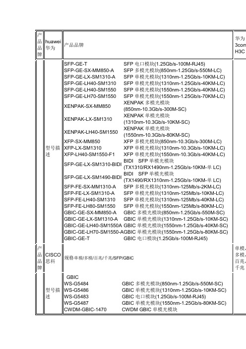
SFP-GE-S
DDM SFP多模光模块(850nm-1.25Gb/s-550M-LC)
SFP-GE-L
DDM SFP单模光模块(1310nm-1.25Gb/s-10KM-LC)
SFP-GE-Z
DDM SFP单模光模块(1550nm-1.25Gb/s-80KM-LC)
XENPAK
SFP-GE-LH40-SM1310
SFP单模光模块(1310nm-1.25Gb/s-40KM-LC)
SFP-GE-LH40-SM1550
SFP单模光模块(1550nm-1.25Gb/s-40KM-LC)
SFP-GE-LH70-SM1550
SFP单模光模块(1550nm-1.25Gb/s-70KM-LC)
BIDI SFP单模光模块(TX1310/RX1490nm-1.25Gb/s-10KM-单LC)
SFP-GE-LX-SM1490-BIDI
BIDI SFP单模光模块(TX1490/RX1310nm-1.25Gb/s-10KM-单LC)
SFP-FE-SX-MM1310-A
SFP多模光模块(1310nm-125Mb/s-2KM-LC)
SFP-OC3-LR2
OC3 SFP单模光模块(1550nm-155Mb/s-80KM-LC)
SFP-OC12-MM
OC12 SFP多模光模块(1310nm-622Mb/s-2KM-LC)
SFP-OC12-SR
OC12 SFP多模光模块(1310nm-622Mb/s-2KM-LC)
SFP-OC12-IR1
CWDM-SFP-1550
CWDM SFP单模光模块(1550nm-1.25Gb/s-80KM-LC)
接收(receiver)波长为1490nm范围:1480-1450nm

SFP是SMALL FORM PLUGGABLE的缩写SFF封装-----焊接小封装光模块1、目前我们自制光模块的区别:210040000143 TX-SD的输出部分串联一个0欧姆输出到CPU210040000122 TX-SD的输出部分串联一个10K欧姆输出到CPU,210040000143把10K改为0欧是因为加了10K后可能对EPON电路有影响;210040000095和210040000144的区别:TX-SD检测输出这块电路中的电压比较器电路有了改动,其中,210040000144把由原来95中用电阻来固定电压比较器的输入电压变为正端为2.8V,负端在激光二极管导通后在相邻二极管负端产生2.2V电压来产生电压比较器的输入电压;210040000095和210040000096区别是:210040000096上面有颗芯片比较贵,换成95方案,96光模块现在停用;2、(ONU)光模块波长:发送(Transmitter)波长为1310nm范围:1260-1360nm接收(Receiver)波长为1490nm范围:1480-1450nm线路码型:8B/10B3、光模块灵敏度:-27dBm关断发送光功率:-45dBm4、饱和光功率:-3 dBm 最大可接收功率叫做饱和光功率,也叫过载光功率。
指光模块接收端最大可以检测到的光功率。
当接收光功率大于过载光功率时,会导致误码发生;因此对于发光功率的模块不加衰减回环测试会出现误码现象,按照最坏值的设计思想,若收端功率不过载,须满足:发送端最大发送光功率减去光纤传输端实际衰减值后应小于过载光功率;否则需加衰减器,通常对于中长距离的光器件,才有可能存在光功率过载问题;5、通常工程上要求正常工作接收光功率小于过载光功率3-5dBm,大于接收灵敏度3-5dBm,一般来说不管是单模接口或者多模接口,实际接收光功率为-5 到 -15 dBm之间算是比较合理的工作范围;6、数据输入输出接口逻辑电平:LVPECL(Low V oltage Positive Emitter Coupled Logic低压正发射极耦合逻辑) 电平,其电平标准为:V CC=3.3V,V OH=2.42V, V OL=1.58V , V IH=2.06V,V IL=1.94VCML输入摆幅电压为:V ID=400mV,输出摆幅电压为:V OD=800mV;LVPECL输入摆幅电压为:V ID=310mV,输出摆幅电压为:V OD=800mV;LVPECL:输入高电平:VCC-1.17V---VCC-0.88V(2.13V---2.42V)输入低电平:VCC-1.81V---VCC-1.47V (1.49V---1.83V)输出高电平:VCC-1.02V---VCC-0.88V (2.28V---2.42V)输出低电平:VCC-1.81V---VCC-1.62V (1.49V---1.68V)9、10pin RD-,RD+ CML电平输出;Data Output Differential Swing 400mV—1000mV14、15pin TD-,TD+ LVPECL电平输入;Data Input Differential Swing 200mV--- 1600mVTTL: 输入高电平: 2V----VCC输入低电平: 0V----0.8V输出高电平: 2.4V---VCC输出低电平: 0V----0.4V8、PX20和PX20+的区别:描述PX20 ONU PX20+ ONU平均发射光功率(MAX) 4 dBm 4 dBm平均发射光功率(MIN) -1dBm 0dBm接收灵敏度(MAX)-24 dBm -27 dBm过载光功率 -3dBm -3dBm光模块类型下行最大插损上行最大插损下行最小插损上行最小插损PX20 26dB 26 dB 10 dB 10 dBPX20+ 29.5 dB 30 dB 10 dB 10 dB实际应用中留有3dB的余量;突发开关时间小于30ns10、2X10光模块和2X5的光模块的区别:2X10光模块和2X5的光模块相比,区别就是多了DDMI功能(digital diagnostic monitoring interface)DDMI功能是由协议要求的,SFF 8472协议主要就是规范大家的DDM上报的一些格式;我们常用的DDM上报量有5个:–工作电压–工作温度–激光器偏置电流–模块发射光功率–模块接收光功率•现在模块的DDM上报都是通过I2C和MAC芯片进行通信,MAC芯片和光模块进行通信,实际上就是夺取光模块内部的两个列表A0和A2,见下面图示。
10g bidi 10km成对的波长搭配关系

10G BIDI 10km成对的波长搭配关系
10G BIDI 10km 光模块的成对波长是指在同一个光模块中,发送端和接收端使用的波长是相同的两个波长。
这些波长是专门设计用于在单模光纤上进行双向传输,即发送和接收两个方向的信号可以同时传输。
这些波长的具体数值是根据标准规定的WDM (波分复用)技术进行设计的。
10G BIDI TX 1310nm 和10G BIDI RX 1490nm 是一对波长,其中发送端使用波长为1310nm,接收端使用波长为1490nm。
这对波长的传输距离为10km,可以在单模光纤上实现双向传输。
另一对波长是10G BIDI TX 1270nm 和10G BIDI RX 1550nm,其中发送端使用波长为1270nm,接收端使用波长为1550nm。
这对波长的传输距离也是10km,同样可以在单模光纤上实现双向传输。
需要注意的是,这两对波长的传输距离虽然都是10km,但它们所使用的光纤长度是有限制的。
如果使用的光纤长度超过了这个限制,就需要使用其他波长或其他传输技术来实现更远距离的传输。
此外,使用这些波长的BIDI 光模块时,还需要注意光纤的品质和长度,以确保传输的稳定性和可靠性。
